1
www.sauservice.com
1ST PRINTING NOVEMBER ‘04
®
Deluxe Version
Owner’s Manual
SEGA AMUSEMENTS USA, INC.
MANUAL NO. 4201-6831-01
GAME CODE: CTF
BEFORE USING THE PRODUCT, BE SURE TO READ THE FOLLOWING:
To maintain the safety:
To ensure the safe usage of the product, be sure to read the following before using the product. The
following instructions are intended for the users, operators and the personnel in charge of the operation of the product. After carefully reading and sufficiently understanding the warning displays and
cautions, handle the product appropriately. Be sure to keep this manual nearby the product or elsewhere convenient for referring to it when necessary.
Herein, explanations which require special attention are enclosed with dual lines. Depending on the
potentially hazardous degrees, the terms of WARNING, CAUTION, etc. are used. Be sure to understand the contents of the displays before reading the text.
WARNING!
Indicates that mishandling the product by disregarding this warning
will cause a potentially hazardous
situation which can result in death
or serious injury.
CAUTION!
Indicates that mishandling the product
by disregarding this caution will cause
a slight hazardous situation which can
result in personal injury and or material
damage.
For the safe usage of the product, the following pictographs are used:
Indicates “HANDLE WITH CARE.” In order to protect the human body an equipment,
this display is attached to places where the Owner’s Manual and or Service Manual should
be referred to.
Perform work in accordance with the instructions herein stated.
Instructions for work are explained by paying attention to the aspect of accident prevention. Failing to
perform work as per the instructions can cause accidents. In the case where only those who have technical expertise should perform the work to avoid hazardous situation, the instructions herein state that the
serviceman should perform such work.
Be sure to turn off power before working on the machine.
To prevent electric shock, be sure to turn off power before starting the work in which the worker touches
the interior of the product. If the work is to be performed in the power-on status, the Instruction Manual
herein always states to that effect.
Be sure to ground the Earth Terminal (this, however, is not required in the case where a power cord
with earth is used).
This product is equipped with the Earth Terminal. When installing the product, Connect the Earth Terminal to the “accurately grounded indoor earth terminal” by using an earth wire. Unless the product is
grounded appropriately, the user can be subject to electric shock. After performing repair, etc. for the
Control equipment, ensure that the Earth Wire is firmly connected to the Control equipment.
Ensure that the Power Supply used is equipped with an Earth Leakage Breaker.
This product does not incorporate the Earth Leakage Breaker. Using a power supply which is not
equipped with the Earth Leakage Breaker can cause a fire when earth leakage occurs.
Be sure to use fuses which meet the specified rating. (only for the machines which use fuses).
Using fuses exceeding the specified rating can cause a fire and electric shock.
Specification changes (removal of equipment, conversion and addition) not designated by SEGA
are not allowed.
The parts of the product include warning labels for safety, covers for personal protection, etc. It is
very hazardous to operate the product by removing parts and or modifying the circuits. Should doors,
lids and protective parts be damaged or lost, refrain from operating the product, and contact where the
product was purchased from or the office herein stated. SEGA shall not be held responsible for any
accidents, compensation for damage to a third party, resulting from the specifications not designated by
SEGA.
Ensure that the product meets the requirements of appropriate Electrical Specifications.
Before installing the product, check for Electrical Specifications. SEGA products have a nameplate on
which Electrical Specifications are described. Ensure that the product is compatible with the power
supply voltage and frequency requirements of the location. Using any Electrical Specifications different
from the designated Specifications can cause a fire and electric shock.
Install and operate the product in places where appropriate lighting is available, allowing warning
labels to be clearly read.
To ensure safety for the customers, labels and printed instructions describing potentially hazardous situation are applied to places where accidents can be caused. Ensure that where the product is operated
has sufficient lighting allowing the warnings to be read. If any label is peeled off, apply it again immediately. Please place an order with where the product was purchased from or the office herein stated.
When handling the Monitor, be very careful. (Applies only to the product w/monitor.)
Some of the monitor (TV) parts are subject to high tension voltage. Even after running off power, some
portions are still subject to high tension voltage sometimes. Monitor repair and replacement should be
performed only be those technical personnel who have knowledge of electricity and technical expertise.
Be sure to adjust the monitor (projector) properly. (Applies only to the product w/monitor.)
Do not operate the product leaving on-screen flickering or blurring as it is. Using the product with the
monitor not properly adjusted may cause dizziness or a headache to an operator, a player, or the customers.
When transporting or reselling this product, be sure to attach this manual to the product.
In the case where commercially available monitors and printers are used in this product, only the contents relating to this product are explained herein. Some commercially available equipment has functions and reactions not stated in this manual. Read this manual together with the specific Instruction
Manual of such equipment.
• Descriptions herein contained may be subject to improvement changes without notice.
• The contents described herein are fully prepared with due care. However, should any question arise or
errors be found, please contact SEGA.
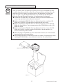
INSPECTIONS IMMEDIATELY AFTER TRANSPORTING THE PRODUCT TO THE LOCATION.
Normally, at the time of shipment, SEGA products are in a status allowing for usage immediately after
transporting to the location. Nevertheless, an irregular situation may occur during transportation. Before
turning on power, check the following points to ensure that the product has been transported in a satisfactory status.
Are there any dented portions or defects (cuts, etc.) on the external surfaces of the cabinet?
Are Casters and Adjusters, damaged?
Do the power supply voltage and frequency requirements meet with those of the location?
Are all wiring connectors correctly and securely connected? Unless connected in the correct direction,
connector connections can not be made accurately. Do not insert connectors forcibly.
Do power cords have cuts and dents?
Do the fuses used meet specified rating? Is the Circuit Protector in an energized status?
Are all accessories available?
Can all Doors and Lids be opened with the Accessory keys? Can Doors and Lids be firmly closed?
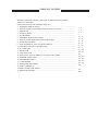
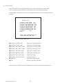
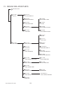
TABLE OF CONTENTS
BEFORE USING THE PRODUCT, BE SURE TO READ THE FOLLOWING:
TABLE OF CONTENTS
INTRODUCTION OF THE OWNER’S MANUAL
1. HANDLING PRECAUTIONS ..........................................................................................
2. PRECAUTIONS CONCERNING INSTALLATION LOCATION ...................................
3. OPERATION .....................................................................................................................
4. NAME OF PARTS ............................................................................................................
5. ACCESSORIES .................................................................................................................
6. ASSEMBLY AND INSTALLATION ................................................................................
7. PRECAUTIONS WHEN MOVING THE MACHINE .....................................................
8. GAME DESCRIPTION .....................................................................................................
9. EXPLANATION OF TEST AND DATA DISPLAY .........................................................
10. CONTROL UNIT (GUN CONTROLLER) .......................................................................
11. 1C CARD UNIT .................................................................................................................
12. PROJECTOR ......................................................................................................................
13. COIN SELECTOR .............................................................................................................
14. REPLACING THE FLUORESCENT LIGHTS AND LAMPS .......................................
15. PERIODIC INSPECTION .................................................................................................
16. TROUBLESHOOTING .....................................................................................................
17. GAME BOARD .................................................................................................................
18. DESIGN RELATED PARTS ...............................................................................................
19. PARTS **MISSING** ........................................................................................................
20. WIRE COLOR CODE TABLE ...........................................................................................
21. WIRING DIAGRAMS ........................................................................................................
1 - 2
3 - 4
5 - 8
9
10 - 15
16 - 42
43 - 45
46 - 62
63 - 88
89 - 95
96 - 102
103- 112
113
114- 117
118- 119
120- 128
129- 138
139
140
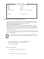
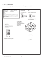
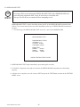
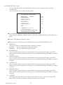
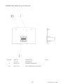
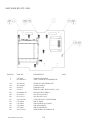
XXX
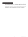
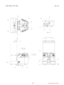
Installation Space
Height
Width
Length
Weight
Power, maximum current
MONITOR
SPECIFICATIONS
:
:
:
:
:
:
47.2 inches width X 66.1 inches
87.8 inches
47.2 inches
58.1 inches
557.8 lbs
590 W 6.31 A (AC 120V 60 Hz AREA)
: 50 Type Projection Display
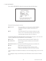
INTRODUCTION OF THE OWNERS MANUAL
This Owner's Manual is intended to provide detailed descriptions together with all the
necessary information covering the general operation of electronic assemblies, electromechanicals, servicing control, spare parts, etc. as regards the product,
SEGA GHOST SQUAD DELUXE TYPE.
This manual is intended for the owners, personnel and managers in charge of operation
of the product. Operate the product after carefully reading and sufficiently understanding the instructions. If the product fails to function satisfactorily, non-technical personnel
should under no circumstances touch the internal system. Please contact where the product was purchased from.
Use of this product is unlikely to cause physical injuries or damages to property. However,
where special attention is required this is indicated by a thick line, the word "IMPORTANT"
and its sign in this manual.
STOP
Indicates that mishandling the product by disregarding this display can cause the
product's intrinsic performance not to be obtained, resulting in malfunctioning.
IMPORTANT!
SEGA AMUSEMENTS USA, INC. / CUSTOMER SERVICE
45133 Industrial Drive, Fremont, California 94538, U.S.A.
Phone : (415) 701-6580
Fax : (415) 701-6594
◆ PRODUCTION DATE ◆
This SEGA product was produced in the year of:
2004
This signifies that this work was disclosed in 2004.
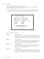
DEFINITION OF LOCATION MAINTENANCE MAN AND SERVICEMAN
WARNING!
Non-technical personnel who do not have technical knowledge and expertise should
refrain from performing such work that this manual requires the location's maintenance man or a serviceman to carry out, or work which is not explained in this
manual. Failing to comply with this instruction can cause a severe accident such
as electric shock.
Ensure that parts replacement, servicing & inspections, and troubleshooting are performed by the
location's maintenance man or the serviceman. It is instructed herein that particularly hazardous work
should be performed by the serviceman who has technical expertise and knowledge.
The location's maintenance man and serviceman are herein defined as follows:
"Location's Maintenance Man" :
Those who have experience in the maintenance of amusement equipment and vending machines, etc.,
and also participate in the servicing and control of the equipment through such routine work as equipment assembly and installation, servicing and inspections, replacement of units and consumables, etc.
within the Amusement Facilities and or locations under the management of the Owner and Owner's
Operators of the product.
Activities of Location's Maintenance Man :
Assembly & installation, servicing & inspections, and replacement of units & consumables as regards
amusement equipment, vending machines, etc.
Serviceman :
Those who participate in the designing, manufacturing, inspections and maintenance service of the
equipment at an amusement equipment manufacturer.
Those who have technical expertise equivalent to that of technical high school graduates as regards
electricity, electronics and or mechanical engineering, and daily take part in the servicing & control
and repair of amusement equipment.
Serviceman's Activities :
Assembly & installation and repair & adjustments of electrical, electronic and mechanical parts of
amusement equipment and vending machines.
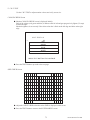
������
��
����
�
�����������������
Notes:
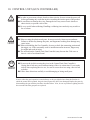
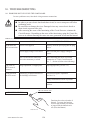
1. HANDLING PRECAUTIONS
When installing or inspecting the machine, be very careful of the following points and pay attention to
ensure that the player can enjoy the game safely.
Non-compliance with the following points or inappropriate handling running counter to the cautionary
matters herein stated can cause personal injury or damage to the machine.
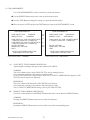
WARNING!
● Before performing work, be sure to turn power off. Performing the work without
turning power off can cause an electric shock or short circuit. In the case work
should be performed in the status of power on, this manual always states to that effect.
● To avoid electric shock or short circuit, do not plug in or unplug quickly.
● To avoid electric shock, do not plug in or unplug with a wet hand.
● Do not expose Power Cords and Earth Wires on the surface, (floor, passage, etc.).
If exposed, the Power Cords and Earth Wires are susceptible to damage. Damaged
cords and wires can cause electric shock or short circuit.
● To avoid causing a fire or electric shock, do not put things on or damage Power
Cords.
● When or after installing the product, do not unnecessarily pull the power cord. If
damaged, the power cord can cause a fire or electric shock.
● In case the power cord is damaged, ask for replacement through where the product
was purchased from or the office herein stated. Using the cord as is damaged can
cause fire, electric shock or leakage.
● Be sure to perform grounding appropriately. Inappropriate grounding can cause an
electric shock.
● Be sure to use fuses meeting specified rating. Using fuses exceeding the specified
rating can cause a fire or electric shock.
● Completely make connector connections for IC BD and others. Insufficient insertion
can cause an electric shock.
● Specification changes, removal of equipment, conversion and/or addition, not designated by SEGA are not permitted.
• Failure to observe this may cause a fire or an electric shock. Non-compliance with
this instruction can have a bad influence upon physical conditions of the players or
the lookers-on, or result in injury during play.
• SEGA shall not be held responsible for damage, compensation for damage to a third
party, caused by specification changes not designated by SEGA.
● Be sure to perform periodic maintenance inspections herein stated.
A
www.sauservice.com
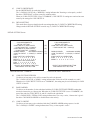
STOP
IMPORTANT!
● For the IC board circuit inspections, only the logic tester is allowed. The use of a
multiple-purpose tester is not permitted, so be careful in this regard.
● The Projector is employed for this machine. The Projector's screen is susceptible
to damage, therefore, be very careful when cleaning the screen. For details, refer to
PROJECTOR.
● Some parts are the ones designed and manufactured not specifically for this game
machine. The manufacturers may discontinue, or change the specifications of, such
general-purpose parts. If this is the case, Sega cannot repair or replace a failed game
machine whether or not a warranty period has expired.
www.sauservice.com
A
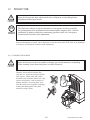
2. PRECAUTIONS CONCERNING INSTALLATION LOCATION
WARNING!
This product is an indoor game machine. Do not install it outside. Even indoors, avoid
installing in places mentioned below so as not to cause a fire, electric shock, injury and
or malfunctioning.
● Places subject to rain or water leakage, or places subject to high humidity in the
proximity of an indoor swimming pool and or shower, etc.
● Places subject to direct sunlight, or places subject to high temperatures in the proximity of heating units, etc.
● Places filled with inflammable gas or vicinity of highly inflammable/volatile chemicals or hazardous matter.
● Dusty places.
● Sloped surfaces.
● Places subject to any type of violent impact.
● Vicinity of anti-disaster facilities such as fire exits and fire extinguishers.
● The operating (ambient) temperature range is from 5˚ to 30˚.
LIMITATIONS OF USAGE REQUIREMENTS
WARNING!
● Be sure to check the Electrical Specifications.
Ensure that this product is compatible with the location's power supply, voltage and
frequency requirements.
A plate describing Electrical Specifications is attached to the product.
Non-compliance with the Electrical Specifications can cause a fire and electric
shock.
● This product requires the Breaker and Earth Mechanisms as part of the location
facilities. Using them in a manner not independent can cause a fire and electric
shock.
● Ensure that the indoor wiring for the power supply is rated at 15 A or higher (AC
single phase 100~120 V area). Non-compliance with the Electrical Specifications
can cause a fire and electric shock.
● Be sure to independently use the power supply equipped with the Earth Leakage
Breaker. Using a power supply without the Earth Leakage Breaker can cause an
outbreak of fire when earth leakage occurs.
● Putting many loads on one electrical outlet can cause generation of heat and a fire
resulting from overload.
● When using an extension cord, ensure that the cord is rated at 15 A or higher (AC
100~120 V area). Using a cord rated lower than the specified rating can cause a fire
and electric shock.
3
www.sauservice.com
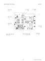
OPERATION AREA
WARNING!
STOP
IMPORTANT!
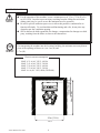
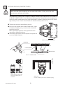
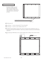
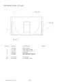
● For the operation of this machine, secure a minimum area of 2.3 m (7.5 ft) (W)×2.8
m (9.2 ft) (D). In order to prevent injury resulting from the falling down accident
during game play, be sure to secure the minimum area for operation.
● Be sure to provide sufficient space so as to allow this product's ventilation fan to
function efficiently. To avoid machine malfunctioning and a fire, do not place any
obstacles near the ventilation opening.
● SEGA shall not be held responsible for damage, compensation for damage to a third
party, resulting from the failure to observe this instruction.
For transporting the machine into the location's building, the minimum necessary dimensions of the opening (of doors, etc.) are 1 m (W) and
1.7 m (H).
Electric current consumption
150mm (5.9in)
2.8m (9.2ft)
MAX. 6.31 A (AC 120 V, 60 Hz)
MAX. 3.41 A (AC 220 V, 50 Hz)
MAX. 3.28 A (AC 220 V, 60 Hz)
MAX. 3.22 A (AC 240 V, 50 Hz)
MAX. 6.6 A (AC 110V, 60Hz; TAIWAN)
2.3m (7.5ft)
FIG. 2
www.sauservice.com
4
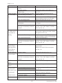
3. OPERATION
PRECAUTIONS TO BE HEEDED BEFORE STARTING THE OPERATION
To avoid injury and trouble, be sure to constantly give careful attention to the behavior and manner of the visitors and players.
In order to avoid accidents, check the following before starting the operation:
● To ensure maximum safety for the players and the customers, ensure that where the
product is operated has sufficient lighting to allow any warnings to be read. Operation under insufficient lighting can cause bodily contact with each other, hitting accident, and or trouble between customers.
● Be sure to perform appropriate adjustment of the monitor (projector). For operation of this machine, do not leave monitor's flickering or deviation as is. Failure to
observe this can have a bad influence upon the players' or the customers' physical
conditions.
● It is suggested to ensure a space allowing the players who feel sick while playing the
game to take a rest.
● Check if all of the adjusters are in contact with the surface. If they are not, the Cabinet can move and cause an accident.
Approx. 5mm
WARNING!
Ensure that all of the Adjusters are in contact with the floor.
FIG. 3
5
www.sauservice.com
WARNING!
CAUTION!
STOP
IMPORTANT!
● Do not put any heavy item on this product. Placing any heavy item on the product
can cause a falling down accident or parts damage.
● Do not climb on the product. Climbing on the product can cause falling down
accidents. To check the top portion of the product, use a step.
● To avoid electric shock, check to see if door & cover parts are damaged or omitted.
● To avoid electric shock, short circuit and or parts damage, do not put the following
items on or in the periphery of the product.
Flower vases, flowerpots, cups, water tanks, cosmetics, and receptacles/containers/
vessels containing chemicals and water.
● To avoid injury, be sure to provide sufficient space by considering the potentially
crowded situation at the installation location. Insufficient installation space can
cause making bodily contact with each other, hitting accidents, and or trouble
between customers.
● During daily cleaning and maintenance, check the surface of the control unit
(Gun Controller) for cracks and other damage and ensure that screws are securely
fastened. Loose screws, cracks, and other damage could cause harm to players and
other customers if left unrepaired.
Players with bare hands directly hold the controller. For operation, it is recommended
that the wet towels (paper towels) be provided.
www.sauservice.com
6
PRECAUTIONS TO BE HEEDED DURING OPERATION(PAYING ATTENTION TO CUSTOMERS)
To avoid injury and trouble, be sure to constantly give careful attention to the behavior and manner of the visitors and players.
WARNING!
● To avoid injury and accidents, those who fall under the following categories are not
allowed to play the game.
• Those who need assistance such as the use of an apparatus when walking.
• Those who have high blood pressure or a heart problem.
• Those who have experienced muscle convulsion or loss of consciousness when playing
video game, etc.
• Those who have a trouble in the neck and or spinal cord.
• Intoxicated persons.
• Pregnant women or those who are in the likelihood of pregnancy.
• Persons susceptible to motion sickness.
• Persons whose act runs counter to the product's warning displays.
● A player who has never been adversely affected by light stimulus might experience
dizziness or headache depending on his physical condition when playing the game.
Especially, small children can be subject to those conditions. Caution guardians of
small children to keep watch on their children during play.
● Instruct those who feel sick during play to have a medical examination.
● To avoid injury resulting from falling down and electric shock due to spilled drinks,
instruct the player not to place heavy items or drinks on the product.
● To avoid electric shock and short circuit, do not allow customers to put hands and
fingers or extraneous matter in the openings of the product or small openings in or
around the doors.
● To avoid falling down and injury resulting from falling down, immediately stop the
customer's leaning against or climbing on the product, etc.
● To avoid electric shock and short circuit, do not allow the customers to unplug the
power plug without a justifiable reason.
CAUTION!
● Immediately stop such violent acts as hitting and kicking the product. Such violent
acts can cause parts damage or falling down, resulting in injury due to fragments and
falling down.
● Playing close to the cabinet could cause the Gun Controller to strike the cabinet,
possibly causing an accident. Be sure to ask your customers to maintain a safe
distance during play.
● Wearing large rings and other accessories during play could result in injury to
players' fingers. Be sure to ask your customers to remove such accessories before
playing.
7
www.sauservice.com
STOP
IMPORTANT!
● The Gun Controller for use on 1P side (left side) and 2P side (right side) are
different. Ensure that players do not confuse the right and left side guns when
starting play.
● Make sure to avoid disturbing customers when moving/removing the machine from
its current location.
www.sauservice.com
8
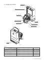
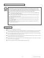
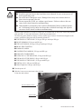
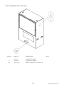
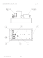
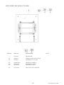
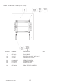
4. NAME OF PARTS
BILLBOARD
PTV
.
50 TYPE PROJECTION DISPLAY
IC CARD UNIT
COIN CHUTE DOOR
PTV BASE
CASHBOX DOOR
GUN CONTROLLER
MAIN CABLINET
AC UNIT
FIG. 4
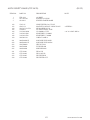
TABLE 4
PTV
PTV BASE
BILLBOARD
MAIN CABINET
When assembled
Width
88.19 in
47.2 in
46.06 in
44.9 in
47.24 in
×
Depth ×
× 21.9 in ×
× 24.4 in ×
× 16.14 in ×
× 42.91 in ×
× 66.14 in ×
9
Height
65.7 in
12.2 in
15.16 in
39.76 in
67.8 in
Weight
220.4 lb
57.3 lb
39.68 lb
216.05 lb
557.77 lb
www.sauservice.com
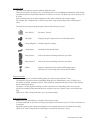
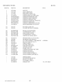
5. ACCESSORIES
When transporting the machine, make sure that the following parts are supplied.
TABLE 5 a ACCESSORIES
DESCRIPTION
Part No.(Qty.)
Note
KEY MASTER
220-5576 (2)
For opening/closing
the doors
OWNERS MANUAL
4201-6831-01
Figures
KEY
(2)
For the CASHBOX DOOR
NOTE: Parts not labeled with part numbers are as yet
unregistered or cannot be registered. Be sure to handle
all parts with care, as some parts are not available for
purchase separately.
The Keys are inside the Coin
Chute Door at the time of shipment from the factory.
TOSHIBA
200-5536 (1)
Remote Controller used for
adjustment of the projector.
See Section 12.
TEST
MODE
WRITING
R
G
B
POSITION
ADJUST
CARTON BOX
601-11219-01 (1)
Used for transporting the
Game Board.
See FIG. 5 a.
P
SET
PIC-ADJ
RESET
L-WRENCH
540-0043-91 (1)
SELECT
The Remote Controller is attached to
the Projector at the time of shipment.
www.sauservice.com
10
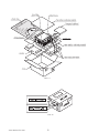
HOW TO USE THE CHIHIRO BOARD CARTON BOX
STOP
IMPORTANT!
Replacement or repair of the Game Board (Chihiro) for this product should be undertaken at the appropriate repair center. Be sure to follow the specifications below when
requesting repairs/sending the board to the repair center. Not following the specifications
may result in the board not being accepted or in extra charges being made.
● Put the game board in the carton box as is. Do not carry out any disassembly or part
removal other than that specified.
● Follow the procedure and instructions regarding direction below when placing the
Game Board in the carton box.
● When packing the game board with the Media Board attached, do not remove the
Key Chip.
● When packing the game board with the Media Board detached, be sure to include
the AVIP Cable.
● When packing, attach the accessory stickers in the specified places on the Game
Board and carton box.
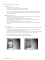
INSTRUCTIONS
● Wrap the Chihiro Board in a plastic bag.
● Place it on top of the bottom surface cushioning material. Turn the Filter Board to face the side with the
three honeycomb buffers. Placing it in the opposite direction may cause damage to the Filter Board.
● Insert corrugated cardboard into the space between the lateral honeycomb buffers of the bottom surface
cushioning material and stow the AVIP cable inside.
● Place the Chihiro Board wrapped in the bottom surface cushioning material into the carton box. Use the
handles on the bottom surface cushioning material.
● Place the upper surface cushioning material on top of the Chihiro Board. Be sure to align it in the right
direction, as it will not fit otherwise.
● Close the top of the carton box and seal it tightly with adhesive tape.
11
www.sauservice.com
FIG. 5 a
FIG. 5 b
www.sauservice.com
12
The following Table 5b lists the parts that had been separately packed when the product was shipped
from the factory but are necessary when you use the product. These parts will be mounted on the product
when installing and assembling it.
TABLE 5 b
GD SOFT KIT CTF
KEY CHIP (1)
See 6 of Section 6.
CUSHION SPONGE
601-11137 (1)
GD-ROM Disc Protector
GD SOFT CTF
See 6 of Section 6.
NOTE: When you order the GD-ROM disc only, specify the part
number 610-0652-0012 (GD SOFT CTF).
13
www.sauservice.com
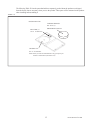
The following Table 5c lists the parts that are separately marketed but are necessary when
booting this product's software. When having unpacked the shipping crate, make sure that all the
parts in this Table 5c are in the crate. If not so, contact where you have obtained the product.
TABLE 5 c (XKT-0833 : GD-ROM DRIVE KIT)
GD-ROM DRIVE CARTON BOX
(1)
Used for transporting the GD-ROM DRIVE.
See FIG. 5 d.
123
GD-ROM DRIVE
610-0617
(1)
610-0617-01
Device that loads the software in a GD-ROM disc.
See 6 of Section 6.
This carton box is a standard accessory of
the GD-ROM drive. If you want to obtain the
carton box itself separately, specify the part
number 601-11031.
www.sauservice.com
14
HOW TO USE THE CARTON BOX (GD-ROM DRIVE)
STOP
IMPORTANT!
When you want to order for replacing or repairing service of the GD-ROM drive that
is used by the product, pack it in a carton box as instructed below, and then deliver the
carton box to a service agent. If you do not observe the instruction, your order may
not be accepted or may be charged additionally. If you handle the GD-ROM drive
differently from the following instructions, its components may be damaged.
● Contain the GD-ROM drive in a dedicated carton box. Do not disassemble it or
remove any part from it unless otherwise instructed.
● Before containing the GD-ROM drive in a dedicated carton box, attach the GDROM drive lid (DISC LID) onto the drive and fix the lid with a screw.
● Before containing the GD-ROM drive in a dedicated carton box, remove the GDROM disc from the drive. Do not attempt to move the GD-ROM drive with a GDROM disc inside.
● Before containing the GD-ROM drive in a dedicated carton box, remove the GDROM drive bracket. Carefully keep the GD-ROM drive bracket and the 4 set
screws, because they will be reused.
● When inserting the GD-ROM drive into a dedicated carton box, be careful about an
inserting direction as illustrated below.
● The packing materials in a carton box are used as a cushion. Use them always when
inserting the GD-ROM drive into a dedicated carton box. Do not bend them.
Remove the GD drive bracket.
FIG. 5 c
15
www.sauservice.com
6. ASSEMBLY AND INSTALLATION
WARNING!
CAUTION!
● Perform assembly work by following the procedure herein stated. Failing to comply
with the instructions can cause electric shock hazard.
● Perform assembling as per this manual. Since this is a complex machine, erroneous
assembling can cause an electric shock, machine damage and or not functioning as
per specified performance.
● When assembling, be sure to use plural persons. Depending on the assembly work,
there are some cases in which working by one person alone can cause personal
injury or parts damage.
● Ensure that connectors are accurately connected. Incomplete connections can cause
electric shock hazard.
● Be careful not to damage the wires. Damaged wires may cause electric shock or
short circuit or present a fire risk.
● Do not carelessly push the PTV. Pushing the PTV carelessly can cause the PTV to
fall down.
● This work should be performed by the site maintenance individual or other skilled
professional. Performing work by non-technical personnel can cause a severe
accident such as electric shock. Failing to comply with this instruction can cause a
severe accident such as electric shock to the player during operation.
● Provide sufficient space so that assembling can be performed. Performing work in
places with narrow space or low ceiling may cause an accident and assembly work
to be difficult.
● To perform work safely and avoid serious accident such as the cabinet's falling
down, do not perform work in places where step-like grade differences, a ditch, or
slope exist.
● Do not use this product with connectors other than those that were connected and
used with the Game Board at the time of shipping. Do not carelessly connect wires
to connectors that were not used at the time of shipping, as this may cause overheating, smoke or fire damage.
● When handling plastic parts, use care. Do not give a shock or apply excessive load
to the fluorescent lamps and plastic parts. Failure to observe this can cause parts
damage, resulting in injury due to fragments, cracks and broken pieces.
● To perform work safely and securely, be sure to prepare a step which is in a secure
and stable condition. Performing work without using the step can cause violent
falling down accidents.
● Make sure that the GD cable connector is inserted parallel to the plug. Improper
insertion may cause damage to the connector and present a fire risk.
www.sauservice.com
16
When carrying out the assembling and installation, follow the following 9-item sequence.
1
ASSEMBLING THE BILLBOARD
2
ASSEMBLING THE PTV
3
ASSEMBLING THE CABINET
4
SECURING IN PLACE(ADJUSTER TUNING)
5
ATTACHING THE FLUORESCENT LIGHTS AND LAMPS
6
INSTALLING THE GD-ROM DRIVE(SETTING THE GD-ROM DISC)
7
POWER SUPPLY AND EARTH CONNECTION
8
TURNING THE POWER ON
9
ASSEMBLY CHECK
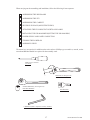
The master key (accessories) in addition to the tools such as a Phillips type screwdriver, wrench, socket
wrench and Ratchet Handle are required for the assembly work.
Phillips type screwdriver
(for screw)
WRENCH (for hexagon bolt)
SOCKET WRENCH, (for hexagon bolt)
RATCHET HANDLE
KEY MASTER
L-WRENCH (3mm L-shaped hex wrench, included)
17
www.sauservice.com
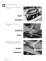
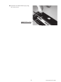
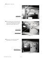
1
ASSEMBLING THE BILLBOARD
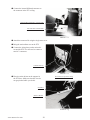
● Undo the 2 truss screws, and remove the
pop bracket.
POP BRACKET
TRUSS SCREW (2), black
M4×8
PHOTO 6. 1 a
● Undo the 3 truss screws, and remove the
pop holder.
TRUSS SCREW (3), black
M4×8
POP HOLDER
PHOTO 6. 1 b
● Attach the billboard pop by fitting it between the pop bracket and pop holder, and
fixing it in place with the 3 truss screws.
BILLBOARD POP
TRUSS SCREW (3), black
M4×8
PHOTO 6. 1 c
www.sauservice.com
18
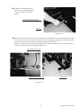
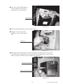
● Attach the assembled billboard pop using
the 2 truss screws.
TRUSS SCREW (2), black
M4×8
PHOTO 6. 1 d
19
www.sauservice.com
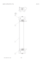
2
ASSEMBLING THE PTV
● By using 2 Flat Head screws, secure the 2 Mask Bracket Uppers to the PTV ceiling.
● Secure the Mask Bracket Lower to the front of PTV with 4 screws.
FLAT HEAD SCREW (2 each)
M4×8
MASK BRACKET UPPER
MASK BRACKET LOWER
SCREW (4), black
M5×16, w/flat & spring washers
FIG. 6. 2 a
www.sauservice.com
20
● Install Mask to the PTV front. Install the Mask in a manner hooking up to both 2 Mask
Bracket Uppers and the Mask Bracket Lower. Simultaneously insert the projections of
the Mask into the square holes in the PTV screen left and right.
● Secure the Mask by fastening a screw for each from both sides of PTV.
TRUSS SCREW (2), black
M5×25, flat washer used
MASK
FIG. 6. 2 b
● Affix the side bracket L and side bracket R to the PTV front face using 2 screws each. Be careful of the
orientation of the parts.
SIDE BRACKET L
SIDE BRACKET R
SCREW (2 ea), black
M5×16, w/flat & spring washers
PHOTO 6. 2 a
21
www.sauservice.com
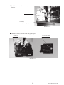
3
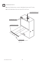
ASSEMBLING THE CABINET
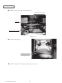
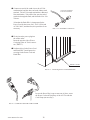
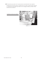
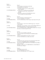
● Move the PTV to the back of the PTV base.
● Put the PTV on the PTV base. To do this, you will need at least 4 people to lift the PTV, and another person to hold the PTV base to stop it from moving. Lower the PTV until it touches the supports. Take care
not to damage any wiring during this step.
PTV
SUPPORT
PTV BASE
FIG. 6. 3 a
You will need at least 5 people to
perform this step.
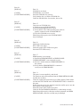
● Attach the front panel using 4 truss screws. Take care
that you do not damage any wiring during this step.
FRONT PANEL
TRUSS SCREW (4), black
M5×20, flat washer used
PHOTO 6. 3 a
www.sauservice.com
22
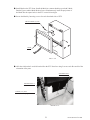
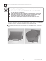
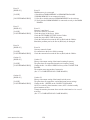
● Have 2 people lift the billboard and place it on the PTV. Lower the
billboard so that the two mask bracket uppers that were attached in step
2 fit into the 2 rectangular holes in the billboard base plate, and push the
billboard towards the PTV screen. The base plate of the billboard is then
fixed into place by fitting into the mask brackets.
You will need 2 people to perform this step.
PHOTO 6. 3 b
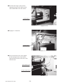
● You will need a footstool to complete the
following step. Attach the billboard to the
PTV using 2 screws.
BILLBOARD
SCREW (2)
t
M5×16, w/flat & spring washers
You will need a footstool to
perform this step.
PHOTO 6. 3 c
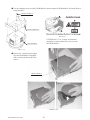
● Undo the single truss screw and remove the connector lid.
CONNECTOR LID
TRUSS SCREW (1), black
M4×8
PHOTO 6. 3 d
23
www.sauservice.com
● Connect the internal billboard connector to
the connector in the PTV ceiling.
BILLBOARD INTERNAL CONNECTOR
PTV CEILING CONNECTOR
PHOTO 6. 3 e
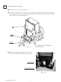
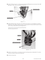
● Attach the connector lid using the single truss screw.
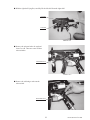
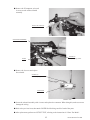
● Bring the main cabinet next to the PTV.
● Connect the wiring between the main cabi-
net and the PTV. You will need to connect a
total of 5 connectors.
CONNECTOR (5)
PHOTO 6. 3 f
● Place the main cabinet on the supports in
Be careful not to pinch the wiring.
the PTV base. Make sure that the wires do
not get pinched while you do this.
SUPPORT
MAIN CABINET
PHOTO 6. 3 g
www.sauservice.com
24
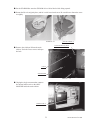
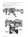
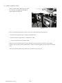
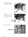
● Tighten the 2 hexagon bolts on
each of the left and right brackets
of the main cabinet to affix the
cabinet.
HEXAGON BOLT (2 ea), black
w/spring washer, flat washer used
t
BRACKET
PHOTO 6. 3 h
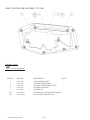
● Attach the joint bracket uppers to the left and right sides of the joint between the main cabinet and the
PTV using 4 truss screws on each side to secure the joint. Arrange these so that the vertical holes correspond to the main cabinet and the horizontal holes correspond to the PTV.
If there is a gap between the main cabinet and the PTV, adjust the main cabinet or the adjuster on the
PTV base to close the gap before tightening the screws.
JOINT BRACKET UPPER
TRUSS SCREW (4 ea), black
M5×20, flat washer used
ADJUSTER
PHOTO 6. 3 i
25
www.sauservice.com
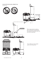
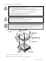
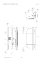
4
WARNING!
SECURING IN PLACE (ADJUSTER TUNING)
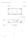
Make sure that all of the adjusters are in contact with the floor. If they are not, the cabinet can move and cause an accident.
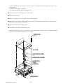
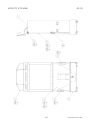
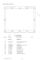
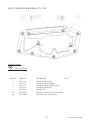
This product has 8 casters (4 for PTV Base, 4 for MAIN CABINET) and 6 Adjusters (4 for PTV Base, 2
for MAIN CABINET). (FIG. 6. 4 a) When the installation position is determined, cause the adjusters to
come into contact with the floor directly, make adjustments in a manner so that the casters will be raised
approximately 5 mm. from the floor and make sure that the machine position is level.
CASTER
● Transport the product to the installation position.
● Have all of the adjusters make contact with the floor. Adjust
the adjuster's height by using a wrench so that the machine
position is kept level.
When contacting the adjusters of the right and left fences
onto the floor, manually turn them.
● After making adjustment, fasten the adjuster nut upward and
secure the height of adjuster.
ADJUSTER
FIG. 6. 4 a BOTTOM VIEW
ADJUSTER
CASTER
Fasten Upward.
Approx.5mm
ADJUSTER
150mm
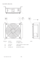
FIG. 6. 4 b ADJUSTER
FIG. 6. 4 c
Refer to this Fig. (Scale:1/100)
for the layout of the place of
installation.
www.sauservice.com
FIG. 6. 4 d
Provide ventilation space for the ventilation opening.
26
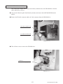
5
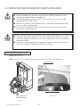
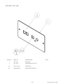
ATTACHING THE FLUORESCENT LIGHTS AND LAMPS
Fluorescent Light
● Undo the 4 screws using the supplied L-
wrench, and remove the instruction panel.
INSTRUCTION PANEL
HEXAGON SOCKET SCREW (4)
M5×10, special washer used
PHOTO 6. 5 a
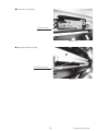
● Attach the globe-shaped fluorescent light.
GLOBE-SHAPED FLUORESCENT LIGHT 13W
390-6782
PHOTO 6. 5 b
● Reattach the instruction panel in its original position using the 4 screws.
27
www.sauservice.com
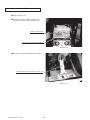
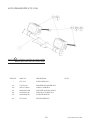
Halogen Lamp
● Undo the 4 truss screws, and remove the lamp lid.
TRUSS SCREW (2), black
M4×20
LAMP LID
TRUSS SCREW (2), black
M4×8
PHOTO 6. 5 c
● Attach the halogen lamp.
HALOGEN LAMP 40W
390-6732-40N
PHOTO 6. 5 d
● Reattach the lamp lid in its original position using the 4 screws.
www.sauservice.com
28
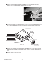
6
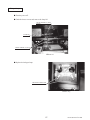
INSTALLING THE GD-ROM DRIVE (SETTING THE GD-ROM DISC)
STOP
IMPORTANT!
● Carefully handle the GD-ROM drive so as not to contaminate the disc and the readout lens with stains and dust particles.
● Do not continue to use the scratched GD-ROM disc. The scratched GD-ROM disc
may cause the system to malfunction.
● Set the GD-ROM disc onto the GD-ROM drive with its labeled side facing upward.
● The key chip is a precision device. Handle it carefully and avoid exposure to heat,
shock and static electricity, as these may cause damage to the device.
● The key chip is contained in the GD-ROM disc case. Always use them as a set.
This section explains how to remove the ASSY MAIN BD from the main cabinet, set the GD-ROM disc
onto the GD-ROM drive, and install the GD-ROM drive onto the ASSY MAIN BD.
● Unpack the shipping crate, and take out the GD-ROM drive, GD-ROM drive bracket, and GD-ROM
disc.
GD DRIVE BRACKET
GD-ROM DRIVE
PHOTO 6. 6 a
29
www.sauservice.com
● Use the 4 tapping screws to fix the GD-ROM drive bracket onto the GD-ROM drive. Be careful about a
fixing direction.
TAPPING SCREW (4)
4×8
GD DRIVE BRACKET
FIG. 6. 6 b
CAUTION for U. S. A., Europe, and Australia:
Attach the 2 caution stickers for a laser ray onto
the GD-ROM drive.
GD-ROM DRIVE
FIG. 6. 6 a
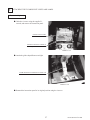
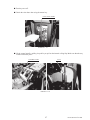
● Remove the 1 truss head screw that
fixes the GD-ROM drive lid (DISC
LID). And turn clockwise the lid to
remove.
TRUSS SCREW (1)
M3×8
PHOTO 6. 6 b
www.sauservice.com
30
● Set the GD-ROM disc onto the GD-ROM drive with its labeled side facing upward.
● Return the lid to its original place, and fix it with 1 truss head screw. Be careful not to fasten the screw
too tightly.
PHOTO 6. 6 c
TRUSS SCREW (1)
M3×8
TRUSS SCREW (2), black
M4×40, flat screw used
● Remove the side door R from the main
cabinet. Undo the 2 truss screws and open
the lock.
Unlock.
SIDE DOOR R
PHOTO 6. 6 d
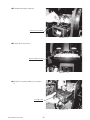
● Unplug the single connector that connects
the internal cabinet wire to the ASSY
MAIN BD inside the main cabinet.
CONNECTOR (1)
PHOTO 6. 6 e
31
www.sauservice.com
● Unplug the 3 connectors.
CONNECTOR (3)
PHOTO 6. 6 f
● Undo the fixing screws on the left and right
sides of the D-SUB connector that connects
to the side of the game board on the ASSY
MAIN BD. Unplug the USB connector.
USB CONNECTOR
D-SUB CONNECTOR
PHOTO 6. 6 g
● Remove the 2 screws that fix the ASSY
MAIN BD's base (a wooden base).
WING SCREW (2)
t
M4×30, flat washer used
PHOTO 6. 6 h
www.sauservice.com
32
● Take out the ASSY MAIN BD from
the main cabinet. Be careful not to
damage the wires in this instance.
ASSY MAIN BD
PHOTO 6. 6 i
● Place the ASSY MAIN BD on a flat horizontal surface.
● Using the 4 screws, fix the GD-
ROM drive onto the ASSY MAIN
BD.
SCREW (4)
t
M4×16, w/flat & sring washers
PHOTO 6. 6 j
● Insert both the GD cable connector (for data communication) and the power cord connector
(JST NH6P) into the GD-ROM drive. Be careful about an inserting direction in this instance.
Make sure that the connectors are inserted firmly and completely.
GD CABLE CONNECTOR
POWER CORD CONNECTOR
PHOTO 6. 6 k
33
www.sauservice.com
● Insert Key Chip straight into the hole on the Media Board side of upper part of the Game Board.
Be sure to check the alignment of the key chip and push it all the way in.
KEY CHIP
PHOTO 6. 6 l
● Affix the enclosed stickers to the Game Board. Affix the 843-****D-02 sticker to the Main Board and the
843-****B sticker to the Media Board. Place the both stickers on top of the stickers already affixed.
MEDIA BOARD
KEY CHIP
MAIN BOARD
FIG. 6. 6 c
PROJECTION
● Return the ASSY MAIN BD (now installed with the GD-ROM drive) into the main cabinet. Following
the above-described actions in a reverse order, fix the base, connect the connectors, and clamp the wires/
cables.
● Return the side door R to the main cabinet.
www.sauservice.com
34
7
WARNING!
POWER SUPPLY AND EARTH CONNECTION
● Be sure to independently use the power supply socket outlet equipped with an Earth
Leakage Breaker. Using a power supply without an Earth Leakage Breaker can
cause a fire when electric leakage occurs.
● Ensure that the "accurately grounded indoor earth terminal" and the earth wire cable
are available (except in the case where a power cord plug with earth is used). This
product is equipped with the earth terminal. Connect the earth terminal and the indoor earth terminal with the prepared cable. If the grounding work is not performed
appropriately, customers can be subjected to an electric shock, and the product's
functioning may not be stable.
● Ensure that the power cord and earth wire are not exposed on the surface (passage,
etc.). If exposed, they can be caught and are susceptible to damage. If damaged,
the cord and wire can cause electric shock and short circuit accidents. Ensure that
the wiring position is not in the customer's passage way or the wiring has protective
covering.
● After wiring power cord on the floor, be sure to protect the power cord. Exposed
power cord is susceptible to damage and causes an electric shock accident.
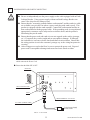
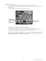
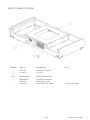
The AC Unit is located on back side of Cabinet. The AC Unit has Main SW, Earth Terminal and the Inlet
which connects the Power Cord.
● Ensure that the Main SW is OFF.
MAIN SW
Main SW off.
CIRCUIT PROTECTOR
INLET
EARTH TERMINAL <For Taiwan>
Connect with the indoor earth terminal.
AC CABLE (POWER CORD)
To the Power Supply
Socket outlet
FIG. 6. 7 a AC UNIT
35
www.sauservice.com
● Connect one end of the earth wire to the AC Unit
earth terminal, and the other end to the indoor earth
terminal. The AC Unit earth terminal has a Bolt and
Nut combination. Take off the Nut, pass the end of
earth wire through the Bolt, and fasten the Nut. <For
Taiwan>
*Note that the Earth Wire is incorporated in the
Power Cord for the Areas of AC 120 V (USA) and
AC 220~240 V, and therefore, this procedure is not
necessary.
Connect the Earth Wire
to the Earth Terminal.
FIG. 6. 7 b *Earth Wire Connection
● Firmly insert the power plug into
the socket outlet.
Insert the opposite side of Power
Cord plug to the AC Unit's connector ("INLET").
● Perform wiring for the Power Cord
and Earth Wire. Install protective
covering for the Power Cord and
Earth Wire.
WIRING COVER
FIG. 6. 7 c Connecting Power Cord and Earth Wire
In case the Power Plug is apt to come out of place, secure
the Power Cord to the periphery of the AC Unit with the
Cord Clamp (an accessory).
FIG. 6. 7 d HOW TO USE THE CORD CLAMP
www.sauservice.com
36
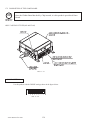
8
TURNING THE POWER ON
Turn the main switch on the AC unit on to turn the power on. When the power is turned on, the fluorescent lights in the billboard and instruction panel turn on. A few second later, the system startup screen is
displayed, then the waiting screen for customers (advertising screen) is displayed.
The time required for the advertising screen to appear can vary between several tens of seconds and a
few minutes. The time is not necessarily the same each time. This is due to the rechargeable battery in the
GD-ROM system, and does not represent a malfunction.
Audio begins playing from the speakers on the left and right sides of the main cabinet at the same time
the advertising screen is displayed. In addition, the halogen lamp, left and right controller holder LEDs,
and the LED under the IC card unit all light up. However, if the game has been configured to not play
sounds during advertising, then no sound is produced.
Even after you turn the power to this product off, the number of credits and ranking data are preserved.
However, the number of excess coins (the number of coins that have been inserted that do not add up to a
full credit) and bonus adder count data are not preserved.
FIG. 6. 8
37
www.sauservice.com
9
ASSEMBLY CHECK
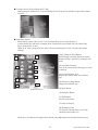
In the TEST MODE, ensure that the assembly has been made correctly and IC BD. is satisfactory (refer
to Section 9).
In the test mode, perform the following test:
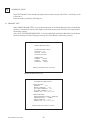
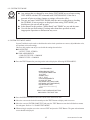
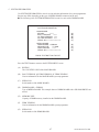
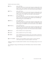
9-1 MEMORY TEST
When "MEDIA BOARD TEST" is selected from the System Test Mode Menu Screen the Game Board
memory is automatically tested. If the display beside each memory reads "GOOD", the Game Board is
functioning correctly.
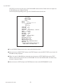
Also, when "SYSTEM INFORMATION" is selected, Main Board and Media Board data for the Game
Board are displayed. If data is displayed correctly, the Game Board is functioning correctly.
MEDIA BOARD TEST
DIMM BOARD(TYPE3)
VERSION ****
STATUS GOOD
CHECKING 100%
DIMM TEST
DIMM0
GOOD
DIMM1
NONE
GD-ROM
GOOD
PRESS TEST BUTTON TO EXIT
MEDIA BOARD TEST screen
SYSTEM INFORMATION
MAIN BOARD
REGION
****
BOOT VERSION
****
QC FIRM VERSION ****
SC FIRM VERSION ****
SERIAL NO. ***************
MEDIA BOARD
DIMM BOARD(TYPE3) + GDROM
MEMORY SIZE
512MB
FIRM VERSION
****
SERIAL NO. ***************
PRESS TEST BUTTON TO EXIT
SYSTEM INFORMATION screen
www.sauservice.com
38
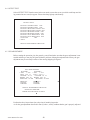
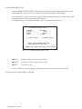
9-2 C.R.T. TEST
C.R.T. TEST 1/2
1
In the TEST mode menu, selecting C.R.T.
TEST allows the screen (on which the projector is tested) to be displayed. Although
the projector adjustments have been made at
the time of shipment from the factory, make
judgment as to whether an adjustment is
needed by watching the test mode screen. If
it is necessary, adjust the projector by referring to Section 12.
32
RED
GREEN
BLUE
WHITE
PRESS TEST BUTTON TO CONTINUE
C.R.T. TEST 2/2
PRESS TEST BUTTON TO EXIT
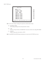
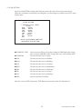
9-3 INPUT TEST
INPUT TEST
Selecting the INPUT TEST on the game test
mode menu screen causes the screen (on
which each switch is tested) to be displayed.
Press each switch. If the display beside each
switch indicates "ON," the switch and wiring connections are satisfactory.
PLAYER
1
2
TRIGGER OFF OFF
ACTION OFF OFF
CHANGE OFF OFF
CARD IN OFF OFF
GUN-X
00H 00H
GUN-Y
00H 00H
SCREEN OUT OUT
START
OFF OFF
SERVICE
TEST
OFF
OFF
PRESS TEST AND SERVICE BUTTON TO EXIT
39
www.sauservice.com
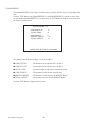
9-4 OUTPUT TEST
Select OUTPUT TEST from the menu in the test mode to cause the screen (on which each lamp and wiring connections are tested) to appear. Ensure that lamp light up satisfactorily.
OUTPUT TEST
PLAYER 1 START LAMP OFF
PLAYER 2 START LAMP OFF
PLAYER 1 HALOGEN LAMP OFF
PLAYER 2 HALOGEN LAMP OFF
PLAYER 1 HOLDER LAMP OFF
PLAYER 2 HOLDER LAMP OFF
PLAYER 1 GUN REACTION OFF
PLAYER 2 GUN REACTION OFF
COIN LED
OFF
-> EXIT
SELECT WITH SERVICE BUTTON
9-5 GUN ADJUSTMENT
Before starting the operation, play the game by yourself and make sure that the gun readjustment is not
needed and that you can play the game without a problem. Although completed at the factory, the gun
adjustment may be necessary because of the moving/shipping divergence.
●
GUN ADJUSTMENT
PLAYER 1
PLAYER 2
-> TOP
5 233 -> TOP
5 233
LEFT -318 17
LEFT -318 17
CENTER -10 15
CENTER -10 15
RIGHT 242 34
RIGHT 242 34
BOTTOM -10 -204
BOTTOM -10 -204
●
DEFAULT
CANCEL
CURSOR
DEFAULT
●
CANCEL
CURSOR
●
SELECT WITH SERVICE BUTTON
AND PULL TRIGGER
PRESS TEST BUTTON TO EXIT
●
Perform the above inspections also at the time of monthly inspection.
As for the gun adjustment described in Part (5) above, weekly confirm that the gun is properly adjusted.
www.sauservice.com
40
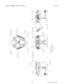
Interference Prevention Wiring
● In order to prevent electric shock and short circuit hazards, be sure to turn power off
before performing work.
● Be careful not to damage the wires. Damaged wires may cause electric shock or
short circuit or present a fire risk.
● Do not expose the IC BD, etc. without a good reason. Failure to observe this can
cause electric shock hazard or malfunctioning.
● Work should be performed by the Location's Maintenance Man or technical personnel. Performing work by those who do not have technical knowledge and expertise
can cause electric shock accident or malfunctioning.
WARNING!
When the game machines of a same or similar type are installed side by side, their sensors may interfere
with each other. To reject the interference, follow the procedure below.
The following game machines employ a same or similar type of sensor. If interference happens to the
sensors, operation of the games may be mutually disturbed.
●
●
●
●
●
●
●
●
●
●
●
●
THE HOUSE OF THE DEAD 2, U/R type, DX type and Super DX type
DEATH CRIMSON, U/R type and DX type
THE LOST WORLD, U/R type, DX type and Super DX type
BRAVE FIRE FIGHTERS
SAMBA DE AMIGO
CONFIDENTIAL MISSION, U/R type and DX type
SHAKATTO TAMBOURINE
LUPIN THE 3RD THE SHOOTING, U/R type and DX type
THE MAZE OF THE KINGS, U/R type and DX type
THE HOUSE OF THE DEAD 3, U/R type and DX type
VIRTUA COP 3, U/R type and DX type
GHOST SQUAD, U/R type and DX type
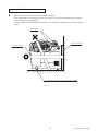
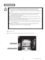
● Turn the power off.
● Undo the 2 truss screws and remove the side door
L from the main cabinet.
TRUSS SCREW (2), black T
M4×40, flat washer used
SIDE DOOR L
PHOTO 6. 9 a
41
www.sauservice.com
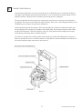
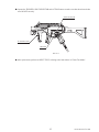
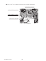
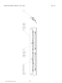
● The interference prevention wire is connected to the sensor board on the lower right side.
If multiple units of the same game are installed side by side, make sure that the game units that
are connected to the interference prevention wires are arranged so that they alternate with the
units that are not connected.
INTERFERENCE PREVENTION WIRING
CTF-60013
PHOTO 6. 9 b
www.sauservice.com
42
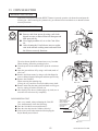
7. PRECAUTIONS WHEN MOVING THE MACHINE
WARNING!
CAUTION!
● When moving the machine, be sure to pull out the plug from the power supply. Moving the machine with the plug as is inserted can cause the power cord to be damaged
and could result in a fire and or electric shock.
● When moving the machine on the floor, retract the Adjusters and ensure that Casters
make contact with the floor. During transportation, pay careful attention so that Casters do not tread power cords and earth wires. Damaging the power cords can cause
an electric shock and or short circuit.
● In places where step-like grade differences exist, be sure to separate the PTV, PTV
Cabinet, and the Controller Cabinet. Inclining the PTV as is mounted on the PTV
Cabinet can cause the PTV to fall off from the Base and result in injury.
● When lifting the cabinet, be sure to hold the grip portions or bottom part. Lifting the
cabinet by holding other portions can damage parts and installation portions due to
the empty weight of the cabinet, and cause personal injury.
● When moving the PTV, do not push it from the rear side. Push it from sideways.
Pushing the PTV from the rear side can have the PTV fall down, causing personal
injury etc. In case the floor has slanted surfaces or step-like differences, be sure to
move the machine by 2 or more persons.
● When the Cabinet is disassembled, the detached Controller Cabinet may be unstable.
If it is carelessly pushed, it can fall and cause accidents. When the Control Cabinet
is detached, place it in on a level surface and be careful not to tip it right or left when
moving it.
● Do not move the product with a GD-ROM disc inside. Remove the
GD-ROM disc before moving the product.
Failure to observe this instruction may cause the GD-ROM disc and/or GD-ROM
drive to be damaged.
● Do not hold or press the plastic parts as indicated by the Figure 7c. Failure to observe this instruction may break the parts, and eventually the broken pieces may
cause a personal injury.
● When moving the machine, be sure to remove the foot pedals. Moving with the foot
pedals may cause an accident, and deform or damage the part/floor.
43
www.sauservice.com
Do not push PTV from the back. Pushing the PTV
from the back can cause the PTV to fall down. Push
it from the side.
Have caster make contact with the floor.
t
FIG. 7 a
GRIP PORTION
When transporting the product in
places with steps or step-like differences in grade, disassemble into each
unit before transporting.
FIG. 7 b
Do not hold press these hatched
parts to move the product.
FIG. 7 c
www.sauservice.com
44
Cautions When Transporting the Machine
●
Do not tie machine down using Plastic Parts as an anchor.
When using straps or tie downs (rope etc), use caution. Use protective material where tie downs
contact machine to avoid damage.
To keep machine from shifting during transport, be certain all leg adjusters are in contact with the
pallet.
Plastic parts
Protective material
Protective material
Be certain all leg adjusters are in contact with the pallet.
FIG. d
45
www.sauservice.com
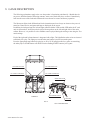
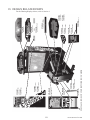
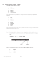
8. GAME DESCRIPTION
The following explanations apply to the case the product is functioning satisfactorily. Should there be
any moves different from the following contents, some sort of faults may have occurred. Immediately
look into the cause of the fault and eliminate the cause thereof to ensure satisfactory operation.
The fluorescent lights in the billboard and in the instruction panel are always on whenever the power is
turned on. Demo movies and game rankings are displayed on the screen.
In addition, the halogen lamp, the left and right controller holder LEDs and the LED under the IC card
unit are all turned on. Audio may also be played from speakers on the left and right sides of the main
cabinet. However, it is possible to select whether sound is played during advertising or not using the Test
mode settings.
Each of the right and left start buttons is integrated with a light. The light flashes when coins are inserted
sufficiently for a play. The light goes out when the start button is pressed to start the game.
Press the appropriate start button to begin play as 1P or 2P. If enough credits for a game are remaining,
the other player's START button will flash. Press the flashing START button to join a game.
2P START BUTTON
1P START BUTTON
1P GAME CONTROLS
2P GAME CONTROLS
SHOT SELECTOR
ACTION BUTTON
CABINET
TRIGGER
FIG. 8
www.sauservice.com
46
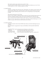
GUN CONTROLLER
This manual explains the game details when used with IC Cards.
The game content for cabinets without IC Card Units or games played without the use of an IC Card
("Only without the IC Card") is explained separately as needed.
(1) GAME OUTLINE
The player is a member of the special forces unit, "Ghost Squad", out to suppress vicious terrorists. Each
mission contains multiple routes, allowing the player to choose how to proceed. Special events occur
throughout the game depending on the route chosen, such as securing hostages or providing friendly
cover fire.
This game also supports the use of IC Cards.
Players can enjoy a number of additional features recorded on IC Cards, including character name, score,
experience accumulation, changes in rank, item collection, and added mission routes and events.
Plus, by using the password displayed following a game, players can also access an Internet Ranking.
[When no IC Card is being used, the recording of player information and Internet Ranking access are not
available. Also, play will be limited to certain mission routes and items.]
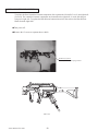
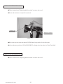
(2) GAME CONTROLS
The game is controlled with the cabinet START buttons and the provided sub-machinegun-style gun
controllers.
Each gun controller is equipped with 3 buttons, the TRIGGER, ACTION and SHOT SELECTOR
buttons.
• START BUTTON : Used for starting the game and skipping event descriptions.
• TRIGGER
: Used for firing (shooting bullets) and panel selection.
• ACTION BUTTON
: Used during events and for skipping demo scenes.
• SHOT SELECTOR
: Used to switch between firing modes (single shot, 3-shot burst, full
auto).
PLAYER 1 START BUTTON
SHOT SELECTOR
ACTION BUTTON
TRIGGER
PLAYER 2
START BUTTON
❃ PLAYER 1 CARD SLOT
❃ PLAYER 2 CARD SLOT
[❃: Only for cabinets equipped with IC Card Units.]
47
www.sauservice.com
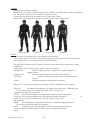
(3) CHARACTERS
● Alpha Unit
The Alpha Unit are the main characters in the game and are young hot-shot members of "Ghost Squad",
an unofficial unit of the anti-terrorist group, "M.O.P." (Multiple-Operation-Program)
● Fellow M.O.P. Members
The Commander provides radio backup and pertinent advice to the Alpha Unit.
Also assisting the Alpha Unit in operations are Bravo Unit and Charlie Unit. These two units assist the
players in suppressing the terrorist threat.
COMMANNDER
www.sauservice.com
UNIT BRAVO
48
UNIT CHARLIE
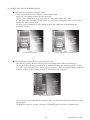
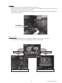
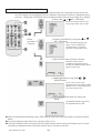
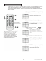
(4) GAME FLOW AND ON-SCREEN DISPLAY
● Card Insertion Screen [Only with the IC Card]
The IC Card Insertion Screen is displayed when starting a game.
Insert an IC Card into the card slot to read stored data.
To play a game without using an IC Card, select the "Start game without card." panel.
IC Card updates are also handled on this screen. Insert an old IC Card together with a new IC Card to
transfer play data to the new card.
The game can be started directly after completing the update. (❃Refer to the additional update
description section.)
IC Card Insertion Screen
Screen following IC Card insertion
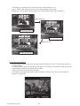
● Player Information Display Screen [Only with the IC Card]
After starting a game with an IC Card, the player information read from the card is displayed.
On this screen, the following information can be confirmed: Player name, remaining number of card
uses, rank, level, experience points, number of plays, top score, number of weapons attained, number of
costumes attained, weapon currently being used, costume currently being worn.
Player Information Screen
On this screen, select GAME START to begin the game with the same weapon and costume used in the
previous game.
To change the weapon or costume, select the CUSTOMIZE panel to go to the Customize Screen.
49
www.sauservice.com
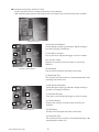
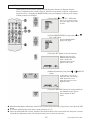
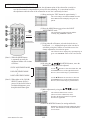
● Customize Screen [Only with the IC Card]
On the Customize Screen, weapons and costumes can be changed.
With sufficient game progress, name change and screen display type selection also become available.
Customize Screen
(A)
(D)
(C)
(A)(B) Item Scroll Buttons
Scrolls through costume type indicators. Rapid scrolling is
possible by keeping it held down.
(C) Selectable Costumes
Line up the cursor and pull the trigger to select a costume.
(E)
(B)
(F)
Customize Select Screen
(D) Current Costume
Displays the currently selected costume as worn by the
character.
(E) OK Button
Sets the selected costume and returns to the menu.
(F) Remaining Time
The currently selected costume is selected automatically if the
remaining time reaches zero.
(G)(H) Item Scroll Buttons
Scrolls through weapon type indicators. Rapid scrolling is
possible by keeping it held down.
(G)
(I)
(H)
(J)
(I) Selectable Weapons
Line up the cursor and pull the trigger to select a weapon.
(K)
(J) Current Weapon
Displays the currently selected weapon as held by the
character.
(L)
Select Weapon Screen
(K) OK Button
Sets the selected weapon and returns to the menu.
(L) Remaining Time
The currently selected weapon is selected automatically if the
remaining time reaches zero.
www.sauservice.com
50
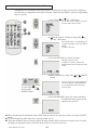
● Customize Screen [Only without the IC Card]
Starting the game without an IC Card will display the following screen and allow weapon and costume
selection.
● Name Entry Screen
When starting a game with a new IC Card, the Name Entry Screen is first displayed.
A name chosen once can later be changed on the Customize Screen. In both cases, the Name Entry
Screen shown below is used.
[When no IC Card is being used, this name will be used to display the score if it makes the cabinet
ranking.]
(N)(O) Character Scroll Buttons
Scroll through selectable characters (letters).
Rapid scrolling is possible by keeping it held
down.
(Q)
(N)
(R)
(P)
(P) Selectable Characters
Line up the cursor and pull the trigger to select
a character.
(S)
(T)
(Q) Current Character Type
Displays the current name entry character
type.
(U)
(O)
(V)
(R) Character Change Button
Changes the character type.
(W)
(S) Space Button
Name Entry Screen
(T) Backspace Button
(U) END Button
Sets the entered name.
(V) Name as Entered
(W) Remaining Time
The currently entered name is used if the
remaining time reaches zero.
Names up to 16 characters in length can be entered, using alphanumeric and symbol character types.
51
www.sauservice.com
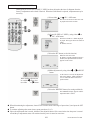
● Gun Controller Explanation Screen
Exiting the Customize Menu plays the demo explaining how to use the gun controller.
This explains the shooting stance, and how to use the SHOT SELECTOR and ACTION button.
It is possible to skip this explanation with the START button.
Gun Controller Explanation Screen
● Gun Controller Calibration Screen
If the CALIBRATION setting in the game Test Mode is turned on, this screen is displayed before starting
the game.
Holding the gun controller correctly, aim at the target bulls-eye and pull the trigger to calibrate the gun.
Press the START button to exit the Calibration Screen without waiting for the time limit to run out.
Gun Controller Calibration Screen
www.sauservice.com
52
● Mission Select Screen
On this screen, the player selects which mission to play from 3 available missions.
Playing one mission all the way to the end displays this screen once again, allowing the player to select
another mission.
A mission played once cannot be played again in the same game.
Mission
Achievement
Rate
Mission Level
Mission Select Screen
The Mission Level is displayed on the Mission Select Screen.
Using an IC Card, the Mission Level will increase each time the boss is defeated.
To replay missions at a lower level, line up the curser with the Mission Level display and push the
ACTION button. By changing the level, it is possible to play at the desired level.
[When no IC Card is being used, only Mission Level 1 to 4 can be selected from the beginning, and the
Mission Achievement Rate is not displayed. There are no differences in game characteristics such as
difficulty, game play changes, or the number of game events.]
53
www.sauservice.com
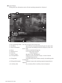
● In-game Display
During game play, information such as life and remaining ammunition is displayed.
(4)
(1)
(5)
(2)
(3)
(7)
(6)
(8)
(9)
(10)
(11)
(1) Life (remaining health) : The color will grow red as it nears zero.
(2) GS Meter
: Special Points accumulated during the game are shown here.
(3) Player Information
: Player name and ranking insignia are displayed. [Only with
the IC Card]
(4) Score
: Points accumulated during play.
(5) Mission Level
: Level of the current mission.
(6) Terrorist
: Find and suppress!
(7) Fellow Troops
: Members of the "Ghost Squad".
(8) Correspondence
: Support requests from fellow troops, or advice from the
Commander appears here.
(9) Firing Mode
: Selectable firing modes and the currently selected firing mode
are displayed.
(10) Weapon Information
: Equipped weapon and remaining magazine ammunition are
displayed.
(11) Auxiliary Item
: Any currently effective auxiliary items are displayed.
www.sauservice.com
54
● Mission Results Screen [Only with the IC Card]
After either successfully completing a single mission or dying partway, the Mission Result Screen is
displayed.
Mission information, including the route taken or event results, can be confirmed on this screen.
This screen also displays a notification if the Mission Level has increased.
• Box showing "???"
: Event to debut at a higher Mission Level.
• Gray, labeled box : Not yet played despite a sufficient Mission Level.
• Blue box
: Already played, but not cleared.
• Green box
: Cleared sometime in the past.
● Game Results [Only with the IC Card]
Playing a game with an IC Card allows viewing of the game's play results following the game.
Any notifications of leveling up, rank promotion, obtaining weapons/costumes, and so on, are displayed
on this screen.
Game Results Screen
Nice job! You have been promoted!
55
www.sauservice.com
(5) GAME RULES AND GAMEPLAY
Life
During play, the player's life is displayed at the top part of the screen.
Life is diminished by enemy attack or accidental fire on hostages.
Once the player's life runs out, play stops.
The amount of life to start a game with can be configured in Test Mode settings.
Changing life settings will not affect the length of the life gauge. Instead, the amount of life lost when
receiving damage changes, effectively varying the number of sustainable enemy hits.
�Refer to the "LIFE" setting of the "GAME ASSIGNMENTS" section in "Test Mode".�
Continue and Game Over
The option to "Continue" is available when the player's life runs out.
The START button can be used to continue the game, as long as there are credits remaining.
When using an IC Card, each "Continue" deducts from the number of remaining card uses.
Not continuing results in "Game Over".
When using an IC Card, game results are displayed following the game, showing experience increases,
rank promotions, and so on.
GS Meter
The GS Meter measures the value of the player's special force performance.
For example, pulling off a special shot ("GOOD SHOT", "QUICK SHOT", etc.) or successfully
completing an event raises the meter, while shooting fellow troops or hostages lowers the meter.
When the GS Meter reaches its maximum level, the current weapon receives an upgrade.
Building up the GS Meter also increases the amount of experience gained following a game.
Reload
When a magazine is empty, reloading is executed by simply aiming the gun controller outside of the
screen.
At that time it is not necessary to press the trigger or any other buttons.
The time it takes between reloading and being able to shoot again varies between weapons.
www.sauservice.com
56
E-Marker
When discovered, the terrorists commence fire upon the player.
However, not all shots result in injury. An "E-Marker" will be displayed on any enemy whose shots will
inflict damage, serving as a warning to the player.
When under fire from multiple enemies, first defeating enemies marked with an E-Marker should help
the player avoid damage.
E-Marker
Tactic Selection
Proceeding through the game, "Tactic Selection" panels (as shown below) will appear.
The mission route will vary greatly depending on which panel is chosen.
Choosing Right Panel
Choosing Left Panel
A "Remove the Bomb" event occurs!
A "Save the Hostages" event occurs!
57
www.sauservice.com
The number of selectable tactics will increase along with the Mission Level.
Also, a "NEW" label will be displayed on any newly appearing tactics panels.
[When no IC Card is being used, the number of Tactics Selection panels will not increase.]
Mission level-up
Initially only one route
Branching routes
Mission level-up
Another branching route
Events (Special Operations)
Besides normal terrorist suppression, this game includes additional "events", such as bomb removal or
securing hostages.
A certain number of events are initially open for play, but by using an IC Card and leveling-up missions,
a large number of additional events become available.
Some events allow use of specialized weapons.
For example, when attacking the enemy from a distance in a Sniper event, the weapon temporarily
changes to a sniper rifle.
www.sauservice.com
58
Auxiliary Items
Auxiliary items appear in certain situations during the game.
There are two types of auxiliary items—items that are put to use and disappear immediately after picking
up, and those that are stocked and continue to be effective over time. The latter type can be used only one
at a time.
Some auxiliary items can be taken advantage of only when combined with certain weapons.
For example, the "Compensator" is effective only when using weapons that produce a bullet spread
effect.
The auxiliary items appearing in this game consist of the following 7 types.
First-Aid Kit
: Restores 1 life unit.
Dot Sight
: Displays the gun's sight reticule as an illuminated point.
Hi-cap Magazine : Doubles magazine capacity.
Compensator
: Eliminates bullet spread effects.
Body Armor I
: Halves the amount of damage taken for up to 2 hits.
Body Armor II
: Halves the amount of damage taken for up to 4 hits.
Medal
: Increases experience points acquired following the game.
[When no IC Card is being used, it boosts the GS Meter.]
Experience Points
Experience points are accumulated during game play when playing with an IC Card.
The amount of experience points accumulated during play are determined by score, GS Meter level,
the number of medals, and game progress. These points are awarded to the player on the Game Results
Screen following the game.
The player is leveled up after reaching a certain experience level. Depending on the level increase,
players are rewarded with promotions and new weapons. Any new weapons can be used from the next
play.
[When no IC Card is being used, there are no experience points.]
Rank and Promotion
Ranks serve as a comprehensive evaluation of the player's ability.
If certain conditions are met when leveling up, the player's rank increases by a level. This is referred to as
"promotion".
Promotions open up new costumes and high-level, rare weapons that can be used from the next play.
[When no IC Card is being used, the rank insignia is decided by the player's score.]
59
www.sauservice.com
Costumes
This game has 14 different costumes.
Initially only 2 are available ("GHOST SQUAD" and "JUNGLE"), but that number increases with further
play. The chosen costume can be viewed during in-game cut scenes.
Costumes have no direct effect on damage, score, or other game content.
[When no IC Card is being used, costumes are chosen from the 4 types shown below.]
GHOST SQUAD
JUNGLE
TOUGH GUY
COWBOY
Weapons
As the player's level and rank go up, new weapons become available.
After a weapon has been acquired, it can be selected from the Customize Screen before starting a game.
Once equipped, however, a weapon cannot be changed during play.
This game has 25 different types of weapons, each with varying characteristics and auxiliary weapon
compatibility.
- Machinegun class : A typical weapon, capable of rapid-fire shooting.
- Shotgun class
: Blasts covering a wide area, a single shot is capable of taking out
multiple enemies.
- Handgun class
: Requires a high learning curve, suitable for expert players.
- Rifle class
: Capable of piercing walls and obstacles, can take out hidden
enemies.
- Others
: Weapons not fitting in any of the above categories.
[When no IC Card is being used, weapons are chosen from the 4 shown below before a game.]
"XM-2119"
: A standard sub-machinegun. Can toggle between Semi-auto, 3-Shot Burst, and
Full-auto firing modes to best match the situation. There is, however, an
ammunition restriction on Full-auto fire.
"TK1B" : A powerful machinegun. It has high firepower and no Full-auto ammunition
restriction. It is also has penetration power, making hidden enemies vulnerable to
fire. Its lack of accuracy from bullet spread is its main weakness, along with a
long reload time.
"P44M" : This handgun has no rapid-fire ability, but proves reliable in targeting enemies. It
is extremely powerful and capable of penetration.
"M4E"
: A shotgun, capable of hitting multiple enemies with a single shot. Despite its
power, the danger of hitting hostages or fellow troops with friendly fire warrants
caution.
www.sauservice.com
60
its
Mid-game Entry
It is possible for an additional player to join later, even if a player is in the middle of play. If the
necessary number of credits has been inserted, a message (as shown below) is displayed on the bottom
part of the screen.
Pressing the START button at this point will commence entry without the use of an IC Card.
By first inserting a card before pressing the START button, play will commence using that IC Card.
In that case, the player will be equipped with the same weapon and costume used in the previous play.
Mid-game Termination
In a 2-player game, if only 1 player (using an IC Card) ends the game, that player's information
(experience points, rank, high score, etc.) is updated even though the Game Results Screen is NOT
displayed.
Details can be confirmed on the Player Data Screen before starting the next game.
61
www.sauservice.com
(6) IC CARDS [ONLY WITH THE IC CARD]
● Number of Uses
The number of uses per IC Card is 100.
This number includes expenditure for starting or continuing games.
An IC Card with 0 remaining uses cannot be used to start a game.
However, if the remaining uses reaches 0 during play, it is possible to continue a game. A game can be
continued until either the player ends the game (decides not to continue after running out of life) or all
missions have been completed.
● Updating (Data Transfer)
If an IC Card's remaining uses reaches 0, its data can be transferred to a new IC Card, allowing another
100 uses. This operation is referred to as "updating".
Updating is handled on the IC Card Insertion Screen when beginning a game.
Inserting the old card and a new, unused card together at the same time while this screen is displayed
transfers saved data to the new card.
It is possible to update any card, regardless of the number of remaining uses.
However, even if the old card has remaining uses, the new, updated IC Card will always start with 100
remaining uses.
● Card Recovery
If the data stored on an IC Card happens to be damaged, it may be possible to restore that data using Card
Recovery.
To enter Card Recovery, on the advertisement screen, press the TEST button while holding down the
PLAYER 1 and PLAYER 2 START buttons at the same time.
In Card Recovery, use the PLAYER 2 START button to move between panels and the PLAYER 1 START
button to select. Selecting the "Try to restore your card." panel begins automatic data restoration.
Be warned that Card Recovery is not always successful in restoring data.
If recovery fails, the error message, "This card cannot be initialized." is displayed.
Failed recovery error message
Card Recovery
www.sauservice.com
62
9. EXPLANATION OF TEST AND DATA DISPLAY
By operating the switch unit, periodically perform the tests and data check. When installing the machine
initially or collecting cash, or when the machine does not function correctly, perform checking in
accordance with the explanations given in this section.
The following shows tests and modes that should be utilized as applicable.
This product's basic system consists of the Chihiro game board and the GD-ROM drive. The system
enables you to play several games one after the other just by changing a GD-ROM disc that is to be set
on the GD-ROM drive.
The product supports, therefore, the following 2 test modes:
(1) System test mode for an automatic self-diagnostic test (generally used by every product that contains
the basic system) and a coin assignment (specifically used by this product) and
(2) Game test mode for testing the input/output control devices and setting the difficulty level
(specifically used by this product).
TABLE 9 EXPLANATION OF TEST MODE
ITEMS
DESCRIPTION
REFERENCE
SECTIONS
INSTALLATION
OF MACHINE
When the machine is installed, perform the following:
1. Check to ensure each is the standard setting at shipment.
2. Check each Input equipment in the INPUT TEST mode.
3. Check each Output equipment in the OUTPUT TEST mode.
4. Test on-IC-Board IC's in the self-test mode.
MEMORY TEST
This test is automatically executed by selecting MEDIA
BOARD TEST or SYSTEM INFORMATION in the Menu
mode.
PERIODIC
SERVICING
Periodically perform the following:
1. MEMORY TEST
2. Ascertain each setting.
3. To test each Input equipment in the INPUT TEST mode.
4. To test each Output equipment in the OUTPUT TEST mode.
CONTROL
SYSTEM
1. To check each Input equipment in the INPUT TEST mode.
2. Adjust or replace each Input equipment.
3. If the problem still remains unsolved, check each equipment's
mechanism movements.
MONITOR
In the Monitor Adjustment mode, check to see if Monitor (Projector) adjustments are appropriate.
9-2F
12
IC BOARD
MEMORY TEST
9-2B, C
DATA CHECK
Check such data as game play time and histogram to adjust the
difficulty level, etc.
9-3G
63
9-3C
9-3A
9-3B
9-2B, C
9-2B, C
9-2B, C
9-3C, D
9-3A
9-3B
9-3A
9-3D
10
www.sauservice.com
9-1 SWITCH UNIT AND COIN METER
Never touch places other than those specified. Touching places not specified can cause
electric shock and short circuit accidents.
WARNING!
STOP
IMPORTANT!
● Adjust the sound to the optimum volume, taking into consideration the
environmental requirements of the installation location.
● Removing the Coin Meter circuitry renders the game inoperable.
SWITCH UNIT
Open the coin chute door, and the switch unit shown will appear.
The functioning of each SW is as follows:
TEST BUTTON
SERVICE BUTTON
SOUND VOLUME SWITCH
FIG. 9. 1 a SWITCH UNIT
● SOUND VOLUME SWITCH:
Adjusts sound volume for all of the machines' Speakers.
● SERVICE BUTTON:
Gives credits without registering on the coin meter.
● TEST BUTTON:
For the handling of the test button, refer to the following pages.
(SOUND VOLUME)
(SERVICE)
(TEST)
COIN METER
Open the Cashbox Door by using the key to have
the Coin Meter appear underneath the Cashbox.
COIN METER
FIG. 9. 1 b
www.sauservice.com
64
9-2 SYSTEM TEST MODE
STOP
Any settings that are changed by users during TEST MODE are saved upon exiting
TEST MODE with the EXIT command in the SYSTEM MENU. If the unit is
powered off prior to exiting, changes to settings will not take effect.
● You may not enter GAME TEST MODE while the unit is reading from or checking
the GD-ROM. If error messages are displayed when exiting TEST MODE, you
should power the unit off and on again.
● In the manual for this product, "Media Board" and "DIMM" are one and the same.
● Use with the specified settings. If settings other than those specified are used,
inappropriate operations or malfunction may occur.
●
IMPORTANT!
A. SYSTEM TEST MENU MODE
System Test Mode can be used to check that the main circuit operations are correct, adjust Monitor color,
and perform coin/credit settings.
However, this product can only be used with the settings shown below.
● SOUND TEST
- OUTPUT TYPE: STEREO
● COIN ASSIGNMENTS
- COIN CHUTE TYPE: COMMON
- SERVICE TYPE: COMMON
● Press the TEST Button after powering on the unit to display the following SYSTEM MENU.
SYSTEM MENU
MEDIA BOARD TEST
SYSTEM INFORMATION
JVS TEST
SOUND TEST
C.R.T. TEST
COIN ASSIGNMENTS
CLOCK SETTING
NETWORK SETTING(CORE)
NETWORK SETTING(MEDIA)
ENTER GAME TEST
[*******************]
→EXIT
SELECT WITH SERVICE BUTTON
AND PRESS TEST BUTTON
● Press the SERVICE Button to move the cursor to the desired test item.
● Move the cursor to the desired item and press the TEST Button to display each test screen.
● Move the cursor to ENTER GAME TEST and press the TEST Button to enter the individual test menus
for each game. Refer to "9-3 GAME TEST MODE".
● When testing is complete, move the cursor to EXIT and press the TEST Button. The game advertisement
screen should be displayed.
65
www.sauservice.com
B. MEDIA BOARD TEST
STOP
IMPORTANT!
Powering off the system during the MEDIA BOARD TEST with a DIMM BOARD will
erase the game programme data. It may be necessary to reload the data.
Always wait for the test to complete before attempting to exit.
MEDIA BOARD TEST is used to check the memory and IC on the MEDIA BOARD connected to the
Chihiro. Test screens and test times may differ depending on the type of MEDIA BOARD connected to
the unit.
1- The following is the MEDIA BOARD TEST screen for a unit with a DIMM BOARD.
MEDIA BOARD TEST
DIMM BOARD(TYPE3)
VERSION ****
STATUS GOOD
CHECKING 100%
DIMM TEST
DIMM0
GOOD
DIMM1
NONE
GD-ROM
GOOD
PRESS TEST BUTTON TO EXIT
2- MEDIA BOARD TEST begins immediately upon entering this test mode.
3- If "GOOD" is displayed to the right of each item, the MEDIA BOARD components are functioning
properly.
4- After the test is complete, move the cursor to EXIT and press the TEST Button to return to the SYSTEM
MENU screen.
www.sauservice.com
66
C. SYSTEM INFORMATION
Use SYSTEM INFORMATION to check version and other information for system programmes.
Screens may differ depending on the type of MEDIA BOARD connected to the unit.
● The following is the SYSTEM INFORMATION screen for a unit with a DIMM BOARD.
SYSTEM INFORMATION
MAIN BOARD
REGION
****
BOOT VERSION
****
QC FIRM VERSION ****
SC FIRM VERSION ****
SERIAL NO. ***************
(A)
(B)
(B)
(B)
(C)
MEDIA BOARD
DIMM BOARD + GDROM
MEMORY SIZE
512MB
FIRM VERSION
****
SERIAL NO. ***************
(D)
(E)
(F)
(G)
PRESS TEST BUTTON TO EXIT
Press the TEST Button to return to the SYSTEM MENU screen.
(A)
REGION
The COUNTRY CODE of the MAIN BOARD.
(B)
BOOT VERSION, QC FIRM VERSION, SC FIRM VERSION
Version information for the MAIN BOARD system programmes.
(C)
SERIAL NO.
Serial number of the MAIN BOARD.
(D)
DIMM BOARD + GDROM
Type of MEDIA BOARD. This example shows a DIMM BOARD with a GD-ROM DRIVE connected.
(E)
MEMORY SIZE
Capacity of DIMM memory installed on the DIMM BOARD.
(F)
FIRM VERSION
Version information for the DIMM BOARD system programme.
(G)
SERIAL NO.
Serial number of the DIMM BOARD.
67
www.sauservice.com
D. JVS TEST
JVS TEST is used to verify the specs of the I/O BOARD connected to the Chihiro and to run input tests.
I/O BOARD specs are displayed initially.
Screens may differ depending on the type of I/O BOARD connected to the unit.
JVS TEST
INPUT TEST
NEXT NODE
→EXIT
NODE
****
NAME
****************
I/O BD JVS
Ver****
*********
CMD VER 1.1
JVS VER 2.0
COM VER 1.0
SWITCH
2 PLAYER(S) 13 BITS
COIN
2 SLOT
ANALOG
8 CH
ROTARY
0 CH
KEYCODE 0
SCREEN
X:0 Y:0 CH:0
CARD
0 SLOT
HOPPER OUT 0 CH
DRIVER OUT 6 CH
ANALOG OUT 0 CH
CHARACTER CHARA:0 LINE:0
BACKUP
0
SELECT WITH SERVICE BUTTON
AND PRESS TEST BUTTON
● Use the SERVICE Button to move the cursor to the desired test item.
● Move the cursor to INPUT TEST and press the TEST Button to enter the INPUT TEST screen for the I/O
BOARD currently displayed.
● When 2 or more I/O BOARDS are connected, move the cursor to NEXT NODE and press the TEST
Button to enter the test screen for the next I/O BOARD. The lower the NODE number, the further away
the node is from the Chihiro.
● Move the cursor to EXIT and press the TEST Button to return to the SYSTEM MENU screen.
www.sauservice.com
68
INPUT TEST Screen
JVS TEST
INPUT TEST
NODE
1/1
SYSTEM
00
PLAYER 1 0000
PLAYER 2 0000
COIN 1
0000
COIN 2
0000
ANALOG 1 0000
ANALOG 2 0000
ANALOG 3 0000
ANALOG 4 0000
ANALOG 5 0000
ANALOG 6 0000
ANALOG 7 0000
ANALOG 8 0000
(A)
(A)
(A)
(B)
(B)
(C)
(C)
(C)
(C)
(C)
(C)
(C)
(C)
PRESS TEST AND SERVICE BUTTON TO EXIT
● On-screen values change according to the input from switches and the volume.
(A)
SYSTEM, PLAYER
Values change with input from control panel/other switches.
(B)
COIN
Increases with input from the COIN SWITCH. The count is cleared when exiting TEST MODE.
(C)
ANALOG
Displays analog values from "0000" to "FFFF".
● Press the SERVICE and TEST Buttons simultaneously to return to the JVS TEST main screen.
69
www.sauservice.com
E. SOUND TEST
Use SOUND TEST to test sound output and to select the stereo/mono/surround setting.
SOUND TEST
OUTPUT TYPE
RIGHT SPEAKER
LEFT SPEAKER
→EXIT
STEREO
OFF
OFF
(A)
(B)
(B)
SELECT WITH SERVICE BUTTON
AND PRESS TEST BUTTON
● Use the SERVICE Button to move the cursor to the desired test item.
● Press the TEST Button to enter the selected item.
(A)
OUTPUT TYPE(STEREO, MONO, SURROUND)
Select the sound output from the I/O PANEL audio output interface setting among STEREO,
MONO and SURROUND.
(B)
RIGHT/LEFT SPEAKER(ON, OFF)
When set to "ON", the test sends a beep to each audio output interface. Only the word
"SPEAKER" is displayed when the OUTPUT TYPE is set to "MONO", and when set to "ON", the
test sends the same beep to both the left/right audio output interfaces.
To test surround output, it is necessary to use a separate Audio Amp, and receive signal from a
terminal not in use at the time of shipping.
Note: Not available with this product.
● Move the cursor to EXIT and press the TEST Button to return to the SYSTEM MENU screen.
www.sauservice.com
70
F. C.R.T. TEST
Use the C.R.T. TEST to adjust monitor colours and verify screen size.
COLOUR CHECK Screen
● Monitor COLOUR CHECK screen is displayed initially.
Each of the colours (red, green and blue) is darkest at the far left and gets progressively lighter (32 steps)
towards the right.
Monitor brightness is set correctly if the white colour bar is black at the left edge and white at the right
edge.
C.R.T. TEST 1/2
1
32
RED
GREEN
BLUE
WHITE
PRESS TEST BUTTON TO CONTINUE
● Press the TEST Button to proceed to the next page.
SIZE CHECK Screen
C.R.T. TEST 2/2
PRESS TEST BUTTON TO EXIT
● Adjust the CHECK GRID so that the entire GRID is displayed on the screen.
● Press the TEST Button to return to the SYSTEM MENU screen.
71
www.sauservice.com
G. COIN ASSIGNMENTS
Use COIN ASSIGNMENTS to set the credit rate for each coin inserted.
● Use the SERVICE Button to move the cursor to the desired test item.
● Press the TEST Button to change the setting or to open the detailed settings.
● Move the cursor to EXIT and press the TEST Button to return to the SYSTEM MENU screen.
COIN ASSIGNMENTS
COIN CHUTE TYPE
SERVICE TYPE
COMMON
COMMON
COIN CHUTE #1 COIN
1 COIN(S) COUNT AS
COIN CHUTE #2 COIN
1 COIN(S) COUNT AS
DETAIL SETTING
GAME COST SETTING
→EXIT
TO CREDIT RATE
1 CREDIT(S)
TO CREDIT RATE
1 CREDIT(S)
COIN ASSIGNMENTS
(A)
(B)
COIN CHUTE TYPE
SERVICE TYPE
(C)
COIN CHUTE #1 COIN TO CREDIT RATE
1 COIN(S) COUNT AS 1 CREDIT(S)
(C)
(D)
(H)
SELECT WITH SERVICE BUTTON
AND PRESS TEST BUTTON
DETAIL SETTING
GAME COST SETTING
→EXIT
SELECT WITH SERVICE BUTTON
AND PRESS TEST BUTTON
COIN CHUTE TYPE…COMMON
(A)
INDIVIDUAL
INDIVIDUAL
COIN CHUTE TYPE…INDIVIDUAL
COIN CHUTE TYPE(COMMON, INDIVIDUAL)
Adjust settings according to the specs of the cabinet COIN CHUTE.
COMMON
This is for cabinets where a single COIN CHUTE is used by multiple players.
Coins inserted by each player are treated as common credits.
Up to 2 COIN CHUTES (#1 and #2) may be used. The (C) COIN TO CREDIT RATE setting for COIN
CHUTE #1 and #2 may be set differently.
INDIVIDUAL
This is for cabinets with individual COIN CHUTES for each player.
Coins inserted by each player are treated as individual player credits.
The (C) COIN TO CREDIT RATE setting is used by all COIN CHUTES.
(B)
SERVICE TYPE(COMMON, INDIVIDUAL)
Use this to set the function of each SERVICE Button when there is more than one SERVICE Button.
COMMON
Pressing any SERVICE Button enters service credits for all players.
INDIVIDUAL
Pressing the SERVICE Button enters service credits only for the corresponding player.
www.sauservice.com
72
(C)
COIN TO CREDIT RATE
Set the CREDIT RATE for each coin inserted.
The "x COIN(S) COUNT AS y CREDIT(S)" setting indicates that "Inserting x coins equals y credits".
Set this to "FREE PLAY" to allow game play without credits.
When (A) COIN CHUTE TYPE is set to "COMMON", COIN CHUTE #2 settings are restricted to some
extent by the settings for COIN CHUTE #1.
(D)
DETAIL SETTING
This mode allows for more detailed credit rate settings than the (C) COIN TO CREDIT RATE setting.
Changes made in DETAIL SETTING override any (C) COIN TO CREDIT RATE settings.
DETAIL SETTING Screen
COIN ASSIGNMENTS
DETAIL SETTING
COIN CHUTE #1 MULTIPLIER
1 COIN COUNT AS 1 COIN(S)
COIN CHUTE #2 MULTIPLIER
1 COIN COUNT AS 1 COIN(S)
BONUS ADDER
NO BONUS ADDER
COIN TO CREDIT 1 COIN(S) 1 CREDIT
→EXIT
COIN CHUTE #1 OPERATION
COIN 1 2 3 4 5 6 7 8 9
CREDIT 1 2 3 4 5 6 7 8 9
COIN CHUTE #2 OPERATION
COIN 1 2 3 4 5 6 7 8 9
CREDIT 1 2 3 4 5 6 7 8 9
SELECT WITH SERVICE BUTTON
AND PRESS TEST BUTTON
(E)
(E)
(F)
(G)
COIN ASSIGNMENTS
DETAIL SETTING
COIN CHUTE #1 MULTIPLIER
1 COIN COUNT AS 1 COIN(S)
BONUS ADDER
NO BONUS ADDER
COIN TO CREDIT 1 COIN(S) 1 CREDIT
→EXIT
COIN CHUTE #1 OPERATION
COIN 1 2 3 4 5 6 7 8 9
CREDIT 1 2 3 4 5 6 7 8 9
SELECT WITH SERVICE BUTTON
AND PRESS TEST BUTTON
COIN CHUTE TYPE…COMMON
COIN CHUTE TYPE…INDIVIDUAL
(E)
COIN CHUTE MULTIPLIER
Use this to set how many coins will be counted for each coin inserted.
The "1 COIN COUNT AS x COIN(S)" setting indicates that "Each coin will be counted as x coins".
When the (A) COIN CHUTE TYPE is set to "COMMON", the setting may be set individually for COIN
CHUTE #1 and #2.
(F)
BONUS ADDER
Use this to set the number of coins calculated with the (E) COIN CHUTE MULTIPLIER setting that
need to be inserted to get 1 bonus coin. When the (A) COIN CHUTE TYPE is set to "COMMON", the
sum of the coins for COIN CHUTE #1 and #2 is used for the calculation.
The "x COINS GIVE 1 EXTRA COIN" setting indicates that "For every x coins, 1 bonus coin is given".
Set this to "NO BONUS ADDER" to disable bonus coins entirely.
(G)
COIN TO CREDIT
Use this to set how many coins calculated with the (F) BONUS ADDER setting count as 1 credit.
The "x COIN(S) 1 CREDIT" setting indicates that "Every x coins equals 1 credit."
73
www.sauservice.com
(H)
GAME COST SETTING
Use this mode to set the number of credits required to start a game.
Screens may differ depending on the game.
COIN ASSIGNMENTS
GAME COST SETTING
1 CREDIT(S) TO START
1 CREDIT(S) TO CONTINUE
→EXIT
SELECT WITH SERVICE BUTTON
AND PRESS TEST BUTTON
(I)
Set the number of credits required to start a game.
(J)
Set the number of credits required to continue a game.
www.sauservice.com
74
(I)
(J)
H. CLOCK SETTING
Use CLOCK SETTING to set the Chihiro internal clock.
CLOCK SETTING
20XX/XX/XX(XXX) XX:XX:XX
YEAR
MONTH
DAY
HOUR
MINUTE
→EXIT
SELECT WITH SERVICE BUTTON
AND PRESS TEST BUTTON
● Use the SERVICE Button to move the cursor to the item to be set.
● Move the cursor to the desired item and press the TEST Button to increase values.
The max value for YEAR is "2099"; further increases return the value to "2000".
● Move the cursor to EXIT and press the TEST Button to return to the SYSTEM MENU screen.
75
www.sauservice.com
I. NETWORK SETTING (CORE)
Use the LAN PORT attached to the Main Board, and carry out the settings necessary for network
communication.
Note: This function is not available with this product.
NETWORK SETTING (CORE)
->REMOTE(C)
ENABLE
IP ADDRESS(C)
---.---.---.--SUBNET MASK(C)
---.---.---.--GATE WAY(C)
---.---.---.--PRIMARY DNS(C)
---.---.---.--EXIT
CURRENT ************
***.***.***.***
SELECT WITH SERVICE BUTTON
AND PRESS TEST BUTTON
(A)
(B)
(C)
(D)
(E)
(F)
● Use the SERVICE Button to move the cursor to the desired test item.
(When setting IP ADDRESS, SUBNET MASK, GAME WAY or PRIMARY DNS, use the underline as a
guide.)
● Press the TEST Button to change the setting.
● Move the cursor to EXIT and press the TEST Button to return to the SYSTEM MENU screen.
(A)
REMOTE (C)
This sets up whether a communication setting is automatic or manual.
ENABLE:
Sets the communication setting automatically.
DISABLLE: Sets the communication setting manually.
(B)
IP ADDRESS (C)
This is one of the settings required for communication network. After setting the number, press TEST
Button on SET position to memorize the setting. If you set the REMOTE setting to ENABLE, you cannot
select this.
(C)
SUBNET MASK (C)
This is one of the settings required for communication network. After setting the number, press TEST
Button on SET position to memorize the setting. If you set the REMOTE setting to ENABLE, you cannot
select this.
(D)
GATE WAY (C)
This is one of the settings required for communication network. After setting the number, press TEST
Button on SET position to memorize the setting. If you set the REMOTE setting to ENABLE, you cannot
select this.
(E)
PRIMARY DNS (C)
This is one of the settings required for communication network. After setting the number, press TEST
Button on SET position to memorize the setting. If you set the REMOTE setting to ENABLE, you cannot
select this.
(F)
CURRENT
This displays the present setting value during a setup of each item [(B), (C), (D), (E)]. Pressing TEST
Button on SET position, the settings are memorized and the screen is changed.
www.sauservice.com
76
J. NETWORK SETTING (MEDIA)
Use NETWORK SETTING to establish and test network connections.
This is only displayed the following error message screen.
• This game does not support network communication connections.
NETWORK SETTING(MEDIA)
COMMUNICATION ERROR
77
www.sauservice.com
9-3 GAME TEST MODE
STOP
IMPORTANT!
When changing the game configuration, changes will not take effect until the Game Test
Mode has been completed. Be sure to exit the Game Test Mode properly after configuration changes.
Select ENTER GAME TEST from the System Menu screen to display the Game Test Menu screen as
follows.
Use the SERVICE Button to move the cursor to the desired test item.
Press the TEST Button to enter the selected item's test.
GAME TEST MENU
INPUT TEST
OUTPUT TEST
GAME ASSIGNMENTS
GUN ADJUSTMENT
CARD READ/WRITE TEST
CLOSE SETTING
BOOKKEEPING
BACKUP DATA CLEAR
-> EXIT
SELECT WITH SERVICE BUTTON
AND PRESS TEST BUTTON
FIG. 9. 3 GAME TEST MENUscreen
Performs tests, adjustments and settings for each of the Game Test Menu screen items below.
A. INPUT TEST
: Tests each input device used in the game.
B. OUTPUT TEST
: Tests each output device used in the game.
C. GAME ASSIGNMENTS
: Adjusts game settings.
D. GUN ADJUSTMENT
: Performs sight settings for the game's Control Unit (Gun).
E. CARD READ/WRITE TEST
: Tests the reading and writing of IC Cards.
F. CLOSE SETTING
: Sets store closing time.
G. BOOKKEEPING
: View all recorded game data.
H. BACKUP DATA CLEAR
: Erase all game records.
After selecting an item, read the explanations below regarding operation.
After performing tests and adjustments, return to the Game Test Menu screen, select EXIT and press the
TEST Button.
You will return to the System Menu screen. Move the cursor to EXIT on the System Menu screen and
press the TEST Button to return to the Game Play screen.
www.sauservice.com
78
A. INPUT TEST
Select INPUT TEST to display the following screen and check the status of input devices.
This test should be used periodically to check that each input device is functioning correctly.
INPUT TEST
PLAYER
1
TRIGGER OFF
ACTION
OFF
CHANGE
OFF
CARD IN OFF
GUN-X
00H
GUN-Y
00H
SCREEN
OUT
START
OFF
SERVICE
TEST
2
OFF
OFF
OFF
OFF
00H
00H
OUT
OFF
OFF
OFF
PRESS TEST AND SERVICE BUTTON TO EXIT
FIG. 9. 3 a INPUT TEST screen
The items refer to the following input devices.
● TRIGGER
: The controller's TRIGGER switch.
● ACTION
: The controller's ACTION button.
● CHANGE
: The controller's SHOT SELECTOR button.
● CARD IN
: Whether an IC card is inserted into the slot or not.
● GUN-X
: The current X-coordinate of the controller's target location. (range: 00-FF)
● GUN-Y
: The current Y-coordinate of the controller's target location. (range: 00-FF)
● SCREEN
: If the controller is facing the screen, this will be IN, otherwise it is OUT.
● START
: The START button.
● SERVICE
: The SERVICE button.
● TEST
: The TEST button.
Input is normal if the display to the right of each item changes from OFF to ON when each input device
is operated.
Input is normal if the display to the right of SCREEN changes from OUT to IN and GUN-X and GUN-Y
show values between 00 and FF when the controller is pointed at the screen.
Press the SERVICE and TEST Buttons simultaneously to return to the Game Test Menu Screen.
79
www.sauservice.com
B. OUTPUT TEST
Select OUTPUT TEST to display the following screen and check the status of each lamp.
This test should be used periodically to check that the lamps are functioning correctly.
Press the SERVICE Button to move the cursor and the TEST Button to select. Displays ON when
selected.
OUTPUT TEST
PLAYER 1
PLAYER 2
PLAYER 1
PLAYER 2
PLAYER 1
PLAYER 2
PLAYER 1
PLAYER 2
COIN LED
-> EXIT
START LAMP
OFF
START LAMP
OFF
HALOGEN LAMP OFF
HALOGEN LAMP OFF
HOLDER LAMP OFF
HOLDER LAMP OFF
GUN REACTION OFF
GUN REACTION OFF
OFF
SELECT WITH SERVICE BUTTON
AND PRESS TEST BUTTON
FIG. 9. 3 b OUTPUT TEST screen
● PLAYER 1 START LAMP
: Lights up the 1P START button.
● PLAYER 2 START LAMP
: Lights up the 2P START button.
● PLAYER 1 HALOGEN LAMP
: Lights up the 1P halogen lamp.
● PLAYER 2 HALOGEN LAMP
: Lights up the 2P halogen lamp.
● PLAYER 1 HOLDER LAMP
: Lights up the 1P holder lamp.
● PLAYER 2 HOLDER LAMP
: Lights up the 2P holder lamp.
● PLAYER 1 GUN REACTION
: Vibrates the 1P gun.
● PLAYER 2 GUN REACTION
: Vibrates the 2P gun.
● COIN LED
: Lights up the coin slot LED.
● EXIT
: Returns to the Game Test Menu.
Move the cursor to EXIT and press the TEST Button to return to the Game Test Menu Screen.
www.sauservice.com
80
C. GAME ASSIGNMENTS
Select GAME ASSIGNMENTS to display the current game settings and make changes.
GAME ASSIGNMENTS
DIFFICULTY
NORMAL
LIFE
4
REACTION
ON
CALIBRATION
OFF
ADVERTISE SOUND ON
CARD
ON
-> EXIT
SELECT WITH SERVICE BUTTON
AND PRESS TEST BUTTON
FIG. 9. 3 c GAME ASSIGNMENTS screen
Perform the following settings for each item.
● DIFFICULTY
: Choose the difficulty level of the game from EASY, NORMAL
and HARD. The product is shipped with the default set at
NORMAL.
● LIFE
: Choose the amount of life given for players starting a new game
between 1 and 7. If the amount of damage sustained in the game
equals this number, the game will be over. (Default: 4)
Note that these settings will not affect the appearance of the life gauge to the player. (refer to the "Life"
section in "GAME RULES AND GAMEPLAY" for more information)
● REACTION
:Turn the gun controller vibration ON and OFF. (Default: ON)
● CALIBRATION
:Turn the initial gun controller calibration screen ON and OFF.
(Default: OFF)
● ADVERTISE SOUND :Turn sounds ON and OFF during the demo screen. (Default: ON)
● CARD
:Choose whether or not to use IC Cards.
(In the U.S.A., the default is OFF, but elsewhere it is ON)
● EXIT
:Confirm the setting changes and return to the Game Test Menu.
Changes to settings are not enabled until Test Mode is exited. After changing settings, be sure to exit Test
Mode.
After changing the settings, select EXIT and press the TEST Button to return to the Game Test Menu
Screen.
81
www.sauservice.com
D. GUN ADJUSTMENT
Select GUN ADJUSTMENT to display the following screen.
This screen allows you to adjust the gun using the five calibration targets (TOP, LEFT, CENTER,
RIGHT, BOTTOM). Use each target to calibrate as follows.
Use the standard gun controller, carefully aim at the correct target and pull the trigger to calibrate the
value. Select between the calibration targets with the 1P and 2P START buttons or SERVICE button.
●
GUN ADJUSTMENT
PLAYER 1
PLAYER 2
-> TOP
5 233 -> TOP
5 233
LEFT -318 17
LEFT -318 17
CENTER -10 15
CENTER -10 15
RIGHT 242 34
RIGHT 242 34
BOTTOM -10 -204
BOTTOM -10 -204
●
DEFAULT
CANCEL
CURSOR
●
DEFAULT
CANCEL
CURSOR
●
SELECT WITH SERVICE BUTTON
AND PULL TRIGGER
PRESS TEST BUTTON TO EXIT
●
FIG. 9. 3 d GUN ADJUSTMENT screen
Details for each item are as follows.
● TOP x y:
Set the TOP value.
The number on the left (x) is the horizontal component, and the number on the
right (y) is the vertical component. Aim the controller at the TOP target (circle)
and pull the trigger to set the value. This will not affect horizontal calibration.
● LEFT x y:
Set the LEFT value.
The number on the left (x) is the horizontal component, and the number on the
right (y) is the vertical component. Aim the controller at the LEFT target and
pull the trigger to set the value. This will not affect vertical calibration.
● CENTER x y:
Set the CENTER value.
The number on the left (x) is the horizontal component, and the number on the
right (y) is the vertical component. Aim the controller at the CENTER target
and pull the trigger to set the CENTER value.
● RIGHT x y:
Set the RIGHT value.
The number on the left (x) is the horizontal component, and the number on the
right (y) is the vertical component. Aim the controller at the RIGHT target and
pull the trigger to set the RIGHT value. This will not affect vertical calibration.
www.sauservice.com
82
Details for each item are as follows.
● TOP x y:
Set the TOP value.
The number on the left (x) is the horizontal component, and the number on the
right (y) is the vertical component. Aim the controller at the TOP target (circle)
and pull the trigger to set the value. This will not affect horizontal calibration.
● LEFT x y:
Set the LEFT value.
The number on the left (x) is the horizontal component, and the number on the
right (y) is the vertical component. Aim the controller at the LEFT target and
pull the trigger to set the value. This will not affect vertical calibration.
● CENTER x y:
Set the CENTER value.
The number on the left (x) is the horizontal component, and the number on the
right (y) is the vertical component. Aim the controller at the CENTER target
and pull the trigger to set the CENTER value.
● RIGHT x y:
Set the RIGHT value.
The number on the left (x) is the horizontal component, and the number on the
right (y) is the vertical component. Aim the controller at the RIGHT target and
pull the trigger to set the RIGHT value. This will not affect vertical calibration.
● BOTTOM x y:
Set the BOTTOM value.
The number on the left (x) is the horizontal component, and the number on the
right (y) is the vertical component. Aim the controller at the BOTTOM target
and pull the trigger to set the value. This will not affect horizontal calibration.
● DEFAULT:
Restore calibration values to original settings.
● CANCEL:
Restore calibration values to previous settings.
● CURSOR:
Select CURSOR and aim the controller at the screen to display a round cursor
(blue for 1P, red for 2P) where the controller hits the screen. Use this cursor to
check calibration.
● OUT OF SCREEN:
Displays "OUT OF SCREEN" when the controller is pointed outside the
screen. Values cannot be set when the controller is out of screen.
Changes to settings are not enabled until the Test Mode is exited. After changing settings, be sure to exit
Test Mode.
After changing the settings, select EXIT and press the TEST Button to return to the Game Test Menu
Screen.
83
www.sauservice.com
E. CARD READ/WRITE TEST
Select CARD READ/WRITE TEST to display the following screen with testing options for the reading
and writing of IC Cards. Use this screen regularly to test the functionality of the machine.
First, insert an IC Card into the slot, then press the SERVICE button to choose the item for testing. When
the cursor is on the desired item, press the TEST Button.
If reading/writing was carried out successfully, "OK" will be displayed on the screen.
CARD READ/WRITE TEST
PLAYER 1
PLAYER 2
-> READ
---- READ
WRITE ---- WRITE
EJECT
-> EJECT
-------
[ INSERT CARD ] [ INSERT CARD ]
SELECT WITH SERVICE BUTTON
AND PRESS TEST BUTTON
PRESS TEST AND SERVICE BUTTON TO EXIT
FIG. 9. 3 e CARD READ/WRITE TEST screen
● READ
: Perform a read test on the inserted IC Card.
● WRITE
: Perform a write test on the inserted IC Card.
● EJECT
: Eject the IC Card.
Press the SERVICE and TEST Buttons simultaneously to return to the Game Test Menu Screen.
** Your unit may or may not have a card unit.
www.sauservice.com
84
F. CLOSE SETTING
Select CLOSE SETTING to display the following screen with a list of store closing time settings.
When only 30 minutes is left until the set closing time, it will no longer be possible to use an IC Card to
start the game.
CLOSE SETTING
-> SCHEDULE TYPE WEEK
CLOSE
SUN
00:00
MON
00:00
TUE
00:00
WED
00:00
THU
00:00
FRI
00:00
SAT
00:00
EXIT
SELECT WITH SERVICE BUTTON
AND PRESS TEST BUTTON
FIG. 9. 3 f CLOSE SETTING screen
● SCHEDULE TYPE : Choose between OFF(no closing time settings), EVERYDAY (same closing
time everyday) and WEEK (same closing times every week) (Default: OFF)
● EVERYDAY
: The time the store closes everyday.
● SUN
: The time the store closes on Sundays.
● MON
: The time the store closes on Mondays.
● TUE
: The time the store closes on Tuesdays.
● WED
: The time the store closes on Wednesdays.
● THU
: The time the store closes on Thursdays.
● FRI
: The time the store closes on Fridays.
● SAT
: The time the store closes on Saturdays.
● EXIT
: leturns to the Game Test Menu.
Move the cursor to EXIT and press the TEST Button to return to the Game Test Menu Screen.
85
www.sauservice.com
G. BOOKKEEPING
Select BOOKKEEPING on the Game Test Menu screen to display the three screens of operating status
data.
Press the TEST Button on the BOOKKEEPING 1/3 and BOOKKEEPING 2/3 screens to move to the
second and third (BOOKKEEPING 3/3) screens. Press the TEST Button in the third screen to return to
the Game Test Menu Screen.
BOOKKEEPING 1/3
COIN CHUTE #1
COIN CHUTE #2
TOTAL COINS
0
0
0
COIN CREDITS
SERVICE CREDITS
TOTAL CREDITS
0
0
0
PRESS TEST BUTTON TO CONTINUE
FIG. 9. 3 g a BOOKKEEPING 1/3 screen
The display items for the screen (Page 1 of 3) are as follows.
● COIN CHUTE #1
: The number of coins inserted into Coin Slot 1.
● COIN CHUTE #2
: The number of coins inserted into Coin Slot 2.
● TOTAL COINS
: The total number of coins inserted into the coin slots.
● COIN CREDITS
: The number of credits for the coins inserted.
● SERVICE CREDITS
: The number of credits input by the SERVICE Button.
● TOTAL CREDITS
: Total credits from coins and the SERVICE Button
Press the TEST Button to display the next screen.
www.sauservice.com
86
BOOKKEEPING 2/3
NUMBER
NUMBER
NUMBER
NUMBER
OF
OF
OF
OF
GAMES
GAME START
GAME JOIN
CONTINUE
3
0
0
3
TOTAL TIME
0D 0H10M49S
PLAY TIME
0D 0H 1M55S
LONGEST PLAY TIME
0H 1M24S
SHORTEST PLAY TIME
0H 0M14S
AVERAGE PLAY TIME
0H 0M38S
PRESS TEST BUTTON TO CONTINUE
FIG. 9. 3 g b BOOKKEEPING 2/3 screen
The display items for the screen (Page 2 of 3) are as follows.
● NUMBER OF GAMES
: The total number of games played.
● NUMBER OF GAME START
: Number of games started.
● NUMBER OF GAME JOIN
: Number of times game has been joined in-progress.
● NUMBER OF CONTINUE
: Number of times game has been continued.
● TOTAL TIME
: The amount of time the unit has been in operation.
● PLAY TIME
: The sum of 1P's time played and 2P's time played.
● LONGEST PLAY TIME
: The longest play time for one game.
● SHORTEST PLAY TIME
: The shortest play time for one game.
● AVERAGE PLAY TIME
: The average amount of time played per game.
Press the TEST Button to display the next screen (Page 3 of 3).
BOOKKEEPING 3/3
0M 00S
0M 30S
1M 00S
1M 30S
2M 00S
2M 30S
3M 00S
3M 30S
4M 00S
4M 30S
5M 00S
5M 30S
6M 00S
6M 30S
7M 00S
7M 30S
8M 00S
8M 30S
9M 00S
9M 30S
OVER
~ 0M 29S
~ 0M 59S
~ 1M 29S
~ 1M 59S
~ 2M 29S
~ 2M 59S
~ 3M 29S
~ 3M 59S
~ 4M 29S
~ 4M 59S
~ 5M 29S
~ 5M 59S
~ 6M 29S
~ 6M 59S
~ 7M 29S
~ 7M 59S
~ 8M 29S
~ 8M 59S
~ 9M 29S
~ 9M 59S
10M 00S
2
0
1
0
0
0
0
0
0
0
0
0
0
0
0
0
0
0
0
0
0
PRESS TEST BUTTON TO EXIT
FIG. 9. 3 g c BOOKKEEPING 3/3 screen
PLAY TIME HISTOGRAM shows the number of plays and the respective play times. This histogram
should be referred to when setting the Game Difficulty.
This displays play times on a scale from 0M00S to 9M59S with 30-second intervals.
All play times over ten minutes are included in the item OVER 10M00S.
Press the TEST Button after viewing. You will return to the Game Test Menu Screen.
87
www.sauservice.com
H. BACKUP DATA CLEAR
Select BACKUP DETA CLEAR to clear the contents of BOOKKEEPING, ranking data and coin/credit
data.
BACKUP DATA CLEAR
YES (CLEAR)
-> NO (CANCEL)
SELECT WITH SERVICE BUTTON
AND PRESS TEST BUTTON
FIG. 9. 3 h BACKUP DATA CLEAR screen
To clear data, use the SERVICE Button to move the cursor to YES (CLEAR) and then press the TEST
Button. When the data has been cleared, the message "COMPLETED" will be displayed.
Press the TEST Button again to return to the Game Test Menu screen.
Move the cursor to NO (CANCEL) and press the TEST Button to return to the Game Test Menu Screen
without clearing the data.
Note that this operation does not affect GAME ASSIGNMENTS or GUN ADJUSTMENT settings.
www.sauservice.com
88
10. CONTROL UNIT (GUN CONTROLLER)
WARNING!
CAUTION!
STOP
IMPORTANT!
● In order to prevent any electric shocks or short circuits, be sure to turn the power off
before performing any work that involves touching the interior parts of the product.
● Be careful not to damage the wires. Damaged wires may cause electric shocks or
short circuits, or present a risk of fire.
● Be very careful when soldering. Handling a soldering iron carelessly may result in a
fire or a burn.
● When securing the plastic-made parts, do not excessively fasten screws and nuts.
Failure to do this may damage the parts, and fragments resulting from damage may
cause injury.
● When reassembling the Gun Controller, be sure to check the connecting portion and
the trigger, etc. If the reassembly work is insufficient and/or incorrect, fingers may
be caught and result in injury.
● The solenoid on the Control Unit (Gun Controller) may become hot. Take care as
there is a risk of accidental burns.
● Do not cut the tie belt securing the wires in the Control Unit (Gun Controller).
Cutting the tie belt may cause malfunctioning of the wire connection. If you cut the
tie belt when replacing the wire etc., be sure to secure the wires using a new tie belt
as before.
● Follow these directions carefully to avoid damaging or losing small parts.
In cases where the gun's operation is unsatisfactory or the gun sight deviates from the direction in
which the control unit is pointed, the gun's interior parts may have been damaged. Replace the parts by
disassembling the gun with the procedure described below. Also, be sure to perform a sighting check in
the test mode when the gun parts are replaced.
89
www.sauservice.com
REPLACING THE MICROSWITCH
To replace the Gun Controller's internal components, first separate the left shell (Cover L) and right shell
(Cover R). The controller's internal components are mounted on the right shell, so work with the gun
lying on its right side. To replace the Shot Selector button microswitch, first remove the Shot Selector
button from the right shell.
● Turn power off.
● Remove the 15 screws to separate the two shells.
SCREW (15), black
M3×12, w/small flat & spring washers
PHOTO 10 a
FIG. 10 a
www.sauservice.com
90
● With the right shell lying flat, carefully lift the left shell from the right shell.
COVER L
COVER R
PHOTO 10 b
● Remove the microswitch to be replaced
from Cover R. There are a total of three
microswitches.
MICROSWITCH
509-5080
PHOTO 10 c
● Remove the soldering to take out the
microswitch.
MICROSWITCH
509-5080
PHOTO 10 d
91
www.sauservice.com
● Solder the new microswitch in place to reconstruct the gun controller. When performing this step, verify
the points listed below before reattaching Cover L and Cover R.
●The wires and connectors are laid out correctly in Cover R.
●The bearing holder is securely in place when the pad assembly spring is compressed.
●The selector is laid out horizontally.
●The selector joint and selector spring are set properly.
FIG. 10 b
SELECTOR
BEARING HOLDER
SELECTOR JOINT
SELECTOR SPRING
PHOTO 10 e
www.sauservice.com
92
● Operate the TRIGGER, SHOT SELECTOR and ACTION buttons to make sure that the microswitches
turn ON/OFF correctly.
SHOT SELECTOR
ACTION BUTTON
TRIGGER
FIG. 10 c
● After replacement, perform an INPUT TEST, referring to the instructions in "Game Test Mode".
93
www.sauservice.com
REPLACING THE SENSOR UNIT
● Follow instructions of "Replacing the Microswitch" to remove the cover L.
● Remove the connector to replace the sensor unit.
SENSOR UNIT
JPT-2030
Remove the connector.
PHOTO 10 f
● Refer to the previous item, then attach COVER R while being careful of each of the parts.
● After replacement, perform a GUN ADJUSTMENT, referring to the instructions in "Game Test Mode".
REPLACING THE SOLENOID
● Follow instructions of "Replacing the Microswitch" to remove the cover L.
www.sauservice.com
94
● Remove the 2P connector, wire and
4 screws to take off the solenoid
assembly.
Remove the connector.
SOLENOID ASSEMBLY
SCREW (4)
M3×6, w/spring washer
WIRE
PHOTO 10 g
● Remove the 8 screws and replace
the solenoid.
SCREW (8)
M3×6, w/spring washer
l
SOLENOID
PHOTO 10 h
● Secure the solenoid assembly with 4 screws and replace the connector. When doing this, make sure not to
damage the wiring.
● Refer to the previous item, then attach COVER R while being careful of each of the parts.
● After replacement, perform an OUTPUT TEST, referring to the instructions in "Game Test Mode".
95
www.sauservice.com
11. IC CARD UNIT
WARNING!
CAUTION!
● When working with the product, be sure to turn the power off. Working with the
power on can cause an electric shock or short circuit accident.
● Be careful not to damage the wires. Damaged wires may cause electric shock, short
circuit or present a risk of fire.
● Be careful not to lose the fasteners for the screws and nuts. Contact between metal
fasteners and electrically live parts can cause electric shock, short circuit or fire.
● Be careful not to trap your fingers when opening or closing the control panel.
● The solenoid on the IC card unit may become hot. Take care as there is a risk of
accidental burns.
11-1 HOW TO CLEAN THE IC CARD UNIT
CAUTION!
Observe the following points to prevent damage when cleaning accessory
surfaces.
● Remove smears using a dry, soft cloth (flannel, etc.). Do not use coarse gauze or
other harsh materials.
● For smear removing solvent, alcohol (ethanol) is recommended. When using
chemical detergent, be sure to follow the instructions below:
•
Soak a soft cloth in a neutral household detergent diluted with
water. Wring the cloth well then clean down the surface.
•
Do not use bleach or detergent that contains abrasive agents.
•
Do not use alkaline chemical detergents such as "glass cleaner"
available on the market or solvents such as thinner, etc.
● Do not scrape or scratch surfaces using brushes, scouring pads or other hard
cleaning utensils.
Clean the interior of the IC card unit once a month.
At the same time, check to make sure that no intentional damage has been done to the game unit.
Because IC cards are inserted into the IC card unit for each play, it may become dirty and foreign matter
may collect in the unit.
www.sauservice.com
96
● Turn the power off.
● Unlock the coin chute door using the master key.
COIN CHUTE DOOR
PHOTO 11. 1 a
● Lift the control panel by pulling it up while you pull on the internal ceiling flap. Make sure that the stay
remains hooked in place.
STAY
CONTROL PANEL
������
PHOTO 11. 1 b
97
www.sauservice.com
● Disconnect the single connector.
Disconnect the connector.
PHOTO 11. 1 c
● Remove the 2 truss screws.
TRUSS SCREW (2), black
M4×8
PHOTO 11. 1 d
● Pull the IC card unit towards you to remove
it.
IC CARD UNIT
PHOTO 11. 1 e
www.sauservice.com
98
● Undo the 2 screws and remove the sensor
bracket.
SENSOR BRACKET
SCREW (2)
6
M4×10, w/flat & spring washers
PHOTO 11. 1 f
● Undo the 4 screws, and remove the RW guide upper.
SCREW (4)
M4×10, w/flat & spring washers
RW GUIDE UPPER
PHOTO 11. 1 g
99
www.sauservice.com
● Wipe any dirt off the surfaces that touch the IC cards. Clear any foreign matter that has collected in the
unit. The roller is a small component, so take the same precautions that you would for the screws to avoid
losing it.
ROLLER
PHOTO 11. 1 h
● If you wipe the unit using a moist cloth, make sure that the unit is completely dry.
● When you are reattaching the RW guide upper, attach the lock arm to the RW guide upper.
LOCK ARM
RW GUIDE UPPER
PHOTO 11. 1 i
www.sauservice.com
100
● Attach the RW guide upper by inserting the push rod from the RW guide lower into the hole in the RW
guide upper. Take care not to lose the roller at this time.
RW GUIDE LOWER
PUSH ROD
RW GUIDE UPPER
PHOTO 11. 1 j
● Attach the RW guide upper. Take note of the following points when you are attaching this component.
Additionally, after attaching the RW guide upper, move the push rod with your hand to make sure that it
works correctly and that the tab passes through the hole.
• Insert the lock arm into the lower side of the push rod.
• Hook the spring onto the rib.
PUSH LOD
LOCK ARM
Hook the spring onto the rib.
TAB
PHOTO 11. 1 k
● Attach the sensor bracket by reversing the previously described procedure, and attach the IC card unit,
connect the connector and close the control panel.
● Lock the coin chute door.
101
www.sauservice.com
11-2 FIXING JAMMED CARDS
If an IC card becomes jammed, push out the
IC card using your fingertips through the
square hold in the RW guide.
PHOTO 11. 2 a
If an IC card becomes jammed, it may be due to one of the following various reasons.
• Foreign matter other than the IC card has entered the slot.
• A thread or other foreign matter is stuck to the IC card.
• 3 or more cards have been inserted at once.
If there is a sticker attached to the IC card, although it may be possible to continue to play games
normally, the card may become jammed when 2 cards are inserted together, such as when renewing the
card.
After removing the jammed card, make sure you find the cause of the jam.
www.sauservice.com
102
12.
PROJECTOR
CAUTION!
STOP
IMPORTANT!
Since the Projector has been adjusted at the time of shipment, avoid making further
adjustments without good reason.
The Projector is subject to color deviation due to Convergence deviation caused by
the geomagnetism at the installation location and peripheral magnetic field. After the
installation of machine, and before commencing operation, check for Convergence
deviation and if deviated, make adjustments.
Projector adjustments are stored. Due to distortion or color deviation in the TEST mode, if an adjustment
is necessary, use the Remote Control to make adjustments.
12-1 CLEANING THE SCREEN
CAUTION!
Since the Projector screen is susceptible to damage, pay careful attention to its handling.
When cleaning, refrain from using water or volatile chemicals.
When the screen surface becomes dirty
with dust, etc., clean it by using a soft cloth
such as gauze. When water, and volatile
chemicals such as benzine, thinner, etc., spill
on the screen surface, it may be subject to
damage, therefore, do not use them. Also,
since the surfaces are susceptible to damage,
refrain from rubbing them with a hard
material or using a duster.
FIG. 12. 1
103
www.sauservice.com
12-2 PROJECTOR ADJUSTMENT
SETTING THE INTERFACE
STOP
IMPORTANT!
In this product, set to INPUT LEVEL: 0.7 V and IMPEDANCE: 75Ω. Failure to
observe this can cause CRT membrane to burn or Shutdown device to function resulting
in power off.
The Projector's Connector Panel contains the Interface setting SW.
REMOTE CONTROL BUTTONS
When adjusting the Projector, direct the Remote Control's light emitting portion towards the Projector
Screen.
REMOTE CONTROL LIGHT EMITTING PORTION
MODE (mode selection)
WRITING (storing the data)
TEST (adjust/normal shift)
P (automatic color matching)
R. G. B. (color selection)
SET (to decide the selection)
PIC - ADJ (item selection)
POSITION (to select the position)
RESET
SELECT (pattern selection)
ADJUST (adjustment)
www.sauservice.com
104
AUTOMATIC COLOR MATCHING
The Projector may be subject to color deviations affected by earth magnetism, the building steel frames,
etc. When the Projector is initially installed or the Projector's installation position is changed, have the
color matching performed automatically.
● Keep pressing the P button (red) for approximately 3
seconds to have the ensuing movements performed
automatically.
The Projector will shift to the color
deviation correction mode from the
game mode, with the green cross pattern
appearing on the screen.
The cross pattern moves up/down and right/
left to start the movement of searching the
correct screen position and inclination.
When the green cross pattern movements are finished, similar detection
is performed sequentially in order of red and then blue cross movements.
After detecting by green, red and blue cross movements, the game mode
returns with the color deviation status being corrected.
● Although very rarely, the TRY AGAIN error display in red may appear. At this time, press the P
button (red) for approximately 3 seconds.
Even after the above operation is repeated, if the error condition still exists, then the display shifts to
PLEASE ADJ. In this case, the auto color matching function can not be used. Contact the place of
contact herein stated or where the product was purchased from.
● If the automatic color matching indicates an error, color matching can manually be performed. Refer
to CONVERGENCE ADJUSTMENT (manual color matching).
105
www.sauservice.com
ADJUSTING THE ON-SCREEN CONTRAST
Although the on-screen picture quality has been adjusted at the time of shipment from the factory, the
on-screen contrast can be readjusted if desired. When the Game Board is replaced, readjustment may be
necessary. Changing the CONTRAST causes the light and shade of the on-screen images to be changed.
(1) Press either
or
PIC - ADJ button.
▲ ▼
The on-screen menu will have one
item in purple and 6 items in white.
(2) Choose CONTRAST by using either
PIC - ADJ button.
Herein,
procedure (2)
is skipped.
▲ or ▼
Have CONTRAST displayed in
purple. Since CONTRAST is
selected initially, no particular
operation is required in this case.
(3) Press the SET button (to decide selection).
When the selection of the
CONTRAST adjustment mode is
decided, the adjustment data scale bar
appears on the screen.
(4) Make adjustment by using either
ADJUST button.
or
As the Cursor is moved, the
adjustment data value changes. Make
adjustment so as to obtain the desired
on-screen contrast status.
(5) Press the WRITING button (for storing and
finish).
The WRITING display appears and
the adjustment data is stored.
● When discontinuing the adjustment, choose EXIT from the menu at the stage of procedure (2) and press the SET
button.
● To continue adjusting other menu items, repeat procedure (2)~(5).
● Unless the adjustment data is stored, the data in the adjusted status will be erased at the time the power is turned
off and the pre-adjustment status will remain when the power is turned on next time.
www.sauservice.com
106
ADJUSTING THE SCREEN BRIGHTNESS
Although the on-screen picture quality has been adjusted at the time of shipment from the
factory, readjustment can be made if desired. When the Game Board is replaced, readjustment
may be necessary. Changing the BRIGHTNESS causes the brightness of the on-screen images
of black portions to be changed.
(1) Press either
or ▼ PIC - ADJ button.
▲ The
on-screen menu will have
one item in purple and 6 items
in white.
(2) Choose BRIGHTNESS by using either
PIC - ADJ button.
▲ or ▼
Have the BRIGHTNESS
displayed in purple.
(3) Press the SET button (to decide selection).
When the selection of the
BRIGHTNESS adjustment
mode is decided, the
adjustment data scale bar
appears on the screen.
(4) Make adjustment by using either
button.
or
ADJUST
As the Cursor is moved, the
adjustment data value changes.
Make adjustment so as to
obtain the desired on-screen
brightness status.
(5) Press the WRITING button (for storing and finish).
The WRITING display appears
and the adjustment data is
stored.
● When discontinuing the adjustment, choose EXIT from the menu at the stage of procedure (2) and press the SET
button.
● To continue adjusting other menu items, repeat procedure (2)~(5).
● Unless the adjustment data is stored, the data in the adjusted status will be erased at the time the power is turned
off and the pre-adjustment status will remain when the power is turned on next time.
107
www.sauservice.com
ADJUSTING THE ON-SCREEN DISPLAY POSITION
Although the on-screen display position (H. POSI, V. POSI) has been adjusted at the time of shipment
from the factory, readjustment can be made if desired. When the Game Board is replaced, readjustments
may be necessary.
(1) Press either
or ▼ PIC - ADJ button.
▲ The
on-screen menu will have one item
in purple and 6 items in white.
(2) Choose H. POSI or V. POSI by using either
PIC - ADJ button.
▼
▲ or
Have the H. POSI or V. POSI displayed
in purple. The Figure shows the status in
which
H. POSI is selected.
(3) Press the SET button (to decide selection).
When the selection of the
H. POSI or V. POSI is decided, the
adjustment data scale bar appears on the
screen.
(4) Make adjustment by using either
button.
or
ADJUST
As the Cursor is moved, the adjustment
data value changes. Make adjustment
so as to obtain the desired on-screen
position status.
When making adjustments
in vertical directions,
also use either
or
ADJUST button.
(5) Press the WRITING button (for storing and finish).
The WRITING display appears and the
adjustment data is stored.
● When discontinuing the adjustment, choose EXIT from the menu at the stage of procedure (2) and press the SET
button.
● To continue adjusting other menu items, repeat procedure (2)~(5).
● Unless the adjustment data is stored, the data in the adjusted status will be erased at the time the power is turned
off and the pre-adjustment status will remain when the power is turned on next time.
www.sauservice.com
108
ADJUSTING THE SCREEN SIZE
Although the on-screen size (H. SIZE, V. SIZE) has been adjusted at the time of shipment from the
factory, readjustment can be made if desired. When the Game Board is replaced, readjustments may be
necessary.
(1) Press either
▲ or ▼ PIC - ADJ button.
The on-screen menu will have one item
in purple and 6 items in white.
(2) Choose H. SIZE or V. SIZE by using either
PIC - ADJ button.
▼
▲ or
Have the H. SIZE or V. SIZE displayed
in purple. The Figure shows the status in
which
H. SIZE is selected.
(3) Press the SET button (to decide selection).
When the selection of the
H. SIZE or V. SIZE adjustment mode is
decided, the adjustment data scale bar
appears on the screen.
(4) Make adjustment by using either
button.
or
ADJUST
As the Cursor is moved, the adjustment
data value changes. Make adjustment
so as to obtain the desired on-screen
position status.
When making adjustments
in vertical directions, also
use either
or
button.
(5) Press the WRITING button (for storing and finish).
The WRITING display appears and the
adjustment data is stored.
● When discontinuing the adjustment, choose EXIT from the menu at the stage of procedure (2) and press the SET
button.
● To continue adjusting other menu items, repeat procedure (2)~(5).
● Unless the adjustment data is stored, the data in the adjusted status will be erased at the time the power is turned
off and the pre-adjustment status will remain when the power is turned on next time.
109
www.sauservice.com
CONVERGENCE ADJUSTMENT (manual color matching)
CAUTION!
To avoid circuitry malfunctioning due to electrical load increase, never utilize
CONVERGENCE ADJUSTMENT (Line Convergence Adjustment in particular) for
adjusting screen size changes.
There is no means to restore the Convergence Adjustment data once stored, to its
original state. To avoid changing the screen size by erroneously using convergence
adjustment, do not perform the green Line Convergence Adjustment.
As such, be sure to perform the adjustment work from this page onward by the
Technical staff and the Location's Maintenance Man who are well versed in such
adjustment work. In the Static Convergence Adjustments, if satisfactory adjustments
can not be performed, do not make another convergence adjustments inadvertently.
Contact the office herein stated or where the product was purchased from.
STOP
IMPORTANT!
● To avoid making the adjustment work ineffective, do not press the RESET button
during adjustment.
● To discontinue adjustment work, keep pressing the TEST button for approximately
3 seconds at the stage before storing the adjustment data by pressing the WRITING
button.
● Should the screen be abnormally disturbed by noise due to static electricity, etc.,
turn the power off without storing the adjustment data.
● Pressing the ▲ or ▼ PIC - ADJ button in the
Convergence Adjustment mode status will
display the Adjustment Menu shown right. Do
not utilize this Adjustment Menu as this is the
one applied at the factory.
Adjusting this menu causes the Customer's
adjustment range to be deviated.
ADJUST MODE
SUB VSIZE
SUB HSIZE
SUB BRIGHT
EXIT
Adjustment menu used in the factory.
Should the menu shown right be displayed by mistake, first choose EXIT by using
either ▲ or ▼ PIC - ADJ button and then press the SET button.
www.sauservice.com
110
STATIC CONVERGENCE ADJUSTMENT
In the STATIC CONVERGENCE adjustment, each of red and blue images is comprehensively moved
to and superimposed on the green color. If automatic color matching function is not sufficiently
satisfactory, perform this adjustment. Be sure to perform automatic color matching before starting the
above adjustment.
(1) Keep pressing the TEST button for approximately
3 seconds.
The screen will change to ADJUST MODE
from the Game mode to cause the green test
pattern to be displayed on the screen.
(2) Press the R button to have the red adjustment
mode.
The red test pattern is added to the display.
The frame color turns red and this signifies
the red adjustment mode.
DO NOT PUSH THIS.
(3) Make adjustment by using the
ADJUST buttons.
▲▼
Make adjustment so as to have red
superimposed on green. When red is
superimposed on green, the color becomes
yellow.
When either of (2) (4) COLOR SELECT
buttons (R, B) is pressed, if the color
desired to be adjusted disappears,
press that particular button again. For
example, if the red color needs to be
adjusted again at the stage of (4), the R
button need to be pressed twice.
(4) Press the B button to have the blue adjustment
mode.
Similarly as in the case of red, adjust the
blue color. When green, red, and blue are
superimposed, the color becomes white.
(5) Press the WRITING button (for storing and finish).
The WRITING display appears and the
adjustment data is stored. After the data is
stored, the Game mode returns.
111
www.sauservice.com
LINE CONVERGENCE ADJUSTMENT
In the LINE CONVERGENCE adjustment, the adjustment point of the column line (vertical) or
row line (horizontal) is comprehensively moved for color matching. It is convenient to utilize
this adjustment when the color of the column line or row line is uniformly deviated.
(1) Keep pressing the TEST button for approximately 3
The screen changes to ADJUST MODE from the
Game Board mode and displays the green test
pattern.
(2) Press the MODE button once to have the POINT
ADJUSTMENT mode. (Note 1)
The crosshatch test pattern appears and the
vertically long MARKER is shown.
MARKER
DO NOT PUSH.
(3) Using either R or B button, select the desired color to
be adjusted. (Note 2) Although the green color can also be
selected by using the G button, to avoid the screen size
change adjustment, do not choose green.
The selected color is displayed by superimposing on
green. The MARKER will be in the color selected.
(Note 1) When the MODE button
is repeatedly pressed, the
adjustment modes will circulate
as follows:
STATIC ADJUSTMENT MODE
↓
LINE ADJUSTMENT MODE
↓
POINT ADJUSTMENT MODE
(Note 2) When either of the COLOR
SELECT buttons (R, B) is
pressed, if the desired color to
be adjusted disappears, press
that particular button again.
▲▼
(4) By using the
POSITION buttons, move the
MARKER to the position to be adjusted.
Use the
buttons to select the column line, and
the MARKER moves in the right/left direction.
However, the movable range is predetermined.
Use the ▲ ▼ buttons to select the row line and
the MARKER moves in the up/down direction.
However, the movable range is predetermined.
(5) Make adjustment by using the
buttons.
▲▼
ADJUST
The selected column line or row line
(shown left is the column line) can be
moved in the desired up/down or right/left
directions as applicable.
(6) Press the WRITING button (for storing and finish).
WRITING is displayed and the adjustment data is
stored. After the data is stored, the Game Board
screen returns.
www.sauservice.com
112
13. COIN SELECTOR
HANDLING THE COIN JAM
If the coin is not rejected when the REJECT button is pressed, open the coin chute door and open the
selector gate. After removing the jammed coin, put a normal coin in and check to see that the selector
correctly functions.
CLEANING THE COIN SELECTOR
GATE
STOP
IMPORTANT!
● Remove and clean smears by using a soft cloth
dipped in water or diluted chemical detergent and
then squeezed dry.
● Never apply machine oil, etc. to the Coin Selector.
● After cleaning the Coin Selector, insert a regular
coin in the normal working status and ensure that
the Selector correctly functions.
FIG. 13 a
●
●
●
●
●
●
The coin selector should be cleaned once every 3 months.
When cleaning, follow the procedure below:
Turn the power for the machine OFF. Open the coin chute
door.
Open the gate and dust off by using a soft brush (made of
wool, etc.).
Remove and clean smears by using a soft cloth dipped in
water or diluted chemical detergent and then squeezed dry.
Remove the CRADLE.
When removing the retaining ring
(E ring), be very careful so as not to bend the rotary shaft.
Remove stain from the rotary shaft and shaft receiving portions by wiping off with a soft cloth, etc.
After wiping off as above, further apply a dry cloth, etc. to
cause the coin selector to dry completely.
COIN INSERTION TEST
Once every month, when performing the Coin SW
Test, simultaneously check the following:
● Does the Coin Meter count satisfactorily?
● Does the coin drop into the Cashbox correctly?
● Is the coin rejected when inserted while keeping the
Reject Button pressed down?
CRADLE
FIG. 13 b
Insert a coin
while keeping the
Reject Button
pressed down and
check if it is
rejected.
t
COIN METER
FIG. 13 c
113
www.sauservice.com
14. REPLACING THE FLUORESCENT LIGHTS AND LAMPS
WARNING!
CAUTION!
● When performing work, be sure to turn power off. Working with power on can
cause electric shock and short circuit hazards.
● The Fluorescent Lamp, when it gets hot, can cause burn. Be very careful when
replacing the Fluorescent Lamp.
● Be sure to use lamps of the designated rating. Using lamps of undesignated rating
can cause a fire or malfunctioning.
● Be careful not to damage the wires. Damaged wires may cause electric shock or
short circuit or present a fire risk.
● To perform work safely and securely, be sure to prepare a step which is in a secure
and stable condition. Performing work without using the step can cause violent falling down accidents.
● Be careful when handling the plastic made parts. Failure to observe this may cause
injury due to damage or fragments resulting from damage.
Billboard Internal Fluorescent Light
● Turn the power off.
● Undo the 2 truss screws that hold the pop bracket in place, then remove the billboard pop.
BILLBOARD POP
TRUSS SCREW (2), black
M4×8
Use a footstool to
perform this step.
PHOTO 14 a
FIG. 14 a
www.sauservice.com
114
●Remove the acrylic panel.
ACRYLIC PANEL
t
PHOTO 14 b
● Replace the fluorescent light.
FLUORESCENT LIGHT
t
PHOTO 14 c
115
www.sauservice.com
Instruction Panel Internal Fluorescent Light
● Turn the power off.
● Undo the 4 screws using the supplied Lwrench, and remove the instruction panel.
INSTRUCTION PANEL
HEXAGONAL SOCKET SCREWS (4)
M5×10, using special washers
PHOTO 14 d
● Replace the globe-shaped fluorescent light.
GLOBE-SHAPED FLUORESCENT LIGHT 13W
390-6782
PHOTO 14 e
www.sauservice.com
116
Halogen Lamp
● Turn the power off.
● Undo the 4 truss screws and remove the lamp lid.
TRUSS SCREW (2), black
M4×20
LAMP LID
TRUSS SCREW (2), black
M4×8
PHOTO 14 f
● Replace the halogen lamp.
HALOGEN LAMP 40W
390-6732-40N
PHOTO 14 g
117
www.sauservice.com
15. PERIODIC INSPECTION
The items listed below require periodic check and maintenance to retain the performance of this machine
and to ensure safe business operation.
When handling the control unit, the player will be in direct contact with it . In order to always allow the
player to enjoy the game, be sure to clean it regularly. Also, it is advisable to provide wet tissue, etc.
available for player use.
WARNING!
● Be sure to check once a year to see if Power Cords are damaged, the plug is securely
inserted, dust is accumulated between the Socket Outlet and the Power Plug, etc.
Using the product with dust as is accumulated can cause fire and electric shock hazards.
● Never use a water jet, etc. to clean inside and outside the cabinet. If wetness occurs
for any reason, do not use the product until it has completely dried.
● Periodically once a year, request the place of contact herein stated or the Distributor,
etc. where the product was purchased from, as regards the internal cleaning. Using
the product with dust as is accumulated in the interior without cleaning can cause a
fire or accident. Note that cleaning the interior parts can be performed on a pay-basis.
TABLE 15: PERIODIC INSPECTION TABLE
Description
Period
Reference
CABINET
Checking adjuster grounding
Daily
3
CONTROL UNIT
(GUN CONTROLLER)
Cleaning
As necessary
Checking sight
Weekly
9
Inspecting switches
Monthly
9
Inspecting solenoids
Monthly
9
Cleaning
Monthly
11-1
Checking for foreign matter
Daily
11-2
Inspecting coin switches
Monthly
9-2
Testing coin insertion
Monthly
13
Cleaning the coin selector
Tri-monthly
13
Screen cleaning
Weekly
12-1
Checking adjustments
Monthly or when moving
6, 12, 9-2
Performing memory test
Monthly
9-2
Checking settings
Monthly
9
POWER SUPPLY PLUG
Inspecting and cleaning
Annually
See above
INTERIOR
Cleaning
CABINET SURFACES
Cleaning
As necessary
See below
IC CARD UNIT
COIN SHUTE DOOR
PROJECTOR
GAME BOARD
www.sauservice.com
118
CLEANING THE CABINET SURFACES
When the cabinet surfaces become dirty, remove stains with a soft cloth soaked in water or diluted (with
water) chemical detergent and then wrung dry. To avoid damaging the finish, do not use such solvents as
thinner, benzene, etc. (other than ethyl alcohol) or abrasives (bleaching agent and chemical dust-cloth).
Some general-purpose household, kitchen, and furniture cleaning products may contain strong solvents
that degrade plastic components, coatings, and print. Before using any cleaning product, read the product's cautionary notes carefully and test the product first on a small area that is not highly visible.
119
www.sauservice.com
16. TROUBLESHOOTING
16-1 PROBLEMS NOT INVOLVING THE GAME BOARD
In case a problem occurs, first check wiring connector connections.
WARNING!
● In order to prevent electric shock and short circuit, be sure to turn power off before
performing work.
● Be careful not to damage the wires. Damaged wires may cause electric shock or
short circuit or present a fire risk.
● After removing the cause of the functioning of the Circuit Protector, reinstate the
Circuit Protector. Depending on the cause of the functioning, using the Circuit Protector as is without removing the cause can cause generation of heat and fire hazard.
TABLE 16. 1 a
PROBLEMS
With Main SW
ON, no activation.
CAUSE
COUNTERMEASURES
Power is not supplied.
Securely insert the power plug into the plug
socket.
Power supply/voltage is not correct.
Make sure that power supply/voltage is
correct.
The Circuit Protector functioned
due to the momentary overload.
After eliminating the cause of overload,
reinstate the AC Unit's Circuit Protector
(see 7 , Section 6, Refer to the following).
The color on
PTV screen is
incorrect.
Image adjustment is inappropriate.
Adjust appropriately (see Sec. 12).
Color deviation
on PTV screen.
Affected by peripheral machines or
the building's steel frames.
Perform convergence adjustment
(see Sec. 12).
Change installation direction or position.
Move the machine which causes the
problem.
CIRCUIT PROTECTOR
CIRCUIT PROTECTOR
Functions due to the activation of
bimetal. To restore the function,
wait for approximately one minute
or longer until the bimetal cools
off. (Press the Button.)
FIG. 16. 1 a
www.sauservice.com
120
TABLE 16.1b
PROBLEMS
No sound is emitted.
Control Unit sighting is not satisfactory.
During game play,
the control unit is
not operable for
shooting.
The operation
of the ACTION
button and SHOT
SELECTOR are
unsatisfactory.
The gun controller
does not vibrate.
The FL does not
light up.
The lamp does not
light up.
Cannot read properly from an IC
card or the IC card
is not detected.
Cannot insert an
IC card.
CAUSE
Sound volume adjustment is not appropriate.
Board and Amplifier
malfunctioning
Sights are not aligned due to changes
in the surrounding environment.
LED board malfunctioning
Sensor unit malfunctioning
LED board and LED board cover are
contaminated.
Fuse on the connector board has
blown due to a momentary electrical
Overload.
Microswitch malfunctioning
LED board malfunctioning
Sensor board malfunctioning
Fuse on the connector board has
blown due to a momentary electrical
Overload.
Microswitch malfunctioning
COUNTERMEASURES
Adjust sound volume (see Sec. 9).
Perform the sound test and confirm (see
Sec. 9-2).
Perform sighting adjustment in the test
mode (see Sec. 9).
Check to ensure that the LED lights up. If it
does not light up, replace (see next page).
Replace the sensor unit (see Sec. 10).
Wipe off soiled surfaces (see Sec. 14 and
next page).
Fix the source of the overload, then replace
the fuse. <Fuse: 250V 200mA, 514-5086200> (see Sec. 16)
Check that the switches turn off and on using test mode. Replace the switch if it does
not operate (see Sec. 10).
Check to ensure that the LED lights up.
If does not light up, replace (see next page).
Replace the sensor board.
Fix the source of the overload, then replace
the fuse. <Fuse: 250V 200mA, 514-5086200> (see Sec. 16)
Check that the switches turn off and on using test mode.
Replace the switch if it does not operate
(see Sec. 10).
Solenoid is broken.
Replace the solenoid (see Sec. 10).
Fuse on the connector board has
blown due to a momentary electrical
Overload.
The FL has burnt out.
Fix the source of the overload, then replace
the fuse. <Fuse: 250V 200mA, 514-5086200> (see Sec. 16)
Replace the fluorescent light (see Sec. 14).
Lamp has burnt out.
Replace the lamp (see Sec.14).
Using an unsupported card
Card reader settings are incorrect.
Connector is not connected properly.
Correct the settings using Test mode
(see Sec. 9).
Check the operation using Test mode.
Check the connector connection.
Clean the IC card unit (see Sec. 11-1).
Contact your supplier
Clear out the foreigner matter (see Sec. 11-2).
IC card unit is dirty.
IC card unit is broken.
Foreign matter has entered the reader/
writer.
121
www.sauservice.com
REPLACING THE LED BD
In case two of LED's do not emit
light, failure and malfunctioning
may be considered. Replace in the
following procedure. When removing
surface soils, also use the following
procedure.
If the light emission from the 2 LED's can not be seen, replace.
/
FIG. 16. 1 b
● Turn the power off.
● By referring to 3 , Section 6, demount the PTV from Cabinet DX.
● By referring to 2 , Section 6, remove the Mask from the PTV.
● The Mask has the LED Board. Disconnect the Connectors from both ends of LED Board, remove 2 U
Nuts, take out and replace the LED Board. At this time, pay attention to the direction of the LED Board,
and install it.
● After replacing the LED Board, be sure to perform sighting check according to the test mode of Section
9.
LED BD 83813145-02
U NUT (2)
M3, plastic washer used.
FIG. 16. 1 c
www.sauservice.com
122
REPLACING THE FUSE
WARNING!
● Fuse replacements other than those specified can cause accidents and are strictly
forbidden. In case fuse replacements other than those stated in this manual are
necessary, contact where you purchased the product from for inquiries regarding this
matter.
● To prevent accidents due to electrical shock, always turn the power off and disconnect
the power plug from the power outlet before performing any task that involves
touching the interior of the product.
● Be careful not to damage the wires. Damaged wires may cause electric shock, short
circuit or present a risk of fire.
● Be sure to use fuses meeting the specified rating. Using fuses exceeding the specified
rating can cause fire and electric shock accidents.
● After eliminating the cause of a blown fuse, replace the fuse. Depending on the cause
of the fuse blow, continued use with the blown fuse can cause generation of heat and
present a risk of fire.
● There is a risk of burns due to heat of the globe-shaped fluorescent light. Take the
appropriate precautions when you are replacing the light.
● Turn the power off.
● Undo the 4 screws using the supplied L-wrench and remove the instruction panel.
INSTRUCTION PANEL
HEXAGON SOCKET SCREW (4)
M5×10, special washer used
PHOTO 16. 1 a
123
www.sauservice.com
● Replace the fuse. There are 200mA (for the sensors) and 2A (for the solenoids) fuses.
FUSE4: 250V 2A(514-5086-2000)
2P gun solenoid
FUSE3: 250V 200mA(514-5086-200)
2P gun sensor
FUSE1: 250V 200mA(514-5086-200)
1P gun sensor
FUSE2: 250V 2A(514-5086-2000)
1P gun solenoid
PHOTO 16. 1 b
www.sauservice.com
124
16-2 ERROR CODES
WARNING!
STOP
IMPORTANT!
● If an error code is displayed, have a Location's Maintenance Man or Serviceman
resolve it. If someone without specialized or technical knowledge attempts to rectify the problem, electric shock, short circuits or fire may result. If there is no store
maintenance person or technician available, turn the power OFF immediately, and
contact your retailer or the office listed in this manual.
● If problems other than those noted in this manual occur, or the countermeasures suggested result in no improvement, do not try to rectify the problem by other means.
Turn the power OFF immediately, and contact your retailer or the office listed in this
manual. Careless countermeasures can result in unexpected accidents.
● If error No. 20 is generated, the power must be turned OFF and ON again in order to
clear it.
● When requesting replacement or repair of the Game Board or Media Board, put the
board in the special purpose packing box specified in this manual for transportation.
Chihiro displays error messages on the screen to indicate various problems.
If an error message is displayed, the game cannot be started. In this case, refer to the following section on
causes and countermeasures.
In the text for this product below, "Media Board" and "DIMM" are one and the same.
Error 02
[DISPLAY]
[CAUSE]
[COUNTERMEASURES]
Error 03
[DISPLAY]
[CAUSE]
[COUNTERMEASURES]
Error 04
[DISPLAY]
[CAUSE]
[COUNTERMEASURES]
Error 05
[DISPLAY]
[CAUSE]
[COUNTERMEASURES]
Error 02
Main board malfunctioning.
MAIN BOARD is inoperative.
Verify that the MAIN BOARD is connected properly.
Error 03
Bad serial number on main board.
Unable to read MAIN BOARD serial ID.
Disconnect the MEDIA BOARD from the MAIN BOARD and send the
MAIN BOARD for repair.
Error 04
Bad serial number on media board.
Unable to read MEDIA BOARD serial ID.
With the MEDIA BOARD still attached to the MAIN BOARD, send the
Chihiro for repair.
Error 05
This game is not acceptable by main board.
The game is a foreign edition.
Use the domestic version of the game.
125
www.sauservice.com
Error 11
[DISPLAY]
[CAUSE]
[COUNTERMEASURES]
Error 12
[DISPLAY]
[CAUSE]
[COUNTERMEASURES]
Error 14
[DISPLAY]
[CAUSE]
[COUNTERMEASURES]
Error 21
[DISPLAY]
[CAUSE]
[COUNTERMEASURES]
Error 22
[DISPLAY]
[CAUSE]
[COUNTERMEASURES]
Error 23
[DISPLAY]
[CAUSE]
[COUNTERMEASURES]
www.sauservice.com
Error 11
JVS I/O board is not connected to main board.
(1) I/O BOARD is not connected.
(2) Unreliable connection between MAIN BOARD
and I/O BOARD.
(1) Connect the I/O BOARD to the MAIN BOARD.
Verify that the power cable is connected to I/O
BOARD.
(2) Reconnect or replace the JVS CABLE that connects
the I/O BOARD to the MAIN BOARD.
Error 12
JVS I/O board does not fulfill the game spec.
Correct I/O BOARD is not connected.
Use an I/O BOARD that provides the proper input/output for the game.
Error 14
Network firmware version does not fulfill the game spec.�Required
version XX.XX.
The firmware version installed on either the NETWORK BOARD or the
DIMM MEDIA BOARD is older than the required version.
Use a NETWORK BOARD or DIMM MEDIA BOARD with�firmware
that meets or exceeds the required version.
Error 21
This game is not acceptable by main board.
Game data loaded from the GD-ROM to the DIMM BOARD is
corrupted.
Verify the GD-ROM DRIVE and Chihiro connection.
Check the GD-ROM disc for scratches, dust or dirt.
Error 22
Communication error occurred between main board and media board.
No response from DIMM BOARD to MAIN BOARD.
Ensure that the DIMM BOARD and the GD INTERFACE BOARD are
properly connected.
Should the problem persist, the DIMM BOARD or GD INTERFACE
BOARD may be damaged.
Error 23
GD-ROM drive cover is open.
The GD-ROM DRIVE cover is open.
Ensure the GD-ROM DRIVE cover is firmly closed.
126
Error 24
[DISPLAY]
[CAUSE]
[COUNTERMEASURES]
Error 25
[DISPLAY]
[CAUSE]
[COUNTERMEASURES]
Error 26
[DISPLAY]
[CAUSE]
[COUNTERMEASURES]
Error 27
[DISPLAY]
[CAUSE]
[COUNTERMEASURES]
Error 31
[DISPLAY]
[CAUSE]
[COUNTERMEASURES]
Error 24
GD-ROM is not found.
GD-ROM disc is not found.
Insert the GD-ROM disc correctly.
Verify that the disc is a Chihiro GD-ROM disc.
Check the GD-ROM disc for scratches, dust or dirt.
Error 25
Cannot access GD-ROM drive.
(1) Unable to access GD-ROM DRIVE.
(2) The GD-ROM DRIVE cover is open.
(1) Verify that the GD CABLE and the power cable are
properly connected to the GD-ROM DRIVE.
(2) Close the GD-ROM cover securely.
Should the problem persist, the GD-ROM DRIVE
may be damaged.
Error 26
Media board malfunctioning.
KEY CHIP is not found.
Attach the proper KEY CHIP for the game.
Insert the KEY CHIP securely.
Error 27
DIMM memory is not enough.
(1) Insufficient DIMM MEMORY on DIMM BOARD.
(2) DIMM MEMORY is not connected securely.
(1) Provide a suitable amount of DIMM MEMORY for
the software.
(2) Verify that the DIMM MEMORY is connected
securely to the DIMM BOARD.
Error 31
This game is not acceptable by main board.
The game has not been downloaded into the DIMM MEDIA BOARD
from the Server (Hub).
Check the connection between the Server (Hub) and the Chihiro. Make
sure that the TEST MODE in the NETWORK SETTING is suitable for
the game.
Restart the main power first, and then restart the satellite power once the
game appears on the main screen.
Attach the proper KEY CHIP for the game.
Check the internal DIMM BOARD battery is functioning correctly.
Should the problem persist, either the network equipment, the DIMM
MEDIA BOARD, or the Server (Hub) may be damaged.
127
www.sauservice.com
Error 32
[DISPLAY]
[CAUSE]
[COUNTERMEASURES]
Error 33
[DISPLAY]
[CAUSE]
[COUNTERMEASURES]
Error 34
[DISPLAY]
[CAUSE]
[COUNTERMEASURES]
Caution 51
[DISPLAY]
[CAUSE]
[COUNTERMEASURES]
Caution 52
[DISPLAY]
[CAUSE]
[COUNTERMEASURES]
www.sauservice.com
Error 32
DIMM memory is not enough.
(1) Insufficient DIMM MEMORY on DIMM MEDIA BOARD.
(2) DIMM MEMORY is not connected securely.
(1) Provide a suitable amount of DIMM MEMORY for the software.
(2) Verify that the DIMM MEMORY is connected securely to the DIMM
BOARD.
Error 33
Gateway is not found.
The Server (Hub) is not found.
Check the power of the Server (Hub).
Check the NETWORK SETTING for the Chihiro.
Attach the proper KEY CHIP for the game.
Check the connection between the Server (Hub) and the Chihiro.
Should the problem persist, the Server (Hub) may be damaged.
Error 34
Gateway cannot be found.
No connection to the Server (Hub) at startup.
Check the connection between the Server (Hub) and the Chihiro.
Caution 51
Wrong video output setting of horizontal scanning frequency.
The game does not support horizontal sync frequency setting.
Change the No. 2-4 and 6-8 DIPSW correcty on the CONNECTOR
BOARD.
The monitor must support these frequencies.
(See "17-2 COMPOSITION OF GAME BOARD".)
Caution 52
Wrong video output setting of horizontal/vertical screen.
The game does not support the vertical/horizontal screen settings.
Change the No. 1 DIPSW on the CONNECTOR BOARD.
ON is for vertically placed monitor screens, OFF is for horizontally
placed monitor screens.
Change the monitor placement from vertical to horizontal or vice versa if
necessary.
(See "17-2 COMPOSITION OF GAME BOARD".)
128
17. GAME BOARD
● In order to prevent electric shock and short circuit hazards, be sure to turn power
off before performing work.
● Be careful not to damage the wires. Damaged wires may cause electric shock or
short circuit or present a fire risk.
● Do not expose the Game BD, etc. without a good reason. Failure to observe this
can cause electric shock hazard or malfunctioning.
● Do not use this product with connectors other than those that were connected and
used with the Game Board at the time of shipping. Do not carelessly connect wires
to connectors that were not used at the time of shipping, as this may cause overheating, smoke or fire damage.
● In this product, setting changes are made during the test mode. The Game BD need
not be operated. Use the Game BD, etc. as is with the same setting made at the
time of shipment so as not to cause electric shock and malfunctioning.
● Static electricity from your body may damage some electronics devices on the IC
board. Before handling the IC board, touch a grounded metallic surface so that the
static electricity can be discharged.
17-1 REMOVING THE GAME BOARD
● Turn the power off.
● Remove the side door R from the main cabinet. Undo the 2 truss screws and open the lock.
TRUSS SCREW (2), black
M4×40, flat screw used
Unlock.
SIDE DOOR R
PHOTO 17. 1 a
129
www.sauservice.com
● Disconnect the single connector that
connects the wires in the cabinet to the
ASSY MAIN BD in the main cabinet.
CONNECTOR (1)
PHOTO 17. 1 b
● Unplug the 3 connectors.
CONNECTOR (3)
PHOTO 17. 1 c
● Unscrew and remove the screws that fix
the left and right sides of the D-SUB
connector that connects to the side of the
Chihiro board.
USB CONNECTOR
D-SUB CONNECTOR
PHOTO 17. 1 d
www.sauservice.com
130
● Remove the 2 screws that fix the
base (wood) of the ASSY MAIN
BD.
WING SCREW
t
M4×30, flat washer used
PHOTO 17. 1 e
● Extract the ASSY MAIN BD from
the cabinet with the Chihiro Board
attached.
At this time, be careful not to
damage the wiring.
ASSY MAIN BD
PHOTO 17. 1 f
● Work with the ASSY MAIN BD set on a level surface.
131
www.sauservice.com
Unplug all connectors.
● Unplug all connectors connected to the
Chihiro Board. Unplug the GD Cable
connector on the side of the Media Board
on the upper part of the Chihiro Board.
PHOTO 17. 1 g
● Unplug the AVIP Cable connected to the
Chihiro Board.
Because the AVIP Cable is packed with
it when the Chihiro Board is transported,
unfasten the cord clamp that fastens the
cable and remove it.
AVIP CABLE
PHOTO 17. 1 h
● Remove the 4 screws and remove the
Chihiro Board from the Base.
SCREW (4)
t
M4×16, w/flat & spring washers
PHOTO 17. 1 i
www.sauservice.com
132
REMOVING THE GD-ROM DRIVE
Take out the ASSY MAIN BD from the main cabinet; and then remove the GD-ROM drive from the
ASSY MAIN BD as follows:
● Carry out the "Removing the Game Board" procedures and remove the ASSY MAIN BD from the
cabinet.
● Remove the GD cable connector and the AC cable connector from the GD-ROM drive.
GD CABLE CONNECTOR
AC CABLE CONNECTOR
PHOTO 16. 1 j
● Take off the 4 screws to remove the GD-ROM drive.
SCREW (4)
t
M4×16, w/flat & spring washers
PHOTO 16. 1 k
133
www.sauservice.com
17-2 COMPOSITION OF THE GAME BOARD
STOP
IMPORTANT!
Once the Chihiro Board has the Key Chip inserted, it is this product's specialized Game
Board.
ASSY CASE BOX CTF EXP(843-0012D-02)
FIG. 17. 2 a
DIP SW SETTING
Use this product with the DIP SW settings shown in the figure below.
FIG. 17. 2 b
www.sauservice.com
134
17-3 REPLACING THE MAIN BOARD BATTERY
● To prevent overheating, explosion, or fire:
• Do not recharge, disassemble, heat, incinerate, or short the battery.
• Do not allow the battery to come into direct contact with metallic objects or other
batteries.
• To preserve the battery, wrap it in tape or other insulating material.
● Follow local regulations when disposing of the battery.
Improper disposal can damage the environment.
WARNING!
To avoid risk of malfunction and damage:
• Make sure the positive and negative ends are aligned correctly.
• Use only batteries approved for use with this unit.
CAUTION!
STOP
IMPORTANT!
If an error appears indicating that the battery power is very low within the first year of
use, it is usually an indication of a problem or abnormality with something other than the
battery. Be sure to inspect the board that the battery is connected to.
● There is a Media Board Button Battery underneath the
Media Board.
FIG. 17. 3
● Carefully remove the battery from its holder.
● Insert a new battery into the holder with the "+" terminal facing up.
135
www.sauservice.com
17-4 REPLACING THE MEDIA BOARD BATTERY PACK
Prohibitions and Cautions to Handle the Battery Pack
Be careful when handling the battery pack.
We bear no responsibility for problems caused by handling clearly contrary to the content of this manual.
WARNING!
● Do not disassemble the battery pack and the batteries.
If you should fail to observe this instruction, the internal wires and/or protective
devices may be damaged; as a result the safety system may not function when
discharging and recharging, eventually causing an overheating, fire and explosion. If
you should disassemble the batteries, the generated gases may harm your throat and
the negative plate may overheat and make a fire.
● Do not make an external short circuit of the battery pack and the batteries.
If you should fail to observe this instruction, the batteries may overheat, make a fire,
and explode.
● Do not fire the battery pack and the batteries.
If you should fail to observe this instruction, the batteries may make a fire and
explode.
Do not leave the battery pack and the batteries nearby the heat source (fire or heater)
or under the intense direct sunlight and flaming sun. If you should fail to observe
this instruction, the batteries may reduce the service life and in the worst case may
overheat, make a fire, and explode.
● Do not leave the battery pack and the batteries in water or seawater. Also do not
apply water or seawater onto the battery pack and the batteries. If you should fail
to observe this instruction, the internal wires and/or protective devices may be
damaged; as a result the safety system may not function when discharging and
recharging, eventually causing an overheating, fire and explosion. Also water may
be electrolyzed into oxygen and hydrogen, and eventually the battery's sealed
section may be corroded and the internal liquid may leak.
● Do not solder on the battery pack's terminals.
If you should fail to observe this instruction, the armor may be heated and melted
or the internal wires may be damaged, eventually causing an overheating, fire and
explosion. Also, when the battery's temperature reaches to 100˚ or more, the battery
may leak its internal liquid due to destruction of its plastic parts (gasket, separator,
etc.), or may overheat, make a fire, or explode due to internal short-circuit.
● Do not insert or connect the battery in a reversal polarity.
If you should fail to observe this instruction, the battery may be externally shortcircuited and eventually overheat, make a fire, or explode, depending on the device
you connect with.
www.sauservice.com
136
WARNING!
● Do not tightly seal the battery pack when installing it onto an external device.
Flammable gas is generated from the battery when its safety mechanism has
functioned. If you should fail to observe the above-described instruction, sparks
from motors, switches, etc. may cause the gas to fire. Therefore, install the battery
pack so that the gas can be quickly released from the external device.
● Do not use the battery pack for the device/usage other than this game system.
If you should fail to observe this instruction, the battery and/or the device may be
damaged due to non-applicable specifications.
● Do not strike a nail in, hammer, step on, or apply any other forms of pressures and
shocks on, the battery.
If you should fail to observe this instruction, the battery may be deformed. As a
result, the battery may burst at its sealed sections to leak the internal liquid, or may
be short-circuited internally to overheat, make a fire, and explode.
● Do not use a battery charger because any battery charger is not usable for this
battery pack.
If you should fail to observe this instruction, the gas may be suddenly generated in
the battery and eventually the battery may overheat, make a fire or explode.
● If the battery in use or in keeping shows an abnormal indication (deformation,
change of color, bursting of the armor cover, etc.), immediately stop using or
keeping it. If it leaks and smells abnormally, immediately keep it away from fire and
put it in a safety box.
● If the liquid leaks from the battery and gets in your eyes, do not rub your eyes but
immediately wash them with clean water (city water etc.); and consult a medical
doctor for a treatment. If you should fail to observe this instruction, the liquid may
harm your eyes.
● The battery pack armor (a polyvinyl chloride tube) may be damaged or deformed
by external force or heat. When transporting the battery pack or replacing it with a
new one, therefore, be careful not to drop or excessively shock it. Do not continue
to use any damaged or deformed battery pack. If you should fail to observe this
instruction, the battery may overheat, make a fore, or explode.
● The battery pack contains a printed circuit board (PCB) for protective circuitry. It
may be destroyed by the static electricity. When handling or servicing the battery
pack, therefore, take preventive measures against the static electricity.
If your battery pack has shown destruction of a protective circuitry PCB, do not
continue to use it. If you should fail to observe this instruction, the battery may
overheat, make a fore, or explode.
● When wiring the battery pack to a device, be careful not to apply excessive force
onto the connectors and lead wires. The battery may overheat, make a fire, or
explode if the connectors and lead wires are damaged.
● Do not do away with the used battery packs carelessly because they may
contaminate the environment. Be sure to dispose of the used battery packs in
accordance with the laws/regulations of your country.
137
www.sauservice.com
If the GD-ROM read time becomes excessively long, it is likely that the Media Board battery pack life if
running low.
No battery pack charger is available.
Follow the procedure to replace the battery pack.
● Remove 4 screws from the upper face of the board.
● Remove the top cover.
● Remove 1 tapping screw and remove the cover battery holder.
● Disconnect the connector at the end of the wire coming out of the battery pack. Remove by pressing the
projection on the connector and pulling.
● Securely connect the new battery pack.
● Attach the cover battery holder and top cover.
Submit the used battery packs to an industrial waste disposal plant. Thus they must be disposed according
to the local laws and the regulations in your country.
FIG. 17. 4
www.sauservice.com
138
139
STICKER CABINET INSIDE R
999-2266 CARD SLOT COVER STICKER NO CARDS
CARD ENTRY PLATE
CTF-2002X
STICKER CABINET INSIDE L
CTF-1129
CTF-1128
STICKER CONTROL
PANEL ENG
CTF-2006-01
INSTR PLATE ENG
CTF-1001-01
STICKER FRONT PANEL R
CTF-0605
STICKER FRONT PANEL L
CTF-0604
STICKER PTV SIDE R
CTF-0512
STICKER PTV SIDE L
CTF-0511
CONTROLLER
HOLDER PLATE R
CTF-1322
CONTROLLER
HOLDER PLATE L
CTF-1302
STICKER CABINET DOOR
CTF-1130
STICKER CABINET SIDE R
CTF-1127
STICKER CABINET SIDE L
CTF-1126
STICKER CABINET UPPER R
CTF-1125
STICKER CABINET UPPER L
CTF-1124
HOLDER LIGHT PLATE
CTF-1342
BILLBOARD FRONT PLATE
CTF-0556
BILLBOARD PLATE
CTF-0555
BILLBOARD POP
CTF-0558
18. DESIGN RELATED PARTS
For the Warning Display stickers, refer to Section 1.
www.sauservice.com
19. DESIGN RELATED PARTS
1 TOP ASSY CTF DX
2 CTF-0500
ASSY PTV
3 CTF-0510
PTV W/STICKER CTF
4 CTF-0550
ASSY BILLBOARD DX
7 CTF-0660
ASSY SUB PTV BASE
5 CTF-0600
ASSY FRONT PANEL
8 CTF-0670
AC UNIT
6 CTF-0650
ASSY PTV BASE
28 CTF-4200
ASSY XFMR 100V AREA
9 SPY-0530
ASSY MASK
28 CTF-4300
ASSY XFMR 200V AREA
12 CTF-1160
SW UNIT
13 CTF-1170
ASSY LATCH
10 CTF-1000
ASSY CABINET DX
11 CTF-1100
ASSY SUB CABI DX
14 STR-1070
FAN UNIT
18 CTF-1150
IC RW UNIT
15 610-0549-03
METER UNIT SINGLE YL
19 CTF-1200
ASSY SPEAKER PIPE
16 CTF-6001
ASSY WIRE SUBCABI AC
17 CTF-6002
ASSY WIRE SUBCABI DC
20 CTF-1300
ASSY CONTROLLER HOLDER L
22 CTF-1340
ASSY HOLDER LIGHT
21 CTF-1320
ASSY CONTROLLER HOLDER R
22 CTF-1340
ASSY HOLDER LIGHT
23 CTF-2000
ASSY CONTROL PANEL
24 CTF-2100
CONTROL UNIT
26 CTF-4000
ASSY MAIN BD
27 CTF-4100
ASSY ELEC
www.sauservice.com
140
25 JPT-2030
SENSOR UNIT
843-0001D-20
ASSY CASE BOX COM DIMM
TOP ASSY CTF DX
(D-1/2)
141
www.sauservice.com
ASSY PTV (CTF-0500)
(D-1/2)
143
www.sauservice.com
ASSY PTV (CTF-0500)
(D-2/2)
ITEM NO.
PART NO.
DESCRIPTION
1
2
3
4
5
6
7
8
9
CTF-0510
CTF-0550
CTF-0600
CTF-0650
SPY-0530
FRQ-1114
SMB-1501
DYN-0501
DYN-0502
PTV W/STICKER CTF
ASSY BILLBOARD DX
ASSY FRONT PANEL
ASSY PTV BASE
ASSY MASK
MASK BRKT LOWER
MASK BRKT LOWER
PANEL MOUNT BRKT L
PANEL MOUNT BRKT R
000-T00520-0B
068-552016-0B
000-F00412
000-P00516-WB
000-T00525-0B
M SCR TH BLK M5X20
FLT WSHR BLK 5.5-20X1.6
M SCR FH M4X12
M SCR PH W/FS BLK M5X25
M SCR TH BLK M5X25
201
202
203
204
205
www.sauservice.com
144
NOTE
PTV W/STICKER CTF (CTF-0510)
ITEM NO.
PART NO.
DESCRIPTION
1
2
CTF-0511
CTF-0512
STICKER PTV SIDE L
STICKER PTV SIDE R
200-5788-31
PROJECTION DSPL T 50 TYPE 31K
101
145
NOTE
www.sauservice.com
ASSY BILLBOARD DX (CTF-0500)
www.sauservice.com
(D-1/2)
146
ASSY BILLBOARD DX (CTF-0500)
ITEM NO.
(D-2/2)
PART NO.
DESCRIPTION
1
2
3
4
5
6
7
8
9
10
11
12
13
14
15
16
CTF-0551
CTF-0552
CTF-0553
CTF-0554
CTF-0555
CTF-0556
CTF-0557
CTF-0558
CTF-0559
CTF-0561
CTF-0562
CTF-0562
CTF-1002
253-5457
253-5460-01
421-7501-18
BILLBOARD BOX
BILLBOARD STAY
BILLBOARD STAY HOLDER
CONNECTOR LID
BILLBOARD PLATE
BILLBOARD FRONT PLATE
BILLBOARD LID
BILLBOARD POP
BILLBOARD FL BRKT
FRONT PLATE SASH
POP BRKT
POP HOLDER
WASHER CTF
FL HOLDER
AIR VENT BLACK
STICKER FL32W
101
101
102
390-6659-32EX
390-6603-32EX
280-5009-01
ASSY FL32W EX W/CONN HIGH S CE
ASSY FL32W EX W/CONN HIGH T CE
CORD CLAMP 21
201
202
203
204
205
206
207
000-P00410-WB
068-441616-0B
000-F00408
000-T00408-0B
FAS-290038
050-F00400
000-P00430-W
M SCR PH BLK W/FS M4X10
FLT WSHR BLK 4.4-16X1.6
M SCR FH M4X8
M SCR TH BLK M4X8
HEX SKT LH CAP SCR STN M5X10
FLG NUT M4
M SCR PH W/FS M4X30
301
CTF-60035
WH FL BILLBOARD
147
NOTE
www.sauservice.com
ASSY FRONT PANEL (CTF-0600)
ITEM NO.
PART NO.
DESCRIPTION
1
2
3
4
5
6
CTF-0601
CTF-0602
CTF-0603
EZT-0603
CTF-0604
CTF-0605
FRONT PANAL
PANEL BRKT UPPER
PANEL BRKT LOWER
SIDE BRKT
STICKER FRONT PANEL L
STICKER FRONT PANEL R
050-F00500
068-552016
FLG NUT M5
FLT WSHR 5.5-20X1.6
201
202
www.sauservice.com
148
NOTE
ASSY PTV BASE (CTF-0650)
ITEM NO.
PART NO.
DESCRIPTION
1
2
CTF-0660
CTF-0670
ASST SYB PTV BASE
AC UNIT
000-T00420-0B
M SCR TH BLK M4X20
000-P00430-S
068-441616
CTF-4200
M SCR PH W/S M4X20
FLT WSHR 4.4-16X1.6
ASSY XFMR 100V AREA
201
/
/
/
149
NOTE
<AC 110-120V AREA>
www.sauservice.com
ASSY SUB PTV BASE (CTF-0660)
www.sauservice.com
(D-1/2)
150
ASSY SUB PTV BASE (CTF-0660)
ITEM NO.
(D-2/2)
PART NO.
DESCRIPTION
1
2
3
4
5
6
7
CTF-0661
CTF-0662
SCR-1008
ARC-1006
117-5233
253-5460-01
601-5699X
PTV BASE
BASE NUT BRKT
NUT PLATE FOR CASTER
LEG BRACKET
PLATE LEG BRACKET BLACK
AIR VENT BLACK
LEG ADJUSTER BOLT M16X75
101
101
102
601-6224
601-9377
280-5009-01
CASTER 75
CASTER FAI=75
CORD CLAMP 21
201
202
203
204
205
206
207
030-000630-SB
068-652016
011-T03512
000-T00420-0B
050-H01600-0B
060-F00600
011-F00312
HEX BLT BLK W/S M6X30
FLT WSHR 6.5-20X1.6
TAP SCR TH 3.5X12
M SCR TH BLK M4X20
HEX NUT BLK M16
FLT WSHR M6
TAP SCR #1 FH 3X12
151
NOTE
www.sauservice.com
ASSY SUB PTV BASE (CTF-0670)
www.sauservice.com
(D-1/2)
152
ASSY SUB PTV BASE (CTF-0670)
ITEM NO.
(D-2/2)
PART NO.
DESCRIPTION
FZR-1051
421-7468-02
421-8202
AC BRKT
STICKER C.P W/PIC
STICKER EARTH MARK
102
103
104
105
106
107
108
109
270-5115
450-5134
509-5453-91-V-B
214-0202
512-5046-8000
310-5029-G20
310-5029-F20
280-5009-01
NOISE FILTER 15A GT-215J
MAGNET CONTACT S-NIOCX 230V
SW ROCKER J8 V-B
AC INLET PANEL TYPE
C.P 8000MA CE UL
SUMITUBE F G 20MM
SUMITUBE F F 20MM
CORD CLAMP 21
201
202
203
204
205
000-P00408-W
000-P00416-W
050-H00400
060-F00400
060-S00400
M SCR PH W/FS M4X8
M SCR PH W/FS M4X16
HEX NUT M4
FLT WSHR M4
SPR WSHR M4
301
302
303
304
CTF-60001
CTF-60002
CTF-60003
CTF-60004
WH AC IN
WH CONN J8
WH FILTER IN
WH FILTER OUT
1
2
3
153
NOTE
<OTHERS>
<AC 110-220V AREA>
www.sauservice.com
ASSY MASK (SPY-0530)
ITEM NO.
PART NO.
DESCRIPTION
1
2
SPY-0531
JPT-1082
MASK BASE
IR COVER
101
103
838-13145-02
280-5008
LED BD GUN SENSOR HOD
CORD CLAMP 15
201
202
203
204
205
206
050-U00300
068-330808-PN
050-H00400
060-F00400
060-S00400
069-000026
U NUT M3
FLT WSHR PLASTIC 3.3-8X0.8
HEX NUT M4
FLT WSHR M4
SPR WSHR M4
FLT WSHR 3.2-11X0.5
301
302
303
304
SPY-60026
SPY-60024
SPY-60025
HOD-60035
WH MASK INTO
WH MASK SHORT
WH MASK LONG
WIRE HARN E MASK01
www.sauservice.com
154
NOTE
ASSY CABINET DX (CTF-1000)
(D-1/2)
155
www.sauservice.com
ASSY CABINET DX (CTF-1000)
ITEM NO.
(D-2/2)
PART NO.
DESCRIPTION
1
2
3
4
5
6
7
8
9
10
11
12
13
14
15
16
17
18
19
20
21
22
23
25
CTF-1100
CTF-1150
CTF-1200
CTF-1300
CTF-1320
CTF-2000
CTF-2100
CTF-4000
CTF-4100
CTF-1001-01
CTF-1002
CTF-1003
CTF-1004
CTF-1005
CTF-1006
CTF-1007
CTF-1008
CTF-1009
CTF-1010
CTF-1011
CPT-1017
253-5366
839-1243
421-11871-01
ASSY SUB CABI DX
IC RW UNIT
ASSY SPEAKER PIPE
ASSY CONTROLLER HOLDER L
ASSY CONTROLLER HOLDER R
ASSY CONTROLLER PANEL
CONTROL UNIT
ASSY MAIN BD
ASSY ELEC
INSTR PLATE ENG
WASHER CTF
LAMP LID
JOINT PIPE FRONT L
JOINT PIPE FRONT R
JOINT PIPE UPPER L
JOINT PIPE UPPER R
JOINT PIPE LOWER L
JOINT PIPE LOWER R
FUSE BD BRKT
FUSE BD COVER
CABLE CLAMP
CASH BOX
FUSE BD CTF
STICKER IC CARD RECOVERY ENG
101
102
601-1140
280-5169
STAY (SUGATSUNE L-140S)
CORD CLAMP TL-20S
201
202
203
204
205
206
207
208
209
210
211
212
213
214
215
216
217
218
219
220
221
000-T00408-0B
030-000820-SB
060-F00800-0B
000-T00420-0B
FAS-500015
060-S00600-0B
060-F00600-0B
050-F00400
000-T00420-0C
032-000430
068-441616
FAS-290038
030-000630-SB
030-000645-SB
060-F00600-0B
000-P00320-W
000-P00420-W
000-P00408
050-H00400
060-S00400
060-F00400
M SCR TH BLK M4X8
HEX BLT W/S BLK M8X20
FLT WSHR BLK M8
M SCR TH BLK M4X20
CAP NUT BLK M6
SPR WSHR BLK M6
FLT WSHR BLK M6
FLG NUT M4
M SCR TH CRM M4X20
WING BLT M4X30
FLT WSHR 4.4-16X1.6
HEX SKT LH CAP SCR STN M5X10
HEX BLT BLK W/S M6X30
HEX BLT W/S BLK M6X45
FLT WSHR BLK M6
M SCR PH W/FS M3X20
M SCR PH W/FS M4X20
M SCR PH M4X8
HEX NUT M4
SPR WSHR M4
FLT WSHR M4
301
CTF-60039-0120
WH 40K ID5 0120MM
www.sauservice.com
156
NOTE
ASSY SUB CABI DX (CTF-1100)
ITEM NO.
1
2
3
4
5
6
7
8
9
10
11
12
13
14
15
16
17
18
19
20
21
22
23
25
26
27
28
29
30
31
32
33
34
35
36
37
38
39
40
41
42
43
44
45
46
47
(D-2/4)
PART NO.
DESCRIPTION
CTF-1160
CTF-1170
STR-1070
610-0549-03
CTF-1101
CTF-1102
CTF-1103
CTF-1106
CTF-1107
CTF-1108
CTF-1109
CTF-1110
CTF-1111
CTF-1112
CTF-1113
CTF-1114
CTF-1115
CTF-1116
CTF-1117
CTF-1118
CTF-1119
CTF-1120
CTF-1121
CTF-1123
601-10562-0170
601-10562-0095
117-0062
117-5098
105-5171
105-5169
DP-1148X
DP-1167
253-5460-01
117-5402-12-91
601-5699X
253-5396-91
CTF-1124
CTF-1125
CTF-1126
CTF-1127
CTF-1128
CTF-1129
CTF-1130
421-7501-34
421-7501-71
421-7501-02
SW UNIT
ASSY LATCH
FAN UNIT
METER UNIT SUNGLE YL
CABINET DX
SIDE DOOR L
SIDE DOOR R
FOOT BASE
PIPE SUPPORT A
PIPE SUPPORT B
PIPE NUT BRKT
PIPE NUT PLATE A
PIPE NUT PLATE B
CONER BRKT
JOINT BRKT LOWER
CABI TOP LID
GLASS HOLDER
LAMP GLASS
HALOGEN LAMP BRKT
RW UNIT HOLDER
CONTROL PANEL HOLDER
PARTITION PLATE
STAY PLATE
RW NUT PLATE
RUBBER PACKING NO.96 L=170MM
RUBBER PACKING NO.96 L=95MM
PLATE LOCK RETAINER
TNG RETAINER PLATE
CHUTE PLATE SINGLE
LOCK BRACKET W
LKG TNG
TNG LKG
AIR VENT BLACK
EARTH TERMINAL PLATE 12P
LEG ADJUSTER BOLT M16X75
CABINET HANDLE
STICKER CABINET UPPER L
STICKER CABINET UPPER R
STICKER CABINET SIDE L
STICKER CABINET SIDE R
STICKER CABINET INSIDE L
STICKER CABINET INSIDE R
STICKER CABINET DOOR
STICKER 110V 40W
STICKER FL LAMP 13W
STICKER 6.3V 0.15A
www.sauservice.com
158
NOTE
ASSY SUB CABI DX (CTF-1100)
ITEM NO.
(D-3/4)
PART NO.
DESCRIPTION
101
102
104
105
106
107
108
109
110
111
601-5471
601-6056-01
220-5575
220-5574
214-0123
214-0199-04
310-5029-F20
280-5009-01
280-5275-SR10
280-0419
CASTER
CASTER 50 PH
CAM LOCK MASTER W/O KEY
CAM LOCK W/ KEYS
BULB SOCKET E-26 (ES-T250-E26)
SOCKET E11 W/CONN VL WH
SUMITUBE F F 20MM
CORD CLAMP 21
CORD CLAMP SR10
HARNESS LUG
201
202
203
204
205
206
207
208
209
210
211
212
213
214
215
216
217
218
219
220
221
222
223
224
225
227
228
229
230
231
000-P00420-W
000-P00412-W
068-441616-0B
000-T00408-0B
000-P00408
050-H00400
060-S00400
060-F00400
000-T00440-0B
011-T03512
030-000835-S
060-F00800
030-000825-S
030-000635-S
060-F00600
030-000645-SB
068-652016-0B
030-000630-S
000-T00420-0B
000-T00416-0B
000-F00412
000-P00408-W
000-F00416
030-000630-S
030-000612-S
000-P00430
000-P00308-S
011-F03516
FAS-500009
011-F00312
M SCR PH W/FS M4X20
M SCR PH W/FS M4X12
FLT WSHR BLK 4.4-16X1.6
M SCR TH BLK M4X8
M SCR PH M4X8
HEX NUT M4
SPR WSHR M4
FLT WSHR M4
M SCR TH BLK M4X40
TAP SCR TH 3.5X12
HEX BLT W/S M8X35
FLT WSHR M8
HEX BLT W/S M8X25
HEX BLT W/S M6X35
FLT WSHR M6
HEX BLT W/S BLK M6X45
FLT WSHR BLK 6.5-20X1.6
HEX BLT W/S M6X30
M SCR TH BLK M4X20
M SCR TH BLK M4X16
M SCR FH M4X12
M SCR PH W/FS M4X8
M SCR FH M4X16
HEX BLT W/S M6X30
HEX BLT W/S M6X12
M SCR PH M4X30
M SCR PH W/S M3X8
TAP SCR FH 3.5X16
KURATITE NUT M4
TAP SCR #1 FH 3X12
159
NOTE
www.sauservice.com
ASSY SUB CABI DX (CTF-1100)
ITEM NO.
301
302
304
305
307
308
309
310
311
(D-4/4)
PART NO.
DESCRIPTION
CTF-6001
CTF-6002
600-6972-0100
600-6455-02
CTF-60019
CTF-60020
CTF-60034
CTF-60039-0120
CTF-30039-0200
ASSY WIRE SUBCABI AC
ASSY WIRE SUBCABI DC
WIRE HARN EARTH ID5 0100MM
WIRE HARN C.C DOOR SINGLE
WH AC FAN
WH AC FL LAMP
WH COIN EXT
WH 40K ID5 0120MM
WH 40K ID5 0200MM
www.sauservice.com
160
NOTE
ASSY SUB CABI DX (CTF-1100)
(D-1/4)
157
www.sauservice.com
SW UNIT (CTF-1160)
ITEM NO.
PART NO.
DESCRIPTION
1
2
CTF-1161
421-11826
SW PLATE
STICKER SW UNIT CTF
101
838-13739-02
SW BD TFN
201
000-P00308-W
M SCR PH W/FS M3X8
161
NOTE
www.sauservice.com
ASSY LATCH (CTF-1170)
www.sauservice.com
(D-1/2)
162
ASSY LATCH (CTF-1170)
(D-2/2)
ITEM NO.
PART NO.
DESCRIPTION
1
2
3
4
CTF-1171X
CTF-1172
CTF-1173
CTF-1174
LATCH
LATCH BRKT
LATCH SPRING L
LATCH SPRING R
201
065-E00700
E RING 7MM
163
NOTE
www.sauservice.com
FAN UNIT (STR-1070)
ITEM NO.
PART NO.
DESCRIPTION
1
105-5340-01
FUN BRKT LONG
101
102
260-0011-03
601-8543
AXIAL FLOW FAN AC100V 50-60HZ
FAN GUARD
201
000-P00312-W
M SCR PH W/FS M3X12
www.sauservice.com
164
NOTE
METER UNIT SINGLE YL (610-0549-03)
ITEM NO.
PART NO.
DESCRIPTION
1
2
OCN-1521
421-9168-01
METER BRKT
STICKER COIN METER
101
220-5778-01
MAG CNTR 4P MZ674-DC5V-D28
165
NOTE
www.sauservice.com
METER UNIT SINGLE YL (610-0549-03)
This is comprised of the following wire harnesses. ASSY drawing is not available.
ITEM NO.
PART NO.
DESCRIPTION
101
601-0460
PLASTIC TIE BELT 100 M/M
301
302
303
304
306
307
CTF-60018
CTF-60037
CTF-60038
CTF-60039-1720
600-6972-0920
600-6972-1570
WH AC EXT FRINT CABI
WH AC EXT2 FRONT CABI
WH EARTH MASK
WH 40K ID5 1720MM
WIRE HARN EARTH ID5 0920MM
WIRE HARN EARTH ID5 1570MM
NOTE
ASSY WIRE SUBCABI DC (CTF-6002)
This is comprised of the following wire harnesses. ASSY drawing is not available.
ITEM NO.
PART NO.
DESCRIPTION
101
601-0460
PLASTIC TIE BELT 100 M/M
301
302
304
305
306
307
308
600-7009-1000
600-7141-100
CTF-60021
CTF-60022
CTF-60023
CTF-60024
CTF-60030
ASSY RGB CA D-SUB 15P 1000MM
CABLE JVS TYPE A-B 100CM
WH AUDIO EXT
WH POWER EXT
WH SENSOR LED EXT
WH CARD RW & HOLDER
WH START & SENSOR CONT
www.sauservice.com
166
NOTE
IC RW UNIT (CTF-1150)
(D-1/2)
167
www.sauservice.com
IC RW UNIT (CTF-1150)
ITEM NO.
(D-2/2)
PART NO.
DESCRIPTION
1
2
3
4
5
6
7
8
9
10
11
12
13
CTF-1151
CTF-1152
TBA-1662
TBA-1663
CFB-1664
CFB-1665
CFB-1666
TBA-1667
TBA-1668
TBA-1669
125-5225
839-1204-02
CTF-1153-01
RW BASE
CUSHION SPONGE RW
RW GUIDE LOWER
RW GUIDE UPPER
ROLLER
SOL BASE
SENSOR BRKT
LOCK ARM
SHAFT
SHAFT GUIDE
TOR SPRING LOCK ARM
SERIAL I/F BD CTF
STICKER IC CARD ENG
101
102
103
104
105
106
107
108
610-0680
370-5161
601-11132
838-14463
280-5247
280-5248-7.5
280-5009-01
280-5275-SR10
SOLENOID UNIT
PHOTO INTERRUPTER GP1A71A
IC CARD READER HW210 (TAMURA)
LED BAR GD GREEN
ONE TOUCH BUSHING
ONE TOUCH COLLOR M3 L=7.5
CORD CLAMP 21
CORD CLAMP SR10
201
202
203
204
205
206
207
FAS-120001
000-P00410-W
060-F00400
000-P00308-W
FAS-120017
065-E00300
000-P00320-W
TAP SCR #2 TH BLK 4X10
M SCR PH W/FS M4X10
FLT WSHR M4
M SCR PH W/FS M3X8
TAP SCR #2 TH 3X6
E RING 3MM
M SCR PH W/FS M3X20
301
302
CTF-60028
CTF-60029
WH CARD RW 1
WH CARD RW 2
www.sauservice.com
168
NOTE
<OTHERS>
ASSY SPEAKER PIPE (CTF-1200)
Attach 101 so that the speakers are on the outside
and the bass reflex ducts are on the inside.
ITEM NO.
PART NO.
DESCRIPTION
1
CTF-1201
JOINT PIPE REAR
101
102
130-5228-01
280-5275-SR10
SPEAKER BOX 40OHM 40W
CORD CLAMP SR10
201
202
203
000-P00512-WB
012-P00512-0B
060-F00500-0B
M SCR PH W/FS BLK M5X12
TAP SCR #2 PH BLK 5X12
FLT WSHR BLK M5
301
CTF-60025
WH SPEAKER EXT
169
NOTE
www.sauservice.com
ASSY CONTROLLER HOLDER (CTF-1300)
Fastening Torque:
201
: 1.4N•m(14kgf•cm)
ITEM NO.
PART NO.
DESCRIPTION
1
2
3
4
5
CTF-1340
CTF-1301
CTF-1302
CTF-1303
CTF-1002
ASSY HOLDER LIGHT
CONTROLLER HOLDER L
CONTROLLER HOLDER PLATE L
CONTROLLER HOOK
WASHER CTF
FAS-290037
FAS-120031
HEX SKT LH CAP SCR SCR STN M5X20
TAP SCR P-TITE TH BLK 4X16
201
202
www.sauservice.com
170
NOTE
ASSY CONTROLLER HOLDER (CTF-1320)
Fastening Torque:
201
: 1.4N•m(14kgf•cm)
ITEM NO.
PART NO.
DESCRIPTION
1
2
3
4
5
CTF-1340
CTF-1321
CTF-1322
CTF-1303
CTF-1002
ASSY HOLDER LIGHT
CONTROLLER HOLDER R
CONTROLLER HOLDER PLATE R
CONTROLLER HOOK
WASHER CTF
FAS-290037
FAS-120031
HEX SKT LH CAP SCR SCR STN M5X20
TAP SCR P-TITE TH BLK 4X16
201
202
171
NOTE
www.sauservice.com
ASSY HOLDER LIGHT (CTF-1340)
www.sauservice.com
(D-1/2)
172
ASSY HOLDER LIGHT (CTF-1340)
(D-2/2)
ITEM NO.
PART NO.
DESCRIPTION
1
2
3
CTF-1341
CTF-1342
CTF-1343
HOLDER LIGHT COVER
HOLDER LIGHT PLATE
LED BD BRKT
101
102
103
104
838-14463
280-5247
280-5248-5.7
280-5275-SR10
LED BAR BD GREEN
ONE TOUCH BUSHING
ONE TOUCH COLLAR M3 L=5.7
CORD CLAMP SR10
201
202
203
050-U00300
060-F00300
000-P00316-W
U NUT M3
FLT WSHR M3
M SCR PH W/FS M3X16
301
CTF-60027
WH HOLDER LED
173
NOTE
www.sauservice.com
ASSY CONTROL PANEL (CTF-2000)
ITEM NO.
PART NO.
DESCRIPTION
1
2
3
4
5
6
CTF-2001
CTF-2002X
CTF-2003
CTF-2004X
CTF-2005
CTF-2006-01
CONTROL PANEL BASE
CARD ENTRY PLATE
ENTRY PLATE SASH
LOCK BRKT
CUSHION SPONGE CONT PNL
STICKER CONTROL PANEL ENG
101
102
509-6069
280-5009-01
SW PB OBSA-45UM-G-1FLED-G-5V
CORD CLAMP 21
201
202
203
204
050-F00400
068-441616
000-T00408-0B
000-F00408
FLG NUT M4
FLT WSHR 4.4-16X1.6
M SCR TH BLK M4X8
M SCR FH M4X8
301
CTF-60031
WH START SW
www.sauservice.com
174
NOTE
CONTROL UNIT (CTF-2100)
(D-1/2)
175
www.sauservice.com
CONTROL UNIT (CTF-2100)
(D-2/2)
ITEM NO.
PART NO.
DESCRIPTION
1
2
3
4
5
6
7
8
9
10
11
12
13
14
15
16
17
18
19
20
21
22
23
24
25
26
27
28
29
30
JPT-2030
CTF-2101
CTF-2102
CTF-2103
CTF-2104
CTF-2105
CTF-2106
CTF-2107
CTF-2108
CTF-2109
CTF-2110
CTF-2111
CTF-2112
CTF-2113
CTF-2114
CTF-2115
CTF-2116
CTF-2117
CTF-2118
CTF-2119
CTF-2120
CTF-2121
CTF-2122
CTF-2123
CTF-2124
CTF-2125
CTF-2126
CTF-2127
CTF-2128
CTF-2129
SENSOR UNIT
COVER L
COVER R
FRONT SIGHT
MAIN TRIGGER
SUB TRIGGER
SELECTOR
SELECTOR HOLDER
SELECTOR JOINT
PAD BASE
BEARING HOLDER
PAD
SOLENOID FRAME
SHAFT JOINT
PAD FRAME
RECOIL DAMPER
SOLENOID DAMPER
SHAFT DAMPER F
SHAFT DAMPER R
CAP BASE
LIGHT CAP
PAD BEZEL
PAD PIN
TRIGGER SPRING
SELECTOR SPRING
SHAFT
JOINT PIN
SHAFT STOPPER
DAMPER BASE
RETURN SPRING
101
102
103
104
105
106
124-5097
509-5080
280-5124-04
280-5124-05
601-0460
310-5029-D20
SOLENOID
SW MICRO TYPE (SS-5GL2)
NYLON CLAMP NK04
NYLON CLAMP NK05
PLASTIC TIE BELT 100 M/M
SUMITUBE F D 20MM
201
202
203
204
205
206
FAS-000100
000-P00306-S
FAS-120029
FAS-120030
065-E00400
FAS-600020
M SCR PH W/SMALL FS BLK M3X12
M SCR PH W/S M3X6
TAP SCR P-TITE PH 4X8
TAP SCR P-TITE PH BLK 4X12
E RING 4MM
FLT WSHR NORM A M8
301
302
CTF-60032
CTF-60033
WH CONTROLLER MAIN EXT
WH CONTROLLER SW EXT
www.sauservice.com
176
NOTE
SENSOR UNIT (JPT-2030)
ITEM NO.
PART NO.
DESCRIPTION
1
JPT-2031
SENSOR HOLDER
101
838-13144
SENSOR BD GUN SENSE
201
012-P00306
TAP SCR #2 PH 3X6
177
NOTE
www.sauservice.com
ASSY MAIN BD (CTF-4200)
ITEM NO.
PART NO.
DESCRIPTION
CTF-4001
843-0001D-22
WOODEN BSE MAIN
ASSY CASE BOX COM DIMM EXP
101
102
103
104
400-5443-01
280-5009-01
280-0419
270-5117
SW REGU FOR CHIHIRO VW
CORD CLAMP 21
HARNESS LUG
FERRITE CORE TDK ZCAT3035-1330
201
202
203
000-P00406-W
011-F00312
011-T03512
M SCR PH W/FS M4X16
TAP SCR #1 FH 3X12
TAP SCR TH 3.5X12
301
303
304
305
306
308
600-7247-500
CTF-60014
CTF-60015
CTF-60016
CTF-60017
600-7159-041
CABLE SCSI ST-L TYPE2 500MM
WH AC MAIN
WH POWER & 232C MAIN
WH AUDIO MAIN
WH GD PWR MAIN
WIRE HARN JVS PWR 041CM
1
2
www.sauservice.com
178
NOTE
ASSY ELEC (CTF-4100)
(D-1/2)
179
www.sauservice.com
ASSY ELEC (CTF-4100)
ITEM NO.
(D-2/2)
PART NO.
DESCRIPTION
1
2
3
CTF-4101
837-13844-02
839-1073-01UL
WOODEN BASE ELEC
I/O CONTROL BD 2 W/O 232C DOG
SSR BD 2 AC 2A
101
102
103
104
105
106
107
108
601-10369
838-11856-UL
400-5421-03012
400-4521-07524
838-14465
601-7467
280-5009-01
280-0419
STEREO PWR AMP 47
CONNECT BD UL
SW REGU LCA30S-12
SW REGU LCA75S-24
IC BD GUN SENCE NEW EDIT DX
L-LOCK BK
CORD CLAMP 21
HARNESS LUG
201
202
203
204
205
206
000-P00416-W
011-P00325
000-P00308-W
011-P03516
011-F00312
011-T03512
M SCR PH W/FS M4X16
TAP SCR PH 3X25
M SCR PH W/FS M3X8
TAP SCR PH 3.5X16
TAP SCR #1 FH 3X12
TAP SCR TH 3.5X12
301
302
303
304
305
306
307
308
CTF-60006
CTF-60007
CTF-60008
CTF-60009
CTF-60010
CTF-60011
CTF-60012
CTF-60013
WH AC 1 ELEC
WH AC 2 ELEC
WH MAIN ELEC
WH 12V ELEC
WH AUDIO ELEC
WH SENSOR LED ELEC
WH SENSOR CONT ELEC
WH SENSOR FREQ ELEC
www.sauservice.com
180
NOTE
ASSY XFMR 100V AREA (CTF-4200)
ITEM NO.
PART NO.
DESCRIPTION
1
CTF-0663
TRANS BASE
101
102
560-5384
280-5207
XFMR 100-120V 100V 10A WB
HARNESS LUG CC-1005
201
202
203
030-000620-S
068-652016
011-T03512
HEX BLT W/S M6X20
FLT WSHR 6.5-20X1.6
TAP SCR TH 3.5X12
301
CTF-60036
WH AC EXT PTV CABI EXP
181
NOTE
www.sauservice.com
ASSY XFMR 200V AREA (CTF-4300)
ITEM NO.
PART NO.
DESCRIPTION
1
CTF-0663
TRANS BASE
101
102
560-5377
280-5207
PWR XFMR 200-240V 100V 10A CE
HARNESS LUG CC-1005
201
202
203
030-000620-S
068-652016
011-T03512
HEX BLT W/S M6X20
FLT WSHR 6.5-20X1.6
TAP SCR TH 3.5X12
301
CTF-60036
WH AC EXT PTV CABI EXP
www.sauservice.com
182
NOTE
THIS IS BLANK
183
www.sauservice.com
20. WIRE COLOR CODE TABLE
THE WIRE COLOR CODE is as follow:
A
B
C
D
E
PINK
SKY BLUE
BROWN
PURPLE
LIGHT GREEN
Wires other than those of any of the above 5 single colors will be displayed by 2 alphanumeric
characters.
1
2
3
4
5
7
8
9
RED
BLUE
YELLOW
GREEN
WHITE
ORANGE
BLACK
GRAY
If the right-hand side numeral of the code is 0, then the wire will be of a single color shown by the
left-hand side numeral (see the above).
Note 1: If the right-hand side alphanumeric is not 0, that particular wire has a spiral color code.
The left-hand side character shows the base color and the right-hand side one, the spiral
color.
<Example>
51 ……… WHITE / RED
RED
WHITE
Note 2: The character following the wire color code indicates the size of the wire.
U:
K:
L:
None:
www.sauservice.com
AWG16
AWG18
AWG20
AWG22
184
Warranty
Your new Sega Product is covered for a period of 90 days from the date of shipment. This certifies
that the Printed Circuit Boards, Power Supplies and Monitor are to be free of defects in workmanship or materials under normal operating conditions. This also certifies that all Interactive Control
Assemblies are to be free from defects in workmanship and materials under normal operating conditions. No other product in this machine is hereby covered.
Sellers sole liability in the event a warranted part described above fails shall be, at its option, to replace or repair the defective part during the warranty period. For Warranty claims, contact your Sega
Distributor.
Should the Seller determine, by inspection that the product was caused by Accident, Misuse, Neglect, Alteration, Improper Repair, Installation or Testing, the warranty offered will be null and void.
Under no circumstances is the Seller responsible for any loss of profits, loss of use, or other damages.
This shall be the exclusive written Warranty of the original purchaser expressed in lieu of all other
warranties expressed or implied. Under no circumstance shall it extend beyond the period of time
listed above.