1
Simulcast System
Alignment Manual
Second Printing
May 1998
Supersedes May 1997
Part No. 004-0690-303
5/98mwp
Printed in U.S.A.
SIMULCAST SYSTEM
ALIGNMENT MANUAL
Copyright 1997 by the E.F. Johnson Company
The E.F. Johnson Company designs and manufactures two-way radio equipment to serve a wide variety of communications needs. Johnson produces equipment for the mobile telephone and land mobile radio services which include
business, industrial, government, public safety, and personal users.
LAND MOBILE PRODUCT WARRANTY
The manufacturer’s warranty statement for this product is available from your product supplier or from the E.F.
Johnson Company, 299 Johnson Avenue, Box 1249, Waseca, MN 56093-0514. Phone (507) 835-6222.
WARNING
This device complies with Part 15 of the FCC rules. Operation is subject to the condition that this device does not
cause harmful interference. In addition, changes or modification to this equipment not expressly approved by E. F.
Johnson could void the user’s authority to operate this equipment (FCC rules, 47CFR Part 15.19).
DO NOT allow the antenna to come close to or touch, the eyes, face, or any exposed body parts while the radio is
transmitting.
DO NOT operate the radio near electrical blasting caps or in an explosive atmosphere.
DO NOT operate the radio unless all the radio frequency connectors are secure and any open connectors are properly
terminated.
DO NOT allow children to operate transmitter equipped radio equipment.
SAFETY INFORMATION
Proper operation of this radio will result in user exposure below the Occupational Safety and Health Act and Federal
Communication Commission limits.
The information in this document is subject to change without notice. E.F. Johnson Company will not be
liable for any misunderstanding due to misinformation or errors found in this document.
LTR is a registered trademark of the E. F. Johnson Company.
IBM is a registered trademark of International Business Machines.
Call Guard is a registered trademark of the E. F. Johnson Company.
MS-DOS is a registered trademark of Microsoft.
VIKING is a registered trademark of the E. F. Johnson Company.
TABLE OF CONTENTS
1
GENERAL INFORMATION
1.1
1.2
1.3
SCOPE OF THE MANUAL . . . . . . . . . . . . . . . . . . . . . . . . . . . . . . . . . . . . . . . . . . . . . . . . . . . . . . . . . . . . . . . . . . . .1-1
WHAT IS A SIMULCAST RADIO SYSTEM? . . . . . . . . . . . . . . . . . . . . . . . . . . . . . . . . . . . . . . . . . . . . . . . . . . . . .1-1
SYSTEM ELEMENTS . . . . . . . . . . . . . . . . . . . . . . . . . . . . . . . . . . . . . . . . . . . . . . . . . . . . . . . . . . . . . . . . . . . . . . . . .1-1
2
TUNING PROCEDURE
2.1
2.2
2.3
2.4
2.5
2.6
GENERAL. . . . . . . . . . . . . . . . . . . . . . . . . . . . . . . . . . . . . . . . . . . . . . . . . . . . . . . . . . . . . . . . . . . . . . . . . . . . . . . . . . .2-1
TEST EQUIPMENT REQUIRED . . . . . . . . . . . . . . . . . . . . . . . . . . . . . . . . . . . . . . . . . . . . . . . . . . . . . . . . . . . . . . . .2-1
SIMULCAST TUNING - TRANSMITTERS . . . . . . . . . . . . . . . . . . . . . . . . . . . . . . . . . . . . . . . . . . . . . . . . . . . . . . .2-1
SIMULCAST THRESHOLD ALIGNMENT AND MANUAL CALIBRATION . . . . . . . . . . . . . . . . . . . . . . . . . . .2-2
SIMULCAST TUNING - RECEIVERS . . . . . . . . . . . . . . . . . . . . . . . . . . . . . . . . . . . . . . . . . . . . . . . . . . . . . . . . . . .2-3
AUDIO ALIGNMENT CHANNEL CONTROLLER TO/FROM RNT . . . . . . . . . . . . . . . . . . . . . . . . . . . . . . . . . .2-5
A
CARD REMOVAL AND RE-INSERTION PROCEDURE
A.1
GENERAL. . . . . . . . . . . . . . . . . . . . . . . . . . . . . . . . . . . . . . . . . . . . . . . . . . . . . . . . . . . . . . . . . . . . . . . . . . . . . . . . . . A-1
REMOVAL . . . . . . . . . . . . . . . . . . . . . . . . . . . . . . . . . . . . . . . . . . . . . . . . . . . . . . . . . . . . . . . . . . . . . . . . . . . . . . . . . A-1
RE-INSERTION. . . . . . . . . . . . . . . . . . . . . . . . . . . . . . . . . . . . . . . . . . . . . . . . . . . . . . . . . . . . . . . . . . . . . . . . . . . . . . A-1
B
PAST PROCEDURES
B.1
ALIGNMENT AND AUTO CALIBRATION . . . . . . . . . . . . . . . . . . . . . . . . . . . . . . . . . . . . . . . . . . . . . . . . . . . . . . B-1
GENERAL . . . . . . . . . . . . . . . . . . . . . . . . . . . . . . . . . . . . . . . . . . . . . . . . . . . . . . . . . . . . . . . . . . . . . . . . . . . . . . . . . . B-1
ALIGN THRESHOLD AND TIMING TONE GAIN . . . . . . . . . . . . . . . . . . . . . . . . . . . . . . . . . . . . . . . . . . . . . . . . . B-1
DETAILED PROCEDURE . . . . . . . . . . . . . . . . . . . . . . . . . . . . . . . . . . . . . . . . . . . . . . . . . . . . . . . . . . . . . . . . . . . . . B-1
CALIBRATE UNI-DIRECTIONAL, NON-REDUNDANT SYSTEMS . . . . . . . . . . . . . . . . . . . . . . . . . . . . . . . . . . B-3
DETERMINE AND SET OVERLAP OFFSET . . . . . . . . . . . . . . . . . . . . . . . . . . . . . . . . . . . . . . . . . . . . . . . . . . . . . B-6
MANUAL TIME AND PHASE PROCEDURES . . . . . . . . . . . . . . . . . . . . . . . . . . . . . . . . . . . . . . . . . . . . . . . . . . B-8
GENERAL . . . . . . . . . . . . . . . . . . . . . . . . . . . . . . . . . . . . . . . . . . . . . . . . . . . . . . . . . . . . . . . . . . . . . . . . . . . . . . . . . . B-8
ADDITIONAL TEST EQUIPMENT REQUIRED (To Section 2.2) . . . . . . . . . . . . . . . . . . . . . . . . . . . . . . . . . . . . . B-8
SYSTEM AUDIO TIMING . . . . . . . . . . . . . . . . . . . . . . . . . . . . . . . . . . . . . . . . . . . . . . . . . . . . . . . . . . . . . . . . . . . . . B-8
COARSE PHASE ALIGNMENT . . . . . . . . . . . . . . . . . . . . . . . . . . . . . . . . . . . . . . . . . . . . . . . . . . . . . . . . . . . . . . . B-10
FINE DATA PHASE ADJUSTMENT . . . . . . . . . . . . . . . . . . . . . . . . . . . . . . . . . . . . . . . . . . . . . . . . . . . . . . . . . . . B-11
B.2
i
November 1998
Part No. 001-7600-001
TABLE OF CONTENTS (CONT’D)
LIST OF FIGURES
1-1
1-2
2-1
2-2
2-3
2-4
2-5
2-6
2-7
2-8
2-9
2-10
2-11
B-3
B-4
B-5
B-6
B-4
B-5
B-6
B-3
B-4
B-7
B-8
B-10
B-12
B-13
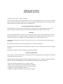
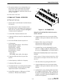
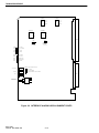
MULTI-NET SYSTEM BASIC COMPONENTS . . . . . . . . . . . . . . . . . . . . . . . . . . . . . . . . . . . . . . . . . . . . . . . . . . . . 1-2
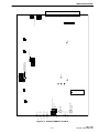
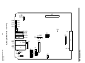
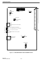
SIMULCAST SYSTEM BLOCK DIAGRAM . . . . . . . . . . . . . . . . . . . . . . . . . . . . . . . . . . . . . . . . . . . . . . . . . . . . . . 1-3
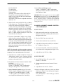
J2 CONNECTOR . . . . . . . . . . . . . . . . . . . . . . . . . . . . . . . . . . . . . . . . . . . . . . . . . . . . . . . . . . . . . . . . . . . . . . . . . . . . . 2-3
LINK TYPE . . . . . . . . . . . . . . . . . . . . . . . . . . . . . . . . . . . . . . . . . . . . . . . . . . . . . . . . . . . . . . . . . . . . . . . . . . . . . . . . . 2-6
MANUAL MAC GATES . . . . . . . . . . . . . . . . . . . . . . . . . . . . . . . . . . . . . . . . . . . . . . . . . . . . . . . . . . . . . . . . . . . . . . . 2-6
RVM ALIGNMENT POINTS . . . . . . . . . . . . . . . . . . . . . . . . . . . . . . . . . . . . . . . . . . . . . . . . . . . . . . . . . . . . . . . . . . . 2-7
MAIN PROCESSOR CARD ALIGNMENT POINTS . . . . . . . . . . . . . . . . . . . . . . . . . . . . . . . . . . . . . . . . . . . . . . . . 2-8
SMAC ALIGNMENT POINTS . . . . . . . . . . . . . . . . . . . . . . . . . . . . . . . . . . . . . . . . . . . . . . . . . . . . . . . . . . . . . . . . . . 2-9
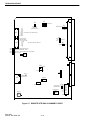
REMOTE SITE SMC ALIGNMENT POINTS . . . . . . . . . . . . . . . . . . . . . . . . . . . . . . . . . . . . . . . . . . . . . . . . . . . . . 2-10
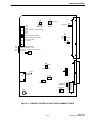
CHANNEL CONTROLLER SITE SMC ALIGNMENT POINTS . . . . . . . . . . . . . . . . . . . . . . . . . . . . . . . . . . . . . . 2-11
INTERFACE ALARM CARD ALIGNMENT POINTS . . . . . . . . . . . . . . . . . . . . . . . . . . . . . . . . . . . . . . . . . . . . . . 2-12
CIM ALIGNMENT POINTS . . . . . . . . . . . . . . . . . . . . . . . . . . . . . . . . . . . . . . . . . . . . . . . . . . . . . . . . . . . . . . . . . . . 2-13
MESSAGE BRIDGE CARD ALIGNMENT POINTS . . . . . . . . . . . . . . . . . . . . . . . . . . . . . . . . . . . . . . . . . . . . . . . 2-14
HARDWARE MENU. . . . . . . . . . . . . . . . . . . . . . . . . . . . . . . . . . . . . . . . . . . . . . . . . . . . . . . . . . . . . . . . . . . . . . . . . . B-2
HARDWARE>TOOLS . . . . . . . . . . . . . . . . . . . . . . . . . . . . . . . . . . . . . . . . . . . . . . . . . . . . . . . . . . . . . . . . . . . . . . . . B-2
HARDWARE>TOOLS>RAW TX/RX . . . . . . . . . . . . . . . . . . . . . . . . . . . . . . . . . . . . . . . . . . . . . . . . . . . . . . . . . . . . B-2
HARDWARE>TOOLS . . . . . . . . . . . . . . . . . . . . . . . . . . . . . . . . . . . . . . . . . . . . . . . . . . . . . . . . . . . . . . . . . . . . . . . . B-2
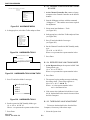
OVERLAP OFFSET CONCEPT . . . . . . . . . . . . . . . . . . . . . . . . . . . . . . . . . . . . . . . . . . . . . . . . . . . . . . . . . . . . . . . . . B-6
NO OFFSET . . . . . . . . . . . . . . . . . . . . . . . . . . . . . . . . . . . . . . . . . . . . . . . . . . . . . . . . . . . . . . . . . . . . . . . . . . . . . . . . . B-6
FIVE MICROSECOND OFFSET . . . . . . . . . . . . . . . . . . . . . . . . . . . . . . . . . . . . . . . . . . . . . . . . . . . . . . . . . . . . . . . . B-7
. . . . . . . . . . . . . . . . . . . . . . . . . . . . . . . . . . . . . . . . . . . . . . . . . . . . . . . . . . . . . . . . . . . . . . . . . . . . . . . . . . . . . . . . . . . . B-9
. . . . . . . . . . . . . . . . . . . . . . . . . . . . . . . . . . . . . . . . . . . . . . . . . . . . . . . . . . . . . . . . . . . . . . . . . . . . . . . . . . . . . . . . . . . . B-9
REMOTE SITE SMC S4 SETTINGS . . . . . . . . . . . . . . . . . . . . . . . . . . . . . . . . . . . . . . . . . . . . . . . . . . . . . . . . . . . . B-12
REPEATER CONTROLLER SMC S4 SETTINGS . . . . . . . . . . . . . . . . . . . . . . . . . . . . . . . . . . . . . . . . . . . . . . . . . B-12
REMOTE SITE SMC S3 SETTINGS . . . . . . . . . . . . . . . . . . . . . . . . . . . . . . . . . . . . . . . . . . . . . . . . . . . . . . . . . . . . B-12
REMOTE SITE SMC SWITCH S1 . . . . . . . . . . . . . . . . . . . . . . . . . . . . . . . . . . . . . . . . . . . . . . . . . . . . . . . . . . . . . . B-12
CHANNEL CONTROLLER SMC S1 . . . . . . . . . . . . . . . . . . . . . . . . . . . . . . . . . . . . . . . . . . . . . . . . . . . . . . . . . . . . B-12
LIST OF TABLES
CHANNEL ICONS DURING CALIBRATION . . . . . . . . . . . . . . . . . . . . . . . . . . . . . . . . . . . . . . . . . . . . . . . . . . . . . B-5
REPEATER ICONS DURING CALIBRATION. . . . . . . . . . . . . . . . . . . . . . . . . . . . . . . . . . . . . . . . . . . . . . . . . . . . . B-5
SMC S4 SETTINGS . . . . . . . . . . . . . . . . . . . . . . . . . . . . . . . . . . . . . . . . . . . . . . . . . . . . . . . . . . . . . . . . . . . . . . . . . . B-11
November 1998
Part No. 001-7600-001
ii
GENERAL INFORMATION
SECTION 1 GENERAL INFORMATION
1.1 SCOPE OF THE MANUAL
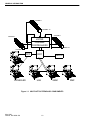
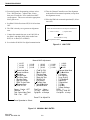
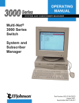
Multi-Net repeaters. The repeaters are now distributed across multiple sites. Relative to the RNT, however, Channel Controllers “appear” to be repeaters.
Review of the RNT manual, Part No. 001-3039-009,
is recommended in order to understand its operation
with respect to the UAS, SMM, RMF, CPP, Consoles,
and Telephone resources.
This manual presents an overview of the elements in an E.F. Johnson Simulcast Radio System.
The interconnections between the various elements of
the system are also illustrated. The procedures used to
tune and align the system during installation and
maintenance are then discussed.
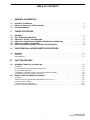
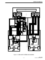
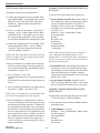
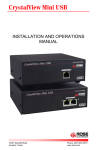
Figure 1-2 presents a more detailed view of the
remainder of the Simulcast System. To study its operation, imagine a subscriber radio making a transmission which is received by the Channel 1 Repeaters at
both the remotely located Remote Site and the centrally located Remote Site. The outputs from the
repeaters, audio on RXA± and data (Received Signal
Strength Information (RSSI) and Multi-Net data) on
VDIN, are transmitted to the RVMs associated with
Channel 1.
Before attempting to implement the procedures
discussed in this document, it is recommended that the
E.F. Johnson manuals listed below be studied.
Manual
Simulcast Application Note
Channel Controller Manual
High Stability Repeater Manual
Multi-Net® Voter Service Manual
Network Management for Simulcast:
Service Manual
Operator Manual
System Manager Manual
Part Number
009-2100-001
001-2100-200
001-2008-920
001-3039-505
For the centrally located Remote Site this is a
direct connection, while link equipment is required to
connect the remotely located Remote Site to the Central (Control) Site. The RVM uses received signal
strength information to select which signal to pass to
the Channel 1 Repeater Controller. The Repeater
Controller contains the logic processing of a normal
Multi-Net repeater, with additional signal processing
which has been developed to allow Simulcast operation, however, it has no RF hardware. The Repeater
Controller is connected to the RNT in the same manner as a Multi-Net repeater.
001-0690-201
002-0690-201
004-0690-203
1.2 WHAT IS A SIMULCAST RADIO SYSTEM?
Simulcast as it applies to an E.F. Johnson twoway radio system is the simultaneous transmitting of a
message from two or more radio sites on the same
radio channel. In addition, the strength of the receive
signal at the various sites is monitored and a “Voter”
selects the strongest signal. That signal is then routed
to all the sites for retransmission.
The audio and Multi-Net data from the Repeater
Controller, which is to be transmitted over the air, is
passed to splitters. The outputs from the splitter are
available for direct connection to the centrally located
Remote Site and for linking to remotely located
Remote Sites. The audio/data signal is connected to
MA/MB on the repeaters, is processed, and is then
transmitted over the air.
1.3 SYSTEM ELEMENTS
An E.F. Johnson Simulcast Radio System will
typically incorporate a Network Management System. Section 2 of “Network Management for Simulcast: Service Manual” provides a review of the elements of the Network Management System. The
discussion in this manual will, therefore, focus on the
other Simulcast System components.
Additional Simulcast related equipment is shown
in Figure 1-2. The GPS units, 10 MHz splitter drawer,
and OCXO drawer are required to maintain synchronization throughout the entire system. Also shown in
Figure 1-2 is standard equipment such as combiners,
duplexers, and multiplexers.
Figure 1-1 shows a high level view of the basic
components of a Multi-Net System, with the exception that Channel Controllers now take the place of
1-1
May 1998
Part No. 004-0690-303
GENERAL INFORMATION
CHANNEL 1
CHANNEL 10
CHANNEL 1
CHANNEL 1
VOTER
CHANNEL
CONTROLLERS
CHANNEL 10
CHANNEL 10
CPP
CONSOLES
RNT
UAS
TELCO
SMM
Figure 1-1 MULTI-NET SYSTEM BASIC COMPONENTS
May 1998
Part No. 004-0690-303
1-2
RMF
1-3
RECEIVE
MULTIPLEXER
DUPLEXER
TRANSMIT
COMBINER
REMOTE SITE (S2)
REMOTELY LOCATED
REMOTE SITE (S1)
PS
GPS
10 MHz
1 PPS
10 MHz
GPS
10 MHz
SPLITTER
DRAWER
10 MHz
CENTRALLY LOCATED
RECEIVE
MULTIPLEXER
DUPLEXER
TRANSMIT
COMBINER
10 MHz
PS
1.25MHz
CHANNEL 2
REPEATER
RX
RXA-
RXA+
MB
MA
GND
VDIN
HI STAB
SMC
SYNC
1.25MHz
REPEATER
CHANNEL 2
TX
GND
VDIN
RXA-
RXA+
MB
MA
RXA-
RXA+
MB
MA
GND
VDIN
SMC
SYNC
HI STAB
REPEATER
CHANNEL 1
RX
TX
RX
TX
GND
VDIN
RXA-
HI STAB
SYNC+
SMC
OCXO DRAWER
1 PPS
10 MHz
10 MHz
PS
MB
MA
RXA+
SYNC+
SMC
HI STAB
REPEATER
CHANNEL 1
OCXO DRAWER
10 MHz
RX
TX
VOTER
SHELF
POWER
SUPPLY
RNT/SMM
VDM
CIM 1
CIM 2
1 PPS
PS
REPEATER
CONTROLLER
2
RVM
CH 2
DATA IN AUDIO IN
CH 2
SPLITTER
CHANNEL CONTROLLER
REPEATER
CONTROLLER
1
CH 1
CENTRAL SITE
10 MHz
VOTER SHELF
AUDIO IN
RVM
DATA IN
CH 1
SPLITTER
VF-5A
MA-301
(2 OF 2)
CH 2
CH 1
VF-5A
MA-301
(2 OF 2)
CB 3 DA-191A
MA-404
(2 OF 4)
LINK EQUIPMENT
CH 1
CH 2
CB 3 DA-191A
MA-404
(2 OF 4)
DIGITAL
LINK
GENERAL INFORMATION
Figure 1-2 SIMULCAST SYSTEM BLOCK DIAGRAM
May 1998
Part No. 004-0690-303
GENERAL INFORMATION
May 1998
Part No. 004-0690-303
1-4
TUNING PROCEDURE
SECTION 2 TUNING PROCEDURE
2.1 GENERAL
2. With Network Management, set the Channel controller SMC Audio and Data Gain to 1.0000 (click
on the System icon and pull down:
System -> Calibration -> SMC Configuration
and the configuration window pops up).
This section presents the procedures used for
adjusting signal levels through the Simulcast System.
It is intended for use during system installation and for
periodic maintenance. It will be helpful to refer to figures 1-1 and 1-2 when implementing the procedures.
3. With Network Management, set all Remote Site
SMC Audio Gains only to 1.0000 (see Step 2).
NOTE: Whenever a Remote Site repeater is powered
off, then on during the course of this tuning procedure,
no activity (i.e. a Multi-Net call) should be present
while the repeater powering steps are occurring. This
and waiting 1-2 minutes after powering the Remote Site
repeater on allows the RVM in the Voter to self-align/
stabilize.
4. On the Channel Controller, place the SMC on an
extender card (may need 10 MHz extender cables).
NOTE: See Appendix A for the procedure to properly
remove and re-insert Channel Controller cards ("hot
swapping") in an operating system, if necessary.
5. On the Remote Site, place the SMC on an extender
card (may need 10 MHz extender cables).
2.2 TEST EQUIPMENT REQUIRED
•
•
•
•
•
•
6. On the Channel Controller, switch the SMC
switch S4, section 5 "On" (this sends a 1 kHz tone
to the Remote Sites).
IFR-1200 or equivalent, 2-each
Oscilloscope
Transmission Test Set, 2-each
Signal/Encoder/Decoder Box (SED)
Appropriate Cables/Connectors
Version 8.4 Repeater Programming Software
CHANNEL CONTROLLER TRANSMIT LEVEL
ADJUST
2.3 SIMULCAST TUNING - TRANSMITTERS
7. On the back of the Channel Controller, connect a
transmission test set to TxMOD± and adjust R29 on
the SMC for -12.0 dBm at 1 kHz. (Ensure that the
test set is receiving in Bridge mode and not
Terminate mode.)
SETTING UP
1. Place the Channel Under Test on the Channel Controller (CC) and all Remote Sites (RS) into "Set-Up
State". The Channel Under Test needs to remain in
Set Up State for the duration of the tuning procedure. Use either Network Management (click on
each individual icon and pull down: Repeater ->
Set-Up State) or switch SMC switch S4, section 2
"On" for each component (see Figure 2-7).
8. Connect the test set to the 1:6 splitter outputs to
check for unity gain. (If outputs are not -12.0 dBm,
adjust the splitter’s front panel gain control for
-12.0 dBm).
REMOTE SITE REPEATER TRANSMIT AUDIO
LEVEL ADJUST
NOTE: Plan ahead, as using Network Management
for Set-Up State needs to be reset whenever a component is restarted and using the hardware switch
for Set-Up State needs to be physically reset for
Normal State at some point.
9. On the back of the Remote Site Repeater, connect
the test set to MA/MB and verify a -12 dBm,
±0.2 dBm at 1 kHz reading. (If outputs are not
-12 dBm, check the link equipment and connections for settings and accuracy).
2-1
May 1998
Part No. 004-0690-303
TUNING PROCEDURE
NOTE: A condensed version of the steps necessary is
listed here. For more detailed description of the operation or for troubleshooting information, refer to the
Network Management For Simulcast Service Manual
(Part No. 001-0690-201) Section 7 Alignment and Calibration.
10.On the Remote Site Repeater, connect an oscilloscope to SMC WO-10 and adjust R37 for 1.9V P-P
(-1.2 dBm at 1 kHz with a test set).
11. At the Remote Site SMC, use a receiving IFR to
adjust R32 for 1.5 kHz deviation (1.2 kHz for
NPSPAC).
2. At the Network Manager, click on the System
icon and pull down:
System -> Calibration -> Threshold Alignment.
A window titled "Threshold Alignment" should pop
up.
REMOTE SITE REPEATER TRANSMIT DATA
LEVEL ADJUST
12.At the Channel Controller, turn SMC switch S4,
section 5 "Off" (1 kHz tone), and turn SMC switch
S4, Section 4 "On" (125 Hz Tone).
3. Click on the channel you just completed tuning at
all Remote Sites to highlight both the channel and
the "Start Alignment" box.
13.At the Remote Site, use a receiving IFR to monitor
deviation. With Network Management, adjust the
appropriate Remote Site SMC Data Gain (see Step
2 for location of the pop up memu) for precisely 1.0
kHz deviation.
4. Click on the Start Alignment box. Operation of the
Host computer should take about 1-2 minutes to run
for a 3 Site channel. If it has successfully finished
running, a "C" will be listed next to the channel and
an "OK" will be listed next to each Remote Site portion of this channel. The numbers that have been
calculated have already been written to each component of this channel. Troubleshooting should be
done on the repeater that did not have an "OK" after
Threshold Alignment is complete.
NOTE: Adjust the Data Gain of the Remote Site
Repeater which is being aligned. DO NOT adjust
the Channel Controller Data Gain.
14.At the Channel Controller, turn SMC switch S4,
section 4 "Off".
5. Click on the "Close" box.
15.This concludes the Simulcast portion of the tuning
procedure for this channel at this Remote Site. At
the Remote Site, remove the SMC from the
extender card and replace the SMC in the repeater.
NOTE: A uni-directional system is assumed.
6. At the Network Manager, click on the System icon
and pull down:
System -> Calibration -> Manual Calibration.
A window titled "Manual Calibration" should pop
up.
IMPORTANT
Section 2.3, Steps 5-6 and 9-15 must be repeated for all
Remote Site repeaters for this channel before continuing with Section 2.4.
7. Click on the channel that you have just completed
the successful Threshold Alignment on to highlight
the channel.
NOTE: This tunes the Simulcast transmitter portion of
the channel from a single point, the tones from the
Channel Controller SMC.
8. Click on the "Acquire Data" box. Operation of the
Host computer should take under 1 minute to run for
a 3 Site channel. If it has successfully finished running, a "W" will be listed next to the channel and an
"OK" will be listed next to each Remote Site portion
of this channel. Troubleshooting should be done on
the repeater that did not have an "OK" after Manual
Calibration is complete.
2.4 SIMULCAST THRESHOLD ALIGNMENT
AND MANUAL CALIBRATION
1. When completed with the Simulcast tuning portion
of a specific channel, threshold alignment and manual calibration is next to be performed with Network Management.
May 1998
Part No. 004-0690-303
2-2
TUNING PROCEDURE
9. The numbers that have been calculated have not
been written to each component of this channel.
Click on the "Write" box. Do not click on the
"Write" box, if Manual Calibration did not successfully get completed.
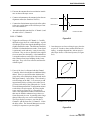
RXA+
RXA-
10.Click on the "Close" box.
1
2
2.5 SIMULCAST TUNING - RECEIVERS
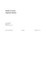
33
SETTING UP THE CALL
J2
1. Place the MAC on the Extender Card in the Remote
Site repeater.
34
2. Turn on the repeater. (Wait 1-2 minutes for the
RVM in the Voter to self-align before bringing up a
Multi-Net call, especially if alignment through the
voter has not been completed.)
Figure 2-1 J2 CONNECTOR
REMOTE SITE REPEATER RECEIVE AUDIO
LEVEL ADJUST
3. Set the IFR to Transmit a Multi-Net call.
a. Connect the SED box to the Ext. Mod SINAD Port
of the IFR.
4. Connect transmission test set between the RXA+
and RXA- on the green connector on the rear of the
repeater.
b. Power the SED Box from the repeater IAC.
5. Ensure a call is set up: (see Figure 2-9)
CR540 on IAC (Mobile-Green LED)
CR500 on IAC (Transmit-Red LED).
c. Set Parameters:
Display Entry/Encode Date = Encode Data
Repeater/Mobile = Mobile
Digital/Analog = Analog
Normal/Inverted = Normal
Encode/Decode = Encode
Enter the data as:
System Key
UID HOME GID GOTO STA PRI R
6. Set Audio Tone Level by adjusting R239 on the
MAC for -12 dBm at 1 kHz tone. (Remember to set
the test set for Bridge Mode, not Terminate Mode.)
REMOTE SITE REPEATER PILOT TONE LEVEL
ADJUST
d. Connect the IFR to the Receive port of the
repeater.
NOTE: Section 2.5, Steps 4-6 must be done first. R239
sets the Main Level Output. The Pilot Tone rides with
this level.
e. Set the frequency to the Receive frequency.
7. Take the call down by placing the IFR to RCV.
f. Position the IFR to generate.
8. Connect transmission test set between the RXA+
and RXA- on the green connector on the rear of the
repeater.
g. Check that the Data Level coming from the SED is
at 1 kHz Deviation. (If the level is low or high,
Adjust Data out POT on the SED Box.)
9. Set Pilot Tone Level by adjusting R240 on the MAC
for -20 dBm at 1200 Hz tone. (Wait 1-2 minutes for
the RVM to self-align/stabilize when adjustment is
complete, especially if alignment through the voter
has not been completed.)
h. Set the IFR to generate a 1 kHz tone at 1.5 kHz
deviation (1.2 kHz deviation NPSPAC).
2-3
May 1998
Part No. 004-0690-303
TUNING PROCEDURE
VOTER (RVM) AUDIO LEVEL ADJUST
CHANNEL CONTROLLER RECEIVE DATA LEVEL ADJUST
10.Bring the call back up at the Remote Site.
16.Set up a call with no audio at the Remote Site.
11. Connect the Transmission Test Set to RVM audio
input (RDM+/RDM-) on the punch block or on the
Backplane of the Voter shelf for the appropriate
Remote site. (Between Remote Repeater and
associated RVM.)
17.At the Channel Controller Site, with the SMC in
the extender card, connect an oscilloscope to P100,
pin 29 (Tx MOD) and ground. The data level
should be 0.8V P-P. If not, start “2000pgmr -e”,
then adjust U151 with the following gates ON.
(see Figure 2-3).
Hardware > Tools > Manual MAC Adjust
Voter Audio Mute
Rx Mute
Rx Option Gate
Repeat Gate
Tx Option Gate
Normal Mod Mute
Tx Mod Mute
12.Verify a -12 dBm at 1 kHz signal. (If the value is
incorrect, verify a -12 dBm signal at RXA+/RXAat the Remote Site. If the signal is present, check
the wiring and link equipment.) This step checks
for loss between Remote Site and input to the Voter.
13.Connect the Transmission Test Set to RVM voted
audio output (MLM Audio +/-) to the Channel
Controller. This is the connection between the
Voter and Channel Controller.
NOTE: Must exit the Test Screen to view adjusted
result. When the manual MAC adjust screen is
displayed there is no data output. ESC (escape) from
this test screen to view the data. The correct levels are
obtained by trial and error.
NOTE: If the Voter output has not been tuned, proceed
with Step 14 only. If the Voter output has been tuned,
proceed with Step 15 only.
14.The level should be at -12 dBm with a 1 kHz tone.
If incorrect and no tuning of the Voter output has
been completed, the RVM output EEPOT needs to
be adjusted (see Figure 2-4).
18.At the Remote Site, with the Data Only Multi-Net
call still up, set up a receiving IFR with the appropriate frequency and the antenna port connected to
either the monitor port of a transmit combiner.
Using a rubber duck antenna may result in receiving
adjacent site’s signal.
a. Set S2, sections 1, 3 Off; 2 On.
(Set section 4 Off to increase the output when pressing S1).
(Set section 4 On to decrease the output when pressing S1).
19.At the Channel Controller, adjust R37 on the
SMC for a data deviation of 1.0 kHz, ±15 Hz, using
the receiving IFR at the Remote Site, if necessary.
b. Press S1 (bottom push button) in to change the output value to -12 dBm , ±0.5 dB at 1 kHz.
CHANNEL CONTROLLER RECEIVE AUDIO
LEVEL ADJUST
NOTE: Step 15 is included only to verify that the channel’s Voter output alignment was done properly.
20.Add audio to the Data Only Multi-Net call, still at
1.5 kHz deviation (1.2 kHz for NPSPAC).
15.The level should be at -12 dBm with a 1 kHz tone.
If incorrect and tuning of the Voter output has been
done, bring the call down and wait 1-2 minutes for
the Voter input for this Remote Site to self-align to
the Pilot Tone. Bring the call back up and recheck
the level. Record the level if it is still incorrect (one
that is outside of ±0.5 dB of -12 dBm). Do this for
the remaining Sites for this channel to determine if
there was a problem when the Voter output level
was set or if there is a variance in this Site’s Voter
output on this RVM.
May 1998
Part No. 004-0690-303
21.This step checks the level of the Channel Controller
audio input stage.
a. Using 2000pgmr -e, go into:
Hardware -> Tools -> Manual MAC Adjust. Select
the following gates:
Voter Audio Mute
Rx Mute
Rx Option Gate
Repeat Gate
2-4
TUNING PROCEDURE
24.At the Network Manager, under
System -> Calibration -> SMC Configuration,
change the Channel Controller’s SMC Data Gain
from 0.0000 to 1.0000.
LEVEL DETECT
Tx Option Gate
Normal Mod Mute
Tx Mode Mute
(Selecting ’Level Detect’ allows J100 and J103Ground to be monitoring points for the call’s
audio level at a point after the Voter Audio Input
Adjust stage [R233].)
Also select ’U149’ (not to be adjusted at this time)
and Select ’F2’.
IMPORTANT: Performing Section 2.5, will tune ONE
Remote Site’s Repeater Receive and the channel’s Voter Audio and the Channel Controller Audio and Data
levels. Section 2.5, Steps 1-15 need to be performed at
the remaining Remote Sites for completion of Simulcast
Tuning-Receivers.
b. With a Test Set, measure J100/J103 for -6.0 dBm at
1 kHz (factory set). The full range of R233 would
yield levels at this test point from -14 dBm to
+3 dBm. The range of the EEPOT U149 (which is
adjusted, if necessary, in Steps 22-23) will NOT
reach the appropriate output level if this test point is
below -8.5 dBm. If the level is not -6.0 dBm but
above -7.5 dBm, continue with Step 22. If not, continue with the rest of Step 21.
2.6 AUDIO ALIGNMENT CHANNEL CONTROLLER TO/FROM RNT
AUDIO TO RNT
1. Make sure that a Remote Site is still setup with a
Multi-Net call, with Audio/Data (Do Not start the
2000pgmr at this time).
c. Escape the ’Manual MAC Adjust’ screen. Bring
down the call by placing the IFR into RCV. The
SMAC will need to be placed on the extender card.
From Step 19, the SMC should be on the extender
card. Turn the Channel Controller shelf off. Swap
the 2 cards and turn the shelf back on. Bring the
Multi-Net call with audio (same deviation) back up.
Repeat Step 21a here.
2. Place the SMAC into an extender card.
3. Connect the transmission test set to SRXA±.
4. Adjust R239 (Main Audio to RNT) on the SMAC
for -12 dBm (see Figure 2-6).
5. On the associated CIM, connect the transmission
test set between J11 and ground (see Figure 2-10).
NOTE: See Appendix A for the procedure to properly
remove and re-insert Channel Controller cards ("hot
swapping") in an operating system, if necessary.
6. Adjust R41 on the CIM for -6 dBm.
d. Adjust R233 for -6.0 dBm at J100/J103. Escape the
’Manual MAC Adjust’ screen. Continue with Step
22. (For Section 2.5, Steps 22-24, the SMAC can
remain on the extender card.)
AUDIO FROM RNT
7. Set the CIM into Test 1 (S5, section 1 Off;
sections 2, 3 and 4 On).
22.Shut the data off in the Channel Controller’s SMC
as follows:
In the Network Manager under:
System -> Calibration -> SMC Configuration
change the data gain from 1.0000 to 0.0000.
8. Connect transmission test set between J12 and
ground.
9. Adjust R44 on the CIM for -12 dBm.
23.At the Channel Controller, adjust U149 on the
SMAC using the 2000pgmr with the same gates on
as in Step 2 for an audio deviation of 1.5 kHz,
±15 Hz (1.2 kHz, ±15 Hz NPSPAC) using the
receiving IFR at the Remote Site, if necessary.
10.Start the 2000pgmr at this time. Make sure that the
Link Type is Digital. From the Repeater Programming software select:
Test > RNT Interface > Select Link Type > RS232
(see Figure 2-2).
2-5
May 1998
Part No. 004-0690-303
TUNING PROCEDURE
12.Take the Channel Controller out of the alignment
mode and back into normal operation (escape from
the alignment screen).
11. From the Repeater Programming software select:
Test > RNT Interface > Adjust Links <Enter>
then press F2 until the “Voice Audio from RNT”
screen appears. This screen selects the appropriate
MAC gates to on.
13.Place the CIM back to normal operation (S5, all sections Off).
a. Set SMAC S100 all sections OFF, S101 all sections
OFF.
Repeater Data Path Selection
Select the Data Path between the Repeater and the RNT.
b. The CIM is already set to generate an alignment
tone.
( ) Data over Voice
( ) Separate Data
( ) RS232
c. Connect the transmission test set to J100/J103 on
the SMAC and adjust R243 (Main Audio from
RNT) for -6 dBm (387 mV RMS).
Press ENTER to Accept
Press Spacebar to Select
d. Set switches S100/S101 for digital communication.
Figure 2-2 LINK TYPE
Manual MAC Adjustment
( ) U137
( ) U138
( ) U139
(
(
(
(
(
(
(
(
(
(
( ) U140
( ) U141
( ) U142
) Voter Aud Mute
) Local Aud Mute
) Rx Mute
) Rx Opt Gate
) Rx Voice Gate
) Rx Aud Gate
) Rx Voice to Bp
) FSK To Aud Gate
) Repeat Gate
) TxS To FSK
Space - Carrier: OFF
Channel: 0
Tab - Select Next Field
FN4 - Fan: OFF
(
(
(
(
(
(
(
(
(
(
( ) U143
( ) U144
( ) U145
( ) U146
( ) U147
( ) U148
) TxA To FSK
) Data To A/D
) Tx Aud Gate
) Tx Voice Gate
) Data Lvl Test
) CWID Cntl
) Lvl Detect
) Tx Opt Gate
) Local Mic Mute
) Ext Mod Mute
Test Freq: None
Tx Freq: 2489.387
PgUp/Dn: ±10 steps
Press F2 to Adjust Pot
Press Spacebar to Select
Figure 2-3 MANUAL MAC GATES
May 1998
Part No. 004-0690-303
2-6
( ) U149
( ) U150
( ) U151
( ) Normal Mod Mute
( ) Tx Mod Mute
( ) Tx Intcom
( ) Rx Sq Actv
( ) Log Sq A/D
( ) Tx Mod A/D
( ) Norm Rx
( ) Digital Mod
( ) Tx Net
( ) Rx Net
( ) Clear Settings
RSSI: 0
Rx Freq: 2444.387
CurUp/Dn: ±1 step
2-7
CR11
CR12
CALL GRN
S1
CR10
YEL
ON
EEPOT SELECT (CS1 - CS6)
DOWN
UP
PULSE EEPOT
AUDIO LEVEL
ADJUST
S8 RESET
YEL
1
2
3
4
S2
CR8
CR9
YEL
CR6
CR7
GRN
CR5
YEL
CR4
GRN
CR3
YEL
GRN
+5V GRN
SITE 4
SITE 3
SITE 2
CR2
CR1
YEL
GRN
14
8
1
U27
15
28
TP2
TP3
TP5
TP1
BIT 9
BIT 8
cRVM ADDRESS (1-30)
TP4
RVM
cRVM
S3
ON
8 7 6 5 4 3 2 1
OFF - 2400 BAUD LINK TO NORMAL MLM
ON - 9600 BAUD LINK TO REMOTE MLM
ON
RVM ADDRESS (1-7)
TP6
J4
1 2
J6
1 2
S6
11
1
J5
BIT 7
BIT 6
BIT 5
BIT 4
4
3
2
1
4
3
2
1
64 32
33 1
S7
GO TO FCC CHANNEL NUMBER
BIT 3
BIT 2
BIT 1
BIT 0
ON
SITE 1
2
J3
1
2
J2
1
S5
8 7 6 5 4 3 2 1
P1
TUNING PROCEDURE
ON
Figure 2-4 RVM ALIGNMENT POINTS
May 1998
Part No. 004-0690-303
TUNING PROCEDURE
S3
ON
S2
ON
33
12 3 4 12 3 45 67 8
BALANCED RX/TX
RESET
S1
1
WATCHDOG
J6
12 3
J5
1 2 3 HSDB
11.059 12
MULTI-NET
24 6
1 3 5
1
P1
J4
EPROM MEMORY
LOADING
10
DS1
USED WITH CR3/4 FOR ALARMS
5
6
CR1
GRN - MPC OPERATIONAL (BLINKING)
CR2
YEL - ON = HIGH POWER, OFF = LOW POWER
CR5
YEL - ON = LTR, OFF = MULTI-NET
CR4
RED
CR3
RED
64
USED WITH DS1 FOR ALARMS
+5V
7A 1
2
J1
J2
PROGRAMMING
CONNECTOR
3 21
+12V
MEMORY
SELECT
6
8B
COMPUTER I/O
1 2
J3
76800
38400
19200
9600
4800
2400
1200
13 14
Figure 2-5 MAIN PROCESSOR CARD ALIGNMENT POINTS
May 1998
Part No. 004-0690-303
2-8
32
TUNING PROCEDURE
3
J105
WATCH DOG
NORMAL
2
1
S101
ON
4
3
RNT RS-232
2
1
P101
S102
SEC AUDIO
TO RNT
U149
TX
RX NET
5
4
3
2
1
SPEAKER
3 TXS+
4 TXS-
2
1
VOTER AUDIO 25
NOISE
LEVEL
P100
RX WB AUDIO 27
13 MAIN AUDIO TO RNT
VOTER
AUDIO
LEVEL
RX VOICE
LEVEL
TX VOICE
LEVEL
R305 R233
RX VOICE 31
TX VOICE 32
R237
J101
J104
3
RX DATA
LEVEL
J102
R235
SPEAKER/MIC
1
4
RX AUDIO
ADJUST
R234
LOCAL MIC
17
5
MAIN AUDIO
FROM RNT
R236
ON/OFF/VOL
6
R238
LOCAL SPKR
7
R243
U151
ON
8
MAIN AUDIO
TO RNT
R100
TX
DATA
LEVEL
SECONDARY AUDIO
TO RNT
S100
R239
EXTERNAL MODEM
2-3/4-5 NORMAL OPERATION
1-2/3-4 LTR DATA MODEM
FSK
TO RNT
SEC AUDIO
FROM RNT
15 TX AUDIO +
16 TX AUDIO -
TX
VOICE
LEVEL
R244
TEST POINT
J100
R301
MOD
LEVEL
A D LEVEL
R242 R241
J103
R240
GND
Figure 2-6 SMAC ALIGNMENT POINTS
2-9
May 1998
Part No. 004-0690-303
TUNING PROCEDURE
J5
J9
1200
9600
19200
2 1
5 3 1 BAUD RATE
6 4 2
LAST SMC
SPLITTER
TERMINATION
1
8us
2
16us
3
32us
4
64us
5 125us FINE DELAY/COURSE DELAY
6 250us
7 500us
8 1000us
J6
1 MW ON/OFF
2 SETUP STATE
3 N/A LEAVE OFF
4
11.25
5
22.5
TX LEVEL/PHASE ADJUST
6
45
7
90
8
180
S4
CR8
CR9
CR10
CR11
DISABLE
GND
TX
RX
1 2 3
S3
J3
WATCHDOG 3 2 1
DSP DATA
J8
2 1
VOTER DATA IN
RED (NOT USED/ALWAYS ON)
GREEN (ON=REMOTE SITE)
YELLOW (1 PPS/10 MHz WHEN FLASHING)
RED (ON=TX)
J56
10 MHz IN
J52
1 2 3 4 5 6
1 2 EPROM
3 4
5 6
BOOT-UP MODE
WO 10
J57
COMPUTER
CONNECTOR
TX MOD
R32
R37
BALANCED
MA/MB INPUT
AUDIO/DATA
OUT
RESET
R29
S2
1 2
J7 RS1
AUDIO/DATA IN
RS2
RS3
RS4
CC3
CC2
CC1
CC4
SIGNAL PATH
Figure 2-7 REMOTE SITE SMC ALIGNMENT POINTS
May 1998
Part No. 004-0690-303
1 ON
2 ON
3 ON
4 OFF
5 ON
6 OFF
7 OFF
8 OFF
2-10
TUNING PROCEDURE
J5
J9
1200
9600
19200
21
5 3 1 BAUD RATE
6 4 2
LAST SMC
SPLITTER
TERMINATION
8us
1
2 16us
32us
3
4 64us
5 125us FINE DELAY/COURSE DELAY
6 250us
7 500us
81000us
1
2
3
4
5
6
7
8
S4
STOP/PASS DATA SIGNALING
ENABLE/DISABLE SETUP STATE
DISABLE
GND
TX
RX
125 Hz DATA TONE
1 kHz TONE
J6
DSP DATA
J8
21
VOTER DATA IN
(OPEN)
RED (NOT USED/ALWAYS ON)
GREEN (ON=REMOTE SITE)
YELLOW (1 PPS/10 MHz WHEN FLASHING)
RED (ON=TX)
J56
10 MHz IN
J52
1 2 EPROM
3 4
5 6
BOOT-UP MODE
1 2 3 4 5 6
WO 10
J57
COMPUTER
CONNECTOR
TX MOD
R32
R37
J7RS11 OFF
AUDIO/DATA IN
BALANCED
MA/MB INPUT
AUDIO/DATA
OUT
RESET
R29
S2
1 2
CR8
CR9
CR10
CR11
(OPEN)
1 2 3
S3
J3
WATCHDOG 3 2 1
RS2 2 OFF
RS3 3 OFF
RS4 4 OFF
CC3 5 OFF
CC2 6 ON
CC1 7 ON
CC4 8 ON
SIGNAL PATH
Figure 2-8 CHANNEL CONTROLLER SITE SMC ALIGNMENT POINTS
2-11
May 1998
Part No. 004-0690-303
TUNING PROCEDURE
ALARM 1
1
8
2
S500
ALARM 3
8
S502
5
2
GND
1
8
S503
3
4
GND
1
S501
5
2
+5V
+15V
33 1
3
4
GND
ALARM 4
+5V
+15V
1
8
3
4
5
ALARM 2
+5V
+15V
5
2
+5V
+15V
3
4
GND
P500
J504
J503
1
2
3
ALARM 3
OUTPUT
1-2 ALARM
2-3 AD LEVEL
CR525
+15V (GRN)
CR523
+15V ACC (GRN)
CR524
-5V (GRN)
CR501
+5V (GRN)
CR503
CWID (GRN)
CR502
HANG (YEL)
CR505
SWITCH (YEL)
CR504
MOBILE (GRN)
CR500
XMIT(RED)
1
2
3
ALARM 4
OUTPUT
1-2 ALARM
2-3 AD LEVEL
64 32
17
J500
GROUND
J501
+15V TP
J502
POWER SUPPLY
DC ON/OFF
4 3 2 1
AD LEVEL TP
1
J505 SQUELCH ENABLE OUTPUT
- INVERTED
- NON-INVERTING
- NON-INVERTING (U503 CONTROL)
P501
S508
32
Figure 2-9 INTERFACE ALARM CARD ALIGNMENT POINTS
May 1998
Part No. 004-0690-303
2-12
16
S2
J31
11 10 9 8 7 6 5 4 3 2 1
J24
3
2
1
CR401
(YEL)
CR403
(RED)
CR402
(GRN)
CR404
DS1
TP5
GROUND
MAIN TX
MAIN RX
MAIN RX
R44
MAIN TX
33 1
S5
ON
J13
J12
J11
R41
4
3
2
1
2-13
Figure 2-10 CIM ALIGNMENT POINTS
(GRN)
TP3
MAIN OUTPUT (Tx)
J2
6
5
4
3
2
1
P33
R102
TP9
J15 2 1
2 1
J14 R90
TP4
S3
4
3
2
1
ON
4
3
2
1
ON
S4
J27
3
2
1
11
10
9
8
7
6
5
4
3
2
1
64 32
4
S1 32
1
ON
P1
J36
1
2
3
TUNING PROCEDURE
May 1998
Part No. 004-0690-303
TP8
1
2
3
4
5
6
7
8
J32
MON/ MAIN INPUT (Rx) J22
LINE
J1 (LINE) 12 12 J21
EQU
MON/
LINE
EQU
P2
R83 R86
TUNING PROCEDURE
S3
ON
S2
ON
33
12 3 4 12 3 45 67 8
BALANCED RX/TX
RESET
S1
1
WATCHDOG
J6
12 3
J5
1 2 3 HSDB
11.059 12
MULTI-NET
24 6
1 3 5
1
P1
J4
EPROM MEMORY
LOADING
10
DS1
USED WITH CR3/4 FOR ALARMS
5
6
CR1
GRN - MPC OPERATIONAL (BLINKING)
CR2
YEL - ON = HIGH POWER, OFF = LOW POWER
CR5
YEL - ON = LTR, OFF = MULTI-NET
CR4
RED
CR3
RED
64
USED WITH DS1 FOR ALARMS
+5V
7A 1
2
J1
J2
PROGRAMMING
CONNECTOR
3 2 1
+12V
MEMORY
SELECT
6
8B
COMPUTER I/O
1 2
J3
76800
38400
19200
9600
4800
2400
1200
13 14
Figure 2-11 MESSAGE BRIDGE CARD ALIGNMENT POINTS
May 1998
Part No. 004-0690-303
2-14
32
CARD REMOVAL AND RE-INSERTION PROCEDURE
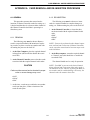
APPENDIX A CARD REMOVAL AND RE-INSERTION PROCEDURE
A.1 GENERAL
A.1.2 RE-INSERTION
This procedure assumes that removal and reinsertion of Channel Controller cards (for testing, etc.)
is desired and that there is at least one other channel in
this Channel Controller shelf that is operating in a
Simulcast system.
The following steps must be taken to re-insert
cards in a required channel to complete changes or
tuning, etc. without turning the power to the shelf off.
1. At the Channel Controller, re-insert the three
cards associated with the required channel in this
order:
•SMC
•SMAC
•MPC
A.1.1 REMOVAL
The following steps must be taken to Remove
cards in a required channel with intentions of replacing a card or to place a card in an extender card without turning the power to the shelf off.
NOTE: If tests to be performed on this channel require
more removal and re-insertion of Channel Controller
cards, repeat the removal and re-insertion steps in the
order listed here.
1. At the Host Computer, place the required channel
in Setup State (this should also disable the associated CIM).
2. At the Host computer, return the required channel
to "Normal" state (this should also re-enable the
associated CIM).
2. At the Channel Controller, remove the three cards
associated with the required channel in this order:
The channel should now be ready for operation.
NOTE: If an MBC is present in the desired channel
during removal and re-insertion of the other cards, it
can remain in its slot. Likewise, if placing the MBC on
an extender card for troubleshooting is necessary, the
channel cards can remain in their slots.
CAUTION
Cards must be removed and re-inserted in proper
order or severe damage may occur.
•MPC
•SMAC
•SMC
3. At this time, a card can get switched or an extender
can be put into place, so that re-insertion of the
cards can take place.
A-1
May 1998
Part No. 004-0690-303
CARD REMOVAL AND RE-INSERTION PROCEDURE
May 1998
Part No. 004-0690-303
A-2
PAST PROCEDURES
APPENDIX B PAST PROCEDURES
B.1 ALIGNMENT AND AUTO CALIBRATION
3. Put Channel Controller in SMC Standby mode.
B.1.1 GENERAL
4. Put repeaters in SMC Link Timing mode. Ensure
that the returned value is 0 (zero). Adjust Threshold
as required.
This section describes use of the Network Management system for performing the time and phase
alignment of an E.F. Johnson Simulcast Radio System.
Simulcast systems must be aligned and calibrated to
avoid distorted signals in areas that have repeater coverage overlap. During calibration the Channel Controller sends a timing tone that is used to determine the
length of time it takes for a signal to reach each
repeater. The repeaters’ buffer and phase delays are
then adjusted so that all repeaters will transmit at the
same time and phase. The timing of the entire system
is synchronized by Global Positioning System (GPS).
5. Put the Channel Controller in SMC Link Timing
mode. Ensure that the repeater is returning on-zero
values. Adjust Timing Tone Gain as required.
6. Put the repeater in SMC Normal mode.
7. Put the Channel Controller in SMC Normal mode.
8. Put all repeaters on the channel in Normal State.
B.1.3 DETAILED PROCEDURE
B.1.2 ALIGN THRESHOLD AND TIMING TONE
GAIN
The following steps must be repeated for every
channel in the system, and for every repeater (at all
sites) in the system. One person is needed at the site
containing repeaters, one person at the site containing
the Channel Controllers, and one person to operate the
Host Computer. If equipment is collocated, this may
be accomplished with two people.
Before the Network Management System can
calibrate a Simulcast System, the repeaters and Channel Controllers must be adjusted properly. This procedure sets the appropriate parameters to ensure calibration by the Network Manager.
B.1.2.1 EQUIPMENT REQUIRED
•
•
Network Management host computer running
OpenView. (If the System -> Calibration -> SMC
Configuration menu is not present, exit OpenView,
copy the file SERVICE.INI from the first installation disk to the \SITECTR directory, then restart
OpenView.)
B.1.3.1 REPEATER SETUP STATE
•
Click on a repeater icon.
Two laptop computers with 2000pgmr software
(version 8.38 beta or later) and repeater programming cables.
•
Select menu item Repeater > Setup State.
•
Repeat for each repeater at each site in the system.
From the Host Computer put all repeaters in the
system in Setup State.
B.1.2.2 OVERVIEW
B.1.3.2 REPEATER SMC STANDBY MODE
The process of setting up a Simulcast System to
allow Network Management calibration involves the
following steps, which are detailed in Section B.1.3.
1. At the Repeater Site connect a laptop computer to
the repeater on the desired channel.
2. Start the 2000pgmr software with the command
“2000pgmr -e”. This enables menu items required
for adjustment.
1. Put all repeaters in Setup State.
2. Put repeaters in SMC Standby mode.
3. Select menu item Hardware > Tools.
B-1
May 1998
Part No. 004-0690-303
PAST PROCEDURES
B.1.3.3 CHANNEL CONTROLLER SMC STANDBY MODE
File Edit Transfer Hardware Test Utilities
HSDB Monitor
Rx/Tx Data
RF Data
Input Monitor
Revisions
Mode Select
TTY Terminal
Tools
1. At the Channel Controller Site connect a laptop
computer to the Channel Controller on the desired
channel.
Alt 0
2. Start the 2000pgmr software with the command
“2000pgmr -e”. This enables menu items required
for adjustment.
Figure B-3 HARDWARE MENU
3. Select menu item Hardware > Tools
(see Figure B-3).
4. In the popup box, select Raw Tx/Rx and press Enter.
4. In the popup box, select Raw Tx/Rx and press Enter
(see Figure B-4).
Select Desired Tool
Gate Selection
Manual MAC Adjust
RF Power
Manual TIC Adjust
Manual TPI Adjust
Synthesizer Load
TLA Data
Raw Tx/Rx
Toggle Rx Capture
5. Press F3 and select Mode 2 messages
(see Figure B-5).
6. Put the Channel Controller in SMC Standby mode,
type:
10 xx 08 xx 00 BF 03
Where: xx represents the repeater number in hex.
Figure B-4 HARDWARE>TOOLS
7. Press Enter.
Transmit Formatted Data on COM 1
10 xx 08 xx 00 BF 03
Mode 2
F3 - Set Mode F4 - Repeat Last Msg
Valid Messages Received on COM 1
B.1.3.4 REPEATER SMC LINK TIMING MODE
1. At the Repeater Site put the repeater in SMC Link
Timing Mode, type:
10 xx 08 xx 00 BF 02
Where: xx represents the repeater number in hex.
Figure B-5 HARDWARE>TOOLS>RAW TX/RX
2. Press Enter.
3. The repeater begins sending messages indicating
the timing values. The message appears as:
08 xx 10 xx 00 C3 00 00 nn
Where: xx is the repeater number in hex
nn is a checksum in hex.
5. Press F3 and select Mode 2 messages.
Select Desired Mode
Mode 0
Mode 1
Mode 2
4. If the return value (indicated in bold above) is not
00 00, the threshold value must be increased from
the Host Computer.
Figure B-6 HARDWARE>TOOLS
B.1.3.5 THRESHOLD VALUE ADJUSTMENT
6. Put the repeater in SMC Standby Mode, type:
10 xx 08 xx 00 BF 03
Where: xx represents the repeater number in hex.
To increase the threshold value from the Host
Computer, if necessary, follow these steps:
7. Press Enter.
1. Select the System icon.
May 1998
Part No. 004-0690-303
B-2
PAST PROCEDURES
5. Click the Write button.
2. Select menu item System -> Calibration -> SMC
Configuration.
6. After the alarm “Repeater Configuration Finished”
occurs, repeat Section B.1.3.6.
3. From the list, select the repeater currently being
adjusted.
7. Repeat Steps 4 - 6 above until the return value at the
repeater is not 00 00.
4. Increase the Threshold value (suggest 0.1 increments).
B.1.3.8 REPEATER SMC NORMAL MODE
5. Click the Write button.
1. At the Repeater Site put the repeater in SMC Normal Mode, type:
10 xx 08 xx 00 BF 01
Where: xx represents the repeater number in hex.
6. After the alarm “Repeater Configuration Finished”
occurs, check the return values at the Repeater Site
(see Section B.1.3.4).
7. Repeat Steps 4 - 6 above until the return value at the
repeater is 00 00.
2. Press Enter.
B.1.3.9 CHANNEL CONTROLLER SMC NORMAL MODE
B.1.3.6 CHANNEL CONTROLLER SMC LINK
TIMING MODE
1. At the Channel Controller Site put the Channel
Controller in SMC Normal Mode, type:
10 xx 08 xx 00 BF 01
Where: xx represents the repeater number in hex.
1. At the Channel Controller Site put the Channel
Controller in SMC Link Timing Mode, type:
10 xx 08 xx 00 BF 02
Where: xx represents the repeater number in hex.
2. Press Enter.
NOTE: REPEAT Section B.1.3.1 THROUGH Section
B.1.3.9 FOR EACH REPEATER AT EACH SITE IN
THE SYSTEM.
2. Press Enter.
3. At the Repeater Site verify that the returned values
are not zero. If the values are zero, the Timing Tone
Gain must be increased from the Host Computer.
B.1.3.10 ALL REPEATERS IN NORMAL STATE
At the Host Computer Put all repeaters in the
system in Normal State.
B.1.3.7 TIMING TONE GAIN ADJUSTMENT
To increase the Timing Tone Gain from the Host
Computer, if necessary, follow these steps:
•
Click on a repeater icon.
•
Select menu item Repeater > Normal State.
•
Repeat for each repeater at each site in the system.
1. Select the System icon.
2. Select menu item System -> Calibration -> SMC
Configuration.
B.1.4 CALIBRATE UNI-DIRECTIONAL, NONREDUNDANT SYSTEMS
3. From the list, select the Channel Controller currently being adjusted.
The manual calibration process occurs in two
steps.
4. Increase the Time Tone Gain value (suggest 0.1
increments).
Data Acquisition Procedure
B-3
May 1998
Part No. 004-0690-303
PAST PROCEDURES
Information is collected that is used to automatically calculate the repeaters’ buffer and phase delays
(see Section B.1.4.1).
Write Procedure
The calculated values are written to the Simulcast
Modulation Cards (SMCs) in the repeaters (see Section B.1.4.3).
•
A W icon indicates that the channel is writable (two
or more repeaters have returned good data).
•
Other icons indicate that the data acquisition process was not successful. See Section B.1.4.3 for
icon descriptions and remedies.
7. Repeat Steps 3 - 6 above to acquire data for additional channels.
8. When data has been acquired for all channels to be
calibrated, continue with the Write Procedure in
Section B.1.4.3. Data is only written to repeaters
that display an OK icon.
B.1.4.1 DATA ACQUISITION PROCEDURE
1. Select a System icon.
CAUTION
2. Select menu item System -> Calibration -> Manual
Calibration.
If all repeaters on a channel do not have OK
icons, writing that channel’s data may cause poor
simulcast performance. The recommended procedure is to close the manual calibration dialog
box, fix any unsuccessful repeaters, and recalibrate the associated channels. An exception can
be made if a repeater is disabled and remains disabled. When the disabled repeater is put back
into service the associated channel should be
recalibrated.
3. Select a channel from the list.
4. Click the Acquire Data button.
•
If the channel is the Status Channel, a dialog box is
displayed. Click OK to continue the process for the
Status Channel. Click Cancel to cancel data acquisition for the Status Channel.
•
If a “Channel cannot be calibrated” message
appears, the Channel Controller may be described
incorrectly. In the Channel Controller’s Describe
dialog box, the Repeater Type should be Simulcast
Controller.
B.1.4.2 DATA ACQUISITION ICONS
In the System -> Calibration -> Manual Calibration dialog box, icons appear beside the channel and
repeater names to indicate the status of data acquisition. The following tables list the icons, their descriptions, and possible remedies
5. Data acquisition requires some time. A flashing
icon next to the channel name indicates that data
acquisition is in progress. Status messages appear
below the Write button
6. When the data acquisition process for the selected
channel finishes, the icons next to the channel and
associated repeaters change.
•
An OK icon indicates that data acquisition was successful for a repeater.
May 1998
Part No. 004-0690-303
B-4
PAST PROCEDURES
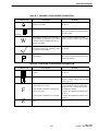
Table B-1 CHANNEL ICONS DURING CALIBRATION
Channel Icons
Description
Remedy
Other icons appear to the left of this icon as To calibrate, follow the instructions in Seccalibration proceeds.
tion B.1.4.3.
Data acquisition is in progress.
Be patient until data acquisition has finished. Each repeater takes approximately
15 to 20 seconds.
Flashing
W
The channel is writable. Data acquisition If data is not to be acquired from other
for the channel is completed. Two or more channels, continue with the write procedure
in
repeaters returned good data that may be
written to the SMC.
Data acquisition for the channel was com- Fix any repeater problems and recalibrate
pleted but not successful. No timing values the channel.
are written for this channel.
The channel is reverted; calibration could
not be started.
Fix the problems that have caused the channel to revert. Unrevert the channel. Then,
calibrate the channel.
Table B-2 REPEATER ICONS DURING CALIBRATION
Channel Icons
Description
Remedy
Data acquisition has not occurred for the
repeater.
To calibrate, follow the instructions in Section B.1.4.1.
Data acquisition was successful.
If data is not to be acquired from other
channels, continue with the write procedure
in Section B.1.4.3 .
Data acquisition failed. Possible causes:
1. The repeater is reverted.
F
Z
1. Fix the problems that have caused the
repeater to revert. Unrevert the repeater.
2. The Channel Controller’s Timing Tone Recalibrate the channel.
2. Perform the alignment described in SecGain is set too low.
tion B.1.2.
3. The repeater’s threshold is set too high. 3. Perform the alignment described in Section B.1.2.
The repeater’s threshold value is set incor- Perform the alignment described in Section
rectly.
B.1.2.
B-5
May 1998
Part No. 004-0690-303
PAST PROCEDURES
B.1.4.3 WRITE PROCEDURE
Click the Write button to write the timing values
to the repeaters’ SMCs. Only repeaters that have OK
icons are written. If a channel has a check mark icon,
none of that channel’s repeaters are written. A flashing icon next to the channel name indicates that writing is in progress. An information alarm occurs as
each repeater is written.
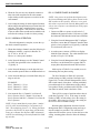
SITE 2
SITE 1
The Write process writes the data for all channels
that display the W icon every time the Write button is
clicked. For example, if data has been acquired for
Channel X and the button is clicked, the data is written
to all the repeaters that show OK and are associated
with Channel X. If data is then acquired for Channel
Y and the Write button is clicked, the data is written to
all the repeaters that show OK and are associated with
Channels X and Y. To avoid rewriting data, close and
reopen the Manual Calibration dialog box after clicking the Write button.
SITE 3
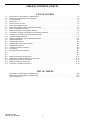
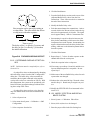
In overlap areas, a distorted audio signal is heard
when two or more signals are received if there is a
time offset between the signals.
B.1.5 DETERMINE AND SET OVERLAP OFFSET
Figure B-4 OVERLAP OFFSET CONCEPT
In a Simulcast System, repeater coverage areas
overlap. A radio in the overlap area may receive two
or more signals. If the signal strengths are similar, the
radio’s receive circuits capture two or more signals.
The signals often will not arrive at precisely the same
time; therefore, the audio from the radio is distorted.
The amount of distortion is more noticeable in some
locations than in other locations, depending on the distance between the location and each site that is heard.
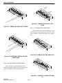
SITE 1
The distortion pattern of the overlap area can be
changed with overlap offsets. Initially, repeaters are
calibrated so that they all transmit at the same time.
An overlap offset causes a repeater to transmit a little
earlier or a little later than the initial calibration time.
A change in the time of transmission changes the time
the signal arrives at the location and therefore change
the amount of distortion at each location.
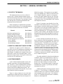
Best reception is where multiple signals are
received at precisely the same time.
SITE 1
Offset 0
SITE 2
Offset 0
50µs
50µs
Time to travel
Initial calibration sets all repeaters to
transmit at the same time.
Overlap offset values are set in increments of 1
microsecond. For a rule of thumb: A radio signal
travels at 0.186 mile per microsecond, so a setting of 5
microseconds moves the distortion pattern approximately 1 mile. Figure B-4 illustrates the overlap offset
concept.
May 1998
Part No. 004-0690-303
SITE 2
Figure B-5 NO OFFSET
B-6
PAST PROCEDURES
4. Click the Read button.
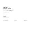
SITE 1
5. From the Buffer Delays section, make a note of the
calibrated Buffer Delay values from the User
Defined sets. These values need to be re-entered at
the end of these instruction.
SITE 2
6. Modify the Buffer Delay value.
Best reception can be moved by setting an
overlap offset. The offset offset also affects
overlap areas with other repeaters.
SITE 1
Offset 5
SITE 2
Offset -5
45µs
55µs
Time to travel
The delay at Site 1 is offset by 5 µs more and
the delay at Site 2 is offset by 5 µs less than
the initial calibration.
•
Each increment changes the transmit time 1 microsecond, which is the amount of time it takes the signal to travel approximately 0.186 mile. The signal
travels approximately 1 mile in 5 increments time.
•
Incrementing in a positive direction increases the
delay before transmitting, which moves the distortion pattern closer to the repeater. Incrementing in a
negative direction decreases the delay before transmitting, which moves the distortion pattern farther
from the repeater.
7. Click the Write button.
Figure B-6 FIVE MICROSECOND OFFSET
8. Repeat Steps 3 - 7 above for other repeaters on the
channel that affect the overlap area.
B.1.5.1 DETERMINE OVERLAP OFFSET VALUES
9. Check the reception in the overlap area.
10.If necessary, repeat Steps 3-4 and 6-9 until the overlap area distortion pattern is acceptable. Do not
repeat Step 5.
NOTE: Calibration must be completed first, refer to
Section B.1.4.
Overlap offset values are determined by changing
the buffer delay values from the SMC Configuration
dialog box. The buffer delay values must then be
returned to their original calibrated values and the
overlap offset values are entered in an .INI file. With
this arrangement, the system can be periodically calibrated for minor propagation changes without affecting the overlap offset values.
11. Make a note of the new Buffer Delay values for each
repeater that was changed.
12.Subtract the values noted in Step 5 from the values
noted in Step 11. Results may be negative or positive.
13.Modify the SITECTR.INI file as instructed in Section B.1.5.2
Overlap offset values apply to a site; therefore,
only one channel needs to be used to determine the
values.
B.1.5.2 MODIFY SITECTR.INI AND RECALIBRATE SYSTEM
1. Select a System icon.
1. Select System -> Calibration. Edit offsets.
2. Select menu item System -> Calibration -> SMC
Configuration.
2. Select (click on) the site to be changed.
3. Select a repeater from the list.
3. Enter the proper offset in the Site Settings box.
B-7
May 1998
Part No. 004-0690-303
PAST PROCEDURES
4. Click on the SAVE button.
B.2.3.1 SYSTEM SETUP
5. Repeat Steps 2, 3 and 4 as needed for other sites.
1. At the Network Manager, record the SMC data
gain levels for the channel in the Channel Controller
used for the test and reset them to 0. This is done by
selecting the System Icon, then select the System
pull down and then go into SMC Configuration.
Write the information.
6. Close the Edit Offsets box.
7. Recalibrate every channel in the system.
B.2 MANUAL TIME AND PHASE PROCEDURES
2. While in the SMC Configuration, set the delay of
each Remote Site repeater to be used to 500 µs.
B.2.1 GENERAL
3. Start 2000pgmr (with the -e option) and go to the
RAW TX/RX (Mode 2).
This Section describes manual procedures for
timing and phasing an E.F. Johnson Simulcast Radio
System. It will produce the same result as the procedures discussed in Section 2. It may also be used after
the procedures of Section 2 have been implemented in
order to verify the results.
4. Enter: 10 xx 08 xx 00 BF 04
Where: xx is the repeater number.
This starts the 1 burst-per-second timing signal on
the channel.
B.2.2 ADDITIONAL TEST EQUIPMENT REQUIRED (TO SECTION 2.2)
•
•
•
•
•
•
•
•
•
5. Shut down all the channels that interfere with the
test. This can be done manually or using
Network Management.
800 MHz Omnidirectional Antennas, 2 each
Maxrad Model BMUF 8063 (mag mount)
SINAD meter
Appropriate cables/connectors
Simulcast Test Set
Oscilloscope
800 MHz Directional Yagi Antennas, 2 each
Sinclair Model SRL 406-1
Tire mount antenna mast
Version 8.35 beta test Repeater Programming Software
SED Box (two total)
Example: Timing a three site system.
•
On Site-1, Channel-1 is used for the test, turn off
Channel-2 and Channel-3.
•
On Site-2, Channel-2 is used for the test, turn off
Channel-1 and Channel-2.
•
On Site-3, Channel-3 is used for the test, turn off
Channel-1 and Channel-2
Do not attempt to time two or more at one time or
severe interference will be experienced on the oscilloscope screen (align 1 vs. 2, then 2 vs. 3).
B.2.3 SYSTEM AUDIO TIMING
6. Drive to the location designated by Applications
Engineering for overlap alignment.
NOTE: The following procedures require two or three
people to complete. One at the Hub Site (or Network
Manager Location), one at the Channel Controller (if
not collocated with the Network Manager) and the other in the overlap region. If other channels in the system
are functional, they may be used for two-way communication during the alignment process. Otherwise, other methods are needed. This procedure uses two or
more RF channels (a different channel at each site to be
timed). A single channel may be used, if signals are relatively equal at the test point.
May 1998
Part No. 004-0690-303
7. Drive one tire over the base plate of the antenna
mast.
8. Set up two Yagi antennas on the mast. One should
be pointed at each of two repeater sites. If the sites
are visible, the antennas may be visually pointed
toward each site’s tower. If they are not visible, use
a compass and a map to point them in the proper
direction.
B-8
PAST PROCEDURES
9. Fine tune the antenna direction to minimize interference on the oscilloscope screen.
•
Connect each antenna to the antenna jack on the two
alignment radios (the Simulcast Test Kit).
CHANNEL 1
•
Connect the discriminator output jacks of the radios
to the two vertical inputs of the oscilloscope Channel-1 and Channel-2.
CHANNEL 2
•
DELAY
OFFSET
One radio should be tuned to Site-1 Channel-1, and
the other to Site-2, Channel-2.
OSCILLOSCOPE
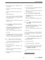
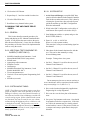
B.2.3.2 TIMING
Figure B-3
1. Trigger the oscilloscope off Channel-1. Carefully
adjust the trigger level for a stable display. A good
clear display of two burst signals should appear, one
slightly ahead of the other. The difference should be
less than a few hundred microseconds. If one signal
is persistently weak and noisy, it may be necessary
to relocate. Stay as close as possible to the original
site so as not to skew the timing. A few hundred feet
is acceptable whereas a mile is not. Be sure to maintain a distance from large buildings, sheds, barns,
and signs. They will act as reflectors and interfere
with the signal.
3. Once the traces are close to being in sync, place the
scope in X-Y mode to show minute differences in
timing. A straight diagonal line, with no perceivable ellipse shows a well-timed system (see Figure
B-4).
2. If one of the sites is collocated with the Channel
Controller, this site should have no additional delay
added. There is a special filter that simulates the
group delay of the multiplexer channel cards and it
adds approximately 1 ms of delay. This is done by
switch settings on the SMC. It is necessary to add
approximately 800 µs of delay to the other sites to
get close to the delay of the collocated site. Use the
Network Management SMC Configuration menu to
set the delays in each repeater. By observing the
scope screen (see Figure B-3), it is possible to
observe the approximate number of microseconds
that must be added or subtracted to get the waveforms from each site even. It generally takes a large
change followed by two or more small changes.
The scope displays two traces, one from Site-1,
Channel-1 and one from Site-2, Channel-2. Notice
the delay offset. The Network Manager is used to
set delays in repeaters to sync the signals.
NEEDS MORE ALIGNMENT
CORRECTLY ALIGNED
Figure B-4
B-9
May 1998
Part No. 004-0690-303
PAST PROCEDURES
B.2.4 COARSE PHASE ALIGNMENT
4. When the first two sites are adjusted, continue to
other sites until completed in the same manner.
Adjust timing to other repeaters at each site in the
same manner.
NOTE: One person can perform this alignment once
the Network Management places phase control on the
DIP switches in the repeaters. However, it is a good
idea to have a person at the Network Management console in case a repeater is accidentally not in the proper
configuration.
5. After setting the timing for the designated location,
add or subtract the optimization correction factor for
each site. This data is supplied from a coverage
optimization program. The factors are in the form
of plus or minus microseconds and are added or subtracted to the settings of each site’s delay setting.
1. Connect an IFR to a repeater as in Section 2.5.
Modulate the generator with a 1 kHz tone at 1.5 kHz
deviation and 1 kHz data deviation from a SED Box.
B.2.3.5 NORMAL OPERATION
2. Using the Network Management SMC Configuration menu, ensure that the Channel Controller data
gain is set at its original level (Typically 1) and that
it is not shut off (not set to 0).
When the alignment is complete, restore the system back to normal operation.
1. When done timing a channel, enter the following in
2000pgmr (with the -e option) in Raw Rx/Tx::
10 xx 08 xx 00 BF 01
Where: xx is the repeater number.
3. At each repeater, connect a SED box to display
Multi-Net data (decode). The cable should be connected to J58, pin 5 (Tx MOD).
2. At the Network Manager, set the Channel Controllers SMC data gain back to the recorded level
(Typically 1).
4. Using the Network Management SMC Configuration menu, set the Remote Site repeater SMC to
accept phase adjustment from the DIP switches.
3. At the Network Manager, or at the physical locations, turn the repeaters that were shutdown back on.
Make copies of Table B-3 (as needed) to use in
determining the best phase setting.
4. At the Network Manager, record the final delay settings at each site.
The list of numbers in Table B-3 represents
switch settings on SW4, positions 5 through 8 (see
Figure B-8). Set the Network Management to allow
DIP switch control of the phase. Starting with 0000,
proceed through all 16 combinations, noting which
ones produce steady, good data on the SED box. If the
data fades in and out, mark it bad in the Table.
EXAMPLE:
Site-1, Channel-1 = 511 µs
Site-2, Channel-2 = 330 µs
Site-3, Channel-3 = 430 µs
There will be a range of positions where there is
good data (Typically 7 or 8). If the range is an odd
number of SMC switch settings, leave the setting in
the middle. If the range is even, leave the setting on
the lower of the two middle settings.
5. Now input the Site-1, Channel-1 level into all
Site-1 repeaters, Site-2, Channel-2 level into all
Site-2 repeaters and Site-3, Channel-3 level into all
Site-3 repeaters.
NOTE: Keep in mind that the proper phase “number”
(0-255) in the Network Manager corresponds to 0°360°. The multiplying factor is 1.4. During the Phase
procedure, this needs to be input along with the delay
setting to set Remote Site Repeater SMC information
with the Network Manager instead of Remote Site SMC
dip switches.
May 1998
Part No. 004-0690-303
Read the phase adjustment from the Network
Management SMC Configuration menu and copy it
into the setting box provided. This will later be
adjusted to fine tune the system. Select this box as the
setting, returning phase control to Network Management.
B-10
PAST PROCEDURES
B.2.5 FINE DATA PHASE ADJUSTMENT
10.Bring up all repeaters. Verify that the SINAD is at
an acceptable level (typically 16 dB or better). If
not, repeat the above procedure trying Network
Management phase steps of one to pin point an
acceptable SINAD level in Step 7.
CRITICAL ADJUSTMENT
This procedure is extremely critical for proper
Simulcast operation. Failure to do it properly may
result in unacceptable noise levels in overlap areas.
11. Remove the IFR from the repeater and restore all
repeaters to normal operation.
.
1. Connect the IFR to a repeater as in Section 2.5.
Modulate the generator with a 1 kHz tone at 1.5 kHz
deviation and 1 kHz data deviation from the SED
box.
Table B-3 SMC S4 SETTINGS
Section 8 Section 7 Section 6 Section 5
180°
90°
45°
22.5°
2. Using the Network Management, disable all but two
repeaters on the channel being worked on.
0
0
0
0
0
0
0
0
1
1
1
1
1
1
1
1
0=Off 1=On
3. Travel to the location used for overlap timing
between the two repeaters for the test.
4. Connect one radio of the Simulcast Test Set to an
Omnidirectional antenna.
5. Connect the speaker/microphone output to the
SINAD meter. DO NOT connect the discriminator
output to the meter. Only the audio tone, without
data is required.
6. Record the current SINAD reading. If a service
monitor is used, use the analog meter (if available)
or set the digital reading for a slow, averaging
response.
7. Using the Network Management SMC Configuration menu, carefully start incrementing the phase of
one of the two repeaters. Do this in steps of two,
each step on the Network Management console represents 1.4°. If Noise increases and SINAD drops,
go in the opposite direction. If there is little difference, return to the original setting and perform this
procedure with the other repeater. Do not go further
than 20 units from the original setting. Keep track
of the positions and record the SINAD readings.
0
0
0
0
1
1
1
1
0
0
0
0
1
1
1
1
0
0
1
1
0
0
1
1
0
0
1
1
0
0
1
1
Good
0
1
0
1
0
1
0
1
0
1
0
1
0
1
0
1
B.2.5.6 S4 TRANSMIT LEVEL/PHASE SWITCHES
This sets the data output at a Remote Site. S4,
section 2 is the Installation Mode select. It is only on
to allow setup of the Channel Controller. While the
levels are being set this switch prevents the MAC from
sending alarms that would cause the MPC to shutdown
the Channel Controller (can be overridden by Network
Management).
8. Shut down one of the repeaters (if more than one)
and bring up another.
9. Repeat Steps 3 - 8 with the third repeater, holding
the first one steady this time.
B-11
May 1998
Part No. 004-0690-303
PAST PROCEDURES
8
SE
UR Y
CO ELA
D
7
6
8
5
1
80
4
90
6
2
45
22
LE
AB
EN
7
3
/DI
us
00
s
10
0u
s
50
0u
25
s
5u
12
us
64
us
32
us
16
1
.5
25
11.
ON
E
AT
ST /OFF
P
TU O N
SE INK
E
L
BL
SA MW
E
FIN LAY
DE
5
4
3
2
1
ON
s
8u
Figure B-10 REMOTE SITE SMC S3 SETTINGS
Figure B-7 REMOTE SITE SMC S4 SETTINGS
B.2.5.11 S1 SIGNAL PATH SWITCHES
This 8-section switch routes the audio/data to and
from the MAC to and from the microwave link. Input
is for a Channel Controller and output is for a Remote
Site.
8
7
6
5
8
4
7
3
6
5
2
1
NE
TO
A
AT
zD
TE
TA ING
H
S
5
P
12
AL
TU
SE SIGN
E
BL
TA
ISA S DA
D
/
S
LE /PA
AB TOP
N
E
S
4
CC
ON
4
1
CC
3
2
2
CC 3
CC
1
R
S4
RS
3
RS
ON
2
R
S1
Figure B-12 REMOTE SITE SMC SWITCH S1
Figure B-8 REPEATER CONTROLLER SMC
S4 SETTINGS
8
7
6
4
CC
B.2.5.9 S3 FINE DELAY/COURSE DELAY
These switches are the manual input for the
timing delay setting at the Remote Site repeaters only
(can be overridden by Network Management).
5
4
1
CC
3
2
CC 3
CC
2
1
4
RS
RS
3
RS
ON
2
R
S1
Figure B-13 CHANNEL CONTROLLER SMC
S1
May 1998
Part No. 004-0690-303
B-12