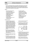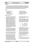
1
K1EL
K42 CW Keyboard/Reader Kit Assembly Guide
Revision A.5
Introduction
This document will describe how to assemble and checkout a K42 Keyboard/Reader Kit. The assembly of the
K42 is not difficult, but probably not a good “first kit”. Before you start working on the kit you will need to gather
the following items
1)
2)
3)
4)
5)
6)
7)
8)
A low wattage (40W) soldering iron or pencil or temperature controller solder station.
Good grade of Rosin core solder, Please do not use ACID CORE Solder !!
A few pieces of hook up wire
Good pair of wire cutters, small pliers, assorted screwdrivers, and a 5/64” Allen wrench
A Volt Ohmmeter or DVM is required for several assembly steps
A magnifying glass is very helpful
Power supply providing a voltage between 8 to 13 VDC (9VDC is optimum) at about 250 ma.
Audio signal generator or radio receiver with a calibrate function.
It is very important to take your time and to carefully follow the instructions and assembly photos.
These instructions will take you through a step by step process that will test portions as you go. This will make
debugging much easier since if a problem arises you will be able to locate the source and repair it right away.
Please don’t assemble the kit in a manner other than as described, the order of the steps is very important from
a mechanical perspective and if you don’t follow them you can end up with a kit that can’t be completed.
These instructions assume you have basic electronic kit building experience and can identify different types of
electronic components. Photos are provided which will greatly aid in assembling the kit correctly. Additional info
is provided in RED. The biggest enemy of kit success is poor soldering, so please take care with each solder
joint, and use just enough heat to get a good connection. A good joint should be both shiny and smooth.
Bill of Materials
The bill of materials is listed below. The first step is to inventory and identify all parts ahead of time. This will
allow the assembly to proceed smoothly. The parts are packed in separate compartments; try not to mix the
resistors in different compartments together, the precision resistors are packed by themselves. You might want
to verify resistor values with an ohmmeter if you are color impaired like I am. We try to do a good job putting the
kits together but sometimes we make mistakes, let us know if you are missing any parts.
Reference Des.
Qty
Part Description
Package
Other Info
Check Off
C1,C2,C4,C5
C16,C17
6
.001uF Capacitor (102)
Ceramic Disk
.2” spacing
_________
C3,C9,C11,C14
4
.1uF,Capacitor (104)
Ceramic Disk
.2” spacing
_________
C6,C12,C18
C19,C20,C21
6
.01uF,Capacitor (103)
Ceramic
.2” spacing
_________
C10,C13
2
.012uF Mylar Cap (123)
Mylar film
.2” spacing
_________
C7, C8
2
4.7uF Electrolytic Cap
Radial
.1” Spacing
_________
C15
1
100uF Electrolytic Cap
Radial
.1” Spacing
_________
R1
1
5K Trimmer Potentiometer
R5
1
68 Ohm Resistor
1/4 Watt
Blu Gray Blk
_________
R13,R14,R15,R16,
4
470 Ohm Resistor
1/8 Watt
Yel Violet Brn
_________
R2,R3,R4,R6,R11,
R12,R17,R18,R21
9
4.7K Ohm Resistor
1/8 Watt
Yel Violet Red
_________
R10
1
47 ohm
1/2 Watt
Yel Violet Blk
_________
R9
1
6.65K Ohm 1% Resistor
1/8 Watt
Blue Axial
_________
R8
1
33.2K Ohm 1% Resistor
1/8 Watt
Blue Axial
_________
R7
1
66.5K Ohm 1% Resistor
1/8 Watt
Blue Axial
_________
K42 Kit Assembly Guide RevC PCB
6/13/2014
_________
Page 1
K1EL
K42 CW Keyboard/Reader Kit Assembly Guide
Revision A.5
U1
1
Solid State Relay
AQW210EH or LAA125
8 pin DIP
_________
R19, R20
2
470 Ohm for LAA125
or 620 Ohm for AQW210
1/8 Watt
U2
1
16F688 Keyer PIC
14 pin DIP
U3
1
CY8C27143 PSoC
8 pin DIP
socketed
_________
U4
1
TLC2272/TS922/LMC6482
Dual Op Amp
8 pin DIP
no socket
_________
U5
1
16F688 Console PIC
14 pin DIP
µP, socket
_________
U6
1
24LC32A Serial EEPROM
8 pin DIP
no socket
_________
U7
1
12F508 LED Driver PIC
8 pin DIP
µP, no socket
_________
L1,L2
2
1uH,Inductor
Ferrite Bead
_________
Q1
1
2N2222 Transistor
TO-92
_________
Q2
1
2N7000 Transistor
TO-92
_________
D1,D2,D3,D4,D5,D6
6
CWR Tuning LED
Right Angle
Yel Violet Brn
Blue Red Brown
_________
_________
white dot, skt’d _________
Red or Green
_________
D7
1
1N4001 Diode
DO-41
_________
VR1
1
LM7805 5 Volt Regulator
TO220
_________
DP1
1
Sunlike SD1602H
LCD Display
SP1
1
Mini Speaker
J1,J3,J4
3
Stereo Phone Jack
1/8 Inch Jack
J2
1
Keyboard Connector
PS2 6 Pin DIN
_________
J5
1
Power Connector
2.5 mm female receptacle
_________
P1
1
Power Connector
2.5 mm male plug
_________
ENC1
1
Rotary Encoder
Panel Mount
_________
MISC
1
Hex Nut for Rotary Encoder (on encoder)
_________
MISC
1
Flat Washer for Rotary Encoder (on encoder)
_________
MISC
1
K42 Enclosure
_________
MISC
1
Control Knob
Plastic 1/4” shaft
_________
MISC
4
Rubber Feet
Press in
_________
MISC
1
16 pin Header
Right Angle
MISC
2
1/4” plastic spacers
LCD Mounting
_________
MISC
3
4-40 Hex Nuts
w/lock washers
_________
MISC
1
K42 Rev C PC Board
MISC
4
4-40 1/4” Screws
Black for enclosure cover
_________
MISC
5
4-40 1/4” Screws
For heatsink and PCB mounting
_________
MISC
2
14 pin DIP socket for U2 and U5 (Keyer & Console PICs)
_________
MISC
2
8 pin DIP socket for U3 (PSoC) and U1 (Opto SSR)
_________
MISC
1
10” length of hook up wire
_________
MISC
1
Heatsink
_________
K42 Kit Assembly Guide RevC PCB
PCB Module
_________
_________
6/13/2014
AF, Key, Pdl
Tin solder
_________
_________
_________
Page 2
K1EL
K42 CW Keyboard/Reader Kit Assembly Guide
Revision A.5
Step By Step Assembly Instructions
1)
2)
After inventory, carefully inspect the PCB for defects such as solder shorts or breaks due to over etching.
We buy high quality boards and rarely have any problems but it's easier to find one now before we solder
anything to the board. Use the PCB layer pictures on pages 28 and 29 as a reference. There is also a
Placement by Part Value picture on Page 30 which is very helpful.
We will start with the power supply, install and solder:
___ Power Connector J5
___ Voltage Regulator VR1 LM7805 TO-220
Capacitors:
___ C7 (4.7uF electrolytic) may be black or grey in color
___ C8 (4.7uF electrolytic)
___ C15 (100uF electrolytic)
___ C11 (.1uF) 104 Dipped
___ C14 (.1uF) 104 Dipped
___ D7 (1N4001)
___ Solder and trim leads
The long lead of the electrolytic caps (C7,C8,C15) is positive and must go into the square pad. If you are
not going to use an on/off switch (optional) solder a jumper between pads S1 and S2. You can always
remove the jumper and add a switch later. Observe the band on D7 and line it up to match the silkscreen.
K42 Kit Assembly Guide RevC PCB
6/13/2014
Page 3
K1EL
3)
K42 CW Keyboard/Reader Kit Assembly Guide
Revision A.5
Once these parts are soldered in place, make up a power supply cable to test the board. A mate to J5 is
included in the kit. Solder two wires to the connector, plus lead on the center pin. If you have a 9 to 13VDC
supply with a 2.5mm connector, that will work fine. Current rating must be greater than 100 ma.
Double check that the center pin of the power connector is postive with respect to the shell and then plug it
into J5. The K42 does have a polarity protection diode but it’s worth the extra step to make sure the cable is
right. You should see +5V on the test point pad closest to the left of R10. Now Disconnect Power.
4)
Next step is to install parts to test the keyer portion of the K42.
___ Install two 1/8 inch jacks J1 and J3 READ BELOW BEFORE SOLDERING!!
Tack solder the rectangular hole first making sure the connector is aligned correctly. Use the silkscreen
guide on the top of the board to center the connector as close as you can. Also insure the front of the
connector is flush with the PC board edge. Solder the remaining two holes. It’s important to align these
connectors correctly so that they will fit properly in the metal enclosure.
After installing both connectors
___ Install and solder three IC sockets at sites: U1, U2, and U5.
Be sure to align the dimple in the socket with the silkscreen as illustrated :
Now install and solder the following resistors and transistor:
1
8
___ R19 and R20 refer to note in the bill of materials
___ R2, R3, R11, R12, R17, R18, R21 (4.7K) Yellow Violet Red
___ R5 (68 ohm) Blue Gray Black
___ Q1 2N2222 transistor (TO92) Align flat side with silkscreen as shown:
Now install and solder capacitors and trim all component leads:
___ C1, C2, C4, C5, C16, C17 (.001uF) 102 Disc
___ C19, C20, C21 (.01uF) 103 Disc
Install mini speaker SP1, observe polarity marker on the side of the part, and place the plus side pin into one
of the square pads. There are four holes, pick the pair with spacing that matches your speaker.
___ SP1
K42 Kit Assembly Guide RevC PCB
6/13/2014
Page 4
K1EL
5)
K42 CW Keyboard/Reader Kit Assembly Guide
Revision A.5
Install Keyer PIC, U2
___ Install U2 (the 14 pin DIP IC with the silver dot. This is the keyer PIC.
For all IC installs please observe the pin 1 dimple on the IC and orient it to match the silkscreen and socket.
Look ahead at the picture above. To get an IC to fit into its socket you will have to bend the leads to a 90
angle by laying the IC on its side on a flat surface and folding the pins in slightly.
6)
Next step is to install and test the Console logic.
___ Install and solder Keyboard connector J2
___ Install the two leaded Ferrite Beads L1 and L2
___ Install Cap C3 (.1 uF) 104 Dipped
___ Install Serial EEPROM U6 (no socket), solder and trim component leads
___ Install Console PIC U5 in its socket.
K42 Kit Assembly Guide RevC PCB
6/13/2014
Page 5
K1EL
K42 CW Keyboard/Reader Kit Assembly Guide
Revision A.5
7)
Test the Keyer PIC circuit: Plug your keyer paddle into J3, it’s assumed that your paddle set cable has an
1/8” stereo plug. Turn on power and when you press the paddles you should hear dits one way, dahs the
other, and alternating dits/dahs when both are pressed. Turn off power supply.
8)
Test the keyboard and Console PIC circuit: Plug a PS/2 keyboard into J2. When power is turned on the
keyboards light will turn on then off and you will hear an “R” in sidetone. When you type letters on the
keyboard they will be sent in sidetone.
___ Turn off power, install solid state relay (AQW210E or LAA125) in 8 pin DIP socket U1, re-apply power.
While keying, measure the resistance across the tip and shield of connector J1. At key down you will see a
low resistance, at key up you will see an open circuit. Polarity doesn’t matter since U1 acts as a relay
contact. REMOVE POWER and disconnect the paddles.
9)
Now we will install the CWR interface and run a few more basic tests. We install the LCD display last to
reduce the risk of damage due to mishandling
We’ll start with the CWR LED tuning array:
___ Install Resistors R14 and R15 (470 ohm) Yellow Violet Brown
___ Install Cap C18 (.01uF) 103 Disc
___ Install IC U7 (follow precautions called out in Step 6)
___ Install six LEDs D1-D6 read below for details. Solder and trim component leads
We want to install the LEDs so that they are all even with the front edge of the board and there is equal
space between them. The best thing to do is start in the middle and work your way right and left. Put in D3
K42 Kit Assembly Guide RevC PCB
6/13/2014
Page 6
K1EL
K42 CW Keyboard/Reader Kit Assembly Guide
Revision A.5
first, tack solder one lead and tweak the placement to get the front edge aligned right. Then install D4 the
same way and space it so that D3 and D4 are not touching and there is about 1/32” gap between them. Go
back and forth D3, D4, D5, D2, D6, and D1. It should look at least as good as the picture below when you
are done. Please spend extra time with this because you will see the bodies of the LEDs through the front
panel and the better they look, the better the whole assembly will look.
10) Check out of the display is pretty easy. Just turn power on, and the LEDs will run a self test pattern. D1->D2>D3->D4->D5->D6 then in reverse. One LED may remain on when the test is complete.
11) The next step should be done carefully, we will install the AF active filter of the CWR
___ Install and solder 1/8 inch connector J4 (observe precautions in Step 4 !!)
___ Install resistor R6 (4.7K) Yellow Violet Red
Note about precision resistor installation. These are the three blue colored resistors. The color code is very
hard to read on these, I insist that you use either a DVM or multimeter to sort them out. They are far enough
apart in value so it’s pretty easy. Note that depending on your meter’s calibration and the tolerance of the
resistors, you probably will not read the exact value but all we are trying to do is sort them into three:
6.65K, 33.2K, and 66.5K
___ Install precision resistor R9 (6.65K)
___ Install precision resistors R8 (33.2K)
___ Install precision resistors R7 (66.5K)
___ Install capacitor C9 (.1uF) 104 dipped
___ Install capacitor C12 (.01uF) 103 Disc
___ Install U4 TLC2272 op amp, then solder and trim leads
___ Install Capacitors C10, and C13 (.012 uF) dipped
___ Solder carefully (it’s easy to bridge pads here) and trim component leads
Note: R13 is an optional install, see page 23 for more information.
K42 Kit Assembly Guide RevC PCB
6/13/2014
Page 7
K1EL
K42 CW Keyboard/Reader Kit Assembly Guide
Revision A.5
12) We can’t test the AF filter until the PSoC processor is installed, we will do that now
___ Install Cap C6 (.01uF) 103 Disc
___ Solder and trim component leads
___ Install and solder 8 pin socket at U3
___ Install PSoC microprocessor, 8 pin DIP (silver dot) at U3
13) Now it’s time to check out the CWR tone filters. Connect an audio frequency generator or receiver audio
output to the AF input on the K42 board, this requires an 1/8” mono or stereo plug, the audio connection will
be on the tip and sleeve of the connector. The level should be around .5V peak to peak, preferably a high
impedance output (600Ω). You can use speaker audio output but be careful to start with a low volume
setting. If you are using a receiver, turn on calibrate or tune in a carrier signal to get a beat note. If you are
using a signal generator set it close to 690 Hz. You will need to attach your keyboard. Power up the K42 and
K42 Kit Assembly Guide RevC PCB
6/13/2014
Page 8
K1EL
K42 CW Keyboard/Reader Kit Assembly Guide
Revision A.5
enter ALT-F1 to enable CWR mode. Adjust the receiver or signal generator frequency up and down slowly
until you see some activity on the LED display. You may have to adjust the audio level. As you tune you
will first see LEDs light on the left side and then peak to the right as you tune through 690 Hz. The maximum
swing should be at 690 Hz. If your audio level is too low you may not see a full LED swing. If the level is too
high you may see a very broad tuning peak. If you are having problems, read through the theory of
operations and check the signal path through the filter. TP1 and TP2 are useful for this (see schematic) TP1
is the output of the on board active bandpass filter while TP2 is the output of the PSoC’s internal tone
detector. If you do not see a very distinct peak at TP1 when sweeping the frequency this may indicate that
the the 1% active filter resistors are in the wrong place. The PSoC filter is hard coded to respond at 690 Hz
and you will see a high level at TP2 at the peak. When the filter is working properly the peak that you
measure at TP1 will be very close to the high level at TP2, both at 690Hz.
14) Next step is to install the LCD display and associated components:
___ Install and solder resistor R4 (4.7K ohms) Yellow Violet Red
___ Install and solder resistor R16 (470 ohms) Yellow Violet Brown
___ Install and solder resistor Q2 (2N7000) TO92 transistor
K42 Kit Assembly Guide RevC PCB
6/13/2014
Page 9
K1EL
K42 CW Keyboard/Reader Kit Assembly Guide
Revision A.5
___ Install and solder resistor R10 (47 ohms) ½ W Yellow Violet Black
___ Install and solder trim pot resistor R1 (5K ohms)
NOTE: the LCD module uses a delicate film ribbon cable which can be easily torn or damaged. When
picking the display up try to hold it by the sides avoiding contact with the ribbon cable.
These next steps are a little tricky and you have to take your time on this. First of all attach the right angle 16
position header to the LCD module EXACTLY as shown in the following pictures. It is a little tricky to get the
K42 Kit Assembly Guide RevC PCB
6/13/2014
Page 10
K1EL
K42 CW Keyboard/Reader Kit Assembly Guide
Revision A.5
header into the display holes, due to the plastic spacer on the display module. Angle it slightly and it will
slide in place. Align it so the connector seats flat on the display PCB and make sure you put it on the correct
side. I get it aligned the best I can and then solder one center pin, then I inspect it and make adjustments
while reflowing the solder connection. Once I get it perfect I solder all of the pins.
K42 Kit Assembly Guide RevC PCB
6/13/2014
Page 11
K1EL
K42 CW Keyboard/Reader Kit Assembly Guide
Revision A.5
15) Now install the four rubber feet into the bottom of the chassis. They can be uncooperative but they will fit,
just twist and push in at the same time.
16) Place two ¼ inch white plastic spacers on the front panel studs as shown below
K42 Kit Assembly Guide RevC PCB
6/13/2014
Page 12
K1EL
K42 CW Keyboard/Reader Kit Assembly Guide
Revision A.5
17) Insert the LCD display assembly into the main PCB so that is faces forward.
18) Carefully slide the board with display into position on the chassis base. The board should fit evenly on the
four threaded posts of the front panel.
K42 Kit Assembly Guide RevC PCB
6/13/2014
Page 13
K1EL
K42 CW Keyboard/Reader Kit Assembly Guide
Revision A.5
19) Install all four ¼ inch mounting screws to securely hold PCB in place.
20) Adjust the display so the threaded studs are centered in the display’s mounting holes as shown.
K42 Kit Assembly Guide RevC PCB
6/13/2014
Page 14
K1EL
K42 CW Keyboard/Reader Kit Assembly Guide
Revision A.5
21) Then place a 4-40 nut/lockwasher on each side and tighten just enough to hold the display in place. Check
to be sure that the display is aligned horizontally by looking at it through the front panel window. You have
wiggle room for fine adjustment since the display is a loose fit on the threaded studs.
22) Double check that the K42 main PC board is firmly seated on the enclosure standoffs and that the display is
held firmly in place by the 4-40 nuts. Now very carefully sneak in with your soldering iron and tack solder two
pins on the header to the K42 main board as shown. Solder the fourth pin in from each end, being careful
that the barrel of your soldering iron does not come in contact with anything.
K42 Kit Assembly Guide RevC PCB
6/13/2014
Page 15
K1EL
K42 CW Keyboard/Reader Kit Assembly Guide
Revision A.5
23) Now remove the 4-40 screws and nuts and carefully remove the LCD display/K42 PCB assembly.
24) Now solder the remaining header pins from the bottom of the K42 board. SOLDER THE TACKED JOINTS
LAST to preserve your alignment.
K42 Kit Assembly Guide RevC PCB
6/13/2014
Page 16
K1EL
K42 CW Keyboard/Reader Kit Assembly Guide
Revision A.5
25) Remove the thin protective film from the front of the display.
Display assembly completed !
K42 Kit Assembly Guide RevC PCB
6/13/2014
Page 17
K1EL
K42 CW Keyboard/Reader Kit Assembly Guide
Revision A.5
26) To test the LCD simply apply power and you should see a ‘sign on’ message displayed. You may see an ‘N’
between PvA and CW. If the display is blank adjust the LCD contrast trimmer R1 until the display appears.
Carefully re-adjust the trimmer R1 to get the best display appearance. The sign on display automatically
clears after a few seconds so you may need to cycle power a few times to complete the contrast adjustment
procedure. The display backlight is initally set to the on state.
27) It’s time to attach the rotary encoder. Before doing so, make sure the encoder shaft fits into its mounting
hole in the chassis. You may need to remove the paint on the inside of the hole to get a good fit, I use large
screw driver blade and carefully ream the hole to clear the extra paint. An Xacto knife blade will also work
but be careful that metal shards do not get into the electronics.
28) Prepare five wires, two are 1 inch long the remaining three are 2 inches long. Strip and tin both ends as
shown in the picture.
K42 Kit Assembly Guide RevC PCB
6/13/2014
Page 18
K1EL
K42 CW Keyboard/Reader Kit Assembly Guide
Revision A.5
29) Next tin the five leads on the encoder and attach the five wires, short ones to the side with two lugs (X1 and
X2) and the three long wires to the side with three lugs. ( E1, E2, and E3).
E1
X1
E2
E3
X2
The drawing above shows how the wires should be connected to pads on the K42 PCB board. E1, E2 and
E3 are the encoder outputs while X1 and X2 are the encoder’s pushbutton switch connections
30) Solder in the X1 and X2 wires first
K42 Kit Assembly Guide RevC PCB
6/13/2014
Page 19
K1EL
K42 CW Keyboard/Reader Kit Assembly Guide
Revision A.5
31) Then solder the remaining three wires: E1, E2, and E3
32) It’s easy to test the encoder, power up the K42 and turn the encoder, you should see the current WPM value
displayed on the upper left side of the display. The display will blank a few seconds after you stop turning
the encoder.
33) Re-install the PC board assembly into the chassis. First make sure the display spacers and washers are
installed as per step 13. Then carefully fold the board back into the chassis front side first on to the display
studs then second align the board with the base mounting studs. Install and tighten the four silver 4-40
board mounting screws. Our experience has shown that it is not necessary to reinstall the two display hold
down nuts. The soldered header is mechanically strong and is all that is needed to support the display. More
often than not, builders will over tighten the nuts and damage the display or under tighten them so they work
their way loose and fall on the board causing a damaging short circuit. Bottom line, leave the display
spacers, washers, and nuts off.
34) The encoder is mounted with one hex nut and one flat washer. The washer and nut both go on the front of
the unit. Reference the picture above to see how this is done. You might want to put a spacer on the inside
so the control knob will rest closer to the enclosure but that’s up to you. Be careful when tightening the nut,
K42 Kit Assembly Guide RevC PCB
6/13/2014
Page 20
K1EL
K42 CW Keyboard/Reader Kit Assembly Guide
Revision A.5
it’s easy to slip and scratch the front panel. Now attach the rotary encoder knob using a 5/64 inch Allen
wrench.
Completed base assembly front view
35) Attach heatsink to 5 volt regulator as shown:
K42 Kit Assembly Guide RevC PCB
6/13/2014
Page 21
K1EL
K42 CW Keyboard/Reader Kit Assembly Guide
Revision A.5
36) Now is the time to give the K42 a good workout, go through the Quick Start section of the K42 manual and
then try out all of the commands and message features. You might want to take some time now to make up
any interconnecting cables you may need, The following diagram shows the connector layout on the K42
rear panel. A mating power supply connector is included with the kit, as well as two mono 1/8 plugs. Note
that stereo plugs are shown in the drawing below. A stereo plug is only required if you want to use PTT or
two keying ports on the KeyOut jack.
Audio
In
PWR
KBD
KeyOut
AF
Dit
Key
N/C
Dah
PTT
Gnd
Gnd
Gnd
Plus
Gnd
PDL
8-14 VDC
K42 Kit Assembly Guide RevC PCB
Audio
Input
6/13/2014
Iambic
Paddle
PS/2
Keyboard Key Line
to XCVR
Page 22
K1EL
K42 CW Keyboard/Reader Kit Assembly Guide
Revision A.5
37) To install the top cover, reference the following picture. Angle the top cover and get the rear connectors to
start to go into the cover. Then fold the cover down to meet the front panel and push it forward so the three
1/8 inch connectors poke out the back evenly. Install the four black 4-40 screws to hold the cover in place.
Completed Unit Front View
K42 Kit Assembly Guide RevC PCB
6/13/2014
Page 23
K1EL
K42 CW Keyboard/Reader Kit Assembly Guide
Revision A.5
Completed Unit Rear View
R13 Information
This is an optional install and is not required for normal operation of the K42. R13 routes post
filter audio to the ring of Audio In jack on the back panel. The intent was to provide a way for the
user to extract in band audio from the K42 and feed it to an audio amplifier. This allows the user
to hear peaked CW at the K42 decode frequency making it slightly easier to tune and decode a
CW station. In practice it is not much of an advantage due to the extra cabling, shielding, and the
necessity of an external audio amplifier. Unless you have a definite plan to use this feature we
recommend leaving R13 out.
K42 Kit Assembly Guide RevC PCB
6/13/2014
Page 24
K1EL
K42 CW Keyboard/Reader Kit Assembly Guide
Revision A.5
CW Keyboard Theory of Operation
This section will cover the CW keyboard portion of the K42. It can be helpful to read through this to get familiar with
the circuitry if you are debugging the K42.
As shown in the block diagram below, two PIC processors share the task of converting keystrokes to Morse code.
U5, the console PIC, is responsible for retrieving keystrokes from the keyboard and determining what to do with them.
U2 is the Keyer PIC which is controlled by the console PIC, its main task is to generate Morse code and monitor the
keyer paddle inputs. The two PICs communicate over a serial interface running at 9600 baud. The Keyer PIC throttles
the Console PIC via in-band flow control. A 4-kilobyte EEPROM memory, connected to the Console PIC’s SPI
interface, stores up to 12 messages, system settings, and holds the keyboard type ahead and LCD display buffers.
Opto
coupler
Keyboard
U5
Console
EEPROM
M emory
Serial I/F
U2
Keyer
Key
PTT
Speaker
LCD
Display
Serial I/F
Keyer Paddle
AF Input
CWR
Figure 1 - K42 CW Keyboard Block Diagram
There are two types of data sent from the Console to the Keyer: Commands and Data. Commands modify the K42's
operation in some way; changing operating speed, turning off sidetone, recording a message, etc. Data are letters,
numbers, or prosigns that are to be sent in Morse. Data is processed differently than commands. Data is put into a
type ahead buffer that allows the user to type faster than the Morse is being sent. The size of this buffer is about 200
characters and is a FIFO buffer (First In First Out) meaning that characters are taken out in the order they were put
in. Since there can be a considerable delay from keyboard input to Morse output, commands bypass the input FIFO
and are sent to the Keyer PIC immediately. This allows changes to be made while sending is underway.
Key
Processor
Key Input
Command
Bypass
FIFO
Output to Keyer PIC
Figure 2 – Output FIFO Block Diagram
Since there are cases when you don't want commands to take effect immediately, the K42 buffers certain commands.
This means that the command is placed in the typeahead buffer and won’t be acted on until it comes out. An example
of the use of a buffered command would be to send two words at two different speeds, the first at 15 WPM and the
second at 20 WPM. By placing a buffered speed command between the words the speed will not be changed until
the first word is completely sent. Not all, but many of the immediate commands can be entered as buffered
commands. Most often, buffered commands are used in messages.
Getting back to the block diagram, the paddle inputs are connected to the Keyer PIC, the paddle takes priority over data
coming in from the keyboard. A paddle press will cause the FIFO buffer to be cleared. This allows you to cancel a
message and start sending by paddle right away. As mentioned before, the keyboard is connected to the Console PIC
since its input generally has to be buffered in the EEPROM. The LCD is also connected to the Console to allow keyboard
data and command prompts to be displayed. The K42 keeps two separate display buffers in EEPROM, one that tracks
keystrokes as they are entered and a second which shows data as it is being sent by the Keyer PIC.
K42 Kit Assembly Guide RevC PCB
6/13/2014
Page 25
K1EL
K42 CW Keyboard/Reader Kit Assembly Guide
Revision A.5
The Keyer PIC has three outputs, KEY, PTT, and sidetone. Both the KEY and PTT outputs are optically isolated from K42
power and ground and are open collector, in most cases these can switch the transmitter inputs directly. Full control over
PTT is provided to compensate for transmit changeover delay and hold keying between letters and words. The
optocoupler may be replaced by a solid state relay which allows the K42 to key practically any transmitter, vacuum tube or
solid state. Sidetone, generated by the Keyer PIC, is buffered by a 2N2222 buffer transistor which drives an on-board
mini-speaker, the volume is set by the resistor R5. Increasing R5 will lower the volume, decreasing it will raise the volume.
A rotary digital encoder is connected to the Keyer PIC, this control is used primarily for speed control but it is also used for
real time control of CW Reader settings such as gain and noise filtering.
The K42’s LCD interface is a fixed format at 16 characters by 2 lines. The interface is compatible with most, if not all, LCD
displays based on the Hitachi HD44780 controller I.C. So if you prefer to use your own enclosure and display you can.
The display allows the user to see what is being typed in while sending and also do basic editing. It is also possible to
scroll back to view the last 14 lines typed in. The outgoing viewport can be selected by hitting the TAB key which allows
the user to see outgoing Morse as it is being sent. The outgoing buffer is much larger at 125 lines. A cursor is shown
when viewing the edit buffer, the cursor is not shown when viewing the outgoing buffer.
K42 CW Reader Theory of Operation
The following block diagram, Figure 3, shows the main sections of the K42 CW Reader. Audio from a receiver is
filtered through an initial four pole, two op amp, active bandpass filter stage. The bandwidth of this stage is approx.
400 Hz which provides coarse out of band signal rejection. This stage also isolates and protects the PSoC processor
from large input levels. The LMC6482 (or TS922) op amp handles large input amplitudes well and clips very cleanly.
After filtering, audio is fed directly to the PSoC processor. This is a mixed signal device containing both analog and
digital function blocks. These blocks, as well as the connections between the blocks, are programmable. This allows
a very sophisticated design to be implemented in a tiny package. The clock that runs the PSoC is contained within
the device and is set at 24 MHz. The signal chain inside the PSoC is described next. First the signal is passed
through an adjustable gain amplifier to provide a boost for low level signals. Next, the signal is fed through a two
stage 4 pole bandpass filter that is implemented with an SCAF filter. The center frequency of this filter is set to 690
Hz with a bandwidth of about 200 Hz. The filtered signal is then fed to a tone detector which is implemented with a
quadrature correlator. This decoder essentially compares the period of the incoming waveform to a reference 690 Hz
waveform if they match then the signal is deemed in band. The recovered dit and dah intervals are then timed and
translated into ASCII letters which are sent to the Keyer PIC which in turn passes it directly to the Console PIC for
display on the LCD. As part of the detection process, the amplitude of the filtered CW signal is determined in the
PSoC. This amplitude information is formatted into a PWM waveform which is fed to the display PIC U7 which
decodes the PWM input and represents the amplitude by lighting a six LED bar graph display.
Dual OP Amp
Audio
Input
(AF)
690Hz
Input
4 pole
Bandpass
PIC12C508
LED
Driver
Tuning
LEDs
PWM
Amplitude
PGA
PSoC
To/From
K40
TI
RO
SCAF BPF
4 pole
690Hz
Tone
Decoder
PSoC
PSoC
Serial
Comm
ASCII
Translation
PSoC
PSoC
Decoded
Dits/Dahs
Figure 3 - K42 CW Reader Block Diagram
K42 Kit Assembly Guide RevC PCB
6/13/2014
Page 26
K1EL
K42 CW Keyboard/Reader Kit Assembly Guide
Revision A.5
K42 PCB Rev C PC Board
K42 Kit Assembly Guide RevC PCB
6/13/2014
Page 27
K1EL
K42 CW Keyboard/Reader Kit Assembly Guide
Revision A.5
Figure 4 - K42 Composite Checkplot, Red=Bottom, Blue=Top
Figure 5 – K42 Silkscreen
K42 Kit Assembly Guide RevC PCB
6/13/2014
Page 28
K1EL
K42 CW Keyboard/Reader Kit Assembly Guide
Revision A.5
Figure 6 - K42 Top Copper
Figure 7 - K42 CW Bottom Copper
K42 Kit Assembly Guide RevC PCB
6/13/2014
Page 29
K1EL
K42 CW Keyboard/Reader Kit Assembly Guide
Revision A.5
Figure 8 - K42 Placement by Part Value
K42 Kit Assembly Guide RevC PCB
6/13/2014
Page 30
K1EL
K42 CW Keyboard/Reader Kit Assembly Guide
K42 Kit Assembly Guide RevC PCB
6/13/2014
Revision A.5
Page 31
K1EL
K42 CW Keyboard/Reader Kit Assembly Guide
K42 Kit Assembly Guide RevC PCB
6/13/2014
Revision A.5
Page 32
K1EL
K42 CW Keyboard/Reader Kit Assembly Guide
K42 Kit Assembly Guide RevC PCB
6/13/2014
Revision A.5
Page 33
K1EL
K42 CW Keyboard/Reader Kit Assembly Guide
K42 Kit Assembly Guide RevC PCB
6/13/2014
Revision A.5
Page 34
K1EL
K42 CW Keyboard/Reader Kit Assembly Guide
K42 Kit Assembly Guide RevC PCB
6/13/2014
Revision A.5
Page 35