1
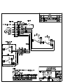
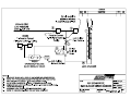
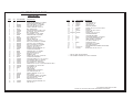
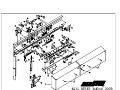
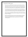
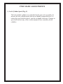
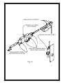
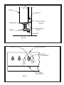
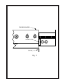
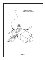
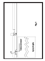
8210 SERIES
SLIDING DOOR OPERATOR
8210 SERIES SLIDING DOOR
PARTS LIST
ITEM
1
1
2
2
3
4
5
6
7
8
9
9
10
11
12
13
13
14
14
15
16
17
18
18
19
20
21
22
23
24
24
25
26
27
28
29
30
31
31
32
33
34
34
35
36
37
38
QTY
1
1
1
1
6
1
4
11
1
11
1
1
1
2
2
1
1
1
1
5
1
1
1
1
1
1
2
1
1
1
1
2*
2*
10
10
6
1
1
1
4
2
1
1
1
1
2*
2*
PART NUMBER
**
**
82008901
82008902
10001301
821016
10006209
10002407
821017
10000706
820085
820225
82004102
10002402
10002303
82004301
82004302
82008705
82008706
10003401
10002802
820021
820223
820080
10000101
100072
10001000
820107
10002503
82019401
82019201
10000707
10001004
10000708
10001408
2NT61
**
**
**
10001302
82009801
820195
820193
820366
**
10002803
10000211
DESCRIPTION
BACKPLATE WELDMENT, L/C (SHOWN)
(OR) BACKPLATE WELDMENT, R/C
ASSY, LIMIT SWITCH, LH (SHOWN)
(OR) ASSY,LIMIT SWITCH, RH
SCREW, CARRIAGE, 1/4-20 X 3/4
ASSY, INSIDE GUIDE
SELF RETAINING NUT, SHORT, 3/8-16
NYLOCK NUT, 1/4-20 ZINC PLATED
ASSY, OUTSIDE GUIDE
FLAT WASHER, 1/4 TYPE 'B' REG
OVERRIDE GUIDE L/C (SHOWN)
(OR) OVERRIDE GUIDE, R/C
ASSY, VALVE, KR
HEX NUT, SEMS, 6-32
SCREW, RH, SLOTTED, 6-32 X 1
ASSY, LOCK CYLINDER, L/C (SHOWN)
(OR) ASSY, LOCK CYLINDER, R/C
ASSY, LOCK SWITCH, L/C (SHOWN)
(OR) ASSY, LOCK SWITCH, R/C
SCREW, TP, BH, 3/8-16 X 1
WASHER, CONICAL SERRATED, 3/8
LOCKBAR SLIDE BRACKET
OVERRIDE CATCH, L/C (SHOWN)
(OR) OVERRIDE CATCH, R/C
PEM STUD, 1/4-20 X 3/4
TERMINAL STRIP
SCREW, HEX HD, 6-20 X 1/2 TYPE 'AB'
LOCKBAR SLIDE BEARING
SHOULDER SCREW, 3/8 X 1-1/2 LG, 5/16-18
LOCK BRACKET, REAR, L/C (SHOWN)
(OR) LOCK BRACKET, REAR, R/C
FLAT WASHER, 5/16, TYPE 'B' REG
SCREW, HHCS, 5/16-18 X 1-1/2, W/NYLON PATCH, GRD 8
FLAT WASHER, 3/8, TYPE B, REG.
LOCK WASHER, 3/8
HEX NUT, 3/8-16
DOOR HANGER
HOUSING COVER, L/C (SHOWN)
(OR) HOUSING COVER, R/C
SCREW, CARRIAGE, 1/2-13 X 1-1/4
ASSY, ROLLER
LOCK BRACKET, FRONT, L/C (SHOWN)
(OR) LOCK BRACKET, FRONT, R/C
PUSH BRACKET, K-R
SWITCH ACTUATOR BRACKET
WASHER, CONICAL, SERRATED, 5/8
HEX NUT, 5/8-11
ITEM
QTY
PART NUMBER
39
4
40
4
41
4
42
2
43
2
44
1
45
6
46
1
47 AS REQ'D
48
1
49
1
50
1
50
1
51
1
51
1
52
1
53
1
53
1
54
1
55
4
56
4
*
**
10001410
10000710
10000210
820501
10001001
820073
10001006
**
10003402
**
**
820170
820181
**
**
820072
**
**
**
216-0072-031
10001002
DESCRIPTION
LOCK WASHER, 1/2
FLAT WASHER, 1/2
HEX NUT, 1/2-13
ASSY, KICK RELEASE
SCREW, HEX, CAP, 3/8-16 X 5/8, GRD 5
SHUTTER
SCREW, HEX, CAP, 3/8-16 X 1
DOOR SKIRT
SCREW, TP, BH, 10-32 X 1/2
LOCKBAR WELDMENT
LOCKTUBE WELDMENT
DOOR GUIDE BRACKET, L/C (SHOWN)
(OR) DOOR GUIDE BRACKET, R/C
JAMB, CHANNEL, L/C (SHOWN)
(OR) JAMB, CHANNEL, R/C
DOOR STOP PLATE
DOOR GUIDE, L/C,(SHOWN)
(OR) DOOR GUIDE, R/C
8200 SERIES WIRING HARNESS (NOT SHOWN)
SPACER
SCREW, HEX, CAP, 3/8-16 X 1-1/4
PART OF ASSY, ROLLER ITEM #33
PART NUMBER ASSIGNED ON A JOB BY JOB BASIS.
8210 SERIES SLIDER PARTS LIST.PM6
Revised 12/31/03 (Removed KR Cylinders, Replaced With Spring Release)
MAINTENANCE
The Airteq 8210 & 8215 Series Pneumatic Door operators require a minimum
amount of maintenance. It is recommended that the following items be checked
once every six months.
1) Lubrication (Fig. A)
The lock mechanism and rack should be well lubricated with Super Lube MultiPurpose Synthetic Lubricant (either spray or grease) OR equivalent. Check to see
that the grease has not dried, caked, or become contaminated with dust or other
debris. If the grease is not in good condition, wipe as much as possible from the
lock mechanism and rack and apply new grease. This also applies to the lock motor
linkage, bellcrank, manual override mechanism and kick release bracket.
The kick and lock cylinder piston rods should be wiped clean and relubricated.
DO NOT use any solvents or penetrating oils on the cylinder rod. Wipe the old
lubricant off with a lint free cloth. Coat the cylinder rod with a thin film of Parker
Luba-A-Cyl, Part #0761630000. DO NOT use WD 40 or similar products as they
will cause cylinder seal failure.
NOTE: Bellcrank and manual override mechanism are not present on the 8210
model.
2) Bottom Guide Wear Pads (Fig. D)
The bottom of the door is held in place with two nylon wear pads. These may wear
with use. Check to see that there is not excessive door movement in and out from
the wall. One sixteenth of an inch movement at the bottom of the door is
acceptable. If there is more play than this, the guides need to be adjusted or
replaced.
To adjust the bottom guide, slightly loosen the two bolts on the bottom side of the
bottom guide mounting bracket. Loosen the bolts just enough to squeeze the
guides tighter to the door guide angle. Be sure to leave enough clearance to allow
for smooth operation.
3) Roller Track
Do not lubricate the roller track.
To maintain smooth and quiet operation, the roller track must be kept free of
any accumulation of dirt, dust, or other debris. If the track does not feel smooth,
wipe it off with a lint free cloth or scouring pad. Do not use steel
wool, sandpaper, or anything that may leave grit or fibers on the track.
4) Rollers
The roller assemblies are factory lubricated and sealed. They do not require
lubrication. If the track is clean and the rollers still do not roll smoothly,
wipe the rollers with a clean lint-free cloth.
MECHANICAL ADJUSTMENTS
1) Lock Position (Fig. C)
The lockbar engages the door at the top and bottom in both the open and closed
positions. The top locking points are adjustable.
While holding the door tight against the receiver column, manually raise and
lower the lockbar. This can be done by moving the horizontal lock slide by
hand.
If the lockbar contacts the rear lock bracket, the bracket should be adjusted.
Loosen the two nuts securing the bracket to the door hanger. Move the bracket
as needed to obtain clearance on both sides of the lockbar. Before tightening
the nuts, make sure the lock bracket is level and that the lockbar extends 1/8"
below the lock bracket. Tighten the nuts securely.
To check and/or adjust the front lock bracket, repeat the above procedure with
the door in the fully open position.
2) Door Height (Fig. D & Fig. E)
Improper door height may result in the door hanger rubbing on the cover, or
the bottom door guide angle rubbing on the top or bottom of the locktube
notch.
There are two height adjustment bolts, one for each side of the door. One
complete turn will move the door up or down 1/16". Turn the bolt clockwise to raise the door and counterclockwise to lower the door. When making
height adjustments, first determine how much change is needed, loosen the
axle nut, turn the adjustment bolt the appropriate amount, then tighten the axle
nut securely and check for proper clearances.
3) Lateral Door Position (Fig. D & Fig. E)
The sliding door should clear the lock tube and the sides of the receiving
pocket by approximately 1/16". If the door rubs on any of these surfaces,
or if the door hanger rubs on the cover, adjustment is required.
a) Top Of Door (Fig. E)
The top of the door can be adjusted at both the front and rear edge of the
door.
Loosen the appropriate axle nut. While holding the nut with the wrench,
turn the axle with a 1/4" Allen wrench. Each complete turn of the axle will
move the door approximately 1/8". Turn the axle clockwise to move the
door away from the wall and counterclockwise to bring the door closer to the
wall. Tighten the axle nuts securely after adjustment.
b) Bottom Of Door (Fig.D)
The bottom of the door is adjusted by moving the bottom door guides.
Loosen the two bolts on the bottom side of the bottom door guide mounting
bracket. While holding the guides against the door guide angle, move the
door and guides to the desired position. Tighten the bolts, check that there
is enough clearance between the guides to prevent binding of the guide angle.
NOTE: The glide lug should rest on the door guide angle during door travel.
If more than 1/8" of the glide lug overhangs the door guide angle,
adjust door position so that the glide lug overhangs by no more than
1/8". (1/16" overhang is nominal condition)
4) Rear Door Stop (Fig. F)
The rear door stop locates the door for the proper locked open position. If the
lockbar does not drop completely and freely in this position, the rear door stop
may need adjustment.
To adjust, loosen the two bolts securing the door stop. Find the point at which
the lockbar drops completely and freely. Slide the stop up against the door
hanger. Check for proper operation, then torque the bolts to 75 ft/lbs.
5) Kick Release Assembly (Fig. B)
The kick release assemblies must be adjusted so that when unlocked, the door
moves approximately 1" to 3" (heavier doors will move less than lighter doors).
The kick release assembly has been factory adjusted to achieve approximately
the desired amount of movement, however some adjustment is usually required.
To adjust the amount of door movement at unlock, loosen the shaft collar set
screw and slide the collar in the desired direction as shown in Fig. B. Tighten the
set screw securely and check for proper door movement. Readjust as required.
NOTE: The kick release shaft must fully and squarely contact the push bracket
on the door hanger. Adjust the push bracket as required and securely fasten push
bracket to door hanger.
NOTE: Increased door movement at unlock will increase the force required to
turn the key for hip high manual release. For models with hip high manual
override, door movement may need to be decreased for ease of manual
override operation.
PNEUMATIC ADJUSTMENTS
1) Lock Cylinder Speed (Fig. G)
The lock and kick cylinders are controlled by the same valve assembly. To
increase the lock cylinder speed, turn the tee-handle counterclockwise. To
reduce the speed (and also noise), turn the tee-handle clockwise. Changes in
speed will not have any affect on the amount of force exerted by the air
cylinders.
ELECTRICAL ADJUSTMENTS
1) Secure/Unsecure Indication
Position indication is controlled by two switches. Both the door position switch
and the lock position switch must be made in order to get a secure indication.
a) Lock position switch (LS1)
The lock position switch is located in front of and near the bottom of
the lock mechanism. When the lock bar is at its lowest point this switch
should be depressed. To adjust this switch, place the door in the closed/
locked position. The lockbar lifting pin should now be at the bottom end
of the Z shaped slot in the horizontal lock slide. Loosen the screws
securing the lock position switch. Lower the switch away from the lifting
pin. Then slowly raise the switch until the contacts close (switch will
click at this point). (See Fig. H)
b) Door position switch (LS2)
The door position switch is located on the actuator near the receiving
column. It should be fully depressed when the door is in the
closed/locked position. Pulling the door against the lockbar (away from
the receiving column) should not release the door position switch.
To adjust this switch, loosen the nut securing the switch mounting bracket
to the actuator. Position the door in the closed/locked position. Hold the
door against the lockbar towards the open position. Position the switch
so that it is fully depressed and tighten the nut.( See Fig. H)
GREASE PIVOT POINTS
GREASE ALL SIDES
OF LOCKBAR
GREASE MOVING PARTS
GREASE SLIDE BEARING,
PIVOT POINT & SLIDE
GREASE BOTH SIDES
AND BOTTOM OF SLIDE
Fig. A
KICK RELEASE BRACKET
MORE DOOR MOVEMENT
AT UNLOCK
MAINTAIN 3/16" MIN.
WHEN SHAFT COLLAR
IS AGAINST BRACKET
AS SHOWN.
LESS DOOR MOVEMENT
AT UNLOCK
COLLAR ADJUSTMENT
KICK RELEASE SHAFT
SHAFT COLLAR
GREASE AREA WHERE
SHAFT CONTACTS BRACKET
TYP. BOTH ENDS
SET SCREW
3.500
NOMINAL POSITION,
ADJUST AS REQUIRED
Fig. B
LOCKBAR
CLEARANCE
ALL SIDES
LOCK BRACKET
Fig. C
DOOR
GLIDE LUG
LOCK TUBE
NOTCH
WEAR PADS
BOTTOM GUIDE
ANGLE
GUIDES
BOLTS
Fig. D
AXLE NUT
DOOR HANGER
IN / OUT
ADJUSTMENT
MOVES
DOOR
AWAY
FROM
YOU
MOVES
DOOR
TOWARD
YOU
UP / DOWN
ADJUSTMENT
Fig. E
DOOR HANGER
DOOR STOP
DOOR
Fig. F
LOCK CYLINDER
SPEED ADJUSTMENT
Fig. G