1
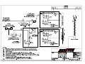
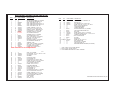
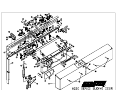
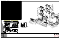
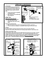
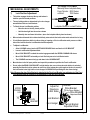
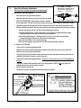
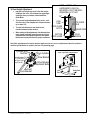
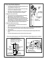
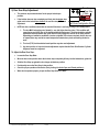
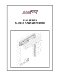
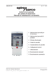
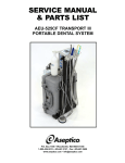
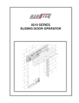
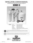
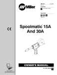
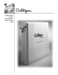
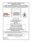
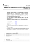
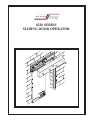
8220 SERIES SLIDING DOOR OPERATOR 8220 SERIES SLIDING DOOR PARTS LIST ITEM 1 1 2 3 4 5 6 7 8 9 10 10 11 11 12 12 13 14 14 15 16 16 17 18 19 20 21 22 23 24 25 26 27 28 29 30 31 31 32 33 34 35 36 37 37 38 39 39 40 41 42 QTY 1 1 1 1 1 1 9 18 1 18 1 1 1 1 1 1 1 1 1 1 1 1 1 6 6 1 2 4 1 2* 2* 1* 1 6 6 2 1 1 5 1 4 4 4 1 1 4 1 1 1 2 4 PART NUMBER DESCRIPTION *** *** 82008903 820090 820395 82008904 10001301 10002407 10002802 10000706 82104801 820085 82104802 820225 820223 820080 82008701 82008702 10000101 *** *** 100072 82004301 82004302 820021 10002303 10002402 820751 82004601 10006209 *** 10000501 10000306 10000401 820072 10001408 10000708 10001001 *** *** 10003401 820218 10001006 10001410 10000710 820195 820193 10001302 82019401 82019201 *** 82009801 10000210 BACKPLATE WELDMENT, L/C (SHOWN) (OR) BACKPLATE WELDMENT, R/C ASSY, LIMIT SWITCH, DBL, LH ASSY, SPEED REDUCING SWITCH, LH ASSY, SPEED REDUCING SWITCH, RH ASSY, LIMIT SWITCH, DBL, RH SCREW, CARRIAGE, 1/4-20 X 3/4 NYLOCK NUT, 1/4-20 ZINC PLATED WASHER, CONICAL, SERRATED, 3/8 FLAT WASHER, 1/4, TYPE B, REG. OVERRIDE GUIDE, L/C (SHOWN) (OR) OVERRIDE GUIDE R/C OVERRIDE CATCH, L/C (SHOWN) (OR) OVERRIDE CATCH, R/C ASSY, LOCK SWITCH, L/C (SHOWN) (OR) ASSY, LOCK SWITCH, R/C PEM STUD, 1/4-20 X 3/4 RECEIVER CHANNEL, L/C (SHOWN) (OR) RECEIVER CHANNEL, R/C TERMINAL STRIP ASSY, LOCK CYLINDER, L/C (SHOWN) (OR) ASSY, LOCK CYLINDER, R/C LOCKBAR SLIDE BRACKET SCREW, RH, SLOTTED, 6-32 X 1 HEX NUT, SEMS, 6-32 ASSY, LOCK CYLINDER VALVE ASSY, DOOR CYLINDER VALVE SELF RETAINING NUT, SHORT, 3/8-16 ASSY, AIR CYLINDER FLAT WASHER, .447 I.D. X .880 O.D. X .030 HEX JAM NUT, 7/16-20 GROMMET DOOR STOP PLATE LOCK WASHER, 3/8 FLAT WASHER, 3/8, TYPE B, REG. SCREW, HEX, CAP, 3/8-16 X 5/8, GRD 5 HOUSING COVER, L/C (SHOWN) (OR) HOUSING COVER, R/C SCREW, TP, BH, 3/8-16 X 1 DOOR DRIVE BRACKET SCREW, HEX, CAP, 3/8-16 X 1 LOCK WASHER, 1/2 FLAT WASHER, 1/2 LOCK BRACKET, FRONT, L/C (SHOWN) (OR) LOCK BRACKET, FRONT, R/C SCREW, CARRIAGE, 1/2-13 X 1-1/4 LOCK BRACKET, REAR, L/C (SHOWN) OR) LOCK BRACKET, REAR, R/C DOOR HANGER ASSY, ROLLER HEX NUT, 1/2-13 See 820080FD for components ITEM QTY PART NUMBER 43 2** 10002803 44 2** 10000211 45 2** 10000707 46 2** 10001004 47 1 *** 48 1 *** 49 1 *** 50 1 820170 50 1 820181 51 1 820108 52 2 10001000 53 1 10002503 54 1 820107 55 1 821017 1 820073 56 57 1 *** 58 AS REQ'D 10003402 59 1 821016 60 1 *** 60 1 *** 61 1 *** DESCRIPTION WASHER, CONICAL, SERRATED, 5/8 HEX NUT, 5/8-11 FLAT WASHER, 5/16, TYPE B, REG. SCREW, HEX, CAP, 5/16-18 X 1-1/2, GRD 5 SWITCH ACTUATOR BRACKET LOCKTUBE WELDMENT LOCKBAR WELDMENT DOOR GUIDE BRACKET, L/C (SHOWN) (OR) DOOR GUIDE BRACKET, R/C NUT PLATE SCREW, HEX HD, 6-20 X 1/2, TYPE AB SHOULDER SCREW, 3/8 DIA X 1-1/2 LG, 5/16-18 LOCKBAR SLIDE BEARING ASSY, OUTSIDE GUIDE SHUTTER DOOR SKIRT SCREW, TP, BH, 10-32 X 1/2 ASSY, INSIDE GUIDE DOOR GUIDE, L/C (SHOWN) (OR) DOOR GUIDE, R/C 8200 SERIES WIRING HARNESS (NOT SHOWN) * PART OF ASSY, AIR CYLINDER ITEM #23 ** PART OF ASSY, ROLLER ITEM #41 *** PART NUMBER ASSIGNED ON A JOB BY JOB BASIS 8220 SERIES SLIDING DOOR PARTS LIST.pm6 ITEM NO. 1 1.1 1.2 1.3 2 3 4 5 6 7 8 9 10 11 12 13 14 14.1 14.2 14.2.1 14.2.2 14.2.3 14.2.4 14.2.5 15 15.1 15.2 15.2.1 15.2.2 15.2.3 15.2.4 15.2.5 16 16.1 16.2 16.2.1 16.2.2 16.2.3 16.2.4 16.2.5 17 17.1 17.2 17.3 17.4 18 18.1 18.2 18.3 19 PART NUMBER 4407-004 4407-001 01-0231 01-0260 4407-002 4407-003 04-01-010 01-0191 01-0004 01-0230 02-1212 02-1213 02-1217 02-1218 02-1211 4407-005 03-4228-001 03-4230-024-3L 03-4231-001 03-4229-001 03-4230-024-3L 03-4232-001 03-4229-002 03-4230-024-3L 03-4232-002 02-1219 02-1215 02-1216 02-1214 4407-007 02-1210 4407-006 DESCRIPTION MANIFOLD BODY, COMPLETE MANIFOLD BODY, MACH BALL, STEEL, 3/16 BALL, METAL, .250" DIA NEEDLE, VALVE NEEDLE VALVE BLOCK O-RING, BUNA, .239 ID X .070CS, #010 WASHER, LOCK, STEEL, #8 SCREW, SHC, #8 X .0625, BLOX NUT, HEX, 1/4-28 FITTING, METAL, 1/4 TUBE - 1/8 NPT FITTING, PLASTIC, SPEED CON. MUFFLER FITTING, PLASTIC, ELBOW, 1/8 NPT - 1/4 TUBE FITTING, ELBOW, PLASTIC, 3/8 TUBE - 1/4 NPT GAGE, 0-60, 1" BACK MOUNT, 1/8 NPT FITTING, MUFFLER, SINTERED BRONZE, 1/8 NPT SOL.ARM. ASSY W/COIL, GKR, 1.5mm, COMPLETE COIL, IND FORM B, 24 VDC SOL.ARM.ASSY.COMPLETE, GKR, 1.5mm ARM. ASSY, GKR,1.5mm GASKET, GKR O-RING, GKR SCREW, MOUNTING, GKR NUT, COIL RETAINING, OPEN SOL.ARM. ASSY, W/COIL, KR, 1.5mm, COMPLETE COIL, IND FORM B, 24 VDC SOL.ARM.ASSY COMPLETE, KR, 1.5mm ARM. ASSY, KR SCREW, ARM, MTG O-RING, LG, KR O-RING, SM, KR NUT, COIL RETAINING, OPEN SOL.ARM. ASSY, W/COIL, KR, 1mm, COMPLETE COIL, IND FORM B, 24 VDC SOL.ARM.ASSY COMPLETE, KR, 1.0mm ARM. ASSY, KR SCREW, ARM, MTG O-RING, LG, KR O-RING, SM, KR NUT, COIL RETAINING, OPEN QUICK EXHAUST VALVE ASSY. FITTING,TEE, PLASTIC, 1/4 TUBE - 10-32 QUICK EXHAUST VALVE,10-32 MUFFLER, 10-32 GASKET, RUBBER REGULATOR ASSY, COMPLETE REGULATOR, 1/2-13 O-RING, LG O-RING, SM LABEL QTY. 1 1 12 1 1 1 1 2 2 1 2 2 1 1 1 1 2 1 1 1 1 1 4 1 2 1 1 1 2 1 1 1 1 1 1 1 2 1 1 1 1 1 1 1 1 1 1 1 1 1 D4407-601 15.2.5 15.1 15.2.2 14.2.5 15.2.1 14.1 15.2.3 14.2.4 15.2.4 14.2.1 14.2.2 17.3 17.2 14.2.3 17.1 13 1.1 18.1 17.4 18.2 18.3 16.2.5 16.1 16.2.2 9.07 7.75 .25 .25 1.07 16.2.1 7.25 8 9 16.2.3 9 8 1.2 12 7 16.2.4 3.50 6 1.2 5 3 2 1.2 10 4 1.2 11 1.3 1.2 9.20 19 F Tolerances Unless Otherwise Specified: TYPE DEC .00 DEC .000 FRACTIONAL ANGLES FINISHED MATERIAL SPEC. PC. NO.: AS CAST .015" .005" 1/64" 1/2 .030" .010" 1/32" 1 8200FD JAIL DOOR MANIFOLD 8220/8250 SeriesLIST Manifold Assy CUSTOMER PARTS Airteq Systems 3224 Mobile Hwy Montgomery, AL 36108 2025 Mercer RD, Lexington, Kentucky DRAWN 40511 4407-601 MADE FROM: PROCESS SPEC. FINISH 175 µ in. ECL: UPDATED DESCRIPTIONS FOR ITEMS 8, 17, & 17.2 ECL 09026 03-31-09 MDL UPDATED DESCRIPTIONS FOR ITEMS 15 , 16 AND REMOVED ITEM 17.5 ECL 10061 09/24/10 TPO D ECL08158 10-06-08 MJM ADDED P/N 17.4 TO ASSY C ECL08126 08/28/08 TPO ADDED LABEL, ITEM # 19 B ECL08084 05/30/08 TPO ITEM 11 DESCRIPTION CHANGED AS WELL AS OVERALL LENGTH A REVISIONS 3.74 1.2 ASSY CHECKED MODEL FILE: 4407-601.SLDASM CAD FILE: 4407-601.slddrw D 4407-601 APRVD. TPO TPO 01/17/08 01/17/08 SHEET NO. 1 of 1 SCALE 3:4 APPROX. WT. SHEETS LUBRICATION, MAINTENANCE & ADJUSTMENTS 8220 & 8250 SLIDING DOORS 3224 Mobile Highway Road ● Montgomery, Alabama 36108 (334)281-8440 ● FAX (334)286-4320 Lubrication and Adjustments – 8220/8250 3/2009 1 LUBRICATION and MAINTENANCE 1) Lubrication: The lock plate mechanism, bell crank and manual override mechanism should be well lubricated, in the areas shown, with Super Lube ® Multi-Purpose synthetic lubricant grease. Check for dried, caked or dust/debris contaminated grease. Wipe off grease in poor condition and apply new grease GREASE PIVOT POINTS GREASE LOCK PLATE (SIDES, BOTTOM & SLOT) GREASE ALL SIDES OF LOCKBAR GREASE OVERRIDE MOVING PARTS GREASE SLIDE BEARING (INSIDE & OUT) OVERRIDE LINKAGE SLOT & LOCKBAR ASSIST SPRING 2) Roller Track DO NOT lubricate the roller track. To maintain smooth and quiet operation: Keep roller track free of any accumulation of dirt, dust, or other debris. If the track does not feel smooth: Wipe track off with a lint free cloth or scouring pad (Scotch Brite® or equivalent.) Do not use steel wool, sandpaper, or anything that may leave grit or fibers on the track. 3) Rollers The roller assemblies are factory lubricated and sealed. They do not require lubrication. If the track is clean and the rollers still do not roll smoothly, wipe rollers with a clean lint free cloth. 4) Bottom Guide Wear Pads The door bottom is held in place by two Door Guide plates (each having a nylon wear pad.) Check for excessive door movement in and out from the wall. 1/16th” movement at the bottom of the door is acceptable. More than 1/16th” movement requires that the guides be adjusted and/or the wear pads be replaced. Bottom Door Guide adjustment is detailed in the Mechanical Adjustments section, under number 4 part b: “To Adjust Door Bottom Lateral Position.” NOTE: A DOOR WITH A HARDWARE FLUSH PULL MOUNTED LOCK TUBE SIDE REQUIRES A 3/16” GAP DOOR DOOR GUIDE WEAR PADS DOOR GUIDE ANGLE 1/8" BOTTOM DOOR GUIDE INSIDE DOOR GUIDE OUTSIDE DOOR GUIDE LOCK TUBE DOOR GUIDE NOTCH WASHER BRACKET LOCK WASHER BOTTOM DOOR GUIDE ADJUSTMENT BOLTS Lubrication and Adjustments – 8220/8250 3/2009 DOOR DOOR GUIDE ANGLE WEAR PADS DOOR GUIDES 2 TO RAISE LOCKBAR Manually Move Lockplate Away From Cylinder: 8200 Series or Motor: 7200 Series MECHANICAL ADJUSTMENTS 1) Lock Position Adjustment The lockbar engages the door at the top and bottom in both the open and closed positions. The top locking points are determined by the door hanger mounted front and rear Lock Brackets. To Check the rear Lock Bracket position: Lockplate Shown In Locked Position o Move the door to the fully closed position o Hold the door tight into the receiver column o Manually raise and lower the lockbar. (move the Lockplate slide by hand as shown.) When raised and lowered the Lockbar should freely enter and exit the lock bracket notch and not bind or hang If Lock Bracket interferes with the Lockbar raising or lowering or if the Lock Bracket notch presses on either side of the Lock Bar then the Lock Bracket should be adjusted. To Adjust Lock Bracket: o Allow LOCKBAR to drop into the BOTTOM DOOR GUIDE Notch and into the LOCK BRACKET o Loosen Lock Bracket Adjustment Nuts o Move LOCK BRACKET to obtain the vertical engagement with the UPPER LOCKBAR LUG shown o Move LOCK BRACKET horizontally so Lock Bar freely moves in Lock Bracket notch. o The LOCKBAR must move freely up and down in the LOCK BRACKET Move the door to the full open position and repeat this procedure to position the Front Lock Bracket Do not adjust the REAR LOCK BRACKET so high that the door can not close when the lockbar is unlocked manually and then the lock bar release to rest on top of the bottom door guide angle as the door is moved (if the lock bracket is too high it will run into the upper LOCKBAR LUG preventing the door from closing.) Note: Because the door Drive Bracket is attached to the Front Lock Bracket, any adjustment of the Front Lock Bracket must be followed by an adjustment of the door drive bracket. Adjust for Clearance On Slot Sides UPPER LOCKBAR LUG Lock Bar Drive Bracket (Fully Driven Models) Drive Bracket Adjustment Bolts ⅛” Lubrication and Adjustments – 8220/8250 Lock Bracket LOCK BRACKET Door Hanger 3/2009 Lock Bracket Adjustment Nuts 3 TO RAISE LOCKBAR 2) Door Drive Bracket Adjustment The Door Drive Cylinder rod must not be side loaded. One test for a side load condition: Manually Move Lockplate Away From Cylinder: 8200 Series or Motor: 7200 Series o Move the door to the open/locked position. o Manually unlock the door by moving the Lock Plate as shown. o Lockplate Shown In Locked Position With the LOCKBAR lifted, manually move the door towards the closed position. The door should move easily and may even start to move by itself, this is normal. o Approaching the fully open position, the effort required to move the door should not increase at all. o Possible conditions present if door movement becomes restricted approaching the fully open position: Severely side loaded cylinder rod (Drive Bracket Adjustment required) Vertically misaligned door - either rubbing the cover or bottom door guide slot (Door Height Adjustment required, followed by a Drive Bracket Adjustment) Horizontally misaligned door – Robbing the lock column or cover (Door Lateral Position Adjustment required, followed by a Drive Bracket Adjustment) Dirty roller track (Roller Track requires cleaning) Door Skirt is dragging a high spot in the floor (Door Skirt Adjustment required) To Adjust the Drive Bracket: o Loosen the Drive Bracket Adjustment Bolts o Slightly loosen Cylinder Rod End Nut (allows cylinder rod to slide freely in the drive bracket slot). o Move the door to the open/locked position. o Typically the cylinder will push the bracket out to the end of the slot. Move bracket by hand in & out and back & forth until the bracket / cylinder feels ‘free.’ o Secure the Drive Bracket Adjustment Bolts - ensure the drive bracket does not move while tightening the bolts. o Tighten the Cylinder Rod Nut with the door in the open position. NOTE: Do not over tighten the cylinder rod nut and crush the rubber grommet! o DO NOT bind the cylinder rod o Verify proper cylinder rod alignment (No Side Loading on Cylinder) Cylinder Rod End Nut After Adjustment DO NOT Crush Grommet When Tightening End Nut Drive Cylinder Drive Bracket Drive Bracket Adjustment Bolts Front Lock Bracket Lubrication and Adjustments – 8220/8250 3/2009 4 3) Door Height Adjustment Improper door height may result in the door hanger rubbing on the cover, or the bottom door guide angle rubbing on the top or bottom of the bottom Door Guide Notch. NOTE: A DOOR WITH A HARDWARE FLUSH PULL MOUNTED LOCK TUBE SIDE REQUIRES A 3/16” GAP 1/8" There are two height adjustment bolts, one for each side of the door. One complete turn will move the door up or down 1/16". Turn the bolt clockwise to raise the door and counterclockwise to lower the door. DOOR GUIDE NOTCH When making height adjustments, first determine how much change is needed, loosen the axle nut, turn the adjustment bolt the appropriate amount, then tighten the axle nut securely and check for proper clearances. BOTTOM DOOR GUIDE LOCK TUBE DOOR DOOR GUIDE ANGLE WEAR PADS DOOR GUIDES Note: After any adjustment is made to the door height or the door in or out, re-adjustment of the drive cylinder to the drive cylinder bracket is required. (See Item 2 on preceding page) Cylinder Rod End Nut After Adjustment DO NOT Crush Grommet When Tightening End Nut Drive Cylinder Drive Bracket Drive Bracket Adjustment Bolts Front Lock Bracket Lubrication and Adjustments – 8220/8250 Door Up/Down Adjustment 1/2" Wrench Lower Door 3/2009 Raise Door 5 4) Door Lateral Position Adjustment The sliding door should clear the lock tube and the sides of the receiving pocket by a minimum of 1/16" If the door rubs on any of these surfaces, or if the door hanger rubs on the cover, adjustment is required. Note: After any door position adjustment is made. The Door Drive Bracket / Cylinder Alignment must be re-adjusted. a) To Adjust Door Top Lateral Position: The top of the door can be adjusted at both the front and rear edge of the door. Loosen the appropriate axle nut. While holding the nut with a wrench, turn the axle with a 1/4" Allen wrench. Each complete turn of the axle will move the door approximately 1/8". Turn the axle clockwise to move the door away from the wall and counterclockwise to bring the door closer to the wall. Tighten the axle nuts securely after adjustment. b) To Adjust Door Bottom Lateral Position Loosen the two bolts on the bottom side of the bottom door guide mounting bracket. While holding the guides against the door guide angle, move the door and guides to the desired position. (a 1/16” shim may be used to help space guides and Bottom Guide Angle properly) Tighten the bolts Check that the bottom door guide angle travels smoothly through the guides throughout limits of door travel Check door Gap throughout travel (Lock column, wall and receiver pocket After any door position adjustment is made. The Door Drive Bracket / Cylinder Alignment must be re-adjusted. NOTE: A DOOR WITH A HARDWARE FLUSH PULL MOUNTED LOCK TUBE SIDE REQUIRES A 3/16” GAP 1/8" LOCK TUBE DOOR GUIDE NOTCH BOTTOM DOOR GUIDE Lubrication and Adjustments – 8220/8250 Door In/Out Adjustment Move Door Out 15/16" Wrench DOOR DOOR GUIDE ANGLE WEAR PADS Axle Nut Roller Axle Wrench to Prevent Axle Nut From Turning During In/Out Adjustments Move Door In 1/4" T-Handle Allen Wrench DOOR GUIDES 3/2009 6 Door Hanger Door Stop Bolts 5) Rear Door Stop Adjustment The rear door stop locates the door for the proper locked open position. If the lock bar does not drop completely and freely into the bottom door guide notch in the locked open position, the rear door stop MAY need adjustment NOTE two other conditions should also be checked if the door is not freely locking in the OPEN position: Door Stop Left Close Configuration Shown 1. The door MAY be hanging out of plumb (i.e. one side higher than the other). This condition will cause the top end of the door to be misaligned with the bottom end. The door should be vertically adjusted to allow the bottom door guide notch to freely engage the lock bar in the open position. Depending on installation conditions (receiver not plumb, lock column not plumb, and/or door out of square) there may need to be some compromise between door plumb and making the device work. 2. The front (TOP) lock bracket horizontal position may also need adjustment 3. Any door position or front lock bracket adjustment requires that the Door Drive Bracket / Cylinder Alignment must be re-adjusted To Adjust the Rear Door Stop: Loosen the Door Stop Bolts. Move the door to the position where the lock bar drops completely & freely into the bottom door guide slot. Slide the Door Stop up against the door hanger at that door position. Provisionally secure the Door Stop in that position Check for proper operation of the device (freely locking in both the Open and Closed positions.) When device operates properly, torque the Door Stop Bolts to 75 ft/lbs. Lubrication and Adjustments – 8220/8250 3/2009 7 Door Open Deceleration Adjustment (CW Slower, CCW Faster) PNEUMATIC ADJUSTMENTS 1) Drive Cylinder Pressure: The drive cylinder pressure is adjusted by a pressure regulator. Increasing drive cylinder pressure will increase the door’s travel speed. Lock Cylinder Unlock Speed Control (CW Slower CCW Faster) Door Close Deceleration Adjustment (CW Slower, CCW Faster) Drive Cylinder Rear Air Connection Drive Cyl. Nose Air Connection To increase Drive Cylinder Pressure: o Turn Pressure Adjustment knob clockwise Drive Cylinder To decrease Drive Cylinder Pressure: Pressure Gauge Lock Cylinder o Turn Pressure Adjustment knob: Air Connection Counterclockwise below desired pressure Clockwise up to desired pressure. Main Air Supply Drive Cylinder Connection Cylinder drive force is gauge pressure shown Pressure Adjustment RMERS (CW Increase, CCW Decrease) Air Connection multiplied by 1.23: (i.e. 32.5 psig x 1.23 =40 lbs) NOTE: Dirt particles in the air stream may lodge under the pressure regulator diaphragm during door operation. This condition can result in a constant air "bleed off" that is usually clearly audible. To correct this problem: o Turn off the air supply to the door. o Disassemble, clean and re-assemble the pressure regulator o The pressure regulator body does not need to be removed from the valve manifold. o Check main air system particle filter element(s) at the compressor location A dirty filter element can permit dirt particles into the line air stream. o Turn on air supply to the door 2) Lock Cylinder Unlock Speed (Lock bar Unlocking Speed & Noise-“Bang”): To increase the lock cylinder speed (and raise Lock Bar Unlocking noise/bang): o Loosen the LOCK CYLINDER UNLOCK SPEED CONTROL jamb nut o Turn the LOCK CYLINDER UNLOCK SPEED CONTROL adjustment screw OUT (counter clockwise) slightly o Secure the LOCK CYLINDER UNLOCK SPEED CONTROL jamb nut To decrease the lock cylinder speed (and reduce Lock Bar Unlocking noise/bang) o Loosen the LOCK CYLINDER UNLOCK SPEED CONTROL jamb nut o Turn the LOCK CYLINDER UNLOCK SPEED CONTROL adjustment screw IN (clockwise) slightly o Secure the LOCK CYLINDER UNLOCK SPEED CONTROL jamb nut Changes done with the LOCK CYLINDER UNLOCK SPEED CONTROL do not affect the unlocking force exerted by the lock cylinder on the lock bar. The LOCK CYLINDER UNLOCK SPEED CONTROL does affect the speed and the corresponding momentum of the lock bar as it raises. The Lock Cylinder Speed should be adjusted until the lock bar can be clearly heard when unlocking but no more. Allowing the lock bar to unlock at maximum speed (and noise) puts excessive strain on the lock bar roller bearing shoulder bolt and should be avoided. 3) Door Deceleration Control The deceleration controls slow the door down a few inches prior to end of travel for smooth, consistent locking in the open and closed positions. If a door impacts the receiving column or rear door stop too hard or travels too slowly in the last few inches of travel, the deceleration control for the door direction in question (Open or Close) must be adjusted: To reduce the end of travel speed (to correct door ramming the receiving column or rear door stop): o Turn the associated direction’s Deceleration Adjustment knob clockwise. To increase the end of travel speed (to correct door traveling too slowly in the deceleration range): o Turn the associated direction’s Deceleration Adjustment knob counter clockwise. Note: If a door “bounces” – (briefly reverses direction) when a deceleration switch is initially contacted: o Drive cylinder pressure is likely adjusted too high: Decrease drive cylinder pressure (step 1 above) o Adjust Deceleration Control for appropriate door deceleration speed Lubrication and Adjustments – 8220/8250 3/2009 8 ELECTRICAL ADJUSTMENTS LS4A & LS4B 1) Secure/Unsecure Indication Device Status indication is controlled by the Lock Bar Down Status Switches (LS2A & LS2B) and the Door Position Switches, Door Closed Status (LS4A & LS4B) and Door Open Status Switches (LS3A & LS3B). Both the Door Closed Status Switch (LS4B) and the Lock Bar Down Status Switch (LS2A) must be made in order to generate a secure indication. If either switch is not made, an insecure indication is provided. LS1A & LS1B LS5 LS6 LS3A & LS3B LS2A & LS2B SWITCH ACTUATOR BRACKET LEFT CLOSE DOOR (Shown Closed) 8200 Series Switch Locations a) Lock Bar Down Status Switches (LS2A & LS2B) The Lock Bar Down Status Switches are located in front and near the bottom of the lock mechanism. Only when the lock bar is at its lowest point should these switches be depressed. To adjust the Lock Bar Down Status Switch Position: Place the door in the closed/locked position. The lock bar lifting pin should be at the bottom end of the Z shaped slot in the horizontal lock slide. Slots are provided in the mounting bracket for adjustment. Loosen the screws securing the Lock Bar Down Status Switches. Lower the switches away from the lifting pin. Then slowly raise the switches until the contacts close (switches will click at this point). Secure the screws attaching the Lock Bar Down Status Switches. b) Door Closed Position Status Switches (LS4A & LS4B) These Door Closed Position Status Switches are ganged together on a bracket mounted to the device tray near the receiving column/channel. These Status Switches signal the lock bar to drop when the door reaches the fully closed position. They should be fully depressed by the SWITCH ACTUATOR BRACKET when the door is in the closed/locked position. Pulling the door against the Lock bar (away from the receiving column/channel) should not release either of these Door Closed Position Status Switches. To adjust the Door Position Status Switch: Loosen the switch bracket mounting nut that secures switch bracket to the device tray. Position the door in the closed/locked position. Hold the door tightly against the lock bar towards the open position. Position the switches so that they are fully depressed (switch arms fully activated) Switch Bracket should not at an angle, both switches should make at the same time Tighten the switch bracket mounting nut. 2) Lock Bar Unlocked Status Switches (LS1A & LS1B) The Lock Bar Unlocked Status Switch engages the door drive cylinder after the lock bar is fully raised when the control panel has provided a door open or door close signal. These switches are located in front of and near the top of the lock mechanism. These Status Switches should be depressed when the lock bar is at the top of its travel. To adjust the Lock Bar Up Status Switch Position: Loosen the screws securing the Lock Bar Up Status Switches. Manually pull the horizontal lock plate to the fully unlocked position, lock bar fully raised Slots are provided in the mounting bracket for adjustment. Raise the switches away from the lifting pin. Then slowly lower the switches until the contacts close (switches will click at this point). Secure the screws attaching the Lock Bar Up Status Switches. Lubrication and Adjustments – 8220/8250 3/2009 9 3) Fully Open Switches (LS3A & LS3B) These Door Fully Open Position Status Switches are ganged together on a bracket mounted to the device tray near the rear door stop of the device. These Status Switches signal the lock bar to drop when the door reaches the fully open position. They should be fully depressed by the SWITCH ACTUATOR BRACKET when the door is in the fully open/locked position. To adjust the Door Position Status Switch: Loosen the switch bracket mounting nut that secures switch bracket to the device tray. Position the door in the opened/locked position. Hold the door tightly against the lock bar towards the closed position. Position the switches so that they are fully depressed (switch arms fully activated) Switch Bracket should not at an angle, both switches should make at the same time Tighten the switch bracket mounting nut. 4) Deceleration Switches (LS5 & LS6) There are two deceleration switches: LS5 signals open deceleration and LS6 controls signals close deceleration. The open deceleration switch (LS5) is located above and near the center of the door when the door is in the open position. The close deceleration switch (LS6) is located above and near the center of the door when the door is in the closed position. The deceleration switches deactivate a solenoid valve, which slows down the door travel speed toward the end of the door’s range of motion. These switches are adjusted in conjunction with the door deceleration flow control valves. If the door impacts the receiving column or rear door stop too hard, or if the door moves too slowly at the end of its travel, first refer to "Door Deceleration Control" in Pneumatic Adjustment section. If proper deceleration cannot be achieved pneumatically, adjust the position of the deceleration switch. The position of the deceleration switch determines the point at which the door begins to slow. To adjust a deceleration switch position: Loosen the switch bracket mounting nut that secures the deceleration switch bracket to the device tray. Slide the bracket to the desired position in device tray mounting slot and tighten the nut. o Moving the switch towards the center of the device will cause the door to decelerate sooner. o Increasing the deceleration length will increase the time it takes to open or close the door. o Decreasing the deceleration length too much can result in the door "bouncing" at the end of its travel or impacting the receiving column or rear door stop too severely. Check that the Deceleration switch arm is riding smoothly onto the SWITCH ACTUATOR BRACKET and is not interfering with any door or roller hardware. If interference is detected adjust the switch position to remove the interference. Lubrication and Adjustments – 8220/8250 3/2009 10