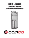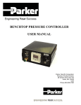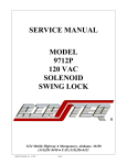
1
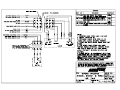
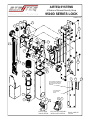
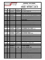
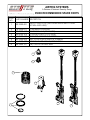
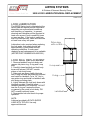
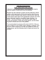
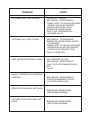
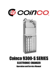
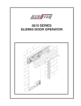
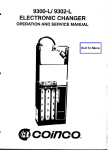
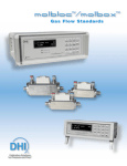
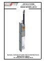
AIRTEQ SYSTEMS
A Division of Norment Security Group
9500D SERIES LOCK
9500D 4-28-06
Remote controlled 2" jamb internal latchbolt lock.
Mortise key release
For swing door or sliding doors
AIRTEQ SYSTEMS
A Division of Norment Security Group
9500D SERIES LOCK
9500D2-13-07
6
4
21
5
5
20
19
7
22
18
8
9
17
10
13
12
2
11
16
14
39
41
42
43
44
37
36
22
27
25
26
23
24
28
35
29
34
34
25
PLACE STATUS SWITCH
ACTUATOR IN PISTON
RING NOTCH IN BOLT
GROVE
PLACE RACK
IN SLOT IN
BOLT
32
31
8
RACK/GEAR
TIMING DETAIL
12
9
17
KEY SWITCH ASSEMBLY
INSTALLATION DETAIL
RACK AND LSS
DETAIL
17
AIRTEQ SYSTEMS
A Division of Norment Security Group
9500D SERIES LOCK
ITEM
NO.
QTY
1
1
2
3
4
1
2
1
146-9400-102
146-9400-101
340-0000-205
146-9400-113
330-0000-414
5
2
330-0000-133
6
7
8
9
10
11
12
13
14
15
16
17
1
2
1
1
1
2
1
1
2
1
1
1
18
1
19
20
2
4
21
1
22
23
24
25
26
27
28
29
6
4
3
1
1
3
1
1
30
1
31
32
33
1
1
1
34
1
35
36
37
38
39
40
41
42
43
44
45
1
1
1
1
3
1
1
1
1
3
1
331-0000-053
310-0632-006
216-9400-248
216-9400-241
216-9400-284
313-0000-072
216-9400-285
330-1206-000
310-0256-000
160-9500-005
216-9500-122
216-9500-130
216-9524-006
146-9500-135
216-9500-091
310-0832-015
310-0832-026
216-9500-023
216-9500-101
216-9500-067
311-0632-018
310-2520-019
310-0632-010
216-9500-142
216-9400-247
313-0000-088
330-0000-086
216-9500-119
146-9500-086
146-9500-087
313-0000-050
313-0000-116
146-9500-132
216-9500-120
146-9500-134
313-0000-052
216-9524-011
330-1206-000
146-9400-098
319-0000-044
146-9400-097
216-9400-256
146-9400-099
319-0000-045
310-1032-003
330-0000-415
PART NUMBER
REQ. FOR
FEATURE:
KEY SWITCH
STANDARD
DESCRIPTION
9500D 5/1/06
CIRCUIT BOARD ASSY W/KEY SWITCH (SHOWN)
(OR) CIRCUIT BOARD ASSY
5" SPLIT CONVOLUTED TUBING, .343, BLK
BAYONET LUG ASSY
COUPLING HALF (LOCK SIDE)
FITTING, 10-32 X .078 90 BARB PNEUTRONICS #190-8035
SOLENOID D SERIES
SCREW, SHCS 6-32 X .250 BLACK
MORTISE CYLINDER PLATE R.H.
GEAR SUPPORT PLATE
Air Line Spacer
WASHER, PLASTIC
GEAR SUPPORT PLATE
TUBING, 1/8 ODX 1/6 ID POLYURETHANE
SCREW, SHCS 2-56 X .500 BLACK
ASSY, LOCK STATUS SWITCH, D SERIES
SPACER, LOCK STATUS SWITCH
RACK, 95D
STANDARD
MOUNTING PLATE "D" SERIES (SHOWN)
GRADE 1
(OR) MOUNTING PLATE, GRADE 1
SLIDING DOOR (OR) MOUNTING PLATE, SLIDING DOOR
SET SCREW, 8-32 X .438
SCREW, 8-32 X .375 FH BLACK
STANDARD
FACEPLATE (SHOWN)
GRADE 1
(OR) FACEPLATE, GRADE 1
SLIDING DOOR (OR) FACEPLATE, SLIDING DOOR
QTY. 8 GRADE 1 SCREW, TORX,6-32X3/16, UNDCUT HD SST
SCREW, FH SOCKET 1/4-20 X .500
SCREW, SHCS 6-32 X 1
STATUS SWITCH ACTUATOR
MORTISE CYLINDER PLATE
LOCKWASHER #6
FITTING, 10-32 X 1/16 BARB
TOP COVER
STANDARD
LOCK BODY ASSEMBLY (SHOWN)
SLIDING DOOR (OR) LOCK BODY, SLIDING DOOR
O-RING, 2-016 VITON, 70D
SEAL, U-CUP, PARKER #8504-0100-4180 BONAN
TOP COVER ASSEMBLY
STANDARD
LATCHBOLT (SHOWN)
ELHB
(OR) ASSY, LATCHBOLT ELHB
PISTON RING, 1.25 X .070 DYNAMIC SEALS TFE-S-4
COMPRESSION SPRING
TUBING, 1/8 ODX 1/16 ID, POLYURETHANE, 8"
KEY SWITCH KEY SWITCH ASSY D SERIES
SPACER, 1/4 X 3/8
GEAR ASSY, D SERIES
SPACER .250 X .438 DIA
KLHB & ELHB ASSEMBLY, KLBH
SPACER 1/4 X 1/4
SCREW, SHCS 10-32 X .375 BLACK
COUPLING HALF (FIELD SIDE)
AIRTEQ SYSTEMS
A Division of Norment Security Group
9500D RECOMMENDED SPARE PARTS
ITEM PART NUMBER DESCRIPTION
NO.
9500D 5-1-06
1
KIT 9500 LOCK (INCLUDES SEALS AND O RING
400-9500-001 SEAL
SHOWN AND LUBE)
2
3
4
5
6
7
8
216-9524-011
330-0000-415
330-0000-414
146-9400-110
160-9500-005
146-9400-102
146-9400-101
COMPRESSION SPRING
COUPLING HALF (FIELD SIDE)
COUPLING HALF (LOCK SIDE)
SOLENOID ASSEMBLY D SERIES
ASSY, LOCK STATUS SWITCH, D SERIES
CIRCUIT BOARD ASSY W/KEY SWITCH
(OR) CIRCUIT BOARD ASSY
3
4
2
5
1
8
7
AIRTEQ SYSTEMS
A Division of Norment Security Group
9500 LOCK LUBRICATION/SEAL REPLACEMENT
9500D 5-2-06
LOCK LUBRICATION
The 9500D Series Lock is lubricated at the
factory and will require periodic lubrication
depending on environmental conditions
and frequency of operation. In general,
cleaning and lubrication will be required at
least once a year if lock is used fifty times
or more per day. If the locks is used less
than fifty times per day, clean and lubricate
at least once every two years.
Lubrication is also required when replacing
the lock seals. Lock seals should last
approximately 5 years under normal
operating conditions. If seals need
replacing a seal replacement kit is available
(AIRTEQ PART NUMBER 400-9500-001).
Piston ring
with cut slot
LOCK SEAL REPLACEMENT
1. Remove latchbolt from lock body and
remove old piston ring, O-ring and u-cup
seal.
2. Carefully clean latchbolt and lock body
bores with solvent. DO NOT scratch
piston or lock body bores.
3. After parts are clean, lightly lubricate
new O-ring and seal with lubricant provided
and install on latchbolt. Cut a 1/4" slot in
new piston ring and install on latchbolt with
slot facing mounting plate.
4. Lightly lubricate the lock body bores with
lubricant provided. Carefully insert
latchbolt assembly into lock body. DO NOT
tear the O-ring as it enters the bores
or passes by the notch in lock body. DO
NOT scratch lock body bores.
5. Reassemble lock and check for proper
operation.
NOTE:
Lubricant provided is SYNCO SUPER
LUBE WITH TEFLON. Use only
approved lubricant.
U-cup seal
O-ring
Latchbolt
LOCK MAINTENANCE INFORMATION
PNEUMATIC LOCKING DEVICES
A. Lubrication and cleaning
1. Each Airlock is well lubricated at the time of assembly. However,
all lubricants deteriorate eventually and need replacing on a
regularly scheduled basis in order to prevent equipment failure.
Airteq Systems recommends cleaning and lubricating each type
of lock according to the following instructions approximately
every (2) years. (Yearly for locks in high use areas).
9400 SERIES LOCK:
Remove the side cover plate and lubricate the angled ramp surface
on the sideplate that the deadlatch bolt dowel pin rides against.
Lubricate the stop side of the deadlatch bolt (back side). When
replacing the side cover, be sure the lever of the lock status switch
is not trapped under the retainer plate or actuator. The lower lock
mechanism should be checked and cleaned once a year
(or more often if special conditions exist) for accumulated dirt
and other debris that would interfere with proper operation.
Lubrication of upper lock mechanism is not necessary nor
recommended.
9600 SERIES LOCK:
Remove the slide cover. Remove the housing cover. Remove the slide
assembly . Clean and re-lubricate the slide with a thin coating of
recommended lubricant on the following surfaces:
a.) The 45º angled surface that contacts the deadbolt.
b.) The flat "shelf" that lifts the back of the latchbolt.
c.) The two small areas where the slide contacts the back wall
of the slide cavity.
d.) The edges of the two "rails" which contact the side of the
right side cover.
e.) The front and rear faces of the slide which contact the slide
cavity walls.
When replacing the slide assembly, hold the latchbolt retracted into
the lock housing while inserting the slide assembly near the top
of the cavity so that it drops in above the lock status switch lever arm
and not on top of it. Replace the housing cover and slide cover and
fasten securely.
Lubrication of the upper lock mechanism is not necessary nor
recommended.
PNEUMATIC LOCKING DEVICES
9700 SERIES LOCK:
Remove one side cover plate and lubricate the deadbolt shaft and
cam surface. Lubricate the latchbolt shaft and the stop sides of both
bolts.
9700P SERIES LOCK: (PARACENTRIC KEYING)
Remove one side cover plate and lubricate the deadbolt shaft and
cam surface. Lubricate the latchbolt shaft and the stop sides of both bolts.
KEYS AND LEVER TUMBLERS:
1) Key wear can cause improper operation of the lock and may damage
the lock's lever tumblers. Keys in constant use should be periodically
compared to a similar new key. When grooves due to wear are noted in
the steps on the key bit, the old key should be replaced.
2) When rekeying is performed, new tumbler stacks should be purchased
as a set including a new key. This enables Airteq to maintain complete
keying records.
WARNING:
1) Never use WD40 or similar silicone based lubricants.
2) Never use graphite powder as a lubricant.
3) Never lubricate the lever tumblers.
ALL LOCKS:
2. RECOMMENDED LUBRICANTS:
Multipurpose teflon based grease: Lubricate internal moving parts with
SYNCO SUPER LUBE WITH TEFLON or equivalent.
Stick lubricant: Lubricate the beveled surfaces of all latch bolts and strikes
with stick lubricant as required. Use PANEF WHITE STICK LUBRICANT
WITH SILICONE or equivalent.
B. Electrical:
1. The electrical system of this lock is operated on regulated 24VDC
current. Any other voltage or current condition is not acceptable
and will result in failure of the solenoid.
9000 Series Lock Maint 1-7-2000.pm6
TROUBLESHOOTING
9400, 9500 AND 9700 LOCKS
If the lock is not working properly, the following chart may be
used as a guide to locate and correct the problem.
Because the lock receives its signal from the electronic control
system, a thorough check of the control system should be conducted. Using a volt/ohm meter known to be accurate, verify the
correct power signal input at the appropriate connector pin. If the
proper electronic signal is not evident, begin checking “ upstream “ from the connector. If the electronic signal input is
correct, the problem is within the locking device, use the following chart to locate and correct the problem.
The recommended air pressure at the lock is 80 P.S.I.. If the correct air pressure is not evident, begin checking “upstream” from
the lock. If the air pressure is correct, the problem is within the
locking device, use the following chart to locate and correct the
problem.
PROBLEM
CHECK
LATCHBOLT WILL NOT RETRACT
*AIR SUPPLY TO LOCK
*MECHANICAL INTERFERENCE
*POWER INPUT TO UNLOCK SOLENOID
(POWER SHOULD BE PRESENT
DURING LOCK OPEN CYCLE)
*BROKEN OR LOOSE WIRING
*FAULTY OR CONTAMINATED
SOLENOID VALVE
LATCHBOLT WILL NOT EXTEND
*MECHANICAL INTERFERENCE
*BROKEN OR LOOSE WIRING (SHORT
TO GROUND)
*POWER INPUT TO UNLOCK SOLENOID
(POWER SHOULD NOT BE PRESENT
DURING LOCK SECURE CYCLE)
*FAULTY KEYSWITCH
LOCK RETRACTS/EXTENDS SLOWLY
*AIR PRESSURE TO LOCK
*MECHANICAL INTERFERENCE
*FAULTY OR CONTAMINATED SOLENOID
VALVE
MANUAL OVERRIDE NOT WORKING
PROPERLY
*MECHANICAL INTERFERENCE
*PROPER ENGAGEMENT OF KEY
CYLINDER CAM IN LOCK
DOOR POSITION SIGNAL NOT GIVEN
*BROKEN OR LOOSE WIRING
(SEE WIRING DIAGRAM)
LATCHBOLT POSITION SIGNAL NOT
GIVEN
*BROKEN OR LOOSE WIRING
(SEE WIRING DIAGRAM)