1
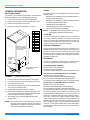
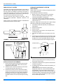
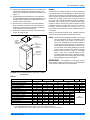
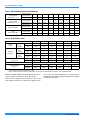
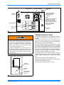
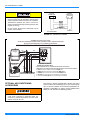
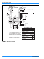
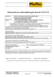
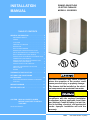
INSTALLATION
MANUAL
DOWNFLOW/UPFLOW
ELECTRIC FURNACE
MODELS: EB SERIES
TABLE OF CONTENTS
GENERAL INFORMATION . . . . . . . . . . . . . . . . . . 2
EB FURNACE NOTES . . . . . . . . . . . . . . . . . . . . . . . 2
CODES . . . . . . . . . . . . . . . . . . . . . . . . . . . . . . . . . . . 2
LOCATION . . . . . . . . . . . . . . . . . . . . . . . . . . . . . . . . 2
FURNACE CLEARANCE . . . . . . . . . . . . . . . . . . . . . 2
RETURN AIR . . . . . . . . . . . . . . . . . . . . . . . . . . . . . . 2
DUCT SYSTEM DESIGN . . . . . . . . . . . . . . . . . . . . . 3
DOWNFLOW FURNACE INSTALLATION
(WITH 7900 SERIES DUCT CONNECTOR) . . . . . . 3
DUCT CONNECTORS (7990 SERIES) . . . . . . . . . . 4
INSTALLATION OF SCREW ATTACHMENT DUCT
CONNECTOR (7990 SERIES) . . . . . . . . . . . . . . . . . 5
INSTALLATION OF TAB ATTACHMENT DUCT
CONNECTOR (7990 SERIES) . . . . . . . . . . . . . . . . . 5
INSTALLATION OF THE FURNACE . . . . . . . . . . . . 6
FURNACE CONVERSION TO UPFLOW
APPLICATION . . . . . . . . . . . . . . . . . . . . . . . . . . . . . 6
WIRING . . . . . . . . . . . . . . . . . . . . . . . . . . . . . . . . . . 7
THERMOSTAT INSTALLATION . . . . . . . . . . . . . . 9
OPTIONAL AIR CONDITIONING
ACCESSORIES . . . . . . . . . . . . . . . . . . . . . . . . . . 10
HIGH PERFORMANCE BLOWER ACCESSORY
PACKAGE . . . . . . . . . . . . . . . . . . . . . . . . . . . . . . . 11
WIRING DIAGRAMS . . . . . . . . . . . . . . . . . . . . . . 11
REPAIR PARTS LIST . . . . . . . . . . . . . . . . . . . . . 17
CAUTION: READ ALL SAFETY GUIDES
BEFORE YOU START TO INSTALL
YOUR UNIT.
SAVE THIS MANUAL
Incorrect installation may create condition
where the operation of the product could
cause personal injury or property damage.
The furnace shall be installed so the electrical components are protected from water.
This product must be installed in strict
compliance with the enclosed installation
instructions and any applicable Local, State
and National Codes including, but not limited to building, electrical, and mechanical
codes. Improper installation will void the
warranty.
66669
035-15266-003 Rev. A (0804)
035-15266-003 Rev. A (0804)
GENERAL INFORMATION
CODES
EB FURNACE NOTES
The electric furnace must be installed in accordance with the
following codes:
The following list includes important facts and information
regarding the EB furnace and its packaging inclusions:
1.
Furnace is rated at 240 volts, 60 Hz, single phase.
2.
Heating and Cooling thermostat is packed with furnace.
3.
Filters are furnished with each model.
4.
Filter size is universal to all models - 16 x 20 x 1.
•
•
•
•
•
Standard for the Installation of Air Conditioning and Ventilating Systems (NFPA 90A)
Standard for the Installation of Warm Air Heating and Air
Conditioning Systems (NFPA 90B)
National Electric Code (NFPA 70)
Canadian Electrical Code, Part I (CSA C22.1)
All local codes (state/county/township).
NOTE: All applicable codes take precedence over any rec19-5/8
SUB-BASE, IF USED,
ADDS 7/8” MORE TO
TOTAL HEIGHT AND
3/8” TO WIDTH.
THERMOSTAT
WIRING
ENTRY
51-5/8
A
B
C
D
E
F
G
H
J
K
L
M
N
1-7/8
2-5/8
3-1/2
1
5-1/16
5-1/2
5-13/16
1
1-3/4
7-13-16
8-5/8
9-7/16
16-1/2
L
M
FURNACE CLEARANCE
Electric furnace is approved for zero (0) in. clearance to combustible material on all or any part of the furnace exterior and
the inlet or outlet duct work. Clearances must be provided
above the furnace for a minimum of 200 sq. inches free opening for return air. For clearances other than shown above see
paragraph on Return Air.
FOR HEATING ONLY FURNACE
OPTIONAL BOTTOM FIELD
WIRING ENTRY
J
H
A
Access for servicing is an important factor in the location of
any furnace. Provide a minimum of 24 inches in front of the
furnace for access to the heating elements and controls. This
access may be provided by a closet door or by locating the
furnace 24 inches from a facing wall or partition.
In order for the furnace to work properly, a closet or alcove
must have a certain total free area opening for return air.
K
B
LOCATION
RETURN AIR
N
FIELD
WIRING
ENTRY
C
ommendation made in these instructions.
E
D
F G
Minimum 200 in2 free area opening.
Use Return Grille 7900-287P/B,
Or any Return Grille with minimum 200 in2 free area opening.
FOR A/C UP TO 4-TONS AND HP UP TO 3 1/2-TONS
FIGURE 1 : FURNACE DIMENSIONS
5.
Furnace size is the same for all models. See Figure 1.
6.
Four-wire thermostat operation for heating and cooling.
7.
Coil cavity built into furnace.
8.
All furnaces are equipped with an air conditioner blower
and is A/C or Heat Pump ready.
9.
Holding strap furnished on top rear of furnace.
10. This furnace is designed for downflow application; however, it may be converted to an upflow application. (See
Page 6 for upflow conversion instruction.)
11. This furnace must not be operated without the front
panel installed.
NOTE: This furnace and its components listed on the A/C
and Heat Pump equipment sticker were listed in
combination as a system by Underwriter's Laboratories for the United States and Canada.
2
Minimum 250 in2 free area opening.
Use Return Grille 7900-287P/B, 1FG0620BK (hinged),
Or Louvered Door 3500-1581, 3500-5851 (bulk pack),
Or any Return Grille with minimum 250 in2 free area opening.
FOR A/C UP TO 5-TONS AND HP UP TO 4-TONS
Minimum 330 in2 free area opening.
Use Return Grille 1RF1025BK, 1FG0125 (hinged),
Or Louvered Door 3500-1591, 3500-5861 (bulk pack),
Or any Return Grille with minimum 330 in2 free area opening.
The return air opening can be located in a closet front door or
a sidewall above the furnace casing, or in a louvered door on
the furnace. If opening for the return air is located in the floor,
side walls or closet door anywhere below furnace casing
height, 6 inches minimum clearance must be provided on the
furnace side where return is located to provide for proper air
flow. See Figure 2. The 6 “ minimum clearance is not required
if there is a return grille installed above the furnace height.
This return grille cannot start more than three feet above the
furnace height.
Unitary Products Group
035-15266-003 Rev. A (0804)
DUCT SYSTEM DESIGN
There must be at least
2 ft. of space available
in front of furnace for
servicing the furnace
when necessary.
23” MIN.
Electric furnace is designed to operate at a given static pressure.
In order to assure proper air flow through the furnace, the distribution system must be designed so that the static pressure
external to the furnace does not exceed the static pressure
rating shown on the furnace rating plate. See Table 3.
The number, size and placement of registers should be such
that even distribution of heat is provided throughout the
home.
20”
A 6 in. clearance is
required if the space
between furnace and
enclosure is used for
return air.
24” MIN.
DOWNFLOW FURNACE INSTALLATION
(WITH 7900 SERIES DUCT CONNECTOR)
We have redesigned our duct connector to eliminate the subbase requirement. Table 1 will help you in deciding the part
number of the new duct connector you need.
If you are installing a new duct connector (7900 Series), refer
to the following instructions. Read carefully the instructions
provided before starting the installation.
20”
Provide adequate clearance for servicing.
FIGURE 2 : ALCOVE & CLOSET CLEARANCES
For Upflow installations, a closet 32 inches wide by 30 inches
deep with a 30-inch wide door is necessary. See Figure 3.
When installing furnace in a separate closet or room which is
accessible only through an outside door, a minimum of 200
sq. in. free opening for return air must be provided. The supply and return air must be ducted, securely attached and be
sealed to the furnace casing if there are grilles in the outside
door to the closet. Openings where ducts pass through walls,
the floor or the ceiling must be sealed to prevent air leakage
into or from closet and the living area.
32”
1-5/8” MIN., 2-3/8 MAX.
30”
RETURN AIR
PASS THROUGH
FRAME WIDTH
30”
WIDE DOOR
25-1/2””
CLOSET
FIGURE 3 : UPFLOW CLOSET CLEARANCE
Provisions shall be made to permit the return of circulating air
from all rooms and living spaces, except the bathroom(s) to
the circulating air supply inlet of the furnace. Failure to comply may cause improper heating and may cause the furnace
to cycle on the limit.
Unitary Products Group
1.
Locate furnace conveniently away from wall facing or
partitions to permit easy removal of components.
2.
A minimum of six (6) inches should be maintained
between the furnace and closet door when door is used
for return air. See Figure 2.
3.
Two (2) feet of space must be available in front of furnace for future servicing (blower or element removal, furnace removal, etc.).
Table 1: DUCT CONNECTOR FOR ELECTRIC
FURNACES
FLOOR TO
DUCT DIMENSIONS
FINGERED
STYLE
SCREW
TAB STYLE
1”
7990-6211
7990-6011
2”
7990-6221
7990-6021
3”
↑↓
↑↓
4”
7990-6241
7990-6041
5”
↑↓
↑↓
6”
7990-6261
7990-6061
7”
7990-6271
7990-6071
8”
7990-6281
7990-6081
9”
↑↓
↑↓
10”
7990-6301
7990-6101
11”
↑↓
↑↓
12”
7990-6321
7990-6121
13”
↑↑
↑↑
14”
NA
NA
15”
NA
NA
↑↓ - Indicates connector above or below could be used
depending on tolerance in floor to duct dimension.
↑↑ - Indicates connector above could be used depending
on tolerance in floor to duct dimension.
↓↓ - Indicates connector below could be used depending
on tolerance in floor to duct dimension.
3
035-15266-003 Rev. A (0804)
DUCT CONNECTORS (7990 SERIES)
These duct connectors are for connecting the furnace to an under the floor supply duct system.
The furnace may be installed on combustible flooring without a separate sub-base.
DUCT CONNECTORS FOR
SCREW ATTACHMENT
18 3
4
14
23
8
23
8
SEE
CHART
23
8
DUCT CONNECTORS FOR
TAB ATTACHMENT
3
18 4
14
23
8
23
8
SEE
CHART
23
8
13
13
12
11
DUCT
11
CUTOUT
DIMENSIONS
3
18 4
43
8
12
18 3
4
43
8
FIGURE 4 : DUCT CONNECTOR DIMENSIONS (7990 SERIES)
=
REAR WALL
OF ENCLOSURE
2-3/4
MIN.
CEILING CUT-OUT
FOR ROOF JACK
FLOOR CUT-OUT
FOR DUCT
CONNECTOR
9-7/8
FLOOR
FLOOR
JOIST
DUCT CONNECTOR
DEPTH
20-1/2
15
23-1/4
FURNACE
OUTLINE
15
OPTIONAL
ELECTRIC
ENTRANCE
2-1/8
1-3/8
SUPPLY DUCT
1-1/8
6-3/8
3-1/4
1
9-3/4
20
FLOOR
FUTURE REFRIGERANT
LINE ENTRANCE
FIGURE 5 : RECOMMENDED FLOOR CUT-OUT (7990
SERIES)
4
FIGURE 6 : DUCT CONNECTOR DEPTH
(7990 SERIES)
Unitary Products Group
035-15266-003 Rev. A (0804)
LOCATOR BRACKET
LOCATOR BRACKET
NAILS, FLAT HEAD SCREWS
OR STAPLES
BEND TABS UNDER
DUCT OPENING TO
SECURE TO THE
SUPPLY DUCT.
NAILS, FLAT HEAD SCREWS
OR STAPLES
SCREWS
FLOOR
FLOOR
SUPPLY DUCT
FIGURE 7 : DUCT CONNECTOR SCREW
SUPPLY DUCT
FIGURE 8 : DUCT CONNECTOR TAB
ATTACHMENT (7990 SERIES)
ATTACHMENT (7990 SERIES)
INSTALLATION OF SCREW ATTACHMENT DUCT
CONNECTOR (7990 SERIES)
INSTALLATION OF TAB ATTACHMENT DUCT
CONNECTOR (7990 SERIES)
1.
Make floor cut out as shown in Figure 5.
1.
Make floor cut out as shown in Figure 5.
2.
Determine the depth of the floor cavity from the surface
of the floor to the top of the supply air duct and select the
appropriate duct connector from the chart.
2.
Determine the depth of the floor cavity from the surface
of the floor to the top of the supply air duct and select the
appropriate duct connector from the chart.
3.
Place locating bracket (supplied with the duct connector)
to the back edge of the floor opening. See Figure 7.
3.
Place locating bracket (supplied with the duct connector)
to the rear of the floor area for the furnace. See Figure 8.
4.
Apply a water based duct sealant to the 1/2" supply duct
attachment flange of the duct connector.
4.
5.
Determine which of the four positions the duct connector
best centers over the supply duct and insert it through
the floor cutout.
Determine which of the four positions the duct connector
best centers over the supply duct and insert it through
the floor cutout.
5.
Mark cut-out location on the supply duct and remove the
duct connector.
6.
Cut out the opening to the supply duct.
7.
Bend tabs down through and back up under the supply
duct.
8.
Secure the duct connector to the floor with nails, flat
head screws or staples.
6.
When properly aligned with the supply duct, secure the
duct connector to the floor with nails, flat head screws or
staples.
7.
Use screws as required to secure the duct connector to
the supply duct.
8.
Cut out the opening to the supply duct. If sealant was not
used, the installer should tape the mating flanges to provide a good air seal.
NOTE: Duct sealant and tape must be classified as meeting
HUD Standard 3280.715, U.L. Standard 181A. Tape
used to provide a better air seal should be approved
by the applicable National or Local Code.
Unitary Products Group
The duct connector is designed for use on ducts down to 12"
in width. When using the connector on smaller width ducts,
there will not be sufficient clearance to bend the tabs on two
sides of the duct connector.
In such cases the tabs may be attached to the sides of the
duct by using sheet metal screws or other suitable fasteners.
Holes for sheet metal screws are provided in three (3) tabs on
each side of the duct connector. If more than 3 tabs need to
be used to provide a more secure and air tight connection,
the remaining tabs can also be fastened to the duct with
screws after drilling the required screw holes.
5
035-15266-003 Rev. A (0804)
PARALLEL DUCT SYSTEM
The EB Duct Connector Insert 37323716001 may be used on
EB Series Electric Manufactured Housing Furnaces where
the duct system runs parallel to the furnace. See Figure 9.
The EB Duct Connector Insert should not be used if the duct
system runs perpendicular to the furnace or if the duct system extends only one direction from the furnace.
The Duct Connector Insert cannot be used with 1” and 2”
Duct Connectors (7990-6011, 7990-6021, 7990-6211, and
7990-6221).
Follow Accessory Kit Installation Instruction 035-20632-001
provided with the Duct Connector Insert.
FURNACE DOOR
FURNACE DOOR
PERPENDICULAR LAYOUT
FURNACE CONVERSION TO UPFLOW
APPLICATION
Upflow furnace conversion is easily accomplished by following the steps listed below:
Provide adequate clearance for servicing:
1.
Before Conversion, locate the furnace conveniently
away from wall facing or partitions to permit easy
removal and installation of components.
2.
Two (2) feet of space must be available in front of furnace for future servicing (blower or element removal, furnace removal, etc.).
3500-5451* Adapter Box and/or 3500-7211* Upflow Flange
Plate Kit are needed prior to following steps below:
1.
Assemble the 3500-5451 filter box per installation provided with kit.
2.
Remove furnace panel.
3.
Remove air filter.
4.
Remove strap on the top of the unit, saving the screw
and strap for later use.
5.
Turn entire unit upside-down, so the filter box is on the
floor.
6.
Remove two (2) screws that are on the front of the unit at
the top. Obtain front panel hanger angle from the upflow
kit 3500-7211*. Secure the hanger angle with two (2)
screws removed from the furance casing See Figure 11.
PARALLEL LAYOUT
FIGURE 9 : DUCT SYSTEM CONFIGURATION
FURNACE SEATED
AGAINST THE
LOCATOR BRACKET
SECURE FURNACE
TO FLOOR WITH
TWO NAILS OR
SCREWS
HANGER ANGLE
CASING
SCREW x 2
FIGURE 11 : HANGER ANGLE ATTACHMENT
FIGURE 10 : INSTALLATION OF FURNACE
INSTALLATION OF THE FURNACE
1.
Remove the front panels and set the furnace onto the
duct connector. Slide it back until the rear of the unit
engages the locator bracket.
2.
Secure the front of the furnace with two screws at the
mounting holes provided. See Figure 10.
3.
Secure the top of the furnace to a structural member
using screw through the strap at the top of the furnace.
Strap may be moved to any of the holes located along
the top back of the furnace. Installer may provide an
equivalent method, such as screws through the casing
side.
6
7.
Attach the strap that was removed in Step 4 to the top,
side or back of the furnace.
8.
Install the duct flange plate on top of the inverted furnace
as shown in Figure 12.
9.
If installaing POS, Standard or Deluxe Air Systems, proceed to Step 10.
Optional start collar for the Economy POS system
shipped with 3500-7211* can be used for blend air flex
duct installation. Punch the lineset knockout out and
position the start collar over it. Duct connector edge can
be pushed under the casing flange and screws provided
can be used to capture the other end of duct connector.
Secure collar to top of furnace.
Unitary Products Group
035-15266-003 Rev. A (0804)
10. Flange plate shipped with 3500-7211* is mounted to the
furnace with eight (8) screws provided. Two (2) blunt
screws are for the holes in the front of the furnace. See
Figure 12.
11. If upflow adapter box kit 3500-5451* is not used, then
our optional filter bracket is provided with 3500-7211* kit.
This filter bracket maybe used to retain filter inside its
original location in the furnace.
12. Secure the top of the furnace to a structural member
using screws and the strap on top of the furnace. The
mobile home manufacturer may provide an equivalent
strap, if required, to secure the furnace.
13. If excessive movement is expected, then some blower
support is recommended.
USE BLUNT
SCREWS HERE
FLANGE
PLATE
(MOUNTED WITH
SCREWS)
WIRING
Furnace wiring is complete except for the power supply and
the thermostat wires. See wiring diagram (or Table 2) for wire
and fuse size. See Table 2 for ground wire sizes. Thermostat
wires connect through side of furnace and should also be no
smaller than 22 gauge. Power wires can enter through the
side of the unit or through the auxiliary entrance, located in
the bottom of the unit. (See Figure 1). When bringing wiring
through the bottom of the furnace, cable connectors must be
installed to hold wiring in place and to relieve any strain on
the wiring. These connectors will also serve as a seal
between the furnace and the floor. Thus, additional sealing is
not required.
(Refer to the National Electrical Code, Canadian Electrical
Code and local codes for wiring material requirements.
NOTE: The furnaces are equipped with either one or two 60
amp circuit breakers. These circuit breakers protect
the wiring inside of the furnace in the event of a
short circuit. Additionally, these breakers provide a
means of disconnecting the power to the unit. The
circuit breakers in the furnace are not meant to protect the branch circuit wiring between the furnace
and the home's breaker panel. General wire and
breaker sizes are shown in Table 2. If sheathed
cable is used, refer to National Electrical Code,
Canadian Electrical Code and local codes for additional requirements concerning supply circuit wiring.
Electrical Data can be found in Table 4.
DUCT
CONNECTOR
LINESET
KNOCKOUT
EB SERIES
(UPFLOW
FURNACE)
IMPORTANT - All installation on field wiring must be
rated at 60ºC or higher. Please refer to the wiring diagrams
on the furnace or this book for more information.
FIGURE 12 : BLOWER BRACKET AND DUCT FLANGE
ATTACHMENT
Table 2:
MODELS
Single Branch Circuit Service *
Nominal Circuit Load - AMPS
Minimum Wire Size (90º)
Minimum Wire Size (75º)
Minimum Wire Size (60º)
Ground Wire Size +
Max. Fuse (or C.B.) - AMPS
Dual Branch Circuit Service
Branch Circuit Load - AMPS
Branch Circuit Min. - AMPS
Minimum Wire Size (90º)
Minimum Wire Size (75º)
Minimum Wire Size (60º)
Ground Wire Size +
Max. Fuse (or C.B.) - AMPS
EB23B
94.0
#2
#1
#0
#6
125
CKT #1 CKT #2
47.3
46.7
59.2
58.4
#6
#6
#6
#6
#4
#4
#10
#10
60
60
EB20B
EB17B
EB15B
2 Leads + 1 Ground CKT#1
84.0
70.7
64.1
#3
#4
#4
#2
#3
#4
#1
#2
#3
#6
#8
#8
110
90
90
CKT #1 CKT #2 CKT #1 CKT #2 CKT #1 CKT #2
44.0
40.0
47.3
23.4
44.0
20.1
55.0
50.0
59.2
29.3
55.0
25.2
#8
#8
#6
#10
#8
#10
#6
#8
#6
#10
#6
#10
#6
#6
#4
#10
#6
#10
#10
#10
#10
#10
#10
#10
60
50
60
30
60
30
EB12B EB10B
50.7
#6
#6
#4
#8
70
44.0
#8
#6
#6
#10
60
NOT
APPROVED
* Requires Jumper Bars (P/N 3500-3781*) - Dual Supply for U.S. Only.
Refer to National Electrical Code. Table 310-16 for Non-Sheathed Conductors.
+ Refer to National Electrical Code. Table 250-95 for Non-Sheathed Conductor Ground Wire.
Unitary Products Group
7
035-15266-003 Rev. A (0804)
Table 3: EB SERIES BLOWER PERFORMANCE
Low Speed
Heating Speed
Models EB10, 12, 15
Medium Speed
Heating Speed
Models EB17, 20, 23
Medium High
with A-Coil in place
High
with A-Coil in place
Static Pressure
(Inches of WC)
.0
.1
.2
.3
.4
.5
.6
.7
.8
CFM (STD. Air)
945
936
936
924
915
889
870
813
705
Static Pressure
(Inches of WC)
.0
.1
.2
.3
.4
.5
.6
.7
.8
CFM (STD. Air)
1160
1145
1145
1140
1129
1109
1073
1027
935
Static Pressure
(Inches of WC)
.0
.1
.2
.3
.4
.5
.6
.7
.8
CFM (STD. Air)
1340
1317
1290
1252
1208
1158
1095
1021
876
Static Pressure
(Inches of WC)
.0
.1
.2
.3
.4
.5
.6
.7
.8
CFM (STD. Air)
1573
1534
1490
1435
1369
1309
1237
1135
1019
Table 4: ELECTRICAL DATA
MODEL NUMBER
D.O.E.
Output
OUTPUT
CAPACITY
EB23B
EB20B
EB17B
EB15B
EB12B
EB10B
240 VAC
60 Hz.
1 Phase
BTU
77,000
67,000
56,000
51,000
39,000
34,000
KW
22.6
19.6
16.4
15.0
11.4
10.0
230 VAC
60 Hz.
1 Phase
BTU
71,000
61,000
52,000
47,000
36,000
31,000
KW
20.8
17.9
15.2
13.8
10.6
9.1
220 VAC
60 Hz.
1 Phase
BTU
65,000
57,000
48,000
43,000
33,000
29,000
KW
19.1
16.7
14.1
12.6
9.7
8.5
Element Capacity
@ 240 VAC
KW
21.6
19.2
16.0
14.4
11.2
9.6
AMPS
90.0
80.0
66.7
60.0
46.7
40.0
50.7*
44.01
Motor AMPS @ 240 V.
Circuit Load AMPS
@ 240 V.
4.0 Maximum
CKT 1
47.3
44.0
47.3
44.0
CKT 2
46.7
40.0
23.4
20.0
1.
Approved for Single Branch Circuit Service Only
Casing or Cabinet must be Permanently Grounded in Accordance with National Electrical Code or other Applicable Codes.
Models for EB23B, EB20B, EB17B and EB15B may be connected to a single or dual branch circuit. (See Table 2.)
These units are shipped from the factory set up for dual
power supply connections. For single power supply connec-
8
tions, jumper bars (P/N 3500-378P*) are required and are
available from the factory. Model for EB12B is factory shipped
with jumper bars in place.
Unitary Products Group
035-15266-003 Rev. A (0804)
SEQUENCERS
CIRCUIT BREAKERS
THERMOSTAT
WIRES
3500-378P* JUMPER
BARS (FOR SINGLE
BRANCH CIRCUIT
SERVICE)
BLOWER
RELAY
NOTE:
AS SHIPPED, THE JUMPER BAR
ASSEMBLY IS SET-UP FOR
BOTTOM ENTRY. FOR SIDE
ENTRY, THE TOP LUG CAN BE
REMOVED AND RE-POSITIONED,
AS SHOWN, TO PROVIDE
PROPER WIRE BENDING
CLEARANCES.
TRANSFORMER
LIMIT
SWITCHES
GROUND
LUGS
FIGURE 13 : CONTROL BOX
THERMOSTAT INSTALLATION
The adjustable heat anticipator in the thermostat is pre-set at
0.4 Amps. This setting should be checked at the time of
installation
For personal safety be sure to turn the electrical
power “OFF" at the household service box and at
the furnace circuit breakers before attempting any
service or maintenance operations. Homeowners
should never perform any maintenance which
requires opening electric box door.
Furnace is equipped with a protective shield over
field wiring connection. When field wiring is completed, shield must be replaced to prevent hazard of
electrical shock when using furnace disconnect.
(See Figure 14.)
In some cases the thermostat may be a “self-setting" type in
which case no Amp. setting will be found on the thermostat,
eliminating the need for any field adjustment.
Thermostat should be located on an inside wall in an open
area to more closely regulate average room air, preferably,
where there is air movement back to furnace. Care should be
used to locate thermostat away from hot air discharge openings, lights, etc. Locating height of thermostat is important.
Thermostat should be located 52 to 66 inches above the
floor. This is sometimes called the comfort zone.
If a condenser with its own Transformer shares a Heat/Cool
Thermostat with this furnace, use a thermostat with isolating
contacts to prevent interconnection of Class II 24 Volt Systems.
Cycle furnace to make sure it will operate correctly.
Maintenance and operating instructions are in the customer
envelope accompanying the furnace.
Give the customer envelope to the home owner.
CIRCUIT
BREAKERS
BLOWER
ELECTRIC
PANEL
FIELD WIRING
PROTECTIVE
SHIELD
FIGURE 14 : FIELD WIRING SHIELD
Unitary Products Group
9
035-15266-003 Rev. A (0804)
COOLING
THERMOSTAT
HEATING
THERMOSTAT
When using separate thermostats, a thermostat
interlock system must be provided to prevent simultaneous operation of the furnace and air conditioner.
Simultaneous operation can result in coach overheating, equipment damage and energy waste. (See
Figures 15 and 16.)
DOUBLE POLE
DOUBLE THROW SWITCH
Do not connect Yellow wire to thermostat until an
outdoor unit is installed.
TO
FURNACE
TO
AIR CONDITIONER
FIGURE 15 : THERMOSTAT WIRING
The EB*B* Furnaces are A/C ready.
All furnaces installations should include a minimum of four conductor thermostat
wiring to accommodate future air conditioning installations.
THERMOSTAT WIRING SCHEMATIC FOR: BLEND AIR AND FURNACE
RED
RED
WHITE
WHITE
GREEN
GREEN
DELUXE BLEND AIR
FRESH
AIR
II
OFF
ALARM
AUTO
BL
AC
K
YELLOW
BLACK
WHITE
GREEN
RED
BLACK
NOT FACTORY
INSTALLED
WIRES FROM FURNACE
STANDARD OR DELUXE
BLEND AIR CONTROL BOX
Four-conductor wire is required for thermostat connection.
Attach the 4 low voltage wires extending from the control box as follows:
1. RED wire from Furnace to thermostat RED wire.
2. WHITE wire from Furnace to thermostat WHITE wire.
3. GREEN wire from Furnace to thermostat GREEN wire.
4. BLACK wire from Furnace to condensing unit contactor.
5. Thermostat YELLOW wire to condensing unit contactor.
FIGURE 16 : THERMOSTAT WIRING
OPTIONAL AIR CONDITIONING
ACCESSORIES
This furnace is already equipped with a blower and control
system to add-on air conditioning up to 4 tons and heat pump
up to 3-1/2 tons. Insulation and coil shelf kit (3500-8941* for
downflow or 3500-8961* for upflow) must be installed when
adding on such remote air conditioning systems.
Failure to install this insulation and coil shelf kit
could result in damage to equipment and/or personal injury. Liability and warranty from the manufacturer could also be void.
10
Unitary Products Group
035-15266-003 Rev. A (0804)
HIGH PERFORMANCE BLOWER ACCESSORY
PACKAGE
All EB furnaces are already equipped with a blower and control system to add-on air conditioning up to 4-tons and heat
pump up to 3 1/2-tons. If the requirement is to achieve more
than specified than the production blower inside the furnace
would have to be replaced with an accessory blower package
3500-7901*. This accessory blower package would deliver air
conditioning up to 5-tons, and heat pump up to 4-tons. Accessory package (3500-7901*) includes blower, insulation, coil
shelf, trap, clamps, etc. Please refer to the installation instructions packed with the accessory package for more information.
All areas around the line sets, drain hoses and other
openings in the coil shelf should be sealed air tight.
Use some moldable compound or caulking to seal
the area. Failure to do so may result in loss of performance and premature compressor failure.
WIRING DIAGRAMS
CAPACITOR
ORG-COMMON.
BLK-COOLING SP.
RED-HEATING SP.
RED
G
W
RH
Y
COND. UNIT
CONTACTOR
2 SPADE (INSUL.) TERMINALS
USED WHEN CHANGING SPEEDS
WHT
TRANSFORMER
BLOWER
RELAY
6
3
YEL
5
4
LINE
1
FUSE
RED
3A
LOAD
RED
BLK
BLK
GRN
ORG
2
HEAT/COOL
T’STAT
BLK
4-SPEED BLOWER
EB SERIES FURNACES
MOTOR
BLU-MED. HIGH SP.
YEL-MED. LOW SP.
BLEND AIR
CONTROL BOX
*
GRN
WHT
N
BR RG
O
BLK
YEL
CIRCUIT #1
BREAKER
H2
H1
60 AMP
YEL
YEL
M3
M1
M4
M2
SEQUENCER
240 VAC.
60 Hz
1 PHASE
YEL
L
R
L
R
ELEMENTS
ORG
YEL
ORG
BLU
GND.
LUG
MODEL: EB10B
SINGLE BRANCH
CIRCUIT SERVICE
LIMIT
SWITCHES
240 VAC - 60 Hz - 1 PHASE
NOTE: IF ANY OF THE ORIGINAL WIRE SUPPLIED
WITH THIS UNIT MUST BE REPLACED. IT
MUST BE REPLACED WITH TYPE 105°C
THERMOPLASTIC OR ITS EQUIVALENT.
FACTORY WIRING SHOWN SOLID. FIELD
WIRING SHOWN BROKEN.
WIRING MUST CONFORM TO LOCAL CODES
APPROVED FOR CU CONDUCTORS ONLY.
34,000
D.O.E. OUTPUT CAPACITY - BTU
4.0
MAX. MOTOR-FLA
SINGLE BRANCH
2 LEADS + 1 GROUND
CIRCUIT SERVICE
44.0
NOMINAL CIRCUIT LOAD-AMPS
WIRE SIZE (75° C) COPPER
#6
WIRE SIZE (60° C) COPPER
#6
MAX. FUSE SIZE (OR CB) - AMPS
60
FIGURE 17 : EB10B WIRING DIAGRAM
Unitary Products Group
11
035-15266-003 Rev. A (0804)
CAPACITOR
GRN
WHT
ORG-COMMON.
YEL-MED. LOW SP.
BLK-COOLING SP.
RED-HEATING SP.
BLU-MED. HIGH SP.
BLEND AIR
CONTROL BOX
4-SPEED BLOWER
EB SERIES FURNACES
MOTOR
RED
*
BLK
N
BR RG
O
HEAT/COOL
T’STAT
G
W
RH
Y
COND. UNIT
CONTACTOR
2 SPADE (INSUL.) TERMINALS
USED WHEN CHANGING SPEEDS
WHT
4
2
GRN
5
6
1
3
TRANSFORMER
LINE
FUSE
RED
BLK
3A
RED
BLK
CIRCUIT #1
BREAKER
M3
M1
H1
M4
M2
60 AMP
YEL
H2
RED
BLK
YEL
ORG
BLU
60 AMP
SEQUENCER
YEL
L
R
L
R
RED
ELEMENTS
NOTE: IF ANY OF THE ORIGINAL WIRE SUPPLIED
WITH THIS UNIT MUST BE REPLACED. IT
MUST BE REPLACED WITH TYPE 105°C
THERMOPLASTIC OR ITS EQUIVALENT.
FACTORY WIRING SHOWN SOLID. FIELD
WIRING SHOWN BROKEN.
WIRING MUST CONFORM TO LOCAL CODES
APPROVED FOR CU CONDUCTORS ONLY.
JUMPER BARS
BLOWER
RELAY
BLK
ORG
YEL
LOAD
240 VAC.
60 Hz
1 PHASE
CIRCUIT #2
BREAKER
GND.
LUG
MODEL: EB12B
SINGLE BRANCH
CIRCUIT SERVICE
LIMIT
SWITCHES
240 VAC - 60 Hz - 1 PHASE
39,000
D.O.E. OUTPUT CAPACITY - BTU
4.0
MAX. MOTOR-FLA
SINGLE BRANCH
2 LEADS + 1 GROUND
CIRCUIT SERVICE
50.7
NOMINAL CIRCUIT LOAD-AMPS
WIRE SIZE (75° C) COPPER
#6
WIRE SIZE (60° C) COPPER
#4
MAX. FUSE SIZE (OR CB) - AMPS
70
FIGURE 18 : EB12B WIRING DIAGRAM
12
Unitary Products Group
035-15266-003 Rev. A (0804)
N
BR RG * CAPACITOR
O
GRN
WHT
ORG-COMMON.
BLK-COOLING SP.
RED-HEATING SP.
BLU-MED. HIGH SP.
YEL-MED. LOW SP.
BLK
BLEND AIR
CONTROL BOX
4-SPEED BLOWER
EB SERIES FURNACES
RED
MOTOR
HEAT/COOL
T’STAT
G
W
Y
COND. UNIT
CONTACTOR
CIRCUIT #1
BREAKER
RED
FUSE
RED 3A
LOAD
BLK
CIRCUIT #2
BREAKER
ORG
BLOWER
RELAY
BLK
GND. LUG
YEL
RED
CIRCUIT #1
BREAKER
GND. LUG
H4
M5
H3
BLK
M6
H2 M5 M1
M2
H1 M6
60 AMP
YEL
WHT
240 VAC.
60 Hz
1 PHASE
60 AMP
6
3
4
5
2
LINE
BLK
YEL
CIRCUIT 1
240 VAC.
60 Hz
1 PHASE
60 AMP
ORG
YEL
YEL
DUAL BRANCH
CIRCUIT SERVICE
ORG
YEL
SEQUENCER
WHT
TRANSFORMER
1
BLU
SINGLE BRANCH
CIRCUIT SERVICE
60 AMP
GRN
2 SPADE (INSUL.)
TERMINALS USED WHEN
CHANGING SPEEDS
MODEL: EB15B
RH
R
L
R
RED
BLK
L
CIRCUIT #2
BREAKER
GND. LUG
L
R
ELEMENTS
LIMIT
SWITCHES
NOTE: IF ANY OF THE ORIGINAL WIRE SUPPLIED WITH
THIS UNIT MUST BE REPLACED. IT MUST BE
REPLACED WITH TYPE 105°C THERMOPLASTIC
OR ITS EQUIVALENT. FACTORY WIRING SHOWN
SOLID. FIELD WIRING SHOWN BROKEN.
WIRING MUST CONFORM TO LOCAL CODES
APPROVED FOR CU CONDUCTORS ONLY.
CIRCUIT 2
240 VAC.
60 Hz
1 PHASE
240 VAC - 60 Hz - 1 PHASE
D.O.E. OUTPUT CAPACITY - BTU
MAX. MOTOR-FLA
‡
SINGLE BRANCH
CIRCUIT SERVICE
NOMINAL CIRCUIT LOAD-AMPS
WIRE SIZE (75° C) COPPER
WIRE SIZE (60° C) COPPER
MAX. FUSE SIZE
(OR CB) - AMPS
DUAL BRANCH
CIRCUIT SERVICE
BRANCH CKT. LOAD-AMPS
BRANCH CKT. MIN. AMPACITY
WIRE SIZE (75° C) COPPER
WIRE SIZE (60° C) COPPER
MAX. FUSE SIZE
(OR CB) - AMPS
51,000
4.0
2 LEADS +
1 GROUND
64.0
#4
#3
90
4 LEADS +
2 GROUNDS
CKT #1 - CKT #2
20.1
44
55
25.2
#6
#10
#6
#10
60
30
‡ REQUIRES JUMPER BARS (P/N 3500-378/*)
FIGURE 19 : EB15B WIRING DIAGRAM
Unitary Products Group
13
035-15266-003 Rev. A (0804)
CAPACITOR
N
BR RG *
O
BLEND AIR
CONTROL BOX
BLK
GRN
WHT
HEAT/COOL
T’STAT
G
W
RH
ORG-COMMON.
BLK-COOLING SP.
YEL-MED. LOW SP.
BLU-MED. HIGH SP.
RED-HEATING SP.
RED
4-SPEED BLOWER
EB SERIES FURNACES
MOTOR
COND. UNIT
CONTACTOR
CIRCUIT #1
BREAKER
6
3
LINE
FUSE
RED 3A RED
LOAD
BLK
ORG
YEL
BLK
BLK
CIRCUIT #2
BREAKER
GRN
GND. LUG
WHT
YEL
WHT
M5
H2 M3
H3
BLK
M6
H1 M4
CIRCUIT #1
BREAKER
YEL
YEL
60 AMP
H4 15
M1
M2
GND. LUG
60 AMP
G
RG
O
R
YEL
O
L
R
L
R
CIRCUIT #2
BREAKER
CIRCUIT 2
240 VAC.
60 Hz
1 PHASE
GND. LUG
BLK
RED
L
ELEMENTS
CIRCUIT 1
240 VAC.
60 Hz
1 PHASE
DUAL BRANCH
CIRCUIT SERVICE
RED
YEL
SEQUENCER
240 VAC.
60 Hz
1 PHASE
60 AMP
5
2
4
TRANSFORMER
1
BLU
SINGLE BRANCH
CIRCUIT SERVICE
60 AMP
2 SPADE (INSUL.)
TERMINALS USED WHEN
CHANGING SPEEDS
BLOWER
RELAY
MODEL: EB17B
Y
240 VAC - 60 Hz - 1 PHASE
R
LIMIT
SWITCHES
NOTE: IF ANY OF THE ORIGINAL WIRE SUPPLIED WITH
THIS UNIT MUST BE REPLACED. IT MUST BE
REPLACED WITH TYPE 105°C THERMOPLASTIC
OR ITS EQUIVALENT. FACTORY WIRING SHOWN
SOLID. FIELD WIRING SHOWN BROKEN.
WIRING MUST CONFORM TO LOCAL CODES
APPROVED FOR CU CONDUCTORS ONLY.
D.O.E. OUTPUT CAPACITY - BTU
MAX. MOTOR-FLA
SINGLE BRANCH ‡
CIRCUIT SERVICE
NOMINAL CIRCUIT LOAD-AMPS
WIRE SIZE (75° C) COPPER
WIRE SIZE (60° C) COPPER
MAX. FUSE SIZE
(OR CB) - AMPS
DUAL BRANCH
CIRCUIT SERVICE
BRANCH CKT. LOAD-AMPS
BRANCH CKT. MIN. AMPACITY
WIRE SIZE (75° C) COPPER
WIRE SIZE (60° C) COPPER
MAX. FUSE SIZE
(OR CB) - AMPS
‡
56,000
4.0
2 LEADS +
1 GROUND
70.7
#3
#2
90
4 LEADS +
2 GROUNDS
CKT #1 - CKT #2
47.3
23.4
29.3
59.2
#6
#10
#4
#10
30
60
REQUIRES JUMPER BARS (P/N 3500-378/*)
FIGURE 20 : EB17B WIRING DIAGRAM
14
Unitary Products Group
035-15266-003 Rev. A (0804)
* CAPACITOR
N
BR RG
O
BLK
GRN
WHT
RED
ORG-COMMON.
BLK-COOLING SP.
YEL-MED. LOW SP.
COND. UNIT
CONTACTOR
4
RED
WHT
6
3
FUSE
RED 3A
LOAD
M6
ORG
YEL
GND. LUG
CIRCUIT #1
BREAKER
YEL
YEL
H2 M3
M1
H1 M4
M2
60 AMP
M8
GND. LUG
RED
RED
R
L
R
L
R
60 AMP
CIRCUIT 2
240 VAC.
60 Hz
1 PHASE
GND. LUG
240 VAC - 60 Hz - 1 PHASE
BLK
L
CIRCUIT #2
BREAKER
BLK
ORG
R
ORG
YEL
L
ELEMENTS
CIRCUIT 1
240 VAC.
60 Hz
1 PHASE
DUAL BRANCH
CIRCUIT SERVICE
BLK
YEL
SEQUENCER
H3
CIRCUIT #2
BREAKER
BLK
YEL
RED
RED
240 VAC.
60 Hz
1 PHASE
60 AMP
5
1
LINE
BLK
BLK
WHT
15
H4 M7 M5
SINGLE BRANCH
CIRCUIT SERVICE
CIRCUIT #1
BREAKER
TRANSFORMER
BLU
MODEL: EB20B
60 AMP
BLU-MED. HIGH SP.
RED-HEATING SP.
HEAT/COOL
T’STAT
G
W
RH
Y
GRN
2 SPADE (INSUL.) TERMINALS
USED WHEN CHANGING
SPEEDS
BLOWER
RELAY
2
BLEND AIR
CONTROL BOX
4-SPEED BLOWER
EB SERIES FURNACES
MOTOR
LIMIT
SWITCHES
NOTE: IF ANY OF THE ORIGINAL WIRE SUPPLIED WITH
THIS UNIT MUST BE REPLACED. IT MUST BE
REPLACED WITH TYPE 105°C THERMOPLASTIC
OR ITS EQUIVALENT. FACTORY WIRING SHOWN
SOLID. FIELD WIRING SHOWN BROKEN.
WIRING MUST CONFORM TO LOCAL CODES
APPROVED FOR CU CONDUCTORS ONLY.
D.O.E. OUTPUT CAPACITY - BTU
MAX. MOTOR-FLA
SINGLE BRANCH ‡
CIRCUIT SERVICE
NOMINAL CIRCUIT LOAD-AMPS
WIRE SIZE (75° C) COPPER
WIRE SIZE (60° C) COPPER
MAX. FUSE SIZE
(OR CB) - AMPS
DUAL BRANCH
CIRCUIT SERVICE
BRANCH CKT. LOAD-AMPS
BRANCH CKT. MIN. AMPACITY
WIRE SIZE (75° C) COPPER
WIRE SIZE (60° C) COPPER
MAX. FUSE SIZE
(OR CB) - AMPS
‡
67,000
4.0
2 LEADS +
1 GROUND
84.0
#2
#1
110
4 LEADS +
2 GROUNDS
CKT #1 - CKT #2
44.0
40
55
50
#6
#8
#6
#6
60
50
REQUIRES JUMPER BARS (P/N 3500-378/*)
FIGURE 21 : EB20B WIRING DIAGRAM
Unitary Products Group
15
035-15266-003 Rev. A (0804)
N
CAPACITOR
BR RG *
O
BLK
GRN
WHT
ORG-COMMON.
BLK-COOLING SP.
YEL-MED. LOW SP.
BLU-MED. HIGH SP.
RED-HEATING SP.
RED
BLEND AIR
CONTROL BOX
4-SPEED BLOWER
EB SERIES FURNACES
MOTOR
HEAT/COOL
T’STAT
G
W
RH
Y
CIRCUIT #1
BREAKER
6
3
TRANSFORMER
LINE
BLK
LOAD
FUSE
RED 3A
BLK
BLK
H2 M3
H3 M8
H1 M4
M6
CIRCUIT #1
BREAKER
YEL
YEL
YEL
GND. LUG
60 AMP
WHT
15
H4 M7 M5
M1
M2
60 AMP
ORG
ORG
YEL
RED
R
L
R
L
R
L
R
ELEMENTS
BLK
L
BLK
CIRCUIT #2
BREAKER
RED
CIRCUIT 1
240 VAC.
60 Hz
1 PHASE
DUAL BRANCH
CIRCUIT SERVICE
BLK
YEL
SEQUENCER
RED
CIRCUIT #2
BREAKER
GND. LUG
ORG
RED
YEL
240 VAC.
60 Hz
1 PHASE
60 AMP
RED
WHT
4
5
1
2
2 SPADE (INSUL.) TERMINALS
USED WHEN CHANGING
SPEEDS
BLOWER
RELAY
SINGLE BRANCH
CIRCUIT SERVICE
60 AMP
GRN
BLU
MODEL: EB23B
COND. UNIT
CONTACTOR
LIMIT
SWITCHES
NOTE: IF ANY OF THE ORIGINAL WIRE SUPPLIED WITH
THIS UNIT MUST BE REPLACED. IT MUST BE
REPLACED WITH TYPE 105°C THERMOPLASTIC
OR ITS EQUIVALENT. FACTORY WIRING SHOWN
SOLID. FIELD WIRING SHOWN BROKEN.
WIRING MUST CONFORM TO LOCAL CODES
APPROVED FOR CU CONDUCTORS ONLY.
CIRCUIT 2
240 VAC.
60 Hz
1 PHASE
GND. LUG
240 VAC - 60 Hz - 1 PHASE
D.O.E. OUTPUT CAPACITY - BTU
MAX. MOTOR-FLA
SINGLE BRANCH ‡
CIRCUIT SERVICE
NOMINAL CIRCUIT LOAD-AMPS
WIRE SIZE (75° C) COPPER
WIRE SIZE (60° C) COPPER
MAX. FUSE SIZE
(OR CB) - AMPS
DUAL BRANCH
CIRCUIT SERVICE
BRANCH CKT. LOAD-AMPS
BRANCH CKT. MIN. AMPACITY
WIRE SIZE (75° C) COPPER
WIRE SIZE (60° C) COPPER
MAX. FUSE SIZE
(OR CB) - AMPS
77,000
4.0
2 LEADS +
1 GROUND
94.0
#1
#0
125
4 LEADS +
2 GROUNDS
CKT #1 - CKT #2
47.3
46.7
59.2
58.4
#6
#6
#4
#4
60
60
‡ REQUIRES JUMPER BARS (P/N 3500-378/*)
FIGURE 22 : EB23B WIRING DIAGRAM
16
Unitary Products Group
035-15266-003 Rev. A (0804)
REPAIR PARTS LIST
11
MODELS
EB10B
EB12B
EB15B
EB17B
EB20B
EB23B
13
1
4
2
3
9
15
10
18
20
23
21
24
26
12
27
19
22
25
17
28
5
6
29
7
Unitary Products Group
30
18
17
035-15266-003 Rev. A (0804)
ITEM
1
2
3
4
5
6
7
8*
9
10
11
12
13
14
15
16*
17
Heater Element
19
20
21
22
Transformer (240/24V-40A)
Sequencer
Bracket (Circuit Breaker)
Limit Switch (For furnaces produced
before 3/98)
Circuit Breaker (1 Req’d)
Circuit Breaker (2 Req’d)
Buss Bar
(See Note 2)
Ground Lug (Large)
Ground Lug (Small)
Drain Tube
(See Note 1)
Condensate Trap
(See Note 1)
Coil Shelf
(See Note 1)
Coil Shelf Panel
(See Note 1)
Insulation, Cover Panel (See Note 1)
24
25
26
27
28
29
30
31*
32*
33*
34*
35*
36*
18
Blower Wheel
Limit Baffle (For furnaces produced
before 3/98)
Heater Element (For furnaces produced before 3/98)
18
23
NOTE:
DESCRIPTION
Thermostat (Heat/Cool)
Front Panel
Front Panel (Front Return 4-Ton)
Front Panel (Front Return 5-Ton)
Filter (16 x 20 x 1)
Filter (20 x 20 x 1) (Front Return Panel)
Support Angle
Cover, Electric Box
Cover (Service Entrance)
Sub-base (Optional)
Sub-base (M10) (Optional)
Blower Motor (For furnaces produced
before 2/99)
Blower Motor (For furnaces produced
after 2/99)
Capacitor (7.5MFD/370V)
Relay
Motor Mount Assembly (1PC) (Kit)
(See Note 3)
EB10B
EB12B
EB15B
025-38746-000
3500-1751/B
3500-1581
3500-1591
1214-2511
1214-2521
3500-1861
3500-2351/A
3500-1271
3500-1071/B
3500-5221
1468-243P/A
025-38746-000
3500-1751/B
3500-1581
3500-1591
1214-2511
1214-2521
3500-1861
3500-2361/A
3500-1271
3500-1071/B
3500-5221
1468-243P/A
025-38746-000
3500-1751/B
3500-1581
3500-1591
1214-2511
1214-2521
3500-1861
3500-2361/A
3500-1271
3500-1071/B
3500-5221
1468-243P/A
024-27651-000
024-27651-000
024-27651-000
1499-4461
3110-3301
373-19831-001
1499-4461
3110-3301
373-19831-001
1499-4461
3110-3301
373-19831-001
1472-2831
3500-129
1472-2831
3500-101
1472-2831
3500-101
(9.6Kw)
3500-4101
(11.2Kw)
3500-4121
(9.6Kw)
3500-410P/A
(11.2Kw)
3500-412P/A
3300-3861
3110-3571
3500-128
2 ea. 7142-3091
3300-3861
3110-3571
3500-128
2 ea. 3500-3121
(Open 150, Close 110)
(Open 150, Close 120)
3500-377P/A
--3500-378P
1216-231
--029-22184-001
3240-3051
3500-174
3500-171
010-69111-001
--3500-377P/A
3500-378P
1216-231
--029-22184-001
3240-3051
3500-174
3500-171
010-69111-001
(4.8Kw) & (9.6Kw)
3500-4051 &
3500-4101
(4.8Kw) & (9.6Kw)
3500-405P/A &
3500-410P/A
3300-3861
3110-3571
3500-128
3 ea. 3500-3151/A
(Open 150, Close 110)
--3500-377P/A
3500-378P
1216-231
1216-229
029-22184-001
3240-3051
3500-174
3500-171
010-69111-001
See Page 20 Field Fix Kits
Wiring diagram
Fuse
035-15274-001
025-32746-026
035-15275-001
025-32746-026
*Not Shown
Major components and suggested stocking items are shown with shaded item number.
--- Not applicable to specified model.
All parts with three digit suffix numbers are “Special Order” parts. These parts are subject to factory
availability and require extra time for delivery.
1 Not Standard with furnace, contained in accessory kit no. 3500-8941.
2 Standard on EB12B.
035-15276-001
025-32746-026
<
Unitary Products Group
035-15266-003 Rev. A (0804)
ITEM
1
2
3
4
5
6
7
8
9
10
11
12
13
14
15
16
17
Thermostat (Heat/Cool)
Front Panel
Front Panel (Front Return 4-Ton)
Front Panel (Front Return 5-Ton)
Filter (16 x 20 x 1)
Filter (20 x 20 x 1) (Front Return Panel)
Support Angle
Cover, Electric Box
Cover (Service Entrance)
Sub-base (Optional)
Sub-base (M10) (Optional)
Blower Motor (For furnaces produced
before 2/99)
Blower Motor (For furnaces produced
after 2/99)
Capacitor (7.5MFD/370V)
Relay
Motor Mount Assembly (1PC) (Kit)
Blower Wheel
Limit Baffle (For furnaces produced
before 3/98)
Heater Element (For furnaces produced
before 3/98)
18
Heater Element
19
20
21
22
Transformer (240/24V-40A)
Sequencer
Bracket (Circuit Breaker)
Limt Switch (For furnaces produced
before 3/98)
Circuit Breaker (2 Req’d) (See Note 2)
Buss Bar
Ground Lug (Large)
Ground Lug (Small)
Drain Tube
(See Note 1)
Condensate Trap
(See Note 1)
Coil Shelf
(See Note 1)
Coil Shelf Panel
(See Note 1)
Insulation, Cover Panel (See Note 1)
23
24
25
26
27
28
29
30
31*
32*
33*
348
35*
36*
NOTE:
DESCRIPTION
(See Note 3)
EB17B
EB20B
EB23B
025-38746-000
3500-1751/B
3500-1581
3500-1591
1214-2511
1214-2521
3500-1861
3500-2361/A
3500-1271
3500-1071/B
3500-5221
1468-243P/A
025-38746-000
3500-1751/B
3500-1581
3500-1591
1214-2511
1214-2521
3500-1861
3500-2361/A
3500-1271
3500-1071/B
3500-5221
1468-243P/A
025-38746-000
3500-1751/B
3500-1581
3500-1591
1214-2511
1214-2521
3500-1861
3500-2361/A
3500-1271
3500-1071/B
3500-5221
1468-243P/A
024-27651-000
024-27651-000
024-27651-000
1499-4461
3110-3301
373-19831-001
1499-4461
3110-3301
373-19831-001
1499-4461
3110-3301
373-19831-001
1472-2831
3500-129
1472-2831
3500-129
1472-2831
3500-129
(4.8Kw) & (11.2Kw)
3500-4051 &
3500-4121
(5.6Kw) & (10.4Kw)
3500-406P/A &
3500-411P/A
3300-3861
3115-3571
3500-128
3 ea. 7142-3091
2 Ea. (9.6Kw)
3500-4101
3300-3861
3120A3571
3500-128
4 ea. 7142-3091
(Open 150, Close 110)
(Open 150, Close 110)
3500-377P/A
3500-378P
1216-231
1216-229
029-22184-001
3240-3051
3500-174
3500-1711
010-69111-001
3500-377P/A
3500-378P
1216-231
1216-229
029-22184-001
3240-3051
3500-174
3500-1711
010-69111-001
(10.4Kw) & (11.2Kw)
3500-4111 &
3500-4121
(10.4Kw) & (11.2Kw)
3500-411P/A &
3500-412P/A
3300-3861
3120A3571
3500-128
4 ea. 7142-3091
(Open 150, Close 110)
3500-377P/A
3500-378P
1216-231
1216-229
029-22184-001
3240-3051
3500-174
3500-1711
010-69111-001
2 Ea. (9.6Kw)
3500-410P/A
<
<
<
<
<
See Page 20 For Field Fix Kits
Wiring diagram
Fuse
035-15277-001
025-32746-026
035-15278-001
025-32746-026
*Not Shown
Major components and suggested stocking items are shown with shaded item number.
--- Not applicable to specified model.
All parts with three digit suffix numbers are “Special Order” parts. These parts are subject to factory
availability and require extra time for delivery.
1 Not Standard with furnace, contained in accessory kit no. 3500-8941.
2 Standard on EB12B.
Unitary Products Group
035-15279-001
025-32746-026
<
19
FIELD FIX KIT FOR EB12 (A&B) MANUFACTURED PRIOR TO AUGUST 1995
FIELD FIX KT 3500-7121 CONTAINS:
ITEM
DESCRIPTION
PART NO.
31*
1 Each Limit Baffle
3500-101
32*
2 Each LImit Switch
3500-3121
FIELD FIX KIT FOR EB15 (A&B) MANUFACTURED PRIOR TO AUGUST 1995
FIELD FIX KT 3500-7151 CONTAINS:
ITEM
DESCRIPTION
PART NO.
33*
1 Each Limit Baffle
3500-101
34*
2 Each LImit Switch
3500-3151/A
Subject to change without notice. Printed in U.S.A.
Copyright © by York International Corp. 2004. All rights reserved.
Unitary
Products
Group
035-15266-003 Rev. A (0804)
Supersedes: 035-15266-002 Rev. D (0304)
P.O.
Box
19014
Wichita
KS
67204-9014