1
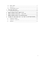
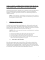
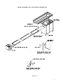
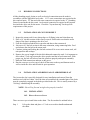
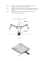
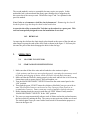
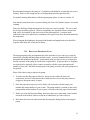
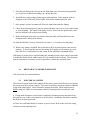
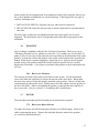
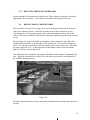
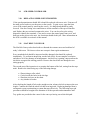
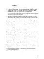
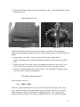
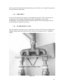
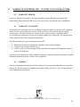
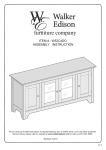
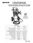
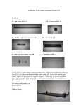
TABLE OF CONTENTS
INSTALLATION & OPERATING INSTRUCTION MANUAL FOR MODEL SBC –
SLAT BELT CONVEYOR SYSTEM
1.
GENERAL INSTALLATION _________________________________________3
1.1.
ELECTRICAL FIELD WORK___________________________________________ 3
1.2.
BUILDING CONNECTIONS ___________________________________________ 5
1.3.
INSTALLATION OF CONVEYOR BELT _________________________________ 5
1.4.
INSTALLATION AND REMOVAL OF AEROWERKS SLAT ________________ 5
1.4.1. Installation ________________________________________________________ 5
1.4.2. How to install slats __________________________________________________ 5
1.4.3. Removal __________________________________________________________ 7
2.
OPERATION ______________________________________________________7
2.1.
SLAT BELT CONVEYOR _____________________________________________ 7
2.2.
START AND STOP INSTRUCTIONS ____________________________________ 7
2.2.1. Slat belt wash system ________________________________________________ 8
3.
MAINTENANCE ___________________________________________________9
3.1.
BEARINGS__________________________________________________________ 9
3.2.
CHAIN TAKE UP ____________________________________________________ 9
3.2.1. Slat belt chain ______________________________________________________ 9
3.2.2. Drive chain _______________________________________________________ 10
3.3.
DETERGENT PUMP _________________________________________________ 10
3.3.1. Replacing detergent pump ___________________________________________ 11
3.4.
DRIVE SHAFT AND DRIVE SPROCKET________________________________ 12
3.5.
ELECTRICAL SYSTEM ______________________________________________ 12
3.6.
GEAR BOX ________________________________________________________ 13
3.6.1. Replacing gearbox _________________________________________________ 13
3.7.
MOTOR ___________________________________________________________ 13
3.7.1. Replacing drive motor ______________________________________________ 13
3.7.2. Replacing drive motor brushes ________________________________________ 14
3.8.
RETURN TRACK CORNER GUIDES ___________________________________ 14
3.9.
SCR SPEED CONTROLLER __________________________________________ 15
3.10.
REPLACING SPEED POTENTIOMETER ________________________________ 15
3.11. SLAT BELT CONVEYOR ____________________________________________ 15
3.11.1.
Daily __________________________________________________________ 16
3.11.2.
Weekly ________________________________________________________ 16
3.11.3.
Monthly _______________________________________________________ 16
3.11.4.
Semi-annually___________________________________________________ 17
3.11.5.
How to install slats _______________________________________________ 17
1
4.
3.12.
SPRAY ARMS ______________________________________________________ 17
3.13.
SPROCKETS _______________________________________________________ 18
3.14.
WATER MIXING VALVE ____________________________________________ 18
TROUBLE SHOOTING ____________________________________________19
4.1.
SLAT BELT CONVEYOR ____________________________________________ 19
5.
REPLACEMENT PARTS - DRIVE UNIT _____________________________23
6.
REPLACEMENT PARTS LIST --- TAIL UNIT ________________________24
7.
REPLACEMENT PARTS CONVEYOR TRACKS _____________________25
8.
WARRANTY FOR MODEL SBC - SLAT BELT CONVEYOR SYSTEM ___28
8.1.
WARRANTY PERIOD _______________________________________________ 28
8.2.
WARRANTY COVERAGE____________________________________________ 28
8.3.
GENERAL _________________________________________________________ 28
2
INSTALLATION & OPERATING INSTRUCTION MANUAL
FOR MODEL SBC – SLAT BELT CONVEYOR SYSTEM
The following instructions for a Slat Belt Conveyor should be carefully read and followed.
Any deviation will affect the warranty of this machine. The conveyor unit shall be
installed by or under the supervision of Aerowerks or its authorized representatives to
validate the warranty.
NOTE: A "Layout Drawing” representing the overall conveyor system, specific to
this project is included in this manual. Owners and maintenance personnel should
become familiar with this document.
1.
GENERAL INSTALLATION
Carefully clean all materials from top and bottom tracks. Set the machine in place and
level in the correct position. Bolt together the drive and tail units. Extreme care shall be
taken to install the return track into the drive tank. The edges of the return track extending
inside the drive unit shall be bent outwards as shown in the figure 1.0
CAUTION: These are the most vital instructions to be followed for the installation
of SBC conveyor system.
•
•
•
•
1.1.
The return track shall be tack welded to the center of the drive unit.
All return track joints shall be field welded and ground smooth.
All the field welded top bed joints also shall be ground smooth.
Place and slide the bed in proper position over the drive unit and fasten down
with the studs and bolts supplied for this purpose.
ELECTRICAL FIELD WORK
Most of the projects require some electrical fieldwork. The details are included in the
'Layout Drawing'. All the work must be done in accordance with local electrical codes.
Wiring must be run in liquid-tight conduit. Usually the electrical work involves making
connections to the accumulation switches, or auxiliary push buttons. Locate and mount the
pre-wired Main Control Panel housing and make appropriate connections.
3
FIELD ASSEMBLY OF CONVEYOR COMPONENTS
Figure 1.0
4
1.2.
BUILDING CONNECTIONS
All the plumbing supply, drains as well as electrical connections must be made in
accordance with the applicable local codes. 1-1/2" waste connections are required at the
drive and tail units. 1/2" hot and cold-water connection is required to the “Y” plumbing
fixture located inside the drive unit. An electrical connection is required at the junction
box inside the drive unit for the motor. Check the "Layout drawing" for the specific
requirements of this project.
1.3.
INSTALLATION OF CONVEYOR BELT
1. Inspect the return track for any sharp edges or ill-fitting joints and clean them up.
2. Place a 10’ slat belt section on the conveyer track. Please make sure that the arrow
shape of the slats is pointing to the drive end.
3. Feed the slat belt around the drive sprocket and then to the return track.
4. Join a next 10’ slat belt section in the same orientation, using connecting links. Feed
and advance the slat belt in the return track.
5. Continue joining and feeding the slat belt sections till it covers entire return track, tail
unit sprocket and overlaps.
6. Remove the excess length of the slat belt chain and connect the ends. It is important to
allow about 2” belt sag between the drive sprocket and the in feed return track. With
proper sag, the belt will release from the sprockets properly and operate smoothly.
7. Make the field connections and turn on the power.
8. Run the conveyor on a low speed, check all the turns on the top and bottom track as
well as inside the drive and tail unit for quiet operation.
1.4.
INSTALLATION AND REMOVAL OF AEROWERKS SLAT
The Aerowerks slat is specially designed for easy installation and removal from the
stainless steel side-bow chain. Once the slats are assembled, the extended pins of the chain
must be completely engaged in the holes provided in the slat. This is usually ensured by a
"clicking" sound during the assembly.
NOTE: Slat will lay flat and straight when properly installed.
1.4.1. INSTALLATION
1.4.2. HOW TO INSTALL SLATS
There are two ways to install slats on the chain. The first method is outlined below.
Step 1
Lift up the chain and place a ¾” rod or screwdriver handle underneath
the chain.
5
Step 2:
Step 3:
Step 4
Place Slat Tool at the center of the slat as shown below. Use your
fingers to grasp the ends of the slat and arch the slat
With the slat arched push onto the chain and engage the pins on the chain
into the holes on the slat. A slight “click” may be heard when the slat is
engaged.
Remove the support. If slat is properly installed, it will lay flat and
straight with respect to the other slats.
Figure 2.0
Figure 3.0
6
The second method is easier to accomplish, but may require two people. In this
method the belt is advanced until the empty spot (missing slat) is stopped on the
drive sprocket of the conveyor unit. Then follow steps 2 and 3 as explained in the
previous method.
Note: Under no circumstances shall the slats be hammered. Hammering the slat will
break the plastic lugs that keep the chain locked inside them.
Aerowerks also offers a custom Slat Tool that can be ordered as a spare part. This
tool has been specially designed to ease the installation of new slats.
1.4.3. REMOVAL
In removing the slat from the chain simply place thumbs at the center of the slat and use
other fingers to grasp the ends of the slat to arch as shown in the figure 2. Pull away the
slat once the pins on the chain disengage the holes in the slat lugs.
2.
OPERATION
2.1.
SLAT BELT CONVEYOR
2.2.
START AND STOP INSTRUCTIONS
1. Make sure that all the drive units and tail tanks have the strainers in place.
( if the strainers and doors are not replaced properly, operating the system may result
in flooding and clogging of drains, which will not be covered under warranty)
2. Make sure that the slat belt is sitting properly in the track and belt line is free from any
obstructions such as spoons, knives, forks and napkins, etc.
3. Turn the MAIN DISCONNECT SWITCH located on the main control panel to the
“ON” position.
4. Then push the green ‘START’ button for whichever Slat Belt Conveyor you wish to
start. (The Slat Belt Conveyor can be used as Tray Conveyor, Plate Conveyor or
accumulation Conveyor. Some system may consist of multiple slat belt conveyors).
5. Before shutting down the conveyor push the red ‘STOP’ button. Finally turn the
‘MAIN DISCONNECT SWITCH’ to the ‘OFF’ position.
6. The conveyor stops automatically when a stack of dishes reaches the end and actuates
the limit switch by pushing the flap. The conveyor runs again once dishes are cleared.
The slat belt plate conveyor comes with a limit switch for accumulation purposes as
shown in the figure 4.0
7
Figure 4.0
2.2.1. SLAT BELT WASH SYSTEM
1. Turn the Switch to SPRAY & DETERGENT position to start the belt wash system
2. The Detergent Pump is preset for an optimum flow of the detergent and water
mixed solution. The setting can be changed for the desired flow by referring to the
service manual.
3. On some conveyor models LOW DETERGENT warning light on the control panel
glows when the solution tank runs out of the detergent. Fill the detergent to the
solution tank as and when the level drops.
4. To shut down the Wash Belt System, use the selector switch to switch from SPRAY
& DETERGENT to SPRAY for 5 minutes to make sure that the belt is completely
rinsed. Turn off the belt wash. Then bring the speed of the conveyor to zero, Push
the red STOP button and turn the Main Disconnect Switch to OFF.
5. Once the unit is shut off, the daily clean up procedure may begin. No service or
cleaning should be done on the unit when the conveyor is running. For more
information please see section 3.1.1.1.
6. The Main Disconnect switch on the Aerowerks control panel also has a special lock
out feature that disables power to the unit and can be locked so that nobody can
accidentally start the conveyor.
Note: Turn on the belt wash system when the conveyor is running.
8
3.
MAINTENANCE
Our Conveyor Systems are built with high quality standards to provide a reliable service
and trouble free operation. The life of the equipment can be extended by regular
maintenance. It is strongly recommended to get the equipment serviced by Aerowerks or its
authorized service agent.
Following are the recommended maintenance schedule. ( A spare part reference sheet is
provided at the end of this manual). Please refer to this list when ordering your parts.
3.1.
BEARINGS
The two- (2) 1” flange bearings are located in the drive unit. These bearings shall be
lubricated with Food Grade Grease, once a year, from date of startup.
3.2.
CHAIN TAKE UP
3.2.1. SLAT BELT CHAIN
The slats are attached on a stainless steel slat belt chain. Under normal operating
conditions this chain should never need any replacement. However over a period of time,
the tension in the chain produces permanent stretch and requires an adjustment to reduce
the length.
Follow these steps to reduce the length of the slat belt chain.
Step 1:
Step 2:
Step 3:
Step 4:
Step 5:
Step 6:
Remove about 5 slats from the chain near the connecting links.
Remove the connecting links to disconnect the chain
Pull both ends of the chain together.
Remove the excess stretch in the chain by removing required
number of links. Removal of each link reduces the overall chain
length by 1 ½ “
Connect the both ends of the chain using the pin and connecting
links.
Run Conveyor and inspect the slat belt for smooth operation. If the
slack is still too excessive, repeat steps 2 through 6.
Note: It is important to allow about 2” belt sag between the drive sprocket
and the in feed return track. With proper sag, the belt will release from the
sprockets properly and operate smoothly
9
Normal Belt Slack
Drive Unit Showing Normal Belt Slack
Figure 5.0
3.2.2. DRIVE CHAIN
The gearbox coupled to the motor transmits power to the drive sprocket through a stainless
steel chain. This chain also stretches and becomes loose over a period of conveyor
operation. Loosening the bolt that secures the chain take up bracket, repositioning the
bracket and tightening the bolt can remove the slack in the chain. When this is done make
sure that the chain should allow about ¾” lateral movement.
3.3.
DETERGENT PUMP
The Detergent Feed Pump located within the Drive Unit controls the amount of detergent
dispensed. When the unit is new the system requires higher flow of the detergent.
Accordingly the pump is set for higher flow by Aerowerks when the new unit is supplied.
After two weeks of full operation, the pump discharge shall be readjusted.
The setting of the pump discharge is based on the following factors.
1. Length of belt line
2. System usage
3. Cleanliness of the belt
10
Recommended setting for the pump is 3.5 and belt wash should be on when the conveyor is
running. However the setting may be varied depending upon the specific needs.
For trouble shooting information of the detergent pump, please see the see section: 4.1.
Note that the pump head valves, injection fitting, the Foot-valve/Strainer require occasional
cleaning.
Due to the build up of hardened material, the valves may not be reusable. The valves and
the O-rings should be replaced. When re-assembling, care should be taken to ensure that
both valves are installed on the correct side of the metering block. An arrow mark
embossed on the valve indicates its orientation with respect to the flow direction marked on
the pump head.
When changing the diaphragm, the pump head chamber and pump head cover should be
wiped to make them free of any dirt or debris.
3.3.1. REPLACING DETERGENT PUMP
The detergent pump plays an important role in the operation of your conveyor system by
periodically cleaning and lubricating slat belt system. A poorly maintained belt will create
sanitation and mechanical problems. As discussed in the previous section, it is imperative
that the operation of the pump be checked on a regular basis. If injector tubes or couplings
are required to be replaced, please contact Aerowerks with the correct part and model
number of your unit. When the internal parts of the pump are faulty, the entire pump has to
be replaced.
Please follow these steps to replace the pump:
1. To make sure that the pump is defective, please check weather the electrical
connections are loose at the junction box, inside the drive unit or the pump lines are
clogged or detergent source is empty.
2. Once the pump has been proved to be faulty call Aerowerks with the proper part
number and model number of your system. The pump number is located on the actual
pump and the model number of your system is located on the title page of this manual.
3. Before servicing the Detergent Pump, disconnect the power at the main circuit breaker
and at the main control center to avoid an accidental start up of the conveyor.
4. Disconnect the electrical connections and all pump tube fittings before removing the
pump.
11
5. Once the tube fittings have been removed flush them out to clean any detergent build
up. If you have ordered new tubing you can skip this step.
6. Install the new pump using existing support studs and nuts. If the support studs are
damaged or have fallen off, please replace them before installing the new unit.
7. Once pump is in place reconnect all electrical connections and tube fittings.
8. Check the detergent output of your new pump and make sure it is set to the same setting
as your old pump. The output of the pump is set by Aerowerks for optimum flow and
may not coincide with your previous setting.
9. Before starting the unit make sure that the detergent tank is full and the float in the
detergent tank is sitting at the bottom.
10. Start the Slat Belt Conveyor System (See Section: 2.1.) in order to test the pump.
11. When a new pump is installed, the suction line will be dry and requires some time for
priming. To overcome this increase the setting of the pump to its maximum (set to 6)
Once the flow is established reset the setting for the optimum recommended flow.
If the pump is required to be replaced within the warranty period, please contact Aerowerks
to obtain the Return Goods Authorization (R.G.A) number before ordering. The old pump
must be returned to Aerowerks as soon as possible to validate the warranty claim.
3.4.
DRIVE SHAFT AND DRIVE SPROCKET
Call Aerowerks for recommendations.
3.5. ELECTRICAL SYSTEM
The electrical system control unit contains all the relays, starters and other devices required
for operation of the conveyor control. There may be auxiliary start-stop stations in addition
to the main control panel. Check schematic drawing for details. Main control panel is
NOT waterproof. Under no circumstances shall the control panel be hosed down with
water.
A 15-amp main disconnect circuit breaker completely disconnects motor and panel from
line and serves as a short circuit protection for the motor. In addition, the motor controller
has built in overload protection.
All fuses are sized individually for control or power circuit. Refer to the electrical wiring
schematics when replacing fuses.
12
Some systems may be equipped with an accumulation switch, which stops the conveyor in
the event of product accumulation (see Layout Drawing). Following are the two types of
switches commonly used:
1. INSTANT STOP SWITCH: Stops the conveyor when switch is depressed.
2. DELAY SWITCH: Stops the conveyor only if switch is depressed for a predetermined
time limit.
The Delay type switch has a time adjustment inside the control panel (see electrical
diagrams). The desired time can be set depending on the individual requirements of the
installation.
3.6.
GEAR BOX
First oil change is mandatory after the first 100 hours of operation. Then every year or
2500 hours of normal service, whichever comes first. Use a turbine type of oil or SAE 50
grade oil. The oil viscosity for the particular unit is specified on the metal plate fixed on the
gearbox. To drain the oil from the gearbox, take out the socket headed screw located at the
bottom. When the oil is drained completely, replace the screw. Remove the oil breather
located on top of the gearbox and fill the fresh oil until the specified level is reached.
Replace the oil breather. A level glass is provided in the gearbox to check and monitor the
oil level.
3.6.1. REPLACING GEARBOX
The first step is to turn off the main power breaker to the system. Loosen the bolt that
secures the chain take up bracket, to release the tension on the drive chain. When chain
becomes loose remove it from the sprocket mounted on the gearbox. Remove all the bolts
connecting the gearbox to the motor. Finally remove the bolts which secure the gearbox to
the drive unit frame. When re-assembling the gearbox, go through the same steps but in
the reverse order. Also see section 3.11 on adjusting drive chain tension.
3.7.
MOTOR
The motor has been lubricated for life and hence no lubrication is required.
3.7.1. REPLACING DRIVE MOTOR
To replace the motor, turn off the main power breaker to cut off the supply. Remove the
cables connecting the motor. Remove the bolts that fasten the motor to the gearbox.
An electrician should do this job.
13
3.7.2. REPLACING DRIVE MOTOR BRUSHES
Worn out brushes of the motor need replacement. Please contact Aerowerks to locate the
right brushes for your motor. An electrician or mechanic should perform this job.
3.8.
RETURN TRACK CORNER GUIDES
The Aerowerks conveyor belt is unique in its use of small guide wheels on the bottom to
reduce the cornering friction. As the belt is upside down on the return track, special
cornering guides are employed to engage these wheels and guide the belt to go around
corners. The proper operation of the system is dependent upon these guides being correctly
set up.
When properly set up the belt should go around the corners without the tips of the slats
touching either the inside or outside edges of the return track. The system is designed to
allow a 1/8” gap between the tips of the slats and the edges of the return track. Also adjust
the guide rails to have 1/8” vertical gap between the bottom surface of the slat and the
guide rail. (Please refer the figure 6.0)
This adjustment once completed, the guide rail should be locked in place by tightening the
nuts. Apply the sealant such as Loctite 262 to the bolts to prevent it by loosening due to
the vibration during operation.
Figure 6.0
The most common indication of the return track misalignment is wearing of the slat belt on
one side.
14
3.9.
SCR SPEED CONTROLLER
3.10. REPLACING SPEED POTENTIOMETER
If the speed potentiometer should fail it should be replaced with a new unit. First turn off
the main power breaker to cut the power to the system. To gain access, open the front
cover of the control panel by removing the screws. It is hinged and should be gently
lowered. Note the existing wire connections to all the terminals of the speed controller
unit. Replace the new unit and reconnect the wires. You can also refer to the wiring
diagram to identify the terminals. Close and re-secure the control panel front cover, and
then turn on the power to the unit. An electrician should do this job. More information on
the SCR is available in section 4 of this manual.
3.11. SLAT BELT CONVEYOR
The Slat Belt Conveyor has been built to withstand the extreme stress and workload of
today’s dish room. This however does not exempt it from regular maintenance.
Every month the belt should be inspected and the damaged slats should be replaced
immediately. To perform an inspection, run the belt slowly for one complete revolution
and observe it for any damage or misalignment. An ideal way is putting a tape mark on the
slat belt to recognize the starting position. Remove the slats which are damaged or not
sitting properly
The second part of the inspection is to examine the bottom of the belt, staring from the tape
mark. Remove the slats having any of the following damage.
•
•
•
•
Slats missing a roller wheel.
Cracks beside the holes in the slat lugs.
Slats that sits loose on the chain.
Any slat that is broken
After checking the length of belt on the straight section, advance the belt to inspect the next
length. Continue this until the whole belt has been inspected. Replacing damaged slats is
an imperative part to maintaining a system that runs effectively. The following steps and
procedures should be brought to the attention of all the operators and maintenance staff.
Tray guides are provided at the corner for the conveyor having curved slat belt path.
15
3.11.1. DAILY
1. Remove the basket strainers from the Drive and Tail Units, clean and replace them.
2. If your unit is equipped with a ‘Hose Wash Down Station’, use this hose to wash the
Scrapping Table and Slat Belt Conveyor to remove all the foreign material. When
hosing down the system, make sure that no water gets into the sensor.
(For units that are not equipped with a ‘Hose Wash Down Station’, please use the other
water source to connect a hose for cleaning.)
3. Check the top and bottom of the entire belt line and remove if there are any foreign
objects (knives, forks, plastic, etc). These objects may hinder the performance of the
Conveyor Unit.
4. If your unit is equipped with accumulation switches make sure that they are free from
the obstructions. Unit will not start unless the obstructions are cleared.
5. Clean out any foreign matter from the conveyor belt, underneath the belt and in the
return track as well.
3.11.2. WEEKLY
1. Replace any missing slats. See Section 1.4 more information.
2. Clean the areas, which are not accessible to the hose, using a wet soapy rag. Use hard
water cleaners to clean areas where hard water build up may occur.
3. Check the Detergent System to make sure that it is operating effectively
4. Clean out any foreign matter from the conveyor belt, underneath the belt and in the
return track as well.
3.11.3. MONTHLY
1. Ensure that the sufficient supply of detergent is available in stock. It is recommended to
have an inventory of detergent, which lasts for a month.
2. Inspect entire belt line and replace any slats that are missing. The slats with broken
edges, cracks and missing rollers are also should be replaced. See Section 3.11. for
more information.
3. Check if the slat belt is “jogging”, or moving with jerks. If so refer to the trouble
shooting section of this manual.
4. Make sure that all the switches are functioning.
16
5. Remove and flush out spray arms located in the drive unit. A qualified mechanic should
perform this work.
3.11.4. SEMI-ANNUALLY
Figure 7.0
Figure 8.0
Inspect the slat belt chain for excessive slack caused by stretching. The slack can be
removed by adjusting the length of the chain. Please refer the section 3.2 of this manual for
details.
1. Inspect plastic wear strips. The worn strips shall be replaced immediately.
2. Apply food grade grease to the Flange Bearings and Grease Seals located in the Drive
Unit.
3. Inspect if the slat belt is at the center of the openings on both drive and tail ends. If the
belt is shifted from its normal position adjust the position of the corresponding sprockets.
4. Check the oil quality and the level in the Gearbox. For the gearbox oil change, please
refer the section 3.6 for more information.
3.11.5. HOW TO INSTALL SLATS
Please refer the section 1.4
3.12. SPRAY ARMS
The belt is washed within the drive unit by two fixed stainless steel spray arms. These
spray arms can be taken out by removing the large nut located on the rear side of tank.
Inspect the spray arms for any damage or clogged spray holes. Once spray arms are
replaced, make sure that they are properly oriented to have the water jet holes pointing
17
directly to the belt. Start the unit and adjust the pressure of the water. Inspect the spray arm
for any leak at the connections.
3.13. SPROCKETS
All Aerowerks Systems have stainless steel and plastic sprockets. These sprockets are to
be inspected every 6 months starting from the day of installation, for wear and
misalignment. If the sprockets need to be replaced, please refer to the spare parts list for
the part number to order the correct part.
3.14. WATER MIXING VALVE
The ratio of hot to cold water is pre-set in the factory. However if the ratio is required to be
changed, adjust the hot and cold-water flow control valves located on the “Y” plumbing
fixture.
Location of control valves
Figure 9.0
18
4.
TROUBLE SHOOTING
A qualified mechanic or an authorized service agent shall service the conveyor unit. Not doing so
will void any warranty that the conveyor system may have. Please make sure to have this service
manual and electrical schematics readily available, before performing any work on the unit. If you
require contacting Aerowerks for technical support, please have the model number for our
reference. The model number is a 6-digit number starting with the letter ‘J’ (Ex. J000000)
4.1.
SLAT BELT CONVEYOR
PROBLEM
1. Slat belt has a
pronounced jerky
motion
2. Chain jumps off the
sprocket
3. Slats are wearing
down on one side
4. Slat belt jamming at
the return track
corners
5. Unusual number of
Slats are breaking
PROBABLE CAUSE
The Slat Belt is too tight.
SOLUTION
Increase the chain length
There may be an object stuck in Remove the object stuck in the belt
the belt line.
line.
The belt has an excessive slack. The chain length has to be reduced.
(See section 3.2)
The cornering guides are
Realign the cornering guides (See
misaligned.
Section 3.80)
Cutlery caught in the curved
guide of the return track.
The cornering guides are
misaligned.
Check and clear the return track
guide.
Realign the cornering guides (See
Section 3.8.)
There may be some cutlery
caught in the return belt line
that causes the jam and
misalignment.
Improper overlap of the slats.
Check and clear the return track guide
Some object might have caught
in the return track.
Make sure that the operators are not
leaving cutlery or small objects on the
belt line.
The drive or tail sprockets are
shifted from its position and
forcing the belt to move away
from the track center.
Reposition the sprockets. (See
Section 3.11)
The cornering guides are
misaligned
Realign the cornering guides (See
Section 3.8)
Make sure that the Slats are properly
installed.
19
PROBLEM
6. Slat belt is extremely
dirty
PROBABLE CAUSE
Detergent pump is not
functioning.
Check detergent pump to make sure
that it is working properly.
The clogging of the diaphragm
and check ball assemblies of the
detergent pump.
Open the pump head covers; remove
the pump head and rubber diaphragm.
Clean the diaphragm using a solution
of dichloromethane. Clean the
metering block and pump head using
the same solution. (See the section:
3.3 for more information.)
Verify if the main power breaker is on
and the system is getting power.
7. Start button is
System is not getting power
pushed and conveyor
is not running.
Conveyor speed is set to zero
8. Accumulation
switch is not tripped
but having
accumulation signal.
SOLUTION
Set the conveyor speed
The limit switches or sensors
have been tripped.
Clear the objects near the limit
switches or sensors and restart the
conveyor.
Some obstructions such as
forks, knives, spoons are caught
in the belt line.
Turn off the power and check the
complete belt line (top and bottom)
for any obstructions. Remove the
obstructions and restart the conveyor.
The horsepower resistor on the
SCR is not plugged in correctly
Check the corresponding SCR and
fuses for that conveyor in the main
control panel.
The SCR is defective which
causes the input fuse on the
SCR board for the AC line
blow whenever the power is
turned on
Make sure the Horsepower resistor on
the SCR is plugged in correctly and
that it corresponds to the motor rating.
Please contact Aerowerks with the
model number to replace the SCR.
The motor is defective which
causes the output fuse on the
SCR board for the DC line
blow whenever the power is
turned on.
Replace the motor by contacting
Aerowerks with your model number,
horsepower and voltage rating.
Accidental damage to the
switch or defective
accumulation switch
The faulty accumulation switch can
be overridden temporarily. To
accomplish this, remove the AC1
Relay and operate the conveyor using
the START & STOP buttons. Please
contact Aerowerks to rectify or
replace the accumulation or limit
switch.
20
PRBLEM
PROBABLE CAUSE
9. Control circuit is not
operating.
Primary or secondary fuses are
blown.
SOLUTION
Check the transformer fuses. If the
fuses are blown, replace them.
If problem persists contact
Aerowerks.
10. Stop button is
pushed and tray
conveyor is not
stopping.
11. Conveyor runs for a
while then stops and
has to be started
again.
Faulty control relay
Replace the control relay.
The limit switches or sensors
have tripped the conveyor.
(If your unit is equipped with a
photo sensor and the sensor is
out of order).
Inspect and restart the conveyor.
Some units are equipped with ‘Hip
Switch’. The operator should
understand the operation of the ‘Hip
Switch’. Once the conveyor is started
from the main control panel, the ‘Hip
Switch’ can be used to locally control
the conveyor. Conveyer runs when
the ‘Hip Switch’ is depressed and
stops when released. Start and Stop
push buttons, provided on the main
control panel can override the
functions of the ‘Hip Switches’.
12. Cannot adjust speed
of conveyor.
The control knob connected to
the potentiometer slips and
turns freely.
Check the potentiometer for that
particular conveyor which is located
on the main control panel and replace
the knob.
SCR is defective
Check the SCR controller and
replace**.
Motor brushes are worn out.
Inspect and replace the brushes (See
section: 3.9)
Motor is defective
Check the motor and replace***.
**Checking the SCR Controller
a)
b)
c)
d)
Make Sure that all fuses are O.K
Make sure the incoming voltage between L1 & L2 is available
Start the conveyor by pushing the green ‘START’ Button.
While the green light of the running conveyor is on, measure the DC voltage between A1 & A2
using a multi-meter. The normally expected voltage range is 10V to 180V depending on the
setting of the Speed Potentiometer knob. If you do not get this voltage range, it implies that the
SCR is defective. Please contact Aerowerks for replacement.
21
***Checking the DC Motor
a) Turn off the main and disconnect the circuit breaker
b) Disconnect motor leads at motor junction box.
c) Using the multi-meter, check the continuity between the motor leads A1 & A2. If there is
continuity go to step ‘d’. If there is discontinuity go to the step ‘e’.
d) If there is continuity, check the continuity between leads and the ground (body of the motor). If
there is no continuity, the motor is okay. If there is any continuity, the motor is defective and
needs the replacement.
e) Since there is discontinuity, either the brush or the motor is defective. Check the brush and the
motor to identify the defective component and replace.
SCR CONTROLLER
Figure 10.0
22
5.
REPLACEMENT PARTS - DRIVE UNIT
23
6.
REPLACEMENT PARTS – TAIL UNIT
24
7.
REPLACEMENT PARTS – CONVEYOR TRACKS
25
SBC –SLAT BELT CONVEYOR DRIVE UNIT PART LIST
PART No.
SBC 1
SBC 2
SBC 2A
SBC 3
SBC 4
SBC 5
SBC 6
SBC 7
SBC 7A
SBC 8
SBC 8A
SBC 9
SBC 10
SBC 11
SBC 12
SBC 12A
SBC 13
SBC 13A
SBC 14
SBC 14A
SBC 15
SBC 16
SBC 17
SBC 17A
SBC 18
SBC 18A
SBC 19
SBC 20
SBC 21
SBC 22
SBC 23
SBC 24
SBC 25
SBC 25A
SBC 25B
SBC 26
SBC 27
SBC 27A
SBC 28
SBC 28A
DESCRIPTION
QTY
UNIT COST
COST
Slat Belt Sprocket S/S
Drive Shaft S/S 1"
Double Drive Shaft S/S 1"
Grease Seal Tube S/S with Brass Nipple
Flange Bearing 1"
Driven Sprocket 50B23 1" bore
Grease Seal Plastic
Solenoid & Plumbing Assembly
Solenoid 120V
Detergent Pump - Left Hand
Detergent Pump - Right Hand
Spray Arm Plumbing Assembly
Plastic Washer
Spray Arm Brass Union
Spray Arm
Double Spray Arm
Belt Scrapper Holder
Double Belt Scrapper Holder
Belt Scrapper
Double Belt Scrapper
Detergent Drip Nipple Brass
Detergent Drip Nipple Holder
Idler Roller Complete Assembly
Double Idler Roller Complete Assembly
Cleanout Basket Strainer
Double Cleanout Basket Strainer
Wash Tank Door
Motor Splash Guard
Door Magnet
Wash Tank Door Latch
Drive Chain Tightener
Drive Chain Guard
Drive Chain #50 S/S with links
Full Link #50 S/S
Half Link #50 S/S
Gear Reducer Driver Sprocket
Gear Reducer C56 Flange with Hardware - Right Hand
Gear Reducer C56 Flange with Hardware - Left Hand
Drive Motor 1hp 180V DC with Wire & Hardware
Drive Motor 3/4hp 180V DC with Wire & Hardware
Telephone: (905) 844 - 9449 Fax: (905) 844 - 0042
web: www.aero-werks.com
26
SBC –SLAT BELT CONVEYOR TAIL UNIT PART LIST
PART No DESCRIPTION
SBC 28B
SBC 28C
SBC 29
SBC 29A
SBC 30
SBC 31
SBC 31A
SBC 32
SBC 33
SBC 33A
SBC 33B
SBC 33C
SBC 33D
SBC 33E
SBC 34
SBC 35
SBC 36
SBC 37
QTY
UNIT COST COST
Drive Motor 1/2hp 180V DC with Wire & Hardware
Drive Motor 1/2hp 90V DC with Wire & Hardware
Tail Tank Shaft 11-1/2" or 12" Long
Double Tail Tank Shaft 17" Long
Set Collar - 1"
Tail Tank Sprocket (Plastic) with Bushing
Tail Tank Sprocket Bushing
Tail Tank Cleanout Basket w/ Door
Slat - Blue AD
Slat - Blue BD
Slat - Blue DD
Slat - Green AD
Slat - Green BD
Slat - Green DD
Slat Chain S/S (# 60 S/S CHAIN)
Slat Chain Link
Slat Chain S/S w/ Slats
Slat Tool S/S
SBC –SLAT BELT CONVEYOR TRACKS PART LIST
SBC 38
SBC 38A
SBC 38B
SBC 38C
SBC 38D
SBC 39
SBC 39A
SBC 39B
SBC 39C
SBC 40
SBC 40A
SBC 41
SBC 41A
SBC 42
SBC 42A
SBC 42B
SBC 42C
SBC 43
SBC 43A
Single Slat Return Track - Straight Wear Guide
Single Slat Return Track - 90 degree Wear Guide
Single Slat Return Track - 45 degree Wear Guide
Double Slat Return Track - 90 degree Wear Guides
Double Slat Return Track - 45 degree Wear Guides
Single Slat Return Track - 90 degree Curve Guide
Single Slat Return Track - 45 degree Curve Guide
Double Slat Return Track - 90 degree Curve Guide
Double Slat Return Track - 45 degree Curve Guide
Slat Bed Wear Guide - Straight & Outside Curve
Slat Bed Wear Guide - Inside Curve
Support Bracket for Single Slat Return Track
Support Bracket for Double Slat Return Track
Single Slat Return Track Assembly - 90 degree Section
Single Slat Return Track Assembly - 45 degree Section
Double Slat Return Track Assembly - 90 degree Section
Double Slat Return Track Assembly - 45 degree Section
Single Slat Return Track Assembly – Straight Section/foot
Double Slat Return Track Assembly - Straight Section/foot
Telephone: (905) 844 - 9449 Fax: (905) 844 - 0042
web: www.aero-werks.com
27
8.
WARRANTY FOR MODEL SBC - SLAT BELT CONVEYOR SYSTEM
8.1.
WARRANTY PERIOD
Aerowerks warrants its products to the original purchaser against the defects in material and
workmanship, under normal use and service for a period of one year after the date of installation.
8.2.
WARRANTY COVERAGE
The obligation of Aerowerks under this warranty is to repair or replace any defects in the equipment.
All the services covered under the warranty will be provided by Aerowerks during the regular
working hours. All claims against this warranty must be made in writing. Equipment must be
serviced either by technicians of Aerowerks or agents authorized by Aerowerks. All warranty parts
will be shipped to the client via ground transportation.
The following items are not covered under this warranty:
•
•
•
Normal wears on parts including slats, sprockets, rollers, shafts, bushings.
Clogged drains, clogged solenoid valves
Conveyor jams due to the entrapped object in the slat belt, Equipment damages due to power
surge or overload trips.
Aerowerks is not liable for any faulty installation, damage, mechanical and electrical failure caused by
unauthorized alteration, misuse or abuse of the equipment.
8.3.
GENERAL
Liability or obligation in connection with the products of Aerowerks other than those covered in this
warranty by any other person's assumption is not authorized by Aerowerks. This warranty is limited
to the United States and Canada.
Telephone: (905) 844 - 9449 Fax: (905) 844 - 0042
web: www.aero-werks.com
28