1
INFORMATION
Acorn Engineering News
PAGE
CONTENTS
Master 128 Service manual
Master 128 & BBC B+ Port tester
Master 128 Known problems and solutions
Master Custom Chips Descriptions
1
4
Master Compact Spares parts availability
6
Master. Compact Service information
Master Compact Port tester
Master Compact PSU Repair safety implications
7
Master Compact Disc upgrade instructions
8
Master Compact Sony disc service manual
Master Compact Philips monitors service manual
Tube ULA Service information
13
Repair of units containing modules
GRA New procedure
14
Master 128 1770 DFS versions
15
Universal Second Processors with Master 128
16
ACORN ENGINEERING NEWS
REF. 9990011
APRIL 1987
ALL ENQUIRIES TO:
Acorn Computers Limited
Cambridge Technopark
645 Newmarket Road
Cambridge CB5 8PB, England
Telephone (0223) 214411
Telex 81152 ACNNMR G
Fax (0223) 214382
Viewdata (0223) 243642
SERVICE MANUAL - MASTER 128
The service manual for the Master 128 is now available, and can be ordered through our Spares
Department. The part number is 0443,004 and the price is £12.42. Being a manual, this item is zero
rated for VAT.
PORT TESTER - MASTER 128 AND BBC B+
This product is now available. There are three products. The first is the Master 1B+ Port tester
hardware. The second is the software for the Master and the third is the software for the B+. The
product codes for this are:
Master/28/B+ Port tester B+ Port test software Master 128 Port test software
MASTER 128 - KNOWN PROBLEMS AND SOLUTIONS
The following information should be regarded as being additional to the master 128 service manual.
Problem:
Loss of configuration
Solution:
i)
ii)
ii)
Replace C11 by »µµ capacitor
Replace D8 by 1N4001
Fit 1k8 resistor between the base and emitter of Q3 on the solder side of the PCB.
Problem:
Screen break up in MODE 7
Solution:
Add a 100 pF capacitor to C30; this should only be necessary for very early production
machines.
Problem:
Unit crashes after a period of time. Test by heating IC43 (74S04) to about 55 degrees
Celsius. (Try using a hair dryer). This usually occurs on National Semiconductor chips.
Solution:
Change capacitors C85 and C86 from 100pF to l0nF.
Problem:
No colour on the composite video output
Solution:
Connect a 470pF capacitor between the east leg of R137 & the east leg of R153 which are
located directly east of the modulator. Connections should be made on the component side of the
board with the leads of the 470pF capacitor being soldered directly to the leads of the two resistors.
N.B. this upgrade would not qualify for a labour refund under warranty - the dealer should
charge the customer or absorb the cost himself if such an upgrade is required. The next issue
Doc. 9990011 April 1987
-1-
Acorn Engineering News
of the Master PCB will include a switchable link to enable colour output.
Problem: Master transmits to serial printer when no printer connected
Solution: Due to the different nature of the Master 128 serial interface and the BBC B/B+ interface, the
interfaces work differently when a non-working device is fitted to the interface. There is no difference
when a working device is connected. This can be changed to match the model B and B+ by adding two
resistors to the inputs of the RS423 input buffers. These resistors should be connected from IC51 pin 8
to -5v and IC51 pin 6 to -5v. IC50 pin 8 is a suitable source of -5v. N.B. this
upgrade would not qualify for a labour refund under warranty - the dealer should charge the
customer or absorb the cost himself if such an upgrade is required. The next issue of the Master
PCB will include a modification which will mean that the interface on the Master operates in the same
manner as the BBC B/B+.
Problem: Machine will only power up in the cassette filing system, despite configuration settings.
Some keys on keyboard do not work properly
Solution: This is generally due to a cracked track on the keyboard PCB. This is simulating a key being
continually depressed. To ascertain which key, run the following BASIC program:
10 FOR T%=1 TO 127
20 IF INKEY-T% THEN PRINT T%
30 NEXT T%
The key numbers returned may be checked against the list on page D.2-39 of the Master Reference
Guide part 1. Check the soldering under any suspect keyswitches.
Problem: General problems with configuration - also for Compact
Solution: Reset the non-volatile memory by holding down the `R' key while you switch the computer
on. This clears the non-volatile memory, and in the Compact, resets the options to sensible values. For
the Master 128 and ET, it is then worth setting sensible values using the *CONFIGURE command. The
following are suggested:
*CONFIGURE BAUD 4
*CONFIGURE DATA 4
*CONFIGURE NOBOOT
*CONFIGURE CAPS
*CONFIGURE DELAY 50
*CONFIGURE NODIR
*CONFIGURE EXTUBE (use INTUBE if an internal co-proc is fitted)
*CONFIGURE FDRIVE 0
*CONFIGURE FILE 9 (this is DFS - vary if required)
*CONFIGURE FLOPPY
*CONFIGURE IGNORE 10
Doc. 9990011 April 1987
-2-
Acorn Engineering News
*CONFIGURE
*CONFIGURE
*CONFIGURE
*CONFIGURE
*CONFIGURE
LANG 12
MODE 7
TUBE
LOUD
PRINT 1
*CONFIGURE
*CONFIGURE
*CONFIGURE
*CONFIGURE
*CONFIGURE
REPEAT 8
SCROLL
TV 0,1
F S 0.254 (only for ET or if NET fitted)
P S 0.235 (only for ET or if NET fitted)
Don't reset Compacts using these *CONFIGURE commands - once the options have been reset they won't
need it.
Doc. 9990011 Apri11987
-3-
Acorn Engineering News
MASTER CUSTOM CHIPS - DESCRIPTION
Keyboard
Encoder (CF 30047 1C16 M128/ET - not used Compact)
This chip provides a mechanism for the processor to scan the keyboard matrix and determine the
matrix position of a pressed key. The actual assignment of character to key can then be done via a lookup table.
The keyboard controller has open collector outputs that connect to the key matrix columns, and inputs
from the key matrix rows. The device can be made to drive any of the columns and examine any of
the rows. In normal operation the device continuously scans all of the columns with a logic low
strobe. If a key is pressed then connection is made between a column and a row, causing the device to
address each key column in turn until it sees an interrupt. Holding this column address the row inputs
are examined until a logic low is seen. Thus the key matrix co-ordinates of the pressed key have been
determined.
CRTC MUX (CF 30048 1C31 M128/ET - 1C46 Compact)
The prime function of this device is to multiplex the C R T addresses from the 6845 to form row and
column addresses to the RAM when reading or writing video information. The device also generates
some control signals for the Teletext chip (control of the character display period and character
rounding) and for the Vidproc (display enable).
PERIPHERAL BUS CONTROLLER (CF 300049 1C21 M128/ET 1C26 Compact)
The PBC controls the transfer of the data between the CP and the BD and ED buses. The BD bus
connects to peripheral chips running at 1MHz (including the Teletext chip), the ED bus to the tube
and 1MHz bus ports. The ED bus runs at 2MHz during TUBE access and at 1MHz during access to
pages &FC and &FD (1MHz bus address space).
I/O CONTROLLER (CF 30050 1C15 M128/ET 1C22 Compact)
This device is responsible for decoding CPU address information into device enables/selects for the
system peripherals. The CPU is also controlled by this device, in that an access to a 1MHz (slow)
peripheral will cause the CPU to 'pause'.
MEMORY CONTROLLER (CF 30058 1C20 M128/ET 1C48 Compact)
The prime function for this device is to control the memory paging structure for both RAM and
ROM. Due to the limited address range of the 6502 (and 6512) CPU, various techniques have been
adopted to allow control of the additional RAM and ROM in the system. The device contains two
registers, ROMSEL and ACCCON. ROMSEL controls paging of ROMs and RAM in the region
Doc. 9990011 April 1987
-4-
Acorn Engineering News
&8000 to &BFI±, while ACCCON controls paging of the shadow and filing system working RAM
in the regions &3000 to &7FFF, and &C000 to &DFFF. By programming these locations, the
memory map can be altered to allow access to far more memory than the CPU can address directly.
CHROMA (CF 30060 1C40 M128/ET - not used Compact)
This device generates the PAL or NTSC (US only) colour signal components required by domestic
TVs. Like the other devices described, it is purely digital in its operation. However, as TV operates
on an analogue system, further discrete components are required to generate a suitable signal which
may be modulated and passed to a TV for display.
Doc. 9990011 April1987
-5-
Acorn Engineering News
SPARE PARTS AVAILABLE FOR THE MASTER COMPACT
A full spare parts and price list for the Master Compact will be published by Acorn during April/May
1987. A copy of this will be sent to all service and repair sites as soon as possible.
The following is a list of SAFETY CRITICAL components contained within the Master Compact
monitor-stand. These components will only be supplied to dealers and service centres that are able to
test the resulting assembly to BS 415 and BS 5850.
MASTER COMPACT MONITOR-STAND - SAFETY CRITICAL
COMPONENTS
PART NO.
DESCRIPTION
258,100)
258,101)
METAL BOX
158,108
258,116
258,117
258,118
258,119
258,120
258,121
258,124
815,900
815,901
865,901
865,902
865,904
PSU
INPUT EARTH CABLE ASSEMBLY
VP-FUSE CABLE ASSEMBLY
I/P-O/P CABLE ASSEMBLY
FUSE SWITCH CABLE ASSEMBLY
FUSE-0/P CABLE ASSEMBLY
0/P-SWITCH CABLE ASSEMBLY
0/P EARTH CABLE ASSEMBLY
FUSE HOLDER 5MM D PNL
FUSE HOLDER 5MM D PLSTIC BOOT
PLG MAINS 3W PNL 1E320
SKT.MAINS 3W PNL IEC320
CONR.INS BOOT FOR 865.902
If you have any questions relating to the supply and testing of these safety critical components, please
contact Alastair France on Cambridge (0223) 214411.
Doc. 9990011 April 1987
-6-
Acorn Engineering News
MASTER COMPACT - SERVICE INFORMATION
The service manual for the Master Compact is now available from the Spares Department.
Examination of this in comparison with the Master 128 circuit diagrams will reveal that the Compact
has much in common with the Master 128, and diagnosis of faults can be made in the same way as
with the Master 128.
Some items to note:
It is not possible to obtain colour on the composite video output. Previous methods of doing this have
relied on the use of part of the circuitry for colour television modulation. The Compact does not have
this circuitry, as there is no colour modulator. The PAL TV adaptor works in a slightly different
manner to the previous machines.
Problem:
Loss of configuration occurs regularly
Solution: Try changing R1 from 12k to 15k, and C2 from 2n2 to 4n7. This modification may have
been done on some machines. This changes the EEPROM operating frequency from 75kHz to 35kHz,
allowing more time for the cells of the EEPROM to charge.
PORT TESTER - MASTER COMPACT
A port tester is now available for the Master Compact. This is a Sales item, and should be purchased
from the Sales department. This tester is the same as is used to check production machines. It should
be used with a Compact disc drive with two drives installed if the tests are to be fully carried out,
although it is possible to test units with a single drive. The tester is supplied complete with Software.
It plugs into the joystick port, and the expansion port at the side of the computer.
MASTER COMPACT PSU - REPAIR SAFETY IMPLICATIONS
As you will probably have realised, the power supply to the Master Compact is in a rather different
form to that found in previous BBC computers. The main power supply unit is mounted on a printed
circuit board, with wiring to the unit from the main chassis. This is different to the previous
arrangement, where the power supply unit was a unit - which effectively had its own chassis. As with
previous units, testing must take place to BS 415 and BS 5750, which are the relevant standards
relating to safety. The testing that these units receive on production is invalidated should any repair
take place on them.
The Master Compact PSU is more open, and relies on the earthing of the main chassis to provide an
earth path. Also, the mains cabling, which is connected to the psu via chassis mounted component,
needs to be dislodged if a replacement psu is fitted. This means that should a PSU, or other safety
critical component be replaced, the testing that has been carried out in production has been
invalidated. As this is an important safety issue, Acorn require that any dealer or ASC performing
such an operation test the resulting assembly to the prescribed safety standard.
Doc. 9990011 April 1987
-7-
Acorn Engineering News
sell unsafe equipment.
If you wish to repair such units, you will require suitable test equipment to undertake the checking.
You must receive prior written authorisation from Acorn including an agreement undertaking to test
any of these items where PSU replacement, or replacement of certain 'safety critical' items has
occurred. Further information is available from Alastair France, at Newmarket Road.
MASTER COMPACT - DISC UPGRADE INSTRUCTIONS
These instructions are intended to provide information for service engineers and Acorn dealers who
will be servicing the Master Compact computer. No part of these instructions are to be copied or
communicated to persons other than those engaged upon service work for or on behalf of Acorn
Computers.
WARNING: DANGEROUS VOLTAGES EXIST INSIDE THE CASE OF THE MONITOR-STAND,
QUALIFIED PERSONNEL ONLY SHOULD ATTEMPT TO REPLACE PARTS/COMPONENTS IN THE
MONITOR-STAND ENCLOSURE(S).
IMPORTANT: THE MONITOR-STAND MUST BE EARTHED
These instructions will be subject to change from time to time, no responsibility can be accepted for
any errors and/or omissions. Acorn Computers Ltd. can accept no responsibility for any loss or
damage resulting from use of the information contained herein - this does not affect your statutory
rights in any way.
The Disc Upgrade kit should include the following items: 4 drive
support pillars
1 double drive data cable
1 3.5" DS disc drive
4 M3 pan-head screws
8 M3 shakeproof washers
1 12 month guarantee card
Doc. 9990011 April 1987
-8-
Acorn Engineering News
DISMANTLING THE MONITOR-STAND
Turn the mains switch to the 'OFF' (0) position and unplug the mains lead from the mains wall
socket and then from the mains socket on the monitor-stand. Remove the +5 volt lead from the
keyboard/processor unit. Also disconnect the disc-drive data cable from the keyboard/processor
unit.
DO NOT DISMANTLE THE MONITOR-STAND WITH THE MAINS LEAD PLUGGED-IN. EVEN
WITH THE MAINS SWITCH IN THE O ('OFF) POSITION THERE ARE STILL DANGEROUS
VOLTAGES PRESENT.
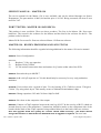
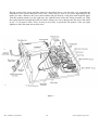
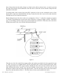
Referring to figure 1 below, lay the monitor-stand on a flat even surface with the front of the unit
facing towards you. Placing your thumbs on the underside of the unit and your fingertips along the
top, pull the plastic front panel towards you and at the same time downwards and away from the
unit. Once the front panel is removed, turn the unit around and remove the back panel in the same
way. The side panels will now pull off the unit using the same technique.
figure 1
Doc. 9990011 April 1987
-9-
Acorn Engineering News
Having removed the front and side panels as described above, turn the unit over and undo the
outermost screws on the underside of the case. (There may be four or six screws depending on the
model you have.) Remove the screws and washers and put them in a safe place until required again.
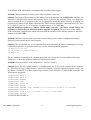
Turn the monitor-stand over (the right-way up) with the front of the unit facing towards you. Slide
the top backwards and pull the main unit clear, taking care not to damage the disc drive data cable
or the +5 volt power cable. Note: It may be necessary to push the side panels of the top apart
slightly to allow the main unit to slide clear.
figure 2
Doc. 9990011 April1987
-10-
Acorn Engineering News
Before fitting the second disc drive it is necessary to remove the existing disc drive data cable and
fit a dual disc drive cable for connection to the second drive.
Carefully turn the unit onto its side, undo the screws holding the cable clamp in position and lift it
free. Unplug the IDC connector from the disc drive and untwist the cable so that it is flat all the
way along. Carefully pull the cable from outside the unit and thread the IDC connector through the
slot in the base of the unit, pulling the cable free.
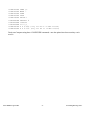
Install the dual drive data cable along the same path used for the single drive cable just removed.
When the new data cable is inserted and pulled through the slot in the base of the unit, it must be
twisted over in order to correctly orientate the DC connectors for connection to the disc drives.
(Refer to figure 3 below).
figure 3
Doc. 9990011 April1987
-11-
Acorn Engineering News
Note: Ensure that the data cable clamp is re-fitted on the cable as shown above, in order to prevent
the cable from snaring on the underside of the disc drive. (Insert the screws into the clamp from the
underside of the unit).
To hold the data cable in place plug in the IDC connector to drive 0 (the existing disc drive). Note
that the IDC connector is polarised and will only fit onto the drive the correct way-round, therefore
it should not be forced onto the connector.
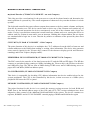
Before fitting the new disc drive it has to be configured as "drive 1" so that the computer recognises
it. Do this by positioning the switch on the side of the drive as shown in figure 4 below. If the drive
type you are fitting is not the same as the one described here (SONY F6 3W) then refer to the drive
setting instructions in the Acorn Dealer Information Manual.
figure 4
Take the new disc drive and fit the support pillars and washers provided in the the upgrade kit onto
it. (Take care not to over-tighten them). Fit the second disc drive in place ensuring the power cable
isn't trapped behind one of the support pillars. Holding the disc drive and case turn the unit onto its
side and align the holes on the case with the threads on the pillars. Insert the screws with
shakeproof washers into the pillars and tighten firmly. Turn the unit back onto its base and connect
the power and data cables to drive 1. (The disc drive you have just installed in the unit).
Doc. 9990011 April1987
-12-
Acorn Engineering News
Re-assemble the unit by reversing the dismantling instructions given above. Note: Ensure that when
the top case is re-fitted the ventilation slots are at the back of the unit.
Now that the upgrade has been completed it is advisable to do a functional test of the new disc
drive. For example, check that discs can be formatted, and also that the drive will write to and read
from discs without errors.
MASTER COMPACT - SONY DISC SERVICE MANUAL
The service manual for the Sony disc drive is now available from the Spares department. Please
note that we will not be supplying spares for this unit, but probably the only simple service that can
be performed on the drives is alignment. Drives that fail that you are unable to service should be
returned to us as complete components. Please return drives to us as quickly as possible if they are
within warranty as we only have a limited warranty with Sony.
MASTER COMPACT - PHILIPS MONITORS SERVICE MANUALS
The service manuals for the Philips monitors is now available from the Spares department. There
are two of these manuals. One for the ADF32 colour monitor, and one for the ADF31 monochrome
monitor. Please note that, like the Sony disc drives, we will not supply spare parts for these
monitors. Should you require spare parts, it may be possible for you to open a spares account with
Philips UK. However, many of the components are standard parts available through normal
electronic component sources.
TUBE ULA - SERVICE INFORMATION
As you are probably aware, we are stopping using the original Ferranti Tube ULA (9C ULA) in
production of turbo boards, and have not used them for 512 co-processor boards. They have been
replaced in this application by a new part, the CMOS tube chip (sometimes known as the AMI tube
chip). This new device can be used as a drop in replacement for the Ferranti ULA for internal Coprocessors, but NOT for external second processors, or ACWs. For external second processors
you should continue to use the Ferranti ULA in servicing, until an emulator board becomes
available allowing the AMI chip to be used in external second processors. The Ferranti chip should
continue to be used for service of ACWs.
Relevant part numbers are:
2201,266
0201,605
CMOS Tube Chip - use in ALL internal co-processors
Ferranti ULA - use in external second processors / ACW
Arrangements for the Bipolar Tube emulator will be made known when we have them available.
These should then be used in external co-processors, but NOT in ACWs (as they will not physically
fit).
Doc. 9990011 April1987
-13-
Acorn Engineering News
REPAIR OF UNITS CONTAINING MODULES
We have noticed in certain instances a tendency to return modules for replacement where a repair
has been completed. In an ET, for example, should a fault develop in the Econet module, we would
expect that you should be able to repair the module to component level, rather than returning the
module to us for replacement. The Spares department, who are responsible for the return of
components used in warranty repairs, do not carry stocks of this board, and replacements will not be
issued in these circumstances. This also applies to the 64k daughter board in a 128k B+. This would
not apply in a situation where an Econet module was fitted to a Master 128 and was found to be
faulty. However, in this case, it should come back complete with the relevant manuals and cables
etc, as a complete product. Similarly the 64k upgrade unit, if supplied as a 64k upgrade kit and
found faulty on arrival, may be returned using the GRA procedure.
GRA - NEW PROCEDURE
We will shortly be introducing a new procedure for the return of goods for both dead on arrival
(DOA) and warranty repair. The situation for goods dead on arrival is similar to the situation that
we have operated up to now, but we will impose a time limit from the date of supply of the goods
beyond which we will not treat the goods as DOA. We shall also require you to furnish us with our
reference number for the supply of the goods. This number appears on both invoices and advice /
delivery notes.
For warranty repair, at Central Workshop, a GRA will also be issued. This procedure is different
from that operated in the past, but allows us to keep better track of failures, and better control on the
flow of repairs. Eventually, this should lead to a significantly faster turnround, and hence more
satisfaction for your customers.
However, for both of these procedures, it is important that the correct paperwork is followed.
Therefore please ensure that before returning goods you have the correct paperwork. To obtain this
paperwork, please contact our Goods Return Co-ordinator, Kay Morris, on Cambridge (0223)
214411.
Doc. 9990011 April1987
-14-
Acorn Engineering News
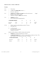
MASTER 128 1770 DFS VERSIONS
Version
2.20
*
First release
2.24
*
*
Loading with OSFILE &FF returns A =1
File saves >64K work
2.25
*
*
*
CLOSE0#and *CLOSE and *SHUT leaves files with correct
Writing to extent works correctly
Unknown command as LIBFS works correctly
2.26
*
*
OSGBPB
2.27/8
length.
speeded-up
All four head step rates implemented i.e.
*CONFIGURE FDRIVE
0
1
2
3
gives for
and for
6
6
12
12
20
2
30 mS
3 mS
1770
1772
*
*
Software patch for spurious Motor-on after 1770 reset,
Following fixed:
If
a) a file was open,
b) the disk had been changed,
c) BREAK was pressed
then the old disk catalogue would be written to the new disk.
2.29
*
*
Doc. 9990011 April1987
OSGBPB
tube problem introduced at 2.26 fixed
*CONFIGURE FDRIVE 2 has software delay added to hardware delay. This
allows support of slow step rate drives with 1772 fitted, ie
*CONFIGURE FDRIVE
0
1
2
3
gives for
and for
6
6
12
12
50
32
30 mS
3 mS
1770
1772
-15-
Acorn Engineering News
UNIVERSAL SECOND PROCESSOR WITH MASTER 128
The Universal Second Processor was developed primarily to permit BBC model B and B+ users to
be able to take advantage of the Co-processors available with the Master 128, ie, Turbo, 512.
The Universal Second Processor is however capable of being used in combination with the Master
128 as well, subject to the following 1.
Turbo
module
- can be contained within either the USP or the Master 128
2.
512
module
- must ONLY be contained within the Master 128 NOT within the USP.
Once a module has been fitted to either the USP or Master 128, it is highly preferable for that
module to remain in that location. The connectors for these modules were not designed for repeated
insertions and damage may occur if such swapping in and out of modules is frequent.
If a customer identifies that despite the above he wishes to use his USP in this way, then the sockets
may be replaced with ZIF sockets at the customers expense, the replacement being undertaken by
qualified personnel, ie, Acorn approved service centres.
MASTER ECONET MODULE - NEW TYPE
The Econet module ADf10 has recently undergone a small design change. This includes the
"Collision Defect" logic found on earlier BBC B network interfaces, but not generally required as
the protocots of Econet ensure adequate handling of network collisions in Software. However some
other network products do not have the facility to detect such problems adequately in software, and
the hardware detect logic has been re-instated to allow use of Masters with these products.
UNIVERSAL ECONET TESTS
A Universal Econet interface test program will shortly be available from the Spares Department.
This requires the Econet test box which was previously only suitable for use with the FIT tester. A
test station is also required, and this should be EITHER a BBC BDE or a Master 128 with a new
style Econet Module.
This software tests Econet interfaces on the following machine types: BBC 'B', B+, Master 128,
ET, Compact, ACW. The part number for this is 0343, 920.
Doc. 9990011 April 1987
-16-
Acorn Engineering News


![[U4.CF.10] Macro commande MACR_ASCOUF_MAIL](http://vs1.manualzilla.com/store/data/006354930_1-d542aea8e5942288575b44a1838d905d-150x150.png)