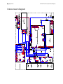
1
CP 150 12-lead resting
electrocardiograph
Service manual
© 2013 Welch Allyn. All rights are reserved. To support the intended use of the product described in this
publication, the purchaser of the product is permitted to copy this publication, for internal distribution
only, from the media provided by Welch Allyn. No other use, reproduction, or distribution of this
publication, or any part of it, is permitted without written permission from Welch Allyn. Welch Allyn
assumes no responsibility for any injury to anyone, or for any illegal or improper use of the product, that
may result from failure to use this product in accordance with the instructions, cautions, warnings, or
statement of intended use published in this manual.
Welch Allyn is a registered trademark of Welch Allyn.
Software in this product is copyright 2013 Welch Allyn. All rights are reserved. The software is protected
by United States of America copyright laws and international treaty provisions applicable worldwide.
Under such laws, the licensee is entitled to use the copy of the software incorporated with this
instrument as intended in the operation of the product in which it is embedded. The software may not be
copied, decompiled, reverse-engineered, disassembled, or otherwise reduced to human-perceivable
form. This is not a sale of the software or any copy of the software; all right, title, and ownership of the
software remain with Welch Allyn.
Welch Allyn Technical Support:
http://www.welchallyn.com/about/company/locations.htm
105323 (printed copy)
Material Number 719489
DIR 80018104 Ver. B
Welch Allyn, Inc.
4341 State Street Road
Skaneateles Falls, NY 13153-0220 USA
www.welchallyn.com
iii
Contents
Symbols ................................................................................................... 1
Safety ....................................................................................................... 5
General warnings ................................................................................................. 5
General cautions .................................................................................................. 7
General safety considerations .............................................................................. 8
Electrostatic discharge (ESD) ............................................................................... 9
Overview ................................................................................................ 11
Purpose and scope ............................................................................................ 11
Technical support services ................................................................................. 11
Service loaners ................................................................................................... 12
Service options .................................................................................................. 12
Repairs ............................................................................................................... 13
Configuration options ......................................................................................... 14
The Welch Allyn Service Tool ............................................................................ 15
Returning products ............................................................................................ 15
Service menu ......................................................................................... 19
Access the Service screen ................................................................................. 19
Performing the full-functional tests .................................................................... 19
Manage tests and other files ............................................................................. 27
Troubleshooting .................................................................................... 29
Symptoms and solutions ................................................................................... 29
Printer ................................................................................................................ 31
User interface .................................................................................................... 33
Post test error messages ................................................................................... 35
Disassembly, repair, and reassembly .................................................. 37
Required tools and equipment ........................................................................... 38
Power down the electrocardiograph .................................................................. 40
Remove the battery ........................................................................................... 40
Separate the top housing assembly from the bottom housing assembly ......... 41
Electrical safety testing ......................................................................... 69
Software updates process .................................................................... 71
Update process .................................................................................................. 71
Export and import of the device configuration ................................................... 72
iv
Contents
CP 150 12-lead resting electrocardiograph
Field replaceable units .......................................................................... 75
Housing top assembly ...................................................................................... 75
Housing base assembly ..................................................................................... 79
Printer 8 inch assembly tray ............................................................................... 82
Bottom assembly ............................................................................................... 86
Partners in Care service and support agreements ............................................. 89
Service and repair training .................................................................................. 89
Appendices ............................................................................................ 91
Decontamination and cleaning requirements .................................................... 91
Interconnect diagram ......................................................................................... 92
1
Symbols
Documentation symbols
WARNING The warning statements in
this manual identify conditions or
practices that could lead to illness, injury,
or death.
Caution The caution statements in this
manual identify conditions or practices
that could result in damage to the
equipment or other property, or loss of
data. This definition applies to both
yellow and black and white symbols.
Consult operating instructions.
Power symbols
Power on/standby
(LED off) No AC power is present
The battery is absent or faulty
(LED green) AC power is present, and
battery is charged. (LED amber) AC power
is present, and battery is charging.
The battery is charged to the indicated
level
Alternating current
Battery is charging
Dangerous voltage
Battery door
Fuse
Rechargeable battery
2
Symbols
CP 150 12-lead resting electrocardiograph
Protective earth
Nonionizing electromagnetic radiation
Equipotential terminal
AC input power
Connectivity symbols
USB
Ethernet (RJ-45 )
Shipping, storing, and environment symbols
This end up
Keep dry
Fragile
Relative humidity limit
Temperature limits
Atmospheric air-pressure limits
Separate the battery from other
disposables for recycling
Recycle
Separate the device from other
disposables for recycling.
China RoHS (restriction of hazardous
substances) symbols for control of
pollution caused by electronic
information products. 5-year
environment-friendly use period (EFUP)
for batteries. 10-year EFUP for the device.
For details, see the accompanying
documentation.
See www.welchallyn.com/weee.
Lithium ion battery
Service manual
Symbols 3
Miscellaneous symbols
Manufacturer
Defibrillation-proof Type CF applied parts
Reference/Model number
Serial number
Reorder/Catalog number
Batch code
Intertek ETL listed
Do not reuse
Electromagnetic compatibility (EMC) information
For information about electromagnetic compatibility (EMC), see the Welch Allyn website.
http://www.welchallyn.com/apps/products/product_category.jsp?catcode=CARDIO
4
Symbols
CP 150 12-lead resting electrocardiograph
5
Safety
All users of the device must read and understand all safety information presented in this
manual before using or repairing the device.
United States federal law restricts this device to sale, distribution, or use by or on the
order of a licensed medical practitioner.
General warnings
Warnings indicate conditions or practices that could lead to illness, injury, or death.
Warnings related to the environment
WARNING The power cord is considered the disconnect device for
isolating this equipment from supply mains. Do not position the equipment
so that it is difficult to reach or disconnect.
WARNING To avoid a possible explosion, do not use the
electrocardiograph in the presence of flammable anesthetics: mixtures
containing air, oxygen, or nitrous oxide.
WARNING When transporting the electrocardiograph on a cart, tuck the
patient cable away to keep them clear of the wheels and to minimize trip
hazards.
Warnings related to accessories and other equipment
WARNING To avoid the risk of electric shock, this equipment must only
be connected to a supply mains with protective earth.
WARNING For operator and patient safety, peripheral equipment and
accessories that can come in direct patient contact must be in compliance
with all appropriate safety, EMC, and regulatory requirements.
WARNING All signal input and output (I/O) connectors are intended for
connection of only devices complying with IEC 60601-1, or other IEC
standards (for example, IEC 60950), as appropriate to the device.
Connecting additional devices to the electrocardiograph might increase
chassis or patient leakage currents.
6
Safety
CP 150 12-lead resting electrocardiograph
WARNING The electrocardiograph has not been designed for use with
high-frequency (HF) surgical equipment and does not protect against
hazards to the patient.
WARNING Defective batteries can damage the electrocardiograph.
Visually inspect the battery at least monthly, if the battery shows any signs
of damage or cracking, it must be replaced immediately and only with a
battery approved by Welch Allyn.
WARNING Improper disposal of batteries may create an explosion or
contamination hazard. Never dispose of batteries in refuse containers.
Always recycle batteries according to local regulations.
WARNING All signal input and output (SIP/SOP) connectors should not be
contacted by patient directly and indirectly through the user during
operation.
Warnings related to using the electrocardiograph
WARNING No modification of this equipment is allowed.
WARNING This device captures and presents data reflecting a patient’s
physiological condition. When reviewed by a trained physician or clinician,
this data can be useful in determining a diagnosis. However, the data
should not be used as a sole means for determining a patient’s diagnosis or
prescribing treatment.
WARNING To provide CF protection use only accessories approved by
Welch Allyn. Visit www.welchallyn.com. The use of any other accessories
can result in inaccurate patient data, can damage the equipment, and can
void your product warranty.
WARNING To avoid serious injury or death, take these precautions during
patient defibrillation:
•
Avoid contact with the electrocardiograph, patient cable, and patient.
•
Verify that the patient leads are properly connected.
•
Place defibrillator paddles properly in relation to electrodes.
•
After defibrillation, pull each patient lead out of the patient cable and inspect
the tips for charring (black carbon marks). If there is any charring, the patient
cable and individual leads must be replaced. If there is no charring, fully
reinsert the leads into the patient cable. (Charring can occur only if a lead is
not fully inserted into the patient cable before defibrillation.)
WARNING To prevent the spread of infection, take these precautions:
•
Dispose of single-use components (for example, electrodes) after using
them once.
•
Regularly clean all components that come in contact with patients.
•
Avoid ECG testing for patients with open, infectious sores.
WARNING Avoid positioning any leads or cables so that they could easily
trip someone or become wrapped around a patient’s neck.
Service manual
Safety
7
WARNING To ensure safe use of the device, follow the documented
maintenance procedures.
WARNING Only qualified service personnel should attempt to repair the
electrocardiograph. In case of a malfunction, call Technical Support.
WARNING Do not perform ST segment analysis on the ECG screen
display, since these ECG representations are scaled. Make manual
measurements of ECG intervals and magnitudes on printed ECG reports
only.
WARNING To maintain diagnostic accuracy and to comply with IEC
60601-02-51 and IEC 60601-02-25, do not scale (re size) when sending a
saved ECG to an external printer.
WARNING To avoid injury, do not touch the print head immediately after
printing. It might be hot.
General cautions
Cautions indicate conditions or practices that could damage the equipment or other
property.
CAUTION When removing the electrocardiograph from storage, allow it to
thermally stabilize to surrounding environmental conditions before using it.
CAUTION To prevent possible damage, do not use sharp or hard objects
to press the touch screen or the buttons. Only use fingertips.
CAUTION Do not expose the patient cable to strong ultraviolet radiation.
CAUTION Do not pull or stretch the patient cable. Doing so could result in
mechanical or electrical failures. Form the patient cable into a loose loop
before storing.
CAUTION Avoid positioning the patient cable where it might get pinched,
stretched, or stepped on. Otherwise, measurements might no longer be
accurate, and repair might be necessary.
CAUTION Using the equipotential terminal for anything but grounding
purposes may contribute to damage of the device.
CAUTION Use only parts and accessories, including thermal paper, that
were supplied with the device and available through Welch Allyn. The use
of accessories other than those specified may result in degraded
performance or unsafe use of this device.
CAUTION Portable and mobile RF communications equipment can affect
the performance of the electrocardiograph.
CAUTION The electrocardiograph meets the Class A requirements of IEC
60601-1-2 regarding incidental emission of radio frequency interference. As
such it is suitable for use in commercial grade electrical environments. If
the electrocardiograph is used in residential grade electrical environments
and you experience incidental interference with other equipment that uses
radio frequency signals to operate, minimize the interference.
8 Safety
CP 150 12-lead resting electrocardiograph
CAUTION Other medical equipment—including but not limited to
defibrillators, ultrasound machines, pacemakers, and other stimulators—
may be used simultaneously with the electrocardiograph. However, such
devices may disturb the electrocardiograph signal.
CAUTION The power cord must be disconnected from AC power before
cleaning, maintaining, transporting, or servicing.
CAUTION The requirements of AAMI EC11, Section 3.2.7.2, Frequency
and Impulse Response, for an impulse triangle waveform may be impacted
by up to 5 milliseconds of small amplitude dampened ringing immediately
after the impulse when the muscle filter (35 Hz) is turned on or a small
amplitude offset when the baseline filter (0.5 Hz) is turned on. These filters,
in any combination turned on or off, meet the AAMI requirements.
Measurements performed by the optional interpretation algorithm are
unaffected by any filter selections.
Note
The entire patient cable, up to and including the electrodes are considered
to be an Applied Part.
General safety considerations
•
To ensure patient safety, use only accessories recommended or supplied by Welch
Allyn. Always use accessories according to your facility’s standards and according to
the manufacturer’s recommendations and instructions. Always follow the
manufacturer’s directions for use.
•
Welch Allyn recommends that only Welch Allyn service personnel or an authorized
repair center perform warranty service. Performing unauthorized service on a device
that is within warranty may void the warranty.
Service manual
Safety
9
Electrostatic discharge (ESD)
CAUTION Electrostatic discharge (ESD) can damage or destroy electronic
components. Handle static-sensitive components only at static-safe
workstation.
CAUTION Assume that all electrical and electronic components of the
device are static-sensitive.
Electrostatic discharge is a sudden current flowing from a charged object to another
object or to ground. Electrostatic charges can accumulate on common items such as
foam drinking cups, cellophane tape, synthetic clothing, untreated foam packaging
material, and untreated plastic bags and work folders, to name only a few.
Electronic components and assemblies, if not properly protected against ESD, can be
permanently damaged or destroyed when near or in contact with electrostatically
charged objects. When you handle components or assemblies that are not in protective
bags and you are not sure whether they are static-sensitive, assume that they are staticsensitive and handle them accordingly.
•
Perform all service procedures in a static-protected environment. Always use
techniques and equipment designed to protect personnel and equipment from
electrostatic discharge.
•
Remove static-sensitive components and assemblies from their static-shielding bags
only at static-safe workstations—a properly grounded table and grounded floor mat—
and only when you are wearing a grounded wrist strap (with a resistor of at least 1
megohm in series) or other grounding device.
•
Use only grounded tools when inserting, adjusting, or removing static-sensitive
components and assemblies.
•
Remove or insert static-sensitive components and assemblies only with device
power turned off.
•
Insert and seal static-sensitive components and assemblies into their original staticshielding bags before removing them from static-protected areas.
•
Always test your ground strap, bench mat, conductive work surface, and ground
cord before removing components and assemblies from their protective bags and
before beginning any disassembly or assembly procedures.
10
Safety
CP 150 12-lead resting electrocardiograph
11
Overview
Purpose and scope
The purpose of this manual is to assist with some common troubleshooting scenarios
you may encounter and to explain the export, import, update and upgrade process. It is
intended for use only by trained and qualified service personnel.
Corrective service is supported to the level of field-replaceable units. These include
circuit-board assemblies and some subassemblies, case parts, and other parts.
WARNING When performing a service procedure, follow the instructions
exactly as presented in this manual. Failure to do so could damage the
device, invalidate the product warranty, and lead to serious personal injury.
CAUTION No component-level repair of circuit boards and subassemblies
is supported. Use only the repair procedures described in this manual.
Find instructions for functional testing and performance verification in the Welch Allyn
Service Tool help files (http://www.welchallyn.com/promotions/services/
serviceTool.htm.)
This manual applies only to this device. For servicing of any other device, see the service
manual for the specific device.
Service work not described in this manual must be performed by qualified service
personnel at the factory or at an authorized Welch Allyn service center.
Related documents
When using this manual, refer to the following:
•
Welch Allyn CP 150 12-lead resting electrocardiograph Directions for use (part
number 105313)
•
Welch Allyn Service Tool Install guide (part number 103820)
•
Welch Allyn website: www.welchallyn.com
Technical support services
Welch Allyn offers the following technical support services:
•
Telephone support
12 Overview
CP 150 12-lead resting electrocardiograph
•
Loaner equipment
•
Service Agreements
•
Service training
•
Replacement service parts
•
Product service
For information on any of these services, contact the Welch Allyn Service Center nearest
you.
Service loaners
For warranty or non-warranty repairs not covered under a support agreement, loaners are
available for a nominal charge, subject to availability. Payment is required prior to
shipment for all loaners not covered under a support agreement. The loaner fee can be
found on the Welch Allyn loaner price list.
Welch Allyn Service Centers that provide repair service for this product can, on request,
loan a device for use while the device is being repaired. Loaned devices are provided
free of charge for products repaired while under a support agreement that includes a
free loaner provision.
Loaner equipment for the individual component modules is not available.
Service options
Partners in Care service agreements
While product warranties provide basic assurance of Welch Allyn hardware quality, they
may not include the full range of services and support you need. Welch Allyn offers
premium service and support through our Partners in Care program. Whether you
service your own devices and require a minimum of support or rely on us to service your
device, Welch Allyn provides a program that will meet your needs. For more information
visit our web site at www.welchallyn.com or call your sales representative.
Warranty service
All repairs on products under warranty must be performed or approved by Welch Allyn.
Refer all warranty service to Welch Allyn Product Service or another authorized Welch
Allyn Service Center. Obtain a Return Material Authorization (RMA) number for all returns
to Welch Allyn Product Service.
CAUTION Unauthorized repairs will void the product warranty.
Non-warranty service
Welch Allyn product service and authorized service centers support non-warranty repairs.
Contact any Welch Allyn regional service center for pricing and service options.
Welch Allyn offers modular repair parts for sale to support non-warranty service. This
service must be performed only by qualified end-user biomedical/clinical engineers using
this service manual.
Service manual
Overview 13
Repairs
A Welch Allyn Service Center must perform all repairs on products under warranty,
unless you have purchased a Welch Allyn support agreement allowing you to service the
device while under warranty.
CAUTION Unauthorized repairs will void the product warranty.
Qualified service personnel or a Welch Allyn Service Center should repair products out of
warranty.
If you are advised to return a product to Welch Allyn for repair or routine maintenance,
schedule the repair with the service center nearest you.
Welch Allyn Technical Support
If you have a problem with the device that you cannot resolve, call the Welch Allyn
Technical Support Center nearest you for assistance. A representative will assist you in
troubleshooting the problem and will make every effort to solve the problem over the
phone, avoiding a potential unnecessary return.
If your product requires warranty or non-warranty repair service, a Welch Allyn Technical
Support representative will record all necessary information to issue an RMA number.
The support representative will provide you with the address of the Welch Allyn Service
Center to send your device to.
An RMA number must be obtained prior to any return. Be sure to note this number on
the outside of your shipping box and include a copy of the RMA in the box.
Returns without an RMA number will not be accepted for delivery.
Technical support is available during local business hours.
14 Overview
CP 150 12-lead resting electrocardiograph
Configuration options
Model
Accessories
Language
Power cord
CP150
1 - AHA, disposable
EN - English
2 - Europe
A - Interpretation
2 - IEC, disposable
FR - French
3 - Israel
None
3 - AHA, reusable
DE - German
4 - UK
4 - IEC, reusable
ES - Spanish
5 - Switzerland
NL - Dutch
66 - Australia
BP - Brazilian
Portuguese
7 - S. Africa
PT - Portuguese
B - North America
ZH - Simplified
Chinese
C - China
RU - Russian
G – Argentina
NO - Norwegian
N – India/UAE
SV - Swedish
Z - Brazil
Examples: CP150-1ENB, CP150A-1ENB, CP150A-4DE5
Service manual
Overview
15
The Welch Allyn Service Tool
The Welch Allyn Service Tool is available in the Silver edition. Download from Welch
Allyn website.
Clinicians and technical service personnel can use the service tool to manage and
maintain supported Welch Allyn products. You can use the service tool to do the
following:
•
Review device information. When connected to the device, the service tool lists
installed modules, installed firmware and hardware versions, warranty and repair
information, status, and usage history.
•
Receive notifications when periodic maintenance is needed. The service tool can
help you manage and maintain your entire inventory of supported Welch Allyn
products. Through the remote service function, the service tool can connect to
Welch Allyn Customer Service. With this functionality you can automatically receive
firmware updates and feature upgrades for your supported products, including
software upgrades for the service tool.
•
Install updates. The service tool can read the firmware version of the CP 150 and
check for available updates or upgrades.
•
Install upgrades. An interpretation option is available for purchase. The CP 150
basic can be upgraded to a CP 150A (with the Interpretation option) through the
Welch Allyn Service Tool.
•
Create a work list. The work list provides information about service actions—
referred to as work orders—that are waiting for you to perform on your maintained
devices. Work orders may include periodic calibrations, upgrades, or license
installations.
•
Schedule periodic maintenance. You can use the service tool to set the service
interval for each maintained device.
•
View and save logs. You can download and save log files from the device for
analysis to help diagnose and identify reported issues.
•
Create user accounts. Administrators can create user accounts and set permission
levels to control access to the features, allowing one group to perform administrative
tasks and another to perform service tasks. Restricting access prevents the service
tool from being used to make unauthorized changes on a connected device.
•
Perform functional verification. The service tool can be used to test the device to
ensure that it meets performance specifications.
•
Recover devices. In the rare case where a device can no longer boot because of
corrupted firmware, the service tool can connect the device to Welch Allyn Technical
Support to reinstall the firmware.
•
Extensible. The device accepts new plug-ins to support future Welch Allyn products.
Returning products
When returning a product to Welch Allyn for service, ensure that you have the following
information:
•
Product name, model number, and serial number. This information may be found on
the product and serial number labels on the bottom of the device.
•
A complete return shipping address.
•
A contact name and phone number.
16
Overview
CP 150 12-lead resting electrocardiograph
•
Any special shipping instructions.
•
A purchase-order number or credit-card number if the product is not covered by a
warranty.
•
A full description of the problem or service request.
1. Contact Welch Allyn and request an RMA number.
Welch Allyn does not accept returned products without an
RMA.
Note
2. Ship the device to Welch Allyn, observing these packing guidelines:
a.
Remove from the package the battery, all hoses, connectors, cables, sensors,
power cords, and other ancillary products and equipment, except those items
that might be associated with the problem.
Recommendations for returning the Lithium Ion battery
•
Use ground transportation to return batteries.
•
If returning multiple batteries, package each battery individually.
•
Do not consolidate multiple batteries in a single package.
•
Use packaging provided by Welch Allyn or the battery manufacturer.
•
Do not pack a defective battery in checked or carry-on baggage if traveling
by air.
Packaging
•
If you return the battery with the device, remove the battery, seal the battery
in an antistatic plastic bag, and place the battery in the position reserved for
the battery in the original shipping carton near the device.
•
If you return the battery separately, package the battery in the replacement
battery’s plastic bag and shipping box.
If the original shipping carton or replacement battery shipping box is unavailable,
consult the manufacturer website for information regarding shipping lithium ion
batteries:
www.nexergy.com/lithium-shipping.htm
WARNING Safety risk. Do not ship any battery that has
been physically damaged or shows signs of leakage
unless you receive specific instructions which meet the
requirements for the shipment of Lithium batteries.
Dispose of damaged or leaking batteries in an
environmentally safe manner consistent with local
regulations.
Note
In the United States, the applicable regulations can be
found in the Code of Federal Regulations (CFR). Refer to
49 CFR 173.185 for shipping lithium batteries by air or
ground. Use 49 CFR 172.102 sections 29, 188, 189, A54,
A55, A100, A101, A103, and A104 to find the special
provisions for shipping lithium batteries.
b. Clean the device.
Service manual
Overview 17
Note
c.
To ensure safe receipt of your device by the service
center and to expedite processing and return of the
device to you, thoroughly clean all residues from the
device before you ship it to Welch Allyn. For
decontamination and cleaning requirements, see
“Decontamination and cleaning” in the appendices.
If a returned device is found to be contaminated with
bodily fluids, it will be returned at the owner’s expense.
United States federal regulations prohibit the processing
of any device contaminated with blood-borne pathogens.
Welch Allyn thoroughly cleans all returned devices on
receipt, but any device that cannot be adequately
cleaned cannot be repaired.
Put the device, enclosed in a plastic bag with a packing list, into the original
shipping carton with the original packing materials or into another appropriate
shipping carton.
d. Write the Welch Allyn RMA number with the Welch Allyn address on the outside
of the shipping carton.
18
Overview
CP 150 12-lead resting electrocardiograph
19
Service menu
Access the Service screen
Note
The service menu ID and password are based on a telephone keypad.
ID: 7378423 (=SERVICE)
PASSWORD: 6676737 (=NORMSER)
1. From the ECG home tab, touch the Settings tab. The ECG tab and the vertical ECG
configuration tab appear.
2. Touch the Service tab.
3. Enter 7378423 as the User ID code and touch the OK button.
4. Enter 6676737 as the Password and touch the OK button.
5. Touch the OK button again.
6. When you are done, touch
.
The ECG home tab appears.
Performing the full-functional tests
Complete the full-functional CP 150 tests to verify device functionality.
Note
If any of the tests fail, contact Technical Support.
The following off-the-shelf tools are required to complete the functional verification tests:
•
Standard ECG Patient Simulator (example: Model 430B, Medi Cal Instrument, Inc. or
equivalent)
•
USB Cable (Type A (M) connector to mini-B (M) connector)
•
Standard USB Thumb drive (256M to 64Gb, recommend 2 Gb)
•
2 RJ45 Ethernet cables (less than 3 M in length)
With the Service tab open, touch the CP 150 button to perform a hardware test.
20
Service menu
CP 150 12-lead resting electrocardiograph
Battery test
Note
Ensure that the battery is installed and has been charged for a minimum of
four hours before preforming this test.
1. If the Battery remaining field shows 70% or less, replace the battery.
2. Touch the
(Next) button to perform the next functional test.
Audio test
1. Touch the
button to play the audio sample.
2. Touch the Yes button if you are able to hear the sound, or touch the No button if you
are not able to hear the sound.
3. Touch the
(Next) button to perform the next functional test.
Service manual
Service menu
USB host test
Note
Welch Allyn has not validated specific USB flash drives. Use only 64Gb or
less USB flash drives.
1. Insert a USB flash drive into each of the four ports on the back of the device and
follow the instructions on the screen to test each of the ports.
2. Touch the USB host test button to test each port from left to right.
3. Touch the
(Next) button to perform the next functional test.
USB client test
1. Connect a USB type mini-B connector to the device client USB port and a type A
connector to a free USB port on the PC. Verify that the PC is able to recognize
CP150 device.
2. Touch the Yes button to confirm that your PC recognized the CP 150 device, or
touch the No button if your PC did not recognized the CP 150 device.
3. Touch the
(Next) button to perform the next functional test.
21
22
Service menu
CP 150 12-lead resting electrocardiograph
Keypad test
button on the device to check the On/Off keypad. "Pass" is indicated
1. Press the
with a √ (check mark) and "fail" is indicated with an X.
2. Touch the
(Next) button to perform the next functional test.
Service manual
Service menu
ECG lead test
1. Connect a set of known good Patient Cables, with leads, to an ECG simulator.
Note
Any yellow dots on the lead-status screen indicate
unattached or poorly attached leads.
2. Verify the lead placement on the screen by observing that all leads appear green.
3. Touch the
(Next) button to perform the next functional test.
23
24
Service menu
CP 150 12-lead resting electrocardiograph
Printer pattern test
1. Touch the Print button to print a test page.
2. Use the specifications in the Print verification checklist table and the Printer pattern
test and check point graphic to verify the correct operation of the device printer by
comparing the pattern printed on the test page.
Print verification checklist
Point
Description
Point A
Verify the distance of the arc on the circle from the top edge of the paper is
11 mm +/- 3 mm
Point B
Verify the distance of the arc on the circle from the left edge of the paper is
50 mm +/- 5 mm
Point C
Verify that the line is straight and without breaks from top to bottom
Point D
Verify that the thick black line is uniform in blackness without breaks from
top to bottom
Point E
Verify the print is readable
Point F
Verify line is straight and measures 100 mm +/ -5 mm
Service manual
Service menu
25
Printer pattern test and check point
3. Touch the Yes button if the test page printed correctly, or touch the No button if the
test page did not print correctly.
4. Touch the
(Next) button to perform the next functional test.
Printer speed test
1. Touch each of the 10 mm/s, 25 mm/s, and 50 mm/s buttons to print a test page.
2. Use the speed test print page to verify the correct operation of the device printer by
comparing the pattern printed on the test page to point F in the Printer speed test
and check point graphic. The line should be a straight line that measures 100 mm
(+/-5 mm).
Printer speed test and check point
3. Touch the Yes button if the test page printed correctly, or touch the No button if the
test page did not print correctly.
4. Touch the
(Next) button to perform the next functional test.
26
Service menu
CP 150 12-lead resting electrocardiograph
Ping test
1. Use an ethernet cable to connect the device to a known network and setup the CP
150 DHCP. (Refer to the CP 150 DFU for setup instructions.) Under the Host
address, enter the IP of a PC connected to the network. Touch the Ping test button
to perform the test.
2. Touch the
(Next) button to exit the functional test.
Test results
Note
If any of the tests fail, contact Technical Support.
Service manual
Service menu
27
Manage tests and other files
Tests:
Button
Feature
Tests + Print
Prints the patient list from the internal memory of the CP
150
Tests + Delete
Deletes the patient test list from the internal memory of the
CP 150
Tests + Send
Sends the patient test list to a USB flash drive
Tests + Import
Imports the patient test list from a USB flash drive
Logs:
Button
Feature
Log + Delete
Deletes the log file
Log + Send
Sends the log file to a USB flash drive
28
Service menu
CP 150 12-lead resting electrocardiograph
29
Troubleshooting
Complete the full-functional tests prior to troubleshooting the CP 150 device
This section provides the following tables to help you troubleshoot the device.
•
Symptoms and solutions
○ System problems
○
Printer problems
○
User interface problems
○
Post test error messages
These tables list symptoms you might observe, list possible causes, and suggest actions
that might eliminate the problem. These tables can help you diagnose and fix a problem.
They do not replace basic troubleshooting skills. You must still trace the source of the
problem to the board or module level to decide the best course of action.
Welch Allyn does not support component-level repair to the board or module.
For available replacement parts, see Field Replaceable Units.
WARNING Do not perform troubleshooting on a device that is emitting
smoke or exhibits other signs of excessive overheating. Disconnect the
device from AC power and call Welch Allyn Technical Support immediately.
CAUTION Replace parts, components, or accessories only with parts
supplied or approved by Welch Allyn. The use of any other parts can lead to
inferior performance and will void the product warranty.
Symptoms and solutions
System problems:
Complete the full functional tests prior to troubleshooting the CP150 electrocardiograph.
Symptom
Possible cause
The electrocardiograph does not power There is no AC power
up when it is plugged into AC power
and the AC power LED is not lit
AC fuse is blown
Suggested action
Check the AC fuses.
Check the AC fuse.
30
Troubleshooting
Symptom
CP 150 12-lead resting electrocardiograph
Possible cause
Suggested action
Loose, disconnected, or faulty switch
power flex
Reseat or replace the switch power
flex.
Faulty or disconnected 60W power
supply
Reseat or replaced the harness power
supply PSU-BAT-SMB-PRT-SMCE.
Replace the 60W power supply.
The electrocardiograph does not power LCD screen is faulty
up when it is plugged into AC power
and the AC power LED is lit
Loose or faulty flex SMCE-LCD
Replace the 7 inch display assembly.
Reseat the flex SMCE-LCD at SMCE or
replace the flex SMCE-LCD.
I/O board harness has a loose
connection or is faulty
Reseat or replace the I/O harness.
I/O board is faulty
Replace the I/O board.
The electrocardiograph does not power The battery power is low
up when it is unplugged
The battery is disconnected
Charge the battery.
Check the battery connections.
The battery is not charging, is depleted, Replace the battery.
or is faulty
The battery will not charge or the
Faulty battery
battery status displays a disconnected
battery
Damaged pins on the battery
connection point
Smart bus harness has a loose
connection or is faulty
Replace the battery.
Replace the battery case assembly.
Reseat or replace the harness.
When connected to AC power and with Faulty battery
the battery installed, the battery status
displays a faulty battery
Replace the battery.
The electrocardiograph prints fewer
The battery is degraded
than 10 reports on a full battery charge
Replace the battery.
While powered-on, the
electrocardiograph does not respond
when you touch the screen
The electrocardiograph cannot perform Reset the electrocardiograph by
an immediate action because the
pressing and holding the power button
software is unresponsive.
for at least six seconds until the screen
goes blank. Press the power button
again to restart.
Note: The electrocardiograph will go
through some diagnostic tests that will
cause it to take longer than usual to
power up.
Off-colored display
Loose or faulty flex SMCE-LCD
Reseat the flex SMCE-LCD at the
SMCE or replace the flex SMCE-LCD.
Faulty LCD display assembly
Replace the 7 inch display assembly.
Service manual
Troubleshooting
Symptom
Possible cause
Suggested action
No response when LCD screen is
touched
Loose or faulty flex SMCE-LCD
Reseat the flex SMCE-LCD at the
SMCE or replace the flex SMCE-LCD.
Faulty LCD display assembly
Replace the 7 inch display assembly.
Local network problem
Verify working network connection.
The communication board is
disconnected
Reseat the communication board
connection.
Unable to obtain a valid IP address
when DHCP is turned on
Incorrect waveform while connected to Faulty patient cable
a simulator
Loose ECG harness
31
Replace the patient cable.
Reseat the ECG harness.
Faulty ECG board
Replace the ECG board.
Faulty patient cable
Replace the patient cable.
Loose ECG harness
Reseat the ECG harness.
Faulty ECG board
Replace the ECG board.
Symptom
Possible cause
Suggested action
The paper does not feed
The paper is jammed
Reload the paper.
Lost communication
Reseat the printer harness.
The printer door is open
Close the printer door.
The door sensor is faulty
Replace the door sensor.
The motor is faulty
Replace the motor.
The motor gear is faulty
Replace the gear assembly.
Lost communication
Reseat or replace the printer harness.
Faulty print head
Replace the print head assembly.
Error loading the paper
Check to ensure that the printer door is
fully closed.
Check the orientation of the paper.
All leads showing off
Printer
Printer problems:
The paper is blank
The wrong type of paper is being used Use only Welch Allyn approved paper.
32
Troubleshooting
CP 150 12-lead resting electrocardiograph
Symptom
Possible cause
Suggested action
The electrocardiograph shuts down
during printing when in battery mode
The battery is low or faulty
Recharge or replace the battery.
Printing is not clear or is garbled
Foreign particles on the printer heating Clean the heating element of the
element
printer to remove any foreign particles.
Apply isopropyl alcohol to a cotton
swab and wipe off the heating element
surface. Allow to dry completely.
Faulty print head
Replace the print head assembly.
Loose platent roller
Reseat the platent roller on the paper
tray assembly.
Check the platent roller catch for a
crack. If a crack is found, replace the
paper tray assembly.
Door open message even when door is Loose door sensor harness connection Reseat door sensor harness connector.
closed
Faulty door sensor
Replace door sensor.
Grinding sound in the gear
Missing dowel pin on one side of the
paper tray assembly
Replace paper tray assembly.
Wear of the gear assembly
Replace gear assembly.
Presence of a foreign object in the
teeth of the gear
Clean and remove foreign object from
the gear assembly.
Service manual
Troubleshooting
33
User interface
User interface problems:
Symptom
Possible cause
Battery is critically low. Shutting
down...
Device automatically shuts down when it reaches If you are unable to charge the
the shutdown capacity. This prevents file system battery, replace the battery.
corruption. (May lose the last unsaved test.)
ECG front-end microprocessor
board error. Contact Technical
Support.
ECG Front End detects CPLD Voltage error which
indicates that any ECG data received from it is
invalid. The Front End will notify the
microcompute engine and will display this error.
When the error is acknowledged, the device will
shutdown.
Check connection to the ECG
board. If connection is okay,
replace ECG board. If the ECG
front end error is still received,
replace the small microcompute
engine board.
Export/Import unsuccessful
Faulty communication module
Replace I/O board.
Loose or faulty I/O harness
Reseat or replace I/O harness.
USB flash drive is at wrong port
Insert flash drive at correct port
and try again.
Faulty Small microcompute engine
Replace small microcompute
engine.
The printer error includes the following:
1. RAM error.
2. Print head temperature above 70°C (replace
printer FSS).
3. Flash memory error.
Check communication between
the printer board and
communication board.
If the board tries to communicate
with the printer and the printer
responds with an error message,
then complete a printer
functional test to ensure printer
is operating properly.
Internal printer error. Contact
Technical Support.
Suggested action
Check harnesses on printer to
see if they are loose.
If problem persists, replace the
print head assembly and printer
board.
Internal printer is overheated. Try
to print again after 10 minutes to
let the printer cool down.
Extended printing has caused the print head to
overheat.
If printing at a high speed for an
extended period of time, the
printer will overheat and will
notify the small microcompute
engine board that it is
overheating and needs to stop
and cool down.
Contact Technical Support if
printer displays this message
when high-speed printing has not
taken place.
34
Troubleshooting
CP 150 12-lead resting electrocardiograph
Symptom
Possible cause
Suggested action
The read-back file is corrupted.
During the Service USB Host test, the content
read back from file does not match the content
previously written.
Ensure that the thumb drive and
port are working properly. If
using another thumb drive results
in the same error, contact
Technical Support.
Internal printer is out of paper.
Reload.
The cue marker on the paper sensor is causing
the printer to incorrectly identify that paper tray
is empty.
Check Que Sensor board and
harness.
Service manual
Troubleshooting
35
Post test error messages
Post test error messages:
Symptom
Possible cause
Suggested action
System Fault code 0x01 Battery capacity is at critical capacity and auxiliary Ensure that AC power is plugged in.
power is not present
Check for faulty battery and/or 60W
power supply.
Check all harness to power supply.
System Fault code 0x02 Core image verification fails
Reload software through the Welch Allyn
Service Tool.
System Fault code 0x03 Core image is missing
Reload software through the Welch Allyn
Service Tool.
System Fault code 0x04 Software update failure
Reload software through the Welch Allyn
Service Tool.
System Fault code 0x05 RAM Test failure
Check for faulty SMCE board.
36
Troubleshooting
CP 150 12-lead resting electrocardiograph
37
Disassembly, repair, and reassembly
These procedures provide instructions for system disassembly and board removal.
Except where otherwise noted, the assembly procedure is the reverse of the
disassembly procedure.
Each procedure may include the following:
•
Reassembly notes: This contains information specific to reassembly not addressed
in the disassembly instructions.
WARNING Electrical shock hazard. Disconnect power before opening the
device.
CAUTION Before disassembling the device, disconnect the AC power
cord and any attached accessories.
CAUTION Perform all repair procedures at a static-protected station.
CAUTION When the system case is opened, regard all parts as extremely
fragile. Execute all procedure steps with care and precision.
CAUTION Observe screw torque specifications, especially with screws
that secure directly into plastic standoffs.
CAUTION To avoid mismatching screws and holes, keep the screws for
each piece with that piece as you remove modules and circuit assemblies.
38
Disassembly, repair, and reassembly
CP 150 12-lead resting electrocardiograph
CP 150 Disassembly Flow chart
Required tools and equipment
•
#1 Phillips bit
•
#2 Phillips bit
•
#10 Torx bit
•
3/16" Hex Socket
•
1/4" Hex Socket
•
Torque driver calibrated for 3.5 in-lb ±0.5 in-lb
•
Torque driver calibrated for 4.0 in-lb ±0.5 in-lb
•
Torque driver calibrated for 5.0 in-lb ±0.5 in-lb
•
Tie-wrap cutter
Note
The torque specifications are only applicable for the assembly processes.
Tools and torque value used during reassembly of Main Unit:
Part Number Description
Torque
Specification
Bit/Socket Type
713017
Shoulder Screw, EAR G-411-1 Metric
5 +/- 0.5 in-lbs.
PH2
106124-34
Screw 4-20 .375 Pan Phillips
5 +/- 0.5 in-lbs.
PH1
Service manual
Disassembly, repair, and reassembly
Part Number Description
Torque
Specification
Bit/Socket Type
713016
Screw, M3 x 5 Pan Head
5 +/- 0.5 in-lbs.
PH1
761077-1
Wire Tie
INT
N/A
713031
Screw, M4 X 10 Pan Head
5 +/- 0.5 in-lbs.
PH2
716960
Shoulder Screw M3 PHD
2 +/- 0.5 in-lbs.
PH1
Tools and torque value used during reassembly of Printer Assembly:
Part Number Description
Torque
Specification
Bit/Socket Type
703246
Screw, M3 X 0.5, Pan Phillips
5 +/- 0.5 in-lbs.
PH1
700118
Shoulder Screw M3 X .5
4 +/- 0.5 in-lbs.
3/16” Hex Socket
106137-1
Nut,4-40X.250 Hex, KEPS Extlock
3.5 +/- 0.5 in-lbs.
1/4" Hex Socket
703258
Screw M3 X 6 PHP FH
5 +/- 0.5 in-lbs.
PH1
106124-34
4-20 0.375 Pan Head Screw
5 +/- 0.5 in-lbs.
PH1
713015
4-20x.5 Pan Head Plastite Screw
5 +/- 0.5 in-lbs.
T10
761077-1
Wire Tie
INT
N/A
39
40
Disassembly, repair, and reassembly
CP 150 12-lead resting electrocardiograph
Power down the electrocardiograph
1. Press and hold the
electrocardiograph.
2. Remove the power supply.
Remove the battery
button for 6-8 seconds to shut down the
Service manual
Disassembly, repair, and reassembly
Separate the top housing assembly from the bottom
housing assembly
1. Turn the electrocardiograph over to access the bottom housing assembly.
2. Remove the eight M4x10 screws from the bottom housing assembly using a #2
Phillips bit.
3. Turn the electrocardiograph over again to access the top housing assembly.
4. Lift up the top housing assembly to access the printer board.
5. Unhook the harness cables from the printer top assembly.
6. Disconnect the harness cable at J16 from the small-medium compute engine
(SMCE) board.
41
42
Disassembly, repair, and reassembly
CP 150 12-lead resting electrocardiograph
7. Cut the wire tie on the EMC ferrite.
8. Disconnect the CN202 connector from the printer board.
9. Disconnect the three harness cables at J8, J17, and J10 from the small-medium
compute engine (SMCE) board.
10. Lift off the top housing and set aside for reuse during reassembly.
Service manual
Disassembly, repair, and reassembly
Reassembly note
•
Use a #2 Phillips bit and a Torque driver calibrated to 5.0 in-lb ± 0.5 in-lb to secure
the bottom housing screws.
Cable identification for reassembly:
43
44
Disassembly, repair, and reassembly
CP 150 12-lead resting electrocardiograph
Top housing disassembly
These procedures provide instructions for system disassembly and board removal.
Except where otherwise noted, the assembly procedure is the reverse of the
disassembly procedure.
Remove the Input/Output (I/O) communication board
•
Separate the top housing assembly from the bottom housing assembly as described.
1. Cut the wire tie on the ECG ferrite and the two wire ties on the EMC harness
ferrites.
Service manual
Disassembly, repair, and reassembly
45
2. Disconnect the J7 and J15 connectors from the SMCE board.
3. Disconnect the WA7 connector from the display assembly.
4. Remove the four 4-20 self-tapping screws from the I/O board using a #1 Phillips bit.
46
Disassembly, repair, and reassembly
CP 150 12-lead resting electrocardiograph
5. Disconnect the three harness cables at CN201, CN203, and CN202 from the I/O
board and remove the harnesses.
Note
Set the harness cables aside for reuse during reassembly.
Reassembly note
•
Use a #1 Phillips bit and a Torque driver calibrated to 5.0 in-lb ± 0.5 in-lb to secure
the SMCE board screws.
SMCE I/O harness cable connection for reassembly:
Note
Ensure that the twisted white wires of the J15 SMCE I/O harness face the
center of the SMCE board so that the pins line up correctly.
Service manual
Disassembly, repair, and reassembly
47
Remove the SMCE board
•
Separate the top housing assembly from the bottom housing assembly as described.
1. Lift up the latch of the J18 connector on the SMCE board and disconnect the flex
cable.
2. Gently pull up on the locking tab latch of the J6 connector on SMCE board and slide
out the flex cable.
48 Disassembly, repair, and reassembly
CP 150 12-lead resting electrocardiograph
3. Remove the four M3x5 screws from the SMCE board using a #1 Phillips bit.
Reassembly note
•
Use a #1 Phillips bit and a Torque driver calibrated to 5.0 in-lb ± 0.5 in-lb to secure
the SMCE board M3x5 screws.
Service manual
Disassembly, repair, and reassembly
49
Remove the LCD frame and display assembly
•
Separate the top housing assembly from the bottom housing assembly as described.
1. Remove the Pro-Gaff tape that holds the power switch flex cable to the LCD frame.
2. Remove the six shoulder screws on the LCD frame using a #1 Phillips bit.
3. Remove the LCD frame.
4. Remove the LCD display and gasket from the top housing assembly.
Note: Be sure to support the LCD display if you are removing it with the frame.
5. Remove the LCD display gasket.
Set aside the LCD gasket for reassembly.
6. Unlock the LCD flex connector from the LCD display assembly.
50 Disassembly, repair, and reassembly
CP 150 12-lead resting electrocardiograph
Reassembly notes
•
Use a #2 Phillips bit and a Torque driver calibrated to 5.0 in-lb ± 0.5 in-lb to secure
the LCD frame shoulder screws.
Ensure that the LCD flex cable is not under the LCD frame.
CAUTION The LCD flex cable is extremely fragile and easily damaged. Do
not cause creases that may break the connections.
Insert the LCD display into the gasket with the exposed printed circuit board on the
bottom. Verify that the LCD flex cable feeds through the gasket's notched clearance
feature.
Place the LCD frame over the display. Verify that the LCD frame does not cover the LCD
flex cable.
Service manual
Disassembly, repair, and reassembly
51
Bottom housing disassembly
These procedures provide instructions for system disassembly and board removal.
Except where otherwise noted, the assembly procedure is the reverse of the
disassembly procedure.
Remove the ECG board
•
Separate the top housing assembly from the bottom housing assembly as described.
1. Lift up the ECG cover to access the ECG board.
2. Disconnect the J401 connector from the ECG board.
3. Remove the two M3x5 screws from the ECG board using a #1 Phillips bit.
4. Push back slighty on the two latches to remove the ECG board from the bottom
assembly.
Reassembly note
•
Use a #1 Phillips bit and a Torque driver calibrated to 5.0 in-lb ± 0.5 in-lb to secure
the SMCE board screws.
52
Disassembly, repair, and reassembly
CP 150 12-lead resting electrocardiograph
Remove the ECG ferrite
•
Separate the top housing assembly from the bottom housing assembly as described.
Gently open the two side-catches to remove the ECG ferrite and the ECG board
harness from the printer top assembly.
Note
Set the harness cable aside for reuse during reassembly.
Service manual
Disassembly, repair, and reassembly
53
Remove the battery housing cover and the battery connector board
•
Separate the top housing assembly from the bottom housing assembly as described.
1. Disconnect the CN304 connector from the printer board.
2. Remove the four 4-20 self-tapping screws from the battery housing top cover using
a #1 Phillips bit.
54
Disassembly, repair, and reassembly
CP 150 12-lead resting electrocardiograph
3. Lift up the battery housing bottom cover and disconnect the J2 connector from the
power supply board.
4. Disconnect the J2 and J3 connectors from the battery connector board to remove
the cables.
Service manual
Disassembly, repair, and reassembly
55
5. Remove the two 4-20 self-tapping screws from the battery connector board using a
#1 Phillips bit.
Reassembly notes
•
Use a #1 Phillips bit and a Torque driver calibrated to 5.0 in-lb ± 0.5 in-lb to secure
the two 4-20 self-tapping screws to the battery connector board.
•
Use a #1 Phillips bit and a Torque driver calibrated to 5.0 in-lb ± 0.5 in-lb to secure
the four 4-20 self-tapping screws to the battery housing top cover.
56 Disassembly, repair, and reassembly
CP 150 12-lead resting electrocardiograph
Remove the power supply assembly
•
Separate the top housing assembly from the bottom housing assembly as described.
1. Remove the P1 and J1 connectors from the power supply assembly.
2. Remove the four 4-20 self-tapping screws from the power assembly using a #1
Phillips bit.
3. Remove the power supply.
Reassembly note
Use a #1 Phillips bit and a Torque driver calibrated to 5.0 in-lb ± 0.5 in-lb to secure the
power supply screws.
Service manual
Disassembly, repair, and reassembly
57
Remove and disassemble the printer assembly
•
Separate the top housing assembly from the bottom housing assembly as described.
1. Remove the ground cable at the J603 connection from the printer board (PCA).
2. Remove the four M4x7 screws from the printer assembly using a # 2 Phillips bit.
Reassembly notes
•
Use a #2 Phillips bit and a Torque driver calibrated to 5.0 in-lb ± 0.5 in-lb to secure
the printer assembly M4x7 screws.
•
Route the ground cable around the outside of the screw boss during reassembly.
58
Disassembly, repair, and reassembly
Ground cable routing for reassembly:
CP 150 12-lead resting electrocardiograph
Service manual
Disassembly, repair, and reassembly
59
Remove the printer board
•
Separate the top housing assembly from the bottom housing assembly as described.
1. Remove the four connectors J602, CN601, J601, and CN602 from the printer board.
2. Remove the four 4-20 self-tapping screws from the printer board using a #1 Phillips
bit.
60 Disassembly, repair, and reassembly
CP 150 12-lead resting electrocardiograph
3. Remove the printer board by lifting up the side nearest the print roller and sliding it
out from the printer board catch.
4. Separate the printer tray assembly from the printer top assembly by pressing the
tray eject button and sliding out the paper tray assembly.
Reassembly note
•
Use a #1 Phillips bit and a Torque driver calibrated to 5.0 in-lb ± 0.5 in-lb to secure
the printer board 4-20 self-tapping screws.
Service manual
Disassembly, repair, and reassembly
61
Remove the printer door sensor
•
Separate the top housing assembly from the bottom housing assembly as described.
1. Remove the printer door sensor cable from the printer top assembly catches.
2. Remove the 4-20 pan head screw from the printer top assembly using a #10 Torx bit.
Reassembly note
•
Use a #10 Torx bit and a Torque driver calibrated to 5.0 in-lb ± 0.5 in-lb to secure the
4-20 pan head screw to the printer top assembly.
62
Disassembly, repair, and reassembly
CP 150 12-lead resting electrocardiograph
Remove the gear train and motor
•
Separate the top housing assembly from the bottom housing assembly as described.
1. Cut the wire tie on the motor harness.
2. Remove the three 4-20 screws from the printer tray using a #1 Phillips bit.
Service manual
Disassembly, repair, and reassembly
3. Remove the two M3x6 screws from the gear train assembly using a #1 Phillips bit.
Reassembly notes
•
Use a #1 Phillips bit and a Torque driver calibrated to 5.0 in-lb ± 0.5 in-lb to secure
the motor assembly to the printer tray.
•
Use a #1 Phillips bit and a Torque driver calibrated to 5.0 in-lb ± 0.5 in-lb to secure
the gear train assembly to the motor assembly.
63
64
Disassembly, repair, and reassembly
CP 150 12-lead resting electrocardiograph
Remove the print head assembly
•
Separate the top housing assembly from the bottom housing assembly as described.
1. Feed the 3 printer harnesses through the openings of the printer top housing.
2. Disconnect one connector of the Cue sensor board to remove the harness.
Service manual
Disassembly, repair, and reassembly
65
3. Pull the middle of the retaining rod slightly away from the print head and lift upward
to remove the retaining rod from the ground-harness-side first.
4. Slide the print head assembly inward and then upward through the retaining channel.
Remove the print head
1. Remove the two M3x0.5 screws from the Cue sensor board with a #1 Phillips bit.
66
Disassembly, repair, and reassembly
CP 150 12-lead resting electrocardiograph
2. Remove the nut with ¼” Hex Socket to remove the ground harness.
3. Remove the two shoulder screws with a 3/16" Hex Socket.
Note
Take note of the shoulder screw direction during the
reassembly process.
Service manual
Disassembly, repair, and reassembly
67
4. Remove the two connectors on each side of the print head to remove the print head
harness.
Note
Ensure that the connectors are reattached to their original
position. Do not interchange the connectors.
Reassembly notes
•
Use a #1 Phillips bit and a Torque driver calibrated to 5.0 in-lb ± 0.5 in-lb to secure
the Cue sensor board M3x0.5 screws.
•
Use a 1/4” Hex Socket and a Torque driver calibrated to 3.5 in-lb ± 0.5 in-lb to secure
the Cue sensor board nut.
•
Use a 3/16" Hex Socket and a Torque driver calibrated to 4.0 in-lb ± 0.5 in-lb to
secure the Cue sensor board two shoulder screws.
•
Secure the shoulder screws to the Cue sensor board with each shoulder of the
screw facing the board so that they fit into the board recess.
68
Disassembly, repair, and reassembly
CP 150 12-lead resting electrocardiograph
69
Electrical safety testing
Welch Allyn recommends performing ground continuity, leakage current, and dielectric
strength tests1 when replacing the power supply or primary wiring according to EN/IEC
60601-1 - Medical Electrical Equipment – Part 1: General Requirements for Basic Safety
and Essential Performance or EN/IEC 62353 - Medical Electrical Equipment - Recurrent
Test and Test After Repair of Medical Electrical Equipment.
Due to the variability of test equipment in the field, Welch Allyn does not include specific
instructions to perform electrical safety tests. When performing electrical safety tests,
refer to your test equipment manuals for detailed instruction. The following table
provides connections and test limits to assist you in performing these tests.
Test
Limits
Ground continuity
Ground continuity from EP stud* (equipotential terminal) to the Gnd pin of the
IEC power connector shall be no greater than 0.1 ohms.
Leakage current
Leakage current shall be less than 300 µA from EP stud* to mains (Line and
Neutral pins of the IEC power connector).
Dielectric strength
Dielectric strength shall be 1.8 kVAC EP stud* to IEC mains (Line and Neutral
pins of the IEC power connector).
* To locate the equipotential terminal, see “Controls, indicators, and connectors.”
1 Perform
this test only if there is a reason to doubt the integrity of the electrical insulation (e.g. multiple
trips of a residual-current device or liquid ingress of a saline solution). If you determine this test should
be performed, return the device to Welch Allyn for service.
70
Electrical safety testing
CP 150 12-lead resting electrocardiograph
71
Software updates process
Update process
1. From the ECG home tab, touch the Settings tab. The ECG tab and the vertical ECG
configuration tab appear.
2. Touch the Device tab.
3. Insert a USB flash drive containing the latest software into a USB port on the back of
the device and touch the Update button.
72
Software updates process
CP 150 12-lead resting electrocardiograph
4. “Update complete. Press OK to reboot.” displays after the update is complete.
Reboot the device to use the updated software.
Export and import of the device configuration
Configuration files can be exported and imported for backup purposes or to configure
multiple CP150 devices.
To begin the export or import process, insert a USB flash drive into one of the USB
ports on the back of the device.
1. From the ECG home tab, touch the Settings tab. The ECG tab and the vertical ECG
configuration tab appear.
2. Touch the Device tab.
3. Touch the Updates tab.
•
Touch Update to install the latest device software.
•
Touch Restore to restore factory defaults.
•
Touch Save configuration to save the device configuration to USB.
•
Touch Copy configuration to copy the configure from USB.
Service manual
Software updates process
73
Button
Feature
Update
Updates the device software from a USB flash drive.
Restore
Restores the device settings to the factory defaults.
Save Configuration
Saves the device configuration to USB flash drive.
Copy Configure
Loads the device configuration from USB flash drive.
74
Software updates process
CP 150 12-lead resting electrocardiograph
75
Field replaceable units
This listing includes only field-replaceable service parts. Service kits are shown with the
contents listed underneath each kit.
Note
Product accessories are listed separately on the CD.
Housing top assembly
Serv Kit, CP150, Hsg Top Assy (material no. CP150-0001)
No.
Item
Qty
1
CP150 Subassembly Housing top
1 ea
2
CP150 Power Switch
1 ea
3
Product label
1 ea
n/a
Wire tie holder with adhesive
1 ea
76
Field replaceable units
CP 150 12-lead resting electrocardiograph
Serv Kit, CP150, 7 Inch Display (material no. CP150-0002)
No.
Item
Qty
1
LCD Assy with Touch Panel
1 ea
2
LCD Bezel 7 inch
1 ea
n/a
Flex SMCE-LCD Display 7 inch
1 ea
Serv Kit, Frame LCD (material no. CP150-0003)
Service manual
Field replaceable units
77
No.
Item
Qty
1
Frame LCD
1 ea
n/a
Wire tie holder with adhesive
2 ea
Serv Kit, SMCE PCA (material no. CP150-0004)
No.
Item
Qty
1
Assy, Small Med Compute Eng (SMCE)
1 ea
n/a
Harness SMCE-I/O
1 ea
n/a
Harness I/O-LCD
1 ea
n/a
CP150 EMC Harness Ferrite
3 ea
n/a
ECG Ferrite
1 ea
n/a
Wire tie
4 ea
78
Field replaceable units
CP 150 12-lead resting electrocardiograph
Serv Kit, CP150, I/O PCA (material no. CP150-0005)
No.
Item
Qty
1
CP150 Assy PCA
1 ea
n/a
Harness SMCE-I/O
1 ea
n/a
Harness I/O-LCD
1 ea
n/a
CP150 EMC Harness Ferrite
3 ea
n/a
ECG Ferrite
1 ea
n/a
Wire tie
4 ea
Service manual
Field replaceable units
79
Housing base assembly
Serv Kit, CP150, ECG PCA (material no. CP150-0006)
No.
Item
Qty
1
ECG PCA Assy
1 ea
n/a
CP150 Harness ECG SMCE
1 ea
n/a
ECG Ferrite
1 ea
80
Field replaceable units
CP 150 12-lead resting electrocardiograph
Serv Kit, Battery Case Assy (material no. CP150-0007)
No.
Item
Qty
1
Assy Battery Cover bottom
1 ea
2
Battery Cover top
1 ea
3
Screw 4-20 pan phillips
4 ea
4
PCA, Battery Connector
1 ea
n/a
Harness PSU-BAT-SMB-PRT-SMCE
1 ea
Service manual
Field replaceable units
81
Serv Kit, Printer PCA (material no. CP150-0008)
No.
Item
Qty
1
Printer PCA
1 ea
82
Field replaceable units
CP 150 12-lead resting electrocardiograph
Printer 8 inch assembly tray
Serv Kit, CP150, Tray paper assy (material no. CP150-0009)
No.
Item
Qty
1
Printer 8 in Assy Tray
1 ea
2
Printer 8 in Assy top (handle)
1 ea
3
Screw 4-20 .375 pan phillips
3 ea
4
Printer 8 in Platen Roller Assy
1 ea
Service manual
Field replaceable units
83
Serv Kit, Printer Top Assy (material no. CP150-0010)
No.
Item
Qty
1
Housing top
1 ea
2
Latch assy
1 ea
3
Coil spring right
2 ea
4
Coil spring left
1 ea
5
Retaining ring
1 ea
6
Printer button
1 ea
7
Screw 4-20
2 ea
8
Locknut
1 ea
9
Latch left
1 ea
n/a
CP150 ECG cover
1 ea
n/a
Wire tie holder with adhesive
1 ea
84
Field replaceable units
CP 150 12-lead resting electrocardiograph
Serv Kit, Print Head Assy (material no. CP150-0011)
No.
Item
Qty
1
Printhead Holder
1 ea
2
Printhead
1 ea
3
Printhead spring
1 ea
4
Shoulder screws M3x0.5
2 ea
5
Screw pan head phillips M3 x 0.5
2 ea
6
Cue Sensor PCBA
1 ea
n/a
Harness Print Cue
1 ea
n/a
Brush anti-static
2 ea
n/a
Harness Printhead
1 ea
n/a
Nut 4-40
1 ea
n/a
Harness print-earth
1 ea
Service manual
Field replaceable units
85
Serv Kit, Gear Train Assy (material no. CP150-0012)
No.
Item
Qty
1
Gear train assy
1 ea
Serv Kit, Motor Assy (material no. CP150-0013)
No.
Item
Qty
1
Harness motor
1 ea
n/a
Wire tie
1 ea
86
Field replaceable units
CP 150 12-lead resting electrocardiograph
Serv Kit, Door Sensor (material no. CP150-0014)
No.
Item
Qty
1
Door Sensor
1 ea
n/a
Plastite 4-20x.5 pan head screw
1 ea
Bottom assembly
Service manual
Field replaceable units
87
Serv Kit, Bottom assy (material no. CP150-0015)
No. Item
Qty
1
Subassembly housing base
1 ea
2
Subassy Schurter Kea power mod
1 ea
3
Nut
2 ea
4
Washer lock serrated
1 ea
5
Ground poag
1 ea
6
Bumpers
5 ea
Serv Kit, Power supply (material no. CP150-0016)
No.
Item
Qty
1
Power supply, 60 W
1 ea
Serv Kit, Software upgrade (material no. CP150-0017)
No.
Item
Qty
n/a
Flash drive
1 ea
n/a
Software update document
1 ea
88
Field replaceable units
CP 150 12-lead resting electrocardiograph
Serv Kit, Battery door (material no. CP150-0018)
No.
Item
Qty
1
Battery door
1 ea
Serv Kit, Miscellaneous (material no. CP150-0019)
No.
Item
Qty
n/a
Screw 4-20 pan phillips
30
n/a
Screw M4X10
30
n/a
Shoulder screw
10
n/a
Pan head M3x5
10
n/a
Pan phillips M3x0.5
10
n/a
Shoulder screw M3x0.5
10
n/a
Nut 4-40
10
n/a
Screw M3x6 php
10
n/a
Screw, Plastite 4-20 pan head
10
n/a
Wire tie
20
n/a
Grommet ear
10
Service manual
Field replaceable units
89
No.
Item
Qty
n/a
Bumper
20
n/a
Cable tie with adhesive
20
n/a
CP150 ECG cover
10
Partners in Care service and support agreements
Material no.
Item
Material no.
Item
S1-CP150
CP150, Comprehensive partnership
program 1 year
S1-CP150-2
CP150, Comprehensive,
Comprehensive partnership program
2 years
S2-CP150
CP150, Bio-med partnership program
1 year
S2-CP150-2
CP150, Bio-med partnership program
2 years
S4-CP150
CP150, extended warranty, 1 year
S4-CP150-2
CP150, extended warranty, 2 years
Service and repair training
Material no.
Item
CP150REPW-TRN
CP150 repair web training
PRV-001
Preventive Svc WA Bench per unit
PRV-002
Preventive Svc planned onsite per unit
90
Field replaceable units
CP 150 12-lead resting electrocardiograph
91
Appendices
Decontamination and cleaning requirements
As a general safety precaution, the device must undergo decontamination before being
returned to Welch Allyn for service, repair, inspection, or disposal.
Note
Contaminated items must not be returned without prior, written
agreement.
Note
Decontaminate the device according to your facility’s procedures and local
regulations.
Cleaning is an essential prerequisite for effective disinfection or decontamination.
Note
The following guidelines apply to the device only. For peripheral items,
follow the cleaning instructions in the directions for use that accompany
these accessories.
WARNING Before you clean the CP 150 Electrocardiograph, unplug it from
the wall socket.
WARNING Electric shock hazard. DO NOT autoclave the CP 150
Electrocardiograph or accessories.
WARNING Liquids can damage electronics inside the CP 150
Electrocardiograph. Prevent liquids from spilling on or dripping into the CP
150 Electrocardiograph. If liquids are spilled on or drip into the CP 150
Electrocardiograph:
1. Disconnect the power plug.
2. Dry off excess liquid from the CP 150 Electrocardiograph.
3. Verify that the CP 150 Electrocardiograph functions normally before using it.
Clean the CP 150 Electrocardiograph on a routine basis according to your facilities
protocols and standards or local regulations.
To clean the CP 150 Electrocardiograph, use any of the following:
•
A clean cloth slightly dampened with 70 percent isopropyl alcohol or 10 percent
chlorine bleach solution. Wipe dry with a clean cloth.
•
Sani-Cloth® Plus.
•
CaviWipes™
92
Appendices
Interconnect diagram
CP 150 12-lead resting electrocardiograph
105323
Material No. 719489