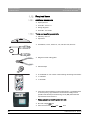
1
MUKOMNN
kÉï=~ë=çÑW==
ebiflabkqmirp
pÉêîáÅÉ=j~åì~ä
båÖäáëÜ
Cover page
US
PL
NT
LI
E
OD
HE
008
. S
7mA DC
70kV 60kV
Sirona Dental Systems GmbH
Service Manual HELIODENTPLUS
1
General information..................................................................................................
6
1.1
Structure of the documents ...........................................................................
6
1.2
General safety information ............................................................................
7
1.3
Operation notes.............................................................................................
7
1.4
Changing the device configuration................................................................
9
1.4.1 Changing the cone length ..................................................................
9
1.4.2 Using and changing a diaphragm ......................................................
9
Replacing parts .............................................................................................
9
1.5.1 Safety-related tests ............................................................................
10
1.6
Demo mode...................................................................................................
10
1.7
List of software versions................................................................................
10
1.8
The most important subassemblies ..............................................................
11
1.9
Labeling.........................................................................................................
12
1.10
Removing covers ..........................................................................................
13
1.10.1 Wall module .......................................................................................
13
1.10.2 Remote control and remote timer.......................................................
15
1.10.3 X-ray tube unit....................................................................................
15
Overview of PC boards .................................................................................
16
1.11.1 Generator board DX1.........................................................................
16
1.11.2 Control board DX4 .............................................................................
17
Required items ..............................................................................................
18
1.12.1 Additional documents.........................................................................
18
1.12.2 Tools and auxiliary materials..............................................................
18
List of messages ......................................................................................................
19
2.1
Error messages .............................................................................................
19
2.1.1 General ..............................................................................................
19
2.1.2 Structure.............................................................................................
19
2.1.3 List of error messages........................................................................
20
1.5
1.11
1.12
2
62 15 102 D3507
D3507.076.01.07.02
08.2011
3
båÖäáëÜ
Table of contents
Sirona Dental Systems GmbH
Service Manual HELIODENTPLUS
3
4
Troubleshooting.......................................................................................................
23
3.1
Error message: NONE .................................................................................
23
3.2
Error message: E1 04 51 - Door contact error .............................................
26
3.3
Error message: E5 01 02 / E5 01 14 / E5 01 12..........................................
27
3.4
Error message: E5 01 22 .............................................................................
28
3.5
Error message: E6 01 23 .............................................................................
29
3.6
Error message: E7 01 01 .............................................................................
31
Maintenance ............................................................................................................
33
4.1
Checking the shielding .................................................................................
33
4.1.1 Test ...................................................................................................
33
4.1.2 Positions............................................................................................
33
Checking the protective ground connections ...............................................
35
4.2.1 Test ...................................................................................................
35
4.2.2 Positions............................................................................................
35
4.3
Checking exposure time and high voltage kV ..............................................
37
4.4
Checking the deadman function...................................................................
38
4.5
Checking the release button.........................................................................
39
4.5.1 General .............................................................................................
39
4.5.2 Release button on PC board DX1 (coiled cable) ..............................
39
4.5.3 Release button on PC board DX4 (coiled cable) ..............................
40
4.5.4 Release button on front panel on PC board DX4 ..............................
41
4.6
Front panel test ............................................................................................
41
4.7
Checking and adjusting the support arm......................................................
43
4.8
Checking the X-ray tube assembly joint .......................................................
44
4.9
Checking the ceiling model ..........................................................................
47
4.10
Checking the tube current ............................................................................
48
4.11
Protective conductor test..............................................................................
49
4.12
Leakage current test.....................................................................................
51
4.2
4
62 15 102 D3507
D3507.076.01.07.02 08.2011
Sirona Dental Systems GmbH
5
6
Service routines.......................................................................................................
53
5.1
Operation......................................................................................................
53
5.2
Overview ......................................................................................................
54
5.3
Service routines (list)....................................................................................
55
5.3.1 Service routine S01...........................................................................
55
5.3.2 Service routine S02...........................................................................
55
5.3.3 Service routine S03...........................................................................
55
5.3.4 Service routine S04...........................................................................
55
5.3.5 Service routine S05...........................................................................
56
5.3.6 Service routine S06...........................................................................
56
5.3.7 Service routine S07...........................................................................
57
5.3.8 Service routine S08...........................................................................
57
5.3.9 Service routine S09...........................................................................
57
5.3.10 Service routine S10...........................................................................
58
5.3.11 Service routine S11...........................................................................
58
5.3.12 Service routine S12...........................................................................
58
5.3.13 Service routine S13...........................................................................
59
5.3.14 Service routine S14...........................................................................
59
5.3.15 Service routine S15...........................................................................
60
5.3.16 Service routine S16...........................................................................
61
5.3.17 Service routine S17...........................................................................
61
5.3.18 Service routine S18...........................................................................
62
5.3.19 Service routine S19...........................................................................
62
5.3.20 Service routine S20...........................................................................
63
5.3.21 Service routine S21...........................................................................
63
5.3.22 Service routine S22...........................................................................
63
5.3.23 Service routine S23...........................................................................
64
5.3.24 Service routine S24...........................................................................
64
5.3.25 Service routine S25...........................................................................
64
5.3.26 Service routine S26...........................................................................
65
5.3.27 Service routine S27...........................................................................
65
Repair ......................................................................................................................
66
6.1
Safety-related tests ......................................................................................
66
6.2
Replacing X-ray tube assembly H1 ..............................................................
66
6.3
Replacing PC board DX1 .............................................................................
72
6.4
Replacing PC board DX4 .............................................................................
73
62 15 102 D3507
D3507.076.01.07.02
08.2011
5
båÖäáëÜ
Service Manual HELIODENTPLUS
1 General information
Sirona Dental Systems GmbH
Service Manual HELIODENTPLUS
1.1 Structure of the documents
1
General information
General information
1.1 Structure of the documents
Structure of the documents
Structure of the documents
The symbols and character formats used in the present manual have the
following meaning:
WARNING
Identifies warnings where a medium risk of injury to persons exists if
they are not observed.
CAUTION
Identifies safety information where the following hazards exist if they are
not observed: Slight risk of injury to persons, risk of property damage or
damage to the product.
NOTICE
Assistance
Identifies additional information, hints and tips.
✔ Prerequisite
Requests you to do something.
➢ Action
or
➢ 1., 2., …
Result
See chapter "Structure of the Identifies a reference to another text
documents [ → 6]“
passage.
● List
“Text between
quotation marks“
6
Identifies a list.
Identifies commands, menu items or
quotations.
62 15 102 D3507
D3507.076.01.07.02 08.2011
Sirona Dental Systems GmbH
1 General information
Service Manual HELIODENTPLUS
1.2 General safety information
1.2 General safety information
General safety information
WARNING
Radiation protection
The valid radiation protection regulations and measures must be
observed. The statutory radiation protection equipment must be used.
In case of malfunctions, cancel the exposure immediately by letting go
of the exposure release button.
Handling boards
CAUTION
Electrical components of the unit can be destroyed.
➢ Please comply with the usual precautionary measures for handling
printed circuit boards (ESD).
➢ Make sure you touch a ground point to discharge yourself prior to
touching the components.
➢ Use an ESD wrist band and connect it to the protective ground wire.
1.3 Operation notes
Operation notes
Nominal line voltage
Nominal voltage:
120V, 200V– 240V
Permissible deviation:
± 10%
Rated current:
At 120 V: 10 A
At 200 – 240 V: 6 – 5 A
Nominal frequency:
50/60 Hz
Internal line impedance:
At 120 V 0.3 ohms
At 200 – 240 V 0.8 ohms
Remote control
The unit may be equipped with a remote control to be used inside the
treatment room or outside of the X-ray room.
The release button with coiled cable can/must be removed from the
remote control and connected directly to the unit for testing.
Keep in mind that the disconnected cable may be the cause of defects.
Switch-on procedure
NOTICE
Do not press any buttons when switching on the unit!
➢ Switch the unit on.
ª It will execute an electronic self-testing routine.
ª The operational readiness indicator must be lit up.
62 15 102 D3507
D3507.076.01.07.02
08.2011
7
båÖäáëÜ
Prior to opening the unit
1 General information
Sirona Dental Systems GmbH
Service Manual HELIODENTPLUS
1.3 Operation notes
Cooling period
The cooling period between two exposures is maintained by an automatic
exposure blocking function according to the pulse/pause ratio.
Software version
The DX4 board determines the software version.
You can find the software version with the following steps:
● Start service routine "2".
● A label next to the main switch includes an imprint of the software
version.
Disturbance of electronic equipment
caused by cell phones
To ensure safe operation of medical electrical equipment, the use of
mobile wireless phones in practice or hospital environments is prohibited.
Disposal
General
Your product is marked with the adjacent symbol. Within the European
Economic Area, this product is subject to Directive 2002/96/EC as well as
the corresponding national laws. This directive requires environmentally
sound recycling/disposal of the product. The product must not be
disposed of as domestic refuse!
Environmentally sound disposal
Please observe the disposal regulations applicable in your country.
X-ray tube unit
The X-ray tube assembly contains a tube which can implode, lead lining,
and mineral oil.
Removing covers
Observe the section on "Removing covers".
Measurements
Observe the following when taking measurements:
● Always switch the unit off before connecting a measuring instrument.
● Select the correct current/voltage type and adjust the measuring
range to match the expected readings.
● Perform continuity tests only on units which are switched off.
● If several exposures with radiation must be taken to check a
measurement, make sure that the prescribed cool-down intervals are
observed.
- They are maintained by an automatic exposure blocking function
(see operating instructions).
● Observe the radiation protection guidelines before releasing the
radiation.
8
62 15 102 D3507
D3507.076.01.07.02 08.2011
Sirona Dental Systems GmbH
1 General information
Service Manual HELIODENTPLUS
1.4 Changing the device configuration
1.4 Changing the device configuration
1.4.1
Changing the device configuration
Changing the cone length
Changing the cone length
Explanation
If the cone length is changed, this change must be registered with service
routine S06 [ → 56].
1.4.2
Using and changing a diaphragm
Using and changing a diaphragm
Explanation
If a diaphragm needs to be used, this change must be registered with
service routine S07 [ → 57].
If a diaphragm is replaced or removed, this change must also be
registered with service routine S07 [ → 57].
båÖäáëÜ
1.5 Replacing parts
Replacing parts
Spare parts
The article numbers for ordering spare parts can be found in the spare
parts list, Order No. 62 34 111
NOTICE
The diagrams contained in the spare parts list provide a useful guide
when replacing parts.
Preparation
➢ Always switch the unit off before replacing parts.
Replacement
The following must be observed when replacing individual
subassemblies:
● The unit must be disconnected from the power supply before
replacing any parts near the power supply, the power switch, or the
power supply board.
● Disconnect the unit from the junction box of the building installation.
● Always wear an ESD wrist band to protect sensitive components on
printed circuit boards (ESD) and attach it to a ground conductor
(green/yellow).
● Always check the unit after replacing PC boards DX1 and DX4 or the
X-ray tube assembly.
● For safety reasons, the support arm must be secured with the safety
belt when replacing the X-ray tube assembly.
62 15 102 D3507
D3507.076.01.07.02
08.2011
9
1 General information
Sirona Dental Systems GmbH
Service Manual HELIODENTPLUS
1.6 Demo mode
1.5.1
Safety-related tests
Safety-related tests
A protective conductor test and a leakage current test must be performed
prior to the installation or the hand-over of the unit as well as after repair
work.
See Sections "Protective conductor test [ → 49]" and "Leakage current
test [ → 51]."
1.6 Demo mode
Demo mode
Activation
1. Set service routine "26" to "On".
2. Switch the unit off.
3. Open the protective cover of the wall module.
4. Attach cables V (blue) and W (pink) on terminal strip X500.
5. Close the protective cover of the wall module.
6. Switch the unit back on.
ª The message "E1 11 88" appears on the display.
7. Acknowledge this message by pressing any key (not a release
button).
ª The demo mode is now activated.
ª When a release button is activated, no X-ray radiation will be
generated.
Deactivation
✔ The unit is in "demo mode".
1. Set service routine "26" to "Off".
2. Switch the unit off.
3. Open the protective cover of the wall module.
4. Attach cable V (blue) to terminal strip X500.1.
5. Attach cable W (pink) on terminal strip X500.2.
6. Close the protective cover of the wall module.
7. Switch the unit back on.
ª The demo mode was deactivated.
ª When a release button is activated, X-ray radiation will be generated.
1.7 List of software versions
List of software versions
10
Software
Remarks
V02.04.00
1. Series release
62 15 102 D3507
D3507.076.01.07.02 08.2011
Sirona Dental Systems GmbH
1 General information
Service Manual HELIODENTPLUS
1.8 The most important subassemblies
1.8 The most important subassemblies
The most important subassemblies
Position
Designation
A
X-ray tube unit
B
Scissor arm
C
Support arm
D
Wall module
● Board DX1
● Front panel
● Control board DX4
E
Remote Timer (Optional)
● Front panel
Remote control (optional)
Position
Designation
A
X-ray tube assembly on ceiling mount
B
LEDview on ceiling support
båÖäáëÜ
● Control board DX4
F
A
B
62 15 102 D3507
D3507.076.01.07.02
08.2011
11
1 General information
Sirona Dental Systems GmbH
Service Manual HELIODENTPLUS
1.9 Labeling
1.9 Labeling
Labeling
Item
Designation
Info
10
ID label of X-ray tube assembly
attached inside the cone
11
ID label of wall adapter
12
ID label of scissor arm
14
"Follow the operating instructions" label
15
ID label of round cone extension
transp. / white print
16
ID label of square cone extension
transp. / white print
12
62 15 102 D3507
D3507.076.01.07.02 08.2011
Sirona Dental Systems GmbH
1 General information
Service Manual HELIODENTPLUS
1.10 Removing covers
Item
Designation
Info
17
ID label of radiation field limiter 2x3
18
ID label of radiation field limiter 3x4
20
Warning label for HELIODENT PLUS
yellow / black print
21
Warning label for X-ray unit
Affixed on site
32
ID label of LEDview
40
DHHS label about Regulations 21CFR (45x27)
transp. / white print
42
DHHS label UL-CSA
white / black print
50
Chinese label for HELIODENT PLUS
51
Chinese label for HELIODENT PLUS (ID)
53
Chinese label for CCIB
båÖäáëÜ
1.10 Removing covers
Removing covers
1.10.1
Wall module
Wall module
Removing the cover
1. Switch the unit off.
C
2. Unlock the housing shell (C) of the support arm above the wall
module by pinching the housing shells together at position (S).
S
3. Remove the housing shell (C) from the support arm.
4. Unscrew and remove the fastening screws (A) from the underside.
B
A
62 15 102 D3507
D3507.076.01.07.02
08.2011
13
1 General information
Sirona Dental Systems GmbH
Service Manual HELIODENTPLUS
1.10 Removing covers
5. Pull the protective cover (B) slightly away from the wall and lift it up.
ª You can now remove the protective cover.
B
Hanging up the cover
➢ Hang the cover on the side of the wall adapter plate so that it is
securely positioned (see illustration).
14
62 15 102 D3507
D3507.076.01.07.02 08.2011
Sirona Dental Systems GmbH
1 General information
Service Manual HELIODENTPLUS
1.10 Removing covers
1.10.2
Remote control and remote timer
➢ Detach the housing of the remote control or the Remote Timer by
carefully inserting the tip of a screwdriver in opening A and pressing
against the catch. Do not pry with or turn the screwdriver!
1.10.3
båÖäáëÜ
Remote control and remote timer
X-ray tube unit
1. Unscrew and remove the cover (A).
X-ray tube unit
A
2. Remove the arm cover (L).
L
62 15 102 D3507
D3507.076.01.07.02
08.2011
15
1 General information
Sirona Dental Systems GmbH
Service Manual HELIODENTPLUS
1.11 Overview of PC boards
1.11 Overview of PC boards
Overview of PC boards
1.11.1
Generator board DX1
Generator board DX1
S1
Power switch
F200/
F201
Fuse for PFC
(10A 250V slow-blow, order no.: 10 77 460)
F300
Fuse for switched-mode power supply
(1A 250V quick-blow, order no.: 10 77 304)
V316
LED, supply voltage +15V
- LED lights up when +15 V supply voltage is
present.
X400
Direct contact with control board DX4 [ → 17] /
cable L2 or L6.
X401
Release and safety circuit only for installation
options 1, 2, 4, 6 and 6.1
V409
LED, setpoint generation
- LED lights up during an X-ray exposure.
V413
LED, basic heating
- LED lights up when basic heating is correct.
- LED lights up during an X-ray exposure.
V414
LED, kV controller
- LED lights up during an X-ray exposure if the
kV controller is functioning correctly.
V503
LED, kVactual cable
- LED lights up if the kVactual cable is
incorrectly connected.
16
62 15 102 D3507
D3507.076.01.07.02 08.2011
Sirona Dental Systems GmbH
1 General information
Service Manual HELIODENTPLUS
1.11 Overview of PC boards
D500
Glow lamp, output stage
- The glow lamp lights up during an X-ray
exposure. The high-voltage transformer is
activated.
V611
LED, release
- LED lights up when the release button is
pressed.
1.11.2
X600
Measuring points for the tube current
measurement (see section "Checking the tube
current [ → 48]“).
Control board DX4
båÖäáëÜ
Control board DX4
(A)
Protective circuit (door contact)
(B)
Release button
(C)
EMC shielding
V108
LED, +3.3 V for LCD
V200
LED, Debugging
V201
LED, status indicator
- LED flashes with 100% unit function.
H200
Acoustic signal
- Acoustic signal sounds during an X-ray
exposure.
V503
LED, +8V input voltage
X103
Direct contact with generator board DX1 [ → 16]
/ cable L2
(installation options 1, 2, 4, 6 and 6.1)
X105, Direct contact with generator board DX1 [ → 16]
X106 as remote control / cable L6
(installation options 3, 5, 7 and 8)
V600
LED, +5.0 V supply voltage
V602
62 15 102 D3507
D3507.076.01.07.02
08.2011
LED, +3.3 V controller voltage
17
1 General information
Sirona Dental Systems GmbH
Service Manual HELIODENTPLUS
1.12 Required items
1.12 Required items
1.12.1
Required items
Additional documents
Additional documents
● Spare parts list
● Order No.: 62 34 111
● Wiring diagrams
● Order No.: 62 15 086
1.12.2
Tools and auxiliary materials
Allen
size 13: materials
Tools key
and/ auxiliary
● Allen key / size 13:
● Spirit level
Spirit level (general purpose)
● Screwdriver, Torx®, sizes T10, T15, T20 and T30, 200 mm
Diagonal-nosed cutting pliers
● Diagonal-nosed cutting pliers
General purpose adhesive tape
● adhesive tape
● 2x multimeter or one of each of the following measuring instruments:
● 1x voltmeter
● 1x ammeter
Bender tester
● Test unit for device leakage current measurement, e.g. Bender tester
or line-frequency, high-resistance measurement voltage source
(isolation transformer) and measuring circuit (MD) that meets the
requirements of IEC 60 601-1.
Power source
● Power source for protective ground wire test
Technical data:
● No-load voltage max. 6V
● Short-circuit current at least 5A - max. 25A
18
62 15 102 D3507
D3507.076.01.07.02 08.2011
Sirona Dental Systems GmbH
2 List of messages
Service Manual HELIODENTPLUS
2.1 Error messages
2
List of messages
List of messages
2.1 Error messages
2.1.1
Error messages
General
General
Explanation
The error messages appear on the display of the control electronics.
Recognition
Error messages can be recognized by a six-digit error code (Ex yy zz)
beginning with a large E.
Handling error messages
As a general rule, error messages are acknowledged via all buttons
except for the release button.
If trouble-free operation is possible after the error is acknowledged, then
no further action is necessary.
If error messages reoccur or occur frequently or trouble-free operation is
not possible, identify the error as described in the section "List of error
messages [ → 20]" and take appropriate action to eliminate the
corresponding error or fault.
2.1.2
Structure
Structure
Explanation
The codes provide you with error type, error location and troubleshooting
information. Plain text error output follows.
Configuration
The error codes are structured according to the following pattern: Ex yy zz
Explanation of abbreviations:
Ex – Error type
"Remedy" classification for the user. The x character provides a
foundation for making quick decisions as to how serious the error is and
how to handle the error.
yy – Locality
Describes the impacted functionality.
This functionality can be:
● Subassembly
● Subsystem
● Logical functional unit
zz – Identification
Describes a further specification of the error via a consecutive number
with error identification.
62 15 102 D3507
D3507.076.01.07.02
08.2011
19
båÖäáëÜ
The structure of the error messages is explained in the section entitled
"Structure [ → 19]".
2 List of messages
Sirona Dental Systems GmbH
Service Manual HELIODENTPLUS
2.1 Error messages
2.1.3
List of error messages
List of error messages
Error code
Description
Actions required
None
Release does not result in any reaction/
exposure
See Section
""Error message NONE [ → 23]"
E1 11 88
Demo mode ACTIVE
Acknowledge the error message with any
key.
For "normal operation" - change service
routine 26 [ → 65]
E1 04 03
Acknowledge the error message with any
key.
If the error message reappears, DX4 must
be replaced.
E1 04 04
Error programming the values.
Acknowledge the error message with any
key.
If the error message reappears, DX4 must
be replaced.
E1 04 51
Safety circuit (door contact)
See Section
""Error message E1 04 51 [ → 26]"
E1 04 60
Error of serial port
Replace DX4.
E3 04 30
Power-up error
Switch unit OFF and ON again
Release button was actuated during power-on
If the error message reappears, remove
the release button.
If there are no more error messages, use a
new release button.
If the error message persists, check the
cable between DX1 and DX4. DX4 may
need to be replaced
E3 04 31
Error keys
Switch unit OFF and ON again
A front panel key was actuated during power-on If the error reoccurs, perform a key test with
service routine 20 [ → 63]
Key defective? Replace front panel
E5 01 02
No target values are generated
E5 01 12
DX4 buzzer sounds, no exposure
E5 01 14
E5 01 32
Check the cable between DX1 and DX4
(B4). Replace the entire cable if necessary.
If the error message reappears, DX1 must
be replaced.
E5 01 42
E5 01 02
Buzzer sounds
E5 01 12
No exposure
Replace DX1
E5 01 14
E5 01 32
E5 01 02
Buzzer sounds
E5 01 12
No exposure
E5 01 14
20
See Section
""Error message E5 01 02 / E5 01 12 / E5
01 14 [ → 27]"
62 15 102 D3507
D3507.076.01.07.02 08.2011
Sirona Dental Systems GmbH
2 List of messages
Service Manual HELIODENTPLUS
2.1 Error messages
Error code
Description
Actions required
E5 01 02
Buzzer sounds
Replace DX1
E5 01 14
no exposure temporarily
E7 01 51
E5 01 22
Buzzer does not sound
No exposure
E5 04 50
Internal software error
See Section
""Error message E5 01 22 [ → 28]"
Switch unit OFF and ON again
Repeat the exposure with the same values
E6 01 13
Internal hardware error
Replace DX1.
E6 01 31
Internal hardware error
Replace DX1
E6 01 41
Buzzer sounds although the release was not
actuated
Switch unit OFF and ON again
If the error message reappears, DX4 must
be replaced
If the error message reappears, DX1 must
be replaced
E6 01 23
Cable is incorrectly attached or internal
hardware error
See Section
""Error message E6 01 23 [ → 29]"
E6 01 11
Internal hardware error
Replace DX1
E6 01 61
Error diagnosis not working
Check the cable between DX1 and DX4.
Cable may need to be replaced
E6 01 62
Error diagnosis not working
Check the cable between DX1 and DX4.
Cable may need to be replaced
If the error message reappears, DX1 must
be replaced
E6 04 01
Internal hardware error
Switch unit OFF and ON again
If the error message reappears, DX4 must
be replaced
E6 04 02
Internal error
Switch unit OFF and ON again
If the error message reappears, DX4 must
be replaced
E6 04 11
Internal error
Replace DX4
E6 04 40
LCD is somewhat darker in some cases
Replace DX4
E6 04 41
Power supply of DX4 is interrupted
Switch unit OFF and ON again
If the error message reappears, DX4 must
be replaced
E6 04 42
Power supply of DX4 is interrupted
Replace DX4
E6 04 10
Internal error
Switch unit OFF and ON again
If the error message reappears, DX4 must
be replaced
62 15 102 D3507
D3507.076.01.07.02
08.2011
21
båÖäáëÜ
If the error message reappears, DX4 must
be replaced.
2 List of messages
Sirona Dental Systems GmbH
Service Manual HELIODENTPLUS
2.1 Error messages
Error code
Description
Actions required
E6 04 06
Internal error
Switch unit OFF and ON again
If the error message reappears, DX4 must
be replaced
E6 04 12
Internal error
Switch unit OFF and ON again
If the error message reappears, DX4 must
be replaced
E6 04 20
Internal error
Switch unit OFF and ON again
If the error message reappears, DX4 must
be replaced
E6 04 21
Internal error
Switch unit OFF and ON again
If the error message reappears, DX4 must
be replaced
E7 01 01
Cable is incorrectly attached or internal
hardware error
See Section
""Error message E7 01 01 [ → 31]"
E7 01 21
Release actuated
Check the cable between DX1 and DX4.
No buzzer sound
Cable may need to be replaced
No exposure
E7 01 51
Internal hardware error
Switch unit OFF and ON again
If the error message reappears, DX1 must
be replaced
22
62 15 102 D3507
D3507.076.01.07.02 08.2011
Sirona Dental Systems GmbH
3 Troubleshooting
Service Manual HELIODENTPLUS
3.1 Error message: NONE
3
Troubleshooting
Troubleshooting
3.1 Error message: NONE
båÖäáëÜ
Error message: NONE
62 15 102 D3507
D3507.076.01.07.02
08.2011
23
3 Troubleshooting
3.1 Error message: NONE
24
Sirona Dental Systems GmbH
Service Manual HELIODENTPLUS
62 15 102 D3507
D3507.076.01.07.02 08.2011
Sirona Dental Systems GmbH
3 Troubleshooting
3.1 Error message: NONE
båÖäáëÜ
Service Manual HELIODENTPLUS
62 15 102 D3507
D3507.076.01.07.02
08.2011
25
3 Troubleshooting
Sirona Dental Systems GmbH
Service Manual HELIODENTPLUS
3.2 Error message: E1 04 51 - Door contact error
3.2 Error message: E1 04 51 - Door contact error
Error message: E1 04 51 - Door contact error
Explanation
Depending on the installation type, there are different approaches to
address error message E1 04 51.
● Error correction (case 1)
● Installation type "Wall box without door contact"
● Installation type "Remote without door contact"
● Error correction (case 2)
● Installation type "Wall box with door contact"
Error correction (case 1)
1. Set switch S2 on PC board DX4 to ON.
2. In service routine 012, set the value "1" and save it.
3. Switch the unit off and then on again.
Error correction (case 2)
1. Set switch S2 on PC board DX4 to OFF.
2. In service routine 012, set the value "0" and save it.
3. Switch the unit off and then on again.
26
62 15 102 D3507
D3507.076.01.07.02 08.2011
Sirona Dental Systems GmbH
3 Troubleshooting
Service Manual HELIODENTPLUS
3.3 Error message: E5 01 02 / E5 01 14 / E5 01 12
3.3 Error message: E5 01 02 / E5 01 14 / E5 01 12
båÖäáëÜ
Error message: E5 01 02 / E5 01 14 / E5 01 12
62 15 102 D3507
D3507.076.01.07.02
08.2011
27
3 Troubleshooting
Sirona Dental Systems GmbH
Service Manual HELIODENTPLUS
3.4 Error message: E5 01 22
3.4 Error message: E5 01 22
Error message: E5 01 22
28
62 15 102 D3507
D3507.076.01.07.02 08.2011
Sirona Dental Systems GmbH
3 Troubleshooting
Service Manual HELIODENTPLUS
3.5 Error message: E6 01 23
3.5 Error message: E6 01 23
båÖäáëÜ
Error message: E6 01 23
62 15 102 D3507
D3507.076.01.07.02
08.2011
29
3 Troubleshooting
3.5 Error message: E6 01 23
30
Sirona Dental Systems GmbH
Service Manual HELIODENTPLUS
62 15 102 D3507
D3507.076.01.07.02 08.2011
Sirona Dental Systems GmbH
3 Troubleshooting
Service Manual HELIODENTPLUS
3.6 Error message: E7 01 01
3.6 Error message: E7 01 01
båÖäáëÜ
Error message: E7 01 01
62 15 102 D3507
D3507.076.01.07.02
08.2011
31
3 Troubleshooting
3.6 Error message: E7 01 01
32
Sirona Dental Systems GmbH
Service Manual HELIODENTPLUS
62 15 102 D3507
D3507.076.01.07.02 08.2011
Sirona Dental Systems GmbH
4 Maintenance
Service Manual HELIODENTPLUS
4.1 Checking the shielding
4
Maintenance
Maintenance
4.1 Checking the shielding
4.1.1
Checking the shielding
Test
Test
➢ Check whether the cable shieldings have contact with the shielding
clamps and are firmly in place.
4.1.2
Positions
Positions
Installation panel (wall module)
● If available: Manual release S3 on X401
båÖäáëÜ
● (B): Clamp
● If available: Cable L2 with ferrite core on X400
● (C): Clamp
● If available: Cable L6 on X400
● (D): Clamp
62 15 102 D3507
D3507.076.01.07.02
08.2011
33
4 Maintenance
Sirona Dental Systems GmbH
Service Manual HELIODENTPLUS
4.1 Checking the shielding
DX4 (wall module)
● X103 / L2 cable (wall mounting)
● (E): Clamp
DX4 (Remote Timer)
● Grounding tab of the front panel
● (F): Screw
● X106/X105 / L6 cable
● (G): Clamp
● X109 / Manual release S3
● (H): Clamp
● (I): Release button
34
62 15 102 D3507
D3507.076.01.07.02 08.2011
Sirona Dental Systems GmbH
4 Maintenance
Service Manual HELIODENTPLUS
4.2 Checking the protective ground connections
4.2 Checking the protective ground connections
Checking the protective ground connections
4.2.1
Test
Test
➢ Check whether all protective ground connections are firmly in place.
4.2.2
Positions
Positions
DX1 and installation panel (wall module)
båÖäáëÜ
● X200 / Power input clamp
● X500 / Output stage and installation panel
● (A): Screw
X-ray tube unit
● Grounding of the support bracket
● (J): Screw
62 15 102 D3507
D3507.076.01.07.02
08.2011
35
4 Maintenance
Sirona Dental Systems GmbH
Service Manual HELIODENTPLUS
4.2 Checking the protective ground connections
● Grounding of the X-ray tube assembly
● (K): Screw
36
62 15 102 D3507
D3507.076.01.07.02 08.2011
Sirona Dental Systems GmbH
4 Maintenance
Service Manual HELIODENTPLUS
4.3 Checking exposure time and high voltage kV
4.3 Checking exposure time and high voltage kV
Checking exposure time and high voltage kV
Auxiliary devices required
● Suitable radiation meter.
● Examples:
● Mini-X
● PMX I-D
● MOM
båÖäáëÜ
Preparation
1. Switch the X-ray unit on.
2. Wait until the self-test is finished (operational readiness signal must
be lit). The display reading shows the radiation time and a patient
symbol).
3. Set an exposure time between 0.25 and 0.4 seconds. The display of
control board DX4 must be clearly visible
4. Position the measuring instrument (B) in such a way that the active
sensor measuring surface has a distance of 50 cm (19.7") from the
focus (A) of the X-ray tube assembly.
5. Switch on the measuring instrument.
62 15 102 D3507
D3507.076.01.07.02
08.2011
37
4 Maintenance
Sirona Dental Systems GmbH
Service Manual HELIODENTPLUS
4.4 Checking the deadman function
test
WARNING
X-ray radiation!
➢ Release an exposure with the release button.
● The buzzer must be audible during radiation release.
● The radiation indicator lights up.
● The radiation LED lights up yellow.
● The display background lights up yellow.
➢ Check the measures exposure time and the high voltage measured
at the measuring instrument.
Tolerance: The permitted tolerance of the exposure time and high voltage
is ±10%.
In case of error
● Radiation time outside of tolerance limits
● Replace board DX4.
● High voltage outside of tolerance limits
● Replace DX1.
4.4 Checking the deadman function
Checking the deadman function
test
1. Set the radiation time to 3.2 seconds (display: "3.20 s").
WARNING
X-ray radiation!
2. Release an exposure with the release button and let go of the release
button prior to the end of the radiation.
ª The radiation must stop.
ª The actual radiation time must be shown as a flashing display.
In case of an error
The unit does not stop releasing radiation.
➢ Replace board DX4.
38
62 15 102 D3507
D3507.076.01.07.02 08.2011
Sirona Dental Systems GmbH
4 Maintenance
Service Manual HELIODENTPLUS
4.5 Checking the release button
4.5 Checking the release button
Checking the release button
4.5.1
General
General
Explanation
Depending on the installation type, there are different descriptions for
checking the release button.
Overview
● Release button on PC board DX1 (coiled cable) [ → 39]
● Release button on PC board DX4 (coiled cable) [ → 40]
● Release button on front panel on PC board DX4 [ → 41]
Release button on PC board DX1 (coiled cable)
båÖäáëÜ
4.5.2
Release button on PC board DX1 (coiled cable)
NOTICE
Only one release button may be connected (active)!
Preparation
1. Switch the unit off.
2. Connect the measuring instrument:
● With installed door contact
- Connect the measuring instrument to DX1 X401.1 and X401.2.
● With no installed door contact
- Connect the measuring instrument to DX1 X401.1 and X401.4.
test
➢ Check the following points:
● Is the strain relief of the coiled cable fully functional?
● Is the release button easy to actuate?
● Does the release button return to its home position on its own after
letting go?
● With release button not pressed: Measured resistance exceeds
100k Ω .
● With release button pressed: Measured resistance is below 100 Ω .
● Do the measured resistance values remain constant when the coiled
cable is moved?
➢ After the test: Remove the measuring instrument.
In case of an error
➢ Replace the release button with coiled cable.
62 15 102 D3507
D3507.076.01.07.02
08.2011
39
4 Maintenance
Sirona Dental Systems GmbH
Service Manual HELIODENTPLUS
4.5 Checking the release button
4.5.3
Release button on PC board DX4 (coiled cable)
Release button on PC board DX4 (coiled cable)
NOTICE
Only one release button may be connected (active)!
Preparation
1. Switch the unit off.
2. Connect the measuring instrument:
● With installed door contact
- Connect the measuring instrument to DX4 X100.1 and X100.2.
● With no installed door contact
- Connect the measuring instrument to DX4 X100.1 and X100.4.
test
➢ Check the following points:
● Is the strain relief of the coiled cable fully functional?
● Is the release button easy to actuate?
● Does the release button return to its home position on its own after
letting go?
● With release button not pressed: Measured resistance exceeds
100k Ω .
● With release button pressed: Measured resistance is below 100 Ω .
● Do the measured resistance values remain constant when the coiled
cable is moved?
➢ After the test: Remove the measuring instrument.
In case of an error
➢ Replace the release button with coiled cable.
40
62 15 102 D3507
D3507.076.01.07.02 08.2011
Sirona Dental Systems GmbH
4 Maintenance
Service Manual HELIODENTPLUS
4.6 Front panel test
4.5.4
Release button on front panel on PC board DX4
Release button on front panel on PC board DX4
NOTICE
Only one release button may be connected (active)!
Preparation
1. Switch the unit off.
2. Connect the measuring instrument to DX1 X401.1 and X401.3.
test
➢ Check the following points:
● Does the release button return to its home position on its own after
letting go?
● With release button not pressed: Measured resistance exceeds 1k Ω .
● With release button pressed: Measured resistance is below 100 Ω .
➢ After the test: Remove the measuring instrument.
In case of an error
➢ Replace the front panel.
4.6 Front panel test
Front panel test
Explanation
In the front panel test, you can check the function of every individual key
on the front panel.
Command
➢ Open service routine S22 (see "Operation [ → 53]" in the Section
"Service routines").
Operation
➢ Actuate every key in sequence.
ª A code is indicated in a certain area on the display each time a key is
actuated.
Areas
A
S22
62 15 102 D3507
D3507.076.01.07.02
08.2011
B
C
D
41
båÖäáëÜ
● Is the release button easy to actuate?
4 Maintenance
Sirona Dental Systems GmbH
Service Manual HELIODENTPLUS
4.6 Front panel test
Code table
Key
+
_
Area
Code
A
Key
Area
Code
1
B
32
A
2
B
64
A
4
B
128
A
8
C
1
B
2
C
2
B
4
C
4
C
8
D
1
60kV
B
8
70kV
B
42
16
62 15 102 D3507
D3507.076.01.07.02 08.2011
Sirona Dental Systems GmbH
4 Maintenance
Service Manual HELIODENTPLUS
4.7 Checking and adjusting the support arm
4.7 Checking and adjusting the support arm
Checking and adjusting the support arm
CAUTION
Switch OFF the unit before connecting a measuring instrument or
replacing parts!
Check
● Are all bellows intact?
- If the bellows are damaged, the support arm must be replaced. See
Section "Replacing the support arm."
● Does the X-ray tube assembly drift from its work position on its own?
- If the X-ray tube assembly drifts, the support arm must be readjusted.
båÖäáëÜ
Setting
Adjusting the spring on the scissor arm (support arm side)
1. Invert the bellows over the half-shells (A) on both sides.
2. Pull off the half-shells.
3. Pull the scissor arm apart and slide the bellows over the bearing.
4. Set both support arms in vertical position.
5. Insert the Torx screwdriver (T30, 200 mm) into the drilling of the
bearing from the top and adjust the spring (right turn = tighter).
6. Reassemble the support arm by completing the same steps in
reverse order.
Adjusting the spring on the scissor arm (X-ray tube assembly side)
1. Invert the bellows over the upper half-shell (A).
2. Press the bellows downward.
3. Set the support arm into a horizontal position.
4. Insert the Torx screwdriver (T30, 200 mm) into the drilling of the
bearing from the front and adjust the spring (right turn = tighter).
5. Reassemble the support arm by completing the same steps in
reverse order.
62 15 102 D3507
D3507.076.01.07.02
08.2011
43
4 Maintenance
Sirona Dental Systems GmbH
Service Manual HELIODENTPLUS
4.8 Checking the X-ray tube assembly joint
4.8 Checking the X-ray tube assembly joint
Checking the X-ray tube assembly joint
CAUTION
Switch OFF the unit before connecting a measuring instrument or
replacing parts!
Required tools
Torx screwdriver (size 10, 15 and 20)
Check
● Does the cone remain set in every position?
● Are the connecting cables intact?
● See section on "Checking the connection cables".
If the X-ray tube assembly fails any of these check points, it must be
replaced (see Section "Replacing X-ray tube assembly H1 [ → 66]").
Checking the connection cables
1. Switch the X-ray unit off.
2. Unscrew and remove the old cover (A).
A
3. Remove the arm cover (L).
L
44
62 15 102 D3507
D3507.076.01.07.02 08.2011
Sirona Dental Systems GmbH
Service Manual HELIODENTPLUS
4 Maintenance
4.8 Checking the X-ray tube assembly joint
4. Check the condition of the grounding strap.
ª No damage should be evident at position (K). Slight restriction at
the position (K) of up to 20% cross-section loss is acceptable.
K
5. Check the screw terminal on the grounding wire (B) for damage.
båÖäáëÜ
B
6. Check the plug contacts on the connector (X1) for damage.
62 15 102 D3507
D3507.076.01.07.02
08.2011
45
4 Maintenance
Sirona Dental Systems GmbH
Service Manual HELIODENTPLUS
4.8 Checking the X-ray tube assembly joint
7. Check the scissor arm (J) to make sure it does not brush against a
cable when moved.
J
ª No cable should touch the scissor arm in any position. Fasten the
cable with a cable tie if necessary.
8. Attach the arm cover (L).
L
9. Attach and secure the cover (A).
A
46
62 15 102 D3507
D3507.076.01.07.02 08.2011
Sirona Dental Systems GmbH
4 Maintenance
Service Manual HELIODENTPLUS
4.9 Checking the ceiling model
4.9 Checking the ceiling model
Checking the ceiling model
Ceiling model checks
● Is the ceiling fastening (A) secure?
● Are the cover parts (B) present and free of damage?
X1
SXL
X4
X2
båÖäáëÜ
6 7 8 9
A
B
● Is the ground wire connection (C) secured?
L8
8 N
L 7 6 5
D
4 3 2 1
X1
X4
SXL
Kl 10
● Are the cables free from damage, and do they fit securely as
prescribed to terminal K10 (D) in the ceiling model?
X2
N
L 7 6 5
4 3 2 1
6 7 8 9
8 N
L
L7
KL 10
C
Wall adapter checks
● Is the ground wire connection (F) secured?
● Are the cables free from damage, and do they fit securely as
prescribed to terminal X100 (E) in the wall adapter?
62 15 102 D3507
D3507.076.01.07.02
08.2011
47
4 Maintenance
Sirona Dental Systems GmbH
Service Manual HELIODENTPLUS
4.10 Checking the tube current
4.10 Checking the tube current
Checking the tube current
Auxiliary devices required
● Ammeter
CAUTION
Only use battery-powered measuring devices.
Preparation
1. Switch the unit off.
2. Set the ammeter to the "10 mA DC" measuring range.
3. Connect the ammeter to the two outer X600 connectors on board
DX1.
4. Switch the unit on.
5. Set the radiation time to 3.2 seconds (display: "3.20 s").
test
WARNING
X-ray radiation!
➢ Release an exposure with the release button and read the tube
current from the ammeter.
Tolerance: The tube current must be 7 mA ±1.4mA.
48
62 15 102 D3507
D3507.076.01.07.02 08.2011
Sirona Dental Systems GmbH
4 Maintenance
Service Manual HELIODENTPLUS
4.11 Protective conductor test
Completion
1. Switch the unit off.
2. Remove the measuring wires of the ammeter from connector X600.
3. Reattach the housing on the wall module.
In case of an error
● The measurement value is not reached.
● Replace the X-ray tube assembly.
4.11 Protective conductor test
Protective conductor test
Auxiliary devices required
● Power source
båÖäáëÜ
● Technical data:
● No-load voltagemax. 6V.
● Short-circuit currentmin. 5A - max. 25A
● Ammeter
● Observe the current intensity of the power source
● Voltmeter
Preparation
WARNING
Potentially lethal shock hazard
Switch the line voltage off.
1. Switch the line voltage at the main switch of the building installation
off.
2. Remove the power cable from connector X200 on PC board DX1.
Visual check
1. Check the assembly and firm seating of the ground conductor.
2. Check the main fuse (F200, F201).
3. Check the condition of the grounding strap.
ª No damage should be evident at position (K). Slight restriction at
the position (K) of up to 20% cross-section loss is acceptable.
K
62 15 102 D3507
D3507.076.01.07.02
08.2011
49
4 Maintenance
Sirona Dental Systems GmbH
Service Manual HELIODENTPLUS
4.11 Protective conductor test
Protective ground wire test
Explanation
This test checks the electrical resistance of conductive and exposed parts
of the X-ray unit against the protective wire connection.
Test assembly
See drawing.
test
1. Set the test current for at least 5 seconds between protective wire
connection X200 / PE (board DX1) and ground connection B (X-ray
tube assembly).
2. Read the voltage drop at the voltmeter and the current at the
ammeter.
3. Calculate the protective conductor resistance with the
formula "R = U / I."
Limit value
The calculated resistance value is not permitted to exceed 0.2 Ω .
50
62 15 102 D3507
D3507.076.01.07.02 08.2011
Sirona Dental Systems GmbH
4 Maintenance
Service Manual HELIODENTPLUS
4.12 Leakage current test
4.12 Leakage current test
Leakage current test
Auxiliary devices required
● Line-frequency, high-resistance measurement voltage source
(isolation transformer)
● A measuring circuit (MD) that meets the requirements of IEC 60 6011.
● Voltmeter
Alternative
Complete test units, e.g. the "Bender tester", fulfill these requirements as
well.
Equivalent device leakage current measurement
båÖäáëÜ
Test assembly
1. Connect the measurement voltage source to the measuring circuit
(MD).
2. Connect the voltmeter to the measuring circuit (MD).
3. Connect the measuring circuit (MD) to the metallic part (B) of the wall
module housing.
4. Short-circuit the power connection (N and L) with a suitable cable.
62 15 102 D3507
D3507.076.01.07.02
08.2011
51
4 Maintenance
Sirona Dental Systems GmbH
Service Manual HELIODENTPLUS
4.12 Leakage current test
5. Connect the measurement voltage source to the shorted power
connection (A).
6. Switch on the power supply of the unit.
Test
WARNING
Potentially lethal shock hazard!
Do not touch the unit while measuring the leakage current!
1. Switch the measurement voltage source on.
2. Read the voltage drop at the voltmeter and adjust the measuring
range if necessary.
3. Switch the measurement voltage source off.
Calculation
The measured value is the exact equivalent of the leakage current.
Measuring range
Leakage current
mV
µA
V
mA
Limit value of wall model
The measured value must not exceed 0.55mA.
Limit value of ceiling model
The measured value must not exceed 2.0mA.
NOTICE
Always document your measuring results for comparative
measurements performed later.
➢ Enter the measured values in the maintenance certificate.
➢ Describe the measuring instrument used (to ensure reproducibility).
52
62 15 102 D3507
D3507.076.01.07.02 08.2011
Sirona Dental Systems GmbH
5 Service routines
Service Manual HELIODENTPLUS
5.1 Operation
5
Service routines
Service routines
5.1 Operation
Operation
1. Switch the unit on.
+
+
_
ª The service routine "S01" is displayed in front of a white
background.
3. Scroll through the list of service routines by pressing the +/- keys.
4. Press the Film key to show the setting of the displayed service routine
and make any changes which then may be necessary.
ª The setting is displayed.
5. To change the setting, press the +/- keys.
6. To save the current service routine, press the Adult key.
7. To discard the settings of the current service routine and quit it, press
the Child key.
8. Finally, switch the unit off and then on again.
62 15 102 D3507
D3507.076.01.07.02
08.2011
53
båÖäáëÜ
+
2. Press the Film key, the Sensor key and the Bite Wing key
simultaneously.
5 Service routines
Sirona Dental Systems GmbH
Service Manual HELIODENTPLUS
5.2 Overview
5.2 Overview
Overview
54
Service routine
Function
S01
Configuration of transparency compensation for
films [ → 55]
S02
Configuration of transparency compensation for
sensors [ → 55]
S03
Display of software version [ → 55]
S04
Selection of film type [ → 55]
S05
Selection of sensor type [ → 56]
S06
Selection of cone type [ → 56]
S07
Set diaphragm type [ → 57]
S08
Configuration of radiation time and dose display
after an X-ray exposure [ → 57]
S09
Configuration of time-out time of the radiation
time and dose display [ → 57]
S10
Configuration of display options: Area dose and
actual radiation time [ → 58]
S11
Configuration of power-save mode [ → 58]
S12
Configuration of time-out time of the power-save
mode [ → 58]
S13
Configuration of 60/70 kV toggle [ → 59]
S14
Configuration of detector medium toggle (film/
sensor) [ → 59]
S15
Configuration of safety circuit bypass [ → 60]
S16
Configuration of the dynamic pulse/pause ratio
(dynamic cooling) [ → 61]
S17
Dose rate correction [ → 61]
S18
Setting the display contrast [ → 62]
S19
Setting the display brightness and color [ → 62]
S20
Setting the LED brightness [ → 63]
S21
Display self-test [ → 63]
S22
Front panel test [ → 63]
S23
Display of the exposure and radiation time
counter [ → 64]
S24
Reading the status log [ → 64]
S25
Display of saved data [ → 64]
S26
Activation of demo mode [ → 65]
S27
Resetting the unit to factory default
settings [ → 65]
62 15 102 D3507
D3507.076.01.07.02 08.2011
Sirona Dental Systems GmbH
5 Service routines
Service Manual HELIODENTPLUS
5.3 Service routines (list)
5.3 Service routines (list)
Service routines (list)
5.3.1
Service routine S01
Service routine S01
Explanation
Configuration of transparency compensation for films
Configuration
You can adjust the transparency compensation in the range from -6 to +6
by pressing the +/- keys (factory default setting = "0").
5.3.2
Service routine S02
Service routine S02
Configuration of transparency compensation for sensors
Configuration
You can adjust the transparency compensation in the range from -6 to +6
with the +/- keys (factory default setting = "0").
5.3.3
Service routine S03
Service routine S03
Explanation
Display of software version
5.3.4
Service routine S04
Service routine S04
Explanation
Selection of film type
You can toggle between the following film types:
● FILM D
● FILM E
● FILM F
Operation
Toggle between the film types by pressing the +/- keys.
Legend
62 15 102 D3507
D3507.076.01.07.02
08.2011
Display
Film type
FILM D
FILM D
FILM E
FILM E (factory default setting)
FILM F
FILM F
55
båÖäáëÜ
Explanation
5 Service routines
Sirona Dental Systems GmbH
Service Manual HELIODENTPLUS
5.3 Service routines (list)
5.3.5
Service routine S05
Service routine S05
Explanation
Selection of sensor type
You can toggle between the following sensor types:
● Sirona sensor
● Non-Siemens sensor
● Imaging plate
Operation
Toggle between the sensor types by pressing the +/- keys.
Legend
5.3.6
Display
Sirona
Sensor type
General
Non-Siemens sensor
Scanner
Imaging plate
Sirona XIOS/XIOSPlus sensor
(factory default setting)
Service routine S06
Service routine S06
Explanation
Selection of focus type (cone length)
You can toggle between the following focus types (cone lengths):
● 200 mm (8")
● 300 mm (12")
Operation
Toggle between the focus types by pressing the +/- keys.
Legend
56
Display
Cone length in mm
(Focus type)
200mm (8")
200 mm (8") (factory default setting)
300mm (12")
300 mm (12")
62 15 102 D3507
D3507.076.01.07.02 08.2011
Sirona Dental Systems GmbH
5 Service routines
Service Manual HELIODENTPLUS
5.3 Service routines (list)
5.3.7
Service routine S07
Service routine S07
Explanation
Selection of diaphragm type
Operation
Toggle between the diaphragm types by pressing the +/- keys.
5.3.8
Display
Diaphragm type
(Focus type)
Off
no diaphragm (factory default setting)
2x3cm
Diaphragm, 2x3cm
3x4cm
Diaphragm, 3x4cm
båÖäáëÜ
Legend
Service routine S08
Service routine S08
Explanation
Configuration of radiation time and dose display after an X-ray exposure
Operation
Toggle between 0, 1, 2, and 3 by pressing the +/- keys.
Legend
5.3.9
Display
Configuration
0
No radiation time and dose indication
1
Display until time-out
2
Display until key actuation
3
Display until time-out or key actuation
(factory default setting)
Service routine S09
Service routine S09
Explanation
Configuration of time-out time of the radiation time and dose display
Operation
Set the time-out time to a value from 0 to 255 seconds by pressing the +/
- keys (factory default setting = "10" seconds).
62 15 102 D3507
D3507.076.01.07.02
08.2011
57
5 Service routines
Sirona Dental Systems GmbH
Service Manual HELIODENTPLUS
5.3 Service routines (list)
5.3.10
Service routine S10
Service routine S10
Explanation
Configuration of display options: Area dose and actual radiation time
This option allows for the display of the area dose and actual radiation
time after an exposure.
Operation
Toggle between Off and On by pressing the +/- keys.
Legend
5.3.11
Display
Off
Option
On
activated (factory default setting)
deactivated
Service routine S11
Service routine S11
Explanation
Configuration of the power-save mode
Operation
Toggle between Off and On by pressing the +/- keys.
Legend
5.3.12
Display
Off
Power-save mode
On
active (factory default setting)
Inactive
Service routine S12
Service routine S12
Explanation
Configuration of time-out time of the power-save mode
You can set the time-out time for changing to power-save mode in
minutes.
Operation
You can adjust the time-out time in minutes with the +/- keys
(factory default setting = "30" minutes).
NOTICE
The smallest value is 1 minutes.
58
62 15 102 D3507
D3507.076.01.07.02 08.2011
Sirona Dental Systems GmbH
5 Service routines
Service Manual HELIODENTPLUS
5.3 Service routines (list)
5.3.13
Service routine S13
Service routine S13
Explanation
Configuration of 60/70 kV toggle
You can activate or deactivate the kV toggle with the kV keys "60kV“ and
"70kV.“
Operation
Toggle between Off and On by pressing the +/- keys.
● If the kV toggle is deactivated, the current kV setting will become the
default setting.
● The active kV setting can be selected with the kV keys "60kV" and
"70kV."
5.3.14
Display
Off
kV switching
On
activated
(factory default setting with "60kV"
preselected)
båÖäáëÜ
Legend
deactivated
Service routine S14
Service routine S14
Explanation
Configuration of detector medium toggle (film/sensor)
You can activate or deactivate the detector medium toggle with the "Film“
and "Sensor.“
Operation
Toggle between Off and On by pressing the +/- keys.
● If the toggle is deactivated, the active detector medium setting will
become the default setting.
● The active detector medium can be selected with the "Film" and
"Sensor" keys.
Legend
62 15 102 D3507
D3507.076.01.07.02
08.2011
Display
Off
Change-over
On
activated
(factory default setting with "Sensor"
preselected)
deactivated
59
5 Service routines
Sirona Dental Systems GmbH
Service Manual HELIODENTPLUS
5.3 Service routines (list)
5.3.15
Service routine S15
Service routine S15
Explanation
Configuration of the safety circuit bypass.
OFF
S2
ON
intern
S1
extern
The safety circuit can be bypassed via hardware on DX4 (slide switch S2)
(See section "Setting switch S1 and S2 on DX4".
● Slide switch S2 "On" = safety circuit bypassed
● Slide switch S2 "Off" = safety circuit activated
If the setting of slide switch S2 is changed, then the setting of service
routine S15 also must be changed.
● If slide switch S2 is set to "On", then "On" also must be activated in
service routine S15.
● If slide switch S2 is set to "Off", then "Off" also must be activated in
service routine S15.
Factory setting
● Slide switch S2 and service routine 15 are set to "On" ex works.
Operation
Toggle between Off and On by pressing the +/- keys.
60
62 15 102 D3507
D3507.076.01.07.02 08.2011
Sirona Dental Systems GmbH
5 Service routines
Service Manual HELIODENTPLUS
5.3 Service routines (list)
5.3.16
Service routine S16
Service routine S16
Explanation
Configuration of the dynamic pulse/pause ratio (dynamic cooling)
Operation
Toggle between Off and On by pressing the +/- keys.
Legend
Dynamic cooling
On
activated (factory default setting)
deactivated
Service routine S17
båÖäáëÜ
5.3.17
Display
Off
Service routine S17
Explanation
Adaptation of the dose rate display to the measured dose rate of an
external measuring instrument.
The nominal value for a radiation time of one second at 60 or 70kV is used
as the basis here.
NOTICE
If the factory default setting is reset (Service routine S27 [ → 65]), the
adjustment will be deleted.
NOTICE
The measurement should be performed for both voltages (60 and 70
kV).
Operation
1. Measure the dose rate on the external measuring instrument
(measuring range mGy/s) with a radiation time of one second.
2. Start service routine S17.
3. Set the tube voltage used with the kV keys (60kV, 70kV).
ª The nominal values of the dose rate for a radiation time of one
second and of the tube voltage used are displayed in the first line.
4. Set the measured dose rate in the second line by pressing the +/keys.
5. Acknowledge the setting by clicking the Adult key.
62 15 102 D3507
D3507.076.01.07.02
08.2011
61
5 Service routines
Sirona Dental Systems GmbH
Service Manual HELIODENTPLUS
5.3 Service routines (list)
5.3.18
Service routine S18
Service routine S18
Explanation
Setting the display contrast
You can set the display contrast in the range from 0 to 100%.
Operation
Set the contrast between 0 and 100 (%) by pressing the +/- keys (factory
default setting = "40" (%)).
5.3.19
Service routine S19
Service routine S19
Explanation
Setting the display brightness and color
The color and brightness of the display are determined via three
adjustable color light sources.
The combined intensity of these light sources influences the brightness
and color of the display (additive color mixture).
It is thus possible to adapt the display to the color and brightness of the
display of a XIOSPlus wall module (if both units are mounted on the wall
next to each other).
Configuration
In one line, the intensities of the three light sources (red, green and blue)
are displayed as numerical values (0 to 255):
● Left numerical value: red light source (factory default setting = "0")
● Center numerical value: green light source (factory default setting =
"165")
● Right numerical value: blue light source (factory default setting =
"255")
The active light source currently being adjusted is displayed with an
underline.
Operation
NOTICE
Adaptation to XIOSPlus wall module
In general, adjusting the intensity of the blue light source is sufficient to
adapt the display of the HELIODENTPLUS to the display of the XIOSPlus
wall module.
● Selection of the light source
● You can toggle between the light sources with the kV keys.
● Setting the intensity
● The intensity of the selected light source can be adjusted by pressing
the +/- keys.
62
62 15 102 D3507
D3507.076.01.07.02 08.2011
Sirona Dental Systems GmbH
5 Service routines
Service Manual HELIODENTPLUS
5.3 Service routines (list)
● Acceptance of previous settings
● Press the Adult key.
5.3.20
Service routine S20
Service routine S20
Explanation
Setting the key brightness (LEDs)
You can set the key brightness in the range from 0 to 255
(factory default setting = "255" (full brightness)).
This setting affects all LEDs of the display.
Operation
Set the brightness between 0 and 255 by pressing the +/- keys.
Service routine S21
båÖäáëÜ
5.3.21
Service routine S21
Explanation
Display self-test
Procedure
1. The buzzer sounds.
2. The background colors red, yellow, blue and white are shown in
sequence.
3. The display area is fully energized (display area turns black)
● This process is repeated cyclically.
Cancel
➢ Press the Child key.
5.3.22
Service routine S22
Service routine S22
See Section "Front panel test [ → 41]."
62 15 102 D3507
D3507.076.01.07.02
08.2011
63
5 Service routines
Sirona Dental Systems GmbH
Service Manual HELIODENTPLUS
5.3 Service routines (list)
5.3.23
Service routine S23
Service routine S23
Explanation
Reading the status log
NOTICE
Evaluation of the statuses only by the Sirona Service Hotline.
Legend
Structure of display content:
Bit7
Bit6
Bit5
Bit4
Bit3
Bit2
Bit1
Bit0
kV
controller
Heat
current
VH
kVactual
Rated
values
kV/mA
Output
stage
mAactual
kVactual
cable
5.3.24
Service routine S24
Service routine S24
Explanation
Display of the exposure and radiation time counter
Legend
● Line 1 exposure counter
● Line 2 - radiation time counter (in ms)
5.3.25
Service routine S25
Service routine S25
Explanation
This service function displays the saved data byte-by-byte.
Operation
You can increase or decrease the index by pressing the +/- keys.
Legend
● The index is displayed as the first figure.
● The second figure is the number of bytes of the saved data according
to the index.
Display format:
"Index" + "saved data [index]"
64
62 15 102 D3507
D3507.076.01.07.02 08.2011
Sirona Dental Systems GmbH
5 Service routines
Service Manual HELIODENTPLUS
5.3 Service routines (list)
5.3.26
Service routine S26
Service routine S26
Explanation
Activation of demo mode
This service function activates or deactivates the demo mode.
NOTICE
If the demo mode is activated, error message E1 11 88 will be displayed
following switch-on.
This error message must be acknowledged with any key.
Operation
Toggle between Off and On by pressing the +/- keys.
5.3.27
Display
Off
Demo mode
On
activated
båÖäáëÜ
Legend
deactivated
Service routine S27
Service routine S27
Explanation
Resetting the unit to factory default settings
Following a reset, all of the settings previously made via the service
routines (e.g. density correction, film/sensor type setting) are cleared.
Operation
You can toggle between "---" and Reset by pressing the +/- keys.
Legend
62 15 102 D3507
D3507.076.01.07.02
08.2011
Display
---
Settings
Reset
Reset to factory default settings
Retain settings
65
6 Repair
Sirona Dental Systems GmbH
Service Manual HELIODENTPLUS
6.1 Safety-related tests
6
Repair
Repair
6.1 Safety-related tests
Safety-related tests
A protective conductor test and a leakage current test must be performed
prior to the installation or the hand-over of the unit as well as after repair
work.
See Sections "Protective conductor test [ → 49]" and "Leakage current
test [ → 51]."
6.2 Replacing X-ray tube assembly H1
Replacing X-ray tube assembly H1
Required tools
Torx screwdriver (size 10, 15 and 20)
Removal of the X-ray tube assembly
1. Switch the X-ray unit off.
2. Unscrew and remove the old cover (A).
A
3. Remove the old arm cover (L).
L
66
62 15 102 D3507
D3507.076.01.07.02 08.2011
Sirona Dental Systems GmbH
6 Repair
Service Manual HELIODENTPLUS
6.2 Replacing X-ray tube assembly H1
4. Check the condition of the grounding strap.
ª No damage should be evident at position (K). A slight restriction
at position (K) with a cross-section loss of max. 20% is still
acceptable.
K
5. Unscrew and remove the grounding wire (B).
C
62 15 102 D3507
D3507.076.01.07.02
08.2011
båÖäáëÜ
B
6. Pull the connectors (C) of the tube assembly cable out of the tube
assembly.
67
6 Repair
Sirona Dental Systems GmbH
Service Manual HELIODENTPLUS
6.2 Replacing X-ray tube assembly H1
7. Secure the support arm with a belt (D).
DANGER
Risk of injury
D
The support arm must be secured against jerking upward with a belt.
8. Unscrew and remove the 3 screws (E). Hold the X-ray tube assembly
securely when doing this.
9. Remove the tube assembly from the scissor arm.
E
Installation of X-ray tube assembly
NOTICE
During installation, make sure that the resistor (F) remains in the holder
and does not fall out.
F
68
62 15 102 D3507
D3507.076.01.07.02 08.2011
Sirona Dental Systems GmbH
6 Repair
Service Manual HELIODENTPLUS
6.2 Replacing X-ray tube assembly H1
1. Remove the X-ray tube assembly (G) from its packaging.
G
2. Firmly attach the X-ray tube assembly, using 3 new self-cutting
screws (PM 3.5 x 16).
båÖäáëÜ
DANGER
Risk of damage
Applying excessive torque may damage the threads cut by the selfcutting screws.
Use only a screwdriver without any other tools (e.g. to boost the power).
3. Remove the belt (D).
D
62 15 102 D3507
D3507.076.01.07.02
08.2011
69
6 Repair
Sirona Dental Systems GmbH
6.2 Replacing X-ray tube assembly H1
Service Manual HELIODENTPLUS
4. Plug the connectors (C) of the tube assembly cable onto the tube
assembly.
C
5. Mount a contact washer (H) on the screw (I) (M4 x 10).
I
H
6. Screw the grounding wire (B) on tight with the prepared screw.
B
70
62 15 102 D3507
D3507.076.01.07.02 08.2011
Sirona Dental Systems GmbH
6 Repair
Service Manual HELIODENTPLUS
6.2 Replacing X-ray tube assembly H1
7. Check the scissor arm (J) to make sure it does not brush against a
cable when moved.
J
ª No cable should touch the scissor arm in any position. Fasten the
cable with a cable tie if necessary.
8. Check the exposure time and the high voltage. See the section
"Checking exposure time and high voltage kV" [ → 37].
9. Check the tube current. See Section "Tube current
verification [ → 48]."
båÖäáëÜ
10. Attach the new arm cover (L).
L
11. Screw the new cover (A) on tight.
A
62 15 102 D3507
D3507.076.01.07.02
08.2011
71
6 Repair
Sirona Dental Systems GmbH
Service Manual HELIODENTPLUS
6.3 Replacing PC board DX1
6.3 Replacing PC board DX1
Replacing PC board DX1
Replacement
✔ The defective DX1 board is freely accessible.
1. Switch the unit off.
2. Disconnect the unit from the main fuse.
3. Remove all of the cables connected to the board.
4. Unscrew and remove the defective board (fastening screws A (3x)).
5. Screw on the new board on securely.
6. Reattach all cables to the board (Don't forget the strain relief!).
Note: Connect the supply line to arm cable L1
Terminal strip X500:
● X500.1: blue (V)
● X500.2: pink (W)
Terminal strip X501:
● X501.1: gray/brown (negative)
● X501.2 : white (heating-)
● X501.3 : yellow (heating+)
● X501.4 : green (kVact)
72
62 15 102 D3507
D3507.076.01.07.02 08.2011
Sirona Dental Systems GmbH
6 Repair
Service Manual HELIODENTPLUS
6.4 Replacing PC board DX4
6.4 Replacing PC board DX4
Replacing PC board DX4
✔ The defective DX4 board is freely accessible.
1. Switch the unit off.
2. Disconnect the unit from the main fuse.
3. Remove all of the cables connected to the board.
X109
båÖäáëÜ
X108
4. Unlock the foil cable sockets X108 and X109.
5. Pull the foil cable of the front panel out of sockets X108 and X109.
6. Unscrew and remove the defective board.
7. Attach the new board with screws.
8. Plug the foil cables into the appropriate sockets and lock the sockets.
9. Reattach all cables to the board (Don't forget the strain relief!).
62 15 102 D3507
D3507.076.01.07.02
08.2011
73
6 Repair
6.4 Replacing PC board DX4
74
Sirona Dental Systems GmbH
Service Manual HELIODENTPLUS
62 15 102 D3507
D3507.076.01.07.02 08.2011
tÉ=êÉëÉêîÉ=íÜÉ=êáÖÜí=íç=ã~âÉ=~åó=~äíÉê~íáçåë=ïÜáÅÜ=ã~ó=ÄÉ=êÉèìáêÉÇ=ÇìÉ=íç=íÉÅÜåáÅ~ä=áãéêçîÉãÉåíëK
«=páêçå~=aÉåí~ä=póëíÉãë=dãÄe=OMNN
aPRMTKMTSKMNKMTKMO MUKOMNN
péê~ÅÜÉW ÉåÖäáëÅÜ
ûKJkêKW= NNP=POU
mêáåíÉÇ=áå=dÉêã~åó
páêçå~=aÉåí~ä=póëíÉãë=dãÄe
áå=íÜÉ=rp^W
c~Äêáâëíê~≈É=PN
SQSOR=_ÉåëÜÉáã
dÉêã~åó
ïïïKëáêçå~KÅçã
páêçå~=aÉåí~ä=póëíÉãë=ii`
QUPR=páêçå~=aêáîÉI=pìáíÉ=NMM
`Ü~êäçííÉI=k`=OUOTP
rp^
lêÇÉê=kç
SO=NR=NMO=aPRMT