1
Pulse Oximeter
Service Manual
N-395 Pulse Oximeter
N-395
| Service Manual
N-395
064750B-1202
To obtain information about a warranty, if any, for this product, contact Nellcor Technical Services
(1.800.NELLCOR) or your local Nellcor representative.
Nellcor Puritan Bennett Inc. is an affiliate of Tyco Healthcare. Nellcor, Nellcor Puritan Bennett, Durasensor, and
Oxisensor II are trademarks of Nellcor Puritan Bennett Inc.
Purchase of this instrument confers no express or implied license under any Nellcor Puritan Bennett patent to
use the instrument with any sensor that is not manufactured or licensed by Nellcor Puritan Bennett.
Covered by one or more of the following U.S. Patents and foreign equivalents: 4,621,643; 4,653,498; 4,700,708;
4,770,179; 4,869,254; 5,078,136; 5,351,685; and 5,368,026.
TABLE OF CONTENTS
List of Figures
List of Tables
TABLE OF Contents ..........................................................................................
List of Figures ................................................................................................
List of Tables .................................................................................................
SECTION 1: Introduction...................................................................................
1.1
Manual Overview..............................................................................
1.2
Description of N-395 Pulse Oximeter...............................................
1.3
Related Documents..........................................................................
SECTION 2: Routine Maintenance ...................................................................
2.1
Cleaning ...........................................................................................
2.2
Periodic Safety and Functional Checks ...........................................
2.3
Battery ..............................................................................................
SECTION 3: Performance Verification .............................................................
3.1
Introduction.......................................................................................
3.2
Equipment Needed...........................................................................
3.3
Performance Tests ...........................................................................
3.4
Safety Tests......................................................................................
SECTION 4: Power-On Settings and Service Functions................................
4.1
Introduction.......................................................................................
4.2
Power-On Settings ...........................................................................
4.3
Factory Default Settings ...................................................................
4.4
Service Functions.............................................................................
4.5
Setting Institutional Defaults (Sample) .............................................
SECTION 5: Troubleshooting ...........................................................................
5.1
Introduction.......................................................................................
5.2
How to Use this Section ...................................................................
5.3
Who Should Perform Repairs ..........................................................
5.4
Replacement Level Supported .........................................................
5.5
Returning the N-395 .........................................................................
5.6
Obtaining Replacement Parts ..........................................................
5.7
Troubleshooting Guide .....................................................................
5.8
Error Codes ......................................................................................
SECTION 6: Disassembly Guide.......................................................................
6.1
Introduction.......................................................................................
6.2
Prior to Disassembly ........................................................................
6.3
Fuse Replacement ...........................................................................
6.4
Monitor Disassembly ........................................................................
6.5
Monitor Assembly.............................................................................
6.6
Battery Replacement........................................................................
6.7
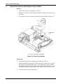
Power Entry Module (PEM) Removal/Replacement ........................
6.8
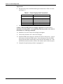
Power Supply Removal/Replacement..............................................
6.9
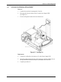
Cooling Fan Removal/Replacement ................................................
6.10
Display PCB Removal/Replacement................................................
6.11
User Interface PCB Removal/Replacement.....................................
6.12
Alarm Speaker Removal/Replacement ............................................
SECTION 7: Spare Parts....................................................................................
7.1
Introduction.......................................................................................
SECTION 8: Packing For Shipment..................................................................
8.1
Introduction.......................................................................................
i
iii
iii
1-1
1-1
1-1
1-5
2-1
2-1
2-1
2-1
3-1
3-1
3-1
3-1
3-10
4-1
4-1
4-1
4-1
4-1
4-8
5-1
5-1
5-1
5-1
5-1
5-1
5-2
5-2
5-6
6-1
6-1
6-1
6-2
6-3
6-4
6-5
6-6
6-7
6-9
6-10
6-11
6-13
7-1
7-1
8-1
8-1
i
Table of Contents
8.2
General Instructions..........................................................................
8.3
Repacking in Original Carton............................................................
8.4
Repacking in a Different Carton........................................................
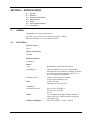
SECTION 9: Specifications................................................................................
9.1
General .............................................................................................
9.2
Electrical............................................................................................
9.3
Physical Characteristics....................................................................
9.4
Environmental ...................................................................................
9.5
Alarms ...............................................................................................
9.6
Factory Default Settings....................................................................
9.7
Performance .....................................................................................
SECTION 10: Data Port Interface Protocol ......................................................
10.1
Introduction .......................................................................................
10.2
Configuring the Data Port .................................................................
10.3
Connecting to the Data Port .............................................................
10.4
Communications with a PC...............................................................
10.5
Using Data on ohe PC ......................................................................
10.6
Real-Time Printout ............................................................................
10.7
Trend Data Printout (ASCII Mode)....................................................
10.8
Trend Printout (Graph Mode)............................................................
10.9
Nurse Call .........................................................................................
10.10 Analog Output ...................................................................................
SECTION 11: Technical Supplement ................................................................
11.1
Introduction .......................................................................................
11.2
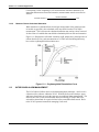
Oximetry Overview............................................................................
11.3
Satseconds Alarm Management.......................................................
11.4
Reads Through Motion .....................................................................
11.5
Circuit Analysis .................................................................................
11.6
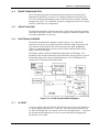
Functional Overview .........................................................................
11.7
AC Input ............................................................................................
11.8
Power Supply PCB ...........................................................................
11.9
Battery...............................................................................................
11.10 User Interface PCB ...........................................................................
11.11 Front Panel Display PCB And Controls ............................................
11.12 Schematic Diagrams.........................................................................
SECTION 12: Index .............................................................................................
ii
8-1
8-2
8-3
9-1
9-1
9-1
9-2
9-2
9-2
9-2
9-3
10-1
10-1
10-1
10-5
10-7
10-8
10-8
10-11
10-12
10-12
10-13
11-1
11-1
11-1
11-2
11-3
11-3
11-3
11-3
11-4
11-5
11-5
11-8
11-9
12-1
Table of Contents
LIST OF FIGURES
Figure 1-1:
Figure 1-2:
Figure 1-3:
Figure 1-4:
Figure 1-5:
Figure 3-1:
Figure 3-2:
Figure 3-3:
Figure 3-4:
Figure 3-5:
Figure 3-6:
Figure 3-7:
Figure 3-8:
Figure 3-9:
Figure 4-1:
Figure 4-2:
Figure 4-3:
Figure 4-4:
Figure 4-5:
Figure 4-6:
Figure 4-7:
Figure 4-8:
Figure 4-9:
Figure 4-10:
Figure 4-11:
Figure 4-12:
Figure 4-13:
Figure 4-14:
Figure 4-15:
Figure 4-16:
Figure 6-1:
Figure 6-2:
Figure 6-3:
Figure 6-4:
Figure 6-5:
Figure 6-6:
Figure 6-7:
Figure 6-8:
Figure 6-9:
Figure 6-10:
Figure 7-1:
Figure 8-1:
Figure 10-1:
Figure 10-2:
Figure 10-3:
Figure 10-4:
Figure 10-5:
Figure 10-6:
Figure 11-1:
Figure 11-2:
Figure 11-3:
N-395 Front Panel ............................................................................. 1-2
N-395 Rear Panel.............................................................................. 1-2
Limits Softkey Map ............................................................................ 1-3
Trend Softkey Map ............................................................................ 1-3
Setup Softkey Map ............................................................................ 1-4
N-395 Controls .................................................................................. 3-2
Self-Test Display ............................................................................... 3-2
Blip (Magnified) View......................................................................... 3-3
Adjusting %SpO2 Upper Alarm Limit ................................................ 3-3
Adjusting % SpO2 Lower Alarm Limit ............................................... 3-4
Adjusting High Pulse Rate Alarm ...................................................... 3-4
Adjusting Low Pulse Rate Alarm ....................................................... 3-4
SatSeconds Alarm............................................................................. 3-5
Data Port Pinouts .............................................................................. 3-8
Service Function Softkeys................................................................. 4-2
Service Function Softkey Map........................................................... 4-2
PARAM Softkeys ............................................................................... 4-3
PRINT Softkeys ................................................................................. 4-4
Trend Printout.................................................................................... 4-4
Errlog Printout.................................................................................... 4-5
Instat Printout .................................................................................... 4-5
INFO Printout..................................................................................... 4-6
NEXT Softkeys .................................................................................. 4-6
ALARMS Softkeys ............................................................................. 4-6
Service Function Softkeys................................................................. 4-7
Service Function NEXT Softkey ........................................................ 4-7
Service Function ALARMS Softkey................................................... 4-7
Service Function Softkeys................................................................. 4-8
PARAM Softkeys ............................................................................... 4-9
SAVE Softkeys .................................................................................. 4-9
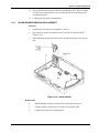
Fuse Removal ................................................................................... 6-2
N-395 Corner Screws........................................................................ 6-3
Separating Case Halves.................................................................... 6-4
N-395 Battery .................................................................................... 6-5
Power Entry Module .......................................................................... 6-6
Power Supply .................................................................................... 6-7
Cooling Fan ....................................................................................... 6-9
Display PCB .................................................................................... 6-10
User Interface PCB ......................................................................... 6-12
Alarm Speaker................................................................................. 6-13
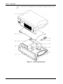
N-395 Expanded View....................................................................... 7-2
Repacking the N-395......................................................................... 8-2
Data Port Softkeys .......................................................................... 10-1
SpaceLabs Connection ................................................................... 10-3
Data Port Pin Layout ....................................................................... 10-6
Real-Time Printout .......................................................................... 10-9
Trend Data Printout (ASCII Mode) ................................................ 10-11
Trend Data Printout (GRAPH MODE)........................................... 10-12
Oxyhemoglobin Dissociation Curve ................................................ 11-2
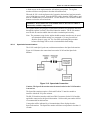
N-395 Functional Block Diagram .................................................... 11-3
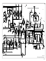
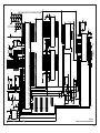
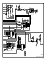
Linear Power Supply Schematic ..................................................... 11-9
iii
Table of Contents
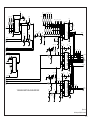
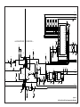
Figure 11-4: 404 Analog Front End Schematic ................................................... 11-9
Figure 11-5: 404 Analog Front End and Pre-Amp Schematic............................. 11-9
Figure 11-6: 404 Analog and Digital Schematic.................................................. 11-9
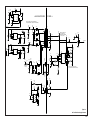
Figure 11-7: 404 DSP Core and Communication Schematic.............................. 11-9
Figure 11-8: 404 Front End to 331 Core Communication Schematic ................. 11-9
Figure 11-9: 404 Front End Power Supplies Schematic ..................................... 11-9
Figure 11-10: SIP/SOP Interface Schematic........................................................ 11-9
Figure 11-11: SIP/SOP Interface Schematic........................................................ 11-9
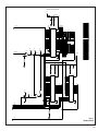
Figure 11-12: MC331 CPU Core Schematic ........................................................ 11-9
Figure 11-13: MC331 Memory Schematic ........................................................... 11-9
Figure 11-14: Contrast and Sound Schematic ..................................................... 11-9
Figure 11-15: Power Supply Schematic............................................................... 11-9
Figure 11-16: Display Interface and Drivers Schematic....................................... 11-9
LIST OF TABLES
Table 3-1:
Table 5-1:
Table 5-2:
Table 5-3:
Table 5-4:
Table 5-5:
Table 5-6:
Table 5-7:
Table 6-1:
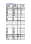
Table 7-1:
Table 9-1:
Table 9-2:
Table 10-1:
Table 10-2:
Table 10-3:
Table 10-4:
iv
Dynamic Operating Range.................................................................. 3-8
Problem Categories ............................................................................ 5-2
Power Problems.................................................................................. 5-3
Button Problems.................................................................................. 5-4
Display/Alarms Problems .................................................................... 5-4
Operational Performance Problems.................................................... 5-5
Data Port Problems............................................................................. 5-6
Error Codes......................................................................................... 5-6
Power Supply Lead Connections........................................................ 6-8
Parts List ............................................................................................. 7-1
Factory Default Settings (Adult) .......................................................... 9-2
Factory Default Settings (Neonate)..................................................... 9-3
Data Port Pin Outs ............................................................................10-6
Printout Codes ................................................................................10-11
Nurse Call Relay Pin States............................................................10-12
Rating of Nurse Call Relay..............................................................10-13
SECTION 1: INTRODUCTION
1.1
1.2
1.3
1.1
Manual Overview
Description of N-395 Pulse Oximeter
Related Documents
MANUAL OVERVIEW
The latest version of this manual is available on the Internet at:
http://www.mallinckrodt.com/respiratory/resp/Serv_Supp/ProductManuals.html
This manual contains information for servicing the Nellcor model N-395 pulse
oximeter. Only qualified service personnel should service this product. Before
servicing the N-395, read the operator’s manual carefully for a thorough
understanding of operation.
WARNING: Explosion hazard. Do not use the N-395 pulse oximeter in the
presence of flammable anesthetics.
1.2
DESCRIPTION OF N-395 PULSE OXIMETER
The N-395 pulse oximeter is indicated for the continuous non-invasive monitoring of
functional oxygen saturation of arterial hemoglobin (SpO2) and pulse rate. The
N-395 is intended for use with neonatal, pediatric, and adult patients during both
no-motion and motion conditions and for patients who are well or poorly perfused, in
hospitals, hospital-type facilities, intra-hospital transport, and home environments.
For prescription use only.
Note:
“Hospital type” environments include surgicenters (including physician
office based facilities, sleep labs, and skilled nursing facilities). Use with
any particular patient requires the selection of an appropriate oxygen
transducer as described in the operator’s manual. Motion performance
claims are applicable to Nellcor models D-25, N-25, I-20, D-20, and D-25L
oximetry sensors.
Through the use of the four softkeys, the operator can access trend information, select
an alarm limit to be changed, choose the language to be used, adjust the internal time
clock, and change communications protocol. The N-395 can operate on AC power or
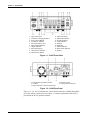
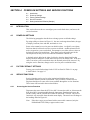
on an internal battery. The controls and indicators for the N-395 are illustrated in
Figure 1-1 and Figure 1-2.
1-1
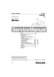
Section 1: Introduction
1. SpO2 Sensor Port
2. AC/Battery Charging Indicator
3. Power On/Off Button
4. Low Battery Indicator
5. Waveform Display Area
6. SatSeconds™ Indicator
7. %SpO2 Indicator
8. Pulse Rate Display
9. Alarm Silence Indicator
10. Alarm Silence Button
11. Adjust Up Button
12. Adjust Down Button
13. Neonate Indicator
14. Contrast Button
15. Softkeys
16. Menu Bar
17. Motion Indicator
18. Pulse Search Indicator
19. Speaker
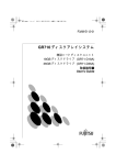
Figure 1-1: N-395 Front Panel
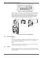
1. Equipotential (ground) Terminal
2. AC Inlet
3. DB-15 Interface Connector (Data Port)
4. Fuse Receptacle
5. Voltage Selection Switch
Figure 1-2: N-395 Rear Panel
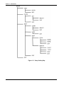
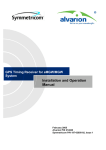
Figures 1-3, 1-4, and 1-5 illustrate the various functions that are available through the
use of the softkeys, and how to access them. A complete explanation of the keys is
provided in the N-395 operator's manual.
1-2
Section 1: Introduction
Figure 1-3: Limits Softkey Map
Figure 1-4: Trend Softkey Map
1-3
Section 1: Introduction
Figure 1-5: Setup Softkey Map
1-4
Section 1: Introduction
1.3
RELATED DOCUMENTS
To perform test and troubleshooting procedures, and to understand the principles of
operation and circuit analysis sections of this manual, you must know how to operate
the monitor. Refer to the N-395 operator’s manual. To understand the various
Nellcor sensors that work with the monitor, refer to the individual sensor’s directions
for use.
The latest version of this manual and Nellcor Sensor’s directions for use are available
on the Internet at:
http://www.mallinckrodt.com/respiratory/resp/Serv_Supp/ProductManuals.html
1-5
(Blank Page)
SECTION 2: ROUTINE MAINTENANCE
2.1
2.2
2.3
2.1
Cleaning
Periodic Safety and Functional Checks
Battery
CLEANING
Caution: Do not immerse the N-395 or its accessories in liquid or clean with
caustic or abrasive cleaners. Do not spray or pour any liquid on the monitor or
its accessories.
To clean the N-395, dampen a cloth with a commercial, nonabrasive cleaner and
wipe the exterior surfaces lightly. Do not allow any liquids to come in contact with
the power connector, fuse holder, or switches. Do not allow any liquids to penetrate
connectors or openings in the instrument cover. Wipe sensor cables with a damp
cloth. For sensors, follow each sensor's directions for use.
2.2
PERIODIC SAFETY AND FUNCTIONAL CHECKS
The following checks should be performed at least every 2 years by qualified service
technicians.
2.3
1.
Inspect the exterior of the N-395 equipment for damage.
2.
Inspect the safety labels for legibility. If the labels are not legible, contact
Nellcor Technical Services Department or your local Nellcor representative.
3.
Verify that the unit performs properly as described in paragraph 3.3.
4.
Perform the electrical safety tests detailed in paragraph 3.4. If the unit fails
these electrical safety tests, repair the unit or contact Nellcor Technical Services
Department or your local Nellcor representative for assistance.
5.
Inspect the fuses for proper value and rating (F1 & F2 = 0.5 amp slow blow).
BATTERY
Nellcor recommends replacing the instrument's battery every 2 years. When the N395 is going to be stored for 3 months or more, remove the battery prior to storage.
To replace or remove the battery, refer to Section 6, Disassembly Guide.
If the N-395 has been stored for more than 30 days, charge the battery as described in
paragraph 3.3.1. A fully discharged battery requires 14 hours with the monitor in
standby, or 18 hours if it is in use, to receive a full charge. The battery is being
charged whenever the instrument is plugged into AC.
Note:
If power stored in the battery is too low, the unit will not operate even when
plugged into AC. If this occurs, leave the unit plugged in to allow the battery
to charge as described in paragraph 3.3.1. After approximately 10 minutes,
the battery should have enough charge to allow the unit to operate on AC.
2-1
(Blank Page)
SECTION 3: PERFORMANCE VERIFICATION
3.1
3.2
3.3
3.4
3.1
Introduction
Equipment Needed
Performance Tests
Safety Tests
INTRODUCTION
This section discusses the tests used to verify performance following repairs or
during routine maintenance. All tests can be performed without removing the N-395
cover. All tests except the battery charge and battery performance tests must be
performed as the last operation before the monitor is returned to the user.
If the N-395 fails to perform as specified in any test, repairs must be made to correct
the problem before the monitor is returned to the user.
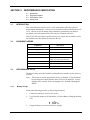
3.2
EQUIPMENT NEEDED
Equipment
3.3
Description
Digital multimeter (DMM)
Fluke Model 87 or equivalent
Durasensor ® oxygen transducer
DS-100A
Oxisensor ® II oxygen transducer
D-25
Pulse oximeter tester
SRC-2
Safety analyzer
Must meet current AAMI ES1/1993
& IEC 601-1/1998 specifications
Sensor extension cable
SCP-10 or MC-10
Data interface cable
EIA-232 cable (optional)
Stopwatch
Manual or electronic
PERFORMANCE TESTS
The battery charge procedure should be performed before monitor repairs whenever
possible.
Note:
3.3.1
This section is written using Nellcor factory-set defaults. If your institution
has preconfigured custom defaults, those values will be displayed. Factory
defaults can be restored. Refer to paragraph 4.4.3, PARAM, subparagraph
RESET.
Battery Charge
Perform the following procedure to fully charge the battery.
1.
Connect the monitor to an AC power source.
2.
Verify that the monitor is off and that the AC Power/Battery Charging indicator
is lit.
3.
Charge the battery for at least 14 hours in standby.
3-1
Section 3: Performance Verification
3.3.2
Power-Up Performance
The power-up performance tests (3.3.2.1 through 3.3.2.2) verify the following
monitor functions:
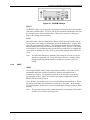
• 3.3.2.1 Power-On Self-Test
• 3.3.2.2 Power-On Defaults and Alarm Limit Ranges
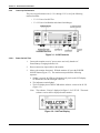
Figure 3-1: N-395 Controls
3.3.2.1
Power-On Self-Test
1.
Connect the monitor to an AC power source and verify that the AC
Power/Battery Charging indicator is lit.
2.
Do not connect any input cables to the monitor.
3.
Observe the monitor front panel. With the monitor off, press the POWER
ON/OFF button (Figure 3-1). The monitor must perform the following
sequence:
a. Within 2 seconds, all LEDs are illuminated, all pixels on the LCD display
are illuminated, and the backlight comes on.
b. The indicators remain lighted.
c. The LCD display shows NELLCOR and the software version of the N-395
(Figure 3-2).
Note:
The software “Version” displayed in Figure 3-2 is X.X.X.X. The actual
software version will be displayed on the monitor.
Figure 3-2: Self-Test Display
3-2
Section 3: Performance Verification
d. A 1-second beep sounds, indicating proper operation of the speaker, and all
indicators turn off except the AC Power/Battery Charging indicator and the
LCD screen.
e. The N-395 begins normal operation.
3.3.2.2
Power-On Defaults and Alarm Limit Ranges
Note:
When observing or changing alarm limits, a 10-second timeout is in effect.
If no action is taken within 10 seconds, the monitor automatically returns to
the monitoring display.
Note:
The descriptions that follow are based on the assumption that Pleth view is
the view that has been selected. The steps for changing an alarm limit are the
same if the view being used is Blip (Magnified) view (Figure 3-3).
Figure 3-3: Blip (Magnified) View
Note:
1.
Power-on defaults will be the factory-set defaults or the defaults set by your
institution.
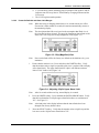
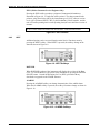
Ensure that the monitor is on. Press and release the LIMITS softkey. Verify
that the monitor emits a single beep and the pleth view is replaced with a display
of the alarm limits. The upper alarm limit for %SpO2 will indicate an alarm
limit of "100" inside a box (Figure 3-4).
Figure 3-4: Adjusting %SpO2 Upper Alarm Limit
Note:
2.
Press the LIMITS softkey. Press and hold the DOWN ARROW button. Verify
that the boxed number for %SpO2 upper alarm limit reduces to a minimum of
"85." See Figure 3-5.
Note:
3.
After 10 seconds with no activity, normal display is resumed.
A decimal point in the display indicates that the alarm limits have been
changed from factory default values.
Press the SELECT softkey. Verify that the monitor emits a single beep and the
box moves to the %SpO2 lower alarm limit of "85."
3-3
Section 3: Performance Verification
Figure 3-5: Adjusting % SpO2 Lower Alarm Limit
4.
Press and hold the DOWN ARROW button and verify that the %SpO2 lower
alarm limit display reduces to a minimum of "20." Press and hold the UP
ARROW button and verify that the %SpO2 lower alarm limit display cannot be
raised past the upper alarm limit setting of "85." Press the EXIT softkey.
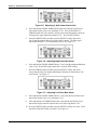
5.
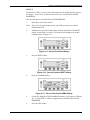
Press the LIMITS softkey and then press the SELECT softkey three times.
Verify that the monitor emits a beep after each keystroke. The Pulse upper
alarm limit should be "170" and should be boxed. See Figure 3-6.
Figure 3-6: Adjusting High Pulse Rate Alarm
6.
Press and hold the DOWN ARROW button. Verify that the minimum displayed
value is "40" for the Pulse upper alarm limit. Press the EXIT softkey.
7.
Press the LIMITS softkey and then press the SELECT softkey four times.
Verify that the Pulse lower alarm limit display indicates an alarm limit of "40"
and is boxed. See Figure 3-7.
Figure 3-7: Adjusting Low Pulse Rate Alarm
8.
Press and hold the DOWN ARROW button. Verify that the boxed Pulse lower
alarm limit display reduces to a minimum of "30."
9.
Press and hold the UP ARROW button and verify that the boxed Pulse lower
alarm limit display cannot be adjusted above the Pulse high limit of "40."
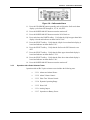
10. Press the LIMITS softkey and then press the SELECT softkey two times. Verify
that SatSeconds SECS alarm is selected. See Figure 3-8.
3-4
Section 3: Performance Verification
Figure 3-8: SatSeconds Alarm
11. Press the UP ARROW button repeatedly and verify that the SatSeconds alarm
display cycles from OFF through 10, 25, 50, 100, OFF.
12. Press the POWER ON/OFF button to turn the monitor off.
13. Press the POWER ON/OFF button to turn the N-395 back on.
14. Press and release the LIMITS softkey. Verify that the %SpO2 upper alarm limit
display is boxed and indicates an alarm limit of "100."
15. Press the SELECT softkey. Verify that the %SpO2 lower alarm limit display is
boxed and indicates an alarm limit of "85."
16. Press the SELECT softkey. Verify that the SatSeconds SECS alarm is set to
OFF.
17. Press the SELECT softkey. Verify that the Pulse upper alarm limit display is
boxed and indicates an alarm limit of "170."
18. Press the SELECT softkey. Verify that the Pulse lower alarm limit display is
boxed and indicates an alarm limit of "40."
19. Press the POWER ON/OFF button to turn the monitor off.
3.3.3
Operation with a Pulse Oximeter Tester
Operation with an SRC-2 pulse oximeter tester includes the following tests:
•
3.3.3.1 Alarms and Alarm Silence
•
3.3.3.2 Alarm Volume Control
•
3.3.3.3 Pulse Tone Volume Control
•
3.3.3.4 Dynamic Operating Range
•
3.3.3.5 Nurse Call
•
3.3.3.6 Analog Output
•
3.3.3.7 Operation on Battery Power
3-5
Section 3: Performance Verification
3.3.3.1
Alarms and Alarm Silence
1.
Connect the SRC-2 pulse oximeter tester to the sensor-input cable and connect
the cable to the monitor. Set the SRC-2 as follows:
SWITCH
POSITION
RATE
LIGHT
MODULATION
RCAL/MODE
38
LOW
OFF
RCAL 63/LOCAL
2.
Press the POWER ON/OFF button to turn the monitor on. After the normal
power-up sequence, press the following softkeys: SETUP, VIEW, and PLETH.
Verify that the %SpO2 and Pulse initially indicate zeroes.
3.
Move the modulation switch on the SRC-2 to LOW.
4.
Verify the following monitor reactions:
a.
b.
c.
d.
e.
5.
Press and hold the ALARM SILENCE button on the front of the monitor for less
than 3 seconds. Verify that the %SpO2 display indicates "60" and the Pulse
display indicates "SEC" while the ALARM SILENCE button is pressed. When
the button is released, the alarm is silenced.
6.
With the alarm silenced, verify the following:
a.
b.
c.
d.
e.
3-6
The plethysmograph waveform begins to track the artificial pulse signal
from the SRC-2.
The pulse tone is heard.
Zeroes are displayed in the %SpO2 and Pulse displays.
Within 20 seconds, the monitor displays saturation and pulse rate as
specified by the tester. Verify that the values are within the following
tolerances:
Oxygen Saturation Range
79% to 83%
Pulse Rate Range
37 to 39 bpm
The audible alarm sounds and both the %SpO2 and Pulse displays flash,
indicating that both parameters have violated the default alarm limits.
The alarm remains silenced for 60 seconds.
The Alarm Silence indicator lights.
The %SpO2 and Pulse displays continue to flash.
The pulse tone is still audible.
The audible alarm returns in approximately 60 seconds.
7.
Press and hold the ALARM SILENCE button. Within 3 seconds, press the
DOWN ARROW button until the Pulse Rate display indicates "30." Press the
UP ARROW button and verify that the displays indicate 60 SEC, 90 SEC, 120
SEC, and OFF. Release the button when the display indicates "OFF."
8.
Press and release the ALARM SILENCE button. Verify that the Alarm Silence
Indicator flashes.
Section 3: Performance Verification
9.
3.3.3.2
Wait approximately 3 minutes. Verify that the alarm does not return. After 3
minutes, the alarm silence reminder beeps three times, and will continue to do so
at approximately 3-minute intervals.
Alarm Volume Control
After completing the procedure in paragraph 3.3.3.1:
1.
Press and hold the ALARM SILENCE button and verify the following:
a.
b.
3.3.3.3
3.3.3.4
"OFF" is displayed for approximately 3 seconds.
After 3 seconds, a steady tone is heard at the default alarm volume setting,
the %SpO2 display indicates "VOL," and the Pulse Rate display indicates
the default setting of 5.
2.
While still pressing the ALARM SILENCE button, press the DOWN ARROW
button until an alarm volume setting of 1 is displayed. Verify that the volume of
the alarm has decreased but is still audible.
3.
Continue pressing the ALARM SILENCE button and press the UP ARROW
button to increase the alarm volume setting to a maximum value of 10. Verify
that the volume increases. Press the DOWN ARROW button until a
comfortable audio level is attained.
4.
Release the ALARM SILENCE button. The tone will stop.
Pulse Tone Volume Control
1.
Press the UP ARROW button and verify that sound level of the beeping pulse
tone increases.
2.
Press the DOWN ARROW button and verify that sound level of the beeping
pulse tone decreases until it is no longer audible. Press the UP ARROW button
to return the beep volume to a comfortable level.
Dynamic Operating Range
The following test sequence verifies proper monitor operation over a range of input
signals.
1.
Connect the SRC-2 to either the SCP-10 or MC-10 sensor cable, which is
connected to the N-395 and turn the N-395 on.
2.
Place the SRC-2 in the RCAL 63/LOCAL mode.
3.
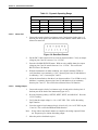
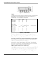
Set the SRC-2 as indicated in Table 3-1. Verify that the N-395 readings are
within the indicated tolerances. Allow the monitor several seconds to stabilize
the readings.
Note:
An asterisk (*) indicates values that produce an alarm. Press the ALARM
SILENCE button to silence the alarm.
3-7
Section 3: Performance Verification
Table 3-1: Dynamic Operating Range
SRC-2 Settings
3.3.3.5
N-395 Indications
RATE
LIGHT
MODULATION
SpO2
Pulse Rate
38
HIGH2
LOW
79 - 83*
35 - 41*
112
HIGH1
HIGH
79 - 83*
109 - 115
201
LOW
LOW
79 - 83*
198 - 204*
201
LOW
HIGH
79 - 83*
198 - 204*
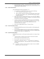
Nurse Call
1.
Connect the negative lead of a voltmeter to pin 5 and positive lead to pin 11 of
the data port on the back of the instrument. Ensure that the audible alarm is not
silenced or turned off.
Figure 3-9: Data Port Pinouts
3.3.3.6
2.
Set the SRC-2 Rate switch to 201 to create an alarm condition. Verify an output
voltage at pins 5 and 11 between +5 to +12 VDC.
3.
Press the ALARM SILENCE button. With no active audible alarm, the output
voltage at pins 5 and 11 must be between -5 to -12 VDC. This verifies the
RS-232 Nurse Call function.
4.
With the instrument in an alarm condition, use a digital voltmeter (DVM) to
verify that there is no continuity (≥ 1 MΩ) between pins 8 and 15 and that there
is continuity (≤ 60 Ω) between pins 7 and 15.
5.
Adjust the alarm limits so that there is no alarm condition. Use a DVM to verify
that there is continuity between pins 8 and 15 and that there is not continuity
between pins 7 and 15. This verifies the solid state Nurse Call function.
Analog Output
1.
Connect the negative lead of a voltmeter to pin 10 and positive lead to pin 6 of
the data port on the back of the instrument (Figure 10-3).
2.
Press the following softkeys: SETUP, NEXT, NEXT, and ANALOG. Press the
1-VOLT softkey.
3.
Verify that the output voltage is +1.0 ± 0.025 VDC. This verifies the analog
SpO2 function.
4.
Leave the negative lead connected to pin 10 and verify 1.0 ± 0.025 VDC on pins
13 and 14. This verifies the BPM and Pleth function.
Note:
5.
3-8
If step 4 takes more than 2 minutes to complete, the analog output will time
out. Repeat step 2 to initiate the analog output.
Move the positive lead back to pin 6.
Section 3: Performance Verification
6.
Press the following softkeys; SETUP, NEXT, NEXT, and ANALOG. Press the
0-VOLT softkey.
7.
Verify that the output voltage is +0.0 ± 0.025 VDC.
8.
Leave the negative lead connected to pin 10 and verify 0.0 ± 0.025 VDC on pins
13 and 14.
Note:
9.
3.3.3.7
Disconnect the voltmeter from the instrument.
Operation on Battery Power
1.
With the instrument operating on AC, turn on the backlight.
2.
Disconnect the instrument from AC and verify that the AC/Battery Charging
indicator turns off.
3.
Verify that the instrument continues monitoring normally and that the low
battery indicator is not lit.
Note:
4.
3.3.4
If step 8 takes more than 2 minutes to complete, the analog output will time
out. Repeat step 2 to initiate the analog output.
If the low battery indicator is illuminated, perform the procedure outlined in
step 3.3.1.
Connect the instrument to AC and verify that the AC/Battery Charging indicator
turns on and that the instrument is monitoring normally.
General Operation
The following tests are an overall performance check of the system:
3.3.4.1
•
3.3.4.1 LED Excitation Test
•
3.3.4.2 Operation with a Live Subject
LED Excitation Test
This procedure uses normal system components to test circuit operation. A Nellcor
Oxisensor ® II oxygen transducer, model D-25, is used to examine LED intensity
control. The red LED is used to verify intensity modulation caused by the LED
intensity control circuit.
1.
Connect the monitor to an AC power source.
2.
Connect an SCP-10 or MC-10 sensor input cable to the monitor.
3.
Connect a D-25 sensor to the sensor-input cable.
4.
Press the POWER ON/OFF button to turn the monitor on.
5.
Leave the sensor open with the LEDs and photodetector visible.
6.
After the monitor completes its normal power-up sequence, verify that the
sensor LED is brightly lit.
7.
Slowly move the sensor LED in proximity to the photodetector element of the
sensor. Verify as the LED approaches the optical sensor, that the LED intensity
decreases.
8.
Open the sensor and notice that the LED intensity increases.
3-9
Section 3: Performance Verification
9.
Repeat step 7 and the intensity will again decrease. This variation is an
indication that the microprocessor is in proper control of LED intensity.
10. Turn the N-395 off.
3.3.4.2
Operation with a Live Subject
Patient monitoring involves connecting the monitor to a live subject for a qualitative
test.
3.4
1.
Ensure that the monitor is connected to an AC power source.
2.
Connect an SCP-10 or MC-10 sensor input cable to the monitor.
3.
Connect a Nellcor Durasensor ® oxygen transducer, model DS-100A, to the
sensor input cable.
4.
Clip the DS-100A to the subject as recommended in the sensor's directions for
use.
5.
Press the POWER ON/OFF button to turn the monitor on and verify that the
monitor is operating.
6.
The monitor should stabilize on the subject's physiological signal in about 15 to
30 seconds. Verify that the oxygen saturation and pulse rate values are
reasonable for the subject.
SAFETY TESTS
N-395 safety tests meet the standards of, and are performed in accordance with,
IEC 601-1 (EN 60601-1, Amendment 1, Amendment 2) and UL 2601-1, for
instruments classified as Class 1 and TYPE BF and ANSI/AAMI Standard ESI.
Applicable tests for these standards are listed below. The technician must be familiar
with the Standards applicable to their institution and country. Test equipment and its
application must comply with the applicable standard.
•
Ground Integrity
•
Earth Leakage Current
•
Enclosure Leakage Current
•
Patient Applied Risk Current
•
Patient Isolation Risk Current
Note:
3-10
Patient Applied Risk Current and Patient Isolation Risk Current. The
leakage test lead from the test equipment must be connected to the N-395
SpO2 Sensor Port using a male 9-pin “D” type connector that has all pins
shorted together.
SECTION 4: POWER-ON SETTINGS AND SERVICE FUNCTIONS
4.1
4.2
4.3
4.4
4.5
4.1
Introduction
Power-on Settings
Factory Default Settings
Service Functions
Setting Institutional Defaults (Sample)
INTRODUCTION
This section discusses how to reconfigure power-on default values, and access the
service functions.
4.2
POWER-ON SETTINGS
The following paragraphs describe how to change power-on default settings.
By using softkeys as shown in Figure 1-1, the user can change alarm limits, the type
of display, baud rate, time and date, and trends to view.
Some values cannot be saved as power-on default values. An SpO2 Lower Alarm
limit less than 80 will not be saved as a power-on default. Audible Alarm Off will
not be accepted as a power-on default. An attempt to save either of these values as
default will result in an invalid tone. These limits can be adjusted lower for the
current patient, but they will be lost when the instrument is turned off.
A decimal point is added to the right of a display when the alarm limit for that
display has been changed to a value that is not a power-on default value. If the new
value is saved as a power-on default value, the decimal point will be removed. By
using the service functions, changes can be saved as power-on default values.
4.3
FACTORY DEFAULT SETTINGS
Factory power-on default settings for the N-395 are listed in Table 9-1 on page
9-2and Table 9-2 on page 9-3.
4.4
SERVICE FUNCTIONS
Service functions can be used to select institutional defaults and to access
information about the patient or instrument. Only a Nellcor Customer Service
Engineer should access some of the items available through the service functions.
These items will be noted in the text that follows.
4.4.1
Accessing the Service Functions
Disconnect the sensor from the SCP-10 or MC-10 extension cable; or, disconnect the
SCP-10 or MC-10 extension cable from the instrument. Simultaneously press the
LIGHT softkey and the CONTRAST button for more than 3 seconds. The service
function is only accessible from the main menu display. The menu bar will change to
the headings listed in Figure 4-1.
Note:
If the above steps are performed with a sensor cable connected, only the
PARAM and EXIT softkeys appear on the screen.
4-1
Section 4: Power-On Settings and Service Functions
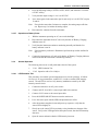
Figure 4-1: Service Function Softkeys
Figure 4-2 can be used as a quick reference showing how to reach different softkey
functions. Each gray box represents a different set of softkeys that can be reached
with the service function. Items reached through the PARAM softkey can be
accessed during normal operation. Functions provided by the PRINT and NEXT
softkeys cannot be accessed when a sensor cable is connected to the instrument.
Each of the various functions is described in the text that follows.
PARAM
PRINT
NEXT
RESET
SAVE
EXIT
TREND
ERRLOG
INSTAT
INFO
DOWNLD
ALARMS
NEXT
EXIT
RESET
DEFAULTS
YES
NO
EXIT
To User Softkeys
SELECT
EXIT
SAVE
DEFAULTS
YES
NO
RESET
SAVE
EXIT
Figure 4-2: Service Function Softkey Map
4.4.2
EXIT & NEXT Softkeys
NEXT
There are not enough softkeys to display all of the options that are available at some
levels of the menu. Pressing the NEXT softkey allows you to view additional
options available at a given menu level.
EXIT
To back up one menu level, press the EXIT softkey. The service functions can be
exited by repeatedly pressing the EXIT softkey.
4.4.3
PARAM
When the PARAM softkey is pressed, the function of the softkeys changes as shown
in Figure 4-3. These options can be accessed without disconnecting the sensor cable
from the instrument.
4-2
Section 4: Power-On Settings and Service Functions
Figure 4-3: PARAM Softkeys
RESET
The RESET softkey can be used if any settings stored in memory have been changed
from factory default values. If YES is pressed, the instrument sounds three tones and
the settings return to factory default values. When NO is pressed, no changes are
made to the settings stored in memory.
SAVE
When adjustable values are changed from factory default, the SAVE softkey can be
used to preserve the settings as institutional power-on default values. Pressing YES
stores the current settings in memory. The instrument sounds three tones indicating
that the changes have been saved as power-on default values. The new saved values
will continue to be used through power-on and off cycles until they are changed and
saved again, or until they are reset. If NO is pressed, the changed values will not be
saved.
Note:
4.4.4
An invalid tone indicates a parameter value cannot be saved as a power-on
default (see paragraph 4.2). Along with the invalid tone, a message will be
displayed indicating which parameter could not be saved as a power-on
default.
PRINT
PRINT
Accessing the PRINT softkey makes four printouts available. See Section 10 for
information about how to make connections to the data port and how data is
presented in a printout. The appropriate printout can be selected by pressing the
corresponding softkey. Figure 4-4 represents the softkey configuration after the
PRINT softkey has been selected.
Up to 48 hours of trend data can be viewed on the printouts described below. When
the instrument is turned on, trend data is recorded every 4 seconds. As an example,
an instrument that is used 6 hours a week would take approximately 8 weeks to fill its
memory.
Note:
The two-letter codes and the symbols that occur in the printout are described
in Table 10-2 of Section 10 on page 10-11.
4-3
Section 4: Power-On Settings and Service Functions
Figure 4-4: PRINT Softkeys
TREND
A Trend printout will include all data recorded for up to 48 hours of monitoring since
the last Delete Trends was performed. A new trend point is recorded every 4
seconds. Figure 4-5 is an example of a Trend printout.
N-395 Version 1.0.0.000
TIME
01-Jul-99 14:00:00
01-Jul-99 14:00:05
01-Jul-99 14:00:10
01-Jul-99 14:00:15
01-Jul-99 18:00:43
01-Jul-99 18:00:48
N-395 Version 1.0.0.000
Time
01-Jul-99 18:00:53
01-Jul-99 18:00:58
01-Jul-99 18:01:03
01-Jul-99 18:01:08
01-Jul-99 18:01:13
Output Complete
TREND
SpO2 Limit: 30-100%
PR (bpm)
PA
120
220
124
220
190
220
190
220
--------Trend
SpO2 Limit: 80-100%
%SpO2
PR (bpm)
PA
------------98
100
140
98
181*
190
99
122
232
PR Limit: 100-180 bpm
%SpO2
100
100
100
100
-----
PR Limit: 60-180 bpm
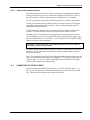
Figure 4-5: Trend Printout
The first row of the printout includes information about the type of instrument
delivering the information, the software level, type of printout, and alarm parameters.
The second line lists the headings for the columns. These lines are printed out every
25 lines, or when a change to an alarm limit is made.
Patient data is represented with a date and time stamp for the data. In the example
above, the "- - -" means that a sensor was connected but the signal quality of the data
being received was too low for the monitor to interpret the data. Patient data that is
outside of an alarm limit is marked with an asterisk (*).
At the end of the printout "Output Complete" will be printed. This indicates that
there was no corruption of data. If the Output Complete statement is not printed at
the end of the printout, the data must be considered invalid.
ERRLOG (Nellcor Customer Service Engineer Only)
A list of all the errors recorded in memory can be obtained by pressing the ERRLOG
softkey. The first line lists the type of instrument producing the printout, software
level, type of printout, and the time of the printout are listed in the first line. The
second line of the printout consists of column headings. If nothing prints out, there
have been no errors. An example of an Errlog printout is shown in Figure 4-6.
4-4
Section 4: Power-On Settings and Service Functions
N-395 Version 1.0.0.000
Op Time
Error
10713:21:03
52
00634:26:01
37
Output Complete
Error Log
Task
12
4
Time:
14600:00:07
Addr Count
48F9 100
31A2 3
Figure 4-6: Errlog Printout
INSTAT (Nellcor Customer Service Engineer Only)
The DELETE softkey, described in the operator's manual, allows the user to delete
the most recent trend data. The current trend data, along with the deleted trends, can
be retrieved from the instrument through an Instat printout.
The oldest deleted trend is Trend 01 on the Instat printout. If a Trend 01 already
exists in memory from an earlier Delete, the next deleted trend will become Trend 02.
Every time a DELETE is performed from the user softkeys, the number of existing
trends will increase by 1. The current trend will have the largest trend number.
Figure 4-7 illustrates an Instat printout. Line one is for instrument type, software
revision level, type of printout, and alarm parameter settings. The second line
contains the column headings. A trend point is recorded for every 4 seconds of
instrument operation. Up to 48 hours of instrument operation data can be recorded.
If the final line on the printout shows "Output Complete," then the data has been
successfully transmitted with no corruption. If there is no "Output Complete" line
printed, the data should be considered invalid.
N-395
Version 1.0.0.000
Instrument
TIME Trend 01
%SpO2 PR (bpm)
01-Jul-99 14:00:00
----01-Jul-99 14:00:05
----01-Jul-99 14:00:10
100
120
01-Jul-99 14:00:15
100
120
N-395
Version 1.0.0.000
Instrument
TIME Trend 02
%SpO2 PR (bpm)
01-Jul-99 14:24:24
79*
58*
01-Jul-99 14:24:29
79*
57*
01-Jul-99 14:24:29
0*
0*
N-395
Version 1.0.0.000
Instrument
TIME Trend 03
%SpO2 PR (bpm)
11-Jul-99 7:13:02
99
132*
11-Jul-99 7:13:07
99
132*
11-Jul-99 7:13:12
99
132*
11-Jul-99 7:13:17
99
132*
11-Jul-99 7:13:22
99
132*
11-Jul-99 7:13:27
99
132*
11-Jul-99 7:13:32
99
132*
Output Complete
SpO2 Limit: 30-100%
PA
SpO2 Status
--SD
--PS
220
220
SpO2 Limit: 80-100%
PA
SpO2 Status
220
PS SL PL
220
PS SL PL
--PS LP SL PL
SpO2 Limit: 80-100%
PA
SpO2 Status
220
PH
220
PH
220
PH
220
PH
220
PH
220
PH
220
PH
PR Limit: 100-180 bpm
UIF Status Aud
BU LB AO L
BU LB AO
BU LB
BU LB
PR Limit: 60-180 bpm
UIF Status Aud
BU LB M
BU LB AS M
BU LB AS H
PR Limit: 60-180 bpm
UIF Status Aud
BU M
BU M
BU M
BU M
BU M
BU M
BU M
Figure 4-7: Instat Printout
4-5
Section 4: Power-On Settings and Service Functions
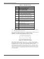
INFO (Nellcor Customer Service Engineer Only)
Pressing the INFO softkey produces a printout of instrument information as
illustrated in Figure 4-8. A single line will be printed. The data presented in the
printout, going from left to right is, the instrument type (N-395), software version
level, type of printout (INFO), CRC (Cyclic Redundancy Check) number, and the
ratio of current operating time to total operating time (the ratio itself has no units of
measure.
N-395 Version XXXXXX INFO CRC:XXXX SEC: 123456789/987654321
Figure 4-8: INFO Printout
4.4.5
NEXT
Additional options can be accessed from the main Service Functions menu by
pressing the NEXT softkey. When NEXT is pressed, the softkeys change to the
functions shown in Figure 4-9.
Figure 4-9: NEXT Softkeys
DOWNLD
When DOWNLD is selected, the instrument will display the revision of the Boot
Code. To exit DOWNLD, cycle power to the instrument by pressing the POWER
ON/OFF button. Consult the Directions for Use (DFU) provided with any
downloads or upgrades to the FLASH firmware.
ALARMS
Pressing the ALARMS softkey can change characteristics of the audible alarm.
When the ALARMS softkey is pressed, the softkey's functions change as shown in
Figure 4-10.
Figure 4-10: ALARMS Softkeys
4-6
Section 4: Power-On Settings and Service Functions
SELECT
The SELECT softkey is used to select what function of the audible alarm is going to
be changed. A box can be cycled between two choices: ALLOW OFF and OFF
REMINDER.
How to select and set ALLOW OFF and OFF REMINDER:
1.
Disconnect sensor from monitor.
Note:
If the sensor is not disconnected, the only softkeys on the screen will be
PARAM and EXIT.
2.
Simultaneously press the fourth softkey from the left and the CONTRAST
softkey for more than 3 seconds. The menu bar will change to the softkey
headings shown in Figure 4-11.
Figure 4-11: Service Function Softkeys
3.
Press the NEXT softkey.
Figure 4-12: Service Function NEXT Softkey
4.
Press the ALARMS softkey.
Figure 4-13: Service Function ALARMS Softkey
5.
Use the UP ARROW or DOWN ARROW buttons to cycle between YES and
NO. Use the SELECT softkey to toggle between ALLOW OFF and OFF
REMINDER.
6.
Press the EXIT softkey.
4-7
Section 4: Power-On Settings and Service Functions
When ALLOW OFF is selected, a choice is given between allowing an audible alarm
OFF or disabling the audible alarm OFF. Pressing the UP or DOWN ARROW key
cycles between Yes and No. If Yes is selected, the operator has the option of
selecting AUDIBLE ALARM OFF. If No is selected, the operator is not given the
option of selecting AUDIBLE ALARM OFF as an alarm silence duration choice.
If the audible alarm is set to Off, a reminder tone can be sounded every 3 minutes to
notify the user of this condition. The UP and DOWN ARROW keys can be used to
change the choice from Yes to No. Selecting Yes enables the Reminder. Selecting
No disables the Reminder when the audible alarm is set to Off.
4.5
SETTING INSTITUTIONAL DEFAULTS (SAMPLE)
The following default values may be set:
•
Alarm Silence Duration (30, 60, 90, 120 seconds)
•
Alarm Silence Restriction (none, sound reminder, do not allow OFF)
•
Alarm Volume (1 to 10)
•
Nurse Call Priority RS-232 (normally high, normally low)
•
Pulse Beep Volume (0 to 10)
•
Pulse Rate Upper Alarm Limit (low limit to 250 bpm)
•
Pulse Rate Lower Alarm Limit (20 bpm to high limit)
•
SatSeconds (OFF, 10, 25, 50, 100)
•
Serial Port Baud Rate (2400, 9600, 19200)
•
Serial Port Mode (ASCII, OXINET, CLINICAL, GRAPH, AGILEN, [Agilent
HP monitor], SPACELB [SpaceLabs monitor], MARQ [GE Marquette
monitor], DATEX [Datex-Ohmeda AS/3 monitor] ). Available selections
depend on the software installed in your N-395.
•
SpO2 Upper Alarm Limit (low limit to 100%)
•
SpO2 Lower Limit (80% to high limit)
1.
Disconnect sensor from monitor.
Note:
If the sensor is not disconnected, the only softkeys on the screen will be
PARAM and EXIT.
2.
Set desired values to the institutional values.
3.
Simultaneously press the LIGHT softkey and the CONTRAST button for
more than 3 seconds. The menu bar will change to the softkey headings
shown in Figure 4-14.
Figure 4-14: Service Function Softkeys
4-8
Section 4: Power-On Settings and Service Functions
4.
Press the PARAM softkey. See Figure 4-15.
Figure 4-15: PARAM Softkeys
5.
Press the SAVE softkey. See Figure 4-16.
Figure 4-16: SAVE Softkeys
6.
The monitor will sound 3 beeps indicating that defaults have been reset.
4-9
(Blank Page)
SECTION 5: TROUBLESHOOTING
5.1
5.2
5.3
5.4
5.5
5.6
5.7
5.8
5.1
Introduction
How to Use this Section
Who Should Perform Repairs
Replacement Level Supported
Returning the N-395
Obtaining Replacement Parts
Troubleshooting Guide
Error Codes
INTRODUCTION
This section explains how to troubleshoot the N-395 if problems arise. Tables are
supplied that list possible monitor difficulties, along with probable causes, and
recommended actions to correct the difficulty.
5.2
HOW TO USE THIS SECTION
Use this section in conjunction with Section 3, Performance Verification, and Section
7, Spare Parts. To remove and replace a part you suspect is defective, follow the
instructions in Section 6, Disassembly Guide. The circuit analysis section in the
Technical Supplement offers information on how the monitor functions.
5.3
WHO SHOULD PERFORM REPAIRS
Only qualified service personnel should open the monitor housing, remove and
replace components, or make adjustments. If your medical facility does not have
qualified service personnel, contact Nellcor Technical Services at 1.800.NELLCOR
or your local Nellcor representative.
5.4
REPLACEMENT LEVEL SUPPORTED
The replacement level supported for this product is to the printed circuit board (PCB)
and major subassembly level. Once you isolate a suspected PCB, follow the
procedures in Section 6, Disassembly Guide, to replace the PCB with a known good
PCB. Check to see if the trouble symptom disappears and that the monitor passes all
performance tests. If the trouble symptom persists, swap back the replacement PCB
with the suspected malfunctioning PCB (the original PCB that was installed when
you started troubleshooting) and continue troubleshooting as directed in this section.
5.5
RETURNING THE N-395
Contact Nellcor Technical Services Department or your local Nellcor representative
for shipping instructions including a Returned Goods Authorization (RGA) number.
Unless otherwise instructed by Nellcor’s Technical Services Department, it is not
necessary to return the sensor or other accessory items with the monitor. Pack the N395 in its original shipping carton. If the original carton is not available, use a
suitable carton with appropriate packing material to protect it during shipping.
Return the N-395 by any shipping method that provides proof of delivery.
5-1
Section 5: Troubleshooting
5.6
OBTAINING REPLACEMENT PARTS
Nellcor’s Technical Services provides technical assistance information and
replacement parts. To obtain replacement parts, contact Nellcor or your local Nellcor
representative. Refer to parts by the part names and part numbers listed in Section 7,
Spare Parts.
The latest version of this manual is available on the Internet at:
http://www.nellcor.com/respiratory/resp/Serv_Supp/ProductManuals.html
5.7
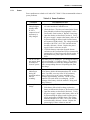
TROUBLESHOOTING GUIDE
Problems with the N-395 are categorized in Table 5-1. Refer to the paragraph
indicated for further troubleshooting instructions.
Note:
Taking the recommended actions discussed in this section will correct the
majority of problems you may encounter. However, problems not covered
here can be resolved by calling Nellcor Technical Services at
1.800.NELLCOR or your local Nellcor representative.
Table 5-1: Problem Categories
Problem Area
1.
2.
Power
•
No power-up on AC and/or DC
•
Fails power-on self-test
•
Powers down without apparent
cause
Buttons
•
3.
4.
5.
5.7.1
5.7.2
Monitor does not respond properly
to buttons
Display/Alarms
•
Displays do not respond properly
•
Alarms or other tones do not sound
properly or are generated without
apparent cause
Operational Performance
•
Displays appear to be operational,
but monitor shows no readings
•
Suspect readings
Data Port
•
Refer to Paragraph
5.7.3
5.7.4
5.7.5
N-395 data port not functioning
properly
All of the categories in Table 5-1 are discussed in the following paragraphs.
5-2
Section 5: Troubleshooting
5.7.1
Power
Power problems are related to AC and/or DC. Table 5-2 lists recommended actions to
power problems.
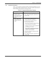
Table 5-2: Power Problems
Condition
Recommended Action
1. Battery Low
indicator lights
steadily while
N-395 is
connected to AC
and battery is
fully charged.
1. Ensure that the N-395 is plugged into an operational
AC outlet and the AC indicator is on.
3. Battery Low
indicator on
during DC
operation and an
alarm is
sounding.
There are 15 minutes or less of usable charge left on the
N-395 battery before the instrument shuts off. At this
point, if possible, cease use of the N-395 on battery
power, connect it to an AC source and allow it to
recharge (approximately 14 hours). The N-395 may
continue to be used while it is recharging. (A full
recharge of the battery while the monitor is being used
takes 18 hours.)
1. Replace battery if it is more than 2 years old.
2. If the battery fails to hold a charge, replace the
battery as indicated in Section 6, Disassembly Guide.
3. Open the monitor as described in Section 6. Verify
the power supply’s output to the battery while on AC
by disconnecting the battery leads from the power
supply and connect a DVM to them. The voltage
measured should be 6.8 VDC ± 0.15 VDC and the
current should be 400 mA ± 80 mA. Replace the
power supply if above values are not met.
2. Check the fuses. The fuses are located in the Power
Entry Module as indicated in paragraph 6.3 of the
Disassembly Guide section 6. Replace if necessary.
3. Open the monitor as described in section 6. Verify
the power supply’s output to the battery while on AC
by disconnecting the battery leads from the battery
and connect a DVM to them. The voltage measured
should be 6.80 VDC ± 0.15 VDC and the current
should be 400 mA ± 80 mA. Replace the power
supply if above values are not met.
4. Check the harness connection from the bottom
enclosure to the User Interface PCB, as instructed in
paragraph 6.11 of the Disassembly Guide section. If
the connection is good, replace the User Interface
PCB.
2. The N-395 does The battery may be discharged. To recharge the battery,
not operate when refer to paragraph 3.3.1, Battery Charge. The monitor
disconnected
may be used with a less than fully charged battery but
from AC power. with a corresponding decrease in operating time from
that charge.
4. Battery does not
charge.
5-3
Section 5: Troubleshooting
5.7.2
Buttons
Table 5-3 lists symptoms of problems relating to non-responsive buttons and
recommended actions. If the action requires replacement of a PCB, refer to Section
6, Disassembly Guide.
Table 5-3: Button Problems
Symptoms
Recommended Action
1. The N-395 turns on but 1. Replace Top Case assembly.
does not respond to
2. If the buttons still do not work, replace interface
some or all of the
PCB.
buttons.
5.7.3
Display/Alarms
Table 5-4 lists symptoms of problems relating to nonfunctioning displays and audible
tones or alarms, and recommended actions. If the action requires replacement of a
PCB or module, refer to Section 6, Disassembly Guide.
Table 5-4: Display/Alarms Problems
Symptoms
1. Display values are
missing or erratic.
Recommended Action
1. If the sensor is connected, replace the sensor
extension cable.
2. If the condition persists, replace the sensor.
3. If the condition still persists, replace the
interface printed circuit board.
2. Display pixels do not
light.
1. Check the connection between the User Interface
PCB and the Display PCB.
2. If the condition does not change, replace the
Display PCB.
3. If the condition still persists, replace the User
Interface PCB.
3. Alarm sounds for no
apparent reason.
1. Moisture or spilled liquids can cause an alarm to
sound. Allow the monitor to dry thoroughly
before using.
2. If the condition persists, replace the User
Interface PCB.
4. Alarm does not sound.
1. Check alarm silence status.
2. Replace the speaker as described in Section 6,
Disassembly Guide.
3. If the condition persists, replace the User
Interface PCB.
5-4
Section 5: Troubleshooting
5.7.4
Operational Performance
Table 5-5 lists symptoms of problems relating to operational performance (no error
codes displayed) and recommended actions. If the action requires replacement of a
PCB or module, refer to Section 6, Disassembly Guide.
Table 5-5: Operational Performance Problems
Symptoms
Recommended Action
1. The Pulse Amplitude
indicator seems to
indicate a pulse, but the
digital displays show
zeroes.
1. The sensor may be damaged; replace it.
2. SpO2 or Pulse values
change rapidly; Pulse
Amplitude indicator is
erratic.
1. The sensor may be damp or may have been
reused too many times. Replace it.
2. If the condition still persists, replace the User
Interface PCB.
2. An electrosurgical unit (ESU) may be
interfering with performance:
− Move the N-395 and its cables and sensors
as far from the ESU as possible.
− Plug the N-395 power supply and the ESU
into different AC circuits.
− Move the ESU ground pad as close to the
surgical site as possible and as far away
from the sensor as possible.
3. Verify the performance with the procedures
detailed in Section 3.
4. If the condition still persists, replace the User
Interface PCB.
5-5
Section 5: Troubleshooting
5.7.5
Data Port
Table 5-6 lists symptoms of problems relating to the data port and recommended
actions. If the action requires replacement of the User Interface PCB, refer to Section
6, Disassembly Guide.
Table 5-6: Data Port Problems
Symptoms
Recommended Action
1. No printout is being
received.
1. The monitor’s baud rate does not match the
printer. Change the baud rate of the monitor
following instructions in paragraph 10.2.
2. If the condition still persists, replace the User
Interface PCB.
2. The RS-232 nurse call is
not working.
1. Verify that connections are made between
pins 5 (GND) and 11 (nurse call) of the data
port. (See Figure 10-3)
2. Verify that the output voltage between
ground pin 5 and pin 11 is -5 to -12 VDC (no
alarm) and +5 to +12 VDC (during alarm).
(See Figure 10-2)
3. If the condition still persists, replace the User
Interface PCB.
5.8
ERROR CODES
An error code is displayed when the N-395 detects a non-correctable failure. When
this occurs, the unit stops monitoring, sounds a low-priority alarm that cannot be
silenced, clears patient data from the display, and displays an error code.
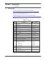
Table 5-7 provides a complete list of error codes and possible solutions.
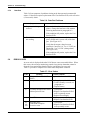
Table 5-7: Error Codes
Code
1
4
5-6
Meaning
Failure of Power-On Self-Test
(POST)
Battery dead
5
Too many microprocessor resets
within a period of time
6
Boot CRC error
8
11
12
Boot CRC Error
Flash ROM corruption
Excessive resets
Possible Solutions
Replace User Interface PCB
1. Charge battery for 14 hours
2. Leads of battery reversed; see
paragraph 6.6.
3. Replace battery
1. Cycle power
2. Replace User Interface PCB if
code 5 repeatedly occurs
3. Replace Power Supply
1. Cycle power
2. Replace User Interface PCB
1. Cycle power
2. Replace User Interface PCB if
code repeatedly occurs
Section 5: Troubleshooting
Table 5-7: Error Codes
Code
52
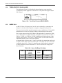
5.8.1
Meaning
Loss of settings
76
Error accessing EPROM
80
Institutional default values lost
and reset to factory default
values
81
Settings lost (settings that were
different from power-on default
values have been lost)
82
Time clock lost
84
Internal communications error
Possible Solutions
1. Cycle power
2. Check and reset settings if
necessary
3. Check battery
4. Replace User Interface PCB
if code repeatedly occurs
1. Cycle power
2. Replace User Interface PCB
1. Cycle power
2. Replace User Interface PCB if
code 80 repeatedly occurs
1. Cycle power
2. Check and reset settings if
necessary
3. Check battery
4. Replace User Interface PCB
if code repeatedly occurs
1. Reset time clock
2. Battery power was lost; check
the battery
3. Replace the Power Supply
1. Cycle power
2. Replace User Interface PCB if
code repeatedly occurs
Other Messages
In addition to the error codes listed in Table 5-7, the following messages may be
encountered:
DISALLOWED ON BATTERY - An attempt to print or download data port
information while operating on battery power has been made. Connect to AC power
and retry.
DISALLOWED ON LOW BATTERY - An attempt to turn on the backlight has
been made while in a low battery condition. If the backlight is turned off during a
low battery condition, it cannot be turned back on.
INVALID SILENCE DURATION - An attempt has been made to set the alarm
silence duration power-on default to “OFF." The power-on default cannot be set to
“OFF."
INVALID SpO2 LIMIT - An attempt has been made to set either the upper or lower
alarm limit power-on default below 80. The power-on default cannot be set below
80.
5-7
Section 5: Troubleshooting
READING TRENDS - The monitor is gathering trend information for display.
SENSOR DISCONNECTED - The sensor has disconnected from the cable, the
cable has disconnected from the monitor, or the sensor/cable wiring is defective.
Press the ALARM SILENCE button to silence the alarm. Check the connections. If
this does not correct the problem, replace the sensor and/or cable.
SENSOR OFF - The sensor has become disconnected from the patient. Press the
ALARM SILENCE button to silence the alarm. Check the sensor-to-patient
connection. If this does not correct the problem, replace the sensor.
5-8
SECTION 6: DISASSEMBLY GUIDE
6.1
6.2
6.3
6.4
6.5
6.6
6.7
6.8
6.9
6.10
6.11
6.12
6.1
Introduction
Prior to Disassembly
Fuse Replacement
Monitor Disassembly
Monitor Assembly
Battery Replacement
Power Entry Module Removal/Replacement
Power Supply Removal/Replacement
Cooling Fan Removal/Replacement
Display PCB Removal/Replacement
User Interface PCB Removal/Replacement
Alarm Speaker Removal/Replacement
INTRODUCTION
The N-395 can be disassembled down to all major component parts, including:
•
PCBs
•
battery
•
cables
•
chassis enclosures
The following tools are required:
•
small Phillips-head screwdriver
•
medium Phillips-head screwdriver
•
small blade screwdriver
•
needle-nose pliers or 1/4-inch socket
•
torque wrench, 10 inch-pounds (1.13 Newton-meters)
WARNING: Before attempting to open or disassemble the N-395, disconnect
the power cord from the N-395.
Caution: Observe ESD (electrostatic discharge) precautions when working
within the unit.
Note:
6.2
Some spare parts have a business reply card attached. When you receive
these spare parts, please fill out and return the card.
PRIOR TO DISASSEMBLY
1.
Turn the N-395 off by pressing the POWER ON/OFF button.
2.
Disconnect the monitor from the AC power source.
6-1
Section 6: Disassembly Guide
6.3
FUSE REPLACEMENT
1.
Complete the procedure in paragraph 6.2.
2.
Disconnect the power cord from the back of the monitor.
3.
Remove the fuse drawer from the power module by pressing down on the tab in
the center and pulling out as shown in Figure 6-1.
Figure 6-1: Fuse Removal
4.
6-2
Put two new, 5- x 20-mm, slow blow, 0.5-amp, 250-volt fuses in the drawer and
reinsert the drawer in the power entry module.
Section 6: Disassembly Guide
6.4
MONITOR DISASSEMBLY
1.
Complete the procedure in paragraph 6.2.
2.
Set the N-395 upside down, as shown in Figure 6-2.
Figure 6-2: N-395 Corner Screws
2.
Remove the four corner screws.
Caution: Observe ESD (electrostatic discharge) precautions when
disassembling and reassembling the N-395 and when handling any of the
components of the N-395.
3.
Separate the top case from the bottom case of the monitor, being careful not to
stress the wire harnesses between the cases. Place the two halves of the monitor
on the table as shown in Figure 6-3.
4.
Disconnect the Power Supply harness from J6 on the User Interface PCB.
6-3
Section 6: Disassembly Guide
Figure 6-3: Separating Case Halves
6.5
MONITOR ASSEMBLY
1.
Connect the Power Supply to J8 on the User Interface PCB.
2.
Place the top case over the bottom case, being careful to align the Display PCB,
Power Entry Module, and the fan with the slots in the case halves.
Caution: When reassembling the N-395, tighten the screws that hold the cases
together to a maximum of 10 inch-pounds. Over-tightening could strip out the
screw holes in the top case, rendering it unusable.
3.
6-4
Install the four corner screws.
Section 6: Disassembly Guide
6.6
BATTERY REPLACEMENT
Removal
1.
Follow the procedure in paragraphs 6.2 and 6.4.
2.
Remove the two screws from the battery bracket and lift the battery out of the
bottom case as shown in Figure 6-4.
3.
Be sure to note the polarity of the leads. Use needle-nose pliers to disconnect
the leads from the battery.
Figure 6-4: N-395 Battery
4.
The lead-acid battery is recyclable. Do not dispose of the battery by placing it
in the regular trash. Dispose of the battery in accordance with local guidelines
or return it to Nellcor Technical Services for disposal.
Replacement
5.
Connect the leads to the battery. The red wire connects to the positive terminal,
and the black wire connects to the negative terminal.
6.
Insert the new battery into the bottom case with the negative terminal towards
the outside of the monitor. Install the bracket and grounding lead with the two
screws.
7.
Complete the procedure in paragraph 6.5.
8.
Turn the monitor on and verify proper operation.
6-5
Section 6: Disassembly Guide
6.7
POWER ENTRY MODULE (PEM) REMOVAL/REPLACEMENT
Removal
1.
Follow the procedure in paragraphs 6.2 and 6.4.
2.
Push the top of the Power Entry Module (PEM) in from the outside of the case,
and lift up.
3.
Use needle-nose pliers to disconnect the leads from the PEM (see Figure 6-5).
G, N, and L are labels on the PEM
Figure 6-5: Power Entry Module
Replacement
6-6
4.
Reconnect the three power supply leads as indicated in Table 6-1.
5.
Install the PEM in the bottom case with the fuse drawer facing down. A tab in
the bottom case holds the PEM in place. Insert the bottom wing of the PEM
between the tab and the internal edge of the sidewall of the bottom case. Push
the PEM down and towards the outside of the monitor until it clicks into place.
6.
Complete the procedure in paragraph 6.5.
Section 6: Disassembly Guide
6.8
POWER SUPPLY REMOVAL/REPLACEMENT
Removal
1.
Follow the procedure in paragraphs 6.2 and 6.4.
2.
Push the top of the Power Entry Module (PEM) in from the outside of the case,
and lift up.
3.
Use needle-nose pliers to disconnect the leads from the PEM (see Figure 6-5).
4.
Disconnect the fan wire harness from J1 on the Power Supply PCB
(see Figure 6-7).
5.
Use a 10-mm wrench to disconnect the Power Supply ground lead from the
equipotential lug (Figure 6-5).
6.
Remove the seven screws shown in Figure 6-6.
7.
Lift the Power Supply out of the bottom case.
Figure 6-6: Power Supply
6-7
Section 6: Disassembly Guide
Replacement
8.
Reconnect the leads to the PEM following the instructions in Table 6-1 below
and Figure 6-5.
Table 6-1: Power Supply Lead Connections
Wire Color / Label
9.
Connects To
Green & Yellow
Equipotential Lug
Brown/Labeled "L"
"L" on the Power Entry Module
Blue/Labeled "N"
"N" on the Power Entry Module
Red /Labeled +
Positive Battery Terminal
Black /Labeled –
Negative Battery Terminal
Place the Power Supply in the bottom case.
Caution: When installing the Power Supply, tighten the seven screws to a
maximum of 4 inch-pounds. Over-tightening could strip out the screw holes in
the bottom case, rendering it unusable.
10. Install the seven screws in the Power Supply and tighten.
11. Connect the fan harness to J1 on the Power Supply.
12. Install the PEM in the bottom case with the fuse drawer facing down. A tab in
the bottom case holds the PEM in place. Insert the bottom wing of the PEM
between the tab and the internal edge of the sidewall of the bottom case. Push
the PEM down and towards the outside of the monitor until it clicks into place.
13. Complete the replacement procedure in paragraph 6.5.
6-8
Section 6: Disassembly Guide
6.9
COOLING FAN REMOVAL/REPLACEMENT
Removal
1.
Complete the procedure in paragraphs 6.2 and 6.4.
2.
Disconnect the fan wire harness from J1 on the Power Supply PCB
(see Figure 6-7).
3.
Lift the cooling fan from the slots in the bottom case.
Figure 6-7: Cooling Fan
Replacement
4.
Connect the cooling fan wire harness to J1 on the Power Supply PCB.
5.
Insert the cooling fan into the slots in the bottom case with the padded sides on
the top and bottom and the fan's harness to the handle side of the case.
6.
Complete procedure 6.5.
6-9
Section 6: Disassembly Guide
6.10
DISPLAY PCB REMOVAL/REPLACEMENT
Removal
WARNING: The LCD panel contains toxic chemicals. Do not ingest chemicals
from a broken LCD panel.
1.
Complete the procedures in paragraphs 6.2 and 6.4.
2.
Disconnect the CCFL harness (two white wires) from J7 of the User Interface
PCB. See Figure 6-8.
3.
Use a small blade screwdriver to pry the clip from either edge of J5, then
disconnect the Display PCB ribbon cable from the connector.
4.
Remove the screw holding the clamp to the ferrite on the ribbon cable of the
Display PCB.
5.
Separate the adhesive connection of the double-sided tape and lift the Display
PCB up to remove it from the top case.
6.
Remove the used double-sided tape.
Figure 6-8: Display PCB
6-10
Section 6: Disassembly Guide
Replacement
7.
Install new double-sided tape as shown in Figure 6-8.
8.
Slide the Display PCB into the grooves in the top case. Check to make sure the
Display PCB is firmly seated in the top case. Apply pressure between the top
case and the display PCB to make good contact with the double-sided tape.
9.
Connect the wire harness with two white wires to J7 of the User Interface PCB.
10. Connect the Display PCB ribbon cable to J5 of the User Interface PCB. Install
the clip over the J5 connector.
11. Secure the ferrite on the ribbon cable from the Display PCB. Place the clamp
over the ferrite, assure that no wires are pinched, and screw the clamp to the
User Interface PCB.
12. Complete the procedure in paragraph 6.5.
6.11
USER INTERFACE PCB REMOVAL/REPLACEMENT
Removal
1.
Complete the procedures in paragraphs 6.2 and 6.4.
2.
Disconnect the CCFL harness (two white wires) from J7 of the User Interface
PCB. See Figure 6-8.
3.
Use a small blade screwdriver to pry the clip from either edge of J5, then
disconnect the Display PCB ribbon cable from the connector.
4.
Remove the screw holding the clamp to the ferrite on the ribbon cable of the
Display PCB.
5.
Disconnect the keypad ribbon cable from ZIF connector J8 on the User Interface
PCB (Figure 6-8). Lift up on the ribbon cable’s outer shell until it clicks, then
remove the cable from the connector.
6.
Disconnect the speaker cable from J3 on the User Interface PCB (See
Figure 6-8).
7.
Remove the five screws in the User Interface PCB (Figure 6-9).
8.
Remove the User Interface PCB from the top case.
6-11
Section 6: Disassembly Guide
Figure 6-9: User Interface PCB
Replacement
Caution: When installing the User Interface PCB, hand tighten the five screws
to a maximum of 4 inch-pounds. Over-tightening could strip out the screw holes
in the top case, rendering it unusable.
9.
Place the User Interface PCB in the top case.
10. Install the five screws in the User Interface PCB.
11. Lift up on the outer shell of J8 (Figure 6-8) on the User Interface PCB until it
clicks. Insert the keypad ribbon cable into J8 of the User Interface PCB. Slide
the outer shell of J8 down until it locks in place.
12. Connect the speaker cable to J3 of the User Interface PCB.
13. Connect the CCFL wire harness with two white wires to J7 of the User Interface
PCB.
14. Connect the Display PCB ribbon cable to J5 of the User Interface PCB. Install
the clip over the J5 connector.
6-12
Section 6: Disassembly Guide
15. Secure the ferrite on the ribbon cable from the Display PCB. Place the clamp
over the ferrite, assure that no wires are pinched, and screw the clamp to the
User Interface PCB.
16. Complete the procedure in paragraph 6.5.
6.12
ALARM SPEAKER REMOVAL/REPLACEMENT
Removal
1.
Complete the procedures in paragraphs 6.2 and 6.4.
2.
Disconnect the speaker wire harness from J3 on the User Interface PCB
(Figure 6-10).
3.
Pull the holding clip back from the speaker and lift the speaker out of the top
case.
Figure 6-10: Alarm Speaker
Replacement
4.
Pull the holding clip back, and insert the speaker into the top case.
5.
Connect speaker wire harness to J3 on the User Interface PCB.
6.
Complete the procedure in paragraph 6.5.
6-13
(Blank Page)
SECTION 7: SPARE PARTS
7.1
7.1
Spare Parts
INTRODUCTION
The latest version of this manual is available on the Internet at:
http://www.mallinckrodt.com/respiratory/resp/Serv_Supp/ProductManuals.html
Spare parts, along with part numbers, are shown in Table 7-1. Item numbers
correspond to the callout numbers in Figure 7-1.
Spare parts and accessories for the N-395 are listed on the Internet at:
http://www.mallinckrodt.com/respiratory/resp/Serv_Supp/Apartweb/main/PartAcceMenu.htm
l
Check the Internet for the latest part numbers.
Table 7-1: Parts List
Item
1
Description
Part Number
Top Case Assembly (Membrane Panel
Included)
036562
Bottom Enclosure Cover (not called out)
035318
2
Fuse Drawer
691500
3
Fuses
691032
4
Power Entry Module
691499
5
Cooling Fan
035469
6
Power Supply
SP036478
7
Display PCB
SP036333
8
Battery
640119
9
Battery Bracket
035307
10
User Interface PCB
SP036261
Alarm Speaker (not shown)
033494
Rubber Feet (not shown)
4-003818-00
Power Cord (not shown)
•
USA
•
International
•
UK, Ireland
049798
901862
901863
Tilt Stand (not shown)
891340
GCX Mounting Kit (not shown), roll stand
or wall mount
035434
Sensor Lock, SCP-10/MC-10 Cables,
including pins (not shown)
040493
7-1
Section 7: Spare Parts
Figure 7-1 shows the N-395 expanded view with numbers relating to the spare parts
list.
Figure 7-1: N-395 Expanded View
7-2
SECTION 8: PACKING FOR SHIPMENT
8.1
8.2
8.3
8.4
8.1
Introduction
General Instructions
Repacking in Original Carton
Repacking in a Different Carton
INTRODUCTION
To ship the monitor for any reason, follow the instructions in this section.
8.2
GENERAL INSTRUCTIONS
Pack the monitor carefully. Failure to follow the instructions in this section may
result in loss or damage not covered by any applicable Nellcor warranty. If the
original shipping carton is not available, use another suitable carton; North American
customers may call Nellcor Technical Services Department to obtain a shipping
carton.
Prior to shipping the monitor, contact your supplier or local Nellcor office (Technical
Services Department) for a returned goods authorization number. Mark the shipping
carton and any shipping documents with the returned goods authorization (RGA)
number. Return the N-395 by any method that provides proof of delivery.
8-1
Section 8: Packing for Shipment
8.3
REPACKING IN ORIGINAL CARTON
If available, use the original carton and packing materials. See Figure 8-1. Pack the
monitor as follows:
1.
Place the monitor and, if necessary, accessory items in original packaging.
Figure 8-1: Repacking the N-395
8-2
2.
Place in shipping carton and seal carton with packing tape.
3.
Label carton with shipping address, return address, and RGA number, if
applicable.
Section 8: Packing for Shipment
8.4
REPACKING IN A DIFFERENT CARTON
If the original carton is not available, use the following procedure to pack the
N-395 (Figure 8-1):
1.
Place the monitor in a plastic bag.
2.
Locate a corrugated cardboard shipping carton with a busting strength of at least
200 pounds per square inch (psi).
3.
Fill the bottom of the carton with at least 2 inches of packing material.
4.
Place the bagged unit on the layer of packing material and fill the box
completely with packing material.
5.
Seal the carton with packing tape.
6.
Label the carton with the shipping address, return address, and RGA number, if
applicable.
8-3
(Blank Page)
SECTION 9: SPECIFICATIONS
9.1
9.2
9.3
9.4
9.5
9.6
9.7
9.1
General
Electrical
Physical Characteristics
Environmental
Alarms
Factory Default Settings
Performance
GENERAL
Designed to meet safety requirements of:
UL 2601-1, CSA-C22.2 No. 601.1-M90, EN 60601-1, EN 865,
EMC per EN 60601-1-2, and Canadian ICES-001.
9.2
ELECTRICAL
Protection Class
Class I
Degree of Protection
Type BF
Mode of Operation
Continuous
Battery
Type:
Operating time:
Recharge period:
Fuses
AC Power
Selectable by switch
Sensor
Emission Compliance
Rechargeable, sealed lead-acid, internal
2 hours minimum on new, fully charged battery
under the following conditions: no alarms, no analog
or serial output devices attached, no RS-232 level
nurse call output and backlight on.
14 hours for full charge (in standby)
18 hours for full charge (in use)
2 each 5 x 20 mm
Slow Blow 0.5 Amp 250 volts
100-120 VAC, 50/60 Hz or
200-240 VAC, 50/60 Hz
20 VA
The wavelength of the light emitted is within the
range of 500 nm to 1,000 nm with the energy not
exceeding 10 mw.
EN 55011, CISPR 11, Group 1, Class B
9-1
Section 9: Specifications
9.3
PHYSICAL CHARACTERISTICS
3.3 in. H x 10.4 in. W x 6.8 in. D
8.4 cm H x 26.4 cm W x 17.3 cm D
5.7 lbs.
2.6 kg
Dimensions
Weight
9.4
9.5
9.6
ENVIRONMENTAL
Operating Temperature
Storage Temperature
Operating Altitude
Relative Humidity
5 °C to 40 °C (+41 °F to +104 °F)
-20 °C to +70 °C (-4 °F to +158 °F)
-390 m to +3,658 m (-1,280 ft. to +12,000 ft.)
15% RH to 95% RH, noncondensing
Alarm Limit Range
% Saturation:
Pulse:
20–100%
30–250 bpm
ALARMS
FACTORY DEFAULT SETTINGS
Table 9-1: Factory Default Settings (Adult)
Monitoring Mode
9-2
Adult
%SpO2 Lower Alarm Limit:
85%
%SpO2 Upper Alarm Limit:
100%
Alarm Silence Duration OFF Setting:
Enabled
Alarm Silence Duration:
60 seconds
Alarm Silence Reminder:
Enabled
Alarm Volume:
75 dB(A) peak at 1 meter
(volume setting of 5)
Data Port Baud Rate:
9600
Data Port Protocol:
ASCII
Display Contrast:
Midrange
Display Format:
Pleth
Language:
English
Nurse Call Polarity:
Normally Low
Pulse Beep Volume:
72 dB(A) at 1 meter (volume
setting of 4)
Pulse Rate Lower Alarm Limit:
40 beats per minute
Pulse Rate Upper Alarm Limit:
170 beats per minute
SatSeconds:
Off
Trend Display:
%SpO2
Section 9: Specifications
Table 9-2: Factory Default Settings (Neonate)
Monitoring Mode
9.7
Neonate
%SpO2 Lower Alarm Limit:
80%
%SpO2 Upper Alarm Limit:
95%
Pulse Rate Lower Alarm Limit:
90 beats per minute
Pulse Rate Upper Alarm Limit:
190 beats per minute
SatSeconds:
Off
PERFORMANCE
Measurement Range
SpO2:
Pulse/Heart Rate:
Accuracy1
Saturation (%SpO2 ±1 SD):
Without Motion:
Adults
Neonates
With Motion2:
Adults and Neonates
Pulse Rate3
Without Motion
With Motion
1–100%
20–250 bpm
70 to 100% ±2 digits
70 to 100% ±3 digits
1 to 69% unspecified
70 to 100% ±3 digits
1 to 69% unspecified
20 to 250 ±3 digits
Normal physiologic range (e.g., 55 – 125 bpm)
±5 digits
1
Accuracies are expressed as plus or minus “X” digits (saturation percentage points) between saturations of 70-100%.
This variation equals plus or minus one standard deviation (1SD), which encompasses 68% of the population. All
accuracy specifications are based on testing the subject monitor on healthy adult volunteers in induced hypoxia studies
across the specified range. Adult accuracy determined with Oxisensor II D-25 sensors. Neonatal accuracy determined
with Oxisensor II N-25 sensors.
2
For a definition of motion, as applicable to the N-395, contact Nellcor’s Technical Services Department.
3
Pulse rate accuracy is expressed as plus or minus “X” digits (bpm) across the display range. This variation equals ±
one standard deviation (1 SD), which encompasses 68% of the population.
9-3
(Blank Page)
SECTION 10: DATA PORT INTERFACE PROTOCOL
10.1 Introduction
10.2 Configuring the Data Port
10.3 Connecting to the Data Port
10.4 Communications with a PC
10.5 Using Data on the PC
10.6 Real-Time Printout
10.7 Trend Data Printout (ASCII Mode)
10.8 Trend Data Printout (Graph Mode)
10.9 Nurse Call
10.10 Analog Output
10.1
INTRODUCTION
When connected to the data port on the back of the N-395, printouts can be obtained,
or patient data can be communicated to a Nellcor Oxinet II Monitoring System or
personal computer (PC). Analog signals representing %SpO2, Pulse Rate, and Pulse
Amplitude are also provided by the data port. A nurse call function is also available
from the data port. Each of these is discussed in more detail in the paragraphs that
follow.
The N-395, software version 1.7 and above, provides a bedside monitor interface for
interfacing the N-395 with Agilent (HP), SpaceLabs, Marquette, and Datex monitors.
10.2
CONFIGURING THE DATA PORT
Items pertaining to the data port can be adjusted by following the softkey map in
Figure 10-1. For a complete description of the softkeys, see the operator's manual.
LIMITS
TREND
SETUP
LIGHT
VIEW
CLOCK
NEXT
EXIT
COMM
LANG
NEXT
EXIT
BAUD (2400
9600 or 19200)
PROTOCOL (ASCII,
OXINET, GRAPH,
CLINICAL,
AGILENT,
SPACELBS, MARQ,
or DATEX)
ENGLISH, FRANCAIS,
DEUTSCH, ITALIANO,
ESPANOL, NEDERLANDS,
or PORTUG
NCALL
ANALOG
NEXT
EXIT
NORM +
0 VOLT
NORM -
1 VOLT
STEP
Press the Softkey under the desired parameter
then press EXIT to return to the user menu.
Figure 10-1: Data Port Softkeys
10-1
Section 10: Data Port Interface Protocol
The COMM key is used to select from eight communication protocols supported by
the data port. The selections are:
•
ASCII used for printouts or interface with Intouch
•
GRAPH for graphic printouts
•
CLINICAL intended for Nellcor use only
•
OXINET to enable communication with Oxinet II
•
AGILEN interfaces the N-395 with an Agilent (HP) monitor
•
SPACELBS interfaces the N-395 with a SpaceLabs monitor
•
MARQ interfaces the N-395 with a GE Marquette monitor
•
DATEX interfaces the N-395 with a Datex-Ohmeda AS/3 monitor
Note:
Communication protocols for AGILEN, SPACELBS, MARQ, and DATEX
are only available in N-395 software version 1.7 and higher.
To change the communication protocol, press SETUP, NEXT, COMM, and
SELECT. Use the ADJUST UP/DOWN buttons to select the desired
communications protocol.
The baud rate may need to be changed to match the abilities of the attached
equipment. To change the baud rate, press SETUP, NEXT, and COMM. Use the
ADJUST UP/DOWN buttons to select a baud rate of 2400, 9600, or 19200.
Seven languages can be viewed on the screen and sent to the printer. The language
being used can be changed by pressing SETUP, NEXT, and LANG. Use the
ADJUST UP/DOWN buttons to select the desired language.
The voltage polarity for the Nurse Call, available at pins 11 and 5, can be selected
through the softkeys. By pressing SETUP, NEXT, NEXT, and NCALL, a choice of
NORM + or NORM – is offered. NORM + sets the voltage to +5 VDC to +12 VDC
and NORM - sets the voltage to –5 VDC to –12 VDC when there is no audible alarm.
When an audible alarm occurs, these voltages switch polarity. This signal is
available only if the instrument is operating on AC power. For more information on
Nurse Call, see paragraph 10.9 in this section.
Analog calibration signals are provided to adjust a recorder to the output of the
instrument. Selectable calibration signals are +1.0 VDC, 0.0 VDC, and Step. The
signals are accessed by pressing SETUP, NEXT, NEXT, and ANALOG. For more
information on the analog signals, see paragraph 10.10 in this section.
10.2.1
Agilent (HP) Communications
The N-395 sends SpO2, pulse rate, and alarm status data to the Agilent monitor.
The Agilent monitor requires an Agilent VueLink Aux Plus B interface module to
interface with the N-395 pulse oximeter.
The RS-232 hardwire interface cable has a DB-15 connector for the N-395 and the
applicable connector for the Agilent monitor. Nellcor cable part number 902256 is
recommended for this interface.
10-2
Section 10: Data Port Interface Protocol
A blank screen on the Agilent monitor will indicate corrupt data. The Agilent
monitor will detect corrupt data in less than 100 milliseconds.
When the N-395 is in the Agilent mode of operation, the interface baud rate must be
set to 19,200 bits per second. Press the SETUP softkey, then the NEXT softkey, and
then the COMM softkey to select BAUD. Use the ADJUST UP or ADJUST DOWN
buttons to select the correct baud rate.
WARNING: Do not silence the N-395 audible alarm or decrease its volume if
patient safety could be compromised.
The Agilent monitor only displays visual alarm indications for equipment interfaced
through the Agilent VueLink Aux Plus B interface module. The N-395 monitor
must be able to sound an audible alarm in order to maintain patient safety.
Note: The parameters setup for the Agilent bedside monitor interface may be saved
as institutional default settings, see paragraph 4.5, Setting Institutional
Defaults (Sample), page 4-8. Use care when performing this procedure
because all settings will be saved as institutional default settings.
10.2.2
SpaceLabs Communications
The N-395 sends SpO2, pulse rate, and alarm status data to the SpaceLabs monitor.
Figure 10-2 illustrates the connections between the N-395 and the SpaceLabs
Monitor.
Figure 10-2: SpaceLabs Connection
Caution: The SpaceLabs monitor must be turned on before the N-395 monitor
is turned on.
The SpaceLabs monitor requires a Universal FlexPort interface module to
interface with the N-395 pulse oximeter.
The RS-232 hardwire interface cable has a DB-15 connector for the N-395 and the
applicable connector for the SpaceLabs monitor. Nellcor cable part number 036341
is recommended for this interface.
Corrupt data will be indicated by a Communications Error displayed on the
SpaceLabs monitor. The SpaceLabs monitor will detect corrupt data in less than 11
seconds.
10-3
Section 10: Data Port Interface Protocol
When the N-395 is in the SpaceLabs mode of operation, the interface baud rate must
be set to 9,600 bits per second. Press the SETUP softkey, then the NEXT softkey,
and then the COMM softkey to select BAUD. Use the ADJUST UP or ADJUST
DOWN buttons to select the correct baud rate.
WARNING: Do not silence the N-395 audible alarm or decrease its volume if
patient safety could be compromised.
The SpaceLabs monitor provides both audible and visual alarm indications for
equipment interfaced through the Universal FlexPort interface module. Silencing
the N-395 alarms will also silence the SpaceLabs monitor alarms. The monitors must
be able to sound an audible alarm in order to maintain patient safety.
Note: The parameters setup for the SpaceLabs bedside monitor interface may be
saved as institutional default settings, see paragraph 4.5, Setting Institutional Defaults
(Sample), page 4-8. Use care when performing this procedure because, all settings
will be saved as institutional default settings.
10.2.3
Marquette Communications
The N-395 sends SpO2, pulse rate, and alarm status data to the Marquette monitor.
The Marquette monitor requires an Octanet interface module to interface with the
N-395 pulse oximeter. The interface module comes with an interface cable, GE
Marquette part number 417961-033, that connects to the Nellcor interface cable.
The RS-232 hardwire interface cable has a DB-15 connector for the N-395 and the
applicable connector for the Marquette Octanet interface module cable. Nellcor
cable part number 902254 is recommended for this interface.
Corrupt data will be indicated by a Communications Error displayed on the
Marquette monitor. The Marquette monitor will detect corrupt data in less than 7
seconds.
When the N-395 is in the Marquette mode of operation, the interface baud rate must
be set to 9,600 bits per second. Press the SETUP softkey, then the NEXT softkey,
and then the COMM softkey to select BAUD. Use the ADJUST UP or ADJUST
DOWN buttons to select the correct baud rate.
The GE Marquette monitor only sounds audible alarms for equipment interfaced
through the Octanet interface module. Silencing the N-395 audible alarm has no
effect on the GE Marquette monitor sounding an alarm.
Note: The parameters setup for the Marquette bedside monitor interface may be
saved as institutional default settings, see paragraph 4.5, Setting Institutional Defaults
(Sample), page 4-8. Use care when performing this procedure because, all settings
will be saved as institutional default settings.
10-4
Section 10: Data Port Interface Protocol
10.2.4
Datex-Ohmeda Communications
The Datex-Ohmeda monitor AS/3 must be configured for communications with the
Nellcor N-200 monitor in order to communicate with the N-395 monitor. Refer to
the AS/3 operator’s manual for instructions on configuring the AS/3 monitor.
The N-395 sends SpO2, pulse rate, and alarm status data to the Datex AS3 monitor.
The RS-232 hardwire interface cable has a DB-15 connector for the N-395 and the
applicable connector for the Datex monitor. Nellcor cable part number 902255 is
recommended for this interface.
Corrupt data will be indicated by a Communications Error displayed on the Datex
monitor. The Datex monitor will detect corrupt data in less than 11 seconds.
When the N-395 is in the Datex mode of operation, the interface baud rate must be
set to 2,400 bits per second. Press the SETUP softkey, then the NEXT softkey, and
then the COMM softkey to select BAUD. Use the ADJUST UP or ADJUST DOWN
buttons to select the correct baud rate.
WARNING: Do not silence the N-395 audible alarm or decrease its volume if
patient safety could be compromised.
The Datex-Ohmeda monitor does not indicate audible or visual alarms for equipment
interfaced. The N-395 monitor must be able to sound an audible alarm in order to
maintain patient safety.
Note: The parameters setup for the Datex-Ohmeda bedside monitor interface may be
saved as institutional default settings, see paragraph 4.5, Setting Institutional Defaults
(Sample), page 4-8. Use care when performing this procedure because all settings
will be saved as institutional default settings.
10.3
CONNECTING TO THE DATA PORT
Data is transmitted in the RS-232 format (pins 2, 3, and 5) or RS-422 (pins 1, 4, 9,
and 12). RS 232 data can be transmitted a maximum of 25 feet, RS-422 up to 4000
feet. The pin outs for the data port are listed in Table 10-1.
10-5
Section 10: Data Port Interface Protocol
Table 10-1: Data Port Pin Outs
Pin
1
2
3
4
5
RXD+ (RS-422 positive input)
RXD 232 (RS-232 input)
TXD 232 (RS-232 output)
TXD+ (RS-422 positive output)
Signal Ground (isolated from earth ground)
6
AN_SpO2 (analog saturation output)
7
9
Normally Open (N.O.), Dry Contacts, for
Nurse Call (N.O. with no audible alarm)
Normally Closed (N.C.), Dry Contacts, for
Nurse Call (N.C. with no audible alarm)
RXD- (RS-422 negative input)
10
Signal Ground (isolated from earth ground)
11
12
Nurse Call (RS-232 level output {-5 to -12
VDC with no audible alarm} {+5 to +12 VDC
with audible alarm})
TXD- (RS-422 negative output)
13
AN_Pulse (analog pulse rate output)
14
AN_Pleth (analog pleth wave output)
15
Nurse Call Common for Dry Contacts
8
Note:
Signal
When the instrument is turned off, the contact at pin 7 becomes closed and
the contact at pin 8 becomes open.
The pin layout is illustrated in Figure 10-3. An AMP connector is used to connect to
the data port. Use AMP connector (AMP P/N 747538-1), ferrule
(AMP P/N 1-747579-2), and compatible pins (AMP P/N 66570-2).
Figure 10-3: Data Port Pin Layout
When building an RS-422 cable, a resistor (120 Ω , 1/2 watt, 5%) must be added
between pins 1 and 9 of the cable. The end of the cable with the resistor added must
be plugged into the N-395. This resistor is not necessary for RS-232 cables.
The data cable must be shielded (example: Beldon P/N 9616). Connectors at both
ends of the data cable must have the shield terminated to the full 360 degrees of the
connector's metal shell. If rough handling or sharp bends in the cable is anticipated,
use a braided shield.
10-6
Section 10: Data Port Interface Protocol
10.4
COMMUNICATIONS WITH A PC
Data can be sent from the N-395 to a PC by using a data cable with a Null modem
connector installed between the instrument and the PC. Select the ASCII Comm
protocol. Data sent to the PC is serial, 8 data bits, no parity, 1 stop bit XON/XOFF
flow control and is space delineated. When the connection is made, real-time data
will be sent to the PC. A new line of data will be sent every 2 seconds. The
information presented will be the same as described in Real-Time Printouts later in
this section.
Holding the Control key on the PC keyboard and pressing “C” twice can access an
interactive mode. When the interactive mode has been accessed, real-time serial
output is stopped and serial input is accepted. Printouts can be requested or the date
and time can be adjusted via the PC. The PC monitor will display 5 options:
1)
Dump Instrument Info
2)
Set Date and Time
3)
Dump Trend
4)
Dump Error Log
5)
Exit Interactive Mode
Dump Instrument Info
This allows Instrument Info to be printed or displayed on the PC screen. This option
is intended for Nellcor field service personnel. Instrument Info is a single line of
data, which includes software version, CRC number, and total operating time.
Date and Time
When the instrument is shipped from the factory the date and time are set to the Time
Zone at the manufacturer. If the battery has been removed or disconnected, the time
clock will not reflect the actual date and time. After battery power has been restored,
it will be necessary to reset the date and time.
When Item 2 has been selected, the date and time can be changed via the PC. The
format for date and time is DD-MMM-YY HH:MM:SS. Move the cursor under the
value to be changed and enter the new value.
Dump Trend
Selecting option 3 outputs current trend information. Up to 48 hours of trend
information can be viewed. Information presented includes:
•
instrument type
•
software revision level
•
printout type
•
alarm limits
•
•
date and time
%SpO2
•
pulse rate
•
pulse amplitude.
10-7
Section 10: Data Port Interface Protocol
Dump Error Log
A list of all of the error codes in memory can be obtained by selecting item 4. The
information that can be viewed includes: instrument type, software revision level,
printout type, time of printout, operating time of the recorded error, error number,
task number, address, and count. This option is intended for Nellcor field service
personnel.
Exit Interactive Mode
Selecting item 5 exits the interactive mode and returns the data port to normal
operation.
10.5
USING DATA ON THE PC
Data displayed on the PC screen can be captured for use in a word-processing
spreadsheet.
Open a terminal program such as HyperTerminal. Verify that the communications
format is compatible with the data port of the N-395. If the communications format
is compatible, real-time data will begin to be displayed on the PC. Capture the text to
a file. Use Control C to stop data flow.
Import the data file into the spreadsheet. The data can now be manipulated by the
commands of the spreadsheet. Some formatting of the data may be necessary.
10.6
REAL-TIME PRINTOUT
When a real-time display or printout is being transmitted to a printer or PC, a new
line of data is printed every 2 seconds. Every 25th line is a Column Heading line. A
column heading line is also printed any time a value in the column heading line is
changed. A real-time printout is shown in Figure 10-4.
Note:
10-8
If the data output stops transmitting, turn the power off and back on again,
or, if the monitor is connected to a PC, send an XON (Ctrl-q) to resume
transmission.
Section 10: Data Port Interface Protocol
N-395
VERSION 1.0.0.1
CRC: XXXX SpO2 Limit: 30-100%
TIME
%SpO2
BPM
PA
Status
01-Jul-99 14:00:00
100
120
220
01-Jul-99 14:00:02
100
124
220
01-Jul-99 14:00:04
100
190
220
01-Jul-99 14:00:06
100
190*
220
PH
01-Jul-99 14:00:08
100
190*
220
PH
01-Jul-99 14:00:10
100
190*
220
PH
01-Jul-99 14:00:12
100
190*
220
PH
01-Jul-99 14:00:14
100
190*
220
PH
01-Jul-99 14:00:16
100
190*
220
PH LB
01-Jul-99 14:00:18
100
190*
220
PH LB
01-Jul-99 14:00:20
100
190*
220
PH LB
01-Jul-99 14:00:22
------SD LB
01-Jul-99 14:00:24
------SD LB
01-Jul-99 14:00:26
------SD
01-Jul-99 14:00:28
------SD
01-Jul-99 14:00:30
------SD
01-Jul-99 14:00:32
------SD
01-Jul-99 14:00:34
------PS
01-Jul-99 14:00:36
------PS
01-Jul-99 14:00:38
------PS
01-Jul-99 14:00:40
------PS
01-Jul-99 14:00:42
------PS
01-Jul-99 14:00:44
------PS
N-395
VERSION 1.0.0.1
CRC: XXXX SpO2 Limit: 30-100%
TIME
%SpO2
BPM
PA
Status
01-Jul-99 14:00:46
------PS
NELLCOR-25 VERSION 1.0.0.1
CRC: XXXX SpO2 Limit: 80-100%
TIME
%SpO2
BPM
PA
Status
01-Jul-99 14:00:48
79*
59*
220
SL PL LB
01-Jul-99 14:00:50
79*
59*
--PS SL PL LB
PR Limit: 100-180 bpm
PR Limit: 100-180 bpm
PR Limit: 100-180 bpm
Figure 10-4: Real-Time Printout
10.6.1
Column Heading
To explain the printout it will be necessary to break it down to its key components.
The first two lines of the chart are the Column Heading shown below. Every 25th
line a Column Heading is printed. A column heading is also printed whenever a
value of the Column Heading is changed. There are three Column Headings shown
in Figure 10-4. The third Column Heading was printed because the SpO2 limits
changed from 30-100% to 80-100%.
N-395
TIME
VERSION 1.0.0.1
CRC: XXXX
%SpO2
BPM
SpO2 Limit: 30-100%
PA
Status
PR Limit: 100-180 bpm
SpO2 Limit: 30-100%
PA
Status
PR Limit: 100-180 bpm
Data Source
N-395
TIME
VERSION 1.0.0.1
%SpO2
CRC XXXX
BPM
Data in the highlighted box above represents the source of the printout or display, in
this case the N-395.
10-9
Section 10: Data Port Interface Protocol
Software Revision Level
N-395
TIME
VERSION 1.0.0.1
%SpO2
CRC: XXXX
BPM
SpO2 Limit: 30-100%
PA
Status
PR Limit: 100-180 bpm
The next data field tells the user the software level, (Version 1.0.0.1) and a software
verification number (CRC XXXX). Neither of these numbers should change during
normal operation. The numbers will change if the monitor is serviced and receives a
software upgrade.
Alarm Limits
N-395
TIME
VERSION 1.0.0.1
%SpO2
CRC: XXXX
BPM
SpO2 Limit: 30-100%
PA
Status
PR Limit: 100-180 bpm
The last data field in the top line indicates the high and the low alarm limits for
%SpO2 and for the pulse rate (PR). In the example above, the low alarm limit for
SpO2 is 30% and the high alarm limit is 100%. Pulse Rate alarm limits are,
100 bpm (low), and 180 bpm (high).
Column Headings
N-395
TIME
VERSION 1.0.0.1
%SpO2
CRC: XXXX
BPM
SpO2 Limit: 30-100%
PA
Status
PR Limit: 100-180 bpm
Actual column headings are in the second row of the Column Heading. Patient data
presented in the chart, from left to right, is the time that the line was obtained, the
current %SpO2 value being measured, the current Pulse Rate in beats per minute
(bpm), the current Pulse Amplitude (PA), and the operating status of the N-395.
10.6.2
Patient Data and Operating Status
Time
TIME
01-Jul-97 14:00:00
%SpO2
100
BPM
120
PA
220
Status
The Time column represents the N-395 real-time clock.
Patient Data
N-395
VERSION 1.0.0.1
TIME
%SpO2
01-Jul-97 14:00:06
100
CRC: XXXX SpO2 Limit: 30-100%
BPM
PA
Status
190*
220
PH
PR Limit: 100-180 bpm
Patient data and the operating status of the unit are highlighted in the display above.
Parameter values, at the time of the printout, are displayed directly beneath the
heading for each parameter. In this example the %SpO2 is 100, and the pulse rate
(PR) is 190 beats per minute. The asterisk (*) next to the 190 indicates that 190 beats
per minute is outside of the alarm limits, indicated in the top row, for pulse rate. If
no data for a parameter is available, three dashes (- - -) will be displayed in the
printout.
Pulse Amplitude (PA) can range from 0 to 254. There are no alarm parameters for
this value. It can be used for trending information and is an indication of a change in
pulse volume, pulse strength, or circulation.
Operating Status
N-395
VERSION 1.0.0.1
TIME
%SpO2
01-Jul-97 14:00:06
100
10-10
CRC: XXXX
BPM
190*
SpO2 Limit: 30-100%
PA
Status
220
PH
PR Limit: 100-180 bpm
Section 10: Data Port Interface Protocol
The Status column indicates alarm conditions and operating status of the N-395. In
this example the PH means Pulse High. The status codes are listed in Table 10-2. As
many as 4 codes can be displayed at one time in the Status column.
Table 10-2: Printout Codes
Note:
10.7
Code
Meaning
BU
LB
AS
AO
SD
PS
LP
SH
SL
PH
PL
MO
LM
--*
Battery in Use
Low Battery
Alarm Silence
Alarm Off
Sensor Disconnect
Pulse Search
Loss of Pulse
Sat High Limit Alarm
Sat Low Limit Alarm
Pulse Rate High Limit Alarm
Pulse Rate Low Limit Alarm
Motion
Loss of Pulse with Motion
No Data Available
Alarm Parameter Being Violated
A Sensor Disconnect will also cause three dashes (- - -) to be displayed in the
patient data section of the printout.
TREND DATA PRINTOUT (ASCII MODE)
The format of data displayed when a trend printout is requested is similar to that of
the real-time data. The only differences are that "TREND" is displayed in the top
row instead of the "CRC:XXXX" software verification number, and there is no
"Status" column (Figure 10-5).
Readings are displayed in 4-second intervals. The values on each row are an average
for the 4-second period.
At the end of the printout, an "Output Complete" line indicates that the transmission
was successful. If the "Output Complete" line is not present, the data should be
considered invalid.
VERSION 1.0.0.1
TIME
%SpO2
22-Nov-99 14:00:05
100
22-Nov-99 14:00:09
100
22-Nov-99 14:00:13
100
Output Complete
TREND
PR (bpm)
120
121
120
SpO2 Limit: 30-100%
PA
150
154
150
PR Limit: 100-180 bpm
Figure 10-5: Trend Data Printout (ASCII Mode)
10-11
Section 10: Data Port Interface Protocol
10.8
TREND PRINTOUT (GRAPH MODE)
The graph mode (Figure 10-6) disables all printout functions except trend data.
Trend printouts will be graphical if connected to a serial printer that supports Epson
ESC protocol.
Figure 10-6: Trend Data Printout (GRAPH MODE)
10.9
NURSE CALL
An RS-232 Nurse Call signal (pins 5 and 11) can be obtained by connecting to the
data port. It is in the form of a positive or negative voltage chosen by the user.
The remote location will be signaled anytime there is an audible alarm. If the audible
alarm has been set to Off, or silenced, the Nurse Call function is also turned off.
Pin 11 on the data port is the RS-232 Nurse Call signal and in 5 is ground (see Table
10-1). When there is no audible alarm, the voltage between pins 10 and 11 will be -5
VDC to -12 VDC, or +5V DC to +12 VDC, depending on the option chosen via the
softkeys (either NCALL+ or NCALL-). Whenever there is in an audible alarm, the
output between pins 5 and 11 will reverse polarity.
An internal Nurse Call relay (pins 7, 8, and 15) provides dry contacts that can be used
to signal a remote alarm. Pin 15 is common, pin 7 is normally open (N.O.), and pin 8
is normally closed (N.C.). Table 10-3 shows the state of the contacts for alarm and
no alarm conditions, and for instrument off. Table 10-4 defines the ratings of the
Nurse Call relay.
Table 10-3: Nurse Call Relay Pin States
10-12
Pin
No Alarm or
Alarm
Silenced
Audible
Alarm
Instrument Off
7 N.O.
Open
Closed
Closed
8 N.C.
Closed
Open
Open
Section 10: Data Port Interface Protocol
Table 10-4: Rating of Nurse Call Relay
10.10
Maximum Input
Voltage
30 V AC or DC (polarity is not important)
Load Current
120 mA continuous (peak 300 mA @
100 ms)
Minimum Resistance
26.5 Ω to 50.5 Ω (40.5 Ω typical) during
alarms
Ground Reference
Isolated Ground
Electrical Isolation
1500 Volts
ANALOG OUTPUT
Analog outputs are provided for Saturation, Pulse Rate, and a plethysmographic
waveform.
The output voltage is 0.0 to +1.0 VDC for all three parameters. A 1.0 VDC output
for saturation equals 100%; for pulse rate it equals 250 bpm; and for
plethysmographic waveform, it equals 254 pulse amplitude units. The voltage will
decrease as the values for these parameters decrease. If no data for a parameter is
available, the output voltage for that parameter will be 1.0 VDC.
At power-on after the completion of power-on self-test (POST), the instrument will
initiate an automatic three-step calibration signal. The calibration signal will begin at
0.0 VDC and hold that point for 60 seconds. It will then jump up to 1.0 VDC and
hold that value for 60 seconds. The third part of the calibration signal is a stair step
signal. The stair step signal will start at 0.0 VDC and increase up to 1.0 VDC in
0.1-VDC increments. Each increment will be held for 1 second. Through use of the
softkeys, the 0.0 VDC, 1.0 VDC, or stair step signal can be selected individually
(paragraph 3.3.3.6).
10-13
(Blank Page)
SECTION 11: TECHNICAL SUPPLEMENT
11.1 Introduction
11.2 Oximetry Overview
11.3 SatSeconds Alarm Management
11.4 Reads Through Motion
11.5 Circuit Analysis
11.6 Functional Overview
11.7 AC Input
11.8 Power Supply PCB
11.9 Battery
11.10 User Interface PCB
11.11 Front Panel Display PCB and Controls
11.12 Schematic Diagrams
11.1
INTRODUCTION
This Technical Supplement provides the reader with a discussion of oximetry
principles and a more in-depth discussion of N-395 circuits. Block and schematic
diagrams support a functional overview and detailed circuit analysis. The schematic
diagrams are located at the end of this section.
11.2
OXIMETRY OVERVIEW
The N-395 is based on the principles of spectrophotometry and optical
plethysmography. Optical plethysmography uses light absorption technology to
reproduce waveforms produced by pulsatile blood. The changes that occur in the
absorption of light due to vascular bed changes are reproduced by the pulse oximeter
as plethysmographic waveforms.
Spectrophotometry uses various wavelengths of light to measure light absorption
through given substances. Many times each second, the N-395 passes red and
infrared light into the sensor site and determines absorption. Light transmission is
affected by blood in the arteries, capillaries, and veins, and by solid tissue. The
variation of absorption during the cardiac cycle is caused primarily by pulsatile
changes in the amount of arterial blood in the tissue. By tracking red and infrared
absorption during the whole cardiac cycle, the N-395 determines the portion of light
absorption which is caused by the pulsating arterial blood. Because oxyhemoglobin
and deoxyhemoglobin differ in red and infrared absorption, this corrected
measurement can be used to determine the percent of oxyhemoglobin in arterial
blood: SpO2 is the ratio of corrected absorption at each wavelength.
11.2.1
Functional Versus Fractional Saturation
Like any two-wavelength pulse oximeter, the N-395 cannot recognize the presence of
significant levels of dyshemoglobins. In the presence of significant amounts of
methemoglobin, such oximeters become inaccurate; clinicians are trained to evaluate
the possible presence of methemoglobin by other means. In the presence of
carboxyhemoglobin, two-wavelength pulse oximeters do approximately indicate
functional saturation. Unlike pulse oximeters, some instruments such as
CO-Oximeters measure fractional saturation, that is, oxygenated hemoglobin
expressed as a percentage of all measured hemoglobin, including dyshemoglobins.
11-1
Section 11: Technical Supplement
Consequently, before comparing N-395 measurements with those obtained by an
instrument that measures fractional saturation, measurements must be converted as
follows:
functional saturation =
11.2.2
fractional saturation
100 - (% carboxyhemoglobin + % methemoglobin )
x100
Measured Versus Calculated Saturation
When saturation is calculated from a blood gas measurement of the partial pressure
of arterial oxygen (PO2), the calculated value may differ from the N-395 SpO2
measurement. This is because the calculated saturation may not have been corrected
for the effects of variables that can shift the relationship between PO2 and saturation.
Figure 11-1 illustrates the effect that variations in pH, temperature, partial pressure of
carbon dioxide (PCO2), and concentrations of 2,3-DPG and fetal hemoglobin may
have on the oxyhemoglobin dissociation curve.
Figure 11-1: Oxyhemoglobin Dissociation Curve
11.3
SATSECONDS ALARM MANAGEMENT
The N-395 utilizes Nellcor SatSeconds alarm management technique. SatSeconds is
a function of the software within the N-395. With the SatSeconds technique, upper
and lower alarm limits are set in the same way as traditional alarm management. The
clinician also sets a SatSeconds limit that allows monitoring of %SpO2 below the
selected low alarm limit for a period of time before an audible alarm sounds. Refer
to the N-395 Operator's manual for managing SatSeconds.
11-2
Section 11: Technical Supplement
11.4
READS THROUGH MOTION
The N-395 takes advantage of increased microprocessing power with advanced
mathematical algorithms. Oxismart XL advanced signal processing allows the
N-395 to read through challenging motion conditions to deliver accurate saturation
and pulse rate values. For a definition of motion, as applicable to the N-395, contact
Nellcor's Technical Services Department.
11.5
CIRCUIT ANALYSIS
The following paragraphs discuss the operation of each of the printed circuit boards
within the N-395 pulse oximeter. (Refer to the appropriate schematic diagram at the
end of this supplement, as necessary.)
11.6
FUNCTIONAL OVERVIEW
The monitor functional block diagram is shown in Figure 11-2. Most of the
functions of the N-395 are performed on the User Interface PCB. Functions on the
User Interface PCB include the MC 68331 microprocessor, DSP, and Memory.
Other key components of the N-395 are the Power Entry Module (PEM), Power
Supply, and the LCD Display.
The Display module includes the Membrane Panel and the LCD Display. The
Membrane panel contains annunciators and push buttons, allowing the user to access
information and to select various available parameters. The LCD Display PCB
contains the LCD that presents the patient data.
Figure 11-2: N-395 Functional Block Diagram
11.7
AC INPUT
A selector switch on the back of the N-395 allows the user to connect the monitor to
AC power ranging from 100 VAC to 240 VAC. The switch has two positions, one
for 100 VAC through 120 VAC and one for 210 VAC through 240 VAC. Verify that
the switch selection matches the AC power at your location before plugging the
monitor into an AC outlet.
11-3
Section 11: Technical Supplement
AC power enters the N-395 through the PEM. A 0.5-amp fuse is placed in both the
“Hot” and “Neutral” lines. These user-accessible fuses are located in a fuse drawer,
which is part of the PEM on the back of the instrument.
11.8
POWER SUPPLY PCB
The N-395 uses an unregulated linear power supply. This power supply provides the
DC power needed to charge the battery, run the cooling fan and to power User
Interface. Protection from Electro Static Discharge (ESD) and patient isolation from
mains are also provided by the power supply.
AC power from the PEM is passed through a step-down transformer, T2, which has
two primary and two secondary windings. If switch SW1 on the back of the monitor
is in the 120 VAC position, the primary windings are in parallel. The primary
windings are in series if SW1 is in the 240 VAC position.
Each secondary winding is fused with a 0.5-amp, 250-volt fuse (F1 and F2). If a
short circuit should occur in the DC circuitry, these fuses prevent the transformer
from overheating. The output of the transformer varies, depending on load and input.
Voltage measured between the outlet of a secondary winding and ground can be from
6 to 20 VAC. High frequency noise from the AC line and from the User Interface
PCB is filtered by C6 and C8 before passing through the bridge rectifier.
Two outputs from the bridge rectifier are used in the N-395. The fan control circuit
uses the negative output. The positive output is the Main DC ranging from 7 to 18
VDC. This positive voltage is used for the battery circuit and to power the User
Interface PCB.
11.8.1
Fan Control
A fan control circuit on the Power Supply PCB is used to control the temperature
inside the case of the N-395. The temperature sensor used in this circuit is U3. U3
turns on the cooling fan if the temperature inside the case exceeds approximately 31
°C. The cooling fan runs on approximately 15 VDC.
Note:
11.8.2
The fan is disabled if the unit is running on battery power.
Battery Circuits
Two circuits are included in this section of the Power Supply PCB. One circuit is
used to charge the battery and the other circuit provides battery protection.
Charging Circuit
The Power Supply will charge the battery while the N-395 is connected to AC power,
even if the monitor is not turned on. The voltage applied to the battery is
6.8 ± 0.15 VDC and is current limited to 400 ± 80 mA.
Battery voltage is checked periodically by the processor. A signal from the processor
turns the charging circuit off to allow this measurement to be taken. If the processor
determines the battery voltage is below 5.85 ± 0.1 VDC, a low battery alarm is
declared.
11-4
Section 11: Technical Supplement
Battery Protection
Two types of battery protection are provided by the Power Supply: protection for the
battery and protection from the battery.
SW2 is a resettable component that protects the battery. SW2 opens and turns the
charging circuit off if the temperature of the battery rises above 50° C. If the output
of the battery exceeds 5.0 amps, F3 opens. F3 protects the battery from a short to
ground of the battery output.
Protection from the battery is provided in the event the battery is connected
backwards. Components on the User Interface PCB and the Power Supply block and
limit the voltage to provide protection to circuits in the instrument.
11.9
BATTERY
A lead-acid battery is used in the N-395. It is rated at 6 VDC, 4 amp-hours. When
new and fully charged, the battery will operate the monitor for 2 hours under the
following conditions: no alarms, no analog or serial output devices attached, no
RS-232 level nurse call output, and backlight on. The battery can withstand 400
charge/discharge cycles. Recharging the battery to full capacity, from a completely
discharged battery, will take 14 hours in standby or 18 hours if the instrument is
being used.
Changeover from AC to battery power will not interrupt the normal monitoring
operation of the N-395. However, when the unit is running on battery power, the
cooling fan will be turned off.
The CPU on the User Interface PCB monitors the charge level of the battery. If the
voltage of the battery falls below 5.85 ± 0.1 VDC, a low battery alarm is declared.
The instrument will continue monitoring and alarming for 15 minutes and then power
down. This 15-minute alarm and power-down sequence can be repeated by turning
the unit back on, provided the battery voltage remains above the critical level.
Battery voltage is considered critical when it decreases to 5.67 ± 0.1 VDC. If the
instrument is turned on and battery voltage is at the critical level, an error code is
displayed and the instrument will not monitor the patient. The instrument will run
for 15 minutes with the error code displayed and then power down.
Both conditions can be corrected by plugging the unit into an AC source for 14 hours
to allow the battery to fully recharge.
11.10
USER INTERFACE PCB
The User Interface PCB is the heart of the N-395. All functions except the
unregulated DC power supply, LCD display, and membrane keypad reside on the
User Interface PCB.
11.10.1
Regulated DC Power Supply
The User Interface PCB receives the MAIN_DC unregulated voltage of 7 to 18 VDC
from the Power Supply or 5.8 to 6.5 VDC from the internal battery. From either of
these signals, the regulated power supply on the User Interface PCB generates +5.0
VDC.
11-5
Section 11: Technical Supplement
11.10.2
Controlling Hardware
Two microprocessors reside on the User Interface PCB. The CPU is a Motorola
MC68331CF (331). The second microprocessor, TMS320C32, is referred to as the
DSP and is controlled by the CPU.
CPU (Central Processing Unit)
The 331 is the main controller of the N-395. The 331 controls the front panel
display, data storage, instrument status, sound generation, and monitors and controls
the instrument's power. The 331 also controls data port communication and the
Nurse Call feature.
Battery voltage is checked periodically by the processor. A signal from the processor
turns the charging circuit off to allow this measurement to be taken. If the processor
determines that the battery voltage is below 5.85 ± 0.1 VDC, the CPU declares a low
battery alarm. If battery voltage on the User Interface PCB is measured below 5.67 ±
0.1 DCV, the monitor will display an error code and sound an audible alarm.
(Voltages measured at the battery will be slightly higher than the values listed
above.) The user will be unable to begin monitoring a patient if the battery voltage
remains below this point. If either event occurs, plug the unit into an AC source for
14 hours to allow the battery to fully recharge.
When the N-395 is powered by AC or on battery power, the RS-232 Nurse Call
function is available. If no audible alarm conditions exist, the output will be -5 to
-12 VDC or +5 VDC to +12 VDC. These voltages are dependent upon the option
selected by the use of the softkeys. Should an audible alarm occur, the output will
change polarity.
The 331 also controls a set of dry contacts provided by a pair of solid state relays on
the User Interface PCB. These solid state relays provide the Nurse Call signals
available at the data port pins 7 and 15 and pins 8 and 15. The relay will function
normally on AC power or on the internal battery power.
When the CPU sends a tone request, three items are used to determine the tone that is
sent to the speaker. First, pulse tones change with the %SpO2 value being measured.
The pulse beep tone will rise and fall with the measured %SpO2 value. Second, three
levels of alarms, each with its own tone, can occur: High, Medium, and Low priority.
Third, the volume of the pulse tone and alarm is user adjustable. Alarm volume can
be adjusted from level 1 to level 10, with level 10 being the highest volume. Pulse
tones can be turned off, by setting the volume to zero.
A real-time clock is provided by the N-395. This is provided by a dedicated realtime clock chip.
User's interface includes the front panel display and the keypad. By pressing any of
nine keys on the keypad the operator can access different functions of the N-395.
The 331 will recognize the keystroke and make the appropriate change to the monitor
display to be viewed by the operator. The monitor uses any changes made by the
operator until it is turned off. Default values will be restored when the unit is
powered-on again.
Patient data is stored by the N-395 and can be downloaded to a printer through the
data port provided on the back of the monitor. An in-depth discussion of the data
port is covered in Section 10 of this manual.
11-6
Section 11: Technical Supplement
DSP (Digital Signal Processor)
The DSP controls the SpO2 function and communicates the data to the 331.
The DSP controls the intensity of the LEDs in the sensor and the gain of the
amplifiers receiving the return signals from the photodetector in the sensor.
Analog signals are received from the SpO2 circuit on the User Interface PCB. An
A/D converts these signals to digital values for %SpO2 and heart rate. The values are
interpreted by the DSP and sent to the 331 to be displayed and stored.
11.10.3
Sensor Output/LED Control
The SpO2 analog circuitry provides control of the red and IR LEDs such that the
received signals are within the dynamic range of the input amplifier. The variability
in opacity of sensor application sites exceeds the range that can be accommodated by
changing only the LED drive levels. Therefore the DSP controls both the currents to
the LEDs and the amplification in the signal channel.
At initialization of transmission, the LEDs' intensity level is based on previous
running conditions, and the transmission intensity is adjusted until the received
signals match the range of the A/D converter. If the LEDs reach maximum output
without the necessary signal strength, the DSP will increase the channel gain.
The LED drive circuit switches between red and IR transmission and disables both for
a time between transmissions in order to provide a no-transmission reference. To
prevent excessive heat build-up and prolong battery life, each LED is on for only a
small portion of the duty cycle. Also, the frequency of switching is well above that of
motion artifact, and is selected to avoid low harmonics of 50 Hz and 60 Hz power line
frequencies. The IR transmission alone, and the red transmission alone, will each be
on for about one-fourth of the duty cycle.
11.10.4
Input Conditioning
Input to the SpO2 analog circuit is the current output of the sensor photodiode. In
order to condition the signal current, it is necessary to convert the current to voltage.
Because the IR and red signals are absorbed differently by body tissue, their received
signal intensities are at different levels. Therefore, the IR and red signals must be
demodulated and then amplified separately in order to compare them to each other.
De-multiplexing is accomplished by means of two circuits that alternately select the
IR and red signals. Two switches that are coordinated with the IR and red
transmissions control selection of the circuits. A filter with a large time-constant
follows to smooth the signal and remove noise before amplification.
11.10.5
Signal Gain
The separated IR and red signals are amplified so that their DC values are within the
range of the A/D converter. Because the received IR and red signals are typically at
different current levels, the signal gain circuits provide independent amplification for
each signal as needed. The gain in these circuits is adjusted by U68, U53, and U54.
After the IR and red signals are amplified, they are filtered to improve the signal-tonoise ratio and clamped to a reference voltage to prevent the combined AC and DC
signal from exceeding an acceptable input voltage from the A/D converter.
11-7
Section 11: Technical Supplement
11.10.6
Real-Time Clock (RTC)
Real time is tracked by the N-395. As long as battery power or AC power is
available, the instrument will keep time. If the battery is removed, the time clock will
have to be reset. The LCD will display the time and date for the data period
highlighted by the cursor on a trend display. A time stamp is printed for each line of
data on a printout. Real-time data is displayed and printed as Day, Month, Year,
Hours, Minutes, and Seconds.
11.10.7
Patient Data Storage
Patient data is captured and stored once every 4 seconds. A maximum of 48 hours of
trend data can be stored. Up to 50 alarm limit changes can be retained.
If battery power is disconnected or depleted, trend data and user settings will be lost.
All data is stored with error detection coding. If data stored in memory is found to be
corrupted, it is discarded.
11.11
11.11.1
FRONT PANEL DISPLAY PCB AND CONTROLS
Display PCB
The Front Panel Display PCB provides visual patient data and monitor status.
At power up, all indicators and pixels are illuminated to allow verification of their
proper operation. Next, the NELLCOR logo and the software revision level are
displayed. After this cycle has been completed, the instrument is ready to begin
monitoring.
The LCD allows the user to select among several different types of displays. Graphs,
which are used for trend screens, can be displayed. Real-time patient data can
include a plethysmographic waveform and digital values for SpO2 and BPM. If a
plethysmograph is not desired, the operator can select to view only digital data for
SpO2 and BPM along with a blip bar to show pulse intensity.
11.11.2
Membrane Keypad
A membrane keypad is mounted as part of the top case. A ribbon cable from the
keypad passes through the top case and connects to the User Interface PCB. Nine
keys allow the operator to access different functions of the N-395.
These keys allow the user to select and adjust the alarm limits, cycle power to the
unit, and to silence the alarm. Alarm volume and alarm silence duration can also be
adjusted via the keypad. Pressing the softkeys can access a number of other
functions. These functions are discussed in greater detail in Section 4.
Five LEDs are also part of the membrane keypad. These LEDs indicate AC power
available, low battery, pulse search, alarm silence, and noise/motion.
11-8
Section 11: Technical Supplement
11.12
SCHEMATIC DIAGRAMS
The following schematics are included in this section:
Figure 11-3: Linear Power Supply Schematic
Figure 11-4: 404 Analog Front End Schematic
Figure 11-5: 404 Analog Front End and Pre-Amp Schematic
Figure 11-6: 404 Analog and Digital Schematic
Figure 11-7: 404 DSP Core and Communication Schematic
Figure 11-8: 404 Front End to 331 Core Communication Schematic
Figure 11-9: 404 Front End Power Supplies Schematic
Figure 11-10: SIP/SOP Interface Schematic
Figure 11-11: SIP/SOP Interface Schematic
Figure 11-12: MC331 CPU Core Schematic
Figure 11-13: MC331 Memory Schematic
Figure 11-14: Contrast and Sound Schematic
Figure 11-15: Power Supply Schematic
Figure 11-16: Display Interface and Drivers Schematic
11-9
(Blank Page)
21 uA line - earth leakage
for each 220 pF cap
LINE_IN
6
E3490A
TH
4
1
13
12
5
0.1U
F2
C1
220P
250V
TH
8
EPS2PC3
TH
FAC-
OB24-9
TH
NEUT_IN
Power Entry
10
+
C7
3
2ASB
TH
C5
15000U
35V
TH
3
R19
1.00K
R5
1.00K
1/2W
TH
11
R4
499
CR5
22V
SMCJ22C
AC-
2
1
C12
100P
CR2
22V
SMCJ22C
2
4
3
6
J1
Q5
MPSA56
1
2
4
E
TH
2
Fan Control
I11
TH
0.01U
TH
2N3904
2
7
9
T1
I10
1
C6
2
MAIN_DC
2
3
FAC+
HIGH CURRENT VIAS
BR1
GBU8B
2
230V
SW1
15
2ASB
NEUTRAL
R1
390K
1/2W
TH
1
F1
1
C2
4700P
250V
TH
115V
T2
1
3
E
W3
18GA_BLU
Q1
AC+
C3
220P
250V
TH
W1
18GA _GRN/YEL
1
W2
18GA_BRN
2
LINE
CR1
1N4702
15V
TH
R23
10.0K
C8
0.01U
R2
FAN_CTRL
DT1
R24
49.9
ESD Protection
1/4W
+
Main Board
BATT_CHK
MAIN_DC
W7
22GA_WHT
MAIN_DC
R10
1.50
1/2W
Battery Charge
W9
22GA_RED
BATT_OUT
W6
22GA_ORN
TH
CHG_IN
C11
I5
-
R12
10.0K
VREF
R20
10.0K
VIN
GND
2
+
I6
5
7
6
-
TH
FAN_CTRL
4
TP2
3
1
-
R16
10.0K
Q2
IRF9510
1
TH
2
I8
I2
4
3
8
4
GND
3
4
I3
8
+
R8
1.00K
3
+
W8
22GA_BLK
R13
10.0K
U2
LM385S
R3
10.0K
R14
Q6
2N7002S
2
1
1
CR7
3
2
LM35D
VOUT
U1
LM358
2
I4
MPSA56
1
8
2
R21
73.2K
R9
1.00K
U1
LM358
+
R22
10.0K
Q3
C4
100P
TP1
R11
10.0K
0.1U
1
3
TH
35V
100U
C9
TH
E
U3
To Fan
CON_2L
10.0K
I1
C10
3
R25
10.0M
1N914S
I9
CR6
11
R7
154K
0.1U
I12
1
CR4
MBRS330T3
SW2
MTS50B
TH
F3
BATT+
CHG_OUT
NC
5ASB
1N914S
I7
R6
100K
22 uA leakage from battery @ 6V
Q4
2N3904
TH
R15
49.9K
3
W4
Battery +
W5
Battery -
22GA_RED
TH
22GA_BLK
BATT_CHK
2
1
R17
10.0K
Note: All resistors 1/8W 1206 unless otherwise noted.
Figure 11-3
Linear Power Supply Schematic
11-11
1
I68
1
I70
1
I250
GAIN4-L
GAIN16-L
GAIN64-L
1
1
1
2
6
1
7
1
2
2
2
1
2
16
VCC
14
X
15
Y
4
Z
25V
Q22
I4675
Q21
I4670
1
1
2
1
1
1
3
R172
10.0K
3
2
I216
U59
2
INH
A
B
C
6
11
10
9
XO
X1
12
13
Y0
Y1
2
1
Z0
Z1
5
3
25V
I193
1
I90
I215
Q23
I4673
1
IR/RED
VEE
8
VSS
I143 I119
+5VA
C76
0.1U
2
7
1
R207
10
+LED
-LED
1
1
+5VA
I195
ADSEL2-L
SCLK
DX0
DASEL-L
1
1
I337
I85
1
8
9
5
6
7
4
3
2
25V
U43
1
G
2
2
R165
4.12K
-
LED_SIG
C155
0.1U
-12VA
+
1
1
C123
0.1U
1
2
S
6
D
1
1
8
-
1
2
I231
IN
1
3
1
2
2
8
-12VA
3
2
1
2
7
U71B
I5562
I95
50K
2
1
I230
1
I214
+
2
C117
10U
16V
R173
604
+
R188
10
R187
20.0K
2
R185
10.0K
R171
10.0K
-12VA
LDB
LDA
CLK
SDI
SDO
CS
DGND
I4710
VDD
VOUTA
VOUTB
VREF
MSB
RESET
2
AGND
12
1
14
13
11
10
IRLED_CURRENT
RLED_CURRENT
I5044
TP6
VREF
DSP_RST-L
I176
TH
3
LT-OUT
VCCA
2
1
1
1
1
1
12
VL
13
12
S
14
D
V+
V+
16
OFF/ON
R227
1
1
1
2
1
1
R174
604
2
1
C129
0.1U
25V
1
5
V-
G
5
R164
2.00K
1
2
LED_OVER
U61A
I47450
1
-12VA
VL
13
2
1
12
13
4
R199
24.9K
+
U60B
I4786
I205
1
-12VA
1
R170
10.0K
1
-12VA
15
IN
V-
2
25V
S
3
D
U71D
I4421
4
2
1
2
3
2
I240 I239
+12VA +5VA
G
-
2
-
7
C131
0.1U
1
V-
-
8
IN
2
Q20
I4674
4
5
+
VL
1
C142
820P
50V
G
4
+
U62A 25V
I4523
U71A
I4415
-
VLED
R163
10.0K
-12VA
+12VA +5VA
5
3
+
I256
V+
1
6
+
2
1
2
+12VA +5VA
C126
0.1U
1
U62B
I4652
6
I232
+12VA
V-
50V
+12VA
1
R69
1.00M
1
14
I211
2
R146
-12VA
2.00K
R205
15.8K
2
1
Q25
I4852
1
1
D
2
1
16
1
-12VA
5
1
1
2
-12VA
5
1
1
R191
15.8K
6
2
IN
S
-
3
12
VL
13
15
5
C130
0.1U
+12VA
-
1
2
1
-12VA
C148
470P
R167
14.3K
-
U67D
I5032
4
1
7
+
2
G
S
11
V+
12
9
5
4
IN
D
4
10
+
1
6
1
+12VA +5VA
-
I32
I233
U60A
I4785
+
6
G
5
V4
8
U71C
I5563
VL
V+
D
3
13
12
1
V-
25V
IN
S
1
2
I255
4
2
-12VA
CAL-L
R166
2.00K
1
-12VA
2
-
3
+12VA
2
25V
+
25V
4
I201
R168
10.0K
-12VA
2
12
VL
13
1
C154
0.1U
C124
0.1U
1
6
D
1
1
G
I247 I225
VL
V+
C159
0.1U
1
+5VA
+12VA +5VA
U67A
I5030
1
5
V+
RG2
++IN
-
I253
1
2
2200P
50V
6
VO
2
R203
1.00K
1
1
U68
RG1
V-
1
25V
C152
- -IN
8
S
25V
I224
5
2
25V
1
1
8
3
+
4
1
C139
0.1U
2
1
1
+DIFSIG
C140
100P
50V
1
2
2
13
2
1
R202 49.9K
I223
I222
I4194
50V
1
VS+
2
2
C147
0.1U
2
I204
2
25V
+12VA
U67B
I5527
IN
7
C161
0.1U
1
U61B
I4745I202
+
I198
+12VA +5VA
+12VA
REF
1
1
VS-
2
1
1
C134
100P
1
R186
1.00K
-12VA
+12VA
I226
5
I249
VREF
2
2
4
SPARE GATE
+12VA C125
0.1U
25V
I227
R184
4.99K
1
2
2200P
50V
2
2
I217
C133
1
1
1
15
1
2
S
-12VA
1
11
R75
10.0K
3
12
13
VL
16
Q24
I5536
1
-12VA
IN
D
R198
16.5K
5
4
14
U69D
I4238
G
10
V+
S
V-
9
I229
1
12
VL
13
2
-12VA
IN
D
R197
4.12K
5
4
11
U69C
I4237
G
7
V+
S
G
V-
R204
1.02K
V-
8
I228
1
12
VL
13
V+
1
IN
D
G
V-
U69B
I4236
OFF/ON
+12VA +5VA
-12VA
25V
-DIFSIG
2
25V
9
5
4
C158
0.1U
2
G
V-
D
S
I251
7
S
1
+12VA +5VA
I102
1
12
V+
IN
10
1
IN
D
C160
0.1U
U67C
I5033
VL
13
2
25V
3
2
5
+5VA
C137
0.1U
1
VL
V+
2
25V
+12VA +5VA
25V
U69A
I4235
12
25V
THIS WHOLE SHEET IS ON 404 ISOLATED SIDE
C153
0.1U
1
4
1
2
13
C138
0.1U
1
+12VA
+12VA +5VA
2
C141
0.1U
I44
8
1
14
9
7
TEST/ZERO
1
I71
U32D
I5018
ZERO/TEST
Figure 11-4
404 Analog Front End Schematic
11-13
VCCA
2
R113
10.0M
+12VA
5
1
+
R50
10.0K
I56
R105
24.9K
13
1
2
LOWSIG-L
-
I170
-12VA
15
100
-
2
R201
249K_0.1%
L22
A601
C185
0.1U
25V
2
1
L21
A601
1
C128
1
2
1
+12VA
6
-
5
+
2
I4021
7
-
2
1
C190
220P
50V
I221
I446
1
I242
R181
100
2
L26
A601
2
1
C191
220P
50V
1
C186
0.1U
25V
2
R182
249K_0.1%
+ U66B
2
2
1
1
L25
A601
1
-12VA
C132
0.1U
I241
R196
100
50V
5
-
222P
I245
1
-
2
25V
I4062
U63B
1
1
8
+
1
-
-
3
1
1
4
2
2
2
+
2
C118
0.1U
I3745
1
6
3
I254
+ U66A
1
1
1
2
3
4
5
6
7
8
9
10
11
12
13
14
1
2
1
1
R169
33.2K
+12VA
4
+12VA
+
C135
0.1U
25V
222P
1
8
C149
0.1U
25V
2
-
2
2
L23
A601
50V
7
1
I206
C151
1
R175
100K
J10
I3710
-RDIFSIG
2
4
I207
+RDIFSIG
2
1
1
I208
100
1
2
8
1
16
6
2
1
+
R176
41.2K
2
1
I234
R192
41.2K
1
2
1
C136
0.1U
25V
1
G
2
1
1
R183
25V
1
I257
1
I105
C156
0.1U
25V
I237
R193
41.2K
1
25V
2
-LED
U63A
I4061
-12VA
2
RSMP-L
IRSMP-L
1
1
S
3
+
1
1
2
1
12
U72A
I3569
5
4
G
-12VA
1
2
2
I220
R189
41.2K
1
+12VA
1
I235
R206
41.2K
IN
D
V-
2
VL
13
V+
S
14
1
I209
5
V4
G
12
VL
16
5
V4
U72D
I3572
C162
0.1U
-12VA
-12VA
R103
10.7K
R155
41.2K
+12VA +5VA
IN
-
11
U52D
I3504
2
6
2
12
S
D
5
V4
13
V+
1
8
1
+12VA +5VA
1
2
-DIFSIG
IN
-12VA
D
+
10
R114
10.7K
R190
1
7
-12VA
15
2
C97
0.1U
25V
+DIFSIG
2
11
+
1
3N3877
U72B
I3570
1
S
14
RCAL
1
9
-
VCCA
2
I168
R119
10.0K
-
+12VA +5VA
13
12
VL
V+
1
IN
1
+12VA
U52C
I3503
+LED
U72C
I3571
D
I236
8
2
25V
13
25V
10
1
I173
L24
A601
VL
1
+
2
C157
0.1U
G
2
2
9
1
+12VA +5VA
I258
1
R144
10.0M
V+
1
+
-
-RDIFSIG -12VA
+RDIFSIG
ERROR-L
LT-OUT
C163
0.1U
2
2
R121
10.0M
12
2
-
1
1
4
R135
24.9K
1
2
R133
10.0K
I194
1
I192
U52B
I3433
+
3
+12VA
1
R131
100K
12
2
1
1
I3431
+12VA
1
1
2
I3430
2
R104
43.2K
2
1
1
1
I42
+5VA
1
25V
R120
37.4K
3
I196
2
I174
R118
69.8K
12
+5VA
1
1
2
2
1
C86
0.1U
R134
133K
3
2
1
1
2
3
R145
24.9K
1
+
-
1
3
I3429
7
CR18
1
2
-
12
CR23
6
R51
10.0K
2
1
1
CR22
-12VA
2 3N3490
25V
1
3
+
I189
1
U52A
I3432
3
2
2
1
1
1
R143
100K
C108
0.1U
I190
R132
10.0K
1
+12VA
1
2
+12VA
R_SIG
IR_SIG
THIS WHOLE SHEET IS ON 404 ISOLATED SIDE
-12VA
PRE AMP
Figure 11-5
404 Analog Front End and Pre-Amp Schematic
11-15
+5VA
VREF
R106
100
1
+5VA
RSMP-L
IRSMP-L
LED_OVER
VREF
C77
0.68U
50V
CR33
I3412
R233
10.0M
3
1
VCC
50V
CLK20MHZ
I127
1
2
10
11
CLK
RST
1
R232
10.0K
8
Q1
Q2
Q3
Q4
Q5
Q6
Q7
Q8
Q9
Q10
Q11
Q12
9
7
6
5
3
2
4
13
12
14
15
1
1
+
1
1
2
25V
I181
C106
0.47U
20V
VREF
14
AVDD
9
10
11
12
18
19
AIN1
AIN2
AIN3
AIN4
AIN5
AIN6
17
16
15
REFIN+
REFINBUFFER
20
AGND
I45
DVDD
27
CLKIN
CLKOUT
SCLK
DIN
DOUT
DRDY
CS
POL
SYNC
STDBY
RESET
2
3
1
26
25
24
23
4
5
13
6
DGND
28
I164
I165
I162
I163
CLK1_250MHZ
SCLK
DX0
DR0
DRDY0-L
ADSEL0-L
DSP_RST-L
AD7714
GND
+5VA
I47
CR37
1
1
1
IR_SIG
2
R234
10.0M
3
I3413
I179
I182
U53
+
1
1
1
2
C105
0.47U
20V
VREF
2
R153
4.99K
1
1
1
2
2
C109
0.1U
25V
R151
1.00K
C111
0.1U
25V
14
AVDD
9
10
11
12
18
19
AIN1
AIN2
AIN3
AIN4
AIN5
AIN6
17
16
15
REFIN+
REFINBUFFER
20
AGND
C93
0.1U
1
2
25V
AD7714
DVDD
27
CLKIN
CLKOUT
SCLK
DIN
DOUT
DRDY
CS
POL
SYNC
STDBY
RESET
2
3
1
26
25
24
23
4
5
13
6
DGND
28
I161
I160
DRDY1-L
ADSEL1-L
1
C114
R147
0.1U 10.0K_0.1%
25V
2
2
1
2
1
I238
1
1
THIS WHOLE SHEET IS ON 404 ISOLATED SIDE
VREF
2
25V
RCAL
R_SIG
C110
0.1U
2
CLK4_883KHZ
VCCA
+5VA
VREF
1
16
2
1
2
ADSEL2-L
C101
0.1U
U54
2
1
2
R154
4.99K
U30 74HC4040
10
C94
0.1U
I180
1
VCCA
C53
0.01U
GND
25V
1
CLK1_250MHZ
CLKA624KHZ
19
18
15
17
16
VCCA
+5VA
2
2
I126
CCLK
IOCLK
CS
DIN
DOUT
2
1
1
2
+VREF
-VREF
2
14
13
1
C188
100UF
10V
1
1
1
1
1
R149
38.3K
+
1
C183
1.0U
20V
C92
0.1U
25V
1
+
2
20
1
U39D
I3341
1
VCC
1
CR32
I3183
2
C98
0.1U
25V
TLC1541
A0
A1
A2
A3
A4
A5
A6
A7
A8
A9
A10
1
1
R150
150K
C87
0.1U
25V
U55
1
2
3
4
5
6
7
8
9
11
12
1
1
I177
1
3
I199
R228
1.00K
C99
0.1U
25V
2
C100
0.1U
25V
2
R122
10.0K
2
2
R123
10.0K
2
U32F
I3340
11
13
7
1
12
12
7
13
I178
1
1
1
1
2
R124
10.0K
1
14
OFF/ON
14
1
I75
I171
1
2
2
1
R107
7.32K
1
I466
VCCA
VCCA
IR/RED
2
2
I3343
I175
U39B
I3342
1
I153
1
6
5
2
1
I154
R136
15.0K
1
GND
8
R137
15.0K
2
15
R138
64.9K
1
RCO
R115
20.0K
1
1
TCLK1
1
LOAD
CLR
4
1
CLK
9
1
14
13
12
11
R116
5.36K
I432
1
2
QA
QB
QC
QD
-12VA
I96
2
A
B
C
D
16
7
3
4
5
6
VDD
+5VA
1
ENT
ENP
1
R231
10.0K
1
1
R230
10.0K
10
7
VCCA
2
25V
VCCA
14
2
2
U38
+12VA
2
1
2
C66
0.1U
VCCA
1
VCCA
VCCA
2
VCCA
Figure 11-6
404 Analog and Digital Schematic
11-17
AA[0:17]
VCCA
THIS WHOLE SHEET IS ON 404 ISOLATED SIDE
1
1
1
1
1
TEST/ZERO
CAL-L
TCLK1
I123 I115 I109 I59 I103
VCCA
I66
4
5
1
7
3
6
CLKR0
CLKX0
DR0
DRX
FSR0
FSRX
137
138
XF0
XF1
140
141
142
143
139
INT0
INT1
INT2
INT3
IACK
20
9
1
2
2
R84
10.0K
110
19
56
57
94
95
127
21
35
53
73
92
111
135
22
36
54
74
93
112
136
8
66
88
118
1
10.0K
1
2
1
R60
10.0K
DSP_RST-L
1
2
VCCA
R64
10.0K
I73
6
7
5
1
1
14
I74
U32C
I3782
VCCA
C70
0.1U
1
2
VCCA
CLK4_883KHZ
1
PBRST
2
TD
3
4
I3566
VSUBS
VSSL.0
VSSL.1
VSSL.2
VSSL.3
VSSL.4
VSSL.5
CVSS.0
CVSS.1
CVSS.2
CVSS.3
CVSS.4
CVSS.5
CVSS.6
DVSS.0
DVSS.1
DVSS.2
DVSS.3
DVSS.4
DVSS.5
DVSS.6
IVSS.0
IVSS.1
IVSS.2
IVSS.3
106
105
104
103
101
100
99
98
97
96
91
89
87
84
83
82
81
80
78
77
76
75
71
70
69
67
65
64
63
62
61
60
ST0.B0
ST0.B1
ST0.B2
ST0.B3
123
122
121
120
ST1.B0
ST1.B1
ST1.B2
ST1.B3
131
130
128
126
IOSTRB
119
R/W
132
RDY
HOLD
HOLDA
117
115
114
PRGW
133
8
ST
7
TOL
~RST
6
GND
RST
5
02
Do not populate 0 ohm Watchdog Debug Jumper.
1
2
1
0.1U
AA0
AA1
AA2
AA3
AA4
AA5
AA6
AA7
AA8
AA9
AA10
AA11
AA12
AA13
AA14
AA15
I371
1
R52
10.0K
11
33
VCC.0
VCC.1
5
4
3
2
1
44
43
42
27
26
25
24
21
20
19
18
A0
A1
A2
A3
A4
A5
A6
A7
A8
A9
A10
A11
A12
A13
A14
A15
6
41
40
39
17
12
34
CE
OE
UB
LB
WE
GND.0
GND.1
D0
D1
D2
D3
D4
D5
D6
D7
D8
D9
D10
D11
D12
D13
D14
D15
7
8
9
10
13
14
15
16
29
30
31
32
35
36
37
38
1
1
U28
1
1
I33
I34
36
37
AA0
AA1
AA2
AA3
16
CODENAME
AD0
AD1
AD2
AD3
AD4
AD5
AD6
AD7
AD8
AD9
AD10
AD11
AD12
AD13
AD14
AD15
X1/CLK
X2
2
4
6
7
A0
A1
A2
A3
AD0
AD1
AD2
AD3
AD4
AD5
AD6
AD7
28
18
27
19
26
20
25
21
D0
D1
D2
D3
D4
D5
D6
D7
AA4
39
10
9
24
CE
RD
WR
INTR
38
RESET
VCC
44
TX.A
RX.A
33 ATXD
35
TX.B
RX.B
13
11
IP0
IP1
IP2
IP3
IP4
IP5
IP6
8
5
40
3
43
42
41
OP0
OP1
OP2
OP3
OP4
OP5
OP6
OP7
32
14
31
15
30
16
29
17
GND
22
2
ARXD
I35
1
4
2
VSS
I4236
ERROR-L
LOWSIG-L
GAIN4-L
GAIN16-L
GAIN64-L
ADSEL0-L
ADSEL1-L
ADSEL2-L
DASEL-L
I2974
R49
10.0K
VCCA
VCCA
I2965
C55
0.1U
25V
C63
0.1U
1
2
25V
9
3
1I40
R59
10.0K
2
AD0
AD1
AD2
AD3
AD4
AD5
AD6
AD7
AD8
AD9
AD10
AD11
AD12
AD13
AD14
AD15
AD16
AD17
AD18
AD19
AD20
AD21
AD22
AD23
AD24
AD25
AD26
AD27
AD28
AD29
AD30
AD31
I2961
VCC
R57
1
RESET
1
U44
RESET404-L
MCBL/MP
SHZ
D0
D1
D2
D3
D4
D5
D6
D7
D8
D9
D10
D11
D12
D13
D14
D15
D16
D17
D18
D19
D20
D21
D22
D23
D24
D25
D26
D27
D28
D29
D30
D31
64KX16
C46
0.1U
2
TCLK0
TCLK1
134
R71
10.0K
1
2
VCCA
10
11
C187
VCCA
2
1
SCLK
DR0
DX0
DRDY0-L
DRDY1-L
H1
H3
EMU0
EMU1
EMU2
EMU3
I2964
VCCA
U1
CE
OE
WE
D0
D1
D2
D3
D4
D5
D6
D7
1
AD0
AD1
AD2
AD3
AD4
AD5
AD6
AD7
13
14
15
17
18
19
20
21
Y3
3.6864MHZ
SM
C51
22P
14
I37
I48
107
108
14
17
18
13
22
24
31
C81
0.1U
4
8
U32B
I3781
10
U39C
I3826
7
EMU0
EMU1
EMU2
EMU3
CLKIN
1
I92
A0
A1
A2
A3
A4
A5
A6
A7
A8
A9
A10
A11
A12
A13
A14
A15
A16
A17
2
I104
14
2
R74
20.0K
1
1
1
2
R65
R77
20.0K 20.0K
113
VCC
12
11
10
9
8
7
6
5
27
26
23
25
4
28
29
3
2
30
32
I91
I93
I79
I77
I80
I82
I69
I83
I54
I53
I31
I52
I51
I39
1
1
1
1
1
1
1
1
1
1
1
1
1
1
AD0
AD1
AD2
AD3
AD4
AD5
AD6
AD7
AD8
AD9
AD10
AD11
AD12
AD13
I50
I49
I100
I146
I147
I148
I149
I150
I151
I152
I139
I138
I137
I136
1
1
1
1
1
1
1
1
1
1
1
1
1
1
AD14
AD15
AD16
AD17
AD18
AD19
AD20
AD21
AD22
AD23
AD24
AD25
AD26
AD27
I135
I134
I133
I132
I97
I98
I107
I108
I112
I113
I120
I121
I114
I116
1
1
1
1
1
1
1
1
1
1
1
1
1
1
AD28
AD29
AD30
AD31
AA0
AA1
AA2
AA3
AA4
AA5
AA6
AA7
AA8
AA9
I110
I111
I144
I122
I131
I128
I145
I130
1
1
1
1
1
1
1
1
AA10
AA11
AA12
AA13
AA14
AA15
AA16
AA17
I99
I76
1
3
1
2
U32A
I3780
2
7
OUT
3
F4101 20MHZ
2
2
AA0
AA1
AA2
AA3
AA4
AA5
AA6
AA7
AA8
AA9
AA10
AA11
AA12
AA13
AA14
AA15
AA16
AA17
1
FLASH 256KX8
1
GND
CE
OE
UB
LB
WE
GND.0
GND.1
U40
1
1
I58
2
6
41
40
39
17
12
34
C52
22P
VCCA
AD16
AD17
AD18
AD19
AD20
AD21
AD22
AD23
AD24
AD25
AD26
AD27
AD28
AD29
AD30
AD31
14
4
1
1
I30
I38
7
8
9
10
13
14
15
16
29
30
31
32
35
36
37
38
7
VCC
AA0
AA1
AA2
AA3
AA4
AA5
AA6
AA7
AA8
AA9
AA10
AA11
AA12
AA13
AA14
AA15
AA16
AA17
58
55
52
49
48
47
45
44
43
42
41
40
38
34
33
32
31
30
28
27
26
25
24
23
D0
D1
D2
D3
D4
D5
D6
D7
D8
D9
D10
D11
D12
D13
D14
D15
14
VCCA
EN
A0
A1
A2
A3
A4
A5
A6
A7
A8
A9
A10
A11
A12
A13
A14
A15
7
1
1
5
4
3
2
1
44
43
42
27
26
25
24
21
20
19
18
1
VCCA C54
0.1U
Y4
VCC.0
VCC.1
1
CLK20MHZ
A0
A1
A2
A3
A4
A5
A6
A7
A8
A9
A10
A11
A12
A13
A14
A15
A16
A17
A18
A19
A20
A21
A22
A23
2
1
I36
DVDD.0
DVDD.1
DVDD.2
DVDD.3
DVDD.4
DVDD.5
DVDD.6
DVDD.7
DVDD.8
DVDD.9
DVDD.10
DVDD.11
VDDL.0
VDDL.1
VDDL.2
VDDL.3
VDDL.4
VDDL.5
VDDL.6
VDDL.7
1
2
C62
0.1U
1
1
2
C50
0.1U
1
2
C189
0.1U
2
12
29
39
46
59
68
79
90
102
116
129
15
16
50
51
85
86
124
125
64KX16
11
33
1
AA0
AA1
AA2
AA3
AA4
AA5
AA6
AA7
AA8
AA9
AA10
AA11
AA12
AA13
AA14
AA15
U29
Note: Place and route 0.1uf caps
on same side as TMS320C32 DSP.
U2
2
2
1
1
2
C72
0.1U
1
2
C67
0.1U
1
2
C64
0.1U
1
2
C56
0.1U
1
1
2
C47
0.1U
VCCA
C49
0.1U
I106
U39A
I3824
1I43
1I65
1I81
1I72
1I55
DSP_RST-H
Figure 11-7
404 DSP Core and Communication Schematic
11-19
A[17:0]
D[0:15]
VDD
VDD
VDD
VDD
VDD
VDD
UARTCSL
1
VDD
2
VDD
14
15
16
CS0
CS1
CS2
<--404 ISOLATED SIDE
24
25
RD1
RD2
20
21
WR1
WR2
26
27
32
28
33
DDIS
TXRDY
RXRDY
ADS
INTR
331 CORE SIDE -->
VDD
VCCA
2
DTR
37
DSR
41
DCD
42
RI
43
OUT1
38
OUT2
35
XIN
18
XOUT
19
RESET
GND
22
I1
C2
22P
1
R1
1.00M
1.50K
1
2
R2
I3
2
50V
Y1
3.6864MHZ
SM
C3
47P
1
2
50V
I2
RESETH
R/WL
UART_IRQL
1
Q12B
I2150
D
3
CLK
VCC
Q
14
1
Q
GND
CLR
I1765
U19F
I2111
10
PRE
12
D
11
CLK
13
CLR
VCC
Q
14
9
6
7
Q
GND
8
7
CLK312KHZ
CLK156KHZ
C43
0.1U
25V
I1770
13
1
12
14
5
2
PRE
2
I341
U26B
1
1
4
I343
I353
I342
CLK624KHZ
FRONT_END_RSTL
5
6
4
R81
681
2
2
1
I246
3
6
1
2
VDD
3
I28
7
2
5
CR13
Q6
I1949
7
4
1
3
2
1
I19430
VDD
3
1
10.0K
R78
681
VDD
U26A
Q26
3
HCPL2531
I2149
1
2
I1529
1
1
TH
I476
1
VDD
1
VDD
1
I41
1
2
2
R88
10.0K
8
1
40
R229
10.0K
1
1
CTS
1 I5
1
R56
1.00K
R238
VDD
RESETL
2
RESET404-L
36
I7
1
2
5
VCCA
U36
ARXD
17
RTS
I1826
1
3
3
C57
0.1U
25V
Q7
I1758
1
VCCA
BAUDOUT
1
3
4
I46
CLKA624KHZ
10
R4
10.0K
VDD
6
2
U32E
I2007
2
Q8
I1943
1
39
I8
RCLK
2
1
10
VDD
13
8
7
I378
R58
1.50K
1
1
14
11
7
1
ATXD
VDD
U19A
I21210
7
U31
I1897
TH
1
1
2
VCCA
I64
BUF_FLAG
VDD
R61
453
2
2
14
1
1
I4
SOUT
1
2
1
R54
453
R5
10.0K
11
1
A0
A1
A2
SIN
4
31
30
29
A0
A1
A2
PWR
2
25V
2
1
1
D0
D1
D2
D3
D4
D5
D6
D7
2
1
1
1
1
1
1
2
3
4
5
6
7
8
9
44
1
1
U9
D8
D9
D10
D11
D12
D13
D14
D15
I89
C15
0.1U
1
2
2
2
2
2
2
2
R21
R20
R19
R18
R12
R11
R10
R9
10.0K 10.0K 10.0K 10.0K 10.0K 10.0K 10.0K 10.0K
1
VDD
1
VDD
Figure 11-8
404 Front End to 331 Core Communication Schematic
11-21
+12VA
CR19
U56
Place 10uh inductors on bottom side (active side).
Per mfg recommendations, parts cannot be wave soldered.
I185
1
3
1
3
1
+
+
1
U33
I88
I87 I86
1
I1709
VCCA TP11
1
1
VDD
2
R66
4.22K
2
2
1
5
CLK312KHZ
I2112
+
2
3
4
COLA
DUTY
SYNC
5
6
7
8
R63
15.0K
CT
RT
COLB
VIN
RVSL
RCSL
SHDN
VC
15
14
13
12
11
10
FB
NFB
PGND
GND
16
9
I61
1
2
C58
10U
35V
R62
15.0K
1
2
L28
1
2
22N
LT1533
I63
2
R67
825
Place 22nh inductor on bottom side (active side).
Per mfg recommendations, part cannot be wave soldered.
CR39
I1401
2
1
2
1
R222
100M
1/4W
TH
VDD
I166
2
VCCA
I124
1
2
2
1
50V
R87
10.0K
VCCA
U35
I1726
TH
6
2
RMID
7
3
V+
FGND
6
RTOP
SGND
5
5
7
COMP
1
REF
2
2
COL
8
R99
10.0K
1
1
R76
2.00K
7N1137
3
U45
4
VDD
2
R100
39.2
C104
0.22U
VCCA
1
2
+
C143
100UF
10V
1
1
1
Tie VLED to VCCA
at 100uf cap
2
C59
470P
50V
R68
16.5K
3
1
DT2
I1651
TH
CR38
I244
T4
I1658
2
R152
0
4
VLED
1
I1145
U19C
5
C119
6.8U
25V
1
CR34
I1784
1
6
7
6
I62
1
GND3
GND4
7
I1597
2
GND1
GND2
10
2
2
3
1
1
C121 10UH
10U
35V
1
2
VOUT
3
2
25V
VDD
1
VIN
3
8
2
1
I60
C95
10U
35V
+
VDD
C33
0.1U
1
+12VA
1
TP9
U57
1
1
2
1
I1706
TP12
I1705
1
COLB
3
I1596
CR25
L29
COLA and COLB carry 0.5A
Trace Width = 0.050.
Use redundant ICT test points
for vias by LT1533.
I467
2
9
I183
C102
0.1U
50V
I1815
COLA
1
I1595
CR26
25V
6.8U
C120
3
CR40
I468
7
I1274
VDD
8
1
14
I1598
CR20
2
1
1
5
6
1
GND
3
2
1
1
I184
2
VOUT
1
VIN1
VIN2
VIN3
VIN4
1
1
1
2
3
6
7
+
C144
0.1U
50V
I1814
2
C122
10U
35V
+
2
U64
1
10UH
TP10
I1702
T3
CR21
L30
1
I243
DSP_RST-H
1
5
5V
1
SHDN
MAX663
331 CORE -->
1
GND
4
<--404 ISOLATED SIDE
1
7
6
1
VTC
VSET
1
VOUT2
VOUT1
1
2
3
C107
0.1U
25V
2
8
2
VIN
1
SENSE
2
1
1
C103
10U
16V
2
1
+
3
8
1
1
I1700
TP7
1
+5VA
LT1431
Figure 11-9
404 Front End Power Supply Schematic
11-23
SIP/SOP ISOLATION BARRIER
VDD
U24
1
2
1
2
1
1
1
14
7
I
74HC74 Bypass
ISDA
U13B
I2167
1
2
7
3
5
IVDD
1
14
11
U13F
I2169
10
I
ITXD
U13E
I2168
IVDD
2
R24
10.0K
2
I298
1
2
I2182
Q2
1
1
1
I14
R26
453
1
RCV_485
2
I16
I9
2
7
3
RCV_232
R22
10.0K
2
1
1
2
5
R27
10.0K
R23
10.0K
3
6
I2181
Q1
U18
I2142
TH
3
8
2
VDD
1
I286
I
VDD
NC_RELAY
12
I
I2297
IVDD
I287
13
6
24
R210
4.99K
7
IVDD
R14
10.0K
R211
681
TXD
ITX485_EN
2
7
21
1
I
ISCL
8
TH
2
TX485_EN
6
U13C
I2139
1
1
1
I
5
14
10
R212
681
R13
10.0K
I17
7
VDD
1
U23
I20960
RXD
8
U13D
I2170
1
14
11
I
1
1
SCL
VDD
I27
U19E
9
7
IVDD
I20
4
I10
1
8
U19D
I22290
I
IVDD
1
1
R29
1.50K
14
I26
IVDD
I
7
9
7
1
SDA
I19
C23
0.1U
I18
3
1
Q4
I2303
5
I2296
Q5
I2304
14
3
3
3
1
14
I279
IVDD
8N2311
U14C
I2112
VDD
IVDD
2
7
I2193
I
1
14
1
6
6
24
2
I2097
8
1
2
U13A
I2140
1
1
12
5
1
1
2
13
9
10
11
I317
1
R213
200
C27
47U
10V
TP1
2
14
U4C
U4A
7
21
VDD
+
IVDD
2
R33
100
I321
I275
IVDD
7
VDD
1
VDD
1
1
1
2
2
U14A
I2121
Q3B
I2222
2
C28
0.1U
8
TH
1
14
2
C35
330P
50V
7
1
2
3
1
I340
1
1
14
4
U14B
I2093
7
1
R214
200
1
I323
R25
1.00K
1
I322
I282
VDD
VDD
8
7
VDD
C12
0.1U
OUT
IVDD
2
2
IVDD
R30
1.50K
IN
C5
47U
10V
+
3
1
I2146
I332
1
GND2
IVDD
TP2
U8
I2033
4
I
I300
1
GND1
CR8
2
2
I2233
C39
47U
10V
I2082
1
4
1
5
3
SIP/SOP ISOLATED AREA
1
2
2
2
2
+
2
U14F
I2111
C42
0.1U
13
6
2
12
1
1
1
2
C8
330P
50V
2
6
5
3
14
2
1
1
Place by Q3
CR9
T1
1
U14E
I2096
11
I347
1
1
14
10
I333
I346
VDD
I293
R8
1.00K
7
I291
1
U14D
I2229
Q3A
I2261
4
1
I292
2
1
VDD
1
VDD
I2192
VDD
8
1
9
7
6
1
1
14
3
4
5
I339
R32
100
7
CLK156KHZ
SIPSOP_EN
I320
1
1
U4B
1
I302
1
I324
VDD
I25
5
4
2
1
6
8N2212
1
U22
I2163
1
2
5
I351
4
2
C29
0.1U
1
2
C13
0.1U
NC_COM
NC_NC
VDD
I352
1
6
1
U21
I2242
1
N.O.
VDD
PLACE BY U14
NC_NO
2
N.C.
PLACE BY U9
R209
453
1
Figure 11-10
SIP/SOP Interfaces Schematic
11-25
RS-232 DRIVER
2
IVDD
5
RSROUT
ITX485_EN
4
TXENAB
5
TXIN
11
RXD-
RXIN+
12
RXD+
TXOUT-
10
TXD-
TXOUT+
9
TXD+
I297
1
9
NC_LVL
I289
10
1
R2OUT
T2IN
V-
2
RXIN-
11
T1IN
1
6
RCV_485
ITXD
1
RSENAB
R1OUT
2
R1IN
13
T1OUT
RXD_232
14
TXD_232
R2IN
8
1
T2OUT
7
NC_232
U12
IVDD
1
C21
0.1U
CR11
1
2
1
3
ITXD
C2-
12
10V
6
2
14
VCC
RCV_232
2
16
CMOS LEVEL RS232 LEVEL
RCV_232
C10
0.1U
C1C2+
2
1
C22
0.1U
I1873
8
1
2
I313
C20
0.1U
1
IVDD
3
4
GND
1
1
C19
0.1U
I1720
C1+
15
I315
I314
1
V+
1
2
RS-485 DRIVER
I316
VCC
2
1
C16
0.1U
I1744
2
1
2
1
2
1
I
RXD_232
7
U5
J1
CR4
I
CR6
3
3
3
TXD_232
3
6
2
1
GND2
GND1
I301
CR7
CR5
16
RXD+
RXD-
1
9
2
10
3
11
4
12
5
13
6
14
7
15
8
NC_232
TXD+
NC_NO
NC_COM
NC_NC
TXD-
IVDD
AN_PULSE
I318
1
AN_SPO2
AN2
6
DGND
OUT3
15
NC_LVL
+
6
IVDD
+
2
U7
2
4
-
3
+
5
U6B -
DT1
I1817
TH
+
8
-
1
+
I1746
R6
1.00K
7
1
2
AN_PLETH
U6A -
C25
0.1U
1
2
6
1
CR3
REF_1V
1
2
1
R15
4.02K_0.1%
0.1%
2
1
1
VOUT
2
VIN
GND
3
C18
1.0U
20V
+
R16
6.04K_0.1%
0.1%
1
1
I1747
R208
100M
1/4W
TH
IVDD
IVDD
I11
1
1
IVDD
I319
C11
0.1U
I1714
I278
CR10
6
I
U16A-
1
I1847
U15
LAYOUT TO MINIMIZE CROSSTALK
PER MFG. RECOMMENDATIONS
C32
1.0U
20V
AN_SPO2
2
1
16
1
2
OUT2
7
2
AGND
+
2
5
1
I1743
1
Route with 0.020 trace to
Sheet 1 mounting hole HM5
1
AN1
2
1
R17
1.00K
3
OUT1
-
1
OUT0
AD2
8
2
AD1
11
1
C24
0.1U
+
I312
E
CR12
2
AN0
2
TH
1
AD0
2
2
9
10
500MA
1
2
13
NC_NC
17
F1
1
REF3
NC_COM
3
SDA
1
8
C31
1.0U
20V
I299
AN_PULSE
C14
0.1U
1
14
NC_NO
2
2
REF2
1
SCL
+
1
U16B-
2
IVDD
7
1
3
+
5
3
1
3
1
1
+
2
C17
47U
10V
REF1
2
2
REF0
2
ISDA 1
1
R28
1.00K
VDD
-
IVDD
ISCL
4
4
R7
1.00K
2
8 BIT DAC
12
AN_PLETH
+
6
I331
2
Analog Outputs
IVDD
C26
0.1U
THIS WHOLE SHEET IS WITHIN
THE SIP/SOP ISOLATED AREA
Figure 11-11
SIP/SOP Interfaces Schematic
11-27
PWM_VOL
FONTSEL
AC_OK-L
LOW_BATT-L
BTN_PRS_L
RTCSEL
TURN_OFF
DISP_EN
RWD_RST
PWM_FREQ
CLRIII
AC_LED
130
129
128
4
15
14
13
5
12
11
10
6
RXD
FRONT_END_RSTL
53
52
L4
TX485_EN
CLK156KHZ
SIPSOP_EN
1
2
1I29
1
10N820
2
2
1
10N822
R47
10.0K
10N1147
A601
1
2
L6
A601
1
2
10N1069
1
10N1072
BACKGROUND DEBUG CONNECTOR
VDD
J2
10N826 1
RESETL
10N827
2
4
6
8
3
5
7
I1036
BKPTL
FREEZE
IPIPE1
IPIPE0
I360
1
SCL
SCK
MISO
MOSI
/PCS0-/SS
/PCS1
/PCS2
/PCS3
1
1
2
3
4
R42
10.0K
10N1137
L5
L3
A601
110N818
45
43
44
46
47
48
49
RXD
TXD
I365
VDD
10N821
2
1
1
RP9
10K
SDA
I366
10N823
8
7
6
5
I390
A601
PWMA
PWMB
PCLK
PAI
IC1
IC2
IC3
IC4/OC5
OC1
OC2
OC3
OC4
I361
2
8
17
29
34
40
51
59
67
83
95
101
106
10N900 117
127
VSS1
VSS2
VSS3
VSS4
VSS5
VSS6
VSS7
VSS8
VSS9
VSS10
VSS11
VSS12
VSS13
VSS14
VSS15
1
1
SM
2
1
1
Y5
3
4
121
1
R/WLR
79
89
88
85
82
81
80
86
DSL
ASL
SDA2
SERCLK
SERDATA
/BKPT-DSCLK
IPIPE-DSO
IFETCH-DSI
FREEZE-QUOT
/TSTIME-TSC
/CSBOOT
/BR-/CS0
/BG-/CS1
/BGACK-/CS2
FCO-/CS3
FC1-/CS4
FC2-/CS5
Put grounded guard ring around Y3 and C144
CLKOUT
MODCLK
78
VDDI
VDDSYN
61
VDDSYN
XFC
64
8
7
6
5
VDD
2
RP4
10K
1
2
3
4
R46
2
R/WL
DSACK0
DSACK1
SCL
R44
4.99K
POTCSL
1
I369
1
I470
I348
SCL
VDD
U27
6
SDA2
RA1
RA13
1
I381
1
I376
1I84
1I78
1I67
R/WLR
RDSPLRDL
RPBCSL
RDSPLCSL
RP8
120
4
3
2
1
5
6
7
8
1
I357
1
I385
1
I380
1
I382
EXTAL
62
XTAL
60
0.1U
I471
2
BOOTROML
RAMLCSL
RAMHCSL
DSPLYCSL
I1008
MAN_RST
1
PBRST
R73
2
DSPLRDL
2
TD
121
1
R70
2
PBCSL
3
I362
1
L2
1
+
C44
0.1U
I950
1
1
121
1
SDA
1
2
3
A0
A1
A2
7
WP
PWR
8
C45
10U
16V
C37
0.01U
50V
0.1U
C36
GND
4
VDD
1
I1017
5.6V
VCC
8
ST
7
TOL
~RST
6
GND
RST
5
I985
2
I22
RWD_RST
R45
10.0K
1
R36
1.00K
RESETL
1
I329
RESETH
I1167
TP13
2
WD_RST
I363
1
10
5
U25
4
10.0M
1
128X8
SCL
CR1
2
VDD
XFC
REAL TIME CLOCK
VDD
1
66
4
D[0:15]
I364
1
I358
BKPTL
IPIPE0
IPIPE1
FREEZE
VDDI
RBOOTROML
RRAMLCSL
RRAMHCSL
RDSPLCSL
RDSPLRDL
RPBCSL
PSLEDDR
CLKOUT
GND
X2
I863
Note: One ICT per Rpack suffices.
56
54
55
58
57
112
113
114
115
118
119
120
C71
0.1U
2
32.768KHZ
1
1
1
UARTCSL
D0
D1
D2
D3
D4
D5
D6
D7
D8
D9
D10
D11
D12
D13
D14
D15
111
110
109
108
105
104
103
102
100
99
98
97
94
93
92
91
I336
R43
2
R35
332K 1
I335
Y2
32.768KHZ
I1061
Note: Encircle C130 and XFC
signal with 10 - 12 mil
trace -- VDDSYN.
C80
4.7P
50V
2
1
I354
2R72
X1
8
1
1
2
221
1
2
PWR1
PWR2
2
1
A[17:0]
1
RST
I/O
SCLK
1
L7
10
ROMLATECSL
2
TXD
I391
1
UART_IRQL
R-/W
/DSACK0
/DSACK1
/DS
/AS
SIZ0
SIZ1
/RMC
BATLEDDR
ASLEDDR
MOTNLEDDR
RAMPWR
5
6
7
1
10
U37
RTCSEL
SERDATA
SERCLK
1
IRQ7L
L10
NC_RELAY1
I388
I406
I407
1
CRIT_BATT-L
A17
I408
1
10
/IRQ1
/IRQ2
/IRQ3
/IRQ4
/IRQ5
/IRQ6
/IRQ7
/AVEC
1
From Power Supply
battery backed power
2
2
BK-LT-ONL
77
76
75
74
73
72
71
87
R55
2
14
13
12
11
10
9
16
RP5 15
14
13
12
11
10
9
1
1
A601
/BERR
/HALT
A0
A1
A2
A3
A4
A5
A6
A7
A8
A9
A10
A11
A12
A13
A14
A15
A16
1
L9
BATT_CHECK
1
70
69
1
2
3
4
5
6
7
8
1
2
3
4
5
6
7
8
2
16
RP7 15
1
1
POTCSL
I345
BERRL
HALTL
1
I374
I356
1
2
3
4
I21
1
RP3
10K
D0
D1
D2
D3
D4
D5
D6
D7
D8
D9
D10
D11
D12
D13
D14
D15
1
2
/RESET
RA0
RA1
RA2
RA3
RA4
RA5
RA6
RA7
RA8
RA9
RA10
RA11
RA12
RA13
RA14
RA15
RA16
RA17
C40
22P
50V
4
1
SM
2
8
7
6
5
68
90
20
21
22
23
24
25
26
27
30
31
32
33
35
36
37
38
41
42
121
122
123
124
125
2
2
1
2
C177
0.1U
VDD
RESETL
C171
0.1U
1
2
C178
0.1U
1
2
C172
0.1U
1
2
C179
0.1U
1
2
C168
0.1U
1
1
2
2
C169
0.1U
A0
A1
A2
A3
A4
A5
A6
A7
A8
A9
A10
A11
A12
A13
A14
A15
A16
A17
A18
A19-/CS6
A20-/CS7
A21-/CS8
A22-/CS9
A23-/CS10
1
2
C176
0.1U
1
2
C174
0.1U
1
2
C175
0.1U
1
2
C173
0.1U
1
2
C180
0.1U
1
2
C170
0.1U
1
1
+
C48
47U
10V
VDD1
VDD2
VDD3
VDD4
VDD5
VDD6
VDD7
VDD8
VDD9
VDD10
VDD11
VDD12
VDD13
1
1
7
18
28
39
50
63
65
84
96
107
116
126
2
VDDI
2
Place and Route 0.1uF 0805 caps on same side as U45
1
1
R48
121
1
L8
1
I375
U34
1
I367
1
VDD
C41
22P
50V
Figure 11-12
MC331 CPU Core Schemtic
11-29
Place and Route bypass caps on same side as 29F200.
VDD
FLASHPWR
2
2
L27
+
2
1
C165
0.1U
1
1
C164
47U
10V
VDD
I453 I455 I457 I450
1
13
32
1
GND1
GND2
1
1
RESETL
1
44
8
7
6
5
4
3
2
1
D0
D8
D1
D9
D2
D10
D3
D11
8
7
6
5
4
3
2
1
D4
D12
D5
D13
D6
D14
D7
D15
1
1
9
10
11
12
13
14
15
16
RAMPWR
2
I2109
I2207
R96
10.0K
1
WE
CE
OE
RESET
RP2 120
9
10
11
12
13
14
15
16
RP1 120
FLASH
L1
1
3
4
I2121
7
U48A
I410
1
U19B
1
14
VDD
W-RL
3
2
I2071
RAMHCSL
RESETL
R/WL
I267
12
11
10
9
8
7
6
5
27
26
23
25
4
28
3
31
2
A0
A1
A2
A3
A4
A5
A6
A7
A8
A9
A10
A11
A12
A13
A14
A15
A16
22
30
24
29
CEL
CEH
OE
WE
128KX8
PWR
32
D0
D1
D2
D3
D4
D5
D6
D7
13
14
15
17
18
19
20
21
GND
C9
0.1U
1
2
1
C1
10U
16V
I283
1
1
2
R31
121
1
U17
A1
A2
A3
A4
A5
A6
A7
A8
A9
A10
A11
A12
A13
A14
A15
A16
A17
+
2
2
C4
0.1U
I2066
A[17:0]
1
FRAMPWR
1
2
43
12
14
15
17
19
21
24
26
28
30
16
18
20
22
25
27
29
31
1
BOOTFLSHL
2
5
RY
BYTE
D0
D1
D2
D3
D4
D5
D6
D7
D8
D9
D10
D11
D12
D13
D14
D15
1
R/WL
BOOTFLSHL
FLSHOEL
2
33
23
1
1
I285
I12 I454 I456 I458
PWR
1
I451
6
1
I330
A0
A1
A2
A3
A4
A5
A6
A7
A8
A9
A10
A11
A12
A13
A14
A15
A16
1
4
I452
11
10
9
8
7
6
5
4
42
41
40
39
38
37
36
35
34
1
1
BOOTROML
R82
121
1
I396
U48B
1
A1
A2
A3
A4
A5
A6
A7
A8
A9
A10
A11
A12
A13
A14
A15
A16
A17
128KX16
1
U10
1
A[17:0]
U3
D8
D9
D10
D11
D12
D13
D14
D15
A1
A2
A3
A4
A5
A6
A7
A8
A9
A10
A11
A12
A13
A14
A15
A16
A17
12
11
10
9
8
7
6
5
27
26
23
25
4
28
3
31
2
RAMLCSL 22
RESETL 30
RAMOEDIS24
R/WL
29
16
A1
A2
A3
A4
A5
A6
A7
A8
A9
A10
A11
A12
A13
A14
A15
A16
A17
D0
D1
D2
D3
D4
D5
D6
D7
D8
D9
D10
D11
D12
D13
D14
D15
A0
A1
A2
A3
A4
A5
A6
A7
A8
A9
A10
A11
A12
A13
A14
A15
A16
CEL
CEH
OE
WE
128KX8
PWR
32
D0
D1
D2
D3
D4
D5
D6
D7
13
14
15
17
18
19
20
21
GND
16
D0
D1
D2
D3
D4
D5
D6
D7
I1975
1
R3
10.0K
1
2
R/WL
RESETL
RAMHCSL
RAMLCSL
D[15:0]
D[15:0]
Figure 11-13
MC331 Memory Schematic
11-31
R235
15.0K
VDD
VDD
Layout Note: One via per 47UF cap to each plane.
2
1
I1464
C167
47U
10V
+
C7
47U
10V
C6
47U
10V
+
2
+
1
C166
47U
10V
1
+
SPKR1
C30
0.1U
1
-
C192
2
2
-
R41
1.00K
1
2
2
1
0.1U
25V
4
C193
0.015U
50V
U20A
1
1
2
R39
15.0K
+
2
3
1
1
2
1
I475
1
I350
2
+
8
R40
332K
1
I349
1
PWM_FREQ
1
I24
1
2
VDD
U11
SPKR1 and SPKR2 carry 0.25A
Trace Width = 0.020.
VDD
R236
1
2
2
R37
4.99K
8
+
6
-
VI2
VI4
N.C.
6
VO1
VO2
5
8
GND2
3
J3
1
2
U20B
7
R34
1.00K
1
2
SPEAKER DRIVER
SPKR2
4
C34
0.1U
25V
I334
+
5
2
4
TH
GND1
I1420
1
39.2K
2
1
VDD
C84
1.0U
20V
2
1
+
DISP_EN
U46
OUT
C1+
2
5
C1-
3
C2+
8
C2-
6
FB
SERDATA
2
DU/
3
VW
5RAWEPOT
VL
PGND
GND
C182
4.7U
25V
1
1
1
I419
I420
C83
0.1U
25V
1
INC
4
1
I404
VH
1
1
R93
15.0K
C91
0.1U
25V
I402
C90
0.1U
25V
2
I400
1
SERCLK
VCC
CS
VSS
7
2
1
U47
I1570
4
POTCSL
2
VDD
1
1
C73
0.1U
I1564
SHDN
1
1
1
9
8
I387
I1572
5.6V
2
2
I401
1
CR2
I395
VEE
1
2
10
IN
2
7
1
VDD
1
1
2
VCC
7
1
I338
R38
17.4K
1
PWM_VOL
1
I23
1
I403
R102
16.5K
6
1
2
CONTRAST CONTROL
Figure 11-14
Contrast and Sound Schematic
11-33
1
2
1
1
1
CR16
2
2
2
1
2
25V
C68
100UF
10V
C69
100UF
10V
TP4
2
1
R117
6.04K
C78
0.047U
50V
5.6V
+
+
CR14
2
R125
18.7K
I270
2
1
1
1
CR15
1
1
1
S/S
4
8
2
I457
TP3
2
1
GND
TAB
3
2
10UH
C181
4.7U
4
2
3
FB
NFB
5
1
2
6
VSW
2
1
1
1
I155
3_3V
RAMPWR
2
R215
10.0K
I141
1
1
1
1
1
VIN
VC
C113
0.1U
25V
2
R148
200K
L31
NFM61R 4700P
I310
VDD
I129
LT1370CR
4
1
2
C127
0.1U
25V
7
1
3
1
AC_OK
R159
100K
1
2
2
R180
100K
C82
4700P
50V
2
2
R101
2.00K
I443
BATT_CHECK
Connect C68, C69 with traces directly to GND vias of U41 pin 4.
4
I125
U41
1
1
AC_OK-L
Open Collector Output
Active Low Indicator
1
-
18V
1
+
1
1
8
7
-
2
C116
0.1U
25V
1
2
2
-
I239
2
1
6
C115
10U
16V
+
RAMPWR
2
T2
I140
1
8
I212
+
1
1
1
2
5
I383
U58A
I106
+
I444
2
1
1
1
+
I436
R158
10.0K
R179
10.0M
BATT
Place 10U cap near
CTX10-4 pin 1.
R218
10.0K
4
2
R177
249K
3
2
1
I159
MAIN_OUT
4
3
2
1
C112
1U
35V
I448
TP5
I218
2
U58B
1
J8
1
3
30V
1
R219
10.0M
I437
CR30
1
2
VDD
R142
100K
+
1
OUT
3
CR29
I187
R128
100K
1
VDD
To Linear Power Supply
R178
20.0K
1
1
30V
2
1
+
IN
1
3
C79
10U
35V
CR17
3_3V
2
MAIN_DC1
GND
1
TP8
2
2
1
MAIN_OUT
Place caps next to LT1121
U51
I211
CR28
CLK624KHZ
3_3V
+
6
-
R226
150K
7
PRE
2
D
3
CLK
1
CLR
VCC
Q
14
5
Q
GND
6
7
1
3
1
I117
BTN_PRS_L
3
R95
49.9K
2
Q9
I64
1
2
4
I157
1
1
C88
0.1U
25V
U49A
1
1
2
1
2
1
2
1
1
3
2
I389
3_3V
2
Q11
I536
2
Q13
1
2
1
3_3V
1
I186
R126
49.9K
1
2
C89
0.1U
25V
R140
I384
LOW_BATT-L
Normally HIGH, active LOW
4
2
1
R110
10.0K
CLR
8
7
PWR_ON
I52
10.0K
R225
4.99K
1
8
5
U65B
I109
13
Q
GND
I412
1
2
1
+
Low at approx 5.85V
10.0M
1
I445
I425
CLRIII
5
U70
I77
CLK
14
9
CRIT_BATT-L
Normally HIGH, active LOW
VDD
-
R224
6.81K
11
VCC
Q
3
1
1
8
-
I447
1
6
+
2
2
2
8
2
V_REF
3
U65A
I108
R195
4.99K
1
1
1
+
Critical at approx 5.68V
1
3_3V
4
2
R200
4.99K
D
R109
10.0K
R108
10.0K
ONBUTTON
C74
0.1U
25V
1
VDD
2
2
1
2
1
+
3_3V
R91
1
1
1
R194
10.0M
I449
4
Q10
I60
1
10.0K
2
VDD
2
PRE
12
2
2
1
1
10
1
1
TURN_OFF
I392
R92
49.9K
1
I393
R90
10.0K
I156
3_3V
U49B
1
I118
R223
200K
I448
C150
1.0U
20V
R89
20.0K
1
1
1
2
2
CR27
2
1
2
R221
Figure 11-15
Power Supply Schematic
11-35
VDD
VDD
VDD
2
1
1
CR24
2
2
1
2
L12
100UH
1
A1
CCFLPWR
1
2
TH
+
1
2
R220
249
+
C146
47U
10V
1
1
13
DSPLYCSL
9
I424
R97
121
1
U48C
8
1
16V
10U
C61
L11
2
J5
1
3
5
7
9
11
13
15
17
19
DSPLR/WL
DSPLYCSL
I411
2
BD0
BD2
BD4
BD6
1
10
I172
1
C60
0.1U
1
1
2
R83
121
1
1
I397
1
2
2
1
R/WL
14N14
D[15:0]
VDD
VEE
DSPLRDL
A0
RESETL
BD1
BD3
BD5
BD7
TO LCD DISPLAY
BD[7:0]
U50
ONBUTTON
3_3V
ALRMSIL
L16
1
2
L19
L20
ASLED
1
CR41
2
1
2
SOFTKEY1
2
SOFTKEY3
2
CNTRST
2
UP_BTN
1
395 MEMBRANE PANEL CONNECTOR
PBCSL
2
3
4
5
6
7
8
9
A1
A2
A3
A4
A5
A6
A7
A8
1
19
DIR
G
B1
B2
B3
B4
B5
B6
B7
B8
18
17
16
15
14
13
12
11
CR35
3
1
1
2
2
I101
Q15
Q14
2
1
R156
200K
I429
3
R157
10.0K
2
D8
D9
D10
D11
D12
D13
D14
D15
VDD
2
I3
5.6V
5.6V
1
1
1
R127
4.99K
1
R139
82.5
U42
SOFTKEY1
SOFTKEY2
SOFTKEY3
SOFTKEY4
UP_BTN
DOWN_BTN
CNTRST
ALRMSIL
CR42
2
I426
1
1
I435
1
2
1
L18
D[15:0]
1
PBCSL
ACPWRLED
VDD
C65
0.1U
2
2
L15
DOWN_BTN
1
ACPWRLED
PSLED
AC_LED
R141
100K
C85
0.1U
1
L14
SOFTKEY4 1
7
9
11
13
15
17
2
4
6
8
10
12
14
16
I394
1
1
1
1
VDD
ONBUTTON1
BATLED
3
MOTNLED 5
L17
I103
RP14
10K
1
2
3
4
J9
3
1
2
3
4
RP13
10K
AC_OK
AC_LED
1
8
7
6
5
8
7
6
5
AC_OK
I442
2
CR36
2
VDD
1
DIR
G
D8
D9
D10
D11
D12
D13
D14
D15
18
17
16
15
14
13
12
11
1
1
19
B1
B2
B3
B4
B5
B6
B7
B8
1
A1
A2
A3
A4
A5
A6
A7
A8
3
BDSPLYCSL
2
3
4
5
6
7
8
9
2
9
10
11
12
13
14
15
16
1
RP10
1
2
1
2
4
6
8
10
12
14
16
18
20
I161
BDSPLYCSL
2
5
Note: This pin
assignment is fixed.
+
U48D
I173
11
L13
SOFTKEY2 1
GND2
J7
1
2
3
4
HV_OUT
VDD
12
R/WL
OUT2
4
ASLED
PSLED
8
7
6
5
4
3
2
1
3
MOTNLED
BK-LT-ONL
RESETL
A0
DSPLRDL
VEE
BD0
BD1
BD2
BD3
BD4
BD5
BD6
BD7
GND1
OUT1
Turn off control
BATLED
FONTSEL
2
TH
VDD
Note: These traces must be as short as possible.
Maintain 0.2 inch clearance around J5 pins 1 and 4
1
2
R161
249
2
2
3
2
1
R162
249
R160
249
C145
47U
10V
1
TH
1
1
1
2
I93
Q18
1
3
2
1
1
C75
0.1U
CCFL inverter
CR31
2
I92
Q19
1
R216
4.99K
2
I431
3
2
PSLEDDR 1
BK-LT-ONL 1
Q12A
I55
2
1
Q16
1
1
C96
0.1U
R112
10.0K
3
2
2
R217
4.99K
BATLEDDR1
I418
1
ASLEDDR 1
1
14N321
R111
10.0K
8
7
R129
4.99K
Q17
2
1
1
2
2
R130
4.99K
MOTNLEDDR
1
Figure 11-16
filter cap for U34, U40
Display Interface and Drivers Schematic
11-37
SECTION 12: INDEX
A
M
Agilent (HP) Communications · 10-3
Alarm Limit Ranges, Default · 3-3
Analog Output Test · 3-8
Assembly
Monitor · 6-4
Manual Overview · 1-1
Marquette Communications · 10-4
Messages
Disallowed on Battery · 5-7
Disallowed on Low Battery · 5-7
Invalid Silence Duration · 5-7
Invalid SpO2 Limit · 5-7
Reading Trend · 5-8
Sensor Disconnected · 5-8
Sensor Off · 5-8
Motion · 11-3
B
Battery
Charge · 3-1
Maintenance · 2-1
N
C
N-395 Description · 1-1
Cleaning · 2-1
O
D
Data Port
Analog Output · 10-13
Communication with PC · 10-7
Configuring · 10-1
Connecting to · 10-5
Interface Protocol · 10-1
Nurse Call · 10-12
Datex Communications · 10-5
Disassembly
Alarm Speaker · 6-13
Battery Replacement · 6-5
Display PCB · 6-10
Fan · 6-9
Fuse Replacement · 6-2
Monitor · 6-3
Power Entry Module · 6-6
Power Supply · 6-7
Prior to · 6-1
UIF PCB · 6-11
Disassembly Guide · 6-1
Operation with a Patient · 3-10
Oximetery Overview · 11-1
P
Factory Default Settings · 4-1
Front Panel Figure · 1-2
Functional Block Diagram · 11-3
Packing
Different Carton · 8-3
Original Carton · 8-2
Packing for Shipment · 8-1
Parts
Replacement Level · 5-1
Performance Tests · 3-1
Performance Verification · 3-1
Power-On Defaults · 3-3
Power-On Self-Test · 3-2
Power-On Settings · 4-1
Power-Up Performance · 3-2
Printouts · 10-8
Trend Data · 10-11
Pulse Oximeter Tester · 3-5
Alarm Volume Control · 3-7
Alarms · 3-6
Dynamic Operating Range · 3-7
Nurse Call · 3-8
Pulse Tone Volume Control · 3-7
Pulsee Oximeter Tester
Alarm Silence · 3-6
L
R
LED Excitation Test · 3-9
Limits Softkey Map · 1-3
Rear Panel Figure · 1-2
Related Documents · 1-5
F
12-1
Section 12: Index
Repairs
Who Should Perform · 5-1
Returning the N-395 · 5-1
Routine Maintenance · 2-1
S
Safety Tests · 3-10
SatSeconds
Alarm Management · 11-2
Saturation
Calculated · 11-2
Fractional · 11-1
Functional · 11-1
Measured · 11-2
Service Functions · 4-1
Accessing · 4-1
Alarms · 4-6
Downld · 4-6
Errlog · 4-4
Exit Softkey · 4-2
Info · 4-6
Instat · 4-5
Next · 4-6
Next Softkey · 4-2
Param · 4-2
Print · 4-3
Reset · 4-3
Save · 4-3
12-2
Select · 4-7
Trend · 4-4
Setup Softkey Map · 1-4
SpaceLabs Communications · 10-4
Spare Parts · 7-1
Obtaining · 5-2
Specifications · 9-1
T
Tests
Performance · 3-1
Theory of Operation
Battery · 11-5
Display PCB · 11-8
Power Supply PCB · 11-4
User Interface PCB · 11-5
Trend Softkey Map · 1-3
Troubleshooting · 5-1
Error Codes · 5-6
Other Messages · 5-7
Troubleshooting Guide · 5-2
V
Verification
Performance · 3-1