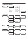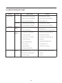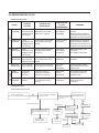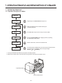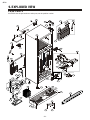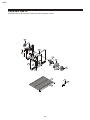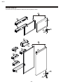
1
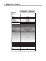
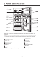
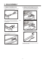
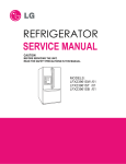
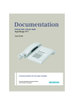
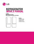
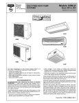
REFRIGERATOR
SERVICE MANUAL
CAUTION
BEFORE SERVICING THE UNIT,
READ THE SAFETY PRECAUTIONS IN THIS MANUAL.
MODELS:
LTC22350ST /01
LTC22350SW /01
CONTENTS
WARNINGS AND SAFETY PRECAUTIONS .................................................................................... 2
1. SPECIFICATIONS ......................................................................................................................... 3
2. PARTS IDENTIFICATION .............................................................................................................. 4
3. DISASSEMBLY...............................................................................................................................5
3-1 Remove Freezer Door............................................................................................................... 5
3-2 Remove Refrigerator Door........................................................................................................ 5
3-3 Replace Refrigerator Door........................................................................................................ 6
3-4 Replace Freezer Door............................................................................................................... 6
3-5 Reverse Freezer Door............................................................................................................... 7
3-6 Reverse and Reattached Refrigerator Door.............................................................................. 8
3-7 Leveling and Door closing......................................................................................................... 11
3-8 Door Alignment......................................................................................................................... 11
3-9 Fan and Fan Motor.................................................................................................................... 12
3-10 Defrost Control Assembly........................................................................................................ 12
3-11 Lamp....................................................................................................................................... 12
3-12 Control Box-Refrigerator......................................................................................................... 12
4. ADJUSTMENT............................................................................................................................... 13
4-1 Comprssor................................................................................................................................ 13
4-2 PCT-Starter .............................................................................................................................. 13
4-3 OLP (Overload Protector)......................................................................................................... 14
4-4 To remove the Cover PTC.........................................................................................................14
5. CIRCUIT DIAGRAM....................................................................................................................... 15
6. TROUBLE SHOOTING................................................................................................................... 16
6-1 Compressor and electric components ..................................................................................... 16
6-2 PTC and OLP ........................................................................................................................... 17
6-3 Other electrical components .................................................................................................... 18
6-4 Service diagnosis chart ............................................................................................................ 19
6-5 Refrigeration cycle ................................................................................................................... 20
7. OPERATION PRINCIPLE AND REPAIR METHOD OF ICEMAKER ............................................ 21
7-1 Operation principle ................................................................................................................... 21
7-2 Ice maker functions .................................................................................................................. 22
7-3 Defect diagnosis function ......................................................................................................... 23
8. DESCRIPTION OF FUNCTION & CIRCUIT OF MICOM............................................................... 24
8-1 Function ................................................................................................................................... 24
8-2 PCB Function ........................................................................................................................... 27
8-3 Resistance Specification of sensor........................................................................................... 30
9. EXPLODED VIEW.......................................................................................................................... 31
SAFETY PRECAUTIONS
Please read the following instructions before servicing your
refrigerator.
7.Before tilting the refrigerator,remove all materials from
On or in the refrigerator.
1.Check the refrigerator for current leakage.
2.To preven telectric shock,unplug before servicing.
8.When servicing the evaporator,wear gloves to prevent
Injuries from the sharp evaporator fins.
3.Always check line voltage and amperage.
4.Use standard electrical components.
9.Service on the refrigerator should be performed by a
Qualified technician.Sealed system repair must be
Performed by a CFC certified technician.
5.Don't touch metal products in the freezer with wet
Hands.This may cause frost bite.
6.Prevent water from spiling on to electric elements or the
Machine parts.
-2-
SPECIFICATIONS
Color
GENERAL FEATURES
Dimensions
MODELS
1. SPECIFICATIONS
LTC22350SW /01
White
Stainless
889 (W) x 856 (D) x 1811 (H) mm
Net Weight
97 Kg
Capacity
22cuft
Refrigerant
R134a
Climate class
Temperate (N)
Rated Rating
115V~ / 60Hz
Cooling System
Fan Cooling
Temperature Control
MICOM control
Full Automatic
Defrosting System
Heater Defrost
Insulation
Compressor
Cyclo, Pentane
MQ53LAUM 115-127V/60 Hz PTC Starting Type
Evaporator
Fin Tube Type
Condenser
Wire Condenser
Lubricanting Oil
Polyol Ester (POE) RL-7H/7 cst 220 ± 10 cc
Drier
MOLECULAR SIEVE XH-7
Capillary Tube
ID Ø0.75
First Defrost
4 Hours
Defrost Cycle
7 - 40 Hours
Desfrosting Device
Heater, Sheath
Anti-freezing Heater
Water Tank Heater
Case Material
REFRIGERATOR
Door Material
Embo (normal)
PCM
Handle Type
Stainless
Pocket Handle
Basket, Quantity
3EA (Normal)
Ice Tray & Bank
In Door Auto Ice maker
Cover, T/V
T/Glass
Lamp
Yes (1) 40W/Blue
Shelf
4 Fix
Tray meat
Yes
Tray Egg
FREEZER
LTC22350ST /01
No
Basket, Quantity
Plastic (2)
Lamp
No
Shelf
Wire
-3-
2. PARTS IDENTIFICATION
A
H
B
C
D
J
E
I
K
F
N
G
M
L
Use this section to become more familiar with the parts and features. Page references are included for your
convenience.
NOTE:This guide covers several different models.The refrigerator you have purchased may have some
or all of the items listed below.The locations of the features shown below may not match your model.
H Freezer Door Bin
A CustomCube Ice maker
B Freezer Shelf
I Dairy Corner
C Digital Sensor Control
J Can Dispenser
D Refrigerator Light
K Door Bin
E Snack Pan
L Refrigerator Door Rack
F Shelves
M Base Grille
G Crisper
Keeps fruits and vegetables fresh and crisp
N Vitabox (Inside)*
*On some models
-4-
3. DISASSEMBLY
3-1 REMOVE FREEZER DOOR
3-2 REMOVE REFRIGERATOR DOOR
• Gently pry o the Top Hinge Cover with a at head
screwdriver and remove (see Fig 1).
• Loosen and remove the 2 bolts and the phillips head
screw to remove the Middle Hinge Bracket from
refrigerator housing (Fig. 4 and 5). Set parts aside.
Fig. 1
Fig. 4
Middle
Hinge Bracket
• Using 10 mm or 13/32-inch socket wrench,
remove
the 3 bolts and lift o the Top Hinge (see Fig. 2).
Set parts aside.
Fig. 5
Fig. 2
• Lift up door slightly and remove it.
Fig. 6
• Lift freezer door slightly and remove it.
(Fig. 3). Set aside.
Fig. 3
To replace doors, begin with refrigerator door and then
follow with freezer door.
-5-
3-3 REPLACE REFRIGERATOR DOOR
• Set door onto Bottom Hinge Pin.
• Place Hinge Pin of Middle Hinge Bracket inside
Hinge Pin Insert on top of door (Fig. 7). Hold door
in place and line up the Middle Hinge Bracket with
the holes in refrigerator housing.
• Place Upper Hinge’s Pin in the top of freezer door
and line up the Upper Hinge with holes in top of
refrigerator. Use the 3 bolts to replace Hinge (Fig. 10).
Fig. 10
Fig. 7
• Carefully force-t Top Hinge Cover back into place
over Hinge (Fig.11).
Fig. 11
• Use the 2 bolts and phillips screw to refasten
the Middle Hinge Bracket and door to the
refrigerator housing. (Fig. 8).
Fig. 8
3-4 REPLACE FREEZER DOOR
• Set the freezer door onto the Middle Hinge Pin
(Fig. 9).
ELECTRICAL SHOCK HAZZARD
Before you begin, either unplug the refrigerator or turn
o power at the circuit breaker or fuse box. Remove
food and any Adjustable Door or Utility Bins from doors.
Failure to do so could result in death or serious injury.
Fig. 9
-6-
3-5 REVERSE FREEZER DOOR
• Gently pry off the Top Hinge Cover with a flat head
screwdriver and remove (see Fig.13).
Fig. 13
• Move the Hinge Pin Insert Bracket to the other side
of the door, keeping the same orientation, and move
the Hinge Pin Insert into the hole on the left side
of the bracket (Fig. 17).
Hinge Pin Insert
Hinge Pin
Insert Bracket
• Using 10mm or 13/32-inch socket wrench, remove
the 3 bolts and lift off the Top Hinge (see Fig. 14).
Set parts aside.
• Reverse Door Closer/Stop by flipping over
(see Fig. 18), place on top of Hinge Pin Insert
Bracket, and tighten both down with the screw.
Fig. 14
Top Hinge
• Lift up door slightly and remove it (Fig. 15).
Fig. 15
Mode Hinge Bracket
• Pry off cover on top of refrigerator on left side to
uncover screw holes (Fig. 19).
• Set freezer door and Top Hinge parts to the side
and remove refrigerator door.
Fig. 19
Hinge Pin
• Turn freezer door upside down on a non-scratch
surface and loosen the screw to remove Door
Closer/Stop and Hinge Pin Insert (see Fig. 16).
Door Closer/ Stop
-7-
Cover
(on top of
refrigerator)
3-6 REVERSE AND REATTACH
REFRIGERATOR DOOR
• Using a ¼-inch socket wrench, loosen and remove
Hinge Pin from the Middle Hinge Pin Bracket.
Remove washer underneath the middle hinge and
set aside
NOTE: At this point the door will be loose, lift up
door slightly and remove it. (Fig. 20 and 20a).
• Remove base grill.
• Remove the washer from the Bottom Hinge Pin (Fig.22).
• Using a ¼-inch socket wrench, loosen and remove
the Hinge Pin from the Bottom Hinge. Reattach
the Hinge Pin to the opposite side of the Hinge
(see Fig. 22 and 22a).
NOTE: This is easier to do while the Hinge is still attached.
Fig. 20
Fig. 22
20
Fig. 20a
Fig. 22a
20a
• Loosen and remove the 2 bolts and the
phillips head screw to remove the Middle
Hinge Bracket from refrigerator housing
(Fig. 21). Set parts aside.
Fig. 21
• Using 10 mm or 13/32-inch socket wrench
with 2-inch extension, loosen the 3 bolts
and remove the Bottom Hinge from right
side of housing (Fig. 23).
Fig. 23
-8-
• At this point, remove the Decorative Bolt on bottom on
refrigerator housing from the left side of refrigerator
(Fig. 24). You will need this hole for the Bottom Hinge.
Fig. 24
• Take out the Hinge Pin Insert and move the Bracket to the
other side of the door,keeping the same orientation (Fig. 28).
• Place Hinge Pin Insert into the left side
of the bracket. Tighten Hinge Pin Bracket
to door (Fig. 28).
Fig. 28
Hinge
Pin Bracket
Hinge Pin Insert
• Move the Bottom Hinge to the left side of housing keeping
the same orientation, and reattach with 3 bolts (Fig. 25).
Now move Decorative Bolt to hole on lower right side
of housing.
Fig. 25
• Take Door Closer/stop and flip (see Fig. 29). Line up screw
holes and mount on left side of door bottom with the two
screws. Turn door upright. It is now ready for re-attaching.
NOTE: The Refrigerator Door Closer/Stop is not used on all
models. The model you have may not include this part.
Fig. 29
• Turn refrigerator door upside down on a non-scratching
surface.
• With door upside down, loosen the 2 screws and remove the
Door Closer/Stop (Fig. 26), then loosen the other two screws to
• With flat-head screwdriver, carefully pry off and remove the
remove the bottom Hinge Pin Insert Bracket with Hinge Pin
cover over the screw holes on the left side of refrigerator
Insert (see Fig. 27).
housing (Fig. 30).
NOTE: The Refrigerator Door Closer/Stop is not used on all
models. The model you have may not include this part.
Fig. 30
Fig. 26
Fig. 27
Door Closer/Stop
• Remove the outer lower Decorative Screw from housing
at area between freezer and refrigerator doors (Fig. 31).
(You will need this hole for the Middle Hinge Bracket).
Hinge
Pin Bracket
Fig. 31
Hinge Pin
Insert
-9-
• Tighten bolts. Force-fit Top Hinge Cover over Top Hinge.
• Following illustration, flip the Middle Hinge Bracket (Flange
will now be on top) and position on left side of refrigerator
and re-attach with two bolts and a Phillips screw. (Fig. 32).
• Place refrigerator door down over pin on bottom hinge.
(Fig. 32).
• Place washer between refrigerator door and middle hinge
and re-attach Hinge Pin to Hinge Bracket with 1/4-in.socket
wrench.
Fig. 36
NOTE: Bracket has been flipped, but Hinge Pin stays in the
same orientation with its hexagonal end facing upward.
• Replace cover from left side of refrigerator top onto the
right of top to cover the holes. Cover is also force-fitted
Cover (on top of
refrigerator)
Fig. 37
• Place Decorative Screw into outer hole on right side
housing.
• Attach cover on the right side. Cover is force-fitted
of
After changing doors, make sure that the corners of the
Door Gaskets are not folded over. To ensure a good seal,
apply a small amount of silicon grease on the corners of
gaskets.
Decorative
Screw
Corners
Fig. 33
REATTACHING FREEZER DOOR
• Put freezer door down over the Hinge Pin on the Middle
Hinge Pin Bracket
• Place Upper Hinge’s Pin in the top of freezer door and line
up the Upper Hinge with holes in top of refrigerator. Use the 3
bolts to replace Hinge.
Fig. 38
Fig. 35
-10 -
3-7 LEVELING AND DOOR CLOSING
3-8 DOOR ALIGNMENT
To avoid vibration, the unit must be leveled. If necessary,
adjust the Leveling Legs to compensate for unevenness
of the floor. The front should be slightly higher than the
rear to aid in door closing.
Your refrigerator has two Front Leveling Screws – one on
the right and one on the left. If your refrigerator seems
unsteady or you want the doors to close more easily,
adjust the refrigerator’s tilt using the instructions below:
1. Plug refrigerator power cord into a 3-prong grounded
outlet. Move the refrigerator into its final position.
2. Remove the base grill.
The two Leveling Screws are located
on the bottom of the refrigerator on either
side (see Fig. 39).
3. Insert a flat screwdriver in slots to adjust the Leveling
Screws (Fig. 39). Turn the leveling screw clockwise
to raise that side of the refrigerator or counterclockwise
to lower it. It may take several turns of the Leveling
Screw to adjust the tilt of the refrigerator.
NOTE: Having someone push against the top of the
refrigerator takes some of the weight off the Leveling
Screws. This makes it easier to adjust the screws.
If the space between your doors is uneven, follow the
instructions below to align the doors:
1. Gently pry off the Top Hinge Cover with a flat head
screwdriver and remove. Loosen the Top Hinge Bolts
using a 10 mm or 13/32-in. socket wrench or
open-end wrench.
2. Have someone hold the freezer door so the space
between the two doors is even, and retighten
the top hinge bolts.
3. Replace the Top Hinge Cover.
Fig. 39
4. Open both doors again and check to make sure
that they close easily. If not, tilt the refrigerator
slightly more to the rear by turning both Leveling
Screws clockwise. It may take several more turns,
and you should turn both Leveling Screws the
same amount.
5. Replace the base grill.
- 11 -
3-9 FAN AND FAN MOTOR
3-11 LAMP
1. Remove the freezer shelf. (If your refrigerator has an
icemaker, unplug and remove the icemaker first).
2. Remove the screw of the cover grille fan
3. Remove the grille by pulling it out and by loosening a screw.
4. Remove the Fan Motor assembly by loosening 4 screws and
disassemble the shroud.
5. Pull out the fan and separate the Fan Motor and Bracket.
Fig. 43
FAN MOTOR
SHROUD
3-11-1 Refrigerator Compartment Lamp
BRACKET
FAN
1. Unplug the power cord from the outlet.
2. Remove refrigerator shelves.
3. Release the hooks on both ends of the lamp shield and
pull the shield downward to remove it.
4. Turn the lamp counterclockwise.
5. Assemble in reverse order of disassembly. Replacement
bulb must be the same specification as the original
(Max. 40 W-1EA).
GRILLE
Fig. 40
3-12 CONTROL BOX-REFRIGERATOR
1. First, remove all shelves in the refrigerator. Then remove
the Refrigerator Control Box by loosening 2 screws.
3-10 DEFROST CONTROL ASSEMBLY
Defrost Control assembly consists of Defrost Sensor and
FUSE–M.
Defrost sensor functions to defrost automatically. It is
attached to metal side of the Evaporator and senses
Temperature. At the temperature of 162°F(72°C), it stops
the emission of heat from the Heater.
Fuse-M is a safety device for preventing over-heating of
the Heater when defrosting.
1. Pull out the grille assembly. (Figure 41)
2. Separate the connector of the Defrost Control
assembly and replace the Defrost Control assembly
after cutting the Tie Wrap. (Figure 42)
GRILLE ASSEMBLY
Fig. 41
DEFROST-CONTROL
ASSEMBLY
CONTROL BOX
COVER LAMP
Fig. 44
2. Remove the Refrigerator Control Box by pulling it
downward.
3. Disconnect the lead wire on the right position and
separate the lamp sockets.
Fig. 42
- 12 -
4. COMPRESSOR ELECTRICAL
4-2-4 Role of Combo TSD
4-1 COMPRESSOR
4-1-1 Role
(1) The combo is attached to the sealed compressor and is used
for the operation and protect the motor.
The compressor intakes low temperature and low pressure gas (2) The compressor is a single phase induction motor. During
from the evaporator of the refrigerator and compresses this gas the starting and operation, the combo allows current flow to both
to high temperature and high pressure gas. It then delivers the the start and main winding.
gas to the condenser.
4-2-5 PTC/Combo - Applied Circuit Diagram
Starting Method for the Motor
The compressor includes overload protection. The PTC starter
and OLP (overload protector) are attached to the outside of the
compressor. Since the compressor is manufactured to
tolerances of 1 micron and is hermetically sealed in a dust and
moisture-free environment, use extreme caution when
repairing it.
COMPRESSOR
ACCESORIES
CAPACITOR PART
PK
OLP
4-1-2 Composition
Cr
4-1-3 Note for Usage
2
RD
Cs
(1) Be careful not to allow over-current.
(2) If compressor is dropped or handled carelessly, poor
operation and noise may result.
(3) Use proper electric components appropriate to the particular
compressor in your product.
(4) Keep compressor dry.
If the compressor gets wet (in the rain or a damp environment)
and rust forms in the pin of the Hermetic Terminal, poor
operation and contact may result. If the hermetic connector
rusts out or fails, refrigerant and oil will be expelled into the
contact area, probably resulting in smoke and fire.
(5) When replacing the compressor, be careful that dust,
humidity, and soldering flux don´t contaminate the inside of the
compressor. Contamination in the cylinder may cause noise,
improper operation or even cause it to lock up.
4
5
3
BL
6
BK
M
GN
/YL
COMP' EARTH
PART
PTC
DIAGRAM
* P.T.C OPTION
EG COMP'
3
2
4-2-1 Composition of PTC- Starter
(1) PTC (Positive Temperature Coefficient) is a no-contact
semiconductor starting device which uses ceramic material
consisting of BaTiO3.
(2) The higher the temperature is, the higher the resistance
value. These features are used as a starting device for the
motor.
(GN)
BL
P.T.C
LD,LQ COMP'
4-2 PTC-STARTER/ COMBO
S
4
5
4
6
3
6
2
5
4-2-2 Role of PTC-Starter
(1) The PTC is attached to the Sealed Compressor and is used
for starting the motor.
(2) The compressor is a single-phase induction motor. During
the starting operation, the PTC allows current flow to both the
start winding and main winding.
COMBO KIT
DIAGRAM
* ALTERNATIVE COMP'
ACCESSORIES
4-2-3 Combo TSD
- 13 -
CR
BL
BK
OLP
TSD (Time Starting Device) is a new electronic starting system
for high efficiency compressors due to the following
characteristics:
(1) Combo concept-overload protector, electronic board and
cover in a single casing.
(2) Fully electronic concept.
(3) Full integration of starting and protection devices.
(4) Free from mechanical and electromagnetic noises.
N
PTC
L
COMBO KIT
(PTC+OLP)
4-2-6 Motor Resarting and PTC/ Combo Cooling 4-3-2 Role of the OLP
(1) It requires approximately 5 minutes for the pressure to
equalize before the compressor can restart.
(2) The PTC/Combo device generates hea during operation.
Therefore, it must be allowed to cool before the compressor can
restart.
(1) The OLP is attached to the sealed compressor used for the
refrigerator. It prevents the motor coil from being started in the
compressor.}
(2) For normal operation of the OLP, do not turn the adjust screw
of the OLP in anyway.
4-2-7 Relation of PTC-Starter / Combo and OLP
(1) If the compressor attempts to restart before the PTC/Combo
device is cooled, the PTC/Combo device will allow current to
flow only to the main winding.
(2) The OLP will open because of the over current condition.
Thissame process will continue (3 to 5 times) when the
compressor attempts to restart until the PTC/Combo device has
cooled. The corret OLP must be properly attached to prevent
damage to the compressor.
Parts may appear physically identical but could have different
electrical ratings. Replace parts by part number and model
number. Using an incorrect part could result in damage to the
product, fire, injury, or possibly death.
(OVERLOAD PROTECTOR cross section)
12345678
330 FBYY
Electrical
characteristics
part number
-S1 BOX98
Customer part
number
Lot code/
date code
Physical
termination
part number
4-2-8 Note for using the PTC-Starter / Combo
(1) Be careful not to allow over-voltage and over-current
(2) Do not drop or handle carelessly.
(3) Keep away from any liquid.
If liquid such as oil or water enters the PTC/Combo,
PTC/Combo materials may fail due to breakdown of their
insulating capabilities.
(4) If the exterior of the PTC/Combo is damaged, the resistance
value may be altered. This can cause damage to the
compressor and result in a no-start or hard-to-start condition.
(5) Always use the PTC/Combo designed for the compressor
and make sure it is properly attached to the compressor. Parts
may appear physically identical but could have different
electrical ratings. Replace parts by part number and model
number. Using an incorrect part could result in damage to the
product, fire, injury, or possibly death.
4-3 OLP (OVERLOAD PROTECTOR)
4-3-1 Definition of OLP
(1) OLP (OVERLOAD PROTECTOR) is attached to the
compressor and protects the motor by opening the circuit to the
motor if the temperature rises activating the bimetal spring in
the OLP.
(2) When high current flows to the compressor motor, the
bimetal wors by heating the heater inside the OLP, and the OLP
protects the motor by cutting off the current flowing to the
compressor motor.
- 14 -
Fig. 45
5. CIRCUIT DIAGRAM
PWB(PCB) ASSEMBLY, DISPLAY
2 1 3 4 5 6
RD BN PK YL BL PR
CON101
RT-SENSOR
A
RD BN
PK YL BL
1 2 3 4 5 6
PR
11 10 9 8 7 6
CON4
CON7
PWB(PCB) ASSEMBLY, MAIN
CON1
YL
BL
BL
SB
BK
BL
BN
BN
SB
BK
N
L
GN/YL
(GN)
CAPACITOR PART
BL
1 RD
V
PWB (PCB) ASSEMBLY, ICE MAKER
OLP
2
RD
Cs
BK
POWER
S/W
CON6
2 BL
1 BK
M
ICE MAKER
MOTOR
CON1
2 BK
1 WH
HEATER,
SHEATH
CON2
1 WH
CON3
1 WH
CON4
2 WH
1 WH
CON5
ICE SENSOR
GN/YL
(GN)
I/MAKER W/VALVE
FUSE-M
(98 C)
PK
Cr
4
5
3
6
BK
S
M
A B
RD
GN
/YL
(GN)
BL
BL
BL
COMP' EARTH
PART
P.T.C
COMP' ACCESSORIES
* ALTERNATIVE COMP'
ACCESSORIES
* P.T.C OPTION
ICE MAKER PART
LD,LQ COMP'
EG COMP'
3
2
GN: GREEN
PK: PINK
BO: BRIGHT ORANGE
PR: PURPLE
CR
BL
*PLUG TYPE,ICE MAKER PART,CAPACITOR PART,
P.T.C,COMP' ACCESSORIES AND COMP' EARTH PART
ON CIRCUIT DIAGRAM ARE SUBJECT TO CHANGE IN
DIFFERENT LOCALITIES AND MODEL TYPE.
BK: BLACK
YL: YELLOW
SB: SKY BLUE
BN: BROWN
FUSE-M
(72 C)
BL
3 4 5 6 7
HEATER
SHEATH
BN
YL
1 2
5
4
6
3
6
2
5
GY: GRAY
WH: WHITE
BL: BLUE
RD: RED
- 15 -
N
4
BK
OLP
SB
BN
CON2
5 4 3 2 1
com
SB
R-SENSOR
com
11 10 9 8 7 6
DEF-SENSOR
BO
BO
WH
WH
nc
CON3
3 2 1
POWER
SUPPLY
CORD
1
2
3
4
5
6
7
8
nc
F-FAN
1
2
3
4
5
6
7
8
9
10
DOOR S/W-R
SB
BN
PR
GY
WH
1 2 3 4
CON6 CON8
R-LAMP
C-FAN
WH WH GY GY
5 4 3 2 1
CON5
B
PTC
L
COMBO KIT
(PTC+OLP)
GN/YL: GREEN/YELLOW
BL/WH: BLUE/WHITE
BK/WH: BLACK/WHITE
RD/WH: RED/WHITE
6. TROUBLESHOOTING
6-1 COMPRESSOR AND ELECTRIC COMPONENTS
1
Power Source.
Remove PTC-Starter/Combo
from compressor and
measure voltage
between Terminal C of
compressor and
terminal 5 or 6 of PTC/Combo
YES
(Rated voltage
2
YES
No voltage.
Replace OLP.
NO
5
Check connection
condition.
Reconnect.
Applied voltage isn't
in acceptable range.
(115V ±10%)
2
Check
Check resistance
resistance
of
of motor
motor
compressor.
compressor.
.
Check the resistance
between M-C, S-C and M-S
in motor compressor.
Check each pin to ground.
3
Check
resistance of
PTC-Starter.
PTC-Starter/Combo
Check resistance of
4
Check OLP.
Check resistance of two
terminals in OLP.
5
Check
starting state.
Check the power supply
under load.
(Compressor attempting
to re-start after being off
for 5 minutes).
Advise customer that
power supply needs to be
checked by an electrician.
5
The resistance between pins should be
between 1 and 50 ohms. The resistance to
ground should be infinite.
Open or short
or short to
ground
Replace
compressor
3
Check resistance of
two terminals in
PTC-Starter/Combo
4
3
5
Refer to Page 17.
Refer to Page 17.
Supply
voltage rating
with ±10%.
YES
Did
compressor
YES
NO
NO
- 16 -
Compressor
is OK
Replace the
compressor
1
6-2 PTC / COMBO AND OLP
Separate PTC-Starter
from Compressor and
measure resistance
between No. 5 and 6
of PTC-Starter with a
Tester.
(Figure 1)
Observation value is
115V/60Hz : 6.8 ? ±20%
The resistance value
is 0 ? (short) or
(open).
Separate OLP from
compressor and check
resistance value between
two terminals of OLP whit a
tester.
(Figure 2)
Shows continuity
Open
Check another
electric component.
Replace OLP.
5
6
Normal operation of
compressor is impossible
or poor.
?
Figure 1
- 17 -
Figure 2
Replace PTCStarter.
6-3 OTHER ELECTRIC COMPONENTS
• Not cooling at all
Compressor
doesn't run.
Check for open short or
incorrect resistance readings
in the following components
Cause
a. Starting devices
Short, open or broken.
b. OLP
Poor contact
or shorted.
c. Compressor coil
Coil open or shorted.
d.Wiring harness
Poor contact
or shorted.
Replace
indicated component.
• Poor cooling performance
Compressor runs
poorly.
Fan motor
doesn't run.
Check a starting
voltage.
Low voltage.
Raise voltage.
Check voltage at
starting devices.
Poor or broken or
open contact.
Replace
indicated component.
Check current at
Compressor.
Shorted.
Check rating of OLP.
Lack of capacity.
Check wiring circuit.
Wire is open or
shorted.
Replace
indicated component.
Coil is shorted or
open.
Check Fan Motor.
Heavy frost buildup on
EVAPORATOR.
Check current flow in
the following
components:
- Sensor
- Fuse-M
Check current flow in
the Defrost Heater.
- 18 -
Open.
Replace
indicated component.
Open.
Replace
Defrost Heater.
6-4 SERVICE DIAGNOSIS CHART
COMPLAINT
Electronic Display not
operating correctly
SYMPTOM
Not cold enough
SOLUTION
1. No Display at all
2. Partial or
abnormal display
Not cooling
POSSIBLE CAUSES
1. Display on but
compressor not
operating
1. Display on
compressor is
operating
1. Supply voltage not within specifications
1. Check supply voltage to refrigerator
2. Open in wiring harness from PWB board
2. Chack wiring and connectors to PWB board
3. Open in door monitor switch circuit
3. Check door monitor circuit
1. Supply voltage not within specifications
1. Check supply voltage to refrigerator
2. Open wiring harness from PWB board
2. Chack wiring and connectors to PWB board
1. Compressor not operating
1. Check for compressor operation by using the test key
on main circuit board.
2. Open in compressor circuit
2. Check for open on OLP, PTC, compressor, wiring, etc.
1. Condenser fan motor not operating
1. Check condenser fan motor and wiring circuit
2. Condenser coils blocked
2. Check air flow across condenser
3. Evaporator fan motor not operating
3. Check evaporator fan motor and wiring circuit
4. Internal air flow blocked
4. Check air ducts
5. Sensor not operating properly
5. Check refrigerator and freezer sensors
6. Door not sealing
6. Check for proper door seal
7. Evaporator frosted up
7. Check defrost circuit components
8. Sealed system related problem
Not defrosting
1. Freezer has to
much frost
1. Open in defrost circuit
1. Check defrost heater and circuit using Test Key
2. Defrost sensor not operating correctly
2. Check sensor
3. Defrost drain clogged
3. Check drain
- 19 -
6-5 REFRIGERATING CYCLE
• Troubleshooting Chart
CAUSE
PARTIAL
LEAKAGE
STATE OF
THE UNIT
STATE OF THE
EVAPORATOR
LEAKAGE
Freezer
compartment and
Refrigerator don't
cool normally.
Low flowing sound of
Refrigerant is heard and
frost forms in inlet only.
COMPLETE Freezer
LEAKAGE
compartment and
Refrigerator don't
cool normally.
RESTRICTEDBYDUST
PARTIAL
RESTRICTION
WHOLE
RESTRICTION
Freezer
compartment and
Refrigerator don't
cool normally.
Flowing sound of refrigerant
is not heard and frost isn't
formed.
Flowing sound of refrigerant
is heard and frost forms
in inlet only.
Freezer
Flowing sound of refrigerant
compartment and
is not heard and frost isn't
Refrigerator don't cool. formed.
MOISTURE
Cooling operation
RESTRICTION stops periodically.
TEMPERATURE
OF THE
COMPRESSOR
REMARKS
A little higher
than ambient
temperature.
• Refrigerant level is low due
to a leak.
• Normal cooling is possible by
restoring the normal amount of
• Refrigerant and repairing the leak.
Equal to ambient
temperature.
• No discharging of Refrigerant.
• Normal cooling is possible by
restoring the normal amount of
refrigerant and repairing the leak.
A little higher
than ambient
temperature.
• Normal discharging of the
refrigerant.
• The capillary tube is faulty.
Equal to ambient
temperature.
• Normal discharging of the
refrigerant.
Flowing sound of refrigerant
is not heard and frost melts.
Lower than
ambient
temperature.
• Cooling operation restarts
when heating the inlet of the
capillary tube.
DEFECTIVE
COMPRESSION
COMPRESSION
Freezer and
Refrigerator
don't cool.
Low flowing sound of
refrigerant is heard and
frost forms in inlet only.
A little higher
ambient
temperature.
• Low pressure at high side
of compressor due to low
refrigerant level.
NO COMPRESSION
No compressing
operation.
Flowing sound of refrigerant
is not heard and there is
no frost.
Equal to ambient
temperature.
• No pressure in the high
pressure part of the
compressor.
Leakage Detection
Check sealed system for leak.
Check if compressor runs.
(If don’t , wait a while until it start to work)
YES
Check frost pattern on Evaporator.
(Eva In, Eva Out)
No frost or frost forms
in inlet only
Check for oil leak on high
side (Machinery Room)
YES
If frost is formed normally
Normal Amount
Only check that there is not any
hole or bad welding in Eva in-Eva
out.
Faulty
Compressor
Gas leakage
Confirm refrigerant
amount
None or too much.
Recharge refrigerant
(check correct quantity)
Moisture restriction.
intermittent problem.
Replace
Compressor
No frost
normally
Repair it.
Frost formed
normally
Finished OK
Restriction
- 20 -
Frost formed
normally
7. OPERATION PRINCIPLE AND REPAIR METHOD OF ICEMAKER
7-1 OPERATION PRINCIPLE
7-1-1 Operation Principle of Ice Maker
Power On
Start Position
Icemaking
Mode
Harvest
Mode
Fill
Park Position
Test Mode
• Adjusts Ejector to Start Position with power on.
• Waits until water becomes cold after starting the
Icemaking operation.
• Runs MOTOR to drop ice from the tray into the ICE BIN.
• Performs Icemaking Mode after supplying water by operating
the SOLENOID in ICE VALVE.
• With the detect lever, checks if the ICE BIN is full.
• To operate LINE and SERVICE, press and hold the Cube Size button
for 3 seconds. The icemaking will run through 3 stages:
Harvest
Fill
Icemaking.
1. Turning the Icemaker stop switch off (O) stops the icemaking function.
2. Setting the Icemaker switch to OFF and then turning it back on will reset the icemaker control.
Cube Size button
Power (On/Off) Switch
- 21 -
7-2 ICE MAKER FUNCTIONS
7-2-1 Ice Making Mode
1. Icemaking refers to the freezing of supplied water in the ice trays. Complete freezing is assured by measuring the
temperature of the Tray with icemaking SENSOR.
2. Icemaking starts after completion of the water fill operation.
3. The icemaking function is completed when the sensor reaches -7°C, 60 to 240 minutes after starting.
NOTE : After icemaker power is ON, the icemaker heater will be on for test for 9 sec.
7-2-2 Harvest Mode
1. Harvest (Ice removing) refers to the operation of dropping ices into the ice bin from the tray when icemaking has
completed.
2. Harvest mode:
(1) The Heater is ON for 30 seconds, then the motor starts.
(2) Harvest mode is completed if it reaches start position again while Heater & Motor are on at the same time.
A. ice bin is full : The EJECTOR stops (heater off).
B. ice bin is not full : The EJECTOR rotates twice to open for ice.
NOTE : If the EJECTOR does not rotate once within 5 minutes in status (2), separate heater control mode starts
operating to prevent the EJECTOR from being constrained. (It is recommended that the user open for ice to
return to normal mode.)
7-2-3 Fill/Park Position
1. Once a normal harvest mode has been completed, the water solenoid will be activated.
2. The amount of water is adjusted by pressing the fill key repeatedly. This changes the time allowed for fill as illustrated in
the table below.
Water supply amount table
STAGE
TIME TO SUPPLY
1
6 sec.
INDICATIONS
REMARKS
The water amount will vary depending
2
on the water control switch setting, as
7 sec.
well as the water pressure of the
connected water line.
3
8 sec.
- 22 -
7-2-5 Function TEST
1. This is a compulsory operation for test, service, cleaning, etc. It is operated by pressing and holding the Cube Size button
for 3 seconds.
2. The test works only in the Icemaking Mode. It cannot be entered from the Harvest or Fill mode. (If there is an ERROR, it
can only be checked in the TEST mode.)
3. Caution! If the test is performed before water in the icemaker is frozen, the ejector will pass through the water. When the fill
mode begins (Stage 4), unless the water supply has been shut off, added water will overflow into the ice bin. If the control
Doesn’t operate normally in the TEST mode, check and repair as needed.
4. After water is supplied, the normal CYCLE is followed: icemaking
Harvest
Fill
Park Position.
5. Five seconds after Stage 5 is completed, the icemaker returns to MICOM control. The time needed to supply water
resets to the pre- test setting.
Diagnosis TABLE
STAGE
ITEMS
1
HEATER
2
MOTOR
3
HALL IC
INDICATOR
REMARKS
*
Five seconds after heater starts, heater will
go off if temperature recorded by sensor is
10°C (50°F)or lever is in up position.
Five seconds after heater starts, you can
confirm that motor is moving.
You can confirm Hall IC detection of position.
(TRAY)
4
SOLENOID VALVE
5
HALL IC
(LEVER)
6
Reset
Two seconds after detection of initial
position, you can confirm that valve is on.
You can check when the Hall IC is sensing a full
ice condition. (If there is a water fill error, the
fifth LED is not on.)
Five seconds after fifth stage is completed,
the icemaker resets to initial status.
Return to Status prior to
TEST MODE
7-3 DEFECT DIAGNOSIS FUNCTION
7-3-1 ERROR CODES shown on Ice Maker water supply control panel
NO
DIVISION
1
Normal
2
Icemaking
Sensor
malfunction
3
Icemaker Kit
malfunction
PROBLEM
INDICATOR
Note fill times
(see previous page)
None
Open or shorted wire or sensor
Ejector blades have not reached
the park position after 18
minutes from start of harvest
mode
- 23 -
REMARKS
Display switch
operates properly
Make sure that the wire
on each sensor is
connected.
Check
HALL IC/MOTOR/
HEATER/RELAY
8. DESCRIPTION OF FUNCTION & CIRCUIT OF MICOM
8-1 FUNCTION
8-1-1 Function
1. When the appliance is plugged in, is set to “3” for the refrigerator. You can adjust the Refrigerator control temperature by
pressing the ADJUST button.
2. When the power is initially applied or restored after a power failure, it is automatically reset to “3”.
1
2
3
4
WARMER
5
COLDER
TEMPERATURE
ADJUST
8-1-2 Defrost Cycle
Defrosting starts each time the accumulated COMPRESSOR running time is between 7 and 50 hours. This time is
determinate by how long the doors are opened.
For initial power on or for restoring power, defrosting starts when the compressor running time reaches 4 hours.
Defrosting stops if the sensor temperature reaches 50 °F (10 °C) or more. If the sensor doesn’t reach the 50 °F (10°C) in 1
hour, the defrost mode is malfunctioning. (Refer to the defect diagnosis function).
Defrosting won’t function if the sensor if defective (wires are cut or short circuited)
8-1-3 Electrical Parts Operation in Sequence.
Electrical parts such as COMP, defrost heater, freezer FAN, etc. Operate in the following order to prevent noise and parts
damage. Several parts are started at the same time at initial power on and are turned off together when TEST is completed.
OPERATING
ORDER
INITIAL POWER ON
Temperature of defrost
sensor is 113°F (45°C)
or more .
POWER
ON
0.5
Se
c
Temperature of defrost
sensor is lower than
113°F (45°C
(45°C).
POWER
ON
0.5
Sec
0.5 Sec
DefHeater
ON
REMARKS
COMP,
F-FAN
ON
10 Sec
COMP,
F-FAN
ON
- 24 -
DefHeater
OFF
8-1-4 Defect Diagnosis Function
1. If there is a problem, an error code will appear..
2. The buttons will not operate.
3. When the problem is repaired, the display will return to normal.
4. The error code is displayed using the LEDs.
1
2
3
WARMER
4
5
COLDER
TEMPERATURE
ADJUST
• ERROR CODE on Refrigerator Temperature panel
NO
Item
:ON
Error Code
R2 R3 R4 R5
Error Description
1
Ref. Sensor
Ref. Sensor Open or Short
2
Heater Sensor
Defrost Sensor Open or Short
3
RT Sensor
:OFF
Remarks
* Check each sensor
Ambient Sensor Open or
Short
4
Defrost time last more
than one hour and the
defrost sensor never reach
Defrosting
Problem
10°C or 50°F
5
F-FAN LOCK
F-FAN LOCKED
- 25 -
Check FUSE-M,
DEF-SENSOR,
Drain, Heater Drive
Relay
Check if something is
locking the F-FAN
8-1-5 TEST MODE
1. Test mode allows checking the PCB and the function of the product as well as determining the Defective part in case of an
error.
2. The test button is on the main PCB of the refrigerator (Test S/W).
3 While in the test mode, the ADJUST button will not operate.
4. After exiting the test mode, be sure to reset by unplugging and plugging in the appliance,
5. If an error, such as a sensor failure is detected while in the test mode, the test mode is cleared and the error code is
displayed.
6. While an error code is displayed, the test mode will not be activated.
MODE
Key Control
Push the test
button once
TEST 1
Push the test
button once while
in TEST MODE 1
TEST
Operation
1) Continuous operation of the
COMP, Freezer FAN
and Cooling FAN.
2) DEFROSTING HEATER OFF
3) ALL DISPLAY ON
4) LAMP RELAY ON/OFF
OPERATED BY DOOR SWITCH
1) COMP OFF
2) Freezer FAN and Cooling
FAN OFF
3) Defrosting Heater ON
4) 1, 3, 5 LED ON
Remarks
*The maximum
time for TEST 1
is 5 min.
Ref.
Temp.
:ON
Display
:OFF
Operate max 1 Hr
RESET
Push the test button
Once while in TEST
MODE 2
Reset to the default settings
(Compressor will delay 7
minutes for Power ON)
* Demonstration MODE
1. To enter this mode open refrigerator and freezer door; press both door switches (display will turn off) at the same time press
Temp. Adjust button for 5 seconds.
2. The LED panel will blink sequentially (1-2-3-4-5) to indicate that the compressor, fans and defrost heaters are not operating.
3. The Lamp work normally.
4. To reset to Normal Operating Mode repeat step 1.
5. If a Power Failure occur and the OFF MODE was active, it going to start in OFF MODE.
6. When the off mode is disable the display show the notch 3 (restart).
- 26 -
8-2 PCB FUNCTION
Con 2
Con 3
Con 1
Con 8
Con 2
Con 5
Con 6
- 27 -
Con 7
8-2-1 Power Circuit
Power is supplied to the control board at the pin 11 and 9 of connector #1. (Refer to figure 1)
CON1
BL
BN
SB
BK
BN
N
L
GN/YL
(GN)
CAPACITOR PART
V
OLP
2
RD
Cs
BK
BL
1 RD
POWER
S/W
CON6
2 BL
1 BK
M
ICE MAKER
MOTOR
CON1
2 BK
1 WH
HEATER,
SHEATH
CON2
1 WH
CON3
1 WH
CON4
2 WH
1 WH
CON5
ICE SENSOR
GN/YL
(GN)
I/MAKER W/VALVE
FUSE-M
(98 C)
PK
Cr
4
5
3
6
BK
S
M
FUSE-M
(72 C)
BL
SB
BK
A B
RD
HEATER
SHEATH
YL
BL
com
BL
com
BN
YL
3 4 5 6 7
nc
SB
POWER
SUPPLY
CORD
BN
1 2
nc
SB
CON2
5 4 3 2 1
DOOR S/W-R
11 10 9 8 7 6
R-LAMP
CON3
3 2 1
GN
/YL
(GN)
BL
BL
BL
COMP' EARTH
PART
P.T.C
COMP' ACCESSORIES
PWB (PCB) ASSEMBLY, ICE MAKER
ICE MAKER PART
FIGURE 1
8-2-2 Load and Door Light Circuit (HV)
1. Load Drive Condition Check
To measure outputs of the control board, check voltages between the pins for the following components:
(Refer to figure 1)
Circuit
Compressor
Defrost
Heater
R LAMP
Ice Maker
Pin
Number
Con 1 Pin 1
Pin
Number
Con 1 Pin 3
Output
Voltage
115 VAC
PIN
Con 2 Pin 7
Con 2 Pin 3
Con 1 Pin 7
Con 1 Pin 3
Con 1 Pin 3
Con 1 Pin 5
115 VAC
115 VAC
115 VAC
PIN
11
N
9
L1
1
N/C
CONNECTOR 1
7
5
L(I/M)
N(I/M)
CONNECTOR 2
3
DOOR LAMP
3
N
1
COMP
5
N/C
7
DEF-HTR
NOTE: When the door of the refrigerator is left open for 7 minutes or longer, the lamp of the refrigerator turns off automatically.
- 28 -
2. Door Monitor Circuit (LV)
Measurement between
pins 4 and 3 Con 8
0 volts
5 volts
Refrigerator
Door Close
Door Open
CONNECTOR 8
PIN
1
2
3
4
R-DOOR S/W
RT-SNR
8-2-3 Temperature Sensor Circuit (Refer to figure 2)
Voltage supplied to each sensor wil range between 0.5 volts -22°F(-30°C) and 4.5 volts 122°F(50°C) depending upon the
temperature in the compartments. A measurement of 0 volts indicates a short in the sensor circuit. A measurement of 5
volts indicates an open in the sensor circuit.
PWB(PCB) ASSEMBLY, DISPLAY
2 1 3 4 5 6
RD BN PK YL BL PR
CON101
RT-SENSOR
A
RD BN
PK YL BL
1 2 3 4 5 6
PR
11 10 9 8 7 6
C-FAN
SB
BN
PR
GY
WH
F-FAN
PIN
1
N/C
2
N/C
3
1
2
3
4
5
6
7
8
9
10
WH WH GY GY
5 4 3 2 1
CON5
B
1 2 3 4
CON6 CON8
CON4
CON7
PWB(PCB) ASSEMBLY, MAIN
1
2
3
4
5
6
7
8
DEF-SENSOR
BO
BO
WH
WH
R-SENSOR
FIGURE 2
CONNECTOR 7
4
5
6
D-SNR
R-SNR
7
N/C
8
N/C
PIN
1
CONNECTOR 8
2
3
4
RT-SNR
R-DOOR S/W
To measure the outputs of the sensors, check the voltages between the pins as in the table. And refer the values in the
section “RESISTANCE SPECIFICATION OF SENSOR”
SENSOR Pin Number Pin Number
D-SNR
Con 7 Pin 3
Con 7 Pin 4
R-SNR
Con 7 Pin 5
Con 7 Pin 6
RT-SNR
Con 8 Pin 1
Con 8 Pin 2
To measure the outputs of the fans on the control boards check the voltages between the pins for the following components:
FAN
Freezer Fan
Cooling Fan
PIN
1
N/C
2
C-FAN
G
PIN NUMBER PIN NUMBER
Con 4 pin 5
Con 4 pin 2
3
V
Con 4 pin 6
Con 4 pin 3
OUTPUT VOLTAGE
MOTOR ON MOTOR OFF
10 - 14 VCD 2 VCD or less
10 - 14 VCD 2 VCD or less
CONNECTOR 4
4
5
6
F-FAN
F
G
V
- 29 -
7
8
9
10
N/C
N/C
N/C
N/C
N/C
8-3 RESISTANCE SPECIFICATION OF SENSOR
•
TEMPERATURE DETECTED
SENSOR
RESISTANCE OF REFRIGERATOR
DEFROST SENSOR
VOLTAGE
-20°C
77 K?
3.73
-15°C
60 K?
3.49
-10°C
47.3 K?
3.22
-5°C
38.4 K?
2.95
0°C
30 K?
2.67
+5°C
24.1 K?
2.4
+10°C
19.5 K?
2.14
+15°C
15.9 K?
1.89
+20°C
13 K?
1.66
+25°C
11 K?
1.46
+30°C
8.9 K?
1.27
+40°C
6.2 K?
0.96
+50°c
4.3 K?
0.72
• The resistance of the SENSOR has a ±5% common difference.
•Temperature of the SENSOR must be stabilized for minimum of 3 minutes before accurate measurement can be
taken.
• Measure the F-SENSOR, SUPER FROST SENSOR, R1, R2-SENSOR after disconnect CON5 of PWB AS
SY, MAIN.
- 30 -
#EV#
9. EXPLODED VIEW
CASE PARTS
CAUTION: Use the part number to order part, not the position number
103B
B01
281B
S01
401A
301A
281A
103A
501F
282E
418A
411A
501A
282B
406B
120A
145A
304A
282H
S01
619B
S14
120B
903D
503C
503D
S16
125D
105A
282C
409B
145B
318A
317A
158A
419B
125D
327A
314A
S01
106A
410G
310A
283B
B03
308A
307B
309A
323B
305B
106A
328A
305C
307A
412D
312A
315A
329C
103C
420A
405B
319C
319A
405B
105F
305C
305B
S01
-31-
S01
#EV#
FREEZER PARTS
CAUTION: Use the part number to order part, not the position number
.
405F
330B
332A
110D
S01
405C
319E
284A
S22
404A
329A
284C
149F
404Z
149A
-32-
#EV#
REFRIGERATOR PARTS
CAUTION: Use the part number to order part, not the position number
.
143E
140D
S24
140B
140E
143F
142D
S24
140B
S24
142E
128A
S24
170A
128B
143E
140D
S24
140B
140E
143E
140D
S24
S24
140B
140E
S24
103E
167B
154A
103E
151A
155B
151A
-33-
151C
#EV#
DOOR PARTS
CAUTION: Use the part number to order part, not the position number
200A
201A
205D
203A
212G
205D
286A
210B
210A
241A
230A
233A
231A
241B
241C
281E
241E
241C
241C
286A
241D
243A
283F
-34-
#EV#
ICEMAKER PARTS
CAUTION: Use the part number to order part, not the position number
622B
618A
616E
S29
623C
600C
S28
602A
619C
619A
262D
600A
S31
131A
-35-
MFL62526015
December, 2009
Rev. 01