1
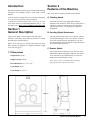
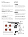
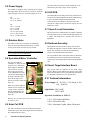
Series Operator’s Manual 6212 Material Avenue Loves Park, Illinois 61111 815-654-0212 or 800-435-8319 The Originator of Electronic Darts www.arachnidinc.com P/N 42383 Rev. F Arachnid Limited Warranty for Chuck A Luck Darts Arachnid, Inc., thoroughly inspects and tests all products before they leave the facility and is therefore not responsible for any damages occurred during shipping. Report any damage, whether hidden or obvious, to the shipping company immediately and resolve it through them. 1. Definitions: As used herein, the term “Buyer” shall mean the purchaser of the goods, the term “Goods” shall mean all Chuck A Luck Darts game products, equipment, accessories and any labor and services ordered by Buyer from Arachnid. 2. Warranty: During the warranty period, which is ninety (90) days for the complete game product and one (1) year for the darthead assembly consisting of the spider, segments, matrix and darthead arm, Arachnid will repair or replace at its plant in Loves Park, Illinois, any part of the Goods, which part has been manufactured by Arachnid, and which Arachnid determines to have failed because of defective design, material or workmanship under normal use and service. Arachnid shall have no warranty or other liability for any part not manufactured by it, but agrees to cooperate with Buyer in obtaining an assignment of Arachnid’s warranty rights against the manufacturer. Prior to repair or replacement, Arachnid shall have the right to examine the part at its option either at Buyer's location or at Arachnid’s plant in Loves Park, Illinois. For this warranty to apply, Buyer must give Arachnid written notice of any warranted defect within fifteen (15) days after discovery and, in any event, not later than the date on which this warranty expires, or Buyer will be barred from any remedy. Upon Arachnid’s written authorization, the Goods must be shipped to Arachnid freight prepaid within a reasonable time thereafter. This warranty shall not apply to any of the Goods or parts thereof repaired or altered by anyone but Arachnid, operated or installed contrary to instructions, subjected to misuse, negligence, vandalism, accident, fire or water damage and improper or faulty electrical power source. This warranty is not assignable and expires upon the earlier of Buyer's transfer, sale or other disposition of the Goods, or one (1) year from the date of shipment of the Goods by Arachnid to Buyer. Arachnid’s liability under this warranty shall be limited to repairing or replacing warranted Goods or, if such Goods cannot be repaired or replaced by Arachnid, to the return of the purchase price paid for the defective or nonconforming warranted Goods; provided, that Buyer shall first return to Arachnid those goods for which a refund of the purchase price is to be made. THE WARRANTIES PRINTED ABOVE ARE THE ONLY WARRANTIES APPLICABLE TO THE GOODS. ALL OTHER WARRANTIES, EXPRESSED OR IMPLIED, INCLUDING BUT NOT LIMITED TO THE IMPLIED WARRANTIES OF MERCHANTABILITY AND FITNESS FOR A PARTICULAR PURPOSE, ARE DISCLAIMED. 4. Limitation of Liability ARACHNID SHALL NOT BE LIABLE, WHETHER IN CONTRACT, IN TORT, UNDER ANY WARRANTY, IN NEGLIGENCE, OR OTHERWISE, FOR INCIDENTAL, CONSEQUENTIAL OR SPECIAL DAMAGES OR FOR COSTS OF REMOVAL OR SHIPMENT. UNDER NO CIRCUMSTANCES SHALL ARACHNID'S LIABILITY OR BUYER'S REMEDY FOR DAMAGES AGAINST ARACHNID EXCEED THE AMOUNT OF THE PURCHASE PRICE OF GOODS SOLD FOR WHICH OR RELATING TO WHICH CLAIM IS MADE. IN THE EVENT THAT ARACHNID'S WARRANTY, IF ANY, OR ANY OTHER OBLIGATION OF ARACHNID APPLICABLE TO THE GOODS FAILS OF ITS ESSENTIAL PURPOSE, BUYER'S EXCLUSIVE REMEDY SHALL BE LIMITED TO RETURN OF OR CREDIT FOR SO MUCH OF THE PURCHASE PRICE AS IS APPLICABLE TO THE GOODS WHICH ARE NONCONFORMING OR DEFECTIVE, PROVIDED SUCH GOODS ARE RETURNED TO ARACHNID. THE PRICE STATED FOR THE GOODS, AS SHOWN IN THE ORIGINAL INVOICE, IS BASED UPON AND IN CONSIDERATION FOR LIMITING ARACHNID'S LIABILITY. NO ACTION ARISING OUT OF THE GOODS MAY BE BROUGHT BY BUYER MORE THAN FIFTEEN (15) MONTHS AFTER THE DATE OF SHIPMENT OF THE GOODS BY ARACHNID TO BUYER. BUYER'S REMEDIES AS PROVIDED HEREIN ARE ITS SOLE AND EXCLUSIVE REMEDIES. Table of Contents Introduction 1 Section 1: General Description 1.1 Dimensions 1 1 Section 2: Features of the Machine 1 Section 3: Chuck A Luck Basics 2 Section 4: Operation 4.1 Power Up 4.2 Game Play 4.3 Removing the Darts 4.4 Disabling the Bullseye 4.5 How the Chuck A Luck Works 2 2 2 3 3 3 Section 5: Technical Description 5.1 Digital Display 5.2 Power Supply 5.3 Rotation Motor 5.4 Specialized Motor Controller 5.5 Solar Cell PCB 5.6 LED PCB 5.7 Chuck A Luck Illumination 5.8 Dart Head Assembly 5.9 Smart Target Interface Board 5.10 Technical Information 3 3 4 4 4 4 4 4 4 4 4 Section 6: Maintenance 6.1 Cleaning the Dartheads 6.2 Testing the Target Interface Board 6.3 Replacing the Motor Belt 6.4 Replacing the Motor 6.5 Segment Test 6.6 Viewing the Reset Counter 5 5 6 6 6 7 7 Section 7: Parts Listing 8 Section 8: Troubleshooting Display PCB Schematic Target Interface PCB Schematic LED PCB Schematic Solar Cell PCB Schematic 12 13 14 15 16 Chuck-A-Luck Operating Manual i The most current version of this manual is always available on the Arachnid website at: http://www.arachnidinc.com Note: This equipment has been tested and found to comply with the limits for a Class A digital device, pursuant to part 15 of the FCC Rules. These limits are designed to provide reasonable protection against harmful interference when the equipment is operated in a commercial environment. This equipment generates, uses, and can radiate radio frequency energy and, if not installed and used in accordance with the instruction manual, may cause harmful interference to radio communications. Operation of this equipment in a residential area is likely to cause harmful interference in which case the user will be required to correct the interference at his own expense. Covered by one or more of the following U.S. and/or foreign patents. 140531, 5020806, 5197094, 5359510, 5401033, 5496039, 0477320, P69120886.7, 5114155, 5318319, D328726, 5355302, 5848398, 6397189, 6279912, D414521, D423597, D448809, D468368, 214662, 2815483, ZL01302307.1, 40103986.2, 151194, 6076021, 5743533, 5681044, 5482291, 4955967, 4881744, 6805354, Warning: Keep Safety in mind, make sure all darts are thrown at the Chuck A Luck targets and not bystanders. Suitable for indoor use only. ii Chuck A Luck Operating Manual Introduction This manual contains operation, parts lists and troubleshooting information for Arachnid’s Chuck A Luck Darts carnival machine. If you encounter a problem that is not covered in this manual, or if you have any questions, contact Arachnid at 1-800-435-8319 (815-654-0212) from 8 a.m. to 5 p.m. CST. You can also reach us at [email protected] or visit our support site at http://www.arachnidinc.com/support.php Section 1 General Description Chuck A Luck Darts is a carnival game with four targets attached to metal arms. These arms are attached to a central axis that rotates counterclockwise. Players try to win prizes by scoring points using only three darts. The total is displayed on a digital scoreboard. A high score wins a big prize! 1.1 Dimensions Weight Boxed: 300 lbs Weight Unboxed: 280 lbs Boxed Dimensions: 70” x 35” x 68” Section 2 Features of the Machine This section lists the features available on the machine. A. Rotating Heads The Chuck A Luck has four target heads which are attached to four metal arms. These arms are connected to a central axis which is controlled by the operator. Each target has the numbers 1-20 displayed on a bright red background. B. Scrolling Digital Scoreboard The LED read out keeps track of every dart hit. It allows the accurate tracking of scores so the operator can spend more time with the customer. The display is reset each time the dartheads start their rotation or when the Remote Score Reset Button is pressed. C. Remote Switch This remote allows the operator to clear the score on the LED display without stopping the dartheads. This allows more customers to play without having to wait for the dartheads to reach maximum velocity. Note: There is a five second delay after starting or stopping the motor with the reset switch. Game Height: 89.85” Game Width: 69” X 41.5” Chuck-A-Luck Operating Manual 1 Section 3 Chuck A Luck Basics Section 4 Operation LED Score Board - Automatically keeps track of the customer’s score on large (2.24”) LED’s. 4.1 Power Up Drape - Displays the Chuck A Luck graphic and catches missed darts. The darts slide down the drape and are deposited at the bottom for easy pick up. Drape Support - Holds the drape, LED Scoreboard and Lights. Dartheads - Customers throw the darts at these targets. Each one has its own matrix which senses dart hits. Numbered Ring - Displays the darthead segment numbers so that players have an idea of the points they are aiming for. Darthead Hub - Contains the Smart Target Interface Board that all the dartheads are connected. Motor Case - Contains the motor that rotates the dartheads. It also contains the power supply that powers the lamps and scoreboard. The tethered Remote Score Reset Button comes out the back of the Motor Case. After the power cord is plugged into a power source, the Chuck A Luck will run through a segment test displaying 888 on the scoreboard. Once the segment test is finished, the Chuck A Luck will display it’s current software version. The scoreboard will then begin a countdown starting at 200. During this time, the capacitor is charging and a communications link with the computer boards is established. The Chuck A Luck is ready for play once the scoreboard shows 0. 4.2 Game Play Start the dartheads rotating by gently spinning the darthead hub counterclockwise. The motor will start within a quarter of a turn. Caution: Take care not to allow the rotating pieces to touch the drape. Static electricity can build up when this happens. Base - This plastic base supports the Chuck A Luck. Casters - Allows for mobility so that the Chuck A Luck can be placed in any position. The front two casters lock so the Chuck A Luck will not roll once setup. After starting the darthead rotation, allow 3 seconds for the dartheads to reach maximum speed. This allows the Chuck A Luck to finish its setup preparations and diagnostics. LED Scoreboard Drape Drape Support Darthead Numbered Ring Darthead Hub Motor Case Base Caster 2 Chuck A Luck Operating Manual Players throw darts at the rotating dartheads trying to score enough points to win a prize. The LED Scoreboard keeps track of the points. Typically the higher the points the better the prize. Below is a suggestion that has proved successful when the player is allowed three darts. Win a Huge Prize (TV Set, Giant Stuffed Animal, DVD Player) Win a Large Prize 101 Points (Medium Stuffed Animal, Poster, CD) Win a Small Prize 71 Points (Small Stuffed Animal, Plastic Ring, Fake Teeth) 151 Points Suggested Prizes Stop the darthead rotation by holding the dartheads still for two seconds. Stopping and restarting the dartheads will clear the score from the scoreboard. The Remote Score Reset Button allows you to clear the score without stopping the dartheads. 4.3 Removing the Darts 4.5 How the Chuck A Luck Works The following is a brief description on how the Chuck A Luck keeps score. These instructions, plus the flow chart below, should help you understand the process involved. When a dart strikes one of the dartheads, it triggers one of the sensors on the switch matrix. The switch matrix then sends a signal to the Smart Target Interface Board in the darthead hub. The Smart Target Interface Board sends a signal to the solar cell PCB in the motor enclosure. This board then sends an infrared signal to the LED board in the motor enclosure. The LED board sends the signal to the scoreboard which displays the points. The scoreboard sends a confirmation signal back to the LED board. Scoreboard To remove the darts from the dartheads easily, grasp the dart shaft firmly and twist clockwise while pulling it toward you. 4.4 Disabling the Bullseye By default the bullseye is on. The bullseye is the center two segments. When enabled it will score 50 points. To disable the bullseye, you will need to change a jumper setting in the scoreboard. 1. 2. 3. Open the back of the digital scoreboard. Locate the jumper at JP1. Pull the plunger up to enable the bullseye. Push the plunger down to disable the bullseye. Section 5 Technical Description Below are technical descriptions of the many parts within the Chuck A Luck. 5.1 Scrolling Digital Display Board The digital display board converts input from the Smart Target Interface Board and displays it on three, seven segment LED displays. The display can count up to 99,999. The digital display also receives input from the motor reset switch. This clears the score from the display. Bull Enabled Bull Disabled Chuck-A-Luck Operating Manual 3 5.2 Power Supply The solar cells also reflect the infrared light back to the LED PCB as part of the “magic switch” operation. The machine is equipped with a switching power supply. This supply has a universal 85 VAC to 264 VAC 50/60 HZ input. The inputs connect to J1 and the outputs are on J2. The LED PCB performs many tasks for the Chuck A Luck. It provides the infrared light that the Solar Cell Board uses to power the Smart Target Interface Board and Communications. It contains the microprocessor that controls the “magic switch” operation as well as the score board reset switch. J1 Pin 1 AC Line Pin 2 AC Neutral J2 Pin 1 Pin 2 Pin 3 Pin 4 Pin 5 Pin 6 +12 VDC +5 VDC Unused Logic Ground Logic Ground -12 VDC-Not Used 5.7 Chuck A Luck Illumination The Chuck A Luck is illuminated by two lamps containing 100 watt bulbs. These are mounted to the drape support via C clamps. The lamps have a flexible neck for ease of adjustment. 5.3 Rotation Motor The Chuck A Luck uses a brushless AC shaded pole motor to control the darthead hub rotation. It is held securely in the motor enclosure by two brackets. Warning: The fan needs to be on the motor if the Chuck A Luck is going to be used continuously. 5.4 Specialized Motor Controller The Specialized Motor Solar Cell PCB Controller, or “magic switch” operation, uses variations in infrared light to determine when to start or stop the motor. The optical sensor on the LED PCB senses the variations in infrared light as the Solar Cell PCB rotates. Once the microprocessor detects movement, it turns the motor on. Sensor When you stop the darthead rotation for two seconds, the “magic switch” will detect that the darthead hub is not spinning and will shut the motor off. LED PCB Warning: Any movement between the sensors will cause the motor to start. 5.5 Solar Cell PCB The Solar Cell PCB converts the infrared light from the LED PCB to power the Smart Target Interface Board and the Communications system. 4 Chuck A Luck Operating Manual 5.6 LED PCB 5.8 Darthead Assembly The darthead assembly consists of (from front to back): the spider and segments, a matrix cushion, and the switch matrix. This assembly is secured to the backboard by means of four shoulder bolts and lock nuts. The 19 pin ribbon cable on the switch matrix is attached to the darthead wire harness. This harness then brings the signals to the Smart Target Interface Board in the darthead hub. 5.9 Smart Target Interface Board Each switch matrix is connected to the Smart Target Interface Board via the darthead wire harness. This board collects the information sent by the dartheads and transfers it to the Solar Cell Board via a six pin flat cable. 5.10 Technical Information Power Supply: 85 - 264 VAC, 1.32A Surge @ 264 VAC, 50/60 Hz Light Bulbs: 240V, 100W 130V, 100W Operation Conditions at 120VAC: 1.31A - W/O Lights and Motor 0.32A - Electronics Only 3.50A - Maximum, Lights, Motor, Electronics Section 6 Maintenance 9. Lift off the the mounting plate. 10. Lift off the switch matrix. 11. Lift off the matrix cushion exposing the segments. 6.1 Cleaning the Dartheads Clean dartheads are necessary for accurate scoring. For proper maintenance, the dartheads should be cleaned every 1000 hours of operation or anytime an error during scoring occurs. 1. 2. 3. 4. 5. Remove the plastic number ring. Open the darthead hub. Disconnect the darthead wire harness from the Smart Target Interface Board. Loosen the socket head bolts on the darthead arm bracket. Slide the darthead arm out of the hub. 12. Check for dirt, broken tips, or other foreign matter between the spider, segments, matrix cushion, and switch matrix. Check and remove any broken tips inside the segments. Remove the segment back cover by gently prying it up. Empty the contents. Snap the cover back in place when finished. 13. Replace any worn or broken segments. 14. Check the matrix cushion for badly worn spots or holes. If none are found, place the cushion back on the spider using the alignment marks made earlier. 15. Clean the switch matrix. Place the matrix over the cushion. Use the alignment marks made earlier, to align the matrix with the cushion and spider. 16. Reattach the darthead assembly to the mounting plate. Make sure the darthead arm and the matrix ribbon are aligned. 17. Plug the ribbon cable back into the darthead wire harness. If the darthead was assembled properly, you should see silver leads surrounded by a green background on the matrix ribbon. 18. Slide the darthead arm back into the hub until it rests on the locator pin. 19. Tighten the socket head bolts on the darthead arm bracket. 20. Reconnect the darthead harness to the main PC board. Caution: If you put the connectors in backwards, and push too hard, you may bend the pins on the Smart Target Interface Board. 6. 7. 8. Lay the assembly face down on a flat surface. Unplug the switch matrix from the darthead wire harness. Unscrew the lock nuts from the shoulder bolts on the mounting plate. 21. Reattach the plastic number ring. Make sure to align the number 3 so that it is over the darthead arm. 22. Repeat steps 1-21 for the other three dartheads. 23. Once finished, close the darthead hub. NOTE: It is recommended, at this point, that the switch matrix, matrix cushion, and spider be marked with a permanent marker before disassembly to make proper orientation during reassembly easier. Chuck-A-Luck Operating Manual 5 6.2 Testing the Target Interface Board Pin # 1 2 3 4 5 15 16 17 18 19 20 Each switch matrix is connected to the Smart Target Interface Board via a darthead wire harness that runs the length of each darthead arm. This darthead wire harness plugs into the Smart Target Interface Board. A. Using the Test Points The Smart Target Interface Boards come equipped with test points on each side of the four connectors. When the Smart Target Interface Board is functioning properly, shorting these test points will score an inner 17. If it does not, the Smart Target Interface Board is malfunctioning. 14 D20 D5 D12 D9 D14 13 O20 O5 O12 O9 O14 D1 D18 D4 D13 D6 O1 O18 O4 O13 O6 12 T20 T5 T12 T9 T14 OB T1 T18 T4 T13 T6 10 I20 I5 I12 I9 I14 IB I1 I18 I4 I13 I6 9 D19 D7 D16 D8 D11 8 O19 O7 O16 O8 O11 7 T19 T7 T16 T8 T11 6 I19 I7 I16 I8 I11 D17 D2 D15 D3 D10 O17 O2 O15 O3 O10 T17 T2 T15 T3 T10 I17 I2 I15 I3 I10 6.3 Replacing the Motor Belt Target Test Point 1 The motor belt rotates the dartheads. After 1000 hours of operation, its a good idea to check the condition of the motor belt. If the belt shows excessive wear and tear, use the instructions below to replace it. Target Test Point 2 1. 2. 3. Unplug the Chuck A Luck from the power source. Open the top of the motor enclosure. Swing motor stop out of the way. Motor Weight Motor Stop B. Testing the Pins On occasion, it is necessary to know which pins on each of the four headers will give a particular score. This information is given in the table in the next column. 1. Plug in the Chuck A Luck. 2. Wait for the Chuck A Luck to finish establishing the communications (see section 4.1 Power Up ). Note: Do not spin the arms. This will cause this test to be invalid. 3. Open the darthead hub. 4. Unplug the darthead wire harness. 5. Using a jumper wire, touch and release any two pins. This simulates a dart hit. The score will display on the display board. Use the chart in the next column to determine if the correct pins caused the correct score. Pin 2 Pin 20 Pin 1 Pin 19 Pin 11 6 Chuck A Luck Operating Manual Belt 4. 5. 6. 7. Lift and hold motor. Remove belt from the motor. Gently lower motor. Replace old belt with a new one. 6.4 Replacing the Motor Follow the instructions below to remove and replace the rotation motor if needed. 1. 2. 3. 4. 5. 6. 7. 8. Unplug the Chuck A Luck from the power source. Open the top to the motor enclosure. Unplug the wiring harness from the motor. Swing motor stop out of the way (see image above). Lift and hold motor. Remove belt from the motor. Gently lower motor. Unscrew the 1/4” bolt from the motor bracket. Double Ring “2##” 9. Remove the motor from the bracket. 10. Place the motor on a work bench. 11. Remove the pulley using a 1/8” allen wrench. Outer Bull “050” Triple Ring “3##” Inner Ring “1##” Pulley 2. Motor 3. Outer Ring Double Bull “0##” “150” Tap any segment. A three digit number will appear on the display. The first number tells you which ring the segment is in. The second set of numbers tells you which pie the segment is in. Example: If 120 appears on the display, it means that the inner 20 was hit. If 315 appears on the display, it means that the triple 15 was hit. Once done with the segment test, spin the dartheads to exit out of test mode. 6.6 Viewing the Reset Counter Brackets 12. Gently, remove the fan. There are no screws or bolts, the fan just slides off. 13. Remove the retaining brackets using a small straight screwdriver and a 5/16” wrench. 14. Reassemble using the new motor. The Reset Counter allows you to view how many times the score has been reset. Once the counter reaches 99,999, it resets to 0. The dartheads need to be stopped before you can view the Reset Counter. On one darthead, tap the Outer 20 three times. 6.5 Segment Test If you notice that the Chuck A Luck does not score or scores improperly, you will want to perform a segment test to determine which segment has the issue. In order to perform a segment test, the dartheads must not be rotating. 1. On one darthead, tap the bullseye 6 times. If done correctly, the display will flash 000. Chuck-A-Luck Operating Manual 7 Section 7 Parts Listing 7 The numbers listed are Arachnid part numbers. Please use the Arachnid numbers when placing an order. Some descriptions are followed by a number in parentheses. This number is the quantity used in that assembly. 8 9 7.1 Chuck A Luck Darts - 42201 Part# 42355 42212 42356 42293 42357 42354 42353 Ref# 1 2 3 3 4 5 6 Description Scoreboard Assembly Drape Support Assembly Motor Enclosure Assembly Storage Bin Target Arm Assembly Darthead Hub Base Assembly 1 2 3 4 7.3 Motor Enclosure Assembly - 42356 Part# 42378 42359 42266 42170 42205 39267 42187 42339 42264 42282 42292 42233 42234 42379 42380 42369 42370 42371 42372 42394 Ref# 10 11 11 12 13 14 14 15 15 15 15 16 17 18 18 18 Description Motor Assembly Pulley Board Assembly Motor Belt LED PCB Drive Shaft Power Supply DC Power Harness Main AC Harness Fuse Holder Weatherproof Outlet Weatherproof Outlet Cover Right Motor Pivot Bracket Left Motor Pivot Bracket Motor Lock, Pivot Bracket Motor Lock, Channel Bracket Top Drape Support Bracket Bottom Drape Support Bracket Strain Relief Strain Relief Nut Cable Reset Assembly 15 5 10 13 11 12 6 16 7.2 Base Assembly - 42353 Part# 42202 42289 42204 Ref# 7 8 9 Description Base Caster With Brake Caster Without Brake 8 Chuck A Luck Operating Manual 14 17 18 7.4 Darthead Hub Assembly - 42354 Part# 42164 42235 42236 42246 Ref# 19 20 21 24 Description Smart Target Interface Board Solid Coupling Plate Target Arm Clamp Darthead Hub Cover 29 30 23 28 22 22 19 21 20 7.6 LED Scoreboard Assembly - 42355 Part# 42249 42295 42262 42160 42294 42267 42186 Ref# 31 32 33 34 35 Description Display Lens Display Enclosure Elbow Fitting Scoreboard Display PCB Display Bracket Black Flex Conduit Tubing Display Cable 24 7.5 Target Arm Assembly - 42357 Part# 42358 42243 42245 42185 42250 42239 42395 37376 Ref# 22 22 22 22 22 23 24 25 28258 12575 42241 42242 42236 26 27 28 29 30 Description Target Arm Harness Assembly Target Arm Target Arm Cap (2) Matrix Extension Cable Darthead Boot Connector Number Ring 1/4” Target Back Target Assembly, Spider, Segments, Double Bull Rubber Matrix Damper Switch Matrix Target Mount Bracket Target “V” Block Target Arm Clamp 31 33 32 34 35 7.7 Pulley Board Assembly - 42359 Part# 42173 42207 42274 Ref# 36 37 Description Solar Cell PCB Drilled Pulley, OK50x1 O-ring Seal, 1/8 ID x 1/16 36 37 25 26 27 Chuck-A-Luck Operating Manual 9 7.8 Motor Assembly - 42378 7.10 Smart Target Interface Board - 42164 Part# 42189 42400 42231 42232 42265 42314 Part# 42193 42197 Ref# 38 38 39 40 41 42 Description Shaded Pole Motor, 115V@60HZ Shaded Pole Motor, 240V@50HZ Shaft Side Bracket Motor Bracket Pulley, 1 1/2 Pitch X 3/8 Bore Motor Weight Ref# 45 46 Loc Y1 U1 Description XTAL,4MHZ, HC49/S Programmed IC 40 42 45 46 38 39 41 7.11 Solar Cell PCB - 42173 Part# 42184 7.9 LED PCB - 42170 Part# 42082 12527 43 10 Ref# 43 44 Loc Q1 QD1 Description Triac, 12A IC, Optoisolator 44 Chuck A Luck Operating Manual Ref# 47 Loc B1, B2 Description Solar Cell Panel 47 7.12 LED Scoreboard PCB - 42160 Part# 42190 30513 21416 42288 42193 42286 Ref# 48 49 50 51 52 53 Loc DSP1-DSP3 U6, U7, U8 U5 U1, U2, U3 Y1 U4 Description 2.24” 7 Segment LED XTOR, ULN2003A IC, 5V Reg, MC7805 Logic IC XTAL,4MHZ, HC49/S Programmed IC 48 49 50 51 52 53 Chuck-A-Luck Operating Manual 11 Section 8 Troubleshooting Warning: Unplug power to the Chuck A Luck before performing any repairs. Problem A red LED on the LED PCB is out. Probable Cause Procedure a. One or more infrared LEDs in the series a. Replace the LEDs in that series. is out. Darthead Hub not spinning. a. Motor belt slipped off the pulley. a. Make sure belt is on pulley and not damaged in any way. If severely worn, replace the belt. b. Motor is not functioning. b. See next section. c. There is an obstruction between the sensors. c. Remove the obstruction. a. The game is not plugged in. a. Make sure the Chuck A Luck is plugged into a power source. b. The fuse on the side of the Chuck A Luck may have been blown. b. Replace the 4A Fuse. Motor not functioning The LED PCB is not lighting up. The LED Display is not functioning. 12 c. Loose connections at the power supply c. Tighten any loose crimps. and motor. a. No power getting to the LED PCB. a. Check to make sure the wire harness is correctly connected to the LED PCB. If it is, check for loose connections in the wire harness. a. The cable connecting the display board to the LED board is disconnected. Chuck A Luck Operating Manual a. Check the cable at the Display board and at the LED board. Error Codes Code 900 Description Comlink Not Established 910 Multiple Stuck Segments 0## Stuck Outer Single Segment 1## Stuck Inner Single Segment 2## Stuck Double Segment 3## Stuck Triple Segment Occurrence Possible Solution This error code may appear at the end of the Check to see if there is an obstruction startup sequence. (See section 4.1 on page 2.) between the LED PCB and the Solar Cell PCB. If there is remove it and restart the Chuck A Luck. If this is the case, try replacing one of the PCB’s. This error code will appear during game play. Check the dartheads for broken tips. It may be necessary to clean the darthead (section 6.1) or test the Smart Target Interface Board (section 6.4). This error code will appear during game play. Check the dartheads for broken tips. It The number of the segment will follow the may be necessary to clean the darthead “0” (i.e., 050=Outer Bull, 020=Outer 20). (section 6.1) or test the target interface board (section 6.4). This error code will appear during game play. Check the dartheads for broken tips. It The number of the segment will follow the may be necessary to clean the darthead “1” (i.e., 150=Inner Bull, 120=Inner 20). (section 6.1) or test the target interface board (section 6.4). This error code will appear during game play. Check the dartheads for broken tips. It The number of the segment will follow the may be necessary to clean the darthead “2” (i.e., 220=Double 20, 211=Double 11). (section 6.1) or test the target interface board (section 6.4). This error code will appear during game play. Check the dartheads for broken tips. It The number of the segment will follow the may be necessary to clean the darthead “3” (i.e., 320=Triple 20, 311=Triple 11). (section 6.1) or test the target interface board (section 6.4). Chuck-A-Luck Operating Manual 13 Full Sized Versions Can Be found on http://www.arachnidinc.com/support/chuckaluckdarts/ Chuck A Luck Darts Display Board Full Sized Versions Can Be found on http://www.arachnidinc.com/support/chuckaluckdarts/ Chuck A Luck Darts Target Interface Board Full Sized Versions Can Be found on http://www.arachnidinc.com/support/chuckaluckdarts/ Chuck A Luck Darts LED Board Full Sized Versions Can Be found on http://www.arachnidinc.com/support/chuckaluckdarts/ Chuck A Luck Darts Solar Cell Board