1
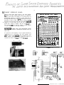
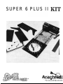
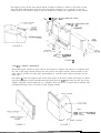
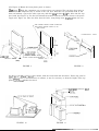
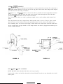
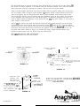
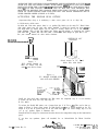
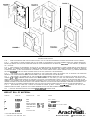
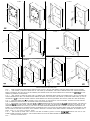
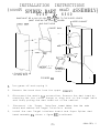
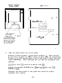
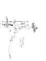
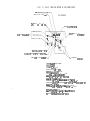
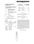
SE W/ICE
Page 1
SERVICE
Concerning
4500
and
6000
Series
February
WARNING--DISCONNECT
ELECTRICAL
BULLETIN
3,
POWER
English
1987
BEFORE
Mark
Dart
Games
_.
ATTEMPTING
SERVICE
Due to an error in printed board circuit layout, there is a
problem which may cause short life with the SC146D
triac in both
the 4500 and 6000 series game. The error causes the current to
drive the lamp to be supplied from the gate of the triac instead
of the normal terminals. Due to the fact that the device is
considerably oversized, in normal operation (with the 4500) the
gate would handle the current even though the device was electrically mounted on the printed circuit board upside down. T h e
failures were caused when the bulb burns out with the filament
falling across itself shorting and drawing a much higher current.
If the device had been on the board correctly, the 120 amp surge
capability of the triac would have most often saved the device
from
failing.
What to do:
The fix for the 4500 and 6000 is basically the same.
1.
2.
3.
4.
5.
6.
7.
8.
Unplug the game from the wall outlet1
Remove the power supply from the game.
Turning the power supply over, locate the small printed
circuit board under the chassis.
Remove the board from the chassis by unscrewing three
mounting screws.
The triac is held to the board with one screw and nut.
Remove screw and carefully unsolder the triac from PC
board.
Reinstall the triac in the same location but on the
opposite side of the board. You must use an insulator
(fig. 1) since the metal tab of the triac is now being
mounted on the foil side of the board. Resolder triac
and reinsert screw and nut.
Reinstall PC board into chasis
with three screws being
very careful not to pinch any wires as you are tightening
them.
Place power supply back into cabinet, attach plugs from
wire harnesses, fasten down with screws, and plug into
wall outlet.
Cont.
Page 2
Fig. 2 and 3 show before and after for the printed circuit board
for the 4500: fig. 4 and 5 show the 6000.
If there
Remember, you are working with 120 volts AC circuitry.
are any questions, please call before attempting this
This modification should only be attempted by
modification.
qualified technicians.
ARACHNID, INC.
Gene Harlan
Chief Engineer
,.
Fig. 1, Mica Insulator
Fig. 2, 4500 Series Before Modification
Top Side of Board
Fig. 3, 4500 Series After Modification
Bottom Side of Board
Fig. 4, 6000 Series Before Modification
Top Side of Board
Fig. 5, 6000 Series After Modification
Bottom Side of Board
SERVICE INFORMATION
CONCERNING THE 6000 SERIES GAME
3-26-87
To update the 6000 series game to use the shorter 5 l/2” T-10 40 watt lamps instead of the 11 112” T-8 40 watt
lamps, you will need to do the following:
d.
WARNING: UNPLUG THE GAME FROM THE WALL OUTLET BEFORE SERVICING!!!
1. Move the (2) lamp sockets located on the sides down to the lower end of the shadow box. The crimp-on
cormectors will have to be removed by cutting as close as possible to the connector located inside the back of
the game Wire nuts will be used to refasten these wires. The socket will bc pointing up instead of down. The
screw for the socket should be located about one inch up from the lower edge A new hole will have to be
drilled into the back panel for the wires. This can be done from the back of the game (plan ahead to get the
holes in the right spot). The Arachnid part number on this lamp is 11-0007.
2 . Aluminum reflective foil with adhesive back (commonly available from an automotive supply store) MUST
be installed between the lamp and the wood shadow box for two reasons:
A: HEAT - The tape spreads the heat and protects the wood.
B: LIGHT - It reflects the light giving twice the illumination on the target as compared to the
long bulbs without the foil.
The foil that WC arc using is 2 S/8” x 9” and is bent into an “L” (the long direction) before inserting in the
shadow box. TUG part number from Arachnid for the foil is 13-0069.
Although the short bulbs can be installed without moving the sockets down, the aluminum tape MUST bc
used due to the increased heat of the shorter bulb. Moving the sockets down helps to distribute the light more
evenly.
If there are any questions concerning this update, please call l-800-435-8319 (in Illinois l-815-654-0212).
Gcnc I I;trl;1n
Chief EnFinccr
The Originator of Electronic Darts
SERVICE
BULLETIN
Concerning 6000 Series English Rark
Dart Gases
June 6, 1988
WARNING--DISCONNECT
ELECTRICAL
POWER
BEFORE
ATTEBPTING
SERVICE
A problem has arisen concerning the location rhere the target interface board ribbon cable connects into the sain P.C.board on the 6000
and Super 6 Plus games.
Apparently, the trace that runs the controlling voltage for the target lasps is located directly beneath the
area where this ribbon cable Is plugged in. There is a thin coating of
insulating film covering this trace, but after a period of tiae this
coating can rear off, leaving the copper trace exposed. Due to the
construction of the Target Interface ribbon cable, vhen the coating is
no longer present, the rav edges of the ribbon say make contact vith
this copper trace, vhich can cause target lamp flicke'ring, sinulate a
stuck segment, or simulate a throvn dart. A stuck segment simulation
locks up the gaee if the ribbon sakes constant contact, but sany tises
the ribbon vi11 short momentarily vhen a vibration occurs to the P.C.
board, such as vhen throving a dart or touching the Select or Player
Change buttons. This type of short say result In the game shoving an
extra dart throvn In a round, or the gase nay reset during play.
What to do:
FIG.1
1. Turn off gane, and unplug fros wall outlet!
2. Disconnect the ribbon cable casing from the
T.I.board to the main P.C.board.(see
fig.11
3. Locate the trace that runs belov the ribbon
connector.(see fig.11
4. Using a piece of electrical tape, cover the
trace completely at the connector location,
and fold tape down over the P.C. board edge
(to keep connector from catching on tape).
5. Re-insert the ribbon cable into the header
on the main P.C.board.
6. Plug game into the vail, and turn it on.
7. When servicing the game in the future,
periodically check the placement of the
tape, to be sure it has not shifted.
If there are any questions regarding this or any other service problem,
please call ARACHNID, INC. at 800-435-8319 (in Illinois; 815-654-0212).
ARACHNID.
INCfi
Connie Reece
Design Engineering
Tech.
5.4 TARGET INTERFACE BOARD
The new switch matrix design requires a new target interface
PC. board. The target interface board reads the 19 conductors
from the switch matrix and transfers it to the main board. For
troubleshooting purposes it is important to know which pins on
the target interface board will give a particular score. Thii
information is listed in Table 1 and shown in Figure 12. Wit$
* the game in Test mode (at the end of test when dartkad 1s
sensitive) or in game mode, pairs of pins can be shorted and
opened with a jumper to simulate a dart hit (see Figure 11).
This procedure cm help determine whether a scoring problem
is in the switch matrix or the game electronics.
SWITCH MATRIX TEST CHART
1s - I N N E R StNGw Max
remove the swkh
and release. The LED
should flash and the game
T,= TRIPLE
‘-‘-I BULL
‘D e-38 II I
should score as If the
JPF
PIN
NOTE: m SCORE WILL NOT REGISTER UNTIL
THE JUMPER WIRE IS REMOVED FROM ONE OF
THE PINS.
lf a game has a stuck segment, it can be opened electrically by
disconnecting the 19 pin ribbon. The stuck segment’s score
will then register, and the darthead can be checked for the cause
of the problem. Another method of opening the switch is to
disconnect the ribbon cable from the Main P.C.board.
16
1
m.7
1
1 9
T9
‘S9
D4OSi
T4
IS4
01213s
14 I T12 lSl~Dl8~la T18 ISIB
8
D5osSTS
MO
fS508os6tB
TZJ IS20 Dl O S 1 Tl
--I
Is8
I
Is1
-I
J
Table 1 .
Figure 11
Figure 12
SUPER 6 PLUS II
P 0 Box 2901 0 Rockford. IL 61132-290
(IL) 815/654-0212 l 8001435-8319
This kit is designed to update a 4500 or 5000 Series English Mark Dart Game to a 6300 Series
(Super 6 Plus II). It will add the monitor and light shadow box to your game. The appearance of
your game, after the kit is installed, is similar to our 6000 to 6300 Series.
Tools required:
Hammer, Phillips and Straight Blade Screw Driver, 506, 114 & 3/32 Drill Bits, Wire Stripper,
Solder Wick, Pry Bar, Adjustable Wrench, Saber (Jig) Saw, Soldering Iron, Channel Lock Pliers,
Electric Drill, Wire Cutters, Solder.
STEP #l: SEPARATE THE UPPER CABINET AND THE LOWER CABINET, AND STRIP OUT
THE OLD COMPONENTS.
Remove the four (2 each side) carriage bolts that connect the upper cabinet to the lower cabinet.
Disconnect the coin door harness before disassembly. Remove the upper cabinet. The top light assembly must be removed from the upper cabinet; it will not be reused. Unplug the dart head pigtails and remove it temporarily.
Remove the following items (they are not reused):
Web - (if an Arachnid Web Kit has been added.)
Plexiglass Front Panel
Power Supply
Main PC Board
Main Wire Harness
Light Receptacle (Top Light Plug)
Target Interface Board (4500)
On/Off Switch (5000)
Inner Door w/Light PC Board & Target Interface Board (5000)
On the lower cabinet remove the Competitor strip and plexiglass instruction panel on 5000.
4500 I3OARD CAN I3E I’RYI~:I)
OFF WITHOUT MAKING CUTS
FIGURE 1
FRONT VIEW
FIGURE 2
I~XONT
VlEW
STEP #2: CABINET MODIFICATIONS
(See Figure 1) Cut and remove the remaining lower front support panel from the upper cabinet.
(See Figure 2) Cut away a portion of the upper cabinet bottom.
(See Figure 3) Cut and remove the lower cabinet as shown and remove the support block underneath it.
Using the hammer and pry bar, clean out the remaining 2” of the instruction panel. Be careful not
to damage the rest of the cabinet.
(See Figure 4) Pry off the side support blocks as shown in Figure 4. There is one block on each
side. The front channel must have the glue and staples removed. It is a good idea to cut the
staples flush on the inside. Trying to pull out staples may damage the appearance of the cabinet.
-+en
\ \‘\
‘u
SIDE SUPPORT
/“- B L O C K
~~ (6) l/4”--20x2” CARRIAGE BOLT
.
r (6) l/4”--20 FLANGE NUT
FIGURE 4
BRACKET
BOTH SIDES
/
(4)
>x
#8X1/2” FLATHEAD
WOOD SCREW
FIGURE 5
STEP #3: CABINET ASSEMBLY
Reassemble upper cabinet on lower cabinet (See Figure 5.) Using a side panel as a template, drill
the side of the upper cabinet. Fasten the side panel to the upper cabinet. Fasten bracket to the
lower cabinet and the new side panel approximately 5” from the front. Repeat procedure for the
other side.
(See Figure 6) The tray support rests on the front panel of the lower cabinet (See Figure 7). Holding the tray support in place and flush with the front, drill (2) 3132” pilot holes into the side of tray
support using the counter sunk hole as a template. Drive (2) screws to attach pieces together. We
recommend driving screws by hand to avoid splitting boards.
TRAY SUPPORT
DRILL
(2) #8 1 l/4” BLACK FLATHEAD
WOOD SCREW
OWER CABINET
FIGURE 6
FIGURE 7
(See Figure 8) Mount the front plastic panel as shown.
(See Figure 9) Slide the component tray in place above tray support. The coin door plug must go
underneath the component tray to attach to the coin door. With the tray positioned flush in the
front and without a gap on the sides, open tray and drill thru the three 5116 dia. holes into the support board (See Figure 4). Use the hole behind the monitor and the two holes closest to the power
supply (See Figure 10). Place the bolts thru the holes, using flange nuts thighten down the tray.
THE LOWER FRONT PANEL OVERLAPS
THE UPPER FRONT PANEL UP TO
THIS POINT
COMPONENT
HARNESS
i (4) A%--5J8”
PHILLIPS SCREW
MOUNTS FLUSH WITH
THE UPPER FRONT
FIGURE 8
FIGURE 9
(See Figure 11) I’lace top panel on cabinet, hold the front flush and drill holes. Fasten top panel to
upper cabirlet. Due to inconsistencies in cabinets, it may be necessary to shim the height of the top
pnncl. ~\pply froilt shadow box decal.
(2) l/4” 20X2”
CARRIAGE BOI,T
cD R I L L
NUT
FIGURE 10
FIGURE 11
TRAY
STEP #4: L!GIIT ASSEMBLY
(See Figure 12) Remove backing on foil and place it above pilot holes in cabinet. Be careful not to
cover lamp shield channels or the vent slot in the top panel, then screw down lamp socket. Repeat
procedure for the other lamp assemblies.
(See Figure 13) Drill (3) l/4" holes as close to the sides as possible and in the approximate location
of the lamp sockets. Run the black and white wire from the socket through the black tube then
through the l/4” drilled holes to the back of the cabinet.
The enclosed wire splices are used by placing stripped wires in and crushing with channel lock
pliers.
The lamp harness has three stripped wires held together with a wire tie. Using a splice, attach
the black wires to the black wire from the right lamp socket. Do the same for the white wires.
The remaining wires are for the other lamps. Match white wires with white and black with black
Screw in light bulbs and put shield on. The lamp harness can then be plugged into matching connector on main harness.
r -l
i
22”
. - - - -__ I/
8” API’ROX.
/
GRAY WIRE
’
n
PILOT
LIGHT SHIELD
CHANNELS
BLACK
FIGURE 12
FIGURE 13
STEP #5: WEB & DART ASSEMBLY
NOTE: DO NOT attach threaded rod before web is put in place.
Put the web in place and add the threaded rod from behind. Thread nut onto threaded rod to hold
web in place.
The Dart Head must be rotated 90 degrees. This will make the 11 become the 20. (See Figure 14)
The 20 has red single segments, so to conform with the standard segment colors, take the Dart
Head apart and rotate the segments one position. Do not rotate the switch matrix.
(Figure 15) Reassemble Dart Head and mount in game with the pigtails facing down. Using piece
cut out of upper cabinet in figure 2 and supplied “L” brackets mount support behind plastic front
panel, Plug pigtails into the Target Interface Board, install standoffs, and position board in the
area shown. Be careful to find a position that puts minimum strain on the pigtails. Peel backing
off the standoffs and attach below the Dart Head. (Figure 15) Optional speaker location may be
used on 5000’s without modification, on the 4500’s drill ten 5/16 dia. holes within a 3” dia. circle to
allow sound to come forward.
(Figure 16) The notch in the back door must be on the left side, looking from the rear of the game.
To accomplish this, the back door must be reversed. Cut the l/4” brace off flush with the bottom.
Add the new brace to the opposite side. The lock and speaker must also be..moved to the other side
of the door. The newer 4500 series will not have the speaker on the door; leave it where it is. Attach FCC label where shown in Figure 16. Connect the lamps, Target Interface Board, and
speaker to main harness and P.C. Board; close the cabinet back.
STEP #6: MODIFYING THE COIN DOOR
See the instructions on Coin Door Update.
ROTATE ALL SEGMENTS
ONE POSITION
*
OPTIONAL SPEAKER
LOCATION
DART HEAD
I
SEGMENTS
0
I
(8) #8 x l/2 FLAT
-
/17%*1 /
(2) L BRACKETS
FIGURE 14
N-
TARGET
INTERFACE
BOARD
FIGURE 15
RELOCATE
LOCK,
SPEAKER, AND
/ SPEARER
NEW BRACE ON
ATTACH FCC
/ LABEL HERE
OPPOSITE SIDE
THE NOTCII WILT,
If there are any questions regarding these instructiol
please call Arachnid, Inc. at l-800-435-8319
(in Illinois 1-815-654-0212).
HAVE TO
BE ADDED TO SOME 5000’s.
IF YOU HAVE TO CUT A
SLOT, REVERSING THE DO
IS NOT NECESSARY.
37-0130 Rev. c
FIGURE 16
P 0 Box 2901 0 Rockford. IL 61132.29(
( I L ) 815/654-0212 . 8 0 0 1 4 3 5 8 3 1 9
INSTALLATION INSTRUCTIONS FOR
DOUBLE BULLSEYE - ALL GAMES
Your Double Bullseye Accessory Kit should contain the following items:
1. Inner Bull (Black)
2. Outer Bull (Red)
3. Decal
(4. New Switch Matrix (Matrix is already installed on new double bull games)
Carefully remove the dart head from your dart game by removing the 4 bolts holding the dart
head in the game. Lay the dart head flat on a table, with the white backboard facing you.
HINT: Before removin the eight nuts holding the dart head together, place a piece of tape on
the heads of the screws 7segment side of dart head) to hold them in place after nuts are removed.
Refer to your game parts manual for illustrations on how this disassembly process is done.
Disassemble and reassemble dart head as follows:
a) Remove the 8 nuts holding the target back to the spider.
b) Remove the switch matrix.
c) Remove white molded matrix cushion (older dart heads use a clear vinyl gasket and a red rubber damper)
d) Check for dirt and broken tips between spider and cups. Install new double bullseye.
e) Clean and reinstall matrix cushion. The smooth side of the cushion comes in contact with the
segments.
IMPORTANT
THERE SHOULD BE A SMALL U SHAPE CUTOUT ON THIS CUSHION. POSITION IT TO
THE LEFT OF THE CENTER LOCATION HOLE AT THE “20” SEGMENT ON THE SPIDER
(BEHIND THE “DOUBLE 1” SEGMENT).
0 Ifyour kit includes a new Switch Matrix, install it with the tails on the left and the 9 pin connector on top. Store the old Matrix in a safe place. Ifyourkit does not contain a new Matrix, simply reinstall the old one in the same manner.
g) Clean and reinstall target back and 8 nuts, tighten only finger tight.
NOTE
BOLTS MUST BE FINGER TIGHT ONLY. ANY TIGHTER COULD CLOSE CONTACTS IN
THE MATRIX AND CAUSE INACCURATE SCORINGORNO SCORING AT ALL.
NOTE
ITISI~IPORT~TTOIiEEPDIRTOUTOFTHEAREABETWEENTHESPIDERANDSEG-
MENTS AS THIS CAN CAUSE NON-SCORING OR IMPROPER SCORING. ON A HEAVILY
PLAY-EDGAMEITISAGOODIDEATODOPREVENTIVEMAINTENANCEONAREGULAR
B~ISINTHEFOR~lOFDISSASSEMBLINGTHEDARTHEAD,CLEANINGANDREASSEM-
BLING. THIS CAN HELP PREVENT SERVICE CALLS IN BETWEEN REGULAR VISITS.
NOTE
ALTHOUGH THE DART HEAD IS DISASSEMBLED AND REASSEMBLED AS IN THE PAST
(WITH 4500 AND 5000 SERIES GAMES), WITH NEWER 4850’S, 6000’S AND 7000’S IT IS
INSTALLED WITH THE 3 LEADS INTHE DOWNWARD DIRECTION. THIS MEANS THAT
THE “20” ON THE YELLOW SPIDER IS NOT AT THE TOP. THE PROGRAM WAS
MODIFIED TO REFLECT THIS CHANGE. MAKE SURE THAT IF USING A DART HEAD
FROM AN OLDER SERIES GAME THAT THE RED AND BLACK SEGMENTS ARE IN
THEIR PROPER ORDER (SINGLE 20 IS RED).
ACTIVATING THE DOUBLE BULL OPTION
(Important--Skip Step A if modifying a 4800 series game. Go on to Step B.)
A. FOR 6000’s AND 7000’s
On 6000 and 7000 series games, there is a 4 position Dip Switch on the main P.C. Board. Some
older 6000 games may not have this switch installed. It should be located just above U20 on
your 6000 main P.C. Board (Above U18 on 7000 P.C. boards). Install one if it is not there already. Flipping SW3 of this Dip Switch (see Figure 1) will activate or deactivate the Double
Bull. SW3 ON = Double Bull ON; SW3 OFF = Double Bull OFF (Single 50 point Bull is on).
See your owners manual for other switch functions.
SW3FOR-
DOUBLE BULL IS ON
SWITCH IN “ON”
POSITION
__
U2O or U18
U8
(6000) or (7000)
1dl
u12
Figure 2
_
Switch location on P.C. Board,
Solder Side, 4800 Series
Figure 1
D.I.P. Switch Location on
Main P.C. Board, CPS side,
6000 & 7000 Series Games-
.
Figure 3
l
P.C. BOARD, SOLDER SIDE :
4500 AND 4800 SERIES
l
l
l
Install
Insulated
geyeper
ea
‘ole
er
l
l
Install the long decal strip underneath the Web above the component tray. It is not necessary
to remove the old decal. You may skip Step B.
B. For 4800’s:
To activate the Double Bull option, run a jumper from pin 17 of U8 to +5V. This can be done as
shown in Figure 3. Some newer games (in 4800 Series) ma have a switch installed on the P-C.
Board. If so it will be located near U8, on the solder side. o Pthe P.C. board. Simply flip it to the
“on” or “up” position. Figure 2 illustrates this.
Install the decal strip in a convenient location above the competitor strip on the instruction
panel.
If you have any questions, please call Arachnid, Inc. at l-800-435-8319 (In Illinois l-815-65402 12).
Part # 37-0124 Rev. B
The Originator of ElectronicDarts
P 0 BOX 2901 0 Rockford. IL 61
( I L ) 815/654-0212 . 8001436
FIGURE 3
FIGURE 4
INSTRUCTIONS FOR 5000
STEP 1
TURN THE GAME OFF AND UNPLUG FROM THE WALL OUTLET. UNLOCK AND REMOVE THE BACK DOOR FROM THE TOP CABINET.
STEP 2
(SEE FIGURE 1) FROM THE BACK SIDE OF THE GAME: (A) DISCONNECT THE PIGTAIL RIBBONS FROM THE TARGET INTERFACE
BOARD. (B) REMOVE THE NUTS AND WASHERS FROM THE FOUR CORNER BOLTS HOLDING THE DARTHEAD
TO THE CABINET. (C) REMOVE
THE DARTHEAD.
S T E P 3 (SEE FIGURE 2) (A) DISCONNECT YELLOW PLUG TO GAME SWITCHES. (B) DISCONNECT PLAYER CHANGE SWITCH FROM MAIN CIRCUIT BOARD. (C) REMOVE AND DISPOSE OF RIBBON CABLE BETWEEN LAMP BOARDS AND TARGET INTERFACE BOARD. (D) REMOVE
PLEXIGLASS FRONT (IT WILL BE NECESSARY TO REMOVE THE UPPER CABINET FROM LOWER CABINET FIRST). (E) REMOVE REMAINING
NUTS AND CARRIGE
BOLTS THAT HELD THE DART HEAD TO THE TOP (THESE WILL NOT BE REUSED).
STEP 4
(SEE FIGURE 3) CUT 9 l/4” FROM THE BOTTOM OF THE PLEXIGLASS FRONT. BE CAREFUL NOT TO SCRATCH THE GRAPHICS.
REINSTALL THE LOWER PORTION TO THE UPPER CABINET. THE TOP PORTION WILL NOT BE REUSED.
STEP 5
(SEE FIGURE 4) (A) SCREW TWO OF THE FOUR (l/4” X 2 l/4”) THREADED RODS INTO THE LEFT SIDE OF THE WEB. (B) THE TWO
LONGER (l/4” X 2 3/4”) THREADED RODS SCREW INTO THE RIGHT SIDE OF THE WEB. (C) PLACE THE WEB AGAINST THE FRONT OF THE
GAME, WITH THE RODS GOING THROUGH TO THE BACK. (D) USE THE 4 NUTS REMOVED IN STEP 3, FIGURE 2, TO SECURE THE WEB TO THE
CABINET. IT IS POSSIBLE DUE TO MANUFACTURING TOLERANCES THAT THE 4 HOLES (FOR THE RODS) MIGHT HAVE TO BE ENLARGED TO
CENTER THE WEB TO THE DART HEAD HOLE IN THE CABINET. REINSTALL THE DART HEAD USING ORIGINAL HARDWARE. RE-CONNECT THE 3
MATRIX LEADS TO THE TARGET INTERFACE BOARD, THE YELLOW PLUG FOR THE GAME SWITCHES, AND THE PLAYER CHANGE SWITCH.
STEP 6
(SEE FIGURE 5) USING THE 4 HOLES IN THE WEB AS GUIDES, (A) DRILL 4 HOLES (3/32” - ,096”) THROUGH THE TOP OF THE
CABINET FROM THE FRONT. (B) INSTALL THE 4 WOOD SCREWS TO HOLD THE WEB CORNERS TO THE TOP CABINET.
STEP 7
REPLACE THE WING NUTS ON THE LONGER STUDSREPLACE THE BACK DOOR,
WEB KIT BILL OF MATERIAL
QUANTITY
PART NO.
DESCRIPTION
1’
ooa000-33
WEB
6000
1*
00-4500-33
WEB
4500 & 5ooo
4
14-0082
WOOD SCREWS
#a X 1 l/4”
4
14-0061
THREADED ROD
l/4” X 2 l/4”
4500&6ooo
2
14-cm3
THREADED ROD
l/4” X 2 314”
5000
SERIES
1++
1
16-0071
3a-0038
DECAL
INSTRUCTIONS
6000
SERIES
l
ONLY ONE WEB IS SUPPLIED
l
* SUPPLIED IN 6000 WEB KITS ONLY
SIZE
USAGE
SERIES
SERIES
ALL
5 0 0 0 U S E 2 ONLY
ALL
Revision B 38-0008
0 1988 Arachnid, Inc.
FIGURE 1
FIGURE
FIGURE 2
FIGURE 4
r-l
FIGURE 6
INSTRUCTIONS FOR 4500 AND 6000
STEP 1
TURN THE GAME OFF AND UNPLUG FROM THE WALL OUTLET. UNLOCK AND REMOVE THE BACK DOOR FROM THE TOP CABINET.
STEP 2
(SEE FIGURE 1) FROM THE BACK SIDE OF THE GAME: (A) DISCONNECT THE PIGTAIL RIBBONS FROM THE TARGET INTERFACE
BOARD. (B) REMOVE THE NUTS (WITH NYLON INSERTS) AND WASHER FROM THE FOUR CORNER BOLTS HOLDING THE DARTHEAD
TO THE
CABINET. (C) REMOVE THE DARTHEAD.
STEP 3
(SEE FIGURE 2) FROM THE BACK SIDE, (A) REMOVE THE REMAINING NUTS FROM THE CORNER BOLTS. (B) TAP THE ENDS OF
THOSE CORNER BOLTS UNTIL THE HEADS BULGE UNDER THE DECAL ON THE FRONT. (SEE FIGURE 3) FROM THE FRONT SIDE, (A) CUT APPROXIMATELY 3/4” DIA. CIRCLES AROUND THE BOLT HEADS WHERE THEY BULGE. (B) REMOVE THE 4 BOLTS (THESE WILL NOT BE REUSED).
STEP 4
(FOR 6000 GAMES ONLY - SEE FIGURE 4) APPLY THE DECAL TO THE FRONT OF THE TOP CABINET. POSITION IT ALONG THE BOTTOM, COVERING THE STRIPE AND THE “ARACHNID” NAME ON THE EXISTING DECAL.
S T E P 5 (SEE FIGURE 5) (A) SCREW THE FOUR (l/4” X 2 l/4”) THREADED RODS INTO THE WEB. (B) PLACE THE WEB AGAINST THE FRONT OF
THE GAME, WITH THE RODS GOING THROUGH TO THE BACK (WITH THE 6000, THE WEB MUST BE PLACED AGAINST THE FRONT OF THE
GAME BEFORE ATTACHING THE 4 RODS). (C) USE THE 4 NUTS AND WASHERS REMOVED IN STEP 3, FIGURE 2 TO SECURE THE WEB TO THE
CABINET. IT IS POSSIBLE DUE TO MANUFACTURING TOLERANCES THAT THE 4 HOLES (FOR RODS) MIGHT HAVE TO BE ENLARGED TO CENTER THE WEB TO THE DART HEAD HOLE IN THE CABINET. REINSTALL THE DART HEAD USING ORIGINAL HARDWARE. RE-CONNECT THE 3
MATRIX LEADS TO THE TARGET INTERFACE BOARD.
STEP 6
(SEE FIGURE 6) USING THE 4 HOLES IN THE WEB AS GUIDES, (A) DRILL 4 HOLES (3/32” - .096”) THROUGH THE TOP OF THE
CABINET FROM THE FRONT. (B) INSTALL THE 4 WOOD SCREWS TO HOLD THE WEB CORNERS TO THE TOP CABINET.
STEP 7
REPLACE THE BACK DOOR.
INSTALLATION INSTRUCTIONS
(SUPER ~DER'DART HEAD ASSEMBLY)
6200
& 6300
G A M E M U S T B E A 6 2 0 0 O R 6 3 0 0 TO U P G R A D E T O T H E S U P E R S P I D E R
( M U S T C O N T A I N T H E C O I N PC B O A R D >
UPPER CABINET
OLD DART HEAD
h
TARGET BACK
a
-
-
-
,A•
-
_.
_C-- --
+
,-.
=-:;
_,-*
----
-----
_-Zi------_A--kl------
’
k,,
T
A
I
L
CONNECTIONS
PI’
TARGET
INTERFACE
BOARD
4 F L A N G E N U T S -J
OR WING NUTS
F I G U R E #1
1,
Turn game off and unplug it.
2.
Remove the back door from the upper
3,
D i s c o n n e c t t h e m a t r i x tail c o n n e c t i o n s , R e m o v e t h e d a r t h e a d b y
removing the four corner flange or wing nuts on the target back
and firmly pulling the dart head out of the cabinet.
4.
Disconnect
the
5,
Interface board
T a r g e t Interface
Target
board and remove the
c:abinet,
ribbon
board,
from
Install the new Target Interface board and Super
h e a d a s s e m b l y as s h o w n i n f i g u r e #2, ( c o n t i n u e d >
-l-
the
main
Spider
dart
23900 REV,
D
UPPER CABINET
(BACK VIEW>
MAIN
BOARD .
0
D
P
3.3K RESIS%R N E T W O R K
REPLACES DIODE NETWORK
7
L
G R A Y CLIP---1
NEW TARGET
INTERFACE BOARD
THE NEW TARGET INTERFACE
BOARD MUST BE INSTALLED
SO THAT THE GRAY RIBBON
CONNECTOR IS ON THE LEFT,
AND THE CABLE OVERLAPS
THE P.C. BOARD. SECURE
IT IN PLACE WITH THE
GRAY CLIP PROVIDED.
6.
0
..
u15
E P R O M P / N 01-0188
6 3 0 0 T V3.0
Take the main board out of the game.
Most boards
R e m o v e r e s i s t o r n e t w o r k US a n d d i o d e n e t w o r k U6.
do not have sockets for these chips so they must be unsoldered,
U s i n g a small s i d e c u t t i n g p l i e r s , c u t a l l t h e l e g s o f e a c h c h i p a n d
Each individual pin can then be unsoldered and
remove the body,
removed,
Install t h e n e w 3.3K r e s i s t o r n e t w o r k c h i p U6,
R e m o v e t h e o r i g i n a l E P R O M f r o m lJ15 a n d install t h e n e w V3,O
EPROM at lJ15.
Reinstall the main board in the game and check for proper
operation and scoring,
-2-
Concerning all Series 6000 and 7000 English Mark Dart Games
January 18, 1990
WARNING---DISCONNECT ELECTRICAL POWER BEFORE ATTEMPTING
SERVICE
We are recommending that the main fuse FS3 be upgraded from a 1.5 Amp
Slow Blow to a 2.0 Amp Slow Blow. Due to slight variances in components,
some games draw more current than others.
When these games are
connected to high line voltage, the current draw gets even higher, close to the
rating of the 1.5 Amp fuse. After a period of time, the fuse will blow, even
though the rating may not have been exceeded.
Since all of the components in the power supply are rated at a minimum of 2
Amps, no damage will occur as a result of this change. Do not exceed the 2.0
Amp rating, however. If the 2.0 Amp fuse blows, there is a definite problem
in the power supply, indicating it needs to be serviced by a qualified
technician.
If there are any problems regarding this or any other service problem, please
call ARACHNID, INC. at 800-435-83 19 or in Illinois at 8 15-654-02 12.
Arachnid, Inc.
John Farmer
Engineering Technician
6421 Material Ave
Rockford, 11 61111
8 15-654-02 12
800-435-83 19
m,---------
Tp-----a-
-----,n-------
--(f----------------- (=a---
------------_
------a
-de
VIEW OF BOARD FROM THE BOTTOM OF THE POWER SUPPLY
US VERSION
CONNECT BLUE VIRE TO SVITCH QOT SIDE,
CChNECT
YELLOV VIRES CPP. SIM T O FUSE
CONNECT VH:li WCC FROM
SSCDER
CAP. TO
NEU?
Aw
WT
CGhhECT
AS
CGWIECT
AiiACH
CiiEY
VIRE FROM BCiTON
TiE BLACY
VlRE FRCH
T H E
CF ‘TC R4’ TO CCNNECTCR
THE
XFMR
VIRE AT ‘TO R4’ T O TERH.
“3 CN P O T .
XiNR
PIN 12
CONNECT VIRE AT ‘TO R4’ TO TERH “2 GN POT. -/
CUT TRACES AS SHOVN (2 PLACES>
CONNECTING POVER CORD LEADS TO PC BOARD;
CONNECT BLACK TO HOT
CONNECT GREEN TO GND
CONNECT VHITE T O NEUT
SOLDER ALL CONNECT106 IN RACE.
SCLOER CAP. TO NEUT AN0 MT AS SWVN
C(INNECTIffi POT. USE GRANGE VIRCS FROM SIDE
o f
Bwm opp. THAT wow AaovC
CONNECT VIRE AT ‘TO R4’ WAR CUT OUT T O TERn IO ON PO,.
COhNECT
VIRE AT ‘TO R4’ T O TERM 12 ON POT.
ATTACH GREY VIRE FROM BUTTCN OF ‘TO R4’ T O CDU~ECTI)R PIN “2
CtNNECTlffi THE TbviSJCRnER TO THE BOARD
CONNECT VHITE VIRE FROM THE XFHR T O CONNECTIGN
NEAR THE SVITCH CONNECTlON
CONNECT BLACK VIRE FROM THE XFNR TO CONNECTION NEAR THE CAP. TAGEO ON TN PDVER L E A D
CONNECT BLACK VIRE VITH WUTE STRIPE FRON THE XFRH 10 THE COw,ECTID( NEAR THE CONNECTID., k&WED ‘TO R4’
CONNECTIN; TH F U S E TO T H E BOAR0
CONNECT YELL&’ VIRE TO FM CZW+ZCTION ON BOARD AND TOP SIDE CF THE FUSE
CONNECT YELLOV VIRE TO FUSE UNFECTION ON BOARD AND BOTTON SIDE SIIE OF THE FUSE
CONNECTIIG TK SVITM T O THE B O A R D
CIINNECT
BLUE VIRE FROM HOT SIDE OF SVlTCH TO THE #2 TERNINAL
CONNECT BLUE VIRE FROM XiNR SIDE 10 TERN. @I ON THE SVITCH
TRIM
EXCESS VlRC FRM PLL ABOVE CONNCCTIONS
VHEN CONPLETEO
Ui Te SVlTCH
V I E W O F B O A R D F R O M T H E B O T T O M OF T H E P O W E R S U P P L Y
OVERSEAS VERSION
CUMCT
ChNECT
CnNHcCT
&WE
cchMcT YELLOV
V!RzS
BL4ci(
B L U E VIRZ
VIRE
T O
wws SIDE>
W I T C H WOT rra,
CPP. SIDC T O
V!RE k!iY VWITE
T O SVITCH
S T R I P E
F U S E
F R O M XFPR
CmNECi
“ERE AT 70 R I ’ TO TERH. 42 ON P O T . A T T A C H CREY VIRC FRCH EOTTDH CF ‘ T O R I ’ T O CCNMCTCR
P I N 12
ccwECTING
WYER CcRil LEA35 TO P C B O A R D :
CCWNECT RROW T
O
tdi7
Cm.NCT
XLLDV VITH GREEti S T R I P E T O GND
CCWYECT B L U E T O NUT
SOLDER ALL CONNECTlCHS
IN PLACE.
SR!xR CAP T
O
MU1 WD wr AS SHOVN
CU8ECTING
P O T . USE C#.WX
VMS F R O M SIK
a mm OPP. TMT hew
AawE
CDNCT WIT AT ‘ T O R4’ M A R C U T N T 10 TEW “3 Di PDT.
Ct,+SCT
VIRC A T
‘ T O
R4’ TO TERM. 12 EN WT.
ATTAM
CXY VIRE F R M HiiT.DF ‘ T O R I ’ T O CChhECTOR
P I N MB
CChMCTIW X-E T%WSFORHER
T
O
TN WD
CmmcCT
VHlTE VIRE FRM THX XTM T O COH~ECT,OH
N E A R TH NIT04 C O N N E C T I O N
UEPECT BLACK VIRE FRM TX XsWR T
O
COliHECTlOH
NEAR TH CAP. TAGED PI TX PIIVERL
E
A
D
CONC,
LACK VIRE VITH VHITE S T R I P E FRC% T H E XfRH T O TK uNvECT,DI N E A R T H E CDEECTIOH
CUwXTING 1% F U S E T O T H E EDRD
CDWCT IELLOV VIRE T O
FUSE COHHECTloH O H
BOARD AND Top SIDE (r THE F U S E
CCwXCT
YELLO”
VIRE TO F U S E CONHECTlOH O H BWRD AND BOTTC” SIDf S I D E CF T H E fUSE
CuwfCTIM; Tt+r SVITCH T
O
TX BDaRD
u*NC, B L U E VIRE
FRCM H3T S I D E W SVITM T O T H E 12 TEBWAL
-CT BC”E VIRf fRD( X0Cf SIDE T O
TER4 I, O H
T H E
WITCH
TRlW
E X C E S S VlRE
F R O M A L L ABOVE
CCHHECTIONS
VW3 CD+=lETEO
CN TN W I T C H
WJKED
‘ T O R1’