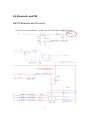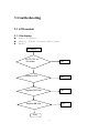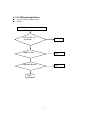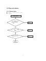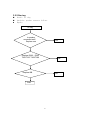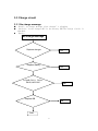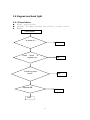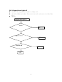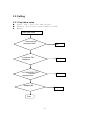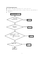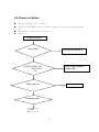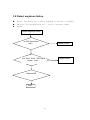
1
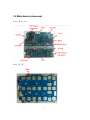
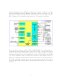
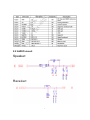
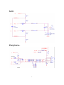
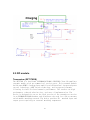
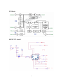
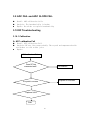
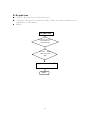
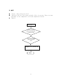
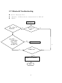
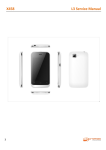
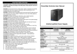
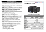
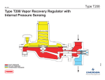
M810C Service Manual Document Type : Maintenance Training Document Name : M810C Service Manual Version : 1.0 Date:2014/11/07 1 1 PRODUCT CHARACTERISTIC ............................................................................................................ 3 1.1 OVERVIEW ............................................................................................................................................. 3 1.2 FUNCTIONS ............................................................................................................................................ 3 1.3 TECHNOLOGY DETAILS.........................................................................................错误!未定义书签。 1.4 MAIN-BOARD PLACEMENT .................................................................................................................... 4 2 CIRCUIT .................................................................................................................................................... 5 2.1 SYSTEM OVERVIEW ............................................................................................................................... 5 2.2 AUDIO CIRCUIT .................................................................................................................................... 7 2.3 LCD MODULE........................................................................................................................................ 9 2.4 BATTERY AND CHARGER ........................................................................................................................ 9 2.5 RF MODULE ......................................................................................................................................... 10 2.6 BLUETOOTH AND FM .......................................................................................................................... 12 3 TROUBLESHOOTING .......................................................................................................................... 13 3.1 LCD MODULE...................................................................................................................................... 13 3.2 RING AND VIBRATOR............................................................................................................................ 15 3.3 CHARGE CIRCUIT ................................................................................................................................. 17 3.4 KEYPAD AND BACK LIGHT ................................................................................................................... 18 3.5 CALLING ............................................................................................................................................. 20 3.6 POWER ON FAILURE ............................................................................................................................. 22 3.7 DOWNLOAD FAILURE ........................................................................................................................... 23 3.8 DETECT EARPHONE FAILURE................................................................................................................ 24 3.9 ADC FAIL AND ADC SLOPE FAIL .................................................................................................... 25 3.10 RF TROUBLESHOOTING ..................................................................................................................... 25 3.11 BLUETOOTH TROUBLESHOOTING ...................................................................................................... 28 3.12 FM TROUBLESHOOTING .................................................................................................................... 29 2 1 Product Characteristic 1.1 Overview M810C is dual-frequency mobile main-board. It supports 1.77(128*160) and 2.0(176*220) LCD module, digital camera and MMS module, 64-chord ring, MP3, USB and many kinds of useful functions – multi-language input, phone note, ck/alarm clock, calculator, games,FM radio,Bluetooth. 1.2 Functions M810C main-board system overview: z 97mm*36mm z GSM900/DCS1800 dual-frequency mode; z Supports 2.0/2.4 LCD module z Supports digital camera; z Supports MP3 music; z Supports MPEG4 format movies; z Extensible Memory: T_FLASH card; z Supports longtime sound record; z Earphone connector; z Electric torch; z Supports MMS; z 64-chord ring; z Short message; z Many games integration; z Rings, volume, desktop individuation setup. 3 1.4 Main-board placement M810C_MB_Bottom M810C_MB_TOP 4 2 Circuit 2.1 System Overview MT6261M is a feature-rich and extremely powerful single-chip solution for high-end GSM/GPRS capability. Based on the 32-bit ARM7EJ-STM RISC processor, MT6261M’s superb processing power, along with high bandwidth architecture and dedicated hardware support, provides a platform for high-performance GPRS Class 12 MODEM application and leading-edge multimedia applications. 5 The power management unit (PMU) manages the power supply of the entire chip, such as baseband, processor, memory, SIM cards, camera, vibrator, etc. The digital part of PMU is integrated into the analog part (see the figure below). PMU includes the following analog functions for signal processing: There are three types of LDOs in PMU of MT6261A PMU. The analog LDO is optimized for low-frequency ripple rejection in order to reject the ripples coming from the burst of RF power amplifier. The digital IO LDO is a linear regulator optimized for very low quiescent current. The single-step RTC LDO is a linear regulator that can charge up a capacitor-type backup coin cell, which also supplies the RTC module even at the absence of the main battery. The single-step LDO features reverse current protection and is optimized for ultra-low quiescent current while sustaining the RTC function as long as possible 6 2.2 AUDIO circuit Speaker: Receiver: 7 MIC: Earphone: 8 2.3 LCD module TFT mode: 1.77QQVGA/2.0 QICF Resolution: 128*160/176*220 Dot Back light mode: Write LED 2.4 Battery and charger (1) Battery The Li-on battery is advised, 3pin. Dimension and capacity is decided by mechanism solution. (2) Charge process The switch charger is recommended for S33 with USB cable can be used too. The charge process is optimized for Li-on battery specially that include pre-charge, constant current charge and constant voltage mode. It can protect battery and extend usage life of battery. 9 2.5 RF module Transceiver (RF7170DS) The RF7170D is a dual-band (EGSM900/DCS1800) GSM/GPRS Class-12-compliant transmit module with two symmetrical receive ports. This transmit module builds upon RFMD's leading power amplifier with PowerStar® integrated power control technology, pEMT switch technology, and integrated transmit filtering for best-in-class harmonic performance. The results are high performance, reduced solution size, and ease of implementation. The device is designed for use as the final portion of the transmitter section in an EGSM900/DCS1800 handset and eliminates the need for a PA-to-antenna switch module matching network. The device provides 50 matched input and output ports requiring no external matching components. 10 RF Block: M810C RF circuit: 11 2.6 Bluetooth and FM M810C Bluetooth and FM circuit: ANT 12 3 troubleshooting 3.1 LCD module 3.1.1 No display Detail: no display Analysis: LCM FPC is broken; LCM is broken Repair: No display Is LCD FPC ok? Re-solder OK Replace LCM OK Replace DSP chip OK Replace BB chip OK Over 13 3.1.2 LCM back light failure Detail: LCM back light failure Repair: LCM back light failure Is LCD FPC ok? Re-solder OK Replace LCM OK Replace BB chip OK Over 14 3.2 Ring and vibrator 3.2.1 Vibrate failure Detail: vibrator doesn’t work Repair: Vibrate failure Is Vibrate ok ? Dose it connect Ok? Is OK C411 solder joint? OK Replace BB chip OK Over 15 3.2.2 No ring Detail: no ring Analysis: speaker connects failure. Repair: no ring Is speaker connected well? Replace one OK Replace R202,R203 T206 T207 T208 T209 OK Replace BB OK Over 16 3.3 Charge circuit 3.3.1 No charge message Detail: no charge message after charger’s plugging Analysis: Is the charger OK? Is the battery OK? The charge circuit is abnormal. Repair: No charge message Replace charger OK Replace Battery OK Is R440,R411, R414, R410,U403 OK? OK Replace BB OK Over 17 3.4 Keypad and back light 3.4.1 Press failure Detail: press failure Analysis: The dome is broken. The side key is short circuit Repair: Press failure Is dome ok? OK Clean dome or replace one OK Is side key short circuit? OK Replace BB OK Over 18 3.4.2 Keypad back light off Detail: The keypad back light is always off Analysis: LEDs are broken. The current control resistance is cold solder joint. Repair: Keypad back light off All off? OK replace R216 OK Replace BB OK Over 19 3.5 Calling 3.5.1 Can’t hear voice Detail: Can’t hear voice when calling Analysis: The receiver connect badly or broken Repair: Can’t hear voice Dose receiver connected well? OK Is receiver OK? Replace it OK Is C208 C209 T228 T229 OK? Replace them OK Replace BB OK Over 20 3.5.2 Can’t send voice Detail: The other side people can’t hear your voice Analysis: The MIC connect badly or broken. There are some problems in MIC circuit. Repair: Can’t send voice Dose MIC connected well? OK Is MIC OK? Replace it OK Is R212,R217,C222, C227,B201, B202 ,R213,R209 ok? OK Replace BB OK Over 21 3.6 Power on failure Detail: Mobile can’t power on Analysis: The 26M crystal is broken. The power-on-off key dome is broken. The baseband or flash chip is broken. Repair: Power on failure Big current? Find short current point Is VDD,VCORE ,VIO , VM,VTCXO ok? Power supply problem Replace BB 26M crystal ok? Replace them Download again? Over 22 3.7 Download failure Detail: Can’t download code to mobile Analysis: The 26M crystal is broken. The power-on-off key dome is broken. The baseband or flash chip is broken. Repair: Download failure Is VDD,VCORE ,VIO , VM,VTCXO ok? Power supply problem Replace BB Replace X601 26M crystal ok? Replace BB Download again? Over 23 3.8 Detect earphone failure Detail: The mobile can’t detect plugging in and out of earphone. Analysis: The baseband chip can’t receive interrupt signal. Repair: Detect earphone failure Is J205 connected well? Replace J204 Are R211 R201 R207,B208 Solder joint? Replace BB Over 24 Replace them 3.9 ADC FAIL and ADC SLOPE FAIL Detail: ADC calibration fails. Analysis: The baseband chip is broken Repair: Re-solder or replace baseband chip 3.10 RF Troubleshooting 3.10.1 Calibration A. AFC calibration Fail Detail: AFC calibration Fail. Analysis: RF test line connects badly. The crystal and components beside are broken or cold solder joint. Repair: AFC calibration Fail Dose RF line connected well? Re-connect Replace or re-solder Is crystal in reverse Replace U603 Over 25 B. Rx path loss Detail: Rx path loss calibration Fail Analysis: RF test line connects badly. There are some problems in the components at RX channel. Repair: Rx path loss Are RF test port J601, and the RF ant connected well? Are U603 and RX path component OK? Replace or re-solder BB Over 26 C. APC Detail: APC calibration Fail Analysis: RF test line connects badly. PA is in reverse. There are some problems in the components at PA and components beside. Repair: APC Fail Are RF test port P601,and the RF ant connected well? Are U603 and RX path component OK? Replace or re-solder BB Over 27 3.11 Bluetooth Troubleshooting Detail: Bluetooth Fail Analysis: Is Bluetooth ant connected ok? Is U101 ok? Repair: APC Fail The voice is abnormal N Are C701, C708,c709,L · 704,L705, R705 and the ANT ok? BT Can not open? Y N Replace them Y Y Is BB IC ok? N Replace or re-solder it Over 28 3.12 FM Troubleshooting 1. Detail: FM Fail Analysis: Are BB1C and the ant OK? Repair: Earphone FM Fail Earphone connected ok? N Replace or re-solder Y N Are R237,B211 ok? Y Replace BB Over 29 Replace or re-solder 3. EZ-FM Fail GSM antenna connected well? N Replace or re-solder Y N Are U701 and the around components OK? Y Replace BB Over 30 Replace or re-solder