1
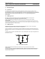
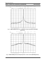
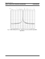
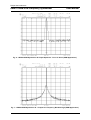
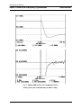
USER MANUAL
UMA1015AM
Low Voltage
Dual Synthesiser
CTT/97001
Guidance to Assembly and Operation
Preliminary Technical Report
Pascal Hugues
Technical Marketing
Telecommunication IC’s
Caen, France
Date: May 23rd, 1997
Philips
Semiconductors
Philips Semiconductors
UMA1015AM Dual Frequency Synthesizer
User Manual
1. Differences with the UMA1015M Last Version
• The minimum digital and charge pump supply voltages are 2.7 V (VCC ≥ VDD). It was 2.6 V when
using the UMA1015M.
• For the 400 to 1100 MHz RF frequency range, the minimum RF input signal voltage is 50 mV rms,
for the complete supply range. With the UMA1015M, the minimum RF input level is 100 mV rms
when the digital supply is greater than 3.5 V.
• The operating ambient temperature range is -30°C to +85°C for both synthesisers. For the
UMA1015M, it was 0 to +85°C with the synthesiser B supplied by a digital voltage greater than
4.5 V.
• The common reference divider can be driven by a simple quartz since an internal oscillator / buffer
is designed on the UMA1015AM. With the UMA1015M, it was just possible to use the VTCXO. A
register (address 1000 ; bit p15) was added to keep this internal oscillator / buffer ON when both
synthesisers are in power down if desired. After the supply voltage is switched on, the bit p15
(address 1000) is preset to 0.
• A solution has been implemented with the UMA1015AM design which permits to have independent
synchronisation for both synthesisers. So, if one synthesiser is in power down condition, then when
it is reactived, the main divider will synchronise with the reference divider in such a way as to
avoid large random phase errors at the phase comparator, independent of the state of the other
synthesiser (power up or power down). With the UMA1015M, when one synthesiser is already in
power up, and the second is powered up, it restarts with a random phase error at the phase
comparator.
• When the UMA1015AM is turned off, the phase detectors of A or B synthesisers are synchronised
with the charge pumps. This avoids powering down the synthesisers whilst they are sinking or
sourcing current pulses to the loop filter.
• For the UMA1015AM, the out-of-lock condition is flagged for a phase error greater than
approximately 15ns and is released after the first cycle with a phase error less than 25ns. For the
UMA1015M, the out-of-lock condition is flagged when the phase error is greater than 80 cycles of
the relevant RF input (TOOL). The out-of-lock flag is only released after the eight reference cycles
where the phase error is less than TOOL.
• The minimum RF input frequency is 45MHz with a input level higher than 0dBm. For the
UMA1015M, the minimum input frequency is 50MHz.
As the UMA1015AM is pin to pin and software compatible with the UMA1015M, it is expected that the
latter can be replaced in your application by the UMA1015AM without modification.
2
Philips Semiconductors
UMA1015AM Dual Frequency Synthesizer
User Manual
2. Guidance to Assembly and Operation
2.1. Introduction
The UMA1015AM is a low power low voltage single chip solution to a dual frequency synthesiser used
in radiocommunications. Designed in a BICMOS process, it operates from 2.7 (3 NiCd cells) to 5.5V.
The UMA1015AM contains all necessary elements with the exception of the quartz, VCO and loop
filter components to build two PLL frequency synthesisers.
It is intended that the dual synthesisers operate in the 50 to 1100 MHz range. The reference divider
uses a common part, an extra divide-by-2 block allows a reference comparison frequency for
synthesiser to be half that of synthesiser A. For each synthesiser, fully programmable main and
reference dividers are integrated on chip. Fast programming is possible via a three wire serial bus
with clock speeds up to 10 MHz.
The common reference divider can be driven by a VTCXO or a simple quartz since a internal
oscillator / buffer is designed in the UMA1015AM. When using a VTCXO, the inverted clock signal is
present on pin fXTALO with a suitable pull-up resistor.
The programmable charge pump currents are fixed by an external resistance RSET (at pin ISET). Only
passive loop filters are necessary, the charge pumps function within a wide voltage compliance range
to improve the overall system performance.
Each synthesiser can be powered down independently via the bus to save consumption.
A voltage doubler was designed to supply the charge pumps at a higher level than the nominal
available supply.
The enclosed demonstration board is an universal tool to demonstrate and evaluate the UMA1015AM
under several conditions.
Together, with the Philips 3-Wire bus and the UMA1015AM demonstration software, a quick and easy
starting is provided. The enclosed application information is preliminary and corresponds to the
AMPS and GSM standards. However, the demonstration board may easily be configured for other
digital cellular or cordless systems like TACS, CT1, PDC, etc...
We hope that you will find no problems in realising this evaluation set-up and will come quickly to an
application that fits perfectly to your needs.
2.2. Assembly
Assembly is done according to the UMA1015M application note (ETT/AN93016) which comes with the
demonstration board. Please note that the board may be assembled with VCO’s of different style. The
existing version of the board can hold surface mount VCO’s (e.g. ALPS URAX8, Murata MQE001
type). Since the VCO and the VTCXO use a common on-board supply rail, it is recommended to
select both components with the same supply voltage specification.
The loop filter design depends on the system requirements and the used VCO’s. A loop filter
calculation program has been written for use on IBM PC (and compatible). It is included with the three
wire bus control software diskette (‘Tool | Calculate filter’ menu option). It uses the same cook book
method as described on the UMA1018M or UMA1021M application notes.
3
Philips Semiconductors
UMA1015AM Dual Frequency Synthesizer
User Manual
2.3. Getting Started
1. Connect the Philips 3-wire interface board with the serial printer port (LPT1) of your PC. Copy the
two files (BUS3WIRE.WB and BUS3WIRE.EXE) onto your hard disk or run the software from the
disk. Type BUS3WIRE to start. Select UMA1015AM option in the ‘DEVICE TYPE’ menu. Verify
that the displayed window is well configured as you wish.
2. Connect the interface card with the UMA1015AM demonstration board.
3. Connect the board to a 7.5V well regulated and low noise power supply.
4. The UMA1015AM demonstration board is operational now and the two PLLs should be locked.
5. Start your synthesiser evaluation...
If you need assistance or do have any questions or comments don’t hesitate to call your local Philips
Semiconductors representative.
4
Philips Semiconductors
UMA1015AM Dual Frequency Synthesizer
User Manual
3. Technical Report
3.1. Introduction
The AMPS (Advanced Mobile Phone System) application has been used as a vehicle for this
technical report, this allows to compare its performance with the last UMA1015M version, which are
summarised page 18 of the UMA1015M application note. But the UMA1015AM should also find use in
digital cellular and cordless systems like GSM, PDC, etc...So, a typical GSM application is
demonstrated.
3.2. AMPS Application
The same component part list than used on the UMA1015M application note (report N°:
ETT/AN93016) was used to assembly the demonstration board.
Table 1 summarises the measurement results, Fig. 2 to Fig. 5 show some of the actual
measurements.
Good loop filter grounding is critical. On the demonstration board, breakthrough performance was
improved by providing a better ground connection to the loop filter capacitor C4 by drilling a through
hole to the ground plane in closer proximity.
3.3. GSM Application
Experiments show that higher charge pump current gives better close in noise. So maximum
available charge pump currents are used in this application.
For the synthesiser A, a VCO sensitivity of about 26 MHz/V and a typical comparison frequency of
200 kHz have been assumed. The charge pump current has been selected to 2.4 mA/cycle (CRA bit
set to 1).
Loop filter values have been calculated with the ‘Tool | Calculate filter’ menu option integrated in the
BUS3WIRE software.
From Charge Pump
To VCO
R3
R2
C3
C1
C2
GND
Fig. 1 - Third Order Loop Filter.
Table 2 summarises the measurement results, Fig. 6 to Fig. 9 show some of the actual
measurements.
A close in noise improvement of 8 dB was measured in respect with the last UMA1015M version. It
was verified that the synthesiser B gives identical results than the synthesiser A when measured
under the same conditions.
5
Philips Semiconductors
UMA1015AM Dual Frequency Synthesizer
User Manual
3.4. Measurements and Typical Results
Close in noise was measured using a direct reading from the spectrum analyser and referred to 1 Hz
bandwidth. This is was done at a 1 kHz offset from the carrier whilst still inside the loop bandwidth.
Integrated phase jitter was measured on a Rohde and Schwartz Modulation Analyser in a 10 Hz to
100 kHz audio bandwidth. Residual FM (for AMPS application was measured using a CCITT filter.
Switching time have been measured on a HP Modulation Domain Analyser.
Parameters
Conditions: VCC = VDD = 4.2 volts
Temperature = 25°C
Loop components (Refer to Fig. 1)
VCO
MQE001 - 926 MURATA (4.2V) Synth. A
MQE001 - 836 MURATA (4.2V) Synth. B
Comparison frequency fPC
Charge pump
VCO gain KVCO
VCO frequency fVCO
Frequency range
Current gain ICP
Bits CRA, CRB
Fast receive
Slow transmit
Synthesiser A Synthesiser B
C1 = 200 nF
C1 = 200 nF
C2 = 15 nF
C2 = 33 nF
R2 = 6.8 kΩ
R2 = 10 kΩ
C3 = 2.2 nF
C3 = 6.8 nF
R3 = 22 kΩ
R3 = 6.8 kΩ
11 MHz/V
11 MHz/V
926 MHz
836 MHz
914 - 939 MHz 824 - 849 MHz
30 kHz
0.9 mA/cycle
0.45 mA/cycle
CRA = 1
CRB = 0
9.6 MHz
Reference frequency: VTCXO PHILIPS
Results
Closed loop bandwidth
330 Hz
Close in noise (at 100 Hz distance from carrier) (Fig. 2 and Fig. 4) -59 dBc/Hz
Residual FM (CCITT weighted, RMS).
12.5 Hz rms
Comparison frequency breakthrough at 30 kHz (Fig. 3 and Fig. 5) 78 dBc
220 Hz
-58.8 dBc/Hz
6.5 Hz rms
> 87 dBc
Table 1 - Demoboard Measurement Results on UMA1015AM Synthesiser (AMPS Application).
Parameters
Conditions: VCC = VDD = 5 volts ; Temperature = 25°C
Loop components (Refer to Fig. 1)
VCO
URAEX814A ALPS (5V)
VCO gain KVCO
VCO frequency fVCO
Frequency range
Comparison frequency fPC
Charge pump
Current gain ICP
Bit CRA
Reference frequency: VTCXO TOYOCOM TCO982 (5V)
Results
Closed loop bandwidth
Close in noise (at 1 kHz distance from carrier) (see Fig. 6)
Integrated phase jitter
890 MHz
902 MHz
915 MHz
Comparison frequency breakthrough at 200 kHz (see Fig. 7)
Switching time to within 1 kHz
890 to 915 MHz (see Fig. 8)
915 to 890 MHz (see Fig. 9)
Synthesiser A
C1 = 1.5 nF
C2 = 22 nF
R2 = 3.3 kΩ
C3 = 330 pF R3 = 8.2 kΩ
26 MHz/V
902 MHz
890 - 915 MHz
200 kHz
2.4 mA/cycle
CRA = 1 ; RSET = 12 kΩ
13 MHz
7.5 kHz
-78.5 dBc/Hz
18.3 mrad rms
18.4 mrad rms
18.8 mrad rms
66 dBc
600 µs
610 µs
Table 2 - Demoboard Measurement Results on UMA1015AM Synthesiser A (GSM Application).
6
Philips Semiconductors
UMA1015AM Dual Frequency Synthesizer
User Manual
Fig. 2 - UMA1015AM Synthesiser A Output Spectrum - Close in Noise (AMPS Application).
7
Philips Semiconductors
UMA1015AM Dual Frequency Synthesizer
User Manual
Fig. 3 - UMA1015AM Synthesiser A - Comparison Frequency Breakthrough (AMPS
Application).
Fig. 4 - UMA1015AM Synthesiser B Output Spectrum - Close in Noise (AMPS Application).
8
Philips Semiconductors
UMA1015AM Dual Frequency Synthesizer
User Manual
Fig. 5 - UMA1015AM Synthesiser B - Comparison Frequency Breakthrough (AMPS
Application).
9
Philips Semiconductors
UMA1015AM Dual Frequency Synthesizer
User Manual
Fig. 6 - UMA1015AM Synthesiser A Output Spectrum - Close in Noise (GSM Application).
Fig. 7 - UMA1015AM Synthesiser A - Comparison Frequency Breakthrough (GSM Application).
10
Philips Semiconductors
UMA1015AM Dual Frequency Synthesizer
Fig. 8 - UMA1015AM Synthesiser A (GSM Application)
Settling Time (890 to 915 MHz Step to Within 1 kHz).
11
User Manual
Philips Semiconductors
UMA1015AM Dual Frequency Synthesizer
Fig. 9 - UMA1015AM Synthesiser A (GSM Application)
Settling Time (915 to 890 MHz Step to Within 1 kHz).
12
User Manual
Philips Semiconductors
UMA1015AM Dual Frequency Synthesizer
4. References
[1] UMA1015AM Datasheet, Philips Semiconductors, 1996 Oct 15
[2] UMA1015M Application Note, Philips Semiconductors, ETT/AN93016
13
User Manual