1
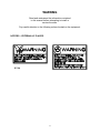
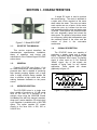
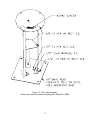
FEDERAL SIGNAL CORPORATION
8
Eclipse
&
NH
Eclipse
ELECTRO-MECHANICAL
DC POWER SIRENS
INSTALLATION AND OPERATING INSTRUCTIONS
Copyright 2005 Federal Signal Corporation
255368B1
04/06
IMPORTANT NOTICE
Federal Signal reserves the right to make changes to devices and
specifications detailed in the manual at any time in order to improve
reliability, function or design. The information in this book has been
carefully checked and is believed to be accurate; however, no
responsibility is assumed for any inaccuracies.
i
SAFETY NOTICES
People’s lives depend on your selection of suitable equipment and installation sites and your
safe installation, service, and operation of our products. Federal Signal recommends the following
publications from the Federal Emergency Management Agency for assistance with planning an
outdoor warning system: 1. The “Outdoor Warning Guide” (CPG 1-17), 2. “Civil Preparedness,
Principles of Warning” (CPG 1-14), 3. FEMA-REP-1, Appendix 3 (Nuclear Plant Guideline), and
4. FEMA-REP-10 (Nuclear Plant Guideline). Contact Federal Warning System’s Customer Care
Center at: http://www.federalwarningsystems.com or 1-800-524-3021 for further information
about these publications.
It is important to read, understand and follow all instructions shipped with this product. In addition,
listed below are some other important safety instructions and precautions you should follow.
PLANNING
•
If suitable warning equipment is not selected, the installation site for the siren is not selected
properly or the siren is not installed properly, it may not produce the intended optimum audible
warning. Follow Federal Emergency Management Agency (FEMA) recommendations.
•
If sirens are not activated in a timely manner when an emergency condition exists, they cannot
provide the intended audible warning. It is imperative that knowledgeable people, who are
provided with the necessary information, are available at all times to authorize the activation of
the sirens.
•
When sirens are used out of doors, people indoors may not be able to hear the warning
signals. Separate warning devices or procedures may be needed to effectively warn people
indoors.
•
The sound output of sirens is capable of causing permanent hearing damage. To prevent
excessive exposure, carefully plan siren placement, post warnings, and restrict access to
areas near sirens.
•
Activating the sirens may not result in people taking the desired actions if those to be warned
are not properly trained about the meaning of siren sounds. Siren users should follow FEMA
recommendations and instruct those to be warned of correct actions to be taken.
•
A siren that doesn’t work won’t provide any warning. After installation, service, or
maintenance, test the siren system to confirm that it is operating properly. Test the system
regularly to confirm that it will be operational in an emergency.
•
If future service and operating personnel do not have these instructions to refer to, the siren
system may not provide the intended audible warning and service personnel may be exposed
to death, permanent hearing loss, or other bodily injury. File these instructions in a safe place
and refer to them periodically. Give a copy of these instructions to new recruits and trainees.
Also, give a copy to anyone who is going to service or repair the siren.
ii
SAFETY NOTICES
People’s lives depend on your safe installation, service and operation of our products. It is
important to read, understand and follow all instructions shipped with this product. In addition,
listed below are some other important safety instructions and precautions you should follow:
INSTALLATION & SERVICE
•
Electrocution or severe personal injury can occur when performing various installation and
service functions such as making electrical connections, drilling holes, or lifting equipment.
Therefore experienced electricians in accordance with national, state and any other electrical
codes having jurisdiction should perform installation. All work should be performed under the
direction of the installation or service crew safety foreman.
•
The sound output of sirens is capable of causing permanent hearing damage. To prevent
excessive exposure, carefully plan siren placement, post warnings and restrict access to areas
near the sirens. Sirens may be operated from remote control points. Whenever possible,
disconnect all siren power including batteries before working near the siren.
•
After installation or service, test the siren system to confirm that it is operating properly. Test
the system regularly to confirm that it will be operational in an emergency.
•
If future service personnel do not have these warnings and all other instructions shipped with
the equipment to refer to, the siren system may not provide the intended audible warning and
service personnel may be exposed to death, permanent hearing loss, or other bodily injury.
File these instructions in a safe place and refer to them periodically. Give a copy of these
instructions to new recruits and trainees. Also, give a copy to anyone who is going to service
or repair the sirens. For additional copies, call the Federal Warning Systems Customer Care
Center at 800-524-3021 or write to them at 2645 Federal Signal Drive, University Park, IL
60466.
OPERATION
•
Failure to understand the capabilities and limitations of your siren system could result in
permanent hearing loss, other serious injuries or death to persons too close to the sirens when
you activate them or to those you need to warn. Carefully read and thoroughly understand all
safety notices in this manual and all operations-related-items in all instruction manuals shipped
with equipment. Thoroughly discuss all contingency plans with those responsible for warning
people in your community, company, or jurisdiction.
iii
Limited Warranty
The Signal Division, Federal Signal Corporation, warrants each new product to be
free from defects in material and workmanship, under normal use and service, for a
period of two years on parts replacement and bench labor (one year for Informer, EAS,
and Federal software products) from the date of delivery to the first user-purchaser.
Federal Warning Systems warrants every 2001 and Eclipse series Siren (Top of pole
only) to be free from defects in material, per our standard warranty, under normal use
and service for a period of five years on parts replacement.
During this warranty period, the obligation of Federal is limited to repairing or
replacing, as Federal may elect, any part or parts of such product which after
examination by Federal discloses to be defective in material and/or workmanship.
Federal will provide warranty for any unit which is delivered, transported prepaid, to
the Federal factory or designated authorized warranty service center for examination
and such examination reveals a defect in material and/or workmanship.
This warranty does not cover travel expenses, the cost of specialized equipment for
gaining access to the product, or labor changes for removal and re-installation of the
product. The Federal Signal Corporation warranty shall not apply to components or
accessories that have a separate warranty by the original manufacturer, such as, but
not limited to, batteries.
This warranty does not extend to any unit which has been subjected to abuse, misuse,
improper installation or which has been inadequately maintained, nor to units which
have problems related to service or modification at any facility other than Federal
factory or authorized warranty service centers. Moreover, Federal shall have no
liability with respect to defects arising in Products through any cause other than
ordinary use (such as, for example, accident, fire, lightning, water damage, or other
remaining acts of God).
THERE ARE NO OTHER WARRANTIES, EXPRESSED OR IMPLIED, INCLUDING
BUT NOT LIMITED TO, ANY IMPLIED WARRANTIES OF MERCHANTABILITY OR
FITNESS FOR A PARTICULAR PURPOSE. IN NO EVENT SHALL FEDERAL BE
LIABLE FOR ANY LOSS OF PROFITS OR ANY INDIRECT OR CONSEQUENTIAL
DAMAGES ARISING OUT OF ANY SUCH DEFECT IN MATERIAL WORKMANSHIP.
2645 Federal Signal Drive, University Park, IL 60466
Phone: (800) 524-3021 Fax: (708) 534-4865
Website: http://www.federalwarningsystems.com
iv
WARNING
Read and understand the information contained
in this manual before attempting to install or
service the siren.
Pay careful attention to the following notices located on the equipment.
NOTICES – EXTERNALLY PLACED.
v
TABLE OF CONTENTS
Section
Page
TABLE OF CONTENTS ..................................................................................................... vi
TABLE OF FIGURES......................................................................................................... vi
SECTION I - CHARACTERISTICS .....................................................................................1
1-1.
SCOPE OF THIS MANUAL. ................................................................................1
1-2.
GENERAL. ..........................................................................................................1
1-3.
SIREN DESCRIPTION. .......................................................................................1
1-4.
SIGNAL DESCRIPTION. .....................................................................................1
SECTION II - SPECIFICATIONS ........................................................................................2
SECTION III - INSTALLATION ...........................................................................................3
3-1.
SIREN LOCATION. .............................................................................................3
3-2.
SIREN INSTALLATION. ......................................................................................4
3-3.
PRE-OPERATION CHECKOUT AND MAINTENANCE PROCEDURE.............11
SECTION IV - SERVICE...................................................................................................12
4-1.
GENERAL INFORMATION. ..............................................................................12
TABLE OF FIGURES
Figure
Page
Figure 1-1. Model ECLIPSE8 .............................................................................................. 1
Figure 1-2. Signal Characteristics. ...................................................................................... 1
Figure 3-1. Siren Leg Assembly.......................................................................................... 5
Figure 3-2. Typical Pole-mounted Installation ..................................................................... 6
Figure 3-3. Conduit Connection Detail ................................................................................ 7
Figure 3-4. Typical Surface-mounted Siren Installation ...................................................... 9
Figure 3-5. Weight Distribution Mat Construction.............................................................. 10
Figure 4-1 Eclipse8 Parts List ........................................................................................... 13
Figure 4-2 EclipseNH Parts List ........................................................................................ 14
vi
SECTION I - CHARACTERISTICS
A single DC motor is used to produce
the sound energy. The motor is attached to
a stator with a rotor mounted on the motor
shaft inside the stator. The rotor and stator
each contain one row of ports. As the motor
rotates the rotor, air is drawn into the rotor
and passes through the rotor and stator ports
in pulses. These pulses are produced when
the rotor alternately opens and closes the
stator ports. The pulses of air produce sound
at a frequency (pitch) that is dependent upon
the rotational speed of the motor and the
number of ports in the rotor-stator
combination.
Figure 1-1. Model ECLIPSE8
1-1.
SCOPE OF THIS MANUAL.
1-4.
This service manual describes the
characteristics, specifications, installation,
theory of operation, and service and
maintenance of the Federal Signal ECLIPSE
series sirens.
1-2.
The ECLIPSE sirens are capable of
producing a steady signal and a wailing
signal. The steady signal is frequently used
as a Civil Defense “Alert” signal. The wailing
signal is often used as a Civil Defense
“Attack” signal. Any of the signals are
capable of being used for any desired
application. These signals are shown
graphically in figure 1-2.
GENERAL.
Federal’s ECLIPSE siren (figure 1-1) is
an electro-mechanical omni-directional, DC
powered siren that is capable of producing
high intensity warning signals over a large
area. A highly efficient design enables the
siren to produce a high sound level, while
making moderate demands on the power
source.
1-3.
SIGNAL DESCRIPTION.
SIREN DESCRIPTION.
The ECLIPSE8 siren is a single tone
siren capable of producing a 115 dB sound
level at 100 feet for a minimum of 15
minutes, when using the 2001DCB Control
Unit/Battery Box with fully charged, standard,
deep-cycle, marine batteries. 30-minute duty
cycle operation is available with a 2001TRB
option. This option supplies DC current
directly to the siren from a 208, 220 or
240VAC line.
Figure 1-2. Signal Characteristics.
1
SECTION II - SPECIFICATIONS
Power Requirements: ................................................... 46 VDC (or full wave
rectified AC) 112 amps. (nom.)
Wiring: .......................................................................... 2 AWG min.
Motor Type:................................................................... Series Wound DC 7Hp
Signal Information:
Signal
Frequency Range
Sweep Rate
STEADY
WAIL
FAST WAIL
525Hz
500 – 330 Hz
490 – 400 Hz
N.A.
10 sec.
4 sec.
Signal Duration............................................. 3 min. (programmable)
ECLIPSE8 Sound Output (SPL). .............................. 115 dBc max. (on axis) at 100' (30.5m)
ECLIPSENH (no horns) Sound Output ...................... 107 dBc max. (on axis) at 100' (30.5m)
Eclipse8 Dimensions (Height/Diameter) ................... 63" / 46.81" (Including stand)
160cm / 119 cm
EclipseNH Dimensions (Height/Diameter) ................. 63" / 23.63" (Including stand)
160cm / 60cm
ECLIPSE8
Siren Weight ..................................... 255 pounds (116 kg.)
Shipping Weight ............................... 380 pounds (173 kg.)
ECLIPSENH
Siren Weight ..................................... 175 pounds (80 kg.)
Shipping Weight ............................... 300 pounds (136 kg.)
Material .................................................................... Aluminum w/Stainless Steel Hardware
Operating Temperature............................................ -30°C to +60ºC
2
SECTION III - INSTALLATION
DANGER
Electrocution or severe personal injury can occur when making electrical connections,
drilling holes, or lifting equipment. Therefore, installation should be performed by
experienced electricians in accordance with national and local electrical codes.
3-1.
SIREN LOCATION.
The information in this section provides guidelines to aid the user in the selection of an
installation site that makes the best possible use of the siren.
WARNING
The output level of a ECLIPSE siren is capable of causing permanent hearing damage.
To prevent excessive exposure, carefully plan placement of siren and post warnings.
If the siren is being installed as part of a Community Warning system, ALWAYS follow
Federal Emergency Management Agency (FEMA) recommendations.
Careful consideration of the factors affecting the propagation of sound from the siren and the
response of the human ear to the sound will optimize the ability of the siren to effectively warn the
community.
The reduction of signal intensity as the distance from the siren increases and the minimum
desired signal level at the fringe of the area to be covered are important considerations when
choosing a siren installation site. As the distance from the siren increases, sound level losses
accumulate. These losses are a result of weather conditions, the terrain, obstructions in the sound
path, the pitch of the sound and the height of the siren.
Optimum sound propagation conditions exist when there are no obstructions in the sound
path, the terrain is flat, and the air is calm. Under these conditions, each time the distance from the
siren is doubled, the sound level decreases by approximately 10 dB.
Assuming a 10 dB loss per distance doubled and a 70dB minimum sound level, the effective
range of the ECLIPSE8 siren is approximately 1840 feet and the ECLIPSENH is 1300 feet.
A loss per distance doubled of 10 dB may be experienced because buildings and other
obstructions are frequently present in the sound path. In addition, the atmosphere is rarely calm,
and the terrain may not be flat. As a result, a typical loss per distance doubled in residential areas
may be 10dB, and as high as 12dB or more in areas having tall buildings or other factors
detrimental to sound propagation.
Experience indicates an individual with normal hearing will probably hear a warning signal
whose intensity is at least as high as the ambient noise level. But, to ensure adequate warning,
the warning signal should be at least 10 dB above ambient.
3
Experience has also shown that the ambient noise level in industrial districts is typically 90dB.
Therefore, for a person to hear a warning signal in an industrial area, the sound level intensity of
that signal must be approximately 100dB.
In business districts, an ambient noise level of 80dB is common and in residential areas, 68dB
of ambient noise is typical.
Wind speed and direction often affect the propagation of sound from the siren. Consequently,
the direction of the prevailing wind should also be a factor to consider when selecting the
installation site(s). For example, if the prevailing wind is from the west, it may be desirable to
install the siren toward the western edge of the area to be covered.
Other factors to consider before selecting the installation site include the availability of
electrical power, the ease of installation and maintenance, the height of surrounding obstructions,
and security against vandalism.
3-2.
SIREN INSTALLATION.
A. General.
Most siren installations are one of two types: Pole Mount or Flat Surface Mount. These two
configurations make it possible to install a siren in almost any situation. If the installations in this
paragraph are not suitable, modification of one of the configurations may be practical.
WARNING
An Eclipse siren must be installed at least 40 ft. above the ground to ensure sound levels on the
ground do not exceed safe levels.
Do not place fingers into any siren openings.
1. Uncrate the siren and remove the nuts that hold the siren on the shipping base. Lift the siren
approximately 3-1/2 ft. with a crane or hoist using the two eyehooks on the siren.
2. Install the siren legs to the siren using the four 3/8”-16 bolts and lock washers.
B. Pole Mounting.
A typical siren pole-mounted installation is shown in figure 3-2. The siren is mounted on a
Class 2 utility pole at least 40 ft. above the ground. It is attached to the pole by means of legs, as
shown in figure 3-1.
4
Figure 3-1. Siren Leg Assembly.
(Shown with optional surface mounting plate, Model No. RME)
5
ECLIPSE 8
CRANE LIFT EYEBOLTS
GROUND WIRE DETAIL
INSTALL GALVINIZED SHIMS, IF NEEDED,
BETWEEN ANGLE LEGS AND POLE
SIREN HEAD GROUND WIRE
SIREN ASSEMBLY GROUND WIRE
COMPRESSION CONNECTORS
OR CAD WELD JOINTS & TERMINALS
MINIMUM 50' CLASS 2 WOOD POLE
ALL CONDUIT & FITTINGS
RIGID ALUMINUM SEAL
W/ ANTI-OXIDANT
GROUND WIRE CONNECTIONS
• COMPRESSION FITTINGS OR CAD
WELDS MUST BE USED FOR ALL
WIRE CONNECTIONS
• COPPER COMPRESSION TERMINALS
MUST BE USED FOR BONDING
TO EQUIPMENT
• ALL JOINTS & CONNECTIONS MUST
BE TREATED W/ ANTI-OXIDANT
ANTENNA & BRACKET
(SEE DETAIL DWG# 291332A)
ANTENNA GROUND
AC SERVICE ENTRANCE
(CUSTOMER SUPPLIED)
1-1/4" CRANE LIFT HOLE
OPTIONAL AC TRANSFORMER
AND DC RECTIFIER
CONTROLLER CABINET
AC TRANSFORMER
AND RECTIFIER GROUND
(AS NEEDED)
50' 26'
(TYP.)
ELECTRICAL SERVICE
GROUND
BATTERY CABINET
(4 BATTERIES)
CABINET MOUNTING CHANNEL GROUND
SERVICE DISCONNECT
(CUSTOMER SUPPLIED)
MINIMUM #2 AWG BARE 19
STRAND GROUND WIRE
4-7 FT. TYP.
MINIMUM 2-5/8" X 10'
COPPERCLAD GROUND RODS
10'
FIRST GROUND ROD SHOULD BE IN UNDISTUBED
SOIL~3' FROM POLE, SECOND GROUND ROD SHOULD BE
APPROXIMATELY 20' AWAY FROM FIRST GROUND ROD,
IF CONDITIONS ALLOW
RECOMENDED INSTALL OF POLES
IN 30" X 10' HOLE; BACKFILL
W/ CRUSHED AGGREGATE
1/2" MINIMUM
Figure 3-2. Typical Pole-mounted Installation
6
Figure 3-3. Conduit Connection and Wiring Detail
7
WARNING
The lifting eyebolts do NOT have sufficient strength to support the combined weight of the
siren and a utility pole. Therefore, do NOT attempt to erect the pole and siren together
using the bracket as a lifting point.
Using the 3 ft. long angle iron legs, the siren is mounted on the Class 2 utility pole as follows:
1. Erect the utility pole in accordance with accepted practices. Be sure the pole extends at
least 40 ft. above the ground (refer to WARNING above).
2. Raise the siren to the necessary height, and lower it over the pole.
3. Adjust the legs and insert shims, if necessary, between the siren legs and pole. Bolt the
siren to the pole using two 5/8" lag bolts, at least four inches long for each leg. Tighten all
bolts.
4. Install the siren grounding as shown in figure 3-2.
5. Refer to Figure 3-3 for running conduit to the siren and follow the instructions provided with
the siren controller for making electrical connections – omitting any references to rotation.
C. Flat Surface Mount.
Note: A qualified Professional Engineer should approve mounting locations, materials and
methods prior to installation.
A model RME mounting plate is required for mounting on flat surfaces such as a building or
top plate of a steel or concrete pole. This installation configuration is practical for buildings that
have a flat roof. The siren can be anchored directly to the roof, on a platform as shown in figure 34, or on a weight distribution mat like the one shown in figure 3-5.
A mat is required when the siren mounting surface is unable to support at least 280 pounds
(127kg.) over a 1.5 square foot area. The mat shown in figure 3-5 distributes the siren weight over
an 8 square foot area. When installing the siren on a flat roof, be sure that it clears the parapets
or other obstructions by at least ten feet.
To install a ECLIPSE on a flat roof or other flat surface, proceed as follows:
1. If required, construct a platform for mounting the siren, which must be capable of
supporting at least 300lbs. (660kg.) as well as withstanding a siren wind load of 110 mph. The
platform must also be capable of distributing its own weight plus the siren to a value that is safe for
the mounting surface. Platform design and construction details are left to the installer. Locate the
platform at the siren installation site. Using suitable hardware (not supplied), anchor the platform to
the mounting surface.
8
Figure 3-4. Typical Surface-mounted Siren Installation
9
WARNING
The siren’s lifting eyebolts do not have sufficient strength to support the combined weight
of the siren and a mounting platform. Therefore, do NOT lift the siren and platform
together using the siren’s eyebolts as the lifting points.
2. Hoist the siren to the installation site using the two eyebolts as a lifting point (refer to
WARNING above).
3. Anchor the siren to the mounting surface with 1/2" lag bolts or nuts and bolts, as
appropriate through the mounting holes (one in each corner) in the siren base plate (see
figure 3-4, detail A). If the siren is mounted directly on a roof, (without a platform or weight
distribution mat) be sure to install waterproof joints at the points where the mounting bolts
pass through the roof so that water does not enter the building.
4. Refer to Figure 3-3 for running conduit to the siren and follow the instructions provided with
the siren controller for making electrical connections – omitting any references to rotation.
Figure 3-5. Weight Distribution Mat Construction
10
3-3.
PRE-OPERATION CHECKOUT AND MAINTENANCE PROCEDURE
After the siren has been completely installed, perform the following checks before putting the
siren into service. This procedure is also recommended as a maintenance procedure.
WARNING
The output sound level of a siren is capable of causing severe hearing discomfort or
permanent hearing damage. Therefore, ALWAYS wear hearing protection when
performing tests or maintenance on the siren.
A.
Make sure that all air intakes and sound outlets are not obstructed.
B.
Make sure all connections in the Control Unit/Battery Box (if applicable) are correct and
properly tightened.
C. Ensure the mounting structure is secure and all siren hardware properly attached and
secure.
D. Ensure all people and animals are at least 40’ away from the siren in every direction to
avoid hearing damage.
E.
Activate a siren function at the control panel and check for proper sound output.
F.
After the installation is complete and it has been established that the siren is operating
properly, Federal recommends that all control devices be padlocked to discourage
tampering and vandalism.
G. Test the ECLIPSE siren for proper operation at least once a month. A daily test at noon,
curfew, or other selected time is preferred. This not only enhances the usefulness of the
siren, but instills public confidence in the reliability of the warning system.
H. In order to minimize the possibility of siren failure, annual inspection is desirable. If
applicable, battery replacement should be performed approximately every 3-5 years. This
schedule is only a suggested guideline. It may be necessary to vary the schedule if the
siren is used frequently or if it is used in an extreme climate.
11
SECTION IV - SERVICE
4-1.
GENERAL INFORMATION.
DANGER
Service should be performed by qualified personnel familiar with the siren, associated
controls, and power sources being used. The siren has moving parts, high operating
currents, and may have explosive gases and corrosive materials that could cause severe
personal injury, electrocution, or death. Before servicing or maintaining, ensure that
remote activation can not occur and disconnect power to the siren and its controls.
WARNING
The output level of a ECLIPSE siren is capable of causing permanent hearing damage.
Therefore, ALWAYS wear hearing protection when performing tests or maintenance on
the siren.
Experience has shown that all Federal sirens are highly reliable devices. However, if a siren failure
does occur, Federal will provide technical assistance with problems that cannot be handled
satisfactorily and promptly locally. If assistance is desired, contact:
FWS Customer Care Center
Signal Division
Federal Signal Corporation
2645 Federal Signal Drive
University Park, Illinois 60466
800-524-3021
Refer to figures 4-1 and 4-2 for a complete siren parts lists.
12
Figure 4-1 Eclipse8 Parts List
13
Figure 4-2 EclipseNH Parts List
14