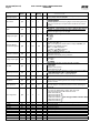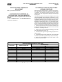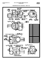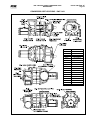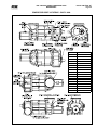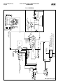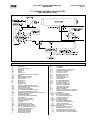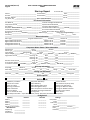
1
Form 070.610-IOM (NOV 2014) INSTALLATION - OPERATION - MAINTENANCE File: Replaces: Dist: SERVICE MANUAL - Section 70 070.610-IOM (AUG 2014) 3, 3a, 3b, 3c RWF II ROTARY SCREW COMPRESSOR UNITS ALL REFRIGERANTS MODELS 100 through 1080 THIS MANUAL CONTAINS RIGGING, ASSEMBLY, START-UP, AND MAINTENANCE INSTRUCTIONS. READ THOROUGHLY BEFORE BEGINNING INSTALLATION. FAILURE TO FOLLOW THESE INSTRUCTIONS MAY RESULT IN PERSONAL INJURY OR DEATH, DAMAGE TO THE UNIT, OR IMPROPER OPERATION. Please check www.jci.com/frick for the latest version of this publication. 070.610-IOM (NOV 14) Page 2 RWF II ROTARY SCREW COMPRESSOR UNITS INSTALLATION - OPERATION - MAINTENANCE Contents General Information Maintenance Preface............................................................................... 3 Design Limitations.............................................................. 3 Job Inspection.................................................................... 3 Transit Damage Claims....................................................... 3 Unit Identification............................................................... 3 Compressor Identification.................................................. 4 General Information......................................................... 25 Normal Maintenance Operations...................................... 25 General maintenance....................................................... 25 Compressor Shutdown And Start-Up............................... 25 General Instructions For Replacing. Compressor Unit Components.................................. 25 Oil Filter (OF‑1) Cartridge Style....................................... 26 Strainer – Demand Oil Pump........................................... 27 Strainer – Liquid Injection................................................ 27 Coalescer Filter Element(s)............................................... 27 Changing Oil..................................................................... 27 Demand Pump Disassembly............................................. 28 Demand Pump Assembly.................................................. 29 Thrust Bearing Adjustment.............................................. 30 Installation Of Carbon Graphite Bushings......................... 30 Troubleshooting The Demand Pump................................ 30 Preventive Maintenance................................................... 31 Maintenance Schedule..................................................... 32 Recommended Maintenance Program.............................. 32 Vibration Analysis............................................................ 32 Oil Quality And Analysis................................................... 33 Oil Sampling Procedure.................................................... 33 Operating Log.................................................................. 33 Motor Bearings................................................................ 33 Grease Compatibility........................................................ 34 Troubleshooting Guide..................................................... 34 Abnormal Operation Analysis And Correction.................. 34 Servicing The Cold-Start Valve........................................ 35 Pressure Transducers – Testing........................................ 36 Pressure Transducers – Replacement............................... 36 Capacity Linear Transmitter – Slide Valve........................ 37 Volume Ratio Control Transmitter – Slide Stop................ 37 Temperature Sensor......................................................... 38 Oil Level Transmitter........................................................ 38 Troubleshooting the RWF II Compressor.......................... 39 Troubleshooting The Demand Pump System.................... 39 Troubleshooting The Oil Separation System.................... 40 Troubleshooting The Hydraulic System............................ 40 Motor And Bare Compressor Replacement...................... 41 Shutdown Due To Improper Oil Pressure . (High Stage And Booster)......................................... 41 SAE Straight Thread O-Ring Fittings . Assembly Procedure................................................. 41 Compressor Port Locations.............................................. 42 P & I Diagram................................................................... 50 Installation Foundation......................................................................... 5 Rigging And Handling......................................................... 5 Skid Removal..................................................................... 5 Checking Motor/Compressor Rotation............................... 6 Compressor/Motor Coupling Installation............................ 6 Oil Pump Coupling.............................................................. 7 Holding Charge And Storage.............................................. 7 Oil Charge.......................................................................... 7 Oil Heater(s)....................................................................... 8 Oil Filter(s)......................................................................... 8 Suction Valve Mounting..................................................... 8 Thermosyphon Oil Cooling................................................. 8 Liquid Injection Oil Cooling (Optional)................................ 9 Water-Cooled Oil Cooling (Optional)................................ 10 Economizer – High Stage (Optional)................................ 10 Economizer Load Balancing.............................................. 11 Electrical.......................................................................... 12 Motor Starter Package..................................................... 12 Current Transformer (CT) Ratios...................................... 13 Minimum Burden Ratings................................................. 14 Control Power Regulator.................................................. 14 Operation Operation And Startup Instructions.................................. 15 SGC Compressor.............................................................. 15 Compressor Lubrication System....................................... 15 No Pump Oil System........................................................ 15 Demand Pump Oil System................................................ 16 Compressor Oil Separation System.................................. 16 Cold-Start System............................................................ 16 Compressor Hydraulic System.......................................... 17 Volume Ratio Control....................................................... 17 Compressor Oil Cooling Systems..................................... 17 Single-Port Liquid Injection.............................................. 18 Dual-Port Liquid Injection................................................ 18 Quantum™HD EZ-COOL™ Liquid Injection Adjustment Procedure................................................................. 19 Operation Of Danfoss Liquid Injection Valve.................... 20 Suction Check Valve Bypass............................................. 23 Low Ambient Operation................................................... 23 Suction Check Valve Power Assist Kit.............................. 23 Balance Piston Pressure Regulator................................... 23 Initial Start-Up................................................................. 24 Initial Start-Up Procedure................................................ 24 Normal Start-Up Procedure............................................. 24 VFD Skip Frequencies...................................................... 24 Installation Of Electronic Equipment Wire Sizing....................................................................... 53 Voltage Source................................................................. 53 Grounding........................................................................ 54 VFD Applications.............................................................. 54 Conduit............................................................................ 55 Wiring Practices............................................................... 55 Communications.............................................................. 57 UPS Power and Quantum™HD Panels............................... 57 Forms Operating Log Sheet........................................................ 58 RWF II Compressor Prestart Checklist.............................. 59 Vibration Data Sheet........................................................ 64 INDEX............................................................................... 65 RWF II ROTARY SCREW COMPRESSOR UNITS GENERAL INFORMATION General Information Preface This manual has been prepared to acquaint the owner and serviceman with the INSTALLATION, OPERATION, and MAIN TENANCE procedures as recommended by Johnson Controls for Frick® RWF II Rotary Screw Compressor Units. For information about the functions of the Quantum™HD control panels, communications, specifications, and wiring diagrams, see publication series 090.040-O, 090.040-M, 090.040-CS, and 090.040-SPC. It is most important that these units be properly applied to an adequately controlled refrigeration system. Your authorized Frick® representative should be consulted for their expert guidance in this determination. Proper performance and continued satisfaction with these units is dependent upon: CORRECT INSTALLATION PROPER OPERATION REGULAR, SYSTEMATIC MAINTENANCE To ensure correct installation and application, the equipment must be properly selected and connected to a properly de signed and installed system. The Engineering plans, piping layouts, etc. must be detailed in accordance with the best practices and local codes, such as those outlined in ASHRAE literature. 070.610-IOM (NOV 14) Page 3 Job Inspection Immediately upon delivery examine all crates, boxes and exposed compressor and component surfaces for damage. Unpack all items and check against shipping lists for any discrepancy. Examine all items for damage in transit. Transit Damage Claims All claims must be made by consignee. This is an ICC re quirement. Request immediate inspection by the agent of the carrier and be sure the proper claim forms are executed. Report damage or shortage claims immediately to Johnson Controls Inc., Frick® Sales Administration Department, in Waynesboro, PA. Unit Identification Each compressor unit has 2 identification data plates. The compressor data plate containing compressor model and serial number is mounted on the compressor body. The unit data plate containing unit model, serial number and Frick® sales order number is mounted on the side of the Quantum™HD control panel. NOTICE When inquiring about the compressor or unit, or ordering repair parts, provide the MODEL, SERIAL, and FRICK® SALES ORDER NUMBERS from these data plates. A refrigeration compressor is a VAPOR PUMP. To be certain that it is not being subjected to liquid refrigerant carryover it is necessary that refrigerant controls are carefully selected and in good operating condition; the piping is properly sized and traps, if necessary, are correctly arranged; the suction line has an accumulator or slugging protection; that load surges are known and provisions made for control; operating cycles and defrosting periods are reasonable; and that high side condensers are sized within system and compressor design limits. It is recommended that the entering vapor temperature to the compressor be superheated to 10°F above the refrigerant saturation temperature. This assures that all refrigerant at the compressor suction is in the vapor state. Design Limitations The compressor units are designed for operation within the pressure and temperature limits as shown in Frick® publica tion 070.610-SED. UNIT DATA PLATE SAFETY PRECAUTION DEFINITIONS WARNING Indicates an imminently hazardous situation which, if not avoided, will result in death or serious injury. Indicates a potentially hazardous situation or practice which, if not avoided, will result in death or serious injury. CAUTION Indicates a potentially hazardous situation or practice which, if not avoided, will result in damage to equipment and/or minor injury. DANGER NOTICE Indicates an operating procedure, practice, etc., or portion thereof which is essential to highlight. 070.610-IOM (NOV 14) Page 4 RWF II ROTARY SCREW COMPRESSOR UNITS GENERAL INFORMATION Compressor Identification Each compressor has an identification data plate (see below), containing compressor model and serial number mounted on the compressor body. COMPRESSOR DATA PLATE Rotary screw compressor serial numbers are defined by the following information: EXAMPLE: 10240A90000015Z GLOBAL ADDITIONAL PLANT DECADE MONTH YEAR SEQ NO. REMARKS 1024 0 A 9 0000015 Z Month: A = JAN, B = FEB, C = MAR, D = APR, E = MAY, F = JUN, G = JUL, H = AUG, K = SEP, L = OCT, M = NOV, N = DEC. Additional Remarks: R = Remanufactured; Z = Deviation from Standard Configuration. Geometrical swept volume Rotor Compressor Diameter Rotor Model mm L/D SGC1913 193 1.35 SGC 1918 193 1.8 SGC 2313 233 1.35 SGC 2317 233 1.7 SGC 2321 233 2.1 SGC 2813 283 1.35 SGC 2817 283 1.7 SGC 2821 283 2.1 SGC 2824 283 2.4 SGCH/B 3511 355 1.1 SGCH/B 3515 355 1.5 SGCH/B 3519 355 1.9 SGCB 3524 355 2.4 Table 1. Geometrical Swept Volume Max Speed Rpm 4,500 4,500 4,500 4,500 4,500 4,200 4,200 4,200 4,200 4,200 4,200 4,200 4,200 Geometrical Swept Volume Drive Shaft End ft³/ Rev m³/Rev 0.16653 0.004713 0.22204 0.006284 0.29301 0.008292 0.36897 0.010442 0.45580 0.012899 0.52501 0.014858 0.66115 0.018711 0.79546 0.022512 0.89858 0.025430 0.82248 0.023276 1.12154 0.031739 1.42748 0.040398 1.80328 0.051033 Cfm 3550 Rpm 591 788 1,040 1,310 1,618 1,864 2,347 2,824 3,190 2,920 3,981 5,068 6,402 m³/h 2950 Rpm 834 1,112 1,468 1,848 2,283 2,630 3,312 3,985 4,501 4,120 5,618 7,150 9,033 RWF II ROTARY SCREW COMPRESSOR UNITS INSTALLATION Installation if disconnected from the compressor. See Allowable Flange Loads table. Foundation If RWF II Rotary Screw Compressor Unit is shipped mounted on a wood skid, it must be removed prior to unit installation. WARNING Allow space for servicing the unit per factory drawings. The first requirement of the compressor foundation is that it must be able to support the weight of the compressor package including coolers, oil, and refrigerant charge. Screw compressors are capable of converting large quantities of shaft power into gas compression in a relatively small space and a mass is required to effectively dampen these relatively high-frequency vibrations. Firmly anchoring the compressor package to a suitable foundation by proper application of grout and elimination of piping stress imposed on the compressor is the best insur ance for a trouble-free installation. Use only the certified general arrangement drawings from Frick to determine the mounting foot locations and to allow for recommended clear ances around the unit for ease of operation and servicing. Foundations must be in compliance with local building codes and materials should be of industrial quality. The floor must be a minimum of 6 inches of reinforced con crete and housekeeping pads are recommended. Anchor bolts are required to firmly tie the unit to the floor. Once the unit is rigged into place (See RIGGING and HANDLING), the feet must then be shimmed in order to level the unit. The shims should be placed to position the feet roughly one inch above the housekeeping pad to allow room for grouting. An expansion-type epoxy grout must be worked under all areas of the base with no voids and be allowed to settle with a slight outward slope so oil and water can run off of the base. When installing on a steel base, the following guidelines should be implemented to properly design the system base: 1. Use I-beams in the skid where the screw compressor will be attached to the system base. They should run parallel to the package feet and support the feet for their full length. 2. The compressor unit feet should be continuously welded to the system base at all points of contact. 3. The compressor unit should not be mounted on vibration isolators in order to hold down package vibration levels. 4. The customer’s foundation for the system base should fully support the system base under all areas, but most certainly under the I-beams that support the compressor package. When installing on the upper floors of buildings, extra precau tions should be taken to prevent normal package vibration from being transferred to the building structure. It may be necessary to use rubber or spring isolators, or a combination of both, to prevent the transmission of compressor vibration directly to the structure. However, this may increase package vibration levels because the compressor is not in contact with any damping mass. The mounting and support of suction and discharge lines is also very important. Rubber or spring pipe supports may be required to avoid exciting the build ing structure at any pipe supports close to the compressor package. It is best to employ a vibration expert in the design of a proper mounting arrangement. In any screw compressor installation, suction and discharge lines should be supported in pipe hangers (preferably within two feet of vertical pipe run) so that the lines won’t move 070.610-IOM (NOV 14) Page 5 NOZ. SIZE NPS 1 1.25 1.5 2 3 4 5 6 8 10 14 ALLOWABLE FLANGE LOADS MOMENTS (ft-lbf) LOAD (lbf) AXIAL VERT. LAT. AXIAL VERT. LAT. MC ML P VC VL MR 25 25 25 50 50 50 25 25 25 50 50 50 50 40 40 100 75 75 100 70 70 150 125 125 250 175 175 225 250 250 400 200 200 300 400 400 425 400 400 400 450 450 1,000 750 750 650 650 650 1,500 1,000 1,000 1,500 900 900 1,500 1,200 1,200 1,500 1,200 1,200 2,000 1,800 1,800 1,700 2,000 2,000 Table 2. Allowable Flange Loads Consult a licensed architect to determine the proper foun dation requirements for any large engine or turbine drive. When applying screw compressors at high pressures, the customer must be prepared for package vibration and noise higher than the values predicted for normal refrigeration duty. Proper foundations and proper installation methods are vital; and even then, sound attenuation or noise curtains may be required to reduce noise to desired levels. For more detailed information on Screw Compressor Foundations, please request Frick® publication 070.210-IB. Rigging And Handling WARNING This screw compressor package may be top-heavy. Use caution in rigging and handling. The unit can be moved with rigging, using a crane and spreader bar, by hooking into the four lifting eyes on the oil separator. If a motor is mounted, appropriate adjustment in the lifting point should be made to compensate for motor weight. Adjustment of the lifting point must also be made for any additions to the standard package such as an external oil cooler, etc., because the center of balance will be affected. Refer to supplied engineering drawings to determine the package center of gravity. The unit can be moved with a forklift by forking under the skid, or it can be skidded into place with pinch bars by push ing against the skid. NEVER MOVE THE UNIT BY PUSHING OR FORKING AGAINST THE SEPARATOR SHELL OR ITS MOUNTING SUPPORTS. Skid Removal If the unit is rigged into place, the skid can be removed by taking off the nuts and bolts that are fastening the unit mounting supports to the skid before lowering the unit onto the mounting surface. If the unit is skidded into place, remove the cross members from the skid and remove the nuts anchoring the unit to the skid. Using a 10-ton jack under the separator raise the unit at the compressor end until it clears the two mounting bolts. Spread the skid to clear the unit mounting support, then lower the unit to the surface. Repeat procedure on opposite end. 070.610-IOM (NOV 14) Page 6 RWF II ROTARY SCREW COMPRESSOR UNITS INSTALLATION Checking Motor/Compressor Rotation WARNING Make sure coupling hubs are tight-ened to the shaft before rotatingthe motor to prevent them from flying off and possibly causing serious injury or death. WARNING Injury may occur if loose clothing, etc, becomes entangled on the spinning motor shaft. BP COUPLING INSTALLATION PROCEDURE 1. Install the motor and compressor coupling hubs and keys on their respective shafts. Ensure that they can slide hori zontally so that once the disc packs are installed, no axial stress is transferred to the disc packs by a stuck coupling hub. Use no lubricants. 2. Rotate both hubs so that the keys are 180° opposed. With the hubs mounted and the axial spacing set, proceed to place the spacer between the two hub flanges. Care should be taken when handling the spacer. Be sure the spacer is fully supported at this time. Damage to the unitized flex discs may result after they have been installed if the spacer is not fully supported. COMPRESSOR ROTATION IS CLOCKWISE WHEN FACING THE END OF THE COMPRESSOR SHAFT. Under NO conditions should the motor rotation be checked with the coupling center installed as damage to the compressor may result. Bump the motor to check for correct compressor rotation. After verification, install disc drive spacer, as applicable. Install the unitized flex disc at this time. Start a bolt through a bolt hole in the spacer. Put the unitized flex disc between the hub and spacer until a bushing hole in the unitized flex disc lines up with the bolt. Slide the bolt through the bushing hole in the unitized flex disc. Install the locknut until it is snug. Make sure that all bolt threads are clean and lightly oiled. Do not torque any locknuts at this time. Now pivot the unitized flex disc until the other bushing holes in the flex disc are in line with the bolt holes in the spacer. Install the rest of the spacer bolts at this time. The remaining bolts for this end of the coupling can be installed through the hub bolt holes and flex disc bushing holes. Compressor/Motor Coupling Installation Install the unitized flex disc in the other end of the coupling. The unitized flex disc, as installed, should look flat and parallel with the mating hub and spacer flanges. The RWF II unit has compressor to motor alignment through the use of a machined cast iron tunnel. This tunnel is factory set through machining tolerances ensuring motor compres sor alignment. No alignment is required in the field. See Figure below. Torque the disc pack locknuts as recommended in the BP SERIES COUPLING DATA TABLE. The bolts should be held in place while the locknuts are torqued. 3. Center the coupling between the shafts. Ensure that the keys are fully engaged in their keyways. 4. Tighten the motor and compressor shaft clamping bolts evenly. Torque to the recommended specification in the BP coupling data table. 5. Torque the keyway setscrews as recommended in the BP SERIES COUPLING DATA TABLE. NOTICE Only after the shaft clamping bolts are tightened to their final torque can the keyway set screws be tightened. If the keyway set screws are tightened before the shaft clamping bolts are tightened, then the hubs can be cocked on the shaft. Figure 1. BP Coupling BP SERIES COUPLING DATA TABLE BP SERIES SIZE BP 38 BP 43 BP 48 BP 53 BP 58 BP 63 DISC PACK LOCKNUT TORQUE (Lube*) SIZE UNF FT-LB NM 17 23.1 5/16-24 40 54.2 7/16-20 40 54.2 7/16-20 60 81.4 1/2-20 120 162.7 5/8-18 120 162.7 5/8-18 Table 3. BP Series Coupling Data HUB CLAMPING BOLTS TORQUE SIZE UNF FT-LB NM 41 55.6 3/8-24 41 55.6 3/8-24 41 55.6 3/8-24 66 89.5 7/16-20 101 137.0 1/2-20 101 137.0 1/2-20 KEYWAY SETSCREW TORQUE SIZE NC FT-LB NM 22 29.8 3/8-16 22 29.8 3/8-16 53 71.9 1/2-13 53 71.9 1/2-13 53 71.9 1/2-13 186 252.2 3/4-10 RWF II ROTARY SCREW COMPRESSOR UNITS INSTALLATION CH SERIES COUPLING DATA TABLE Coupling Hub Keyway Setscrew Clamp Bolt Face CH Series Spacing Torque (Dry) Size Torque Size Size In. mm Ft-Lb Nm UNF Ft-Lb Nm UNC 9 55 74.6 ³\, -24 13 17.6 B\zn -18 1M\zn 36.5 10 17.6 B\zn -18 1ZZ\zn 42.9 130 176.3 ½ -20 13 11 17.6 B\zn -18 1M\, 47.6 130 176.3 ½ -20 13 Table 4. CH Series Coupling Data CH COUPLING INSTALLATION PROCEDURE The T.B. Woods Elastomeric Type CH Coupling is used in most applications. This coupling consists of two drive hubs and a gear-type Hytrel or EDPM and neoprene drive spacer. The split hub is clamped to the shaft by tightening the clamp screws. Torque is transmitted from the motor through the elastomeric gear which floats freely between the hubs. Be cause of the use of the motor/compressor adapter housing on the RWF II, no field alignment is necessary. 1. Inspect the shaft of the motor and compressor to ensure that no nicks, grease, or foreign matter is present. 2. Inspect the bores in the coupling hubs to make sure that they are free of burrs, dirt, and grit. 3. Check that the keys fit the hubs and shafts properly. 4. Slide one hub onto each shaft as far as possible. It may be necessary to use a screwdriver as a wedge in the slot to open the bore before the hubs will slide on the shafts. 5. Rotate both hubs so that the keys are 180° opposed. 6. Hold the elastomeric gear between the hubs and slide both hubs onto the gear to fully engage the mating teeth. Center the gear and hub assembly so there is equal engagement on both shafts. Please note that the hubs may overhang the ends of shafts. Adjust the Face Spacing between hubs as specified in the CH Coupling Data Table. Ensure that the keys are fully engaged in their keyways. 7. Torque the clamping bolts in both hubs to the torque value given in the CH SERIES COUPLING DATA TABLE. NOTICE DO NOT USE ANY LUBRICANT ON THESE BOLTS. 8. Torque the keyway setscrew in both hubs to the torque value given in the CH SERIES COUPLING DATA TABLE. NOTICE Only after the shaft clamping bolts are tightened to their final torque can the keyway set screws be tightened. If the keyway set screws are tightened before the shaft clamping bolts are tightened, then the hubs can be cocked on the shaft. Oil Pump Coupling Compressor units with direct motor/pump coupled pumps need no pump/motor coupling alignment since this is main tained by the close-coupled arrangement. 070.610-IOM (NOV 14) Page 7 Holding Charge And Storage Each RWF II compressor unit is pressure and leak tested at the factory and then thoroughly evacuated and charged with dry nitrogen to ensure the integrity of the unit during shipping and short term storage prior to installation. CAUTION Care must be taken when entering the unit to ensure that the nitrogen charge is safely released. WARNING Holding-charge shipping gauges on separator and external oil cooler are rated for 30 PSIG and are for checking the shipping charge only. They must be removed before pressure testing the system and before charging the system with refrigerant. Failure to remove these gauges may result in catastrophic failure of the gauge and uncontrolled release of refrigerant resulting in serious injury or death. All units must be kept in a clean, dry location to prevent corrosion damage. Reasonable consideration must be given to proper care for the solid-state components of the mi croprocessor. Please contact Frick® service for long term storage requirements. COMPRESSOR UNIT OIL WARNING DO NOT MIX OILS of different brands, manufacturers, or types. Mixing of oils may cause excessive oil foaming, nuisance oil level cutouts, oil pressure loss, gas or oil leakage and catastrophic compressor failure. NOTICE The Frick oil charge shipped with the unit is the best suited lubricant for the conditions specified at the time of purchase. If there is any doubt due to the refrigerant, operating pressures, or temperatures, refer to Frick Oil publication 160.802-SPC. Oil Charge The normal charging level is midway in the top sight glass located midway along the oil separator shell. Normal operating level is midway between the top sight glass and bottom sight glass. The table gives the approximate oil charge quantity. Add oil by attaching the end of a suitable pressure type hose to the oil drain valve located under the oil separator (see Figure 2). Using a pressuretype pump and the recom mended Frick® oil, open the drain valve and pump oil into the separator. RWF II MODEL NO. 100 134 177 222 270 316 399 480 496 546 676 856 1080 BASIC* CHARGE (gal.) 45 45 90 90 120 120 120 130 190 130 220 220 220 *Includes total in horizontal oil separator and piping. Add 5 gal. for oil cooler up to Model 270, 10 gal. for 316 - 1080. 070.610-IOM (NOV 14) Page 8 RWF II ROTARY SCREW COMPRESSOR UNITS INSTALLATION NOTICE Evacuation of the oil separator will assist the flow of oil into the unit. Also, fill slowly because oil will fill up in the separator faster than it shows in the sight glass. Suction Valve Mounting The suction isolation valve is shipped loose from the factory, so it can be installed at various positions within the suction line piping to the compressor. DO NOT install the valve at the compressor suction with flow against the cone/button (see Figure 3 - TOP). When the isolation valve is installed in this position, uneven flow is generated across the suction check valve which is mounted at the inlet to the compressor. This uneven flow causes the disks in the check valve to strike against the stop pin, and eventually damage the internals of the check valve. If the isolation valve is mounted at the compressor suction, DO INSTALL with flow across the cone/ button (see Figure 3 - BOTTOM). Please design your system piping accordingly. SEE CAUTION BELOW ! CAUTION After removing the suction sealing disc, confirm that the check valve hinge pin is in the vertical position! If the hinge pin is not in a vertical position, then failure of the check valve may occur. INCORRECT! Figure 2. Oil Drain Valve Oil distillers and similar equipment which act to trap oil must be filled prior to unit operation to normal design outlet levels. The same pump used to charge the unit may be used for filling these auxiliary oil reservoirs. NOTICE The sight glass located in the coalescing end of the separator near the discharge connection should remain empty. Oil Heater(s) Standard units are equipped with one to three 1000 watt oil heaters, providing sufficient heat to maintain the oil temperature for most indoor applications during shutdown cycles to permit safe start-up. Should additional heating capacity be required because of low ambient temperature, contact Johnson Controls-Frick . The heaters are energized only when the unit is not in operation. ® WARNING DO NOT ENERGIZE THE HEATERS when there is no oil in the unit, the heaters will burn out. The oil heaters will be energized whenever 120 volt control power is applied to the unit and the compressor is not running, unless the 16 amp circuit breaker in the micro enclosure is turned off. Oil Filter(s) NOTICE Use of filter elements other than Frick® may cause warranty claim to be denied. The oil filter(s) and coalescer element(s) shipped with the unit are best suited to ensure proper filtration and operation of the system. CORRECT! Figure 3. Valve Installation Thermosyphon Oil Cooling Thermosyphon oil cooling is an economical, effective method for cooling oil on screw compressor units. Thermosyphon cooling utilizes liquid refrigerant at condenser pressure and temperature that is partially vaporized at the condenser tem perature in a plate and shell vessel, cooling the oil to within 35°F of that temperature. The vapor, at condensing pressure, is vented to the condenser inlet and reliquified. This method is the most cost effective of all currently applied cooling systems since no compressor capacity is lost or compressor power penalties incurred. The vapor from the cooler need only be condensed, not compressed. Refrigerant flow to the cooler is automatic, driven by the thermosyphon principle and cooling flow increases as the oil inlet temperature rises. RWF II ROTARY SCREW COMPRESSOR UNITS INSTALLATION EQUIPMENT - The basic equipment required for a ther mosyphon system consists of: 1. A source of liquid refrigerant at condensing pressure and temperature, located in close proximity to the unit to mini mize piping pressure drop. The liquid level in the refrigerant source must be 6 to 8 feet minimum above the center of the oil cooler. 2. A plate and shell oil cooler with: Plate Side: Oil 400 psi design Shell Side: Refrigerant 400 psi design Due to the many variations in refrigeration system design and physical layout, several systems for assuring the above criteria are possible. 070.610-IOM (NOV 14) Page 9 1. The refrigerant source, thermosyphon or system receiver, should be in close proximity to the unit to minimize piping pressure drop. 2. The liquid level in the refrigerant source must be 6 to 8 feet minimum above the center of the oil cooler. 3. A safety valve should be installed if refrigerant isolation valves are used for the oil cooler. NOTICE The component and piping arrangement shown in Figure 5 is intended only to illustrate the operating principles of thermosyphon oil cooling. Other component layouts may be better suited to a specific installation. Refer to publication 070.900-E for additional information on Thermosyphon Oil Cooling. Figure 4. Thermosyphon Receiver System SYSTEM OPERATION - Liquid refrigerant fills the cooler shell side up to the Thermosyphon receiver liquid level. Hot oil (above the liquid temperature) flowing through the cooler will cause some of the refrigerant to boil and vapor ize. The vapor rises in the return line. The density of the refrigerant liquid/vapor mixture in the return line is consid erably less than the density of the liquid in the supply line. This imbalance provides a differential pressure that sustains a flow condition to the oil cooler. This relationship involves: 1. Liquid height above the cooler. 2. Oil heat of rejection. 3. Cooler size and piping pressure drops. Current thermosyphon systems are using two-pass oil coolers and flow rates based on 3:1 overfeed. The liquid/vapor returned from the cooler is separated in the receiver. The vapor is vented to the condenser inlet and need only be reliquified since it is still at condenser pressure (Figure 4). OIL TEMPERATURE CONTROL - Oil temperature will gen erally run about 15 - 35°F above condensing temperature. In many cases, an oil temperature control is not required if condensing temperature is above 65°F as oil temperature can be allowed to float with condenser temperature. Condensing Temperature: Oil Temperature: 65°F - 105°F 80°F - 140°F INSTALLATION - The plate-and-shell type thermosyphon oil cooler with oil-side piping and a thermostatically controlled mixing valve are factory mounted and piped. The customer must supply and install all piping and equipment located outside of the shaded area on the piping diagram with con sideration given to the following: Figure 5. TSOC Piping Arrangement 1. The thermosyphon oil cooler is supplied with oil side piped to the compressor unit and stub ends supplied on the refrigerant side. 2. A refrigerant-side safety valve is required in this location only when refrigerant isolation valves are installed between the cooler and thermosyphon receiver. If no valves are used between the cooler and TSOC receiver, the safety valve on the TSOC receiver must be sized to handle the volume of both vessels. Then, the safety valve on the cooler vent (liquid refrigerant side) can be eliminated. 3. The system receiver must be below the thermosyphon receiver in this arrangement. Liquid Injection Oil Cooling (Optional) The liquid injection system provided on the unit is selfcontained but requires the connection of the liquid line, sized as shown in the Table below. It is IMPERATIVE that an uninterrupted supply of high pres sure liquid refrigerant be provided to the injection system at all times. Two items of EXTREME IMPORTANCE are the design of the receiver/liquid injection supply and the size of the liquid line. It is recommended that the receiver be oversized sufficiently to retain a 5-minute supply of refrigerant for oil cooling. The evaporator supply must be secondary to this consideration. Two methods of accomplishing this are shown. The dual dip tube method (Figure 6) uses two dip tubes in the receiver. The liquid injection tube is below the evapor ator tube to ensure continued oil cooling when the receiver level is low. 070.610-IOM (NOV 14) Page 10 RWF II ROTARY SCREW COMPRESSOR UNITS INSTALLATION Water-Cooled Oil Cooling (Optional) The plate-and-shell type water-cooled oil cooler is mounted on the unit complete with all oil piping. The customer must supply adequate water connections. Determine the size of the water-cooled oil cooler supplied with the unit, as outlined on the Frick P&I diagram and arrangement drawings. The water supply must be sufficient to meet the required flow. Figure 6. Dual Dip Tube The level-control method (Figure 7) utilizes a float level control on the receiver to close a solenoid valve feeding the evaporator when the liquid falls below that amount necessary for 5 minutes of liquid injection oil cooling. A closed-loop system is recommended for the waterside of the oil cooler. Careful attention to water treatment is essential to ensure adequate life of the cooler if cooling tower water is used. It is imperative that the condition of cooling water and closed-loop fluids be analyzed regularly and as necessary and maintained at a pH of 7.4, but not less than 6.0 for proper heat exchanger life. After initial start-up of the compressor package, the strainer at the inlet of the oil cooler should be cleaned several times in the first 24 hours of operation. In some applications, the plate and shell oil cooler may be subjected to severe water conditions, including high tem perature and/or hard water conditions. This causes acceler ated scaling rates which will penalize the performance of the heat exchanger. A chemical cleaning process will extend the life of the Plate and Shell heat exchanger. It is important to establish regular cleaning schedules. Figure 7. Level Control REFRIG* R-717 High Stage R-717 Booster R-507** High Stage R-507** Booster RWF II MODEL 100-134 177-270 316-399 480-546 676 856 100-134 177-270 316-399 480-546 676 856 1080 100-134 177-270 316-399 480-546 676 856 100-134 177-270 316-399 480-546 676 856 LINE SIZE 3/4 1 1¼ 1¼ 1¼ 1½ 3/8 1/2 1/2 3/4 3/4 3/4 1 3/4 1 1¼ 1¼ 1½ 1½ 3/8 1/2 1/2 3/4 3/4 1/2 5 MINUTE SUPPLY (lb) 75.5 151.0 219.5 300.0 388.5 495.5 13.5 25.5 37.0 49.5 71.0 91.0 117.5 250.5 500.5 726.5 994.0 1306.5 1278.5 41.5 72.5 106.5 146.0 208.0 60.0 LIQ VOL CU FT 2.1 4.1 6.0 8.2 10.6 13.5 0.4 0.7 1.0 1.3 1.9 2.5 3.2 4.0 8.1 11.7 16.0 21.0 20.6 0.7 1.2 1.7 2.3 3.3 1.0 Table 5. Liquid Line Size & Receiver Volume CONDITIONS: HI Stage: 0°F Evap, and 95°F Cond, 10°F suc tion (line) superheat; Booster: -40°F Evap, 95°F Cond and 20°F Intermediate, 10°F suction (line) superheat *Based on 100 foot liquid line. For longer runs, increase line size accordingly. **Unloaded slide valve. Cleaning: A 3% solution of Phosphoric or Oxalic Acid is rec ommended. Other cleaning solutions can be obtained from your local distributor, but they must be suitable for stainless steel. The oil cooler may be cleaned in place by back flushing with recommended solution for approximately 30 minutes. After back flushing, rinse the heat exchanger with fresh water to remove any remaining cleaning solution. Economizer – High Stage (Optional) The economizer option provides an increase in system capac ity and efficiency by subcooling liquid from the condenser through a heat exchanger or flash tank before it goes to the evaporator. The subcooling is provided by flashing liquid in the economizer cooler to an intermediate pressure level. The intermediate pressure is provided by a port located part way down the compression process on the screw compressor. As the screw compressor unloads, the economizer port will drop in pressure level, eventually being fully open to suc tion. Because of this, an output from the microprocessor is generally used to turn off the supply of flashing liquid on a shell and coil or DX economizer when the capacity falls be low approximately 60%-70% capacity (85%-90% slide valve position). This is done because the compressor will be more efficient operating at a higher slide valve position with the economizer turned off, than it will at a low slide valve posi tion with the economizer turned on. Please note however that shell and coil and DX economizers can be used at low compressor capacities in cases where efficiency is not as important as assuring that the liquid supply is subcooled. In such cases, the economizer liquid solenoid can be left open whenever the compressor is running. Due to the tendency of the port pressure to fall with decreasing compressor capacity, a back-pressure regulator valve (BPR) is generally required on a flash economizer system (Figure 10) in order to maintain some preset pressure difference between the subcooled liquid in the flash vessel and the evaporators. If the back-pressure regulator valve is not used on a flash economizer, it is possible that no pressure difference will exist RWF II ROTARY SCREW COMPRESSOR UNITS INSTALLATION to drive liquid from the flash vessel to the evaporators, since the flash vessel pressure will approach suction pressure at a decreased slide valve position. In cases where wide swings in pressure are anticipated in the flash economizer vessel, it may be necessary to add an outlet pressure regulator to the flash vessel outlet to avoid overpressurizing the economizer port, which could result in motor overload. Example: A sys tem feeding liquid to the flash vessel in batches. The recommended economizer systems are shown in Figures 8-11. Notice that in all systems there should be a strainer (STR) and a check valve (VCK) between the economizer ves sel and the economizer port on the compressor. The strainer prevents dirt from passing into the compressor and the check valve prevents oil from flowing from the compressor unit to the economizer vessel during shutdown. SUCTION INTERMEDIATE PRESSURE GAS TO COMPRESSOR HV-2 For refrigeration plants employing multiple compressors on a common economizing vessel, regardless of economizer type, each compressor must have a back-pressure regulating valve in order to balance the economizer load, or gas flow, between compressors. The problem of balancing load becomes most important when one or more compressors run at partial load, exposing the economizer port to suction pressure. In the case of a flash vessel, there is no need for the redundancy of a back-pressure regulating valve on the vessel and each of the multiple compressors. Omit the BPR valve on the flash economizer vessel and use one on each compressor, as shown in Figure 11. It is also recommended that the back-pressure regulating valves, used on economizer lines, should be speci fied with electric shutoff option. The electric shutoff feature is necessary to prevent flow from the common economizer vessel to the suction side of a stopped compressor, through the suction check valve bypass line, if the other compressors and the common economizer vessel are still operating and the HV2 valve on the suction bypass is open. For refrigeration plants using a Packaged Refrigerant Recir culation Unit and a direct expansion (DX) economizer system it is necessary to operate the liquid feed solenoid on the unit and the liquid feed solenoid on the DX vessel off of a common signal to avoid liquid overfeed on the DX economizer system. If multiple compressors are operated with a common economizer vessel, it is necessary to install a back-pressure regulator valve with an electric shutoff option in the vapor line piped to the compressor's economizer port. ECONOMIZER COOLER VCK STR HIGH PRESSURE LIQUID SUBCOOLED HIGH PRESSURE LIQUID TO EVAPORATOR ECON1 Figure 8. Shell and Coil Economizer System SUCTION WARNING Other than the isolation valve needed for strainer cleaning, it is essential that the strainer be the last device in the economizer line before the compressor. Also, piston-type check valves are required for installation in the economizer line, as opposed to disc-type check valves. The latter are more prone to gas-pulsationinduced failure. The isolation and check valves and strainer should be located as closely as possible to the compressor, preferably within a few feet. 070.610-IOM (NOV 14) Page 11 INTERMEDIATE PRESSURE GAS TO COMPRESSOR HV-2 VCK STR WIRING SUBCOOLED HIGH PRESSURE LIQUID TO EVAPORATOR ECON2 HIGH PRESSURE LIQUID ECONOMIZER COOLER Figure 9. Direct Expansion Economizer System SUCTION INTERMEDIATE PRESSURE GAS TO COMPRESSOR HV-2 ECONOMIZER VESSEL STR VCK BPR CONTROLLED PRESSURE SATURATED LIQUID TO EVAPORATOR HIGH PRESSURE LIQUID ECON3 Figure 10. Flash Economizer System SUCTION INTERMEDIATE PRESSURE GAS TO COMPRESSOR ECONOMIZER VESSEL HV-2 STR VCK BPR CONTROLLED PRESSURE SATURATED LIQUID TO EVAPORATOR ECON4 Figure 11. Multiple Compressor Economizer System Economizer Load Balancing The most energy efficient manner to operate an economizer system, when using multiple compressors on a common economizer vessel, is to take as much of the flash gas as possible to the compressors that are fully loaded. This can be done in at least two ways. 1. Use the economizer output from the microprocessor to turn off a solenoid, or to actuate the electric shutoff option 070.610-IOM (NOV 14) Page 12 RWF II ROTARY SCREW COMPRESSOR UNITS INSTALLATION on a back-pressure regulator, based on percent of slide valve travel. This will direct all the flash vapor to the other loaded compressors. 2. A dual-setpoint, back-pressure regulator valve can be used in each of the individual economizer vapor lines. When a compressor is running near full load, the BPR valve will operate on the desired setpoint, or basically wide open, to minimize pressure drop in the line. When one compressor unloads below the slide valve position where the economizer output on the microprocessor turns on, the dual-setpoint feature of the regulator can be actuated by this output to control the pressure, on the vessel side of the regulator, to be a few psi higher. Consequently, the flash gas will be sent to the loaded compressors first, until they can’t handle all the vapor and the pressure in the vessel starts to rise. Then, some of the vapor will go to the unloaded compressor to help maintain the vessel at the desired pressure. An example of a back-pressure regulator with electric shutoff and the dual-setpoint feature is an R/S A4ADS. Electrical NOTICE Before proceeding with electrical installation, read the instructions in the section “Proper Installation of Elec tronic Equipment in an Industrial Environment”. RWF II units are supplied with a Quantum™HD control sys tem. Care must be taken that the controls are not exposed to physical damage during handling, storage, and installation. The single-box control door must be kept tightly closed to prevent moisture and foreign matter from entry. NOTICE All customer connections are made in the single-box control mounted on the oil separator. This is the ONLY electrical enclosure and it should be kept tightly closed whenever work is not being done in it. VOLTAGE PROTECTION NOTICE Johnson Controls-Frick® does not advise nor support the use of UPS power systems in front of the Quantum™HD panel. With a UPS power system providing shutdown protection for the Quantum™HD, the panel may not see the loss of the 3-phase voltage on the motor because the UPS could prevent the motor starter contactor from dropping out. With the starter contactor still energized, the compressor auxiliary will continue to feed an “Okay” signal to the panel. This will allow the motor to be subjected to a fault condition on the 3-phase bus. Some fault scenarios are: 1. The 3-phase bus has power “on” and “off” in a continu ous cyclic manner which may cause the motor to overheat due to repeated excessive in-rush currents. 2. Motor cycling may damage the coupling or cause other mechanical damage due to the repeated high torque motor “bumps”. 3. Prolonged low voltage may cause the motor to stall and overheat before the motor contactor is manually turned off. Under normal conditions, the loss of 3-phase power will shut down the Quantum™HD panel and it will restart upon power return. If the panel was in: • Auto – Compressor motor will return to running as pro grammed. • Remote – The external controller would reinitialize the panel and proceed to run as required. • Manual – The compressor will have to be restarted manually after the 3-phase bus fault has been cleared. If the local power distribution system is unstable or prone to problems, there are other recommendations to satisfy these problems. If power spikes or low or high line voltages are the problem, then we recommend the use of a Sola® constant voltage (CV) transformer with a line suppression feature. If a phase loss occurs, then you will typically get a high motor amp shutdown. If problems continue to exist, then an examination of the plant’s power factor may be in order. Unless careful design failure analysis is considered in the implementation of power systems, the alternative solutions provide a safer and less expensive implementation. In either case, only one Sola® may be used per compressor. Each compressor needs to be individually isolated from each other through a dedicated control transformer. Sharing a common control power source is an invitation for ground loops and the subsequent unexplainable problems. Motor Starter Package Motor starter and interlock wiring requirements are shown in the Starter Wiring Diagram. All of the equipment shown is supplied by the installer unless a starter package is purchased separately from Johnson Controls-Frick. Starter packages should consist of: 1. The compressor motor starter of the specified HP and voltage for the starting method specified (across-the-line, wye-delta, or solid-state). NOTICE If starting methods other than across-the-line are desired, a motor/compressor torque analysis must be done to ensure that sufficient starting torque is available, particularly in booster applications. Contact Johnson Controls-Frick if assistance is required. 2. If specified, the starter package can be supplied as a combination starter with circuit breaker disconnect. However, the motor overcurrent protection/disconnection device can be applied by others, usually as a part of an electrical power distribution board. 3. The oil pump starter with fuses, or in the case where the compressor motor is a different voltage from the oil pump motor, with a circuit breaker disconnect suitable for separate power feed. 4. A 3.0 KVA control power transformer (CPT) to supply 120 volt control power to the microprocessor control sys tem and separator oil heaters is included. If environmental conditions require more than the usual two 500 watt oil heaters, an appropriately oversized control transformer will be required. If frequent power fluctuations are anticipated or extremely noisy power lines are encountered, a regulating control transformer should be considered. Contact Johnson Controls-Frick® for assistance. 5. For customer-supplied across-the-line starters, a shunt ing device must be installed across the Current Transformer (terminals 3 & 4). RWF II ROTARY SCREW COMPRESSOR UNITS INSTALLATION 070.610-IOM (NOV 14) Page 13 WARNING If the shunting device is not installed, the Analog I/O board on the Quantum™HD panel may be severely damaged at start-up. See Figure 12. Figure 13. Point-To-Point Wiring Diagram Current Transformer (CT) Ratios The CT ratio for various motor sizes (with a 5 amp second ary) is given in the following table: Figure 12. Starter Wiring Diagram 6. One each normally open compressor motor and oil pump motor starter auxiliary contact should be supplied. In addition to the compressor and oil pump motor starter coils, the CT and CPT secondaries should be wired as shown on the starter package wiring diagram. The load on the control panel for the compressor motor starter coil should not exceed a 2 amp load. For larger starters, an interposing relay must be used to switch the compressor motor starter coil(s). NOTICE Do not install a compressor HAND/OFF/AUTO switch in the starter package as this would bypass the compressor safety devices. 7. The compressor motor Current Transformer (CT) is in stalled on any one phase of the compressor leads. NOTICE The CT must see all the current of any one phase, therefore in wye-delta applications BOTH leads of any one phase must pass through the CT. HP 200 20 100:5 25 100:5 30 200:5 40 200:5 50 200:5 60 300:5 75 300:5 100 400:5 125 500:5 150 600:5 200 800:5 250 800:5 300 1000:5 350 400 450 500 600 700 800 900 1000 1250 1500 - 230 100:5 100:5 100:5 200:5 200:5 200:5 300:5 300:5 400:5 500:5 600:5 800:5 1000:5 1000:5 - 380 50:5 50:5 100:5 100:5 100:5 200:5 200:5 200:5 300:5 300:5 400:5 500:5 600:5 800:5 800:5 1000:5 1000:5 1200:5 - VOLTAGE 460 575 50:5 50:5 50:5 50:5 50:5 50:5 100:5 50:5 100:5 100:5 100:5 100:5 200:5 100:5 200:5 200:5 200:5 200:5 300:5 200:5 300:5 300:5 400:5 300:5 500:5 400:5 500:5 500:5 600:5 500:5 800:5 600:5 800:5 600:5 1000:5 800:5 1200:5 1000:5 1000:5 1200:5 - Table 6. CT Ratios By Motor HP 2300 100:5 100:5 100:5 100:5 200:5 200:5 200:5 200:5 200:5 300:5 300:5 300:5 400:5 500:5 4160 - - - - - - - - - - 50:5 50:5 50:5 100:5 100:5 100:5 100:5 100:5 200:5 200:5 200:5 200:5 200:5 300:5 070.610-IOM (NOV 14) Page 14 RWF II ROTARY SCREW COMPRESSOR UNITS INSTALLATION Minimum Burden Ratings The following table gives the minimum CT burden ratings. This is a function of the distance between the motor starting package and the compressor unit. BURDEN RATING ANSI VA B-0.1 B-0.2 B-0.5 2.5 5 12.5 MAXIMUM DISTANCE FROM FRICK PANEL USING # USING # USING # 14 AWG 12 AWG 10 AWG 15 ft 35 ft 93 ft 25 ft 55 ft 148 ft 40 ft 88 ft 236 ft Table 7. Burden Rating & Max. Panel Distance Control Power Regulator Compressor units that will be used in areas that suffer brown outs and other significant power fluctuations can be supplied with a control power regulator. See Figure 14, Recommended Regulator Installation. Figure 14. Recommended Regulator Installation RWF II ROTARY SCREW COMPRESSOR UNITS OPERATION Operation Operation And Startup Instructions The Frick RWF II Rotary Screw Compressor Unit is an inte grated system consisting of seven major subsystems: ® 1. 2. 3. 4. 5. 6. 7. Quantum™HD Control Panel (See publications 090.040-O, -M & -CS) Compressor Compressor Lubrication System Compressor Oil Separation System Compressor Hydraulic System Compressor Oil Cooling System Compressor Easy-Start System 070.610-IOM (NOV 14) Page 15 WARNING Compressor rotation is clockwise when facing the compressor drive shaft. See Figure 15. The compressor should never be operated in reverse rotation as bearing damage will result. The information in this section of the manual provides the logical step‑by‑step instructions to properly start up and operate the RWF II Rotary Screw Compressor Unit. NOTICE THE FOLLOWING SUBSECTIONS MUST BE READ AND UNDERSTOOD BEFORE ATTEMPTING TO START OR OPERATE THE UNIT. SGC Compressor Figure 15. Shaft Rotation Direction 12.Dual compressor casing design for very low airborne noise transmission. 13.Suction flange is 300 psig ANSI type. 14.Integral suction strainer is provided on models 100 – 480 and 546. Models 496, 676, 856, and 1080 have external strainer. The Frick® RWF II rotary screw compressor utilizes mating asymmetrical profile helical rotors to provide a continuous flow of refrigerant vapor and is designed for both highpressure and low-pressure applications. The compressor incorporates the following features: 15."D" Flange adapter for bolting directly to motor. 1. High-capacity roller bearings to carry radial loads at both the inlet and outlet ends of the compressor. 1. Provides lubrication to bearings and seal. 2. Heavy‑duty, four-point angular-contact ball bearings to carry axial loads are mounted at the discharge end of com pressor. 3. Balance pistons located in the inlet end of the compressor to reduce axial loads on the axial load bearings and increase bearing life. 4. Movable slide valve to provide fully modulating capacity control from 100% to approximately 10% of full load capacity. 5. Volume ratio control to allow infinitely variable volume ratio from 2.2 to 5.0 during compressor operation for all models. 6. A hydraulic unloader cylinder to operate the slide stop and slide valve. 7. Bearing and casing design for 400 PSI discharge pres sure. This PSI rating applies only to the compressor and does not reflect the design pressure of the various system components. 8. All bearing and control oil vented to closed thread in the compressor instead of suction port to avoid performance penalties from superheating suction gas. 9. Shaft seal design to maintain operating pressure on seal well below discharge pressure, for increased seal life. 10.Oil injected into the rotors to maintain good volumetric and adiabatic efficiency even at very high compression ratios. 11.Shaft rotation clockwise facing compressor, suitable for all types of drives. SEE FOLLOWING WARNING. Compressor Lubrication System The lubrication system on an RWF II screw compressor unit performs several functions: 2. Provides a cushion between the rotors to minimize noise and vibrations. 3. Helps keep the compressor cool and prevents overheating. 4. Provides an oil supply to hydraulically actuate the slide valve and slide stop. 5. Provides oil pressure to the balance pistons to help in crease bearing life. 6. Provides an oil seal between the rotors to prevent rotor contact or gas bypassing. The compressor unit may be equipped with either a no pump or a demand pump lubrication system. Additionally, either system may contain dual oil filters and liquid injection, water-cooled, or thermosyphon oil cooler for compressor oil cooling. No Pump Oil System The RWF II screw compressor unit is designed to be self‑lu bricating. Oil being supplied to the compressor from the oil separator is at system head pressure. Within the compressor, oil porting to all parts of the compressor is vented back to a point in the compressor’s body that is at a pressure lower than compressor discharge pressure. The compressor’s nor mal operation makes the compressor unit operate essentially as its own oil pump. All oil entering the compressor is moved by the compressor rotors out the compressor outlet and back to the oil separator. For normal high-stage operation, an oil pump is not required. 070.610-IOM (NOV 14) Page 16 RWF II ROTARY SCREW COMPRESSOR UNITS OPERATION Demand Pump Oil System Cold-Start System This system is designed to provide adequate compressor lubrication when there is low differential oil pressure across the compressor suction and discharge for some high stage applications and booster applications as required. The RWF II package is equipped with a special "cold-start" discharge check valve (Figure 17) on the gas outlet connec tion of the oil separator. This valve causes the oil separator to develop oil pressure rapidly on initial start in order to lubricate the compressor without requiring an oil pump, even in cold ambient temperatures with all pressures equalized. On start-up, Quantum™HD will calculate the pressure dif ferential between the compressor discharge and the main oil injection port. If this differential is less than 35 psi, then the demand pump will turn on and will continue to run until 45 psi differential is obtained. Then, the pump will shut down and start only when the differential pressure falls below 35 psi. NOTICE For alarm descriptions and shutdown or cutout parameters, see publication 090.040-O. Compressor Oil Separation System The RWF II is an oil flooded screw compressor. Most of the oil discharged by the compressor separates from the gas flow in the oil charge reservoir. Some oil, however, is discharged as a mist which does not separate readily from the gas flow and is carried past the oil charge reservoir. One or more coalescer filter elements then COALESCE the oil mist into droplets which fall to the bottom of the coalescer section of the oil separator. See Figure 16. The return of this oil to the compressor is controlled by a throttling valve on both high stage and booster applications. NOTICE Open throttling valve only enough to keep coalescer end of separator free of oil. The sight glass located near the bottom of the coalescer sec tion of the oil separator should remain empty during normal operation. If an oil level develops and remains in the sight glass, a problem in the oil return separation system or com pressor operation has developed. Refer to MAINTENANCE for information on how to correct the problem. For high-stage packages, the cold-start valve is equipped with a large spring that creates 30 psi of pressure in the oil separator (above suction pressure), for lubrication of the compressor. Once the compressor is running it will begin to force gas to the condenser at connection P2. As the condenser heats up it will begin to rise in pressure as the compressor suction pulls down in pressure. As soon as differential pressure is devel oped between the condenser and suction, these pressures act across a piston inside the cold-start valve to partially overcome the spring force. When the differential pressure reaches and exceeds 30 psi, the piston fully overcomes the spring force and powers the valve fully open for very low operating pressure drop. For booster applications, the valve is equipped with a lighter spring which produces 7 psi oil pressure above suction pres sure before it fully powers open. An oil pump is required to ensure compressor lubrication. The RWF II package is also equipped with a suction check valve bypass. The oil separator will slowly bleed down to ap proximate system suction pressure when the unit is stopped. This allows the compressor drive motor to have an easier start, and the discharge check valve will seat more tightly. See the "SUCTION CHECK VALVE BYPASS" section for operation. NOTICE For alarm descriptions and shutdown or cutout parameters, see publication 090.040-O. NOTICE The normal operating level is midway between the two sight glasses located midway along the oil separator shell. Figure 17. Cold-Start Valve Figure 16. Oil Separation System RWF II ROTARY SCREW COMPRESSOR UNITS OPERATION Compressor Hydraulic System The compressor hydraulic system moves the movable slide valve (MSV) to load and unload the compressor. It also moves the movable slide stop (MSS) to increase or decrease the compressor’s volume ratio (Vi). The hydraulic cylinder located at the inlet end of the SGC compressor serves a dual purpose. It is separated by a fixed bulkhead into two sections. The movable slide valve (MSV) section is to the left of the bulkhead and the movable slide stop (MSS) to the right. Both sections are considered doubleacting hydraulic cylinders as oil pressure moves the pistons in either direction. 070.610-IOM (NOV 14) Page 17 NOTICE To control the rate of loading and unloading, change cycle time, proportional band, and dead band setpoints with Quantum control. If additional control is needed, throttle SC2 or BP. SEE HYDRAULIC SCHEMATIC FOR FUNCTIONAL VIEW OF VALVE OPERATION SC1 SC3 Both sections are controlled by double‑acting, four‑way solenoid valves which are actuated when a signal from the appropriate microprocessor output energizes the solenoid valve. Valves V1, V2, SC1, SC3, and SC4 are always open. NOTICE The solenoid coils can be serviced or replaced without evacuating the package. However, if the hydraulic solenoid valves or manifold block needs to be serviced or replaced, then the compressor package must be evacuated. SINGLE-ACTING MODE - High Stage Close valve at SC2 Open valve at BP (bypass) High stage compressor loading: The compressor loads when MSV solenoid YY2 is energized and oil flows from the unload side of the cylinder out port SC1, through valve ports A and T to compressor suction. Simultaneously, discharge pressure loads the slide valve. High stage compressor unloading: The compressor unloads when MSV solenoid YY1 is energized and oil flows from the oil manifold through valve ports P and A to cylinder port SC1 and enters the unload side of the cylinder. Simultaneously, gas on the load side of the cylinder is vented through port SC2 and valve BP to compressor suction. NOTICE To control the rate of loading and unloading, change cycle time, proportional band, and dead band setpoints with Quantum control. If additional control is needed, throttle SC2 or BP. DOUBLE-ACTING MODE - Booster Open valve at SC2 Close valve at BP (bypass) Booster Compressor Loading: The compressor loads when MSV solenoid YY2 is energized and oil flows from the oil manifold through valve ports P and B to cylinder port SC2 and enters the load side of the cylinder. Simultaneously, oil contained in the unload side of the cylinder flows out cylinder port SC1 through valve ports A and T to compressor suction. Booster Compressor Unloading: The compressor unloads when MSV solenoid YY1 is energized and oil flows from the oil manifold through valve ports P and A to cylinder port SC1 and enters the unload side of the cylinder. Simultaneously, oil contained in the load side of the cylinder flows out of compressor port SC2 through valve ports B and T to com pressor suction. Figure 18. Solenoid Valves And Cylinder WARNING NEVER open valve BP and valve SC2 at the same time during compressor operation. Volume Ratio Control See Figure 19 for port references. Open valve at SC3 Open valve at SC4 (not used on models 496, 676, 856, 1080) Compressor Vi increase: The volume ratio Vi is increased when MSS solenoid valve YY3 is energized and oil flows from the oil manifold through valve ports P and A to compressor port SC3, enters the increase side of the cylinder and over comes the decrease spring tension. Simultaneously, oil flows from SC4 port through valve ports B and T to compressor suction. On models 496, 676, 856, and 1080 the SC4 port does not exist. The inboard side of the slide stop piston is at suction pressure. Compressor Vi decrease: The volume ratio Vi is decreased when MSS solenoid valve YY4 is energized and oil flows from the oil manifold through valve ports P and B to compressor port SC4, enters the decrease side of the cylinder. Simultane ously, oil flows form SC3 port through valve ports A and T to compressor suction. On models 496, 676, 856, and 1080 the SC4 port does not exist. On these models, YY4 is energized which permits oil to vent from port A to T with assistance from the unloader spring. TO CONTROL THE RATE OF VI CHANGE, THROTTLE THE NEEDLE VALVE AT SC3 PORT. Compressor Oil Cooling Systems The RWF II unit can be equipped with one of several sys tems for controlling the compressor oil temperature. They are single or dual-port liquid injection and thermosyphon or water-cooled oil coolers. Each system is automatically controlled, independentof compressor loading or unloading. 070.610-IOM (NOV 14) Page 18 SC1 RWF II ROTARY SCREW COMPRESSOR UNITS OPERATION SC2 SC3 SC4 SC1 SC2 SC3 SC 4 NOT USED 2 SC2 SC1 1 A SC4 1 1 BP B A 1 YY2 P SC3 2 1 YY1 2 2 2 A SC4 YY4 (DECREASE VI) YY2 (LOAD) 1 T DIRECTION CONTROL VALVE P T YY4 SV-3 SCREW IN FLOW REGULATING NEEDLE VALVE HYDRAULIC SCHEMATIC SIZES: 496, 676, 856, 1080 SP-1 SC3 BP SC2 B T P Valve 1 A YY3 SV-2 SCREW IN FLOW REGULATING NEEDLE VALVE Valve 2 SC4 1 BP YY2 P SC3 2 B YY1 HYDRAULIC SCHEMATIC SIZES: 100-480, 546 T 2 SC2 SV-3 DIRECTION CONTROL VALVE (INCREASE VI) YY3 (UNLOAD) YY1 1 T T P P 1 SC1 YY4 P SV-2 Valve 1 2 B YY3 T DIRECTION CONTROL VALVE 2 COMPRESSOR TOP VIEW SC1 COMPRESSOR TOP VIEW SC-5 (INCREASE VI) YY3 (UNLOAD) YY1 Valve 2 YY4 (DECREASE VI) YY2 (LOAD) Figure 19. Port Locations Oil cooling systems should maintain oil temperature within the following ranges for R-717: Liquid Injection Oil Cooling External* Oil Cooling 130 to 170°F 120 to 160°F * Thermosyphon oil cooling (TSOC) or Water-cooled oil cooling (WCOC). Single-Port Liquid Injection The single-port liquid injection system is designed to permit liquid refrigerant injection into one port on the compressor at any given moment and operates as outlined. The liquid injection solenoid valve is energized by the micro processor when the temperature sensor, installed in the compressor discharge, exceeds the setpoint. High-pressure liquid refrigerant is then supplied to the temperature control valve (TCV). Refer to P & I DIAGRAMS section for piping and instrumentation drawings. Dual-Port Liquid Injection The dual-port liquid injection system is designed to obtain the most efficient compressor performance at high and low compression ratios by permitting injection of liquid refrigerant into one of two ports optimally located on the compressor. This minimizes the performance penalty incurred with liquid injection oil cooling. The dual-port system contains all the components of the single-port system with the addition of a 3-way motorized valve and operates as outlined. The liquid injection solenoid valve is energized by the microprocessor when the temperature sensor, installed in the compressor discharge, exceeds the setpoint. Then, liquid refrigerant flows through the motorized expansion valve to the 3-way motorized valve. Depending on the com pressor’s operating volume ratio (Vi), the microprocessor will select the flow of the liquid refrigerant to the optimum compressor port. RWF II ROTARY SCREW COMPRESSOR UNITS OPERATION 070.610-IOM (NOV 14) Page 19 Quantum™HD EZ-COOL™ Liquid Injection Adjustment Procedure Figure 20. Liquid Injection Adjustment Screen DESCRIPTION: This screen allows the user to enter and view the basic operating parameters related to EZ Cool LIOC PI control. I/O Channel - The output channel that will be used will be shown. The following are the EZ Cool LIOC Setup screen selections available on this screen: DIGITAL CONTROL EZ COOL PI CONTROL [Setpoint] - Enter the value that you wish to control to. [Proportional Band] – This setpoint determines the size of a region either above or below the Control Setpoint. Within this region, the Proportional component of the PI Output value is the number between 0% and 100% that directly corresponds to the difference between the Control Input (Actual) and the Control Setpoint (Setpoint). Outside of this region, the Proportional component is either 100% or 0%. If the PI’s Action is Forward, the Proportional Band extends above the Control Setpoint. If the PID’s Action is Reverse, the Proportional Band extends below the Control Setpoint. [Integration Time] - This setpoint controls the influence that the Integral component exerts on the PI Output value. The Integral component works to push the Control Input toward the Control Setpoint by tracking the difference be tween the Control Input and the Control Setpoint over time. High Limit - The highest value that the output can be. Low Limit - The lowest value that the output can be. I/O Board - One of the following will be shown: • None • Analog Board 1 • Analog Board 2 Port Multiplier - The standard value is 1 (one). An output is provided for an optional Liquid Injection sole noid valve. The function of this output is only available if the compressor has Liquid Injection oil cooling and it has been enabled. Liquid Injection controls the supply of liquid refrig erant to the compressor. Liquid Injection is off (the solenoid is closed) if the compressor is off. [On When Above] - When the Discharge Temperature is above this setpoint, the Liquid Injection solenoid output will energize, until the Discharge Temperature drops below this setpoint. [Off When Below] - When the Discharge Temperature is below this setpoint, the Liquid Injection solenoid output will de-energize, until the Discharge Temperature raises above this setpoint. STATUS Discharge Temperature - The actual Discharge tempera ture is shown here. Control Output - The value of the Output signal as con trolled by the PI. This is not a setpoint value. Valve Position - The value shown here represents the po sition of the valve with relationship to the Control Output. 070.610-IOM (NOV 14) Page 20 RWF II ROTARY SCREW COMPRESSOR UNITS OPERATION Operation Of Danfoss Liquid Injection Valve Figure 23. ICAD Parameter List Display Example • Acknowledge and save change of value of a parameter. • To exit from the Parameter list and return to the display of Opening Degree (OD), keep the push button activated for 2 seconds. Display Normally the Opening Degree (OD) 0 - 100% of the ICM valve is displayed. No activation of push buttons for 20 seconds means that the display will always show OD (Figure 24). Figure 21. ICAD MMI ICAD (Industrial Control Actuator with Display) is equipped with an MMI (Man Machine Interface) from which it is possible to monitor and change the setting of parameters to adapt the ICAD and the corresponding ICM (Motorized Industrial Control Valve) to the actual refrigeration application. The setting of parameters is managed by means of the inte grated ICAD MMI (Figures 21 and 22) and consists of: “Down arrow" push button • Decreases parameter number by 1 at each activation Figure 24. ICAD Opening Degree “Up arrow" push button • Increases parameter number by 1 at each activation • Displays the actual value of a parameter. Figure 22. ICAD MMI Display "Enter" push button • Gives access to the Parameter list by keeping the push button activated for 2 seconds. A Parameter list example is shown below (parameter i08, Figure 23). • Gives access to change a value once the Parameter list has been accessed. • Displays the parameter. • Displays the function status by means of text (Figure 21). • Mod represents that ICAD is positioning the ICM valve according to an analog input signal (Current or Voltage). • Low represents that ICAD is operating the ICM valve like an ON/OFF solenoid valve with low speed according to a digital input signal. • Med represents that ICAD is operating the ICM valve like an ON/OFF solenoid valve with medium speed according to a digital Input signal. • High represents that ICAD is operating the ICM valve like an ON/OFF solenoid valve with high speed according to a digital input signal (Figure 25). RWF II ROTARY SCREW COMPRESSOR UNITS OPERATION Figure 25. ICAD "High" Function Status Alarms - ICAD can handle and display different alarms. Description No valve type Selected Controller fault All input error LOW voltage of fail-safe supply Check Supply to ICAD ICM Comments Alarm Text A1 At start-up A1 and CA will be displayed A2 Internal fault inside electronics A3 Not active if i01 = 2 or i02 = 2 When i03 = 1 and AI A > 22 mA When i03 = 2 and AI A > 22 mA Or Al A < 2mA When i03 = 3 and AI A > 12V When i03 = 4 and Al A > 12V or Al A < 1 V A4 If 5 V d.c. < Fail-safe supply < 18 V d.c. A5 If supply voltage < 18 V d.c. If an alarm has been detected the ICAD display (Figure 21) will alternate between showing Actual alarm and present Opening Degree. If more than one alarm is active at the same time, the alarm with the highest priority will take preference. A1 has the highest priority, A5 the lowest. Any active alarm will activate the Common Digital Alarm output (Normally Open). All alarms will automatically reset themselves when they physically disappear. Old alarms (alarms that have been active, but have physically disappeared again) can be found in parameter i11. Reset to factory setting: 1. Remove the power supply. 2. Activate down arrow and up arrow push buttons at the same time. 3. Connect the power supply. 4. Release down arrow and up arrow push buttons. 5. When the display on ICAD (Figure 21) is alternating between showing: CA and A1 the factory resetting is complete. 070.610-IOM (NOV 14) Page 21 070.610-IOM (NOV 14) Page 22 RWF II ROTARY SCREW COMPRESSOR UNITS OPERATION Display Name Min. Max. Factory Setting - 0 100 - % Main Switch j01 1 2 1 - Mode jo2 1 2 1 - Analog Input signal j03 1 4 2 - Speed at ON/OFF and Modulating Mode j04 1 100 100 % Automatic calibration j05 0 1 0 - Analog Output signal j06 0 2 2 - Fail-safe j07 1 4 1 - Digital Input function j09 1 2 1 Password j10 0 199 0 - Old Alarms j11 A1 A99 - - OD at powercut j12 0 100 50 - ICM configuration j26 0 6 0 OD% AI [mA] AI [V] AO [mA] Digital Input function DO Close DO Open DO Alarm MAS mP SW ver. SLA mP SW ver. j50 j51 j52 j53 j54 j55 j56 j57 j58 j59 0 0 0 0 0 0 0 0 0 0 100 20 10 20 1 1 1 1 100 100 - Description ICM OD (Opening Degree) Table 8. Parameter List Unit Comments (Standard Setting) ICM valve Opening Degree is displayed during normal operation. Running display value (see j01, j05). Internal main switch 1: Normal operation 2: Manual operation. Valve Opening Degree will be flashing. With the down arrow and the up arrow push buttons the OD can be entered manually. Operation mode 1: Modulating - ICM positioning according to Analogue input (see j03) 2: ON/OFF - operating the ICM valve like an ON/OFF solenoid valve controlled via Digital Input. See also j09. Type of Analog input signal from external controller 1: 0-20mA 2: 4-20mA 3: 0-10V 4: 2-10V Speed can be decreased. Max. speed is 100 % Not active when j01 = 2 If j02 = 2, the display will indicate speed in display. Low, Med, and High also means ON/OFF operation. If j04 < = 33, Low is displayed 33 < If j04 < = 66, Med is displayed If j04 > = 67, High is displayed Not active before j26 has been operated. Always auto reset to 0. CA will flash in the display during calibration. Type of A0 signal for ICM valve position 0: No signal 1: 0 - 20mA 2: 4 - 20mA Define condition at power cut when fail-safe is installed. 1: Close valve 2: Open valve 3: Maintain valve position 4: Go to OD given by j12 Define function when Dl is ON (short circuited Dl terminals) when j02 = 2 1: Open ICM valve (Dl = OFF = > Close ICM valve) 2: Close ICM valve (Dl = OFF = > Open ICM valve) Enter number to access password protected parameters: j26 Old alarms will be listed with the latest shown first. Alarm list can be reset by means of activating down arrow and up arrow at the same time for 2 seconds. Only active if j07 = 4 If fail-safe supply is connected and powercut occurs, ICM will go to entered OD. NB: Password protected. Password = 11 At first start-up, A1 will flash in display. Enter valve type. 0: No valve selected. Alarm A1 will become active. 1: ICM20 with ICAD 600 2: ICM25 with ICAD 600 3: ICM32 with ICAD 600 You must get number off Valve Body 4: ICM40 with ICAD 900 5: ICM50 with ICAD 900 6: ICM65 with ICAD 900 ICM valve Opening Degree is displayed during normal operation. Analog input signal Analog input signal Analog output signal Digital Input signal Digital Output Closed status. ON when OD < 3% Digital Output Open status. ON when OD > 97% Digital Output alarm status. ON when an alarm is detected Software version for MASTER Microprocessor Software version for SLAVE Microprocessor } % mA V mA - RWF II ROTARY SCREW COMPRESSOR UNITS OPERATION The RWF II unit is equipped with a low-pressure-drop suction check valve bolted directly to the compressor housing. Valve NV-2 must be open in most systems at all times. It should normally be cracked open to allow the oil separator to slowly bleed down to approximately system suction pressure when the unit is stopped (having this valve cracked open allows the compressor drive motor to have an easier start, and the discharge check valve will seat more tightly). If the drive coupling backspins, start closing the valve until the backspin stops. If the separator oil level foams excessively on shutdown, NV-2 should be closed slightly. If the separa tor takes more than 20 – 30 minutes to equalize to suction pressure after shutdown, NV-2 can be opened slightly. See Figure 26. models 496, 676, 856, and 1080. This is accomplished by using the high pressure discharge gas from the high pressure side of the system (power assist kit). The power assist kit (Figure 27) is factory installed with the discharge gas pressure being supplied from the high stage discharge gas. The kit consists of a strainer, mounted and wired solenoid valve, timer, and metering valve. The timer limits the high pressure gas feed to the suction check valve to thirty seconds via the solenoid valve. This is sufficient time to warm the suction check valve piston and provide proper operation. The metering valve is provided for use as a service valve and to allow discharge gas flow regulation to prevent excessive force and resulting closure "hammering". The valve should be adjusted accordingly to prevent such an occurrence. Check valve CV-4 is installed on all RWF II packages. On high-stage systems, check valve CV-4 is installed with a 45 psi spring to avoid the possibility of back-feeding to a shut-down compressor from a common economizer vessel. SUCTION GAS TO THE COMPR PI 4 POWER ASSIST TO BE CONNECTED TO CONN IN CENTER OF MV END PLATE S 1/2 STR-4 On booster systems, check valve CV-4 is installed with a 25 psi spring to avoid the possibility of air ingress into the system, if the system suction pressure is below atmospheric. PE 4 YY 7 3/8 OD C–1 1/2 1/4 HIGH PRESSURE GAS FROM HIGH SIDE COMPRESSOR DISCHARGE Suction Check Valve Bypass 070.610-IOM (NOV 14) Page 23 M–1 PAL PALL PIC 4 4 4 Figure 27. Power Assist Kit Balance Piston Pressure Regulator SC-14 A Balance Piston Pressure Regulator may be required on Models 496 – 1080 to reduce the extended overbalance from the thrust balance piston at part load. SC-5 High-Stage SB-2 Oil Supply Line Diagram, Figure 28, shows the three additions described below arranged in parallel. NV-2 CV-4 SE-1 FROM SEPARATOR COLD-START VALVE 954A0014H01 PRESSURE-REGULATING VALVE (A4ALE) FROM COMPRESSOR DISCHARGE OR OIL MANIFOLD TO SB-2 COMPRESSOR PORT COMPRESSOR END VIEW 951A0007H01 (OR H03) SOLENOID VALVE Figure 26. Suction Check Valve Bypass Low Ambient Operation It is recommended that oil separators be insulated as a minimum requirement to preserve the heat generated by the oil heaters. It is important that the coalescer end of the separator be insulated to prevent refrigerant condensation. On systems located outdoors or in unheated buildings where the ambient temperature could drop below +40°F, insulating and/or heat tracing of the compressor lube oil systems is highly recommended. When low ambient temperatures (below +20°F) are a pos sibility, it is recommended that lube oil lines, oil filters, oil pumps, and oil coolers be heat traced and insulated. Freeze-up protection must also be provided for all watercooled equipment Suction Check Valve Power Assist Kit Low temperature booster compressor applications require hot gas to assist the suction check valve closure for RWF II 534B0325H01 1/8" RESTRICTION ORIFICE FROM OIL MANIFOLD BLPSPREG Figure 28. High-Stage SB-2 Oil Supply Line Diagram PRESSURE-REGULATING VALVE: Discharge pressure deter mines compressor thrust balance. The proper setting for the pressure-regulating valve is 50 psi (±15) below DISCHARGE pressure when slide valve is less than 65%. SOLENOID VALVE: Energizing, or opening, the solenoid valve pressurizes the balance piston with full oil pressure from the oil manifold, bypassing the A4ALE Pressure Regulating Valve. De-energizing, or closing, the solenoid valve pressurizes the balance piston with oil pressure regulated by the A4ALE Pressure Regulating Valve. Signals from the control panel operate the solenoid valve (output module 12 on micro panel). The solenoid valve should open when the slide valve position is 70% or greater, and close when the slide valve position is 65% or less. 070.610-IOM (NOV 14) Page 24 RWF II ROTARY SCREW COMPRESSOR UNITS OPERATION ORIFICE: The orifice ensures oil supply to the inlet end bear ings during upset conditions such as start-up. Initial Start-Up Initial start‑up must be performed under the supervision of a Johnson Controls-Frick authorized start‑up representative to prevent voiding the compressor warranty. Prior to the start‑up, the prestart check must be accomplished. See Prestart Checklist in the Forms section of this manual. Initial Start-Up Procedure Having performed the checkpoints on the prestart check list (see FORMS section), the compressor unit is ready for start‑up. It is important that an adequate refrigerant load be available to load test the unit at normal operating condi tions. The following points should be kept in mind during initial start‑up. 1. It is imperative that during the initial start-up of the package that the hand expansion valve on the main oil injection line is fully open to ensure adequate oil flow. There is still an orifice installed in the compressor to control maximum oil flow. At initial start-up of the package the hand expansion valve must be fully open. After initial start-up of the package the hand expansion valve should be adjusted. There are two methods of determining the correct adjust ment of this valve. The best method to determine target discharge temperature is to run CoolWare™ with the operating conditions of the compressor. The program will give you a theoretical discharge temperature of the compressor. Once this temperature is known, you may adjust the hand expansion valve. The ideal discharge temperature is within 5°F + or – of the theoretical discharge temperature. Adjust the valve to achieve the theo retical discharge temperature. If you do not have access to CoolWare™, 180°F is a good target discharge temperature for a high stage ammonia compressor. Booster applications and compressors using HFC and HCFC refrigerants may run cooler. Compressors with high discharge pressure may run hotter. WARNING Failure to properly adjust this valve can lead to excessive noise and vibration of the compressor and package, premature failure of the bearings, liquid loading of the rotors, liquid starvation of the rotors and catastrophic failure of the compressor. 2. For proper and safe operation, the compressor must be run at the proper speed and discharge pressure. Exceeding design conditions creates a potential hazard. 3. Rotate and lubricate motor bearings according to manufac turer’s recommendations PRIOR to initial start-up as required. 4. After running the unit for approximately three hours, ad just liquid injection oil cooling if applicable. If unit has water cooled oil cooling, adjust water control valve to cooler. 5. The compressor slide valve and slide stop linear transmit ters should be calibrated. 6. Perform vibration analysis if equipment is available. Normal Start-Up Procedure 1. Confirm system conditions permit starting the compressor. 2. Press the [RUN] key. 3. Allow the compressor to start‑up and stabilize. Press the [AUTO] key immediately below the V ratio label on the oper ating display screen. Press the [AUTO] key immediately below the SV POS label on the operating display. The compressor is now operating in the automatic mode. 4. Observe the compressor unit for mechanical tightness of the external piping, bolts and valves. Ensure that the ma chine is clean from oil and refrigerant leaks. If any of these occur, shut down the compressor and correct the problem as necessary using good safety precautions. 5. RETIGHTEN MANWAY BOLTS at condenser design pressure (while system is running) to 180 ft-lb. The first method is used for compressors with External Oil Cooling (Thermosyphon, Water Cooled, and Glycol Cooled). Before the initial startup of the compressor close the hand expansion valve completely. Open the valve back up and count the turns that it takes to fully open the valve. After the initial startup close the valve to achieve approximately 180° F discharge temperature or the theoretical temperature from CoolWare. Do not fully close the valve at any time while the compressor is running. RESTARTING COMPRESSOR UNIT AFTER CONTROL POWER INTERRUPTION (PLANT POWER FAILURE) The second method is used for compressors with Liquid Injection Oil Cooling. Because the discharge temperature is controlled by the Liquid Injection Thermal Expansion Valve you will not be able adjust for the correct oil flow by using the discharge temperature. Before the initial startup of the compressor close the hand expansion valve completely. Open the valve back up and count the turns that it takes to fully open the valve. After the initial startup close the valve ½ way. If it took 10 turns to open the valve completely, then turn it in 5 turns. If it took 7 turns to open, then close the valve 3½ turns. The valve may need to be closed further to reduce excessive noise and vibration. However, DO NOT fully close the valve. With the RWF II running loaded at full speed, the entire package must be physically checked for elevated energy, including any corresponding extremities such as valves, liquid injection piping, brackets, tubing, oil cooler and oil piping. The VFD speed is to be decreased by 100 rpm increments and the entire package physically checked for elevated energy at each stage until the minimum speed range is reached. As the high energy hot spots are identified, they are to be checked with a vibration meter and any readings that meet or exceed one inch per second must have that frequency range skipped in the microprocessor for the VFD, eliminating the ability of the package to operate within that frequency range. Each identified range needs to have the skip set to as narrow a frequency band as possible, only making it wider until full range is accommodated. Please also reference 070.902-IB for acceptable package vibration readings. 1. Check variable setpoints. 2. Follow normal start‑up procedure. VFD Skip Frequencies Criteria for Identifying Elevated Energy on VFD Packages and Establishing “Skip” Frequencies Skip frequencies should be reviewed per Maintenance Schedule. RWF II ROTARY SCREW COMPRESSOR UNITS MAINTENANCE 070.610-IOM (NOV 14) Page 25 Maintenance cause a reduction in compressor life and in extreme cases can cause complete failure. General Information 5. Protect the compressor during long periods of shut down. If the compressor will be sitting for long periods without run ning it is advisable to evacuate to low pressure and charge with dry nitrogen or oil. This is particularly true on systems known to contain water vapor. This section provides instructions for normal maintenance, a recommended maintenance program, troubleshooting and correction guides, and typical P and I diagrams. For typical wiring diagrams and information about the Quantum™HD control panel, consult publication 090.040-M. WARNING THIS SECTION MUST BE READ AND UND ER STOOD BEFORE ATTEMPTING TO PERFORM ANY MAINTENANCE OR SERVICE TO THE UNIT. Normal Maintenance Operations When performing maintenance you must take several precautions to ensure your safety: WARNING 1. IF UNIT IS RUNNING, PRESS [STOP] KEY. 2. DISCONNECT POWER FROM UNIT BEFORE PERFORMING ANY MAINTENANCE. 6. Preventive maintenance inspection is recommended any time a compressor exhibits a noticeable change in vibration level, noise or performance. Compressor Shutdown And Start-Up For seasonal or prolonged shutdowns the following procedure should be followed: 1. Reduce the system pressure to the desired condition. 2. Press [STOP] key to cease operation of the compressor. 3. Open disconnect switches for compressor motor and oil pump starters. 4. Turn on oil heater circuit breaker. 5. Close suction and discharge service valves, also liquid injection and economizer service valves, if applicable. Attach CLOSED TAGS. 3. WEAR PROPER SAFETY EQUIPMENT WHEN COMPRESSOR UNIT IS OPENED TO ATMOSPHERE. 6. Shut off cooling water supply valve to oil cooler, if ap plicable. Attach CLOSED TAG. 4. ENSURE ADEQUATE VENTILATION. 7. Protect oil cooler from ambient temperatures below freezing or remove water heads. 5. TAKE NECESSARY SAFETY PRECAUTIONS REQUIRED FOR THE REFRIGERANT BEING USED. WARNING CLOSE ALL COMPRESOR PACKAGE ISOLATION VALVES PRIOR TO SERVICING THE UNIT. FAILURE TO DO SO MAY RESULT IN SERIOUS INJURY. General maintenance Proper maintenance is important in order to assure long and trouble-free service from your screw compressor unit. Some areas critical to good compressor operation are: 1. Keep refrigerant and oil clean and dry, avoid moisture contamination. After servicing any portion of the refrigera tion system, evacuate to remove moisture before returning to service. Water vapor condensing in the compressor while running, or more likely while shut down, can cause rusting of critical components and reduce life. 2. Keep suction strainer clean. Check periodically, par ticularly on new systems where welding slag or pipe scale could find its way to the compressor suction. Excessive dirt in the suction strainer could cause it to collapse, dumping particles into the compressor. 3. Keep oil filters clean. If filters show increasing pressure drop, indicating dirt or water, stop the compressor and change filters. Running a compressor for long periods with high filter pressure drop can starve the compressor for oil and lead to premature bearing failure. 4. Avoid slugging compressor with liquid refrigerant. While screw compressors are probably the most tolerant to ingestion of some refrigerant liquid of any compressor type available today, they are not liquid pumps. Make certain to maintain adequate superheat and properly size suction accumulators to avoid dumping liquid refrigerant into compressor suction. Keep liquid injection valves properly adjusted and in good condition to avoid flooding compressor with liquid. Liquid can To start up after a seasonal or prolonged shutdown the fol lowing procedure should be followed: 1. Any water necessary for the operation of the system that may have been drained or shut off should be restored and turned on. 2. Open suction and discharge service valves, also liquid injec tion and economizer service valves, if applicable. Remove tags. 3. Close disconnect switches for compressor, motor and oil pump starters. 4. Turn off oil heater circuit breaker. 5. Perform checkpoints on prestart check list, then start unit. General Instructions For Replacing Compressor Unit Components NOTICE See Publication 070.660-SM for procedures covering replacement motor and compressor mounting. When replacing or repairing components which are exposed to refrigerant pressure (including suction strainer) proceed as follows: 1. Push [STOP] key on control panel to shut down unit. 2. Open disconnect switches for compressor and pump motor starters. 3. Close suction and discharge service valves, also liquid injection and economizer service valves, if applicable. 4. SLOWLY vent separator to low-side system pressure using the bypass line on the suction trap. 070.610-IOM (NOV 14) Page 26 RWF II ROTARY SCREW COMPRESSOR UNITS MAINTENANCE NOTICE Recover or transfer all refrigerant vapor, in accordance with local ordinances, before opening to atmosphere. The separator MUST be equalized to atmospheric pressure. WARNING Oil-entrained refrigerant may vaporize, causing a separator pressure increase. Repeat venting and recovery procedure, if necessary. 4. Remove the plug from the bottom of the filter canister and drain the oil. Remove the canister cover and discard the gasket. Remove the screws securing the filter assembly. Pull the filter assembly from the canister and discard the gasket and the element. 5. Flush the canister with clean compressor oil; wipe dry with a clean, lint‑free cloth; and replace the plug. 6. Install a new one-piece filter element.* Tighten the six 3/8" hex head cap screws to 10 ft-lb torque. 5. Make replacement or repair. NOTICE Replace all gaskets and O-rings with new ones. Suction Strainer: remove, inspect and clean as necessary and replace using a new gasket. 6. Isolate the low pressure transducer, PE-4, to prevent damage during pressurization and leak test. 7. Pressurize unit and leak test. 8. Evacuate unit to 29.88" Hg (1000 microns). 9. Open suction and discharge service valves, low pressure transducer, and also liquid injection and economizer service valves, if applicable. 10.Close disconnect switches for compressor and oil pump motor starters. Figure 29. SuperFilter II - Current Design *Before January 2010, the SuperFilter™II elements were sepa rate pieces. Follow step 6a in lieu of step 6 for this design. (After January 2010, the rod and nuts were eliminated and the end plate and gasket became part of the filter. Refer to the Oil Filter page in the SPL for a detailed graphic.) 6a.Install the new element(s) on the rod with all necessary hardware. Tighten the nut on the end plate to 10 ft-lb torque. Then, while holding the nut with a wrench, apply a second nut to act as a locknut. Replace the gasket and reinstall the filter assembly into the canister, securing with screws tightened to 30 ft-lb torque. 11.Unit is ready to put into operation. 12.Perform checkpoints on prestart checklist, then start unit. Oil Filter (OF‑1) Cartridge Style RWF II compressor units are furnished with one main oil filter (OF‑1). A second oil filter (OF‑2) is installed as optional equipment to facilitate the changing of the filter element(s) without unit shutdown. NOTICE Use of filter elements other than Frick® may cause warranty claim to be denied. The procedure to change filter cartridge(s) is as follows: 1. If a single oil filter is installed, push [STOP] key on mi croprocessor panel to shut down unit, then open disconnect switches for compressor and oil pump motor starters. If dual oil filters are installed, open the outlet, then inlet service valves of the standby filter. WARNING Figure 30. SuperFilter II - Design Pre-2010 WARNING DO NOT MIX OILS of different brands, manufacturers, or types. Mixing of oils may cause excessive oil foaming, nuisance oil level cutouts, oil pressure loss, gas or oil leakage and catastrophic compressor failure. Open inlet service valve slowly to prevent a sudden pressure drop which could cause an oil filter differential alarm. Replace the gasket and reinstall the canister cover. Torque cover bolts first to finger tight, then 65 ft-lb, then 130 ft-lb. 2. Close outlet then inlet service valves of filter being serviced. 7. Evacuate (pull a vacuum on) the filter canister to eliminate non-condensibles. 3. Open bleed valve and purge pressure from the oil filter cartridge. NOTICE Recover or transfer all refrigerant vapor, in accordance with local ordinances, before opening to atmosphere. 8. Fill the canister with new Frick refrigeration oil as needed. 9. Open outlet service valve and leak test. 10.Filter is ready to place in service. RWF II ROTARY SCREW COMPRESSOR UNITS MAINTENANCE 070.610-IOM (NOV 14) Page 27 Strainer – Demand Oil Pump Coalescer Filter Element(s) To clean the demand oil pump strainer, the unit must be shut down. The procedure is as follows: When changing the coalescer filter element(s) it is recom mended that the oil be changed, cartridge(s) in oil filters OF‑1 and OF‑2 if applicable be changed and the following applicable strainer elements be removed and cleaned. 1. Push [STOP] key on microprocessor panel to shutdown unit, then open disconnect switches for compressor and oil pump motor starters. 2. Close strainer inlet service valve. 3. Open drain valve located in the strainer cover and drain oil into a container. 4. Remove capscrews securing strainer cover, strainer cover, gasket and element. Retain gasket. NOTICE Use of filter elements other than Frick® may cause warranty claim to be denied. 1. Refer to CHANGING OIL, Steps 1 through 8. 5. Wash element in solvent and blow clean with air. 2. Loosen manway cover retainer bolts, remove retainers, manway cover and cover gasket. Discard cover gasket. 6. Wipe strainer body cavity clean with a lint-free clean cloth. 3. Remove and retain nut securing coalescer filter retainer. 7. Replace cleaned element, gasket and reattach cover using retained capscrews. 8. Close drain valve and open strainer inlet service valve. 9. Check for leakage. 10.Close disconnect switches for compressor and oil pump motor starters. 11.Start the unit. Strainer – Liquid Injection To clean the liquid injection strainer the unit must be shut down. The procedure is as follows: 1. Push [STOP] key on microprocessor panel to shut down unit, then open disconnect switches for compressor and oil pump motor starters. 2. Close liquid supply service valve located before liquid solenoid. WARNING Excessive pressure from expanding refrigerant trapped between stop valve and solenoid may cause gasket and O-ring failure and uncontrolled refrigerant release. 3. Close service valve located between the compressor and the liquid injection thermovalve. 4. Carefully loosen capscrews securing the strainer cover to the strainer. Allow pressure to relieve slowly. 5. When all entrapped refrigerant has been relieved, carefully remove loosened capscrews (as liquid refrigerant is sometimes caught in the strainer), strainer cover and strainer basket. 6. Wash the strainer basket and cover in solvent and blow clean with air. 7. Reassemble strainer. 8. Open service valve between compressor and liquid injec tion thermovalve and check for leakage. 9. Screw out manual solenoid valve stem. 10.Carefully open liquid supply service valve. 11.Leak test. 12.Close disconnect switches for compressor and oil pump motor starters. 13.Start unit. 4. Remove retainer, coalescer filter element and 2 O‑rings. Discard filter elements. 5. Install new coalescer filter element(s). NOTICE Frick SuperCoalescer™ element (with drain feature) must be installed with the "DRAIN DOWN" tag on the bottom at the 6 o'clock position. CAUTION Seat element in center of locating tabs on separator bulkhead. 6. Replace coalescer filter retainer and nut. Tighten the nut to 21 ft/lb torque. DO NOT OVERTIGHTEN NUT. Excessive torque can damage the element and result in oil carryover. Install jam nut and tighten. 7. Install new manway gasket and replace manway cover. 8. Tighten manway bolts to 180 ft-lb. NOTICE RETIGHTEN AFTER THE COMPRESSOR UNIT IS REPRESSURIZED, SINCE MANWAY BOLTS WILL LOOSEN. 9. Refer to CHANGING OIL, Steps 9 through 14. Changing Oil WARNING DO NOT MIX OILS of different brands, manufacturers, or types. Mixing of oils may cause excessive oil foaming, nuisance oil level cutouts, oil pressure loss, gas or oil leakage and catastrophic compressor failure. Shut down the unit when changing oil. At the same time all oil filter cartridges must be changed and all oil strainer ele ments removed and cleaned. The procedure is as follows: 1. Press the [STOP] key on the microprocessor panel to stop the compressor unit. 2. Open the disconnect switch for the compressor motor starter. 3. Close the suction and discharge service valves; also close the liquid-injection and economizer service valves, if applicable. 4. SLOWLY vent separator to low-side system pressure using the bypass line on the suction trap. 070.610-IOM (NOV 14) Page 28 RWF II ROTARY SCREW COMPRESSOR UNITS MAINTENANCE NOTICE port connections to allow for proper flow of liquid through the pump. Recover or transfer all refrigerant vapor, in accordance with local ordinances, before opening to atmosphere. The separator MUST be equalized to atmospheric pressure. 3. Tilt top of head back when removing to prevent idler from falling off idler pin. WARNING Oil-entrained refrigerant may vaporize, causing a separator pressure increase. Repeat venting and recovery procedure, if necessary. 5. Open the drain valve(s) located on the underside of the separator and drain the oil. 2. Remove the head capscrews. 4. Remove idler and bushing assembly. If idler bushing needs replacing, see INSTALLATION OF CARBON GRAPHITE BUSHINGS. 5. Insert a brass bar or piece of hardwood in the port open ing and between rotor teeth to keep shaft from turning. Turn the locknut counterclockwise and remove locknut. See Figure 29 or 30. 6. Drain the oil filter(s) OF‑1 and, if applicable, the oil coolers and filter OF‑2. 7. Remove the old filter cartridges, then install new ones (as previously described in the section OIL FILTER (OF-1) MAIN SINGLE/DUAL). 8. Remove, clean, and reinstall strainer elements in the strainers. 9. Evacuate unit to 29.88" Hg (1000 microns) vacuum. 10.Open the suction service valve and pressurize the unit to system suction pressure. Close the suction valve and leak test. 11.Add oil by attaching a suitable pressure-type hose to the oil drain valve located under the separator. Using a pressuretype oil pump and recommended Frick® oil, open the drain valve and fill the separator until the oil level is midway in the top sight glass. Figure 31. Thrust-Bearing assembly (GG, HJ, HL) NOTICE Evacuation of the oil separator will assist the flow of oil into the unit. Also, fill slowly because oil will fill up in the separator faster than it shows in the sight glass. Refer to the table in the OIL CHARGE section for approximate oil charge quantities. 12.Open the suction and discharge service valves, and also the liquid injection and economizer service valves, if ap plicable. 13.Close the disconnect switch for compressor motor starter. 14.Start the unit. Demand Pump Disassembly DANGER BEFORE OPENING ANY VIKING PUMP LIQUID CHAMBER (PUMPING CHAMBER, RESERVOIR, JACKET, ETC.) ENSURE: 1. That any pressure in the chamber has been completely vented through suction or discharge lines or other appropriate openings or connections. 2. That the driving means (motor, turbine, engine, etc.) Has been “locked out” or made nonoperational so that it cannot be started while work is being done on the pump. FAILURE TO FOLLOW ABOVE LISTED PRECAUTIONARY MEASURES MAY RESULT IN SERIOUS INJURY OR DEATH. 1. Mark head and casing before disassembly to ensure proper reassembly. The idler pin, which is offset in the pump head, must be positioned up and equal distance between Figure 32. Thrust-Bearing assembly (AS, AK, AL) 6. Loosen two setscrews in face of bearing housing and turn thrust bearing assembly counterclockwise and remove from casing. See Figure 29 or 30. 7. GG, HJ, HL: Remove snap ring from shaft. See Figure 29. AS, AK, AL: Remove bearing spacer from shaft. See Figure 30. 8. Remove brass bar or piece of hardwood from port open ing. 9. The rotor and shaft can now be removed by tapping on end of shaft with a lead hammer or, if using a regular ham mer, use a piece of hardwood between shaft and hammer. The rotary member of the seal will come out with rotor and shaft. 10.AS, AK, AL: Remove bearing retainer washer. The washer may have stayed with rotor and shaft when removed or is against ball bearing. See Figure 30. RWF II ROTARY SCREW COMPRESSOR UNITS MAINTENANCE 11.Remove the mechanical seal rotary member and spring from rotor and shaft assembly. 12.GG, HJ, HL: Remove inner snap ring and single-row ball bearing from casing. AS, AK, AL: Remove single-row ball bearing from casing. 13.Remove seal seat or stationary part of seal from casing. 14.Disassemble thrust-bearing assembly. GG, HJ, HL: Remove outer snap ring from bearing housing and remove ball bearing. See Figure 29. AS, AK, AL: Loosen two set screws in flange outside di ameter. Rotate end cap and lip seal counterclockwise and remove. Remove ball bearing. See Figure 30. The casing should be examined for wear, particularly in the area between ports. All parts should be checked for wear before pump is put together. When making major repairs, such as replacing a rotor and shaft, it is advisable to also install a new mechanical seal, head and idler pin, idler, and bushing. See INSTALLATION OF CARBON-GRAPHITE BUSHINGS. 070.610-IOM (NOV 14) Page 29 1. Coat idler pin with refrigeration oil and place idler and bushing on idler pin in head. If replacing a carbon-graphite bushing, see INSTALLATION OF CARBON-GRAPHITE BUSHINGS. 2. Clean rotor hub and casing seal housing bore. Make sure both are free from dirt and grit. Coat outer diameter of seal seat and inner diameter of seal housing bore with refrigera tion oil. 3. Start seal seat in seal housing bore. If force is necessary, protect seal face with a clean cardboard disc and gently tap it in place with a piece of wood. Be sure seal seat is completely seated in the bore. 4. Place tapered installation sleeve on shaft. Refer to Figure 31. Sleeve is furnished with GG, AS, AK, and AL replacement mechanical seals. Coat rotor shaft, tapered installation sleeve, and inner diameter of mechanical seal rotary member with a generous amount of refrigeration oil. Petrolatum may be used but grease is not recommended. Clean all parts thoroughly and examine for wear or damage. Check lip seals, ball bearings, bushing, and idler pin and replace if necessary. Check all other parts for nicks, burrs, excessive wear and replace if necessary. Wash bearings in clean solvent. Blow out bearings with com pressed air. Do not allow bearings to spin; turn them slowly by hand. Spinning bearings will damage race and balls. Make sure bearings are clean, then lubricate with refrigeration oil and check for roughness. Roughness can be determined by turning outer race by hand. Replace bearings if bearings have roughness. Be sure shaft is free from nicks, burrs and foreign particles that might damage mechanical seal. Scratches on shaft in seal area will provide leakage paths under mechanical seal. Use fine emery cloth to remove scratches or sharp edges. Figure 33. Shaft With Sleeve 5. Place seal spring on shaft against rotor hub. Refer to Figure below. Demand Pump Assembly Assembly Notes On Standard Mechanical Seal (Synthetic Rubber Bellows Type) NOTICE Read carefully before reassembling pump: The seal used in this pump is simple to install and good performance will result if care is taken during installation. The principle of mechanical seal is contact between the rotary and stationary members. These parts are lapped to a high finish and their sealing effectiveness depends on complete contact. Prior to installing rotary portion of mechanical seal, prepare and organize rotor shaft, head and idler assemblies and appropriate gaskets for quick assembly Once rotary portion of mechanical seal is installed on rotor shaft, it is necessary to assemble parts as quickly as possible to ensure that the seal does not stick to shaft in wrong axial position. The seal will stick to the shaft after several minutes setting time. Never touch sealing faces with anything except clean hands or clean cloth. Minute particles can scratch the seal faces and cause leakage. Figure 34. Shaft With Seal Spring 6. Slide rotary member, with lapped contact surface fac ing away from spring, over installation sleeve on shaft until just contacting the spring. Do not compress spring. Remove installation sleeve. 7. Coat rotor shaft with refrigeration oil. Install shaft slowly pushing until the ends of rotor teeth are just below the face of the casing. 8. Leave the rotor in this position. Withdrawal of rotor and shaft may displace the carbon seal rotating face and result in damage to the seal. 9. Place O‑ring gasket on head and install head and idler assembly on pump. Pump head and casing were marked before disassembly to ensure proper reassembly. If not, be 070.610-IOM (NOV 14) Page 30 RWF II ROTARY SCREW COMPRESSOR UNITS MAINTENANCE sure idler pin, which is offset in pump head, is positioned up and equal distance between port connections to allow for proper flow of liquid through pump. 3. Rotate thrust-bearing assembly counterclockwise the distance listed below as measured on outside of bearing housing. 10.Tighten head capscrews evenly 4. Tighten two setscrews in face of bearing housing after adjustment is made to secure thrust-bearing assembly posi tion. 11.Pack inner ball bearing with multipurpose grease, NLGI #2. GG, HJ, HL: Install bearing in casing with sealed side towards head end of pump. Drive the bearing into the bore. Tap the inner race with a brass bar and lead hammer to position bearing. Install inner snap ring. AS, AK, AL: Install bearing retainer washer over the shaft before installing ball bearing. Install ball bearing in casing with sealed side towards head end of pump. Drive the bearing into the bore. Tap the inner race with a brass bar and lead hammer to position bearing. 12.GG, HJ, HL: Install shaft snap ring in groove in the shaft. See Figure 29. AS, AK, AL: Install bearing spacer over shaft and against single row ball bearing. See Figure 30. 13.Pack lubrication chamber between inner ball bearing and double-row ball bearing in the thrust-bearing assembly ap proximately one‑half full of multipurpose grease, NLGI #2. The thrust-bearing assembly will take the remaining space. See Figure 29 and 30. 14.Pack double-row ball bearing with multipurpose grease, NLGI #2. GG, HJ, HL: Install ball bearing into bearing housing with shield side toward coupling end of shaft. See Figure 30. Install snap ring into bearing housing to retain ball bearing. This snap ring has a tapered edge to fit tapered groove in bearing housing. The tapered edge is located away from ball bearing. AS, AK, AL: Install ball bearing into bearing housing. Install lip seal in bearing housing end cap. The lip should face to wards end of shaft. Put bearing spacer collar in lip seal and install in bearing housing and tighten setscrews securely. See Figure 30. 15.Insert brass bar or hardwood through port opening be tween rotor teeth to keep shaft from turning. 16.Start thrust-bearing assembly into casing. Turn by hand until tight. This forces rotor against head. Replace and tighten locknut or shaft. 17.Remove brass bar or hardwood from port opening. 18.Adjust pump end clearance. DANGER BEFORE STARTING PUMP, ENSURE THAT ALL DRIVE EQUIPMENT GUARDS ARE IN PLACE. FAILURE TO PROPERLY MOUNT GUARDS MAY RESULT IN SERIOUS INJURY OR DEATH. Thrust Bearing Adjustment See Figures 29 and 30. Loosen two screws in face of thrustbearing assembly. If shaft cannot be rotated freely, turn thrust-bearing assembly counterclockwise until shaft can be turned easily. 1. While turning rotor shaft, rotate thrust-bearing assem bly clockwise until noticeable drag occurs. This is zero end clearance. 2. Mark position of bearing housing with respect to the casing. For viscosities above 2500 SSU, add additional end clearance (0.004" for GG, HJ and HL size pumps and 0.005" for AS, AK and AL size pumps). Pump Size GG HJ, HL AS, AK, AL Distance (in.) on O.D. of Bearing Housing 7/16 9/16 1/2 End Clearance (in.) .003 .003 .003 Table 9. Thrust Bearing Assembly Adjustment Installation Of Carbon Graphite Bushings When installing carbon graphite bushings, extreme care must be taken to prevent breaking. Carbon graphite is brittle and easily cracked. If cracked, the bushing will quickly disinte grate. Using a lubricant and adding a chamfer on the bushing and the mating part will help in installation. The additional precautions listed below must be followed for proper instal lation: 1. A press must be used for installation. 2. Be certain bushing is started straight. 3. Do not stop pressing operation until bushing is in proper position. Starting and stopping will result in a cracked bush ing. 4. Check bushing for cracks after installation. Troubleshooting The Demand Pump DANGER BEFORE OPENING ANY PUMP LIQUID CHAMBER (PUMPING CHAMBER, RESERVOIR, JACKET ETC.) ENSURE: 1. THAT ANY PRESSURE IN CHAMBER HAS BEEN COMPLETELY VENTED THROUGH SUCTION OR DISCHARGE LINES OR OTHER APPROPRIATE OPENINGS OR CONNECTIONS. 2. THAT THE DRIVING MEANS (MOTOR, TURBINE, ENGINE, ETC.) HAS BEEN “LOCKED OUT” OR MADE NONOPERATIONAL SO THAT IT CANNOT BE STARTED WHILE WORK IS BEING DONE ON PUMP. FAILURE TO FOLLOW ABOVE LISTED PRECAUTIONARY MEASURES MAY RESULT IN SERIOUS INJURY OR DEATH. Mark valve and head before disassembly to ensure proper reassembly. If trouble does develop, one of the first steps toward find ing the difficulty is to install a vacuum gauge in the suction port and a pressure gauge in the discharge port. Readings on these gauges often will give a clue as to where to start looking for the trouble. Vacuum Gauge—Suction Port 1. High reading would indicate: a. Suction line blocked - foot valve stuck, gate valve closed, strainer plugged. RWF II ROTARY SCREW COMPRESSOR UNITS MAINTENANCE b. Liquid too viscous to flow through the piping. c. Lift too high. d. Line too small. 2. Low reading would indicate a. Air leak in suction line. b. End of pipe not in liquid. c. Pump is worn. d. Pump is dry - should be primed. 3. Fluttering, jumping, or erratic reading: a. Liquid vaporizing. b. Liquid coming to pump in slugs - possibly an air leak or insufficient liquid above the end of the suction pipe. c. Vibrating from cavitation, misalignment, or damaged parts. Pressure Gauge - Discharge Port 1. High reading would indicate: a. b. c. d. High viscosity and small and/or long discharge line. Gate valve partially closed. Filter plugged. Vertical head did not consider a high specific gravity liquid. e. Line partially plugged from buildup on inside of pipe. f. Liquid in pipe not up to temperature. g. Liquid in pipe has undergone a chemical reaction and has solidified. h. Relief valve set too high. 2. Low reading would indicate: a. Relief valve set too low b. Relief valve poppet not seating properly. c. Too much extra clearance. d. Pump worn. 3. Fluttering, jumping, or erratic reading: a. Cavitation. b. Liquid coming to pump in slugs. c. Air leak in suction line. d. Vibrating from misalignment or mechanical problems. Some of the following may also help pinpoint the problem: 1. Pump does not pump. a. Lost its prime - air leak, low level in tank. b. Rotating in wrong direction. c. Motor does not come up to speed. d. Suction and discharge valves not open. e. Strainer clogged. f. Relief valve set too low, relief valve poppet stuck open. g. Pump worn out. h. Any changes in the liquid system, or operation that would help explain the trouble, e.g. new source of supply, added more lines, inexperienced operators, etc. i. Tighten end clearance. j. Head position incorrect. 2. Pump starts, then loses its prime. a. Low level in tank. b. Liquid vaporizing in the suction line. c. Air leaks or air pockets in the suction line; leaking air through packing or mechanical seal. d. Worn out. 3. Pump is noisy a. Pump is being starved (heavy liquid cannot get to pump fast enough). Increase suction pipe size or reduce length. b. Pump is cavitating (liquid vaporizing in the suction line). Increase suction pipe size or reduce length; if 070.610-IOM (NOV 14) Page 31 pump is above the liquid, raise the liquid level closer to the pump; if the liquid is above the pump, increase the head of liquid. c. Check alignment. d. May have a bent shaft or rotor tooth. Straighten or replace. e. May be a foreign object trying to get into the pump through the suction port. 4. Pump not up to capacity a. Starving or cavitating - increase suction pipe size or reduce length. b. Strainer partially clogged - clean. c. Air leak in suction piping or along pump shaft. d. Running too slowly - is motor the correct speed and is it wired up correctly e. Relief valve set too low or stuck open. f. Pump worn out. g. Tighten end clearance. h. Head position incorrect. 5. Pump takes too much power. a. Running too fast - is correct motor speed, reducer ratio, sheave size, etc. being used. b. Liquid more viscous than unit sized to handle - heat the liquid, increase the pipe size, slow the pump down, or get a bigger motor. c. Discharge pressure higher than calculated - check with pressure gauge. Increase size or reduce length of pipe, reduce speed (capacity), or get bigger motor. d. Pump misaligned. e. Extra clearance on pumping elements may not be sufficient for operating conditions. Check parts for evidence of drag or contact in pump and increase clearance where necessary 6. Rapid Wear. a. Examination of a pump that has gradually lost its ability to deliver capacity or pressure would show a smooth wear pattern on all parts. Rapid wear shows up as heavy grooving, galling, twisting, breaking, or similar severe signs of trouble. Preventive Maintenance Performing a few preventive maintenance procedures will extend the life of your pump and reduce the cost per gallon pumped. 1. Lubrication - Grease all zerks after every 500 hours of operation or after 60 days, whichever occurs first. If service is severe, grease more often. Do it gently with a hand gun. Use #2 ball bearing grease for normal applications. For hot or cold applications, use appropriate grease. 2. Packing Adjustment - Occasional packing adjustment may be required to keep leakage to a slight weep; if impos sible to reduce leakage by gentle tightening, replace pack ing or use different type. See Technical Service Manual on particular model series for details on repacking. 3. End Clearance Adjustment - After long service the run ning clearance between the end of the rotor teeth and the head may have increased through wear to the point where the pump is losing capacity or pressure. Resetting end clear ance will normally improve pump performance. See Technical Service Manual on particular model series for procedure on adjusting end clearance for the pump involved. 070.610-IOM (NOV 14) Page 32 RWF II ROTARY SCREW COMPRESSOR UNITS MAINTENANCE Maintenance Schedule Recommended schedule for Frick screw compressor package preventive maintenance operations. Change Oil Oil Analysis Replace Oil Filters (g) Clean Oil Strainers Clean Liquid Strainers Replace Coalescers Check and Clean Suction Strainer Check Coupling (a) Suction & Disch Flange Bolts (d) VFD Units Check Skip Freq. (f) Check Electrical Connections (b) Check Sensor Calibration (c) Vibration Analysis (e) Replace Shaft Seal n n n n n n n n n n n n n n n n n n n n n n As Directed By Oil Analysis Every 6 Months As Directed By Oil Analysis n n n n n n n n n n n n n n n n n n n n Annually Regardless of Operating Hours n n n n n n n n n n n n n n n n 95,000 90,000 85,000 80,000 75,000 70,000 65,000 60,000 55,000 50,000 45,000 40,000 35,000 30,000 25,000 20,000 15,000 10,000 8000 5000 1000 Maintenance 200 FREQUENCY OR Hours of Operation (Maximum) n n n n n n n n Check Annually n n n n n n n n n n n n n n n n n n n n n n n n n n n n n n n n n n n n Every 6 Months, More Frequently If Levels Increase When Leak Rate Exceeds 7 - 8 Drops Per Minute a. Check bolts, shim packs, center inserts, keys, and all bolt torques. b. Check and torque all terminals in the processor and starter panel per the specification posted in the enclosure. c. Check calibration of Slide Valve, Slide Stop, pressures and temperatures. Calibration should be conducted with NIST certified devices. d. Verify tightness of bolts on suction and discharge flanges. See table below for torque requirements. e. Vibration measurement must be carried out continuously to obtain optimum preventive control on bearings. If not continuously controlled, then every 6 months, more frequently if levels increase. See additional notes in "Recommended Maintenance Program" section below. f. Units with variable speed drives - check for excess vibration and skip frequencies anytime unit operating conditions change. g. The filter may need to be changed more frequently based on differential pressure or as directed by oil analysis. Recommended Maintenance Program Vibration Analysis In order to obtain maximum compressor unit performance and ensure reliable operation, a regular maintenance program should be followed. Periodic vibration analysis can be useful in detecting bearing wear and other mechanical failures. If vibration analysis is used as a part of your preventive maintenance program, take the following guidelines into consideration. The compressor unit should be checked daily for leaks, ab normal vibration, noise, and proper operation. A log should also be maintained. Initial oil analysis and vibration analysis should be done at start-up and continued per the mainte nance schedule. Vibration analysis is recommended every 6 months to ensure that the internal components of the screw compressor are in compliance with expected vibration levels, based on the initial, full spectrum baseline performed at start-up. If the Frick PhD on-board vibration monitoring system is utilized, the 6 month vibration analysis is not required. Frick PhD provides continuous vibration monitoring that fulfills the maintenance requirement. Should the Frick PhD have an alarm or shut down event, a full spectrum vibration analysis would then be required to specifically identify the cause of the alarm or shut down. 1. Always take vibration readings from exactly the same places and at exactly the same percentage of load. 2. Use vibration readings taken from the new unit at start-up as the base line reference. 3. Evaluate vibration readings carefully as the instrument range and function used can vary. Findings can be easily misinterpreted. 4. Vibration readings can be influenced by other equipment operating in the vicinity or connected to the same piping as the unit. In addition, a Frick compressor package without PhD moni toring already in operation can be retrofitted with the Frick PhD on-board vibration monitoring system to fulfill the vibration maintenance recommendation. However, it is also necessary to establish a current baseline vibration with a full spectrum analysis in order for the PhD retrofit to be compliant. Figure 35. Multivalve Arr. - 496, 676, 856 & 1080 RWF II ROTARY SCREW COMPRESSOR UNITS MAINTENANCE 070.610-IOM (NOV 14) Page 33 RWF II Compressor Discharge Flange to Separator Flange Compressor Suction Flange Strainer Trap Multi-Valve Inlet MODEL Model Bolt Size (mm) Torque* (ft-lb) Bolt Size (mm) Torque* (ft-lb) Torque* (ft-lb) Torque* (ft-lb) 100 SGC 1913 M20 X 2.5 140 M20 X 2.5 180 180 — 134 SGC 1918 M20 X 2.5 140 M20 X 2.5 160 160 — 177 SGC 2313 M20 X 2.5 160 M20 X 2.5 160 160 — 222 SGC 2317 M20 X 2.5 160 M22 X 2.5 230 200 — 270 SGC 2321 M20 X 2.5 160 M22 X 2.5 230 220 — 316 SGC 2813 M22 X 2.5 230 M22 X 2.5 230 220 — 399 SGC 2817 M22 X 2.5 230 M24 X 3.0 240 220 — 480 SGC 2821 M22 X 2.5 230 M24 X 3.0 240 220 — 546 SGC 2824 M22 X 2.5 230 M24 X 3.0 240 220 — 496 SGC 3511 M24 X 3.0 240 M30 X 3.5 350 250 250 676 SGC 3515 M24 X 3.0 240 M30 X 3.5 350 250 250 856 SGC 3519 M24 X 3.0 240 M30 X 3.5 350 250 250 1080 SGC 3524 M24 X 3.0 240 M30 X 3.5 350 250 250 * Based on: G askets-Garlock® Blue-Gard® 3300; Bolts-class 8.8 or stronger hex head bolts, lightly oiled and clean Table 10. RWF II Bolt Sizes And Torque Values Oil Quality And Analysis High quality refrigeration oil is necessary to ensure compres sor longevity and reliability. Oil quality will rapidly deteriorate in refrigeration systems containing moisture and air or other contaminants. In order to ensure the quality of the refrigera tion oil in the compressor unit. WARNING DO NOT MIX OILS of different brands, manufacturers, or types. Mixing of oils may cause excessive oil foaming, nuisance oil level cutouts, oil pressure loss, gas or oil leakage and catastrophic compressor failure. NOTICE The Frick® oil charge shipped with the unit is the best suited lubricant for the conditions specified at the time of purchase. If there is any doubt due to the refrigerant, operating pressures, or temperatures, refer to Frick® Oil publication 160.802-SPC for guidance. Only use Frick® oil filter elements or warranty claim may be denied. 1. Participate in a regular, periodic oil analysis program to maintain oil and system integrity. Oil Analysis Kit part number: 333Q0001853. 2. Oil samples for analysis should be taken after the oil filter. A 1/4" purge valve is provided in the oil filter canister head. DO NOT UNTHREAD VALVE! Locknut Valve Cap & Spout Oil Sampling Procedure WARNING Exercise extreme caution in the vicinity of operating equipment. Skin contact with lube oil or inhalation of vapors can cause serious injury or death, consider gloves and eye protection. Sample hot, active fluid while the equipment is operating. Sample after 30 minutes of compressor operation. 1. Unthread the oil sampling valve cap and locknut (Figure 34). CAUTION DO NOT UNTHREAD THE VALVE FROM THE FILTER HOUSING OR PIPING OR UNCONTROLLED RELEASE OF OIL WILL RESULT. 2. Unthread the bottle cap and carefully position under the oil sampling valve spout. Place the spout inside the bottle. 3. Push the oil sampling valve to open and release to close (spring actuated, see Figure 34, inset). Fill the bottle ¾ full. 4. Retighten bottle cap, sampling valve cap and locknut. Please note that the locknut prevents accidental release of oil. 5. Record all necessary sample data and identification on forms and labels and send promptly to the lab for results. Operating Log The use of an operating log as included in this manual (see Table of Contents) permits thorough analysis of the operation of a refrigeration system by those responsible for its mainte nance and servicing. Continual recording of gauge pressures, temperatures, and other pertinent information, enables the observer and serviceman to be constantly familiar with the operation of the system and to recognize immediately any deviations from normal operating conditions. It is recom mended that readings be taken at least every four hours. Motor Bearings Follow the motor manufacturer’s maintenance recommenda tions for lubrication. See Figure 36. Figure 36. Oil Sampling Valve WARNING Make sure the motor bearings are properly lubricated before start-up as required by the motor manufacturer. 070.610-IOM (NOV 14) Page 34 RWF II ROTARY SCREW COMPRESSOR UNITS MAINTENANCE Figure 37. Motor Lubrication Schedule Grease Compatibility Li 12-hydroxy Clay Lithium Ca Complex* Calcium Ca 12-hydroxy I I C I I I I – I C I I I I I – C I C C B C C – B C C C I I B – I I I I C C I – I I I C C I I – C I B C I I C – I C C C I C C I I I C I I I B = Borderline Compatibility * Standard Polyurea – I I C I I I I C I Li Complex Aluminum Complex Barium Calcium Calcium 12-hydroxy Calcium Complex Clay Lithium Lithium 12-hydroxy Lithium Complex Polyurea* C = Compatible I = Incompatible Barium Al Complex If it becomes necessary to mix greases, be careful not to combine different oil bases or thickeners. DO NOT mix a mineral oil-base grease with a synthetic oil-base grease. Also, a grease with a lithium thickener should not be mixed with one containing a sodium thickener. The table illustrates the compatibility of various types of grease based on results by National Lubricating Grease Institute (NLGI). The chart indicates a great variance in compatibility with the greases tested. C I C C C I C C – I I I I I C I I I I – Table 11. NLGI Grease Compatibility Chart Troubleshooting Guide Successful problem solving requires an organized approach to define the problem, identify the cause, and make the proper correction. Sometimes it is possible that two relatively obvi ous problems combine to provide a set of symptoms that can mislead the troubleshooter. Be aware of this possibility and avoid solving the “wrong problem”. Abnormal Operation Analysis And Correction Four logical steps are required to analyze an operational problem effectively and make the necessary corrections: 1. Define the problem and its limits. 2. Identify all possible causes. 3. Test each cause until the source of the problem is found. 4. Make the necessary corrections. The first step in effective problem solving is to define the limits of the problem. If, for example, the compressor pe riodically experiences high oil temperatures, do not rely on this observation alone to help identify the problem. On the basis of this information the apparent corrective measure would appear to be a readjustment of the liquid injection system. Lowering the equalizing pressure on the thermal expansion valve would increase the refrigerant feed and the oil temperature should drop. If the high oil temperature was the result of high suction superheat, however, and not just a matter of improper liquid injection adjustment, increasing the liquid feed could lead to other problems. Under low load conditions the liquid in jection system may have a tendency to overfeed. The high suction superheat condition, moreover, may only be tem porary. When system conditions return to normal the unit’s liquid injection will overfeed and oil temperature will drop. In solving the wrong problem a new problem was created. When an operating problem develops, compare all operating information on the MAIN OPERATING SCREEN with normal operating conditions. If an Operating Log has been main tained the log can help determine what constitutes normal operation for the compressor unit in that particular system. The following list of abnormal system conditions can cause abnormal operation of the RWF II compressor unit: 1. Insufficient or excessive refrigeration load. RWF II ROTARY SCREW COMPRESSOR UNITS MAINTENANCE 2. Excessively high suction pressure. 3. Excessively high suction superheat. 4. Excessively high discharge pressure. 5. Inadequate refrigerant charge or low receiver level. 6. Excessively high or low temperature coolant to the oil cooler. 7. Liquid return from system (slugging). 8. Refrigerant underfeed or overfeed to evaporators. 9. Blocked tubes in water-cooled oil cooler from high min eral content of water. 10.Insufficient evaporator or condenser sizing. 11.Incorrect refrigerant line sizing. 12.Improper system piping. 13.Problems in electrical service to compressor unit. 14.Air and moisture present in the system. Make a list of all deviations from normal plant operation and normal compressor unit operation. Delete any items which do not relate to the symptom and separately list those items that might relate to the symptom. Use the list as a guide to further investigate the problem. The second step in problem solving is to decide which items on the list are possible causes and which items are additional symptoms. High discharge temperature and high oil tem perature readings on a display may both be symptoms of a problem and not casually related. High suction superheat or a low receiver level, however, could cause both symptoms. The third step is to identify the most likely cause and take action to correct the problem. If the symptoms are not relieved move to the next item on the list and repeat the procedure until you have identified the cause of the problem. Once the cause has been identified and confirmed make the necessary corrections. Servicing The Cold-Start Valve 070.610-IOM (NOV 14) Page 35 Before beginning to disassemble the valve, the refrigerant must be removed from all associated piping. Start room ventilation and put on a safety mask. WARNING Be extremely careful when dismantling the cold-start valve on the discharge side of the unit, as condensed refrigerant often is trapped between the cold-start valve and the stop valve. A bleed valve on the side of the check valve is used to vent the space between the check valve and stop valve. Exposure to refrigerant fumes can cause injury or death. WARNING Inside the valve (see Figure 37) there is a very heavy, tight spring (15). Provided the valve is intact, the spring presents no danger when dismantling. The spring is compressed with a large bolt (7). If it is nec essary to repair the valve, it can be dismantled as follows: 1. To manually open the valve, mount the hexagon screw (29), the hexagon flange nut (28) and the nylon ring (27) as shown. Tighten the nut (28) a few turns, in order to redraw the valve cone from the seat. NOTICE Step 1 is not strictly necessary when dismantling the valve, but will prevent the valve seat gasket from being exposed to a shear load, and it will keep all internal valve parts together as a unit. 2. Loosen the screws (24) by 0.315 in (8 mm), and ensure that the bonnet (2) is not under pressure from the spring. If the bonnet is under pressure from the spring (15) after all the screws have been loosened by 0.315 in (8 mm), there is a damage inside the valve. In this case, it is important to remove only two screws, one from each side. In the threaded holes from which the two screws have been removed, insert studs with nuts (see table for size) and turn the nuts down to meet the bonnet (2). Studs must be about the same length as the valve body. Then remove the remaining two screws (24), loosen the nuts on the studs, and carefully ease off the bonnet. All internal parts can then be safely removed. NOTICE If step 1 was followed, loosen the hexagon nut (28) carefully, holding the hexagon screw (29) in place. If the bonnet is not under pressure from the spring, all screws (24) can be removed. The bonnet and all internal parts can now be removed from the valve body. When internal parts have been taken out of the valve body, the spring can be removed by unscrewing the spring bolt (7). NOTICE When assembling the valve, the bonnet gasket (17) must be captured in the groove in the bonnet (2). Figure 38. Cold-Start Valve After the bonnet assembly is mounted into the valve housing (1), install and tighten bonnet cap screws (24). The required torque is shown for each valve size in the table below. 070.610-IOM (NOV 14) Page 36 RWF II ROTARY SCREW COMPRESSOR UNITS MAINTENANCE BONNET CAP SCREW TORQUE VALUES Valve Valve Screw Size Torque Size Torque Size DN (mm) (Nm) ANSI (lb-ft) (mm) 65 80 100 125 150 200 74 44 74 183 183 370 2½" 3" 4" 5" 6" 8" 54 32 54 134 134 271 M12 M10 M12 M16 M16 M20 Table 12. Bonnet Cap Screw Torque Values Pressure Transducers – Testing 1. Shut down the compressor and allow pressures to equalize. NOTICE Recover or transfer all refrigerant vapor, in accordance with local ordinances, before opening to atmosphere. 3. Measure the voltage of PE-4 on connector P6A (terminals WHT and BLK) on the Analog Board with a digital voltmeter. 4. The voltage reading should be 1.48 VDC to 1.72 VDC at standard atmospheric pressure (14.7 PSIA or 0 PSIG). When checking transducers at higher elevations, an allowance in the readings must be made by subtracting approximately 0.02 VDC per 1000 feet of elevation above sea level. Therefore, if PE-4 is measured at 5000 feet elevation under relatively normal weather conditions, the output voltage should differ by 0.10 VDC to read between 1.38 VDC and 1.62 VDC. 2. Isolate suction transducer PE-4 from the unit and depres surize. Ensure that the transducer has proper voltage for exci tation. Measure across the red and black wires (power and DC common) of the transducer. Voltage should be 11.8 to 15 VDC. 5. Isolate the oil pressure transducer PE-1 from the package and open it to atmosphere. PRESSURE TRANSDUCER CONVERSION DATA 200 psi 500 psi Sensor Range - PSIG* Range - PSIG* Voltage low high low high 7. The voltage reading should be between 1.1 VDC and 1.29 VDC at standard atmospheric pressure. PE-1, PE-2, and PE-3 all have a span of 500 PSI as compared to PE-4 with a span of 200 PSI. Therefore, atmospheric pressure changes have a lesser effect which is 0.0067 VDC per 1000 feet of elevation and 0.00067 VDC per 0.1 inch Hg barometric deviation. 1.0 1.1 1.2 1.3 1.4 1.5 1.6 1.7 1.8 1.9 2.0 2.1 2.2 2.3 2.4 2.5 2.6 2.7 2.8 2.9 3.0 3.1 3.2 3.3 3.4 3.5 3.6 3.7 3.8 3.9 4.0 4.1 4.2 4.3 4.4 4.5 4.6 4.7 4.8 4.9 5.0 At 0 psig 29.92" 29.92" 29.92" 19.74" 9.57" 0.3 5.3 10.3 15.3 20.3 25.3 30.3 35.3 40.3 45.3 50.3 55.3 60.3 65.3 70.3 75.3 80.3 85.3 90.3 95.3 100.3 105.3 110.3 115.3 120.3 125.3 130.3 135.3 140.3 145.3 150.3 155.3 160.3 165.3 170.3 175.3 1.094 V 9.57" 0.3 5.3 10.3 15.3 20.3 25.3 30.3 35.3 40.3 45.3 50.3 55.3 60.3 65.3 70.3 75.3 80.3 85.3 90.3 95.3 100.3 105.3 110.3 115.3 120.3 125.3 130.3 135.3 140.3 145.3 150.3 155.3 160.3 165.3 170.3 175.3 180.3 185.3 190.3 195.3 1.494 V 29.92" 29.92" 17.10" 4.1 16.6 29.1 41.6 54.1 66.6 79.1 91.6 104.1 116.6 129.1 141.6 154.1 166.6 179.1 191.6 204.1 216.6 229.1 241.6 254.1 266.6 279.1 291.6 304.1 316.6 329.1 341.6 354.1 366.6 379.1 391.6 404.1 416.6 429.1 441.6 454.1 466.6 0.968 V * Below 0 PSIG measured in inches of mercury. 4.1 16.6 29.1 41.6 54.1 66.6 79.1 91.6 104.1 116.6 129.1 141.6 154.1 166.6 179.1 191.6 204.1 216.6 229.1 241.6 254.1 266.6 279.1 291.6 304.1 316.6 329.1 341.6 354.1 366.6 379.1 391.6 404.1 416.6 429.1 441.6 454.1 466.6 479.1 491.6 504.1 1.268 V Table 13. Pressure Transducer Voltage-PSI Conversion 6. Measure the voltage of PE-1 on connector P5A (terminals WHT and BLK) on the Analog Board. 8. Isolate transducer PE‑2 from the package and depressurize. NOTICE Recover or transfer all refrigerant vapor, in accordance with local ordinances, before opening to atmosphere. 9. Measure the voltage of PE‑2 on connector P5B (terminals WHT and BLK) on the Analog Board. 10.The voltage reading should be between 1.1 VDC and 1.29 VDC at standard atmospheric pressure (see Step 12). 11.Since the discharge pressure, PE‑3, cannot be closed off from its sensing point (code requirements), close all trans ducers from atmosphere and open them to their sensing points so all transducers can equalize to separator pressure. 12.Measure the voltage of PE‑3 on connector P5B (terminals WHT and BLK) on the Analog Board. 13.Measure the voltage of PE‑1 on connector P5A (terminals WHT and BLK) on the Analog Board. 14.These two voltages should be within .04 VDC of one another. 15.Test is complete. Pressure Transducers – Replacement 1. Shut off control power. 2. Close the applicable transducer isolation valve. NOTICE To change the discharge pressure transducer (PE‑3), it will be necessary to depressurize the entire compressor package. Follow "General Instructions For Replacing Compressor Unit Components" before going to step 3. RWF II ROTARY SCREW COMPRESSOR UNITS MAINTENANCE 1 2 PIN 3 3 CABLE COLOR CODE PIN 1 + SUPPLY PIN 2 DC COMMON 6. Tighten cap screws. 7. Apply DIN connector plug to transmitter. 8. Turn on control power. NOTICE SIGNAL CASE GND 070.610-IOM (NOV 14) Page 37 For calibration instructions, refer to Quantum™ HD Operator's Manual, 090.040-O. Figure 39. Pressure Transducer Color Key TROUBLESHOOTING THE SENSOR 3. Refer to Fig. above to identify wiring harness connectors. Ensure that the channel is properly configured on the Cali bration or Analog board setup screen for the type sensor being used. 4. Loosen screw and disconnect wiring harness connector from transducer. 5. Unscrew the transducer using a wrench on the metal hex at the base of the transducer. DO NOT ATTEMPT TO LOOSEN OR TIGHTEN TRANSDUCERS BY THEIR TOP CASING. 6. Install new transducer. 7. Reconnect the wiring harness to the transducer. 8. Reopen the transducer isolation valve. 9. Turn on control power. NOTICE The Pressure Transducer is factory set. If calibration is required, refer to Analog Calibration Instruction in publication 090.040-M. Capacity Linear Transmitter – Slide Valve END VIEW SHADED AREA SHOWS CAPACITY LINEAR TRANSMITTER STAINLESS STEEL WELL DIN CONNECTOR HEAT ISOLATOR COMPRESSOR UNLOAD CYLINDER CAST ALUMINUM HOUSING Check that supply voltage to the sensor is 12 - 15 VDC on red and black wire for Channel 14, P7A terminal strip of the Analog Board. Check for a returning signal of: • 1-5 VDC for a transducer • 4-20mA for a linear transmitter • 0-5 VDC for a Potentiometer • .273 mA for an ICTD at 0C or ice water Volume Ratio Control Transmitter – Slide Stop TROUBLESHOOTING Confirm the setup of channel 15 on the calibration or analog board #1 setup screen. Troubleshoot the slide stop linear transmitter on channel 15 of the P7B terminal strip of the analog board in the same manner as the slide valve transmitter. REPLACEMENT The Volume Ratio Control Transmitter is located on the right side of the compressor (facing the shaft) at the inlet end. See Figure 39. The linear transmitter with hermetic enclosure is based on the inductive measuring principle. It features removable electronics (from the sensor well) eliminating the need to evacuate the compressor for replacement. This type of transmitter is dedicated to volume ratio control and has no user adjustments. 1. Shut off control power. 2. Remove DIN connector plug from transmitter. 3. Loosen set screws. Figure 40. Capacity Linear Transmitter 4. Remove transmitter unit. REPLACEMENT 5. Install new transmitter unit. The Capacity Linear Transmitter is located on the end of the compressor unload cylinder, see Figure above. 6. Tighten set screws. The linear transmitter with hermetic enclosure is based on the inductive measuring principle. It features removable electronics (from the sensor well) eliminating the need to evacuate the compressor for replacement. This type of trans mitter is dedicated to capacity control and is not adjustable. 1. Shut off control power. 2. Remove DIN connector plug from transmitter. 3. Loosen cap screws. 4. Remove transmitter unit. 5. Install new transmitter unit. 7. Apply DIN connector plug to transmitter. 8. Turn on control power. NOTICE For calibration of the volume ratio control unit, refer to the Calibration Instructions in publication 090.040-O. 070.610-IOM (NOV 14) Page 38 RWF II ROTARY SCREW COMPRESSOR UNITS MAINTENANCE NOTICE The temperature sensor is factory set. If calibration is required, refer to Calibration Instructions in publication 090.040-O for service technicians. Oil Level Transmitter CAUTION This device is static sensitive. Please follow proper ESD procedures when handling. Figure 41. Volume Ratio Control Transmitter Temperature Sensor TROUBLESHOOTING Confirm the setup of the channel on the calibration or analog board #1 setup screen. Is the temperature probe reading bot tom end -459°F or top end +463°F? If reading bottom end, the probe or wire(s) to the probe are open or the probe is shorted to ground pulling down the power/excitation. Check the power at the analog board between the + and – of the channel for that probe. In Example, discharge temperature would be Channel 2 on the P4A terminal strip of the analog board. Is there a signal of 12 – 15 vdc? If yes, the probe is not shorted to ground but is most likely open. Do continuity tests to determine if it is the wiring or the sensor that is open. Correct as necessary. TROUBLESHOOTING Are the red indicator lights on at the sensor? If yes, check that 2CR or OLCR is energized and that module 13 of digital board #1 is energized as well as the status of module 13 is ON at the service screen for digital board #1. Correct as necessary. If No, is there oil present in the lower sight glass of the separator? If No, add oil to the separator. If Yes, confirm that 24 VDC is getting to the sensor for excitation. If yes, replace the oil level sensor. If No, check the fuse of wire 1001. If blown, check for shorts of wire 1001; correct and replace the fuse. If the fuse is good, check for 24 VDC immediately upstream of the fuse back to the power supply. Correct as necessary. REPLACEMENT The Oil Level Transmitter is located on the front of the sepa rator near the bottom/center. See Figure below. The linear transmitter with hermetic enclosure is based on the capacitive measuring principle. It features removable electronics (from the sensor well) eliminating the need to evacuate the compressor for replacement. This transmitter is dedicated to oil level control and has no user adjustments. 1. Shut off control power. 2. Remove DIN connector plug from transmitter. 3. Loosen set screws. 4. Remove transmitter unit. 5. Install new transmitter unit. Figure 42. Temperature Transmitter 6. Tighten set screws. If reading top end, the sensor is being shunted and full signal is coming back to the board. Check the wiring by unplugging the connector at the sensor, disconnecting from the analog board, and doing a continuity test across the wires removed from the board. If this is open, the shunt is in the sensor. It is always a good idea to physically inspect the wiring of the DIN Plug. 7. Apply DIN connector plug to transmitter. 8. Turn on control power. REPLACEMENT 1. Shut off control power. 2. Remove DIN connector plug from transmitter. See Figure 38. 3. Unscrew knurled ring and remove transmitter unit. 4. Apply thermal compound to new sensor assembly, insert into thermal well, and tighten knurled ring. 5. Apply DIN connector plug to transmitter. 6. Turn on control power. Figure 43. Oil Level Transmitter RWF II ROTARY SCREW COMPRESSOR UNITS MAINTENANCE 070.610-IOM (NOV 14) Page 39 Troubleshooting the RWF II Compressor SYMPTOM PROBABLE CAUSES and CORRECTIONS EXCESSIVE NOISE and VIBRATION Main oil injection valve may be closed. Open valve. Main oil injection valve may be open too far. Adjust. Bearing damage or excessive wear. CONTACT Frick Factor or Frick service. Slide valve/slide stop out of calibration (over- or undercompression) Coupling loose on shaft. Tighten coupling. Replace if damaged. If motor or compressor have been reinstalled, check that installation done according to 070.660-SM Refrigerant flood-back. Correct system problem. SLIDE VALVE and/or SLIDE STOP WILL NOT MOVE 4-way hydraulic control valve failed. Repair or replace. Slide stop indicator rod stuck. Contact Frick Factor or Frick service for assistance. Check both S.V. and S.S. feedback devices for wiring and resistance. Compressor must be running with sufficient oil pressure. Unloader piston stuck. Contact Frick Factor or Frick service for assistance. Slipper seals worn out or damaged. Contact Frick Factor or Frick service for assistance. NOTICE Troubleshooting the compressor is limited to identifying the probable cause. If a mechanical problem is suspected contact the Service Department. DO NOT ATTEMPT TO DISASSEMBLE THE COMPRESSOR. Troubleshooting The Demand Pump System SYMPTOM PROBABLE CAUSES and CORRECTIONS PUMP WILL NOT PRODUCE ENOUGH OIL PRESSURE TO START COMPRESSOR Check pump rotation. Check that service valves are open. Filter cartridges may be blocked. Check PSID across filters. Strainer may be blocked. Clean. Oil pressure regulator set too low or stuck open. Readjust or repair. Pump worn out. Repair or replace. OIL PRESSURE RAPIDLY DROPS OFF WHEN COMPRESSOR STARTS RESULTS IN COMPRESSOR DIFFERENTIAL ALARM Main oil injection throttling valve too wide open or oil pressure regulating valve improperly adjusted. Readjust both valves. OIL PRESSURE FLUCTUATES Liquid injection overfeeding or refrigerant flood back from system. Make necessary adjustments or corrections NOISE and VIBRATION Pump strainer blocked. Clean. Liquid refrigerant overfeed. Adjust liquid injection. Pump worn out. Repair or replace. GREASE LEAKS FROM VENT PORT IN THE SIDE OF THE PUMP BODY Normal leakage which will cease after initial operation. Black oil leaking from this vent indicates oil seal wear or failure. If leakage exceeds normal allowable rate of 7 drops per minute, replace seal. OIL PRESSURE DROPS AS HEAD PRESSURE INCREASES Normal behavior. Set main oil injection and oil pressure for maximum head pressure condition. MAIN FILTER PSID IS TOO HIGH Filters clogged with dirt. Replace. Oil is too cold. Allow oil to warm up and check again. Service valve on filter outlet is partially closed. Open valves fully. 070.610-IOM (NOV 14) Page 40 RWF II ROTARY SCREW COMPRESSOR UNITS MAINTENANCE Troubleshooting The Oil Separation System SYMPTOM PROBABLE CAUSES and CORRECTIONS GRADUAL OIL LOSS WITH AN OIL LEVEL IN THE COALESCER SECTION SIGHT GLASS Maintaining too high an oil level, lower level. Refrigerant carryover or liquid injection overfeeding, correct operation. Loss of suction superheat. Adjust evaporator feeds. Contaminated oil, damaged or not seated coalescer filter elements. Replace oil charge and coalescers. Coalescer return valve closed. Open return valve. Coalescing oil return line strainer blocked. Clean. RAPID LOSS WITH NO OIL LEVEL IN THE COALESCER SECTION SIGHT GLASS On shutdown, compressor unit suction check valve did not close. Repair valve. Suction check valve bypass valve open too far to meter flow. Close valve. Coalescers loose or not seated properly. Correct or replace. On economized unit: economizer check valve not working. Repair or replace. Economizer check valve not in automatic position or manually opened. Place in auto position. SHAFT SEAL LEAKAGE If leakage exceeds normal allowable rate of 7 drops per minute, replace seal. Troubleshooting The Hydraulic System SYMPTOM PROBABLE CAUSES and CORRECTIONS SLIDE VALVE WILL NOT LOAD OR UNLOAD Solenoid coils may be burned out. Test and replace if necessary. Valve may be closed. Open hydraulic service valves. Solenoid spool may be stuck or centering spring broken. Replace. Check outputs 2 and 3 and fuses. Check LED on coil. If lit, there is power to the coil. Check coil. Solenoid may be actuated mechanically by inserting a piece of 3/16" rod against armature pin and pushing spool to opposite end. Push A side to confirm unload capability. If valve works, problem is electrical. SLIDE VALVE WILL LOAD BUT WILL NOT UNLOAD A side solenoid coil may be burned out. Test and replace if necessary. Dirt inside solenoid valve preventing valve from operating both ways. Clean. Check LED on coil. If lit, valve is functioning mechanically. Problem is electrical. Solenoid may be actuated mechanically by inserting a piece of 3/16" rod against armature pin and pushing spool to opposite end. Push A side to confirm unload capability. If valve works, problem is electrical. SLIDE VALVE WILL UNLOAD BUT WILL NOT LOAD A side solenoid coil may be burned out. Test and replace if necessary. Dirt inside solenoid valve preventing valve from operating both ways. Clean. Check LED on coil. If lit, valve is functioning mechanically. Problem is electrical. Solenoid may be actuated mechanically by inserting a piece of 3/16" rod against armature pin and pushing spool to opposite end. Push A side to confirm unload capability. If valve works, problem is electrical. SLIDE STOP WILL NOT FUNCTION EITHER DIRECTION Solenoid coils may be burned out. Test and replace if necessary. Solenoid service valves may be closed. Open. Manually actuate solenoid. If slide stop will not move mechanical problems are indicated. Consult Frick factor or Frick service. RWF II ROTARY SCREW COMPRESSOR UNITS MAINTENANCE Motor And Bare Compressor Replacement Refer to publication 070.660-SM. Shutdown Due To Improper Oil Pressure (High Stage And Booster) The compressor must not operate with incorrect oil pressure. 1. Refer to CONTROL SETUP - "OIL SETPOINTS DISPLAY" in publication 090.040-O. 070.610-IOM (NOV 14) Page 41 SAE Straight Thread O-Ring Fittings Assembly Procedure When performing maintenance or replacing the compres sor, the hydraulic tubing may need to be removed and re-installed. The following procedure outlines the proper installation of SAE straight thread fittings to SAE straight thread ports. The male and female ends of SAE straight thread O-ring ports have UN/UNF straight threads. An elastomeric O-ring is fitted to the male end. On assembly, the O-ring is firmly sandwiched between the angular sealing surface of the fe male port and the shoulder of the male end. Sealing is thus affected and maintained by the O-ring compression which results from the clamping force generated by the tightening action. The straight threads do not offer sealing action; they provide the resistance (holding power) for service pressure. 1. Inspect components to ensure that male and female port threads and sealing surfaces are free of burrs, nicks and scratches or any foreign material. 2. If the O-ring is not pre-installed to the fitting on the male end, install the proper size O-ring. 3. Lubricate the O-ring with a light coating of system oil or petroleum jelly. 4. Screw the fitting into the female port until the hex flat contacts the port face. Light wrenching may be necessary. 5. Tighten to the appropriate torque value shown in the assembly torque table below. Fitting Size 2 3 4 5 6 8 10 12 16 20 24 Straight and Adjustable Fittings or Plugs (steel) Assembly Torque SAE Port Thread Size Inch lb 5/16 – 24 65 ± 5 3/8 – 24 130 ± 10 7/16 – 20 170 ± 10 1/2 - 20 260 ± 15 9/16 – 18 320 ± 20 3/4 - 16 500 ± 25 7/8 – 14 720 ± 30 960 ± 50 1Z\zn – 12 1380 ± 75 1B\zn – 12 2700± 150 1B\, – 12 3000 ± 160 1M\, - 12 Table 14. SAE Port Adjustable Fitting/Plug Torque Foot lb 5.5 ± 0.5 11 ± 1.0 14 ± 1.0 22 ± 1.0 27 ± 2.0 42 ± 2.0 60 ± 2.5 80 ± 5.0 115 ± 6.0 225 ± 12.0 250 ± 12.0 070.610-IOM (NOV 14) Page 42 RWF II ROTARY SCREW COMPRESSOR UNITS MAINTENANCE Compressor Port Locations COMPRESSOR PORT LOCATIONS - RWF II 100/134 Port SB-3 SC-5 SC-6 SC-8 SC-9 SC-13 SC-14 SD-1 SL-1 SL-2 SM-1 THREAD SIZE 1Z\zn-12 UN-2B 9/16-18 UNF-2B 9/16-18 UNF-2B 1Z\zn-12 UN-2B 9/16-18 UNF-2B 9/16-18 UNF-2B 9/16-18 UNF-2B 1Z\zn-12 UN-2B 1Z\zn-12 UN-2B 1Z\zn-12 UN-2B 1Z\zn-12 UN-2B O-ring 980A0012K66 980A0012K60 980A0012K60 980A0012K66 980A0012K60 980A0012K60 980A0012K60 980A0012K66 980A0012K66 980A0012K66 980A0012K66 RWF II ROTARY SCREW COMPRESSOR UNITS MAINTENANCE 070.610-IOM (NOV 14) Page 43 COMPRESSOR PORT LOCATIONS - RWF II 177/222/270 Port SB-3 SC-5 SC-6 SC-8 SC-9 SC-11 SC-13 SC-14 SD-1 SL-1 SL-2 SM-1 THREAD SIZE 1Z\zn-12 UN-2B 9/16-18 UNF-2B 9/16-18 UNF-2B 1Z\zn-12 UN-2B 9/16-18 UNF-2B 1B\zn-12 UN-2B 9/16-18 UNF-2B 9/16-18 UNF-2B 1Z\zn-12 UN-2B 1Z\zn-12 UN-2B 1Z\zn-12 UN-2B 1B\zn-12 UN-2B O-ring 980A0012K66 980A0012K60 980A0012K60 980A0012K66 980A0012K60 980A0012K69 980A0012K60 980A0012K60 980A0012K66 980A0012K66 980A0012K66 980A0012K69 070.610-IOM (NOV 14) Page 44 RWF II ROTARY SCREW COMPRESSOR UNITS MAINTENANCE COMPRESSOR PORT LOCATIONS - RWF II 316/399 Port SC-5 SC-6 SC-8 SC-9 SC-13 SC-14 SD-1 SL-1 SL-2 SM-1 THREAD SIZE 3/4-16 UNF-2B 9/16-18 UNF-2B 1B\zn-12 UN-2B 9/16-18 UNF-2B 9/16-18 UNF-2B 9/16-18 UNF-2B 1Z\zn-12 UN-2B 1B\zn-12 UN-2B 1B\zn-12 UN-2B 1B\zn-12 UN-2B O-ring 980A0012K62 980A0012K60 980A0012K69 980A0012K60 980A0012K60 980A0012K60 980A0012K66 980A0012K69 980A0012K69 980A0012K69 RWF II ROTARY SCREW COMPRESSOR UNITS MAINTENANCE 070.610-IOM (NOV 14) Page 45 COMPRESSOR PORT LOCATIONS - RWF II 480/546 Port SC-5 SC-6 SC-8 SC-9 SC-13 SC-14 SD-1 SL-1 SL-2 SM-1 THREAD SIZE 3/4-16 UNF-2B 9/16-18 UNF-2B 1B\zn-12 UN-2B 9/16-18 UNF-2B 9/16-18 UNF-2B 9/16-18 UNF-2B 1Z\zn-12 UN-2B 1B\zn-12 UN-2B 1B\zn-12 UN-2B 1B\,-12 UN-2B O-ring 980A0012K62 980A0012K60 980A0012K69 980A0012K60 980A0012K60 980A0012K60 980A0012K66 980A0012K69 980A0012K69 980A0012K71 070.610-IOM (NOV 14) Page 46 RWF II ROTARY SCREW COMPRESSOR UNITS MAINTENANCE COMPRESSOR PORT LOCATIONS - RWF II 496 PORT SB-2 SB-3 SC-3 SC-4 SC-5 SC-6 SC-7 SC-8 SC-9 SC-10 SD-1 SL-1 SL-2 SM-1 ST-1 SV-1 TW-1 SP-1 SIZE 3/4-14 NPTF 1½-11½ NPTF 1/2-14 NPTF 1/2-14 NPTF 3/8-18 NPTF 3/8-18 NPTF 1/8-27 NPTF 1¼-11½ NPTF 1½-11½ NPTF 1½-11½ NPTF 1/2-14 NPTF 1¼-11½ NPTF 1¼-11½ NPTF 2” SQ FLANGE 3/4-14 NPTF 3” SQ FLANGE 3/4-14 NPTF 3/4-14 NPTF RWF II ROTARY SCREW COMPRESSOR UNITS MAINTENANCE 070.610-IOM (NOV 14) Page 47 COMPRESSOR PORT LOCATIONS - RWF II 676 PORT SB-2 SB-3 SC-3 SC-4 SC-5 SC-6 SC-7 SC-8 SC-9 SC-10 SD-1 SL-1 SL-2 SM-1 ST-1 SV-1 TW-1 SP-1 SIZE 3/4-14 NPTF 1½-11½ NPTF 1/2-14 NPTF 1/2-14 NPTF 3/8-18 NPTF 3/8-18 NPTF 1/8-27 NPTF 1¼-11½ NPTF 1½-11½ NPTF 1½-11½ NPTF 1/2-14 NPTF 1¼-11½ NPTF 1¼-11½ NPTF 2” SQ FLANGE 3/4-14 NPTF 3” SQ FLANGE 3/4-14 NPTF 3/4-14 NPTF 070.610-IOM (NOV 14) Page 48 RWF II ROTARY SCREW COMPRESSOR UNITS MAINTENANCE COMPRESSOR PORT LOCATIONS - RWF II 856 PORT SB-2 SB-3 SC-3 SC-4 SC-5 SC-6 SC-7 SC-8 SC-9 SC-10 SD-1 SL-1 SL-2 SM-1 ST-1 SV-1 TW-1 SP-1 SIZE 3/4-14 NPTF 1½-11½ NPTF 1/2-14 NPTF 1/2-14 NPTF 3/8-18 NPTF 3/8-18 NPTF 1/8-27 NPTF 1¼-11½ NPTF 1½-11½ NPTF 1½-11½ NPTF 1/2-14 NPTF 1¼-11½ NPTF 1¼-11½ NPTF 2” SQ FLANGE 3/4-14 NPTF 3” SQ FLANGE 3/4-14 NPTF 3/4-14 NPTF RWF II ROTARY SCREW COMPRESSOR UNITS MAINTENANCE 070.610-IOM (NOV 14) Page 49 COMPRESSOR PORT LOCATIONS - RWF II 1080 PORT SB-2 SB-3 SC-3 SC-4 SC-5 SC-6 SC-7 SC-8 SC-9 SC-10 SD-1 SL-1 SL-2 SM-1 ST-1 SV-1 TW-1 SP-1 SIZE 3/4-14 NPTF 1½-11½ NPTF 1/2-14 NPTF 1/2-14 NPTF 3/8-18 NPTF 3/8-18 NPTF 1/8-27 NPTF 1¼-11½ NPTF 1½-11½ NPTF 1½-11½ NPTF 1/2-14 NPTF 1¼-11½ NPTF 1¼-11½ NPTF 2” SQ FLANGE 3/4-14 NPTF 3” SQ FLANGE 3/4-14 NPTF 3/4-14 NPTF TAHH 3 PAL 1 TAH 3 TI 3 PDAH 2 PALL 1 PI 1 PDI 2 OF-1 TE 3 PE 2 PE 1 HAND EXPANSION VALVE SEE HYDRAULIC SCHEMATIC FIGURE 16 A S SC-13 B C TCV 1 TAH 2 TAHH 2 TAL 4 SL-2 TE 2 SB-2 TC 4 LG 1 PI 1 LG 2 SIZES 270-1080 HTR-3 PURGE/ VENT DISCHARGE STOP/CHECK VALVE ASSEMBLY M-1 PSV 1 SUCTION VALVE SHIPPED LOOSE STR-1 LG 3 DISCHARGE GAS FROM UNIT NOTE: Strainer is included for WCOC/GCOC applications. CUSTOMER IS RESPONSIBLE FOR PROVIDING AND INSTALLING RELIEF PROTECTION IF COOLER IS ISOLATED 1/2" OIL DRAIN/FILL SIZES 177-222 HTR-2 REFRIGERANT OR WATER OUT TALL 4 PE 3 SL-1 3/4" PUMPOUT SC-6 PV-1 SEPARATOR TI 2 C-1 SB-3 SV-1 SM-1 TSOC / WCOC / GCOC PLATE COOLER TI 4 HTR-1 PI 3 PAH 3 REFRIGERANT OR WATER IN TE 4 PAHH 3 SC-3 SUCTION GAS TO THE COMPR SC-3 SIZES 496, 676, 856, 1080 S SC-13 NV-1 SD-1 SUCTION GAS TO THE COMPR NV-2 PALL PIC 4 4 SC-5 PAL 4 COMPRESSOR END VIEW' SC-14 PI 4 TE 1 TAHH 1 TAH 1 TI 1 HV-1 SHADED AREA ON 8" AND LARGER SUCTION STOP VALVES ONLY CV-4 S 1/2 1/4 POWER ASSIST KIT 1/2 STR-4 3/8 OD YY 7 POWER ASSIST TO BE CONNECTED TO CONNECTION IN CENTER OF MULTIVALVE END PLATE HV-2 SUCTION CHECK VALVE BYPASS AND POWER ASSIST KIT SIZES 496, 676, 856, 1080 CV-4 PE 4 070.610-IOM (NOV 14) Page 50 RWF II ROTARY SCREW COMPRESSOR UNITS MAINTENANCE P & I Diagram See Legend next page! HIGH PRESSURE GAS FROM HIGH SIDE COMPRESSOR DISCHARGE RWF II ROTARY SCREW COMPRESSOR UNITS MAINTENANCE 070.610-IOM (NOV 14) Page 51 P & I DIAGRAM - OPTIONAL DUAL OIL FILTERS AND DEMAND OIL PUMP LEGEND (Covers all P & I diagrams in this manual) C CV DP FG HV HTR LG LSLL M 1MC 2MC NOS NV OF OP P PAH PAHH PAL PALL PDAH PDI PDSLL PE PI PIC PM PS PSV SP STR TAH TAHH TAL TALL TC TCV TE TI TS COMPRESSOR CHECK VALVE DISCHARGE PRESSURE FLOW GLASS HAND VALVE HEATER LEVEL GLASS SEPARATOR LOW OIL LEVEL SHUTDOWN MOTOR MOTOR CONTROL CENTER MOTOR CONTROL CENTER NO OIL SWITCH NEEDLE VALVE OIL FILTER OIL PRESSURE DEMAND PUMP HIGH DISCHARGE PRESSURE ALARM HIGH DISCHARGE PRESSURE SHUTDOWN LOW PRESSURE ALARM LOW PRESSURE SHUTDOWN HIGH PRESSURE DIFFERENTIAL ALARM PRESSURE DIFFERENTIAL INDICATOR COMPRESSOR LOW DIFFERENTIAL PRESSURE CUTOUT PRESSURE TRANSDUCERS PRESSURE INDICATOR PRESSURE INDICATION CONTROLLER PUMP MOTOR PRESSURE SWITCH CONTROL HIGH PRESSURE SAFETY VALVE SUCTION PRESSURE STRAINER HIGH TEMPERATURE ALARM HIGH TEMPERATURE SHUTDOWN LOW OIL TEMPERATURE ALARM LOW OIL TEMPERATURE SHUTDOWN TEMPERATURE CONTROLLER THERMAL CONTROL VALVE TEMPERATURE ELEMENT TEMPERATURE INDICATOR TEMPERATURE SWITCH TSH TEMPERATURE SWITCH HIGH ALARM TW THERMOWELL VI VI CONTROL SB-2 INLET BEARING & BALANCE PISTON SB-3 DISCHARGE BEARINGS & SEAL SC-1 SLIDE VALVE - UNLOAD SC-2 SLIDE VALVE - LOAD SC-3 MOVEABLE SLIDE STOP SC-4 MOVEABLE SLIDE STOP SC-5 INLET PRESSURE SC-6 DISCHARGE PRESSURE SC-7 SEAL WEEPAGE SC-8 OIL DRAIN CONNECTION SC-9 INLET HOUSING OIL DRAIN SC-13 OIL DRAIN CYLINDER SE-1 ELECTRICAL CONNECTION SE-2 ELECTRICAL CONNECTION SL-1 LIQUID INJECTION LOW VI SL-2 LIQUID INJECTION HIGH VI SM-1 MAIN OIL INJECTION SV-1 VAPOR INJECTION TONGUE & GROOVE SD-1 COALESCER BLEED STR THD O-RING PORT TW-1 THERMOWELL PRESSURE TRANSDUCERS INDICATE: PE-1 OIL PRESSURE (MANIFOLD) PE-2 OIL PRESSURE BEFORE FILTER PE-3 DISCHARGE PRESSURE PE-4 SUCTION PRESSURE TEMPERATURE PROBES INDICATE: TE-1 SUCTION GAS TEMPERATURE TE-2 DISCHARGE GAS TEMPERATURE TE-3 LUBE OIL TEMPERATURE TE-4 SEPARATOR OIL TEMPERATURE SOLENOID VALVE FUNCTION: YY-1 ENERGIZE UNLOAD SLIDE VALVE YY-2 ENERGIZE LOAD SLIDE VALVE YY-3 ENERGIZE INCREASE VOLUME RATIO YY-4 ENERGIZE DECREASE VOLUME RATIO YY-9 DUAL-PORT LIQUID INJECTION SOLENOID 070.610-IOM (NOV 14) Page 52 RWF II ROTARY SCREW COMPRESSOR UNITS MAINTENANCE P & I DIAGRAM, LIQUID INJECTION – SINGLE PORT COMPRESSOR LOW VI, HIGH VI, ECONOMIZER, OR CLOSED THREAD SOLENOID VALVE STRAINER LIQUID REFRIGERANT FROM RECEIVER SIGHT GLASS S TUBING LINE MOTORIZED EXPANSION VALVE LIQUID LINE P & I DIAGRAM, LIQUID INJECTION – DUAL PORT (NEW DESIGN) 3-WAY MOTORIZED VALVE COMPRESSOR HIGH VI COMPRESSOR LOW VI M TUBING LINE SOLENOID VALVE MOTORIZED EXPANSION VALVE STRAINER S LIQUID REFRIGERANT FROM RECEIVER LIQUID LINE SIGHT GLASS P & I DIAGRAM, LIQUID INJECTION – DUAL PORT (OLD DESIGN) YY 9 COMPRESSOR SUCTION PRESS. COMPRESSOR LOW VI COMPRESSOR HIGH VI S TUBING LINE TO SEPARATOR SOLENOID VALVE STRAINER S LIQUID REFRIGERANT FROM RECEIVER LIQUID LINE MOTORIZED EXPANSION VALVE SIGHT GLASS RWF II ROTARY SCREW COMPRESSOR UNITS PROPER INSTALLATION OF ELECTRONIC EQUIPMENT 070.610-IOM (NOV 14) Page 53 Installation Of Electronic Equipment PROPER INSTALLATION OF ELECTRONIC EQUIPMENT IN AN INDUSTRIAL ENVIRONMENT In today’s refrigeration plants, electronic controls have found their way into almost every aspect of refrigeration control. Electronic controls have brought to the industry more precise control, improved energy savings, and operator conveniences. Electronic control devices have revolutionized the way refrigeration plants operate today. The earlier relay systems were virtually immune to radio frequency interference (RFI), electromagnetic interference (EMI), and ground loop currents. Therefore installation and wiring were of little consequence and the wiring job con sisted of hooking up the point-to-point wiring and sizing the wire properly. In an electronic system, improper instal lation will cause problems that may outweigh the benefits of electronic control. Electronic equipment is susceptible to RFI, EMI, and ground loop currents which can cause equip ment shutdowns, processor memory and program loss, as well as erratic behavior and false readings. Manufacturers of industrial electronic equipment take into consideration the effects of RFI, EMI, and ground loop currents and incorpo rate protection of the electronics in their designs. However, these design considerations do not make the equipment immune, so manufacturers require that certain installation precautions be taken to protect the electronics from these effects. All electronic equipment must be viewed as sensitive instrumentation and therefore requires careful attention to installation procedures. These procedures are well known to instrumentation, networking, and other professions but may not be followed by general electricians. There are a few basic practices that if followed, will minimize the potential for problems resulting from RFI, EMI and/or ground loop currents. The National Electric Code (NEC) is a guideline for safe wiring practices, but it does not necessarily deal with procedures used for electronic control installation. Use the following procedures for electronic equipment instal lation. These procedures do not override any rules by the NEC, but are to be used in conjunction with the NEC code and any other applicable codes. a computer, or a PLC, to malfunction momentarily or cause a complete reset of the control system. If the wire is loaded to its maximum capacity, the voltage dips are much larger, and the potential of a malfunction is very high. If the wire is sized one size larger than required, the voltage dips are smaller than in a fully loaded supply wire and the potential for malfunction is much lower. The NEC code book calls for specific wire sizes to be used based on current draw. An example of this would be to use #14 gauge wire for circuits up to 15 amps or #12 gauge wire for circuits of up to 20 amps. Therefore, when connecting the power feed circuit to an electronic control panel, use #12 gauge wire for a maximum current draw of 15 amp and #10 wire for a maximum current draw of 20 amp. Use this rule of thumb to minimize voltage dips at the electronic control panel. Voltage Source Selecting the voltage source is extremely important for proper operation of electronic equipment in an industrial environment. Standard procedure for electronic instrumenta tion is to provide a clean, isolated, separate-source voltage in order to prevent EMI (from other equipment in the plant) from interfering with the operation of the electronic equip ment. Connecting electronic equipment to a breaker panel (also known as lighting panels or utility panels) subjects the electronic equipment to noise generated by other devices connected to the breaker panel. This noise is known as elec tromagnetic interference (EMI). EMI flows on the wires that are common to a circuit. EMI cannot travel easily through transformers and therefore can be isolated from selected circuits. Use a control power transformer of the proper VA rating, usually provided in the compressor drive motor starter, to isolate the electronic control panel from other equipment in the plant that generate EMI. See Figure below. With exclusion of the three phase wire sizing, Frick drawing 649D4743 should be used as a reference for properly sizing control wires and other wiring specifications. Throughout this document the term Electronic Control Panel is used to refer to the microprocessor mounted on the com pressor package or a Central Control System panel. NOTICE It is very important to read the installation instructions thoroughly before beginning the project. Make sure you have drawings and instructions with your equipment. If not, call the manufacturer and request the proper instructions and drawings. Every manufacturer of electronic equipment should have a knowledgeable staff, willing to answer your questions or provide additional information. Following correct wiring procedures will ensure proper installation and consequently, proper operation of your electronic equipment. Wire Sizing Control power supply wires should be sized one size larger than required for amperage draw to reduce instantaneous voltage dips caused by large loads such as heaters, contac tors, and solenoids. These sudden dips in voltage can cause the electronic control panel, whether it is a microprocessor, Figure 44. Voltage Source Circuit To Prevent EMI 070.610-IOM (NOV 14) Page 54 RWF II ROTARY SCREW COMPRESSOR UNITS PROPER INSTALLATION OF ELECTRONIC EQUIPMENT Grounding Grounding is the most important factor for successful opera tion and is typically the most overlooked. The NEC states that control equipment may be grounded by using the rigid conduit as a conductor. This worked for the earlier relay systems, but it is in no way acceptable for electronic control equipment. Conduit is made of steel and is a poor conductor relative to an insulated stranded copper wire. Electronic equipment reacts to very small currents and must have a proper ground in order to operate properly; therefore, stranded copper grounds are required for proper operation. For proper operation, the control power ground circuit must be a single continuous circuit of the proper sized insulated stranded conductor, from the electronic control panel to the plant supply transformer (See Figure below). Driving a ground stake at the electronic control may also cause additional problems since other equipment in the plant on the same circuits may ground themselves to the ground stake causing large ground flow at the electronic control panel. Also, run ning multiple ground conductors into the electronic control panel from various locations can create multiple potentials resulting in ground loop currents. A single ground wire (10 AWG or 8 AWG) from the electronic control panel, that is bonded to the control power neutral at the secondary side of the control power transformer in the starter and then to the 3-phase ground point, will yield the best results. NEC size ratings are for safety purposes and not necessarily for adequate relaying of noise (EMI) to earth ground to avoid possible interference with sensitive equipment. Therefore sizing this conductor 1 – 2 sizes larger than required by code will provide better transfer of this noise. Johnson Controls-Frick® requires that the ground conductor meet the following: • Stranded Copper • Insulated • One size larger than NEC requirements for conventional starters • Two sizes larger than NEC requirements for VFD starters • Conduit must be grounded at each end • This circuit must be complete from the motor to the starter continuing in a seamless manner back to the plant supply transformer (power source). For Direct Coupled, Package Mounted Starters, the ground between the motor and the starter may need to be made externally (See Figure below). The connection on the starter end must be on the starter side of the vibration isolators. Be certain the connection is metal to metal. Paint may need to be removed to ensure a proper conductive circuit. The use of counter-sunk star washers at the point of con nection at each end will maximize metal to metal contact. Figure 46. Motor And Starter Grounding Figure 45. Control Power Ground Circuit NOTICE Structural grounding can also result in multiple ground potentials and is also a relatively poor conductor. Therefore, this is not an acceptable method for proper operation of electronic equipment. There must be a ground for the three-phase power wiring. This must be sized in accordance to the NEC and any local codes relative to the highest rated circuit overload protec tion provided in the circuit. The manufacturer may require a larger ground conductor than what is required by the NEC for proper steering of EMI from sensitive circuits. This conduc tor must also be insulated to avoid inadvertent contact at multiple points to ground, which could create Ground Loops. In many installations that are having electronic control prob lems, this essential wire is usually missing, is not insulated, or improperly sized. VFD Applications The primary ground conductor that accompanies the threephase supply must be stranded copper, insulated and two sizes larger than the minimum required by the NEC or any other applicable codes. This is necessary due to the increased generation of EMI which is a characteristic of a VFD output to the motor when compared to a conventional starter. For VFD applications, isolation of the control power, analog devices, and communications ground from the 3-phase ground within the starter and the electronic control panel may be necessary. This is due to the higher noise (RFI/EMI) levels generated between the VFD output and the motor, relative to a conventional starter. If these grounds are left coupled by a common back-plate in the starter/drive, this noise can be direct coupled to the control power, analog device, and communications grounding and may cause unexplained behavior and possible damage to components. RWF II ROTARY SCREW COMPRESSOR UNITS PROPER INSTALLATION OF ELECTRONIC EQUIPMENT To install correctly, run a separate, properly sized (10 or 8 AWG typically) insulated ground along with and taken to ground with, the 3-phase ground at the 3-phase supply transformer (plant). This will require that the 3-phase ground and the control power ground be electrically isolated except for the connection at the plant supply transformer. This style of grounding should steer the noise (EMI/RFI) to earth ground, reducing the potential for it to affect the sensitive equipment, which could occur if the grounds were left coupled. 070.610-IOM (NOV 14) Page 55 • Control power, communications, analog, or signal wir ing should be run overhead (preferred) or in a separate trench. If these lines are not in threaded metallic or threaded PVC-coated metallic, abiding by the separation requirements noted above is necessary. • Though not recommended, if cable trays are used, metallic dividers must be used for separation of conductors of unlike voltages and types (AC or DC). NOTICE NOTICE When in doubt contact the factory or use threaded metallic or threaded PVC coated metallic conduit. If all other recommendations for grounding are followed, this process should not be necessary. Wiring Practices Conduit All national and local codes must be followed for conduit with regard to materials, spacing and grounding. In addition, Johnson Controls-Frick requirements must be followed where they exceed or match national or local codes. Conversely, there is no allowance for any practices that are substandard to what is required by national or local codes. Johnson Controls-Frick conduit requirements: • For variable frequency drives (VFDs) of any type, threaded metallic or threaded PVC-coated metallic is required for both the power feed (line side) from the source and between the VFD output and the motor (load side). • PVC conduit is acceptable only when VFD rated cable of the proper conductor size and ground is used. This applies to both the line side and load side of the drive. When VFD rated cable is not used, threaded metallic or threaded PVC-coated metallic must be used. Do not mix wires of different voltages in the same conduit. An example of this would be the installation of a screw compressor package where the motor voltage is 480 volts and the electronic control panel power is 120 volts. The 480 volt circuit must be run from the motor starter to the motor in its own conduit. The 120 volt circuit must be run from the motor starter control transformer to the electronic control panel in its own separate conduit. If the two circuits are run in the same conduit, transients on the 480 volt circuit will be induced onto the 120 volt circuit causing functional problems with the electronic control panel. Metallic dividers must be used in wire way systems (conduit trays) to separate unlike voltages. The same rule applies for 120 volt wires and 220 volt wires. Also, never run low voltage wires for DC analog devices or serial communications in the same conduit with any AC wiring including 120 volt wires. See Figure below. • When threaded metallic or threaded PVC-coated metallic is used, it must be grounded at both ends. • When not required to be in metal or other material by national or local codes, conduits for the power feed (3-phase) of constant speed starters may be PVC. • When not required to be in metal or other material by national or local codes, conduits between a constant speed starter and the motor (3-phase) may be PVC. • Any unshielded control voltage, signal, analog, or com munication wiring that does not maintain 12 inches of separation from any 3-phase conductors for every 33 feet (10 meters) of parallel run must be in metal conduit which will be grounded. Separation: (0-33 feet, 0-10 meters – 12 inches, .3 meters), (33-66 feet, 10-20 meters – 24 inches, .6 meters) • Since PVC conduit does absolutely nothing to protect lower voltage lines from the magnetic field effects of higher voltage conductors, running either the lower or the higher voltage lines in PVC, does not reduce these requirements on separation. Only running in metal conduit can relieve these requirements. • Due to the level of EMI that can be induced onto lower voltage lines when running multiple feeders in a trench, control power, communications, analog, or signal wiring cannot be run in trenches that house multiple conduits/ electrical ducts carrying 3-phase power to starters/vfd or motors. Figure 47. Separation Of Different Voltage Circuits Never run any wires through an electronic control panel that do not relate to the function of the panel. Electronic control panels should never be used as a junction box. These wires may be carrying large transients that will interfere with the operation of the control panel. An extreme example of this would be to run 480 volts from the starter through the electronic control panel to an oil pump motor. When running conduit to the electronic control panel, use the access holes (knockouts) provided by the manufacturer. These holes are strategically placed so that the field wiring does not interfere with the electronics in the panel. Never allow field wiring to come in close proximity with the con troller boards since this will almost always cause problems. 070.610-IOM (NOV 14) Page 56 RWF II ROTARY SCREW COMPRESSOR UNITS PROPER INSTALLATION OF ELECTRONIC EQUIPMENT Do not drill into an electronic control panel to locate conduit connections. You are probably not entering the panel where the manufacturer would like you to since most manufactur ers recommend or provide prepunched conduit connections. You may also be negating the NEMA rating of the enclosure. Drilling can cause metal filings to land on the electronics and create a short circuit when powered is applied. If you must drill the panel, take the following precautions: • First, call the panel manufacturer before drilling into the panel to be sure you are entering the panel at the right place. • Take measures to avoid ESD (electrostatic discharge) to the electronics as you prep the inside of the Electronic control panel. This can be done by employing an antistatic wrist band and mat connected to ground. If the electronic control panel has a starter built into the same panel, be sure to run the higher voltage wires where indicated by the manufacturer. EMI from the wires can interfere with the electronics if run too close to the circuitry. Never daisy-chain or parallel-connect power or ground wires to electronic control panels. Each electronic control panel must have its own control power supply and ground wires back to the power source (Plant Transformer). Multiple electronic control panels on the same power wires create current surges in the supply wires, which may cause control ler malfunctions. Daisy-chaining ground wires, taking them to ground at each device, allows ground loop currents to flow between electronic control panels which also causes malfunctions. See Figure below. • Cover the electronics with plastic and secure it with masking or electrical tape. • Place masking tape or duct tape on the inside of the panel where you are going to drill. The tape will catch most of the filings. • Clean all of the remaining filings from the panel before removing the protective plastic. When routing conduit to the top of an electronic control panel, condensation must be taken into consideration. Water can condense in the conduit and run into the panel causing catastrophic failure. Route the conduit to the sides or bottom of the panel and use a conduit drain. If the conduit must be routed to the top of the panel, use a sealable conduit fitting which is poured with a sealer after the wires have been pulled, terminated, and the control functions have been checked. A conduit entering the top of the enclosure must have a NEMA-4 hub type fitting between the conduit and the enclosure so that if water gets on top of the enclosure it cannot run in between the conduit and the enclosure. This is extremely important in outdoor applications. NOTICE It is simply NEVER a good practice to enter through the top of an electronic control panel or starter panel that does not already have knockouts provided. If knockouts are not provided for this purpose it is obvious this is not recommended and could VOID WARRANTY. Never add relays, starters, timers, transformers, etc. inside an electronic control panel without first contacting the manufacturer. Contact arcing and EMI emitted from these devices can interfere with the electronics. Relays and timers are routinely added to electronic control panels by the manufacturer, but the manufacturer knows the acceptable device types and proper placement in the panel that will keep interference to a minimum. If you need to add these devices, contact the manufacturer for the proper device types and placement. Never run refrigerant tubing inside an electronic control panel. If the refrigerant is ammonia, a leak will totally destroy the electronics. Figure 48. Electronic Control Panel Power Supplies RWF II ROTARY SCREW COMPRESSOR UNITS PROPER INSTALLATION OF ELECTRONIC EQUIPMENT 070.610-IOM (NOV 14) Page 57 Communications UPS Power and Quantum™HD Panels The use of communications such as serial and ethernet in industrial environments are commonplace. The proper installation of these networks is as important to the proper operation of the communications as all of the preceding practices are to the equipment. Johnson Controls, Inc. does not advise nor support the use of uninterrupted power supply systems for use with the Quantum™HD panel. With a UPS system providing shutdown protection for a Frick Quantum panel, the panel may not see the loss of the 3-phase voltage on the motor because the UPS may prevent the motor starter contactor from dropping out. With the starter contactor still energized, the compressor auxiliary will continue to feed an “okay” signal to the Quantum™HD panel. This may allow the motor to be subjected to the fault condition on the 3-phase bus. Serial communications cable needs to be of the proper gauge based on the total cable distance of the run. Daisy-chaining is the only acceptable style of running the communications cable. While Star Networks may use less cable, they more often than not cause problems and interruptions in communi cations, due to varying impedances over the varying lengths of cable. Ground or drain wires of the communications cable are to be tied together at each daisy-chain connection and only taken to ground in the central control system panel. It is important to carefully consider the type of cable to be used. Just because a cable has the proper number of conduc tors and is shielded does not mean it is an acceptable cable. Johnson Controls-Frick recommends the use of Belden #9829 for RS-422 communications and Belden # 9841 for RS-485 up to 2000 feet (600 Meters) total cable length. Refer to Frick drawing 649D4743 for more detail Comm Port Protection: Surge suppression for the comm ports may not be the best method, since suppression is re quired to divert excess voltage/current to ground. Therefore, the success of these devices is dependent on a good ground (covered earlier in this section). This excess energy can be quite high and without a proper ground, it will access the port and damage it. Isolation or Optical Isolation is the preferred comm port protection method. With optical isolation, there is no con tinuity between the communications cable and the comm port. There is no dependence on the quality of the ground. Be sure to know what the voltage isolation value of the optical isolator is before selecting it. These may range from 500 to 4000 Volts. Frick® Optical Isolation Kits are offered under part number 639C0133G01. One kit is required per comm port. A couple of fault scenarios are: 1. The 3-phase bus has power “on” and “off” in a continuous cycle manner which may cause the motor to overheat due to repeated exces sive in-rush current experiences. 2. The motor cycling may damage the coupling or cause other mechanical damage due to the repeated high torque from rapid sequential motor “bumps.” 3. Prolonged low voltage may cause the motor to stall and possibly overheat before the motor contactor is manually turned off. Under normal conditions, the loss of 3-phase power will shut down the Quantum™HD panel and it will reboot upon proper power return. If the panel was in “Auto,” it will come back and return to running as programmed. If the unit was in “Remote,” the external controller will re-initialize the panel and proceed to run as required. If the panel was in “Manual” mode, the compressor will have to be restarted manually after the 3-phase bus fault/interruption has been cleared / restored. If the local power distribution system is unstable or prone to problems there are other recommendations to satisfy these problems. If power spikes or low or high line voltages are the problem, then a constant voltage (CV) transformer with a noise suppression feature is recommended. Johnson Controls, Inc. can provide these types of transformers for this purpose. Contact Johnson Controls for proper sizing (VA Rating) based on the requirement of the job. If a phase loss occurs, then you will typically get a high motor amp shut down. If the problem continues, an analysis of the facility’s power supply quality may be necessary. NOTICE It is very important to read the installation instructions thoroughly before beginning the project. Make sure you have drawings and instructions for the equipment being installed. If not, call the manufacturer to receive the proper instructions and drawings. Every manufacturer of electronic equipment should have a knowledgeable staff, willing to answer your questions or provide additional information. Following correct wiring procedures will ensure proper installation and consequently, proper operation of your electronic equipment. 070.610-IOM (NOV 14) Page 58 Forms RWF II ROTARY SCREW COMPRESSOR UNITS FORMS Operating Log Sheet RWF II ROTARY SCREW COMPRESSOR UNITS FORMS RWF II Compressor Prestart Checklist READ THIS FIRST: RWF 070.610-IOM (NOV 14) Page 59 II COMPRESSOR PRESTART CHECKLIST The following items MUST be checked and completed by the installer prior to the arrival of the Frick Field Service Supervisor. Details on the checklist can be found in this manual. Certain items on this checklist will be reverified by the Frick Field Service Supervisor prior to the actual start-up. Mechanical Checks __ Package installed according to Frick publication 070.210-IB, Screw Compressor Foundations. __ Confirm that motor disconnect is open __ Isolate suction pressure transducer __ Pressure test and leak check unit __ Evacuate unit __ Remove compressor drive coupling guard __ Remove coupling center and do not reinstall (motor rotation must be checked without center) __ Check for correct position of all hand, stop, and check valves prior to charging unit with oil or refrigerant __ Charge unit with correct type and quantity of oil __ Lubricate electric drive motor bearings PRIOR to checking motor rotation __ Check oil pump alignment (if applicable) __ Check for correct economizer piping (if applicable) __ Check separate source of liquid refrigerant supply (if applicable, liquid injection oil cooling) __ Check water supply for water-cooled oil cooler (if ap plicable, water cooled oil cooling) __ Check thermosyphon receiver refrigerant level (if ap plicable, thermosyphon oil cooling) __ Check for proper pipe supports and correct foundation __ Check to ensure ALL piping INCLUDING RELIEF VALVES is completed Electrical Checks __ Package installed according to Frick publication 090.400-SB, Proper Installation of Electrical Equipment In An Industrial Environment. __ Confirm that main disconnect to motor starter and micro is open __ Confirm that electrical contractor has seen this sheet, all pertinent wiring information, and drawings __ Confirm proper power supply to the starter package __ Confirm proper motor protection (breaker sizing) __ Confirm that all wiring used is stranded copper and is 14 AWG or larger (sized properly) __ Confirm all 120 volt control wiring is run in a separate conduit from all high voltage wiring __ Confirm all 120 volt control wiring is run in a separate conduit from oil pump and compressor motor wiring __ Confirm no high voltage wiring enters the micro panel at any point __ Check current transformer for correct sizing and instal lation __ Check all point-to-point wiring between the micro and motor starter __ Confirm all interconnections between micro, motor starter, and the system are made and are correct __ Ensure all electrical panels are free from installation debris, METAL PARTICLES, and moisture After the above items have been checked and verified: __ __ __ __ __ Close the main disconnect from the main power supply to the motor starter Close the motor starter disconnect to energize the micro Manually energize oil pump and check oil pump motor rotation Leave micro energized to ensure oil heaters are on and oil temperature is correct for start-up DO NOT energize compressor drive motor ! This should only be done by authorized Factory Field Service Technicians. Summary: The Frick Field Service Supervisor should arrive to find the above items completed. He should find an uncoupled compressor drive unit (to verify motor rotation and alignment) and energized oil heaters with the oil at the proper standby temperatures. Full compliance with the above items will contribute to a quick, efficient and smooth start-up. The Start-up Supervisor will: 1. Verify position of all valves 2. Verify all wiring connections 3. Verify compressor motor rotation 4. Verify oil pump motor rotation 5. Verify the % of FLA on the micro display 6. Verify and finalize alignment (if applicable) 7. Calibrate slide valve and slide stop 8. Calibrate temperature and pressure readings 9. Correct any problem in the package 10. Instruct operation personnel Note: Customer connections are to be made per the electrical diagram for the motor starter listed under the installation section and per the wiring diagram listed under the maintenance section of the IOM. Please complete and sign this form & fax to 717-762-8624 as confirmation of completion. Frick Sales Order Number:_______________________ Compressor Model Number:______________________ Unit Serial Number:_____________________________ End User Name:_ _______________________________ Address of Facility:______________________________ City, State, Zip: _________________________________ Print Name:____________________________________ Company:______________________________________ Job Site Contact:________________________________ Contact Phone Number:_________________________ Signed: _ ______________________________________ 070.610-IOM (NOV 14) Page 60 RWF II ROTARY SCREW COMPRESSOR UNITS FORMS Start-up Report Frick Order No:_________________________ Sold To:_ _______________________________________ Contact Name:__________________________ Date:__________________ End User:_______________________________________ Contact Name:__________________________ Phone:__________________ End User Address:_ ______________________________________________________________________Fax No:__________________ City, State, Zip:__________________________________ Start-up Representative_ _________________ Unit General Information Unit Model #____________________________________________ Customer Package Identification #_ _________________________ Compressor Serial #______________________________________ Separator National Board #_________________________________ Unit Serial #_____________________________________________ Oil Cooler National Board #_ _______________________________ Evaporator National Board #________ Serial #________________ Condenser National Board #_________ Serial #________________ Oil Pot National Board #__________________________________ H.P. Receiver National Board #_______ Economizer National Board #______________________________ Suction Accumulator National Board #_______________________ Refrigerant_______________ Oil Filters_________________ Lube Oil Type__________ Design Operating Conditions Oil Cooling _ _____________________________________ ___________ 0 Suct. /__________ 0 Disch. Micro Information Micro Type_________________________ Program Software Ver #________ and Date___________ UL Serial # __________________ Digital I/O Board #1 Serial #__________________________________ Software Ver #___________ and Date ____________________ Digital I/O Board #2 Serial #__________________________________ Software Ver #___________ and Date ____________________ Analog Board #1 Serial #_____________________________________ Software Ver #___________ and Date ____________________ Analog Board #2 Serial #_____________________________________ Software Ver #___________ and Date ____________________ Compressor Motor Starter / Drive Information Manufacturer ___________________________ Part #____________________ Model # ______________________ Starter Type_____________________________ Serial #__________________________ Input Voltage_______________ Voltage Range____________ Phase______________ Hz_ _____________ Current_____________ Output Voltage_________ Phase_________ Hz ________ Max FLA _________Max LRA ______ Min Load FLA_ ____ Job FLA_ _____ Logic Board Serial #___________________ U33 Prog. Ver._________ Date_ ___________P/N ________________________ U34 Prog. Ver._________ Date_ ___________P/N ________________________ U45 Prog. Ver._________ Date ____________P/N ________________________ Harmonic Filter Serial #____________________ Prog. Ver._________ Date ____________P/N ________________________ Frick Interface Serial #_____________________ Prog. Ver._________ Date ____________P/N ________________________ CT Location Checked CT Phase_______ CT Ratio_______ Transition Time__________ DBS Ver.#_ _____________ Oil Pump Information Pump Mfg.____________ Model #__________ Serial #_________________ Motor Mfg.______________ H.P._________________ Motor RPM___________ Service Factor_______ Volt________ HZ_______ FLA_ _____ Design _____ Code______ Starter Size_______ Cooling Fan Information Motor HP_______ RPM__________ Service Factor____________ Volt________ Hz_ _________ FLA_ _______ Cooling Fans________ Special Options _______________________ ____________________________ __________________________ _________________________ Prestart Checks Installation, Foundation Compressor PHD Setup Coolant Installed Position of all valves Motor PHD Setup 4-20 Coolant Loop Pump Setup Proper oil charge Motor Winding RTD’s Setup Coolant Loop Temp Setup All wiring connections Motor Bearing RTD’s Setup Cooling Fan Motor I/O Setup Starter Cleanliness Motor Temperature Thermistor Setup Cooling Fan Rotation Checked All micro settings 4-20 Motor Drive Signal Calibrated Oil pump motor rotation 4-20 CT Channel 16 Setup Cold alignment Motor rotation 4-20 Output Calibration – Liquid Makeup Valve, Coolant Temp Valve, Economizer Makeup Valve Configuration Capacity Channel Mode 1______________ ___________ Mode 2______________ ___________ Mode 3______________ ___________ Mode 4______________ ___________ VFD Hi & Low PI Control ___________ Miscellaneous Sequencing ________________ Condenser ________________ Screen Saver ________________ Direction ____________ ____________ ____________ ____________ ____________ Package Compressor _______________ Pump _______________ Dual Pump _______________ Drive ____________________________ Refrigerant ___________ K-Factor__________ Filter______________________________ PowerPac_____________ RWF II ROTARY SCREW COMPRESSOR UNITS FORMS Page 2 070.610-IOM (NOV 14) Page 61 Unit Serial #______________________________ Frick Order No:_____________________________ Mode___________________ Capacity Control Setpoints Mode___________________ Setpoint_________ Regulation Safeties Setpoint_________ Regulation Safeties High Low Load Inhibit_ ________ High Low Load Inhibit_ _________ Prop. Band _________ ________ Force Unload_________ Prop. Band ________ _________ Force Unload__________ Dead Band _________ ________ Warning___________ Dead Band ________ _________ Warning____________ Cycle Time _____ Sec _____ Sec Warning Delay____ Sec Cycle Time _____Sec _____ Sec Warning Delay_____ Sec VFD Prop Band _________ ________ Shutdown__________ VFD Prop Band ________ _________ Shutdown___________ VFD Integ. Time _____ Sec _____ Sec Shutdown Delay____ Sec VFD Integ. Time_____Sec _____ Sec Shutdown Delay_____ Sec Channel _ ________________________ Channel __________________________ Auto Cycle Low Suction Auto Cycle Low Suction Start _ ________ Load Inhibit ___________ Start __________ Load Inhibit ___________ Start Delay _ ____ Min Force Unload ___________ Start Delay ______ Min Force Unload ___________ Stop _ ________ Warning ___________ Stop __________ Warning ___________ Stop Delay _ ____ Min Warning Delay _______ Sec Stop Delay ______ Min Warning Delay _______ Sec Shutdown ___________ Shutdown ___________ Shutdown Delay _______ Sec Shutdown Delay _______ Sec Compressor Safeties High Discharge Temperature High Suction Pressure Load Inhibit ________ Load Inhibit ________ PSIG Force Unload ________ Force Unload ________ PSIG Warning ________ Start Differential Warning ________ PSIG Warning Delay ________Sec Pressure Below Warning Delay ________ Sec Shutdown ________ _________ PSI Shutdown ________ PSIG Shutdown Delay ________Sec Shutdown Delay ________ Sec High Discharge Pressure Dual Mode ________________ Economizer ________________ Regulation Modes 1 & 3 Modes 2 & 4 On When Above _______% Load Inhibit _____ PSIG _____ PSIG Off When Below _______% Force Unload _____ PSIG _____ PSIG Override Discharge Pressure ________ Warning _____ PSIG _____ PSIG Port Value ________ Warning Delay _____ Sec _____ Sec Pressure Input __________________ Shutdown _____ PSIG _____ PSIG Fixed Pressure Setpoint __________________ Shutdown Delay _____ Sec _____ Sec Maximum Discharge Pressure _ ______________ PSIG Highest Cap. To Permit Start _ ______________ % Balance Piston Start Period Before Cap. Increase _ ______________ On _ ____ % Stopping Period For Cap. Unload _ ______________ Off _ ____ % Compressor Auto Mode Min. Cap. _ ______________ % Ignore Delay _ ____ Min Capacity Unload Assist. _ ______________ Rate_ __________% Fail Delay _ ____ Min Separator Velocity Ref. _ ______________ Oil Log_ _______________ Delay _______ Sec. Compression Ratio _ ______________ Liquid Slug Warning _ ______________ Main Oil Injection On When Discharge Temperature Liquid Slug Shutdown _ ______________ Is Above___________ °F for_ _____ Sec Package Safeties Low Compressor Oil Temperature Warning _ __________ Delay ______ Sec Shutdown _ __________ Delay_______ Sec High Compressor Oil Temperature Warning _ ______ Delay________ Sec Shutdown _ ______ Delay________ Sec Low Compressor Oil Pressure Warning _ ________ PSI Delay_________ Sec Shutdown _ ________ PSI Delay_________ Sec High Filter Pressure Warning _ ________ PSI Delay_________ Min Shutdown _ ________ PSI Delay_________ Min Main Oil Injection________________________ Shutdown _ ________ PSI Delay_________ Sec Oil Heater Off Above_ ________ High Level Shutdown Delay_ ________ Sec Low Oil Level Delay_ ________ Sec Oil Pump Lube Time Before Starting_ ________ Sec Dual Pump Transition Time_ ________ Sec Pull Down _______________________ Capacity Position _________ % Amount of Time __________ Sec Pump Down _____________________ On When Suction Above _____ PSIG Delay______ Min DX Circuit #1 Action________________________ Off When Below _ _______ % On When Above _ _______ % #2 Action _______________________ Off When Below__________ % On When Above__________ % Liquid Injection __________________ On When Above _ __________ Delay________ Sec Dual Port Transition _________ Hot Gas Bypass __________ % Power Assist __________ Sec 070.610-IOM (NOV 14) Page 62 Page 3 RWF II ROTARY SCREW COMPRESSOR UNITS FORMS Unit Serial #______________________________ Frick Order No:_____________________________ Compressor Motor Setpoints and Information Motor Name Plate VFD Motor Amps ____________ Maximum Drive Output____ % Volts ____________ Minimum Drive Output ____ % Service Factor ____________ Remote Control Horsepower ____________ Rate Of Increase_________ % Delay_____ Sec CT Factor ____________ Rate Of Decrease________ % Delay_____ Sec Recycle Delay___________ Min Capacity Control High Motor Amps When Slide Valve Reaches_ ________ % Load Inhibit______________ Drive Speed Reaches _________ % Force Unload__________ Variable Speed Min. Slide Valve Position _ _______ % Warning________ Delay____Sec Skip Frequency Bands Shutdown________ Delay____Sec Bottom Top _ _______ ______ Low Motor Amps _ _______ ______ Shut Down_________ Delay_______ Sec _ _______ ______ Confirmed Running Motor Amps________ _ _______ ______ Starting Motor Amps Ignore Period _________ Sec _ _______ ______ Manufacturer_________________ Frame Size_______________ H.P._____________________ RPM ____________________ Serial #__________________ Service Factor____________ Voltage__________________ Hz_ _____________________ Design __________________ Code____________________ Bearing Type_________________ Motor Coupling _ _____________ Vyper Coolant Setpoints Vyper Standby Time_______ Vyper Coolant Low Temp. Alarm______ Delay_______ Shutdown_______ Delay_________ High Temp. Alarm______ Delay_______ Shutdown_______ Delay_________ PHD Monitoring Setpoints Condenser Control Compressor Bearing _____________ Suction End Delay Discharge End Delay High Warning_______ gF______ Sec High Warning_ _____ gF______ Sec High Shutdown_____ gF______ Sec High Shutdown_____ gF______ Sec Motor Bearing _______________ Shaft Side Delay High Warning________ F______ Sec High Shutdown______ F______ Sec Motor Stator_ _________________ Stator 1 Delay High Warning_______F_ ______ Sec High Shutdown_____F_ ______ Sec Stator 3 Delay High Warning_______F_ ______ Sec High Shutdown_____F_ ______ Sec Opposite Shaft Side Delay High Warning_ ______ F______ Sec High Shutdown______ F______ Sec Condenser Control Setpoint ______________ Digital Controls Step Order Module A ________ Module B ________ Module C ________ Module D ________ Step Up Dead Band _________ PSI Step Up Delay ________ Sec Step Down Dead Band _________ PSI Step Down Delay ________ Sec High Pressure Override _________ PSI High Pressure Override Delay_ _____ Sec Stator 2 Delay High Warning_ _____F_ ______ Sec Analog ControlsAnalog Output A ____________ High Shutdown_____F_ ______ Sec Analog Output B ____________ Proportional Band _________ PSI Integration Time ________ Sec High Limit _________ PSI Low Limit ________ Sec Miscellaneous Remote Capacity Deadband________ % High Compressor Oil Pressure _________________ Shutdown______PSI Delay _____ Sec Max Slide Valve Timer________ 1/10 Sec Max Discharge Pressure ____________ PSI Max Discharge and Oil Temp_ ________°F RWF II ROTARY SCREW COMPRESSOR UNITS FORMS Page 4 070.610-IOM (NOV 14) Page 63 Unit Serial #_________________ Frick Order No: __________________________________________ P&ID Setpoints Name Control Action Control Point Device Source Device Channel Setpoint Dead Band Prop. Band Integral Gain _________________ ____________ __________________ __________________ ______________ ____________ ____________ ____________ ____________ ____________ __________ ____________ ____________ ____________ __________ ____________ ____________ ____________ ____________ ____________ _________________ ____________ __________________ __________________ ______________ ____________ ____________ ____________ ____________ ____________ ____________ ____________ ____________ ____________ ____________ ____________ ____________ ____________ ____________ ____________ Communications Compressor ID_______ Comm 1 Baud Rate__________ Data Bits __________ Stop Bits __________ Parity _____________ RS 485 Connection________ Protocol ___________ Comm 2 Baud Rate ___________ Data Bits_____________ Stop Bits ____________ Parity _______________ RS 485 Connection________ Protocol __________ Comm 3 Baud Rate____________ Data Bits_____________ Stop Bits_____________ Parity_______________ RS 485 Connection________ Protocol ___________ Use Map File_________ Ethernet IP Data Address Type __________ IP Address __________ Gateway Address __________ Subnet Mask __________ Web Server Port __________ Naming Data Host Name___________ Work Group__________ Comments___________ Compressor Operating Log Sheet Date Time Hour Meter Reading Equip. Room Temp. Suction Pressure Suction Temperature Suction Superheat Discharge Pressure Discharge Temperature Corresponding Temperature Oil Pressure Oil Temperature Oil Filter Pressure Drop Separator Temperature Slide Valve Position Volume Ratio (VI) Motor Amps / FLA % Capacity Control Setpoint Oil Level Oil Added Seal Leakage (Drops/Min.) Evaporator. EWT F. Evaporator LWT F. Condenser EWT F. Condenser LWT F. Protocols ModBus TCP_ ________ Ethernet I/P__________ Profinet______________ Starter Operating Log Sheet Average Current Current Phase A Current Phase B Current Phase C Full Load Amps Output Frequency Output Voltage DC Bus Voltage Input Power kW Actual Speed Speed Command Ambient Temp F. Convert Heatsink Temp. F. Baseplate Temp. F. VSD Operating Mode Harmonic Filter Present Harmonic Filter Mode Water Pump Energized Precharge Relay Energized Trigger SCR’s Energized DC Inverter Link Current Motor Winding Temp. F. Humidistat % RH Vyper Coolant Temp. F. Total kWh 070.610-IOM (NOV 14) Page 64 RWF II ROTARY SCREW COMPRESSOR UNITS FORMS Vibration Data Sheet Date: ___________________________________________ End User: ________________________________________ Address: ___________________________________________ ___________________________________________________ ___________________________________________________ Sales Order Number:_________________________________ Installing Contractor:_________________________________ Service Technician:___________________________________ Equipment ID (As in Microlog): _____________________________ Compressor Model Number:___________________________________ Compressor Serial Number:_ __________________________________ Unit Serial Number:_ _________________________________________ National Board Number:_ _____________________________________ Running Hours:______________________________________________ Manufacturer and Size of Coupling:_____________________________ Motor Manufacturer: RAM_____________________________________ Motor Serial Number:_________________________________________ RPM:_________ Frame Size:____________ H.P.___________ Refrigerant:_____________________________ Ambient Room Temperature: _____________°F Operating Conditions: SUCTION DISCHARGE OIL SEPARATOR Press # Press # Press # Temp °F Temp °F Temp °F Compressor Inboard (Coupling End) Vertical Direction ____.____ IPS Overall Compressor Outboard (Nondrive End) Vertical Direction ____.____ IPS Overall Compressor Inboard (Coupling End Male) Axial Direction ____.____ IPS Overall Compressor Inboard (Coupling End Female) Axial Direction ____.____ IPS Overall Temp Slide Valve Position °F % V.I. Ratio F.L.A. % Motor Inboard (Coupled End) Horizontal _______ . ______ IPS Overall Vertical _______ . ______ IPS Overall Axial _______ . ______ IPS Overall Motor Outboard (Noncoupled Horizontal _______ . ______ Vertical _______ . ______ Axial _______ . ______ End) IPS Overall IPS Overall IPS Overall RWF II ROTARY SCREW COMPRESSOR UNITS INDEX 070.610-IOM (NOV 14) Page 65 Index Symbols 3-phase ground, 55 3-phase supply, 55 A Abnormal Operation Analysis and Correction, 34 across-the-line, 12 atmospheric pressure, 26,27 axial loads, 15 axial load bearings, 15 B back-feeding, 23 back flushing, 10 back-pressure regulator, 12 back-pressure regulator valve, 11 balance piston, 15,23 Balance Piston Pressure Regulator, 32 balancing load, 11 bleed valve, 26 booster application, 12,16 booster compressor, 23 booster systems, 23 BP, 17 BP coupling data table, 6 BPR valve, 11 brownouts, 14 C cable trays, 55 CH Coupling Data Table, 7 check valve, 11,23 chemical cleaning process, 10 circuit breaker, 12 circuit breaker disconnect, 12 clamping bolts, 7 closed-loop fluids, 10 closed-loop system, 10 coalescer filter element, 16,27 coalescer filter retainer, 27 codes, 55 Cold-Start System, 16 cold-start valve, 16,35 Comm Port Protection, 57 Communications, 57 Compressor compressor, 11 discharge, 16 drive shaft, 15 hydraulic system, 17 lubrication, 16 motor, 12,13 oil temperature, 17 suction, 17 Vi, 17 Compressor Operating Log Sheet, 63 Compressor Port Locations, 42 Compressor Prestart Checklist, 59 condenser, 16 condenser inlet, 8 condensing pressure, 8 condensing temperature, 9 Conduit, 55 cone/button, 8 constant speed starters, 55 control power regulator, 14 control power transformer, 12 control transformer, 12 coolers, 5 cooling tower water, 10 cooling water, 10 coupling, 12 Coupling Data Table, 6 coupling hubs, 6 CPT, 13 crane, 5 CT, 13 CT ratio, 13 Current Transformer, 13 cutout parameters, 16 cycle time, 17 D Daisy-chaining, 57 dead band, 17 Demand Pump Troubleshooting Grease leaks from vent port, 39 Insufficient oil pressure, 39 Main filter PSID too high, 39 Noise and Vibration, 39 Oil pressure drops as head pressure increases, 39 Oil pressure fluctuates, 39 Oil pressure rapidly drops, 39 Viking Pump, 28 "D" Flange adapter, 15 demand oil pump strainer, 26 Demand Pump Assembly, 29 ball bearing, 29 single row ball bearing, 30 bearing retainer washer, 28,30 bearing spacer, 28,30 bearing spacer collar, 30 carbon-graphite bushings, 28,29,30 casing, 29 demand pump, 15,16 Disassembly, 28 End Clearance, 30 idler, 28 idler pin, 28,29 lip seal, 29,30 Mechanical Seal, 29 O‑ring gasket, 29 Preventative Maintenance end clearance, 31 end clearance adjustment, 31 grease, 31 lubrication, 31 pump head, 29 refrigeration oil, 29 seal face, 29 seal seat, 29 seal spring, 29 shaft snap ring, 30 snap ring, 28,30 tapered installation sleeve, 29 thrust-bearing assembly, 28,30 Thrust Bearing Adjustment, 30 Troubleshooting bent shaft, 31 cavitating, 31 cavitation, 31 Discharge Port, 31 Discharge pressure, 31 discharge valve, 31 Fluttering, 31 Gate valve, 31 High viscosity, 31 jumping, 31 misalignment, 31 Pressure Gauge, 31 Relief valve, 31 Relief valve poppet, 31 Starving, 31 Strainer, 31 suction port, 30 Suction valve, 31 vacuum gauge, 30 Vibrating, 31 demand pump, 15,16 disc-type check valves, 11 discharge check valve, 16,23 discharge pressure, 15 disconnect switches, 25 disc drive spacer, 6 disc packs, 6 double-acting hydraulic cylinders, 17 Double-Acting Mode, 17 double-acting solenoid valve, 18 drain valve, 26 drive coupling, 23 drive hubs, 7 dry nitrogen, 7,25 dual-port liquid injection, 17 dual-setpoint, 12 dual dip tube method, 9 dual oil filters, 15 DX economizer, 10 DX vessel, 11 E Economizer back-pressure regulator valve, 11 balancing load, 11 BPR valve, 11 check valve, 11 DX economizer, 10 DX vessel, 11 economizer port, 10,11 070.610-IOM (NOV 14) Page 66 RWF II ROTARY SCREW COMPRESSOR UNITS INDEX economizer vessel, 11 electric shutoff option, 11 flashing liquid, 10 flash economizer system, 11 flash gas, 12 flash tank, 10 flash vapor, 12 heat exchanger, 10 isolation valve, 11 liquid feed solenoid, 11 liquid solenoid, 10 microprocessor, 10 outlet pressure regulator, 11 overpressurizing, 11 Packaged Refrigerant Recirculation Unit, 11 partial load, 11 piston-type check valves, 11 port pressure, 11 strainer, 11 subcooled liquid, 11 subcooling, 10 suction bypass, 11 suction pressure, 11 economizer port, 10,11 economizer vessel, 11 elastomeric gear, 7 electric shutoff option, 11 entrapped refrigerant, 27 evaporator, 10 external controller, 12 external oil cooler, 7 External Oil Cooling, 24 external strainer, 15 gas flow, 16 gas outlet connection, 16 gauges, 7 General Maintenance, 25 F I filter elements, 8,26,27 filter assembly, 26 filter canister, 26 filter cartridge, 26 fixed bulkhead, 17 flashing liquid, 10 flash economizer system, 11 flash gas, 12 flash tank, 10 flash vessel, 11 float level control, 10 forklift, 5 Foundation, 5,15 Foundation Anchor bolts, 5 epoxy grout, 5 grout, 5 housekeeping pads, 5 I-beams, 5 reinforced concrete, 5 foundation, 5 Freeze-up protection, 23 frequency range, 24 identification data plate, 4 infinitely variable volume ratio, 15 inlet service valve, 26 isolation valve, 11 G gas bypassing, 15 gas compression, 5 H hard water conditions, 10 heat exchanger, 10 helical rotors, 15 high-frequency vibrations, 5 high pressure discharge gas, 23 high stage applications, 16 Hot oil, 9 hydraulic cylinder, 17 Hydraulic System compressor suction, 17 Compressor Vi, 17 cycle time, 17 dead band, 17 double-acting hydraulic cylinders, 17 Double-Acting Mode, 17 fixed bulkhead, 17 hydraulic cylinder, 17 microprocessor, 17 movable slide stop, 17 MSS, 17 MSV, 17 MSV solenoid, 17 Needle Valve, 17 proportional band, 17 slide valve, 17 solenoid valve, 17 Vi, 17 volume ratio, 17 J jack, 5 K keyway setscrews, 6 L leak test, 26 level-control method, 10 LICO, 18 liquid feed solenoid, 11 liquid injection, 15,17 Alarms, 20 analog input signal, 20 Common Digital Alarm, 21 Danfoss Liquid Injection Valve, 20 High, 20 ICAD (Industrial Control Actuator with Display), 20 ICM (Motorized Industrial Control Valve), 20 Low, 20 Med, 20 MMI (Man Machine Interface), 20 Mod, 20 Opening Degree (OD), 20 parameters, 20 Parameter list, 22 Analog Input signal, 22 Analog Output signal, 22 Automatic calibration, 22 Digital Input function, 22 Fail-safe, 22 ICM configuration, 22 Main Switch, 22 Mode, 22 Modulating Mode, 22 Old Alarms, 22 Password, 22 digital Input signal, 20 Display, 20 Enter push button, 20 ICAD (Industrial Control Actuator with Display), 20 ICM valve, 20 MMI (Man Machine Interface), 20 Mod, 20 Motorized Industrial Control Valve, 20 Opening Degree, 20 parameters, 20 Parameter list, 22 Analog Output signal, 22 Automatic calibration, 22 Digital Input function, 22 Fail-safe, 22 ICM configuration, 22 Main Switch, 22 Mode, 22 Modulating Mode, 22 Old Alarms, 22 Password, 22 solenoid valve, 20 liquid injection oil cooling, 10 liquid injection strainer, 27 liquid injection system, 9 liquid injection tube, 9 liquid injection valves, 25 liquid level, 9 liquid refrigerant, 18 liquid solenoid, 10,27 liquid supply service valve, 27 locknut, 6 low differential oil pressure, 16 low pressure transducer, 26 low voltage, 12 lubrication system, 15 M magnetic field, 55 Maintenance Abnormal Operation Analysis and Correction, 34 abnormal system conditions, 34 abnormal vibration, 32 RWF II ROTARY SCREW COMPRESSOR UNITS INDEX Capacity Linear Transmitter, 37 compressor unload cylinder, 37 condensed refrigerant, 35 DIN connector plug, 37 filter elements, 33 Grease Compatibility, 33 leaks, 32 linear transmitter, 37 lubrication, 33 Lubrication Schedule, 33 Maintenance Schedule, 32 Main Operating Screen, 34 moisture, 33 Motor Bearings, 33 NLGI Grease Compatibility Chart, 33 noise, 32 oil-base grease, 33 oil analysis, 33 oil level control, 38 Oil Level Transmitter, 38 Oil quality, 33 Operating Log, 33 Potentiometer, 37 Pressure Transducers discharge pressure, 36 discharge pressure transducer, 36 oil pressure transducer, 36 Pressure Transducer, 37 Replacement, 36 Testing, 36 transducer isolation valve, 37 voltage reading, 36 Proper Installation of Electronic Equip ment, 53 P & I Diagram, 50 Recommended Maintenance Program, 32 refrigeration oil, 33 sensor well, 37 Servicing the Cold-Start Valve, 35 bonnet, 35 Bonnet Cap Screw Torque Values, 35 valve body, 35 valve housing, 35 stop valve, 35 Temperature Transmitter, 38 Troubleshooting.See Index, Trouble shooting Troubleshooting Guide, 34 Vibration Analysis, 32 Vibration Data Sheet, 64 vibration readings, 32 volume ratio control, 37 Volumizer unit, 37 main oil injection port, 16 manual solenoid, 27 manway bolts, 27 manway cover, 27 microprocessor, 10,11,17,18 microprocessor control system, 12 mist, 16 motor, 12 Motor And Bare Compressor Replacement, 41 motor contactor, 12 motor rotation, 6 motor starters, 25 motor starter coils, 13 motor starter contactor, 12 mounting bolts, 5 movable slide stop, 17 movable slide valve, 15,17 MSS, 17 MSV, 17 MSV solenoid, 17 N neoprene drive spacer, 7 nitrogen charge, 7 O dual oil filters, 26 main oil filter, 26 oil, 5 oil-charging valve, 28 Oil-entrained refrigerant, 27 Oil Charge, 7 oil charge reservoir, 16 oil cooler, 9,15 oil filters, 25 oil filter cartridges, 27 oil foaming, 7,26,27,33 oil heaters, 8,12 oil leakage, 7,26,33 oil level cutout, 7,26,27,33 Oil Level Transmitter Replacement, 38 Troubleshooting, 38 Din Plug, 38 oil manifold, 17,23 oil pressure loss, 7,33 oil pump, 15,16 Oil Pump Coupling, 7 oil pump starter, 12 oil sampling valve, 33 oil seal, 15 oil separator, 12,15,16 oil strainer elements, 27 Oil temperature, 9 operating level, 7 Operating Log Sheet, 58 operating volume ratio, 18 Optical Isolation, 57 Orifice, 24 outlet pressure regulator, 11 overpressurizing, 11 P Packaged Refrigerant Recirculation unit, 11 package vibration, 5 partial load, 11 pH, 10 pipe hangers, 5 piston, 16 piston-type check valves, 11 070.610-IOM (NOV 14) Page 67 plate and shell oil cooler, 8,9 plate and shell type thermosyphon oil cooler, 9 Point-To-Point Wiring Diagram, 13 port pressure, 11 power feed, 55 power fluctuations, 14 premature bearing failure, 25 Pressure-Regulating Valve, 23 pressure differential, 16 proportional band, 17 no pump, 15 pump-out connection, 23 purge valve, 26 P & I Diagram, 50 PVC conduit, 55 Q Quantum™HD, 3,12,16,25,57 R reboot, 57 receiver, 9,10 refrigerant charge, 5 refrigerant isolation valves, 9 refrigerant vapor, 27 refrigeration oil, 26 regulating control transformer, 12 roller bearings, 15 Rotary Screw Compressor, 5 rotor contact, 15 S safety valve, 9 Sales Order Numbers, 3 SC2, 17 scaling, 10 self-lubricating, 15 separator, 5,7,27 serial number, 4 service valves, 27 setpoint, 12,17 severe water conditions, 10 SGC Compressor, 15 compressor drive shaft, 15 "D" Flange adapter, 15 angular-contact ball bearings, 15 axial loads, 15 axial load bearings, 15 balance pistons, 15 discharge pressure, 15 external strainer, 15 helical rotors, 15 infinitely variable volume ratio, 15 movable slide valve, 15 roller bearings, 15 rotor contact, 15 self-lubricating, 15 Shaft rotation, 15 Single-Acting Mode, 17 slide valve, 15 Suction flange, 15 suction port, 15 Volumizer, 15 SGC compressor, 17 Shaft rotation, 15 070.610-IOM (NOV 14) Page 68 RWF II ROTARY SCREW COMPRESSOR UNITS INDEX shunting device, 13 Shutdown, 41 shutdowns, 25 shutdown cycles, 8 sight glass, 7,8,16,28 single-box control, 12 single-port liquid injection, 18 Skip frequencies, 24 slide stop, 15 slide stop piston, 17 slide valve, 12,15,17 slide valve position, 24 slugging, 25 Sola® constant voltage (CV) transformer, 12 solenoid, 11,27 solenoid valve, 10,17,18,23 solid-state, 12 spacer, 6 spring isolators, 5 Star Networks, 57 Starter Operating Log Sheet, 63 Start-up CoolWare™, 24 discharge temperature, 24 hand expansion valve, 24 initial start‑up, 24 manway bolts, 24 prestart checklist, 24 start-up, 8 theoretical discharge temperature, 24 water control valve, 24 starter coil, 13 starter package, 12 Starter Wiring Diagram, 12 stop valve, 27 strainer, 10,11,27 strainer basket, 27 strainer cover, 26,27 strainer elements, 27 strainer inlet service valve, 26 subcooled liquid, 11 subcooling, 10 suction, 16 suction accumulators, 25 suction bypass, 11 suction check valve, 8,23 suction check valve bypass, 16 suction check valve bypass line, 11 Suction Check Valve Power Assist Kit, 23 Suction flange, 15 suction isolation valve, 8 suction port, 15 suction pressure, 11 suction strainer, 15,25 suction trap, 26 superheat, 25 superheating, 15 Surge suppression, 57 system head pressure, 15 T TCV, 18 temperature control valve, 18 Temperature Sensor Replacement, 38 DIN connector plug, 38 thermal well, 38 transmitter unit, 38 Troubleshooting, 38 digital board #1, 38 temperature sensor, 18 thermosyphon, 8,15 thermosyphon oil cooling, 9 Thermosyphon Oil Cooling condenser inlet, 8 condensing pressure, 8 condensing temperature, 9 operating level, 7 plate and shell oil cooler, 8 receiver, 9 thermostatically controlled mixing valve, 9 thermosyphon oil cooling, 8,9 two-pass oil coolers, 9 vapor, 8 thermosyphon oil cooling, 8 threaded metallic, 55 threaded PVC-coated metallic, 55 throttling valve, 16 thrust balance piston, 23 torque analysis, 12 Troubleshooting, 39 Excessive Noise and Vibration, 39 Gradual Oil Loss, 40 Rapid Oil Loss, 40 Shaft Seal Leakage, 40 Slide Stop will not function either direction, 40 will not move, 39 November 2014 Form Revisions p.7 – Removed 8 columns (that did not apply) from CH Coupling Data Table – Revised CH Coupling Installation text, numbers 5-8; added Notice box p.18 – Replaced double acting solenoid valve with 3-way motorized valve text – Revised last paragraph of Dual-Port Liquid Injection text p.26 – Revised filter element text (6 & 6a); added figures to clarify 2010 change to filter elements p.32 – Added PhD vibration analysis requirement text Form 070.610-IOM (2014-11) Supersedes: 070.610-IOM (2014-08) Subject to change without notice Published in USA • PDF 11/14 © 2014 Johnson Controls Inc. - ALL RIGHTS RESERVED Slide Valve will load but not unload, 40 will not load or unload, 40 will not move, 39 will unload but not load, 40 Troubleshooting Guide, 34 Troubleshooting The Demand Pump System, 39 Troubleshooting The Hydraulic System, 40 Troubleshooting The Oil Separation System, 40 Troubleshooting The RWF II Compressor, 39 tunnel, 6 turbine drive, 5 two-pass oil coolers, 9 U uninterrupted power supply, 57 Unit Data Plate, 3 unitized flex disc, 6 unloader spring, 17 unshielded, 55 UPS, 12,57 V A4ALE Pressure Regulating Valve, 23 valve HV-1, 23 valve HV-2, 23 vapor, 8 vapor line, 11 variable frequency drives, 55 VFD, 24 VFD Applications, 54 VFD output, 54 Vi, 17 Vibration Data Sheet, 64 voltage isolation, 57 volume ratio, 17 volume ratio control, 15 Volume Ratio Control Transmitter Slide Stop, 37 Replacement, 37 linear transmitter, 37 Troubleshooting, 37 slide stop linear transmitter, 37 slide valve transmitter, 37 W water-cooled, 15 water-cooled oil cooler, 10 Water-Cooled Oil Cooling, 10 water treatment, 10 water vapor, 25 wye-delta, 12,13 Johnson Controls 100 CV Avenue Waynesboro, PA 17268-1206 USA Phone: 717-762-2121 • FAX: 717-762-8624 www.jci.com/frick