1
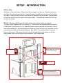
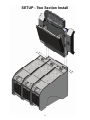
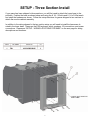
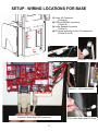
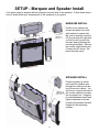
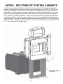
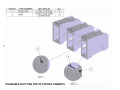
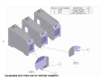
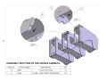
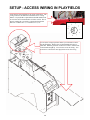
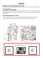
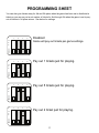
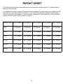
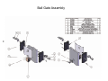
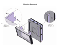
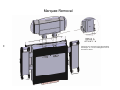
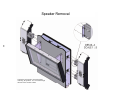
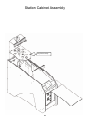
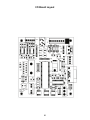
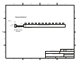
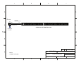
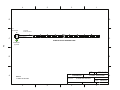
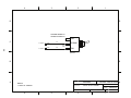
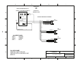
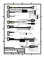
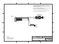
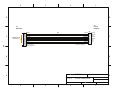
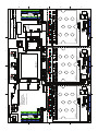
OWNERS AND SERVICE MANUAL
INNOVATIVE CONCEPTS IN ENTERTAINMENT INC.
1
TABLE OF CONTENTS
Safety and Warnings
4
Setup
Game Play
Setup
Two Section Install Diagram
Three Section Install Diagram
Wiring Locations for Base Diagram
Marquee and Speakers Install
Splitting of Station Cabinets
Accessing Wiring In Playfields
Meters and Tickets
Programming
Volume control
Trouble Shooting
5
6
7
8
9
10
14
15
18
Assembly Diagrams
Ball Gate Assembly
Monitor Removal
Marquee Removal
Speaker Removal
Glass, Playfield, and Playfield I/O Removal
PCB Layouts
Spare Parts
Wiring Diagrams
REVISION B : Photo Finish - ICE
19
20
21
22
23
24 - 25
26
27 - 38
6-26-09
3
SAFETY AND WARNINGS
BEFORE YOU BEGIN
WARNING: WHEN INSTALLING THIS GAME, A GROUNDED A.C. RECEPTACLE MUST BE USED. FAILURE
TO DO SO COULD RESULT IN INJURY TO YOURSELF OR OTHERS. FAILURE TO USE A GROUNDED RECEPTACLE COULD ALSO CAUSE IMPROPER GAME OPERATION, OR DAMAGE TO THE ELECTRONICS.
DO NOT DEFEAT OR REMOVE THE GROUNDING PRONG ON THE POWER CORD FOR THE SAME REASON AS GIVEN ABOVE. USING AN IMPROPERLY GROUNDED GAME COULD VOID YOUR WARRANTY.
HAVE A QUALIFIED ELECTRICIAN CHECK YOUR A.C. RECEPTACLE TO BE SURE THE GROUND IS FUNCTIONING PROPERLY. DO NOT WASH YOUR GAME WITH A PRESSURE WASHER.
AVERTISSEMENT: lors de l'installation de ce jeu, la terre AC récipient doit être utilisé. Ne pas le faire pourrait entraîner un préjudice à vous ou à d'autres. Le non-recours à la terre récipient pourrait également causer une mauvaise opération de jeu, ou les dommages causés à l'électronique. NE PAS détériorer ou de retirer la broche de
terre sur le cordon d'alimentation pour la même raison, comme indiqué ci-dessus. Indûment l'aide d'un jeu de la
terre pourrait annuler votre garantie. Ont un électricien qualifié de vérifier votre récipient AC pour s'assurer que le
sol fonctionne correctement. Ne lavez pas votre jeu avec une laveuse à pression.
INSTALLATION
The game comes ready to play with just a few simple things to keep in mind.
1. Plug the game into the A.C. outlet and turn on power to the game. The switch for the game is located on a
power module on the outside rear of the game.
THIS GAME IS DESIGNED TO DISSIPATE STATIC ELECTRICITY THROUGH THE GROUNDING PLANE OF THE
GAME. IF THE A.C. GROUND DOES NOT WORK, THE GAME COULD DISCHARGE STATIC ELECTRICITY
THROUGH THE GAME CIRCUITRY, WHICH COULD CAUSE DAMAGE.
2. Make sure the game is level after installation. It is necessary to make sure the game is level for safety
concerns.
3. Check that the A.C. voltage rating on the back of the game matches the A.C. voltage of your location.
THE POWER SUPPLY IS NOT VOLTAGE ADJUSTABLE. TO OPERATE THE GAME AT VOLTAGES OTHER THAN
THOSE IT WAS DESIGNED FOR. PLEASE CONTACT OUR SERVICE DEPARTMENT FOR VOLTAGE CONVERSION
INFORMATION.
WARNING
DO NOT remove any of the components on the main board (e.g. compact flash and eproms) while
the game is powered on. This may cause permanent damage to the parts and the main board. Removing any main board component part while powered on will void the warranty.
Ne retirez pas l'un des composants sur la carte principale (par exemple Compact Flash et
EPROMs), tandis que le jeu est sous tension. Cette mai causer des dommages permanents aux
parties et la carte principale. Suppression de tout bord principal élément sous tension alors que annulera la garantie.
NOTE: THIS GAME IS INTENDED FOR INDOOR USE ONLY.
ON THE BACK PANEL OF THE GAME: WARNING: SHOCK HAZARD - DO NOT OPEN. REFER
SERVICING TO SERVICE PERSONNEL.
REMARQUE: CE JEU EST DESTINÉ POUR USAGE À L'INTÉRIEUR SEULEMENT.
SUR LE PANNEAU ARRIÈRE DU JEU: AVERTISSEMENT: RISQUE DE CHOC - NE PAS OUVRIR. RÉPARATION À UN PERSONNEL DE SERVICE.
4
SETUP - INTRODUCTION
Game play:
Welcome to a day at the races. Players insert their coinage to join the race. Once the race starts
the player rolls their ball down the lane. Landing the ball in a yellow hole the horse will trot moving
one space. Lading the ball in a blue hole the horse will gallop moving two spaces. Landing the ball
in a red hole and the horse will sprint moving three spaces. The player that reaches the finish line
first wins the trophy!
Setup: (Please read through the entire setup instructions before you begin)
The game can be shipped in two or more sections. If the podiums are preassembled and attached
to the base all you will need to do is to attach the monitor cabinet assembly onto the base of the podium cabinet assembly. It is recommended that at least two people lift the monitor assembly onto the
podium base and attach the mounting hardware. See “Setup - Two Section Install” on the next
page for clarification. Now remove the back covers of the base and monitor cabinet so that the
monitor cable, audio, and AC plugs can be connected. See Pictures below.
The mounted connectors are
labeled “Right” and “Left” from
the front of the cabinets.
AC connector 2
AC connector 1
The Video connection connects to the
video connector located on the
computer installed in the podium 2.
5
SETUP - Two Section Install
6
SETUP - Three Section Install
If you game has been shipped in three sections, you will first need to attach the lower base to the
podiums. Position the base as shown below and using the 8 1/4 - 20 bolts and 8 1/4 x 3/4 flat washers install the hardware as shown. Follow the setup directions for games shipped in two sections to
attach the monitor cabinet assembly.
In addition to the wiring showed in the two section setup you will need to install the harnesses located in the lower base. These are the PS2 keyboard, serial, speakers, I/O connections, and power
connections. Please see “SETUP - WIRING LOCATIONS FOR BASE” on the next page for wiring
descriptions and locations.
7
SETUP - WIRING LOCATIONS FOR BASE
(1) Lower AC Connector
(Picture A)
(2) PS2 and SERIAL connectors
(Picture B)
(3) Lower Speaker Connector
(Picture C)
(4) DC power connector & 9 pin I/O connectors
(Picture D and E)
3
4
2
1
Picture A - Lower AC Connector
Picture E - 9 Pin I/O
Picture C - 4 Pin Lower Audio
FOR PS2 KEYBOARD
Picture B - Serial and PS2 Connectors.
8
4 Pin Lower Audio and DC Power
SETUP - Marquee and Speaker Install
Your game might be shipped with the marquee removed and or the speakers. Follow these instructions to attach either your marquee and or the speakers to your game.
MARQUEE INSTALL
Position your marquee as
shown and attach four bolts
with washers for each side.
Be sure to carefully insert the
AC plug through the right side
so that you do not pinch the
harness when tightening the
mounting hardware. Remove
the monitor cabinet back and
Connect the AC wiring. Replace the back panel.
SPEAKER INSTALL
Position speaker as shown
and insert the speaker wire
through the lower mount and
into the monitor cabinet. You
will have to remove the back of
the monitor cabinet to access
the mounting hole. Using the
provided hardware install and
tighten hardware as shown.
Connect the speaker harness.
Repeat for the remaining
speaker.
9
SETUP - SPLITTING OF STATION CABINETS
It might be necessary to split the three stations so that your game will fit through a standard door
opening. Open the bottom cabinet door and disconnect the wiring shown in “SETUP - WIRING LOCATIONS FOR BASE” section of the manual. Remove the upper and lower mounting hardware as
shown below. It will be necessary to have another person to stabilize the back section of your game
while removing the hardware and put aside. Remove the mounting hardware shown in diagrams
A,B,C “Splitting of the Station Cabinets”. Stations one and three have wiring which must be disconnected before splitting. Facing the cabinet, station one is located on the left and station three is located on the right. Remove the glass and playfield header as shown in “SETUP - ACCESS WIRING
IN PLAYFIELDS”. On Station one, disconnect J1, J2 and J17. On Station Three, disconnect J2 and
J17. You can now pull the cabinets apart.
10
11
DIAGRAM A:SPLITTING THE OF STATION CABINETS
12
DIAGRAM B:SPLITTING THE OF STATION CABINETS
13
DIAGRAM C:SPLITTING OF THE STATION CABINETS
SETUP - ACCESS WIRING IN PLAYFIELDS
At the back of each playfield are the wiring connections. The
wiring connectors are labeled to match the correct wiring
harness. If a playfield is replaced the station ID number must
be set to the correct station number it will be used in. This is
done by turning the “pot switch” to the desired station ID.
Station 1 would be set to 1, 2 would be set to 2, etc...
3
2
5
0
1
4
9
6
7
8
To access the wiring to split the cabinet you will need to remove
the playfield glass. Remove the two bolts holding the glass retainer bar. Slide the glass back as shown to remove. Lift the back
station header straight up. You can now access the wiring. You
do not have to lift out the inner playfield to access the wiring.
14
SETUP
METERS AND TICKET DISPENSER LOCATION
Each station has its own ticket dispenser, ticket meter and coin meter. Each is located through the
front of each station.
ACCESSING PROGRAMMING
To program the game, you will need to open the lower back cabinet door. You will find small a pcb
with two rotation switches at location SW4 and SW5. There is also a single bank of four dipswitch at
location SW3.
PROGRAM SWITCHES LOCATION
Located on SW4 and SW5 is a knob that can be rotated or dialed to the desire option number.
There is a small arrow (not the screw driver slot) that determines which number it is at.
SW3
1
1
3
2
O
F
F
5
5
9
6
6
9
4
4
4
0
3
1
2
2
0
3
SW5
7
8
15
7
SW4
8
PROGRAMMING SHEET
OPTION 1 (SW4) Cost Game. : This rotary switch determines how many pulses it takes before a
game can start. Fox example, setting this switch on 1 and you are accepting quarters it will require
one quarter to play. A setting of 4 would require either 4 quarters or $1 dollar to play (If a bill acceptor is installed).
0 = Free Play
1 = 1 pulses to start
2 = 2 pulses to start
3 = 3 pulses to start
4 = 4 pulses to start
5 = 5 pulses to start
6 = 6 pulses to start
7 = 7 pulses to start
8 = 8 pulses to start
9 = 9 pulses to start
Option 2 (SW5) Tickets per Station : This rotary switch determines how many tickets to payout to the
winners. Dipswitch 4 determines which table to use for how many tickets to payout. For example, a
setting of 8 and dipswitch 4 is off would pay out a total of 20 tickets but if dipswitch 4 was on it would
pay out 80 total tickets. Tickets can be either divided among players depending on their results of
the race or only given to the first place winner. This is configured by dipswitch 1. See dipswitch settings and Note 1 below.
TABLE 1 (Dipswitch 4 off)
0 = No Tickets
1 = 3 Ticket
2 = 5 Tickets
3 = 8 Tickets
4 = 10 Tickets
5 = 12 Tickets
6 = 15 Tickets
7 = 18 Tickets
8 = 20 Tickets
9 = 23 Tickets
TABLE 2 (Dipswitch 4 on)
0=25 Tickets
1=30 Tickets
2=35 Tickets
3=40 Tickets
4=45 Tickets
5=50 Tickets
6=60 Tickets
7=70 Tickets
8=80 Tickets
9=90 Tickets
Dip Switch Settings
1 = All or Distributed (see note 1)
2 = JFP Tickets for 4th and 5th place when distributed or 2nd-5th when set for all (see next page)
3 = JFP Tickets for 4th and 5th place when distributed or 2nd-5th when set for all (see next page)
4 = What table to use. On = Table 2 Off = Table 1.
Note 1:
Distribution: If this option is off, the tickets will be distributed by 60% to the first place winner, 30%
for the second place winner, 10 % for the third place winner, and JFP tickets for the fourth and fifth.
For example if you turn this option off and are paying out a total of 10 tickets, it would pay 6 tickets
to the winner, 3 tickets to the second place winner and 1 ticket to the third place winner. If there are
more players, none would be paid to them unless you have JFP set.
All: If this option is on, the tickets would all pay to the first place winner and none would be paid to
the remaining players unless you have JFP set.
16
PROGRAMMING SHEET
You can also give tickets away for 4th and 5th place when the game has been set to distribute its
tickets or you can pay out a set number of tickets for 2nd through 5th when the game is set to payout all tickets to 1st place winner. See below for settings.
1
2
3
4
Disabled
Game will pay out tickets per game settings.
O
F
F
1
2
3
4
Pay out 1 tickets just for playing.
1
2
3
4
Pay out 5 tickets just for playing.
1
2
3
4
O
F
F
O
F
F
O
F
F
Pay out 2 ticket just for playing.
17
PAYOUT SHEET
The chart below shows the recommended amount of tickets that should be paid out to achieve your desired payout percentage.
For example if you wish to have a 30% payout and are charging .25 cent per play you will need to set Dip
switch 4 to off, turn rotary switch 5 to position 3. If you wish to distribute the tickets among the winners,
you will also need to set dipswitch 1 to the off position. Regardless of what dipswitch 1 is set to the total
number of tickets that are paid out will be 8 or equal 8.
Game Cost 20% Payout 25%Payout 30% Payout 35% Payout 40% Payout
.25¢
5 Tickets
6 Tickets
8 Tickets
9 Tickets
10 Tickets
.50¢
10 Tickets
12 Tickets
15 Tickets
18 Tickets
20 Tickets
.75¢
15 Tickets
18 Tickets
23 Tickets
27 Tickets
30 Tickets
$1.00
20 Tickets
24 Tickets
30 Tickets
36 Tickets
40 Tickets
$1.50
30 Tickets
36 Tickets
45 Tickets
54 Tickets
60 Tickets
$2.00
40 Tickets
48 Tickets
60 Tickets
72 Tickets
80 Tickets
18
SETUP
Volume Control
To access the volume control, open the coin door of station 2 (Center station). Located slightly
above on the left is a small amplifier. A volume knob is located toward the lower section of the amplifier. See picture below.
PS2 Keyboard
Located below the I/O board is the control switch to enable the keyboard. A LED indicator will be on
when the keyboard is enabled. While the keyboard is enabled, the LED indicator will be on. For
proper operation of your game, this switch needs to be in the off position. The LED indicator will be
off also. You do not need to enable the keyboard unless directed by ICE Service department.
TROUBLE SHOOTING
CAUTION
This game uses complex electronic components that are very sensitive to static electricity. Observe precautions below before handling these electronics. Failure to do so may void the warranty and damage electronic
assemblies.
Before servicing electronics, turn off AC power to the game. Wait for capacitors to discharge.
DO NOT remove any of the components on the main board (e.g. compact flash and eproms) while the game is
powered on. This may cause permanent damage to the parts and the main board.
Before touching or handling electronic assemblies, discharge static electricity on your body. To discharge this
static, begin by connecting the line cord to a grounded outlet. Don’t turn on the game. Next, touch the safety
ground stud of the power supply chassis.
Store electronic assemblies in an anti-static area. Use anti-static bags to store or transport the game circuit boards.
Don’t remove or connect electronic assemblies when cabinet power is on. Otherwise, you’ll damage electronic assemblies and void the game’s warranty.
After you complete maintenance or service, replace ground wires, shields, safety covers and install and tighten
ground and mounting screws.
19
Ball Gate Assembly
20
Monitor Removal
21
Marquee Removal
22
Unplug the AC connector before disassembling
the marquee. It is accessed through the back of
the monitor cabinet.
Speaker Removal
23
Unplug the each speaker connection before
removing the speakers. It is accessed through
the back of the monitor cabinet.
Station Cabinet Assembly
Playfield assembly.
24
I/O Board Layout
25
I/O Board Layout
26
Spare Parts
EV2009
8975PHX
CL2011
E00211
HH5005
PH1027
PH2032X
PH2037X
PH2037B
PH7003
PH7031
RR1024
MON47EST
PH2000
PH2034X
PH2034B
E00038
E00382
PH7035
PH7040
PH7041
PH7042
PH7050
PH7051
PH9001
Audio Amp
Assembly Blue Meteor Light
Solenoid
Low ticket switch
Ticket Dispenser (Entropy)
Ball gate
RGB LED Pcb
Ball Sensor PCBA
Call Sensor PCBB
Playfield
Decal Tickets
Double ticket bin
47” LCD Monitor
Computer
PCBA Main I/O
PCBB Main I/O
Fuse 4 amp
Bulb CF 27W
Front decal
Decal Podium number 1
Decal Podium number 2
Decal Podium number 3
Decal Podium side left
Decal Podium side right
Service Manual
27
4
3
2
1
D
D
DRILL HOLE TO
5/16" FOR LED
#PH2052LX – KEYBOARD
CONTROL HARNESS
C
14"
red
violet/yellow
PH
J21
1
2
3
4
1
2
C
10"
2 PIN MOLEX HOUSING #E02089
MINI KK PIN #E02074
red
white/yellow
violet/yellow
black
28
SOLDER WIRES TO
LEADS ON SWITCH
4 PIN CST-100 #E02722
CST PIN #E00383
white/yellow
.187 #E00651
ON
black
M
.187 #E02909
COMM
12"
12"
black
B
LED HOLDER
#E01017
.187 #E00651
black
M
.187 #E02909
ON
B
TOGGLE SWITCH
ASY #E02390X
#1029 BRACKET
1029PHX
PART NO.
A
DESCRIPTION
4
3
2
PH1000X - PHOTO FINISH
FILENAME
PH1000X.VSD
DRAWN BY
NBRANCATO
KEYBOARD SWITCH ASSEMBLY
2/25/09
DATE
TITLE
REVISED
6/25/09
PAGE
1
1 OF 27
A
4
3
2
1
D
D
TO:
PH2051HX
FULL LENGTH
15"
C
blue
black
red
yellow
blue
black & red & yellow
PH
1
2
C
2 PIN PLUG #E02103
SOLID PIN #E08260
29
METEOR LIGHT #8975
CUT OFF 4 PIN CONNECTOR AND
REPLACE WITH 2 PIN M & L PLUG
B
B
QTY 3
A
8975PHX
PART NO.
NOTES:
1. NO ZIP TIES, WIRES IN CLEAR TUBING
2. COMES TWO PER PACKAGE
4
3
2/25/09
2
PH1000X - PHOTO FINISH
FILENAME
PH1000X.VSD
DRAWN BY
NBRANCATO
BLUE METEOR LIGHT
DESCRIPTION
DATE
TITLE
PER GAME
REVISED
6/25/09
PAGE
1
2 OF 27
A
4
3
2
1
D
D
TO:
POWER SUPPLY
#RB2010
MONITOR
POWER SUPPLY
C
BROWN (600V)
TO:
#PH2061LX
#E00653
C
L
BA
30
1
2
3
BROWN (600V)
GREEN/YELLOW (600V)
BLUE (600V)
8"
GREEN/YELLOW (600V)
FG
#E20217
3 PIN PLUG #E02206
MALE PIN #E08260
BLUE (600V)
#E00653
N
B
B
QTY 2
BA2063LX
PART NO.
A
4
3
2/25/09
2
PH1000X - PHOTO FINISH
FILENAME
PH1000X.VSD
DRAWN BY
NBRANCATO
MONITOR AC
DESCRIPTION
DATE
TITLE
PER GAME
REVISED
6/25/09
PAGE
1
3 OF 27
A
4
3
2
COIN LIGHT
2"
D
12"
12"
1
orange/black
black/orange
D
.110 #E00650
.110 #E00650
BF
COIN COIN +
12V
31
GROUND
COIN PULSE
12V
COIN LIGHT
12V
.250
#E00654
M
C
black
.250 FLAG
#E00648
M
.250
#E00654
white/red
.250 FLAG
#E00648
BLACK
RED
0000000000
C
1
2
3
4
5
6
7
6"
8 black
9 KEY E02991
10 black
6"
11 white/brown
12 orange/black
13
2"
14 black
#2558
15 black
2"
2"
16 red
#2558
17 black/orange
6"
18 orange
19
orange
M
.250
#E00654
12v
COUNTER
#PC20224
#8211
T-SPLICE
CST HOUSING #E02713
CONTACT PIN #E00383
B
B
.110 #E00650
DECAL# 7079 (THIS SIDE UP)
ON “WINDOW” SIDE OF CONNECTOR
QTY 3
A
BF340X
PART NO.
NOTES:
1. OPTIONAL FOR 340 CASHFLOW GAMES
DESCRIPTION
4
3
2
PH1000X - PHOTO FINISH
FILENAME
PH1000X.VSD
DRAWN BY
NBRANCATO
CASH FLOW 340 ADAPTER
2/25/09
DATE
TITLE
PER GAME
REVISED
6/25/09
PAGE
1
4 OF 27
A
4
3
2
1
D
D
Cut wires on LED strip to 18"
add zip tie for strain relief
TO:
#PH2037X
PH
J16
C
+12VDC
Station Lite
1
2
red
black
18"
2 PIN AMP HOUSING #E02240
CONTACT PIN #E02201
C
E00413 LED FLX ST WHT 18
W
DECAL #FR7033 (x1)
32
SETTING A7 ON PIN
MACHINE
B
B
QTY 3
E00413PHX
PART NO.
A
DESCRIPTION
4
3
2
PH1000X - PHOTO FINISH
FILENAME
E00413PHX.VSD
DRAWN BY
NBRANCATO
WHITE LED FLEX STRIP
2/25/09
DATE
TITLE
PER GAME
REVISED
6/25/09
PAGE
1
5 OF 27
A
4
3
2
1
D
D
TO:
#PH2085MX
LED POWER
HARNESS #PE2063LX
PH
1
2
C
8"
red
black
2 PIN PLUG #E02103
SOLID PIN #E02100S
+
+
+
+
+
+
+
+
+
-
-
-
-
-
-
-
-
-
C
E00414 LED TAPE ST BLU
STRIP IS 20 CUT LENGTHS LONG
BLUE DOT
(x1) #7901
33
B
B
QTY 4
A
E00414PHX
PART NO.
NOTES:
1. GOES TO FLOOR
DESCRIPTION
4
3
2
PH1000X - PHOTO FINISH
FILENAME
E00413PHX.VSD
DRAWN BY
NBRANCATO
60 BLUE LED TAPE STRIP
2/25/09
DATE
TITLE
PER GAME
REVISED
6/25/09
PAGE
1
6 OF 27
A
4
3
2
1
D
D
TO:
#PH2085MX
LED POWER
HARNESS #PE2063LX
PH
1
2
C
8"
red
black
2 PIN PLUG #E02103
SOLID PIN #E02100S
+
+
+
+
+
+
+
+
+
-
-
-
-
-
-
-
-
-
C
E00459 LED TAPE ST GRN
STRIP IS 20 CUT LENGTHS LONG
34
GREEN DOT
(x1) #7903
B
B
QTY 4
A
E00459PHX
PART NO.
NOTES:
1. GOES TO FLOOR
DESCRIPTION
4
3
2
PH1000X - PHOTO FINISH
FILENAME
E00413PHX.VSD
DRAWN BY
NBRANCATO
60 GREEN LED TAPE STRIP
2/25/09
DATE
TITLE
PER GAME
REVISED
6/25/09
PAGE
1
7 OF 27
A
4
3
2
1
D
D
SOLDER WIRES TO
LEADS ON SWITCH
ON
C
.187 #E02909 M
.187 #E02909 M
2 ½”
black
black
2 ½”
NO
SHRINK
TUBE
C
COMM
35
ON
TOGGLE SWITCH
#E02390
B
B
A
E02390X
PART NO.
NOTES:
1. PART OF 1029PHX
DESCRIPTION
4
3
2
PH1000X - PHOTO FINISH
FILENAME
E00413PHX.VSD
DRAWN BY
NBRANCATO
TOGGLE SWITCH ASSEMBLY
2/25/09
DATE
TITLE
REVISED
6/25/09
PAGE
1
8 OF 27
A
4
3
1
DECAL #7086
6 AMP
250V
#PH2007X-POWER MODULE ASY
DECAL #7077
#E02295 – FUSE 6 AMP 250V (MDA - 6)
#2892-POWER MODULE
CORCOM ( PELSOSSXO)
D
2
TIME DELAY FUSE
D
BLUE
A
B
C
.187 #E00651
D
.187 #E00651
#SX2055X-POWER MODULE HARNESS
6 AMP FUSE
#E20217
10 "
BROWN
BROWN x 2
GREEN/YELLOW x 2
BLUE x 2
GREEN/YELLOW x 2
3 PIN CAP #E02288
FEMALE #E02013
#E00638
.187
C
TO:
PH2061X
1
2
3
C
15 "
GREEN/YELLOW
TO:
PH2062X
3 "
36
BROWN x 2
GREEN/YELLOW x 2
BLUE x 2
1
2
3
3 PIN CAP #E02288
FEMALE #E02013
B
ALL WIRE IS 600V
#8872
BROWN
#2844
GREEN
#8871
BLUE
6 "
TO:
PH2063X
BROWN
GREEN/YELLOW
BLUE
B
1
2
3
3 PIN CAP #E02288
FEMALE #E08259
A
IN A 220V GAME:
REMOVE 6 AMP FUSE AND
REPLACE WITH 3 AMP MDA FUSE
#E02315
PH2007X
PART NO.
DESCRIPTION
4
3
2
PH1000X - PHOTO FINISH
6 AMP POWER MOD ASSEMBLY
WITH SX2055X HARNESS
2/25/09
DATE
TITLE
REVISED
6/25/09
FILENAME
E00413PHX.VSD
DRAWN BY
NBRANCATO
PAGE
1
9 OF 27
A
4
3
2
1
J14
Bill
+12VDC
Gnd
1
2
3
4
TO:
8975PHX
102"
orange/white
black/white
4 PIN CST-100 #E02722
CST PIN #E00383
orange/white
black/white
2 PIN CAP #E02181
FEMALE PIN #E02102
SPIRAL WRAP – ¼”
#E08069 @ 6 ½"
88"
102"
black
orange
10"
10"
yellow/brown x 2
J15
Coin Counter
+12VDC
Ticket Counter
92"
yellow/brown
orange
yellow/red
1
2
3
C
orange
3 PIN AMP HOUSING #E02945
CONTACT PIN #E02201
.110 #E00650
.110 #E00650
.110 #E00650
.110 #E00650
COIN
red
black
12V COUNTER
#PC20224
TICKET
red
black
C
12V COUNTER
#PC20224
.250
#E00653T
white/brown
black
yellow/red
yellow/brown
orange
tan/black
70"
ORANGE
BLUE/BLACK
coin in/swipe signal
ground
ticket counter
coin counter
+12V DC
inhibit (EMBED)
#E08492
Splice cap
J9
1
2
3
4
5
6
COIN
LIGHTS
32"
81"
4 PIN CST-100 #E02722
CST PIN #E00383
Sol +
Sol -
orange
black
#E02558
orange
tan/black
white/brown
black
1
2
3
4
orange
black x 2
#E02815
yellow/red x 2
J7
+12VDC
inhibit
card swipe
Gnd
#E02558
.250 FLAG
#E00648
black x 2
8"
10 PIN CST-100 #E02851
CST PIN #E00383
ALL TO:
PH2034X
white/red
20"
102"
white/red
D
.250 FLAG
#E00648
black x 2
106"
0000000000
Inhibit
OP_A
OP_B
OP_C
OP_D
1
2
3
4
5
6
7
8
9
10
0000000000
Gnd
+12VDC
OP_E
OP_F
COIN
SWITCHES
white/red x 2
J5
D
1
2
ORANGE
BLUE/BLACK
TO:
SOLENOID
.187 #E00651 #CL2011
.187 #E00651
6 PIN AMP HOUSING #E02944
CONTACT PIN #E02201
B
B
J8
+12 VDC
Ticket Run
Ticket Sense
Gnd
ORANGE
violet/white
violet/blue
BLACK
1
2
3
4
SPIRAL WRAP – ¼”
#E08069 @ 4 ½”
129"
11 ½”
PH
violet/blue
BLACK + black
violet/white
ORANGE+orange
4 PIN AMP HOUSING #E02429
CONTACT PIN #E02201
1
2
3
4
T Sense
P GND
T Run
+ 12 VDC
4 PIN MLX CAP #E02158
FEMALE PIN #E02176
PIN 2,4 #E08177
12"
TO:
LOW TICKET SWITCH
.187 #E00651
.187 #E00651
A QTY 3
PART NO.
PER GAME
PH2051HX
2/25/09
4
REVISED
orange
violet/green
LOOK FOR
BLACK DOT
1
2
2 PIN MOLEX HOUSING #E02089
MINI KK PIN #E02074
TITLE
FILENAME
E00413PHX.VSD
DRAWN BY
NBRANCATO
6/25/09
PAGE
A
INSERT RED FLASHING LED #E08212 INTO RUBBER SPACER FROM
LED HOLDER #E01017, THEN INSERT THESE PIECES WITH LONG
LEAD TO PIN 1 (orange wire).
PH1000X - PHOTO FINISH
FOLD WIRES OVER OPPOSITE SIDES OF CONNECTOR AND COVER
WITH 3/8" CLEAR SHRINK TUBE #E00241 @ 1"
PODIUM
DESCRIPTION
DATE
black
19 ¼”
violet/green
21 ½”
DO NOT OVERHEAT THIS
RUBBER GROMMET
IT WILL BREAK DOWN
ADD ZIP TIE AT END OF SHRINK TUBE TO PREVENT SLIPPING
10 OF 27
3
2
37
1
4
3
2
1
INSERT RED LED #E20429 (NON-FLASHING) INTO RUBBER SPACER
FROM LED HOLDER #E01017, THEN INSERT THESE PIECES WITH
LONG LEAD TO PIN 1 (red wire).
FOLD WIRES OVER OPPOSITE SIDES OF CONNECTOR AND COVER
WITH 3/8" CLEAR SHRINK TUBE #E00241 @ 1"
D
D
ADD ZIP TIE AT END OF SHRINK TUBE TO PREVENT SLIPPING
ATTACH LED HOLDER TO HARNESS WITH ZIP TIE
TO:
PH2034X
DO NOT OVERHEAT THIS
RUBBER GROMMET
IT WILL BREAK DOWN
PH
10"
J21
1
2
3
4
C
14"
red
violet/yellow
red
white/yellow
violet/yellow
black
1
2
C
2 PIN MOLEX HOUSING #E02089
MINI KK PIN #E02074
4 PIN CST-100 #E02722
CST PIN #E00383
38
12"
2"
white/yellow
black
.187 #E00651
.187 #E00651
TO:
E02390X
B
A
PH2052LX
PART NO.
NOTES:
1. GOES TO CRITICAL
2. USED IN 1029PHX
3
2/25/09
2
TITLE
PH1000X - PHOTO FINISH
FILENAME
E00413PHX.VSD
DRAWN BY
NBRANCATO
KEYBOARD CONTROL
DESCRIPTION
DATE
4
B
REVISED
6/25/09
PAGE
1
11 OF 27
A
4
3
2
1
D
D
TO:
I/O PCB
#PH2034X
TO:
#PH2080LX
J2
C
PH
ORANGE DECAL
#PH7070 (x2)
1
2
3
4
5
6
7
8
9
28"
WHITE
GREEN
RED
ORANGE
ORANGE
BLACK
BLACK
BLACK
WHITE
GREEN
RED
ORANGE
ORANGE
BLACK
BLACK
BLACK
1
2
3
4
5
6
7
8
Receive
Transmit
Sync
+12VDC
+12VDC
Gnd
Gnd
Gnd
C
8 PIN AMP HOUSING #E02405
CONTACT PIN #E02201
39
9 PIN CAP #E02551
FEMALE PIN #E02102
B
B
PH2086LX
PART NO.
A
DESCRIPTION
4
3
2
PH1000X - PHOTO FINISH
FILENAME
E00413PHX.VSD
DRAWN BY
NBRANCATO
STATION COMMUNICATION
2/25/09
DATE
TITLE
REVISED
6/25/09
PAGE
1
27 OF 27
A
A
B
red
black
PH2051HX
SPEAKER BOX #PH3075X
orange 1 1 red
violet /green 2 2 black
red 1 1 orange x 2
black 2 2 violet /blue x 2
BLUE LED TAPE STRIP #E00414PHX
orange x 2 1 1 red
violet /blue 2 2 black
BLUE LED TAPE STRIP #E00414PHX
red 1 1 orange x 2
black 2 2 violet /green x 2
GREEN LED TAPE STRIP #E00459PHX
1
2
J2
C
AR2007
6 x 9 SPEAKER
4 OHM
red/white +
brown/white
-
WHITE
GREEN
RED
ORANGE
ORANGE
BLACK
BLACK
BLACK
1
2
3
4
5
6
7
8
1 blue
2 black, red, yellow
PH2037X
Receive
Transmit
Sync
+12VDC
+12VDC
Gnd
Gnd
Gnd
D
POWER ENTRY MODULE
PH2007X
I
O
GREEN LED TAPE STRIP #E00459PHX
J14
1
2 orange/white
3 black/white
4
+12 VDC
Gnd
J16
1 red
2 black
+12VDC
Station light
PH2085MX
BROWN
GRN/YLW
BLUE
BROWN x 2
GRN/YLW x 2
BLUE x 2
red/white
brown/white
orange
violet/blue
violet/green
1
2
3
1
2
3
1
2
3
1
2
3
1
2
3
4
5
6
1
2
3
4
5
6
PH2032X
COIN SWITCHES
black x 2
white/red x 2
orange x 2
black x 2
orange
black
ORANGE
BLUE/BLACK
CL2011 SOLENOID
BALL GATE
black x 2
4
PH2061LX
BROWN
GRN/YLW
BLUE
1
2
3
1
2
3
BROWN
GRN/YLW
BLUE
WHITE LED STRIP #E00413PHX
CHANGE FUSE FROM 6A TO 3A
white/red
COIN
LIGHTS
PH2063LX
NOTE:
FOR 220V GAME INSERT
WF2002CEAX STEP DOWN
TRANSFORMER AT HARNESS
WITH RED TRIANGLE
BLACK
GREEN
WHITE
BROWN x 2
GRN/YLW x 2
BLUE x 2
BROWN
GRN/YLW
BLUE
yellow/red x 2
orange
red
black
black
red
0000
TICKET
0000
COIN
1
2
BROWN
GRN/YLW
BLUE
1
2
3
1
2
3
BROWN
GRN/YLW
BLUE
BROWN
GRN/YLW
BLUE
PH2062LX
1
2
3
1 violet/green
2 orange
3 violet/blue
1
2
3
1
2
3
1
2
3
PH2081LX
FLASHING LOW
TICKET LED
HH5005
TICKET
DISPENSER
LOW TICKET
SWITCH
black
violet/green
1
2
3
4
1
2
3
BROWN
GRN/YLW
BLUE
BROWN
GRN/YLW
BLUE
BROWN
GRN/YLW
BLUE
yellow/green
orange
yellow/blue
PH2067LX
violet/blue
BLACK & black
violet/white
ORANGE & orange
orange
violet/green
8975PHX - BLUE METEOR LIGHT
red x 2
yellow/brown x 2
coin in/swipe signal
ground
ticket counter
coin counter
+12V DC
inhibit (EMBED)
CARD SWIPE SYSTEM
white/brown
black
yellow/red
yellow/brown
orange
tan/black
J17
1 violet/green
2 orange
3 violet/blue
1
2
3
J1
red/gray
brown/gray
orange
yellow/blue
yellow/green
Gnd
+12 VDC
J5
1 black
2 orange
3
4
5
6
7
8 white/red
9
10
Coin in
J15
1 yellow/brown
2 orange
3 yellow/red
Coin counter
+12 VDC
Ticket Counter
orange
tan/black
white/brown
black
J7
1
2
3
4
+12 VDC
inhibit
Card ok
Gnd
J9
1 ORANGE
2 BLUE/BLACK
3
4
5
6
+12 VDC
Ball gate Solenoid
J13
1 red
2 green
3 black
+12 VDC
Data
Gnd
ORANGE
violet/white
violet/blue
BLACK
J8
1
2
3
4
+12 VDC
Ticket run
Ticket sense
Gnd
PH2084LX
BLACK
BLACK
BLACK
ORANGE
ORANGE
RED
GREEN
WHITE
1
2
3
4
5
6
7
8
Gnd
Gnd
Gnd
+12VDC
+12VDC
Sync
Receive
Transmit
BROWN x 2
GRN/YLW x 2
BLUE x 2
24VDC
POWER
SUPPLY
BA2063LX
ORANGE
BLACK
1
2
1
2
3
3
red/gray
brown/gray
brown/white
red/white
BLACK
GRN/YLW
WHITE
EV2009
AUDIO
AMP
1 blue
2 black, red, yellow
ORANGE
BLACK
RED
1
2
3
4
E02731
1
2
3
1 ORANGE
2 BLACK
PH2037X
BLACK
BLACK/WHITE
GREEN/WHITE
GREEN
red
black
1
2
1
2
3
PH2066LX
PH2068LX
12VDC
POWER
SUPPLY
#RB2010
BA2063LX
BROWN
GRN/YLW
BLUE
BROWN
GRN/YLW
BLUE
J2
1
2
3
PH2082LX
BLACK x 2
RED x 2
BROWN x 2
GRN/YLW x 2
BLUE x 2
1
2
3
4
1
2
3
4
VOLUME
CONTROL
1
2
3
BLACK
GRN/YLW
WHITE
PH2086LX
black x 2
black x 2
orange x 2
black x 2
orange
black
ORANGE
BLUE/BLACK
CL2011 SOLENOID
BALL GATE
COIN SWITCHES
white/red x 2
white/red
COIN
LIGHTS
PH2051HX
WHITE
GREEN
RED
ORANGE
ORANGE
BLACK
BLACK
BLACK
yellow/red x 2
orange
1
2
3
4
5
6
7
8
red
black
black
red
WHITE
GREEN
RED
ORANGE
ORANGE
BLACK
BLACK
BLACK
BROWN
GRN/YLW
BLUE
coin in/swipe signal
ground
ticket counter
coin counter
+12V DC
inhibit (EMBED)
0000
TICKET
0000
COIN
1
2
3
BLACK
GRN/YLW
WHITE
PH2080LX
1
2
2
LOW TICKET
SWITCH
black
black
1 violet/green
2 orange
3 violet/blue
ON
COMM
ON
1
2
red
black
PH2084LX
1
2
J1
1
2
3
4
1
2
3
4
5
6
7
8
J2
#1029PHX KEYBOARD CONTROL
black
white/yellow
red
violet/yellow
I/O PCB
PH2034X
FLASHING LOW
TICKET LED
HH5005
TICKET
DISPENSER
black
violet/green
1
2
3
4
1
2
3
PH2081LX
violet/green
orange
violet/blue
MARQUEE #PH7028X
1
2
3
violet/blue
BLACK & black
violet/white
ORANGE & orange
orange
violet/green
8975PHX - BLUE METEOR LIGHT
red x 2
yellow/brown x 2
1
2
3
4
5
6
7
8
CARD SWIPE SYSTEM
white/brown
black
yellow/red
yellow/brown
orange
tan/black
WHITE LED STRIP #E00413PHX
PH2083MX
MON47EST
PH2032X
red/gray
brown/gray
brown/white
red/white
PH2060LX
1
2
3
47" LCD MONITOR
PH2064LX
BROWN x 2
GRN/YLW x 2
BLUE x 2
J1
BLACK
BLACK x 2
ORANGE
ORANGE x 2
WHITE
GREEN
RED
ORANGE
ORANGE
BLACK
BLACK
BLACK
1
2
3
4
5
6
7
8
Receive
Transmit
Sync
+12VDC
+12VDC
Gnd
Gnd
Gnd
J14
1
2 orange/white
3 black/white
4
+12 VDC
Gnd
J16
1 red
2 black
+12VDC
Station light
2
J2
3
Gnd
+12 VDC
J5
1 black
2 orange
3
4
5
6
7
8 white/red
9
10
Coin in
J15
1 yellow/brown
2 orange
3 yellow/red
Coin counter
+12 VDC
Ticket Counter
orange
tan/black
white/brown
black
J7
1
2
3
4
+12 VDC
inhibit
Card ok
Gnd
J9
1 ORANGE
2 BLUE/BLACK
3
4
5
6
+12 VDC
Ball gate Solenoid
J13
1 red
2 green
3 black
+12 VDC
Data
Gnd
ORANGE
violet/white
violet/blue
BLACK
J8
1
2
3
4
+12 VDC
Ticket run
Ticket sense
Gnd
BLACK
BLACK
BLACK
ORANGE
ORANGE
RED
GREEN
WHITE
1
2
3
4
5
6
7
8
Gnd
Gnd
Gnd
+12VDC
+12VDC
Sync
Receive
Transmit
ORANGE
ORANGE
BLACK
BLACK
WHITE
GREEN
RED
ORANGE
ORANGE
BLACK
BLACK
BLACK
WHITE
GREEN
RED
ORANGE
ORANGE
BLACK
BLACK
BLACK
1
2
3
4
5
6
7
8
1 blue
2 black, red, yellow
PH2037X
Receive
Transmit
Sync
+12VDC
+12VDC
Gnd
Gnd
Gnd
DATE
E02247
E00474
PH2032X
REVISED
3 PLAYER GAME
black x 2
black x 2
orange x 2
black x 2
orange
black
ORANGE
BLUE/BLACK
CL2011 SOLENOID
BALL GATE
PH2085MX
7/15/09
yellow/red x 2
orange
red
black
black
red
0000
TICKET
0000
COIN
1
orange 1 1 red
violet /green 2 2 black
orange x 2 1 1 red
violet /blue 2 2 black
SPEAKER BOX #PH3075X
red 1 1 orange x 2
black 2 2 violet /blue x 2
red 1 1 orange x 2
black 2 2 violet /green x 2
1 OF 1
NBRANCATO
DRAWN BY
PAGE
PH1000X SYSTEM
SCHEMATIC.VSD
FILENAME
1
2
1
2
3
4
FLASHING LOW
TICKET LED
HH5005
TICKET
DISPENSER
LOW TICKET
SWITCH
black
violet/green
violet/blue
BLACK & black
violet/white
ORANGE & orange
orange
violet/green
8975PHX - BLUE METEOR LIGHT
red x 2
yellow/brown x 2
coin in/swipe signal
ground
ticket counter
coin counter
+12V DC
inhibit (EMBED)
CARD SWIPE SYSTEM
white/brown
black
yellow/red
yellow/brown
orange
tan/black
PH2051HX
WHITE LED STRIP #E00413PHX
PH2000
COMPUTER
KEYBOARD
COIN SWITCHES
white/red x 2
white/red
COIN
LIGHTS
1
PH1000X – PHOTO FINISH SYSTEM SCHEMATIC
12/3/07
E00255
DESCRIPTION
TITLE
J14
1
2 orange/white
3 black/white
4
+12 VDC
Gnd
GREEN LED TAPE STRIP #E00459PHX
4
Gnd
+12 VDC
J16
1 red
2 black
+12VDC
Station light
E02731
J5
1 black
2 orange
3
4
5
6
7
8 white/red
9
10
Coin in
orange
tan/black
white/brown
black
J7
1
2
3
4
+12 VDC
inhibit
Card ok
Gnd
J17
1 violet/green
2 orange
3 violet/blue
Green
+12VDC
Blue
J15
1 yellow/brown
2 orange
3 yellow/red
Coin counter
+12 VDC
Ticket Counter
red/white
brown/white
orange
violet/blue
violet/green
1
2
3
4
5
6
BLUE LED TAPE STRIP #E00414PHX
POWER CORD
J1
1
2
3
4
5
6
BLUE LED TAPE STRIP #E00414PHX
J13
1 red
2 green
3 black
+12 VDC
Data
Gnd
ORANGE
violet/white
violet/blue
BLACK
J8
1
2
3
4
red/white
brown/white
orange
violet/blue
violet/green
+12 VDC
Ball gate Solenoid
-
AR2007
6 x 9 SPEAKER
4 OHM
red/white +
brown/white
+12 VDC
Ticket run
Ticket sense
Gnd
J9
1 ORANGE
2 BLUE/BLACK
3
4
5
6
GREEN LED TAPE STRIP #E00459PHX
BLACK
BLACK
BLACK
ORANGE
ORANGE
RED
GREEN
WHITE
1
2
3
4
5
6
7
8
red
white/yellow
violet/yellow
black
Gnd
Gnd
Gnd
+12VDC
+12VDC
Sync
Receive
Transmit
6A MDQ
J21
1
2
3
4
A
B
C
D
Contacts at SEGA
Machine Sales
Telephone: +44 (0) 208 391 8090
Fax: +44 (0) 208 391 8099
www.sega-amusements.co.uk
SEGA Spares
Telephone: +44 (0) 208 391 8060
Fax: +44 (0) 208 391 8096
www.segatotalsolutions.com
Customer Services
Telephone: +44 (0) 208 391 8065
Fax: +44 (0) 208 391 8096