1
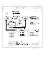
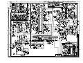
ELENBERG 2910F, CAMERON STV-2937
DISTAR
SERVICE MANUAL
DT-2977
1. Caution……………………………………………………………2
2. Specification………………………………………………………6
3. BOM List ……………………… …………………………………9
4. Alignment Procedure………………………………………….…35
5. Block Diagram……………………………………………………39
6. Schematic Diagram………………………………………………40
7. PCB Layout………….……………………………………………41
8. Explode View Diagram……………………………………………43
This manual is the latest at the time of printing, and does not
include the modification which may be made after the printing, by
the constant improvement of product.
TCL M113A chassis alignment instruction
Enter factory mode in production line
Simply press the D-mode key on the factory remote handset.
Enter service mode
Press and hold the VOLUME DOWN key tightly on the unit until minimum level and don’t release the
VOLUMN DOWN key, then press the DISPLAY key on the remote handset.
“D” letter on the screen indicated that the factory mode was entered. Now you can use the shortcut key
to access the factory menu. All change in factory data will save in EEPROM automatically
Note:
1. You can disable the D-Mode key (on factory remote handset) by change “BIT-0” of “OPT” to “0”.
If the D-Mode key was disabled, you can’t enter D-Mode by the D-mode key on the factory remote
(but you can still enter service mode). It is suggested to disable the D-Mode key before the set
leave the factory.
2. On the factory remote handset, you can find the “I²C” key. It can cut off the I2C control from the
CPU to other IC. This is only useful when automatic adjustment of white balance.
3. All system data in menu of “key 6” must keep unchanged when servicing. Otherwise, the set may
not work properly.
Setting method:
No Adjustment Data Name (default Conditions and
Setting method (need enter D-mode)
Items
value inside blanket)
input signal
1
Screen
-----------“IRGB cut off” Press “MUTE” key on the remote handset
voltage
must set to 80 (all
and the screen will become a horizontal
pattern)
line. Then adjust the “screen” VR on the
flyback until the horizontal line can just
be seen (minimum visible intensity).
2 Focus voltage
------------
3
HIT(11)
VP50(04)
VLIN(0B)
VSC(09)
VBLK(00)
VCEN(1B)
OSDH(1F)
DPC43(00)
Vertical
geometry for
PAL system
(Key 1)
Cross hatch
pattern.
Adjust the “focus” VR on the flyback
until the screen becomes clear.
Input a PAL cross Adjust HIT for vertical amplitude.
hatch pattern. Adjust VP50 for vertical position.
Adjust VLIN for vertical linearity.
Adjust VSC for vertical S-correction
(Normally use default value)
Adjust VCEN for vertical position
Adjust OSDH for OSD position
Same as DPC, adjust it on EXPAND 4:3
mode.
Input a NTSC
cross hatch
pattern.
4
Vertical
geometry for
NTSC system
(Key 1)
HITS(11)
VP60(02)
VLIS(0A)
VSS(08)
VBLK(00)
VCEN(1C)
OSDHS(1D)
DPC43S(00)
5
Horizontal
geometry for
PAL system
(Key 2)
HPOS(0C)
DPC(23)
KEY(20)
WID(22)
ECCT(09)
ECCB(0A)
VEHT(04)
HEHT(04)
Input a PAL cross hatch pattern with black and white
background.
6
Horizontal
geometry for
NTSC system
(Key 2)
HPS (10)
DPCS(1F)
KEYS(1F)
WIDS(22)
ECCTS(0E)
ECCBS(10)
VEHTS(04)
HEHTS(04)
Input a NTSC cross hatch
pattern with black
and white
background. 7
Key 3
(Status
adjustment)
8
Key 4
(Status
adjustment)
CNTX (5A)
CNTN (07)
BRTX (20)
BRTN (1D)
COLX (3F)
COLN (00)
TNTX (42)
TNTN (28)
BRTC (30)
COLC (57)
COLS (47)
COLP (F0)
SCOL(04)
SCNT (0F)
CNTC (40)
TNTC (48)
Adjust HITS for vertical amplitude.
Adjust VP60 for vertical position.
Adjust VLINS for vertical linearity.
Adjust VSS for vertical S-correction
(normally use default value)
Adjust VCEN for vertical position.
Adjust OSDHS for OSD position
Same as DPC, adjust it on EXPAND 4:3
mode.
Adjust HPOS for horizontal position.
Adjust DPC, KEY, ECCT and ECCB until
the vertical line at left and right side of the
picture become straight.
Adjust WID for horizontal width.
VEHT and HENT is for the picture size
stability when changing the brightness of
the screen. Receive pattern of cross hatch
with black background and then change to
white background, then compare the
vertical and horizontal size between black
and white background. Adjust VEHT and
HEHT until you get the minimum
difference of screen size. After you adjust
VEHT and HEHT, you must re-adjust
vertical and horizontal amplitude.
Adjust HPS for horizontal position.
Adjust DPCS, KEYS, ECCTS and
ECCBS until the vertical line at left and
right side of the picture become straight.
Adjust WIDS for horizontal width.
Adjust VEHTS and HEHTS using same
method of PAL system. Also need
re-adjustment of vertical and horizontal
amplitude.
----------
(all use default value)
----------
(all use default value)
9
Key 5
(sharpness
adjustment)
10
Key 7
(Status
adjustment)
11
Key 8
(curve of
volume
control,
curve of
B.E./WOOFER)
12
Key 9
(curve of
B.E./WOOFER)
13 Key calendar
(other
adjustment)
14
Key note
(other
adjustment)
ST3 (20)
SV3 (20)
ST4 (20)
SV4 (20)
SVD(15)
ASSH(04)
SHPX (3F)
SHPN (1A)
RFAGC (1A)
SBY (08)
SRY (08)
BRTS (0D)
TXCX (1F)
RGCN (00)
SECD(08)
MUTT(20)
STAT(60)
V01(3A)
V25(B0)
V50(DC)
V100(FF)
BASC(40)
BASX(72)
TREC(40)
WOFC(39)
AVC(0E)
NEWS(14)
SPACES(5A)
NEWT(14)
SPACET(5A)
WOFF(00)
B01(4F)
B25(68)
B50(7F)
SVM(05)
SVM1(05)
SVM2(05)
SVM3(05)
PYNX(28)
PYNN(15)
PYXS(22)
PYNS(04)
CLTO(4B)
CLTM(4C)
CLVO(4D)
CLVD(48)
ABL(27)
DCBS(33)
DEF(01)
----------
(all use default value)
Receive a 60dB Adjust RFAGC until the picture noises
grey scale +
disappear exactly.
color bar signal Adjust SBY and SRY to get the optimal
color for SECAM system.
For the adjustment of BRTS, receive an 8
step grey scale pattern and adjust all
picture settings to 50%. Then adjust BRTS
until the first and second step on the
screen can just be distinguished.
(the other use default value)
--------- (all use default value)
----------
(all use default value)
----------
(all use default value)
----------
(all use default value)
15
Key game
(other
adjustment)
16
Key 0
(White
balance
adjustment)
OSD1(2B)
OSDF1(63)
OSD2(1C)
OSDF2(63)
HAFC(09)
NOIS(01)
UCOM(00)
R CUT (80)
G CUT (80)
B CUT (80)
G DRV (40)
B DRV (40)
----------
(all use default value)
Black and white 1. Measure the dark side of the picture with
pattern (PAL)
a color analyzer and set RCUT to 80.
Then adjust BCUT and GCUT until the
data on the analyzer become x = 284, y =
299.
2. Measure the bright side of the picture,
Then adjust BDRV and GDRV until the
data on the analyzer become x = 284, y =
299.
3. Repeat step 1 and 2 until you get right
color on both dark and bright side of the
screen.
System data:
Item
Key6
Adjust item
OPT
FLG0
FLG1
STBY
HD-DELAY
MODE0
MODE1
MODE2
Default value
36
02
CD
12
0C
A2
D7
0C
FACTORY-OUT SETUP:In D-MODE, press RECALL button to initialize to the FACTORY-OUT
status.
AGING MODE: In D-MODE, press OK button to entry AGING MODE.
EEPROM INITIALZATION: In D-MODE, press “0752” to initialize EEPROM.
NOTICE: Before to be released, any M113A chassis must be initialized to the FACTORY-OUT status.
Don’t try to initialize EEPROM, unless software can’t work normally.