1
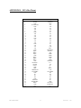
NEX-MCA
Users Manual
Including these Software Support packages:
MCA
Copyright © 2008 Nexus Technology, Inc. All rights reserved.
Contents of this publication may not be reproduced in any form without the written
permission of Nexus Technology, Inc.
Brand and product names used throughout this manual are the trademarks of their
respective holders.
MCA-MN-XXX
1
Doc. Rev. 1.10
Warranty Terms and License Agreement
For warranty terms, refer to the Terms and Conditions of Sale document that was included in the
product shipment. The Software License Agreement is displayed during installation. A hardcopy
of that agreement may be obtained from Nexus Technology.
All Nexus Technology products to which this manual refers are subject to the Terms and
Conditions of Sale document and the Software License Agreement, as appropriate.
Compliance with WEEE and RoHS Directives
This product is subject to European Union regulations on Waste Electrical and Electronics
Equipment. Return to Nexus Technology for recycle at end of life. Costs associated with the
return to Nexus Technology are the responsibility of the sender.
MCA-MN-XXX
2
Doc. Rev. 1.10
TABLE OF CONTENTS
1.0 OVERVIEW ........................................................................................................................... 4
1.1 General Information............................................................................................................ 4
2.0 SOFTWARE INSTALLATION ............................................................................................. 4
2.1 TLA700............................................................................................................................... 4
2.2 DAS9200............................................................................................................................. 5
3.0 CONFIGURING the NEX-MCA BUS ADAPTER ............................................................... 5
3.1 General Information............................................................................................................ 5
4.0 CONNECTING to the NEX-MCA ADAPTER...................................................................... 6
4.1 General................................................................................................................................ 6
4.2 TLA700............................................................................................................................... 6
4.3 92A96.................................................................................................................................. 6
5.0 CLOCK SELECTION ............................................................................................................ 8
5.1 General Information............................................................................................................ 8
6.0 VIEWING DATA ................................................................................................................... 8
6.1 Viewing State Data on the TLA700 ................................................................................... 8
6.2 Viewing Timing Data on the TLA700................................................................................ 8
6.3 Viewing State Data on the DAS9200/TLA500 .................................................................. 9
6.4 Viewing Timing Data on the DAS9200/TLA500............................................................... 9
APPENDIX A - Necessary Signals for Clocking ......................................................................... 10
APPENDIX B - Considerations.................................................................................................... 11
B.1 MCA Loading .................................................................................................................. 11
B.2 "Patch" Areas ................................................................................................................... 11
APPENDIX C - Modifying the NEX-MCA Adapter ................................................................... 12
APPENDIX D - MCA Bus Pinout................................................................................................ 13
APPENDIX E - References .......................................................................................................... 15
APPENDIX F - Support................................................................................................................ 16
TABLE OF TABLES
Table 1- NEX-MCA TLA700 / 92A96 Wiring .............................................................................. 7
Table 2- MCA BusOp Symbol Table ............................................................................................. 9
MCA-MN-XXX
3
Doc. Rev. 1.10
1.0 OVERVIEW
1.1 General Information
The NEX-MCA adapter has been designed to provide quick and easy connections to interface a
102- or 136-channel TLA700, a 92A96, or a 92C96 acquisition module to a MCA backplane.
(The MCA designation refers to the Micro Channel Architecture specification.) In addition, the
method of connection permits the use of other measurement devices such as oscilloscopes.
The included software will permit the acquisition of MCA bus cycles, and will display the data
in easy-to-read symbolic form rather than raw hexadecimal or binary data.
Please note that this manual uses some terms generically. For example, references to a 92A96
acquisition card apply to a 92C96 acquisition card; references to the DAS9200 apply equally to
the TLA500; and references to the TLA700 apply to a TLA704/714 or TLA711/720 chassis with
one or more 7L3/4 or 7M3/4 acquisition cards.
This manual assumes that the user is familiar with the MCA backplane specification and the
Tektronix TLA700, DAS9200, or TLA500 Logic Analyzer. Also, in the case of the TLA700, it
is expected that the user is familiar with Windows 95/98.
For information on using a Prism 32GPX/GPD module with this support, or if 5¼" DAS floppies
are needed, please contact Nexus Technology. See Appendix E for contact information.
2.0 SOFTWARE INSTALLATION
Two 3½” diskettes have been included with the NEX-MCA Bus Adapter. One is for use with the
TLA700 series, the other is to be used with a DAS9200 or TLA500.
2.1 TLA700
The MCA support software is loaded in the same method as other Win95/98 programs. Place the
NEX-MCA Install disk in the floppy drive of the TLA700. Select Control Panel and run
Add/Remove Programs, choose Install, Next, then Finish. Add/Remove will then run
SETUP.EXE on the floppy and install the support in its proper place on the hard disk.
To load a support into the TLA700, first select the desired Logic Analyzer card in the Setup
screen, select Load Support Package from the File pull-down, then choose MCA and click on
Okay. Note that for either support the Logic Analyzer card must be at least 102-channels in
width.
MCA-MN-XXX
4
Doc. Rev. 1.10
2.2 DAS9200
The included diskette should be loaded onto the DAS9200 using the Install Application
function. This function is available from the Disk Services menu of the DAS. For more
information, refer to the Tektronix DAS9200 or TLA500 System User's Manual.
Load the desired support from within the 92A96 Config menu by choosing "MCA Support” and
pressing <RETURN>. The channel grouping, clocking and symbols will then be loaded.
3.0 CONFIGURING the NEX-MCA BUS ADAPTER
3.1 General Information
The number of signals defined by the Micro Channel specification exceeds the channel count of
a 92A96, or 102-channel TLA. Because of this, three jumper blocks have been defined - JP2,
JP3, and JP4. By placing a shorting jumper across the pair of pins next to the desired signal
name, that signal can then be monitored during the acquisition. For information on physically
modifying the NEX-MCA adapter to monitor signals not provided with the standard
implementation, refer to Appendix C.
JP2 is used to select between SDSTRB~ and the derived signal DSDSTRB~. For proper clocking
of Streaming Data activity the jumper should be set for DSDSTRB~ (connecting pins 2 and 3,
the leftmost two pins). For high speed timing purposes, it may be desired to view the actual
SDSTRB~ signal. In these cases, the jumper should be placed between pins 1 and 2, the
rightmost two pins.
JP3 selects between CHRESET and SDCLK. To monitor CHRESET the jumper should connect
pins 1 and 2 (the rightmost two). Placing the jumper between pins 2 and 3 (the leftmost pair) will
permit monitoring the SDCLK signal.
JP4 is used to select which IRQ line should be monitored. Using the jumper, short the two pins
adjacent to the desired IRQ signal.
MCA-MN-XXX
5
Doc. Rev. 1.10
4.0 CONNECTING to the NEX-MCA ADAPTER
4.1 General
Although taller than a standard Micro Channel module, the NEX-MCA adapter is designed to
plug directly into any Micro Channel backplane slot. The board length and connector spacing
conforms to Micro Channel specifications.
4.2 TLA700
When using NEX-MCA support with a TLA700 containing a 7L3/4 or 7M3/4 acquisition
module, the necessary acquisition data sections are A0-A3, D0-D3, and C0-C3. These grouped
channels (8 podlets to a group) should be connected to the locations denoted for the A96. Follow
the silk-screened information on the board that shows the proper relationship between the signal
and reference inputs. When properly connected, the sides of the podlets that have writing on
them should be visible.
Connect the four clock leads to their specified locations at J12 (the only connector with 4
locations). Again, follow the silk-screened information to properly connect the clock input and
its ground. Table 1 shows the wiring and Channel Grouping for the TLA700 when used with the
NEX-MCA adapter.
4.3 92A96
When using a 92A96, connect the grouped pods (8 podlets to a group) to their appropriate
locations by following the silkscreen information printed on the adapter board. The 92A96 pods
are labeled A0-A3, D0-D3, and C0-C3. Each pod has its proper location denoted on the
silkscreen of the adapter board. When attaching the pods, follow the silkscreen information on
the board showing the ground and signal pin locations. When properly connected, the colored
sides of the podlets should be visible.
Connect the four clock leads (one per A96 cable) to their specified locations at J16 (the only
connector with 4 locations). Again, follow the silkscreened information to properly connect the
clock input and its ground. Table 1 shows the wiring and Channel Grouping for the 92A96.
MCA-MN-XXX
6
Doc. Rev. 1.10
Group
Name
Address
(Hex)
BusOp
(Sym
BusSize
(Hex)
Clocks
Signal
Name
A31
A30
A29
A28
A27
A26
A25
A24
A23
A22
A21
A20
A19
A18
A17
A16
A15
A14
A13
A12
A11
A10
A9
A8
A7
A6
A5
A4
A3
A2
A1
A0
TC~
MSDR~
SDR1~
SDR0~
REFRESH~
DSDSTRB~
M/IO~
S1~
S0~
TR32
DS32RTN~
DS16RTN~
BE3~
BE2~
BE1~
BE0~
CMD~
MSDR~
MCA
Pin #
B86
B85
B84
A84
A83
A82
B82
B81
B06
B07
B08
B10
B11
B12
B14
B15
B16
B18
B19
B20
A04
A05
A06
A08
A09
A10
A12
A13
A14
A16
A17
A18
A30
B62
B61
B44
A45
*
A34
A33
A32
B80
A79
A44
A78
B78
B77
B76
B34
B62
TLA700 / 92A96
input
A3:7
A3:6
A3:5
A3:4
A3:3
A3:2
A3:1
A3:0
A2:7
A2:6
A2:5
A2:4
A2:3
A2:2
A2:1
A2:0
A1:7
A1:6
A1:5
A1:4
A1:3
A1:2
A1:1
A1:0
A0:7
A0:6
A0:5
A0:4
A0:3
A0:2
A0:1
A0:0
C0:1
C3:3
C2:3
C2:2
C2:5
C2:0
C0:0
C3:5
C3:4
C0:4
C0:7
C0:6
C1:3
C1:2
C1:1
C1:0
CLK0
CLK2
Group
Name
Data
(Hex)
Misc
(Hex)
Arb
(Hex)
Clocks
Signal
Name
D31
D30
D29
D28
D27
D26
D25
D24
D23
D22
D21
D20
D19
D18
D17
D16
D15
D14
D13
D12
D11
D10
D9
D8
D7
D6
D5
D4
D3
D2
D1
D0
IRQn~
SFDBKRT~
CHCK~
RST/SDCK
MADE24
SBHE~
CHRDYRTN
ADL~
CMD~
BURST~
PREEMPT~
ARB/GNT~
ARB3
ARB2
ARB1
ARB0
SDCLK
unused
MCA
Pin #
A75
A74
B74
B73
B72
A72
A71
A70
B69
B68
A68
A67
A66
B66
B65
B64
B53
B52
B51
A51
A50
A49
B49
B48
A42
A41
A40
B40
B39
A38
B38
A37
--A64
B32
--A02
A54
B35
A20
B34
A22
A21
--A28
A26
A25
A24
*
TLA700 / 92A96
input
D3:7
D3:6
D3:5
D3:4
D3:3
D3:2
D3:1
D3:0
D2:7
D2:6
D2:5
D2:4
D2:3
D2:2
D2:1
D2:0
D1:7
D1:6
D1:5
D1:4
D1:3
D1:2
D1:1
D1:0
D0:7
D0:6
D0:5
D0:4
D0:3
D0:2
D0:1
D0:0
C2:6
C0:5
C3:6
C3:7
C0:3
C3:0
C2:1
C2:4
C2:7
C0:2
C3:2
C3:1
C1:7
C1:6
C1:5
C1:4
CLK1
CLK3
Table 1- NEX-MCA TLA700 / 92A96 Wiring
* Derived signal
MCA-MN-XXX
7
Doc. Rev. 1.10
5.0 CLOCK SELECTION
5.1 General Information
All Micro Channel data is acquired using either both edges of CMD~ (for standard cycles) or a
combination of CMD~ and the synthesized SDCLK (for Streaming Data cycles). The circuitry
on the NEX-MCA Bus Adapter is used to provide the necessary clock edges at the necessary
times for properly acquiring Streaming Data cycles.
6.0 VIEWING DATA
6.1 Viewing State Data on the TLA700
After making an initial acquisition, the TLA700 will display the data in the Listing (State)
format.
Address and Data information are displayed as hexadecimal values; Bus Operation data is
displayed using symbols; Miscellaneous, Bus Size, and the Arbitration signal groups are all
displayed in hexadecimal radix.
The use of Symbol Tables when displaying state data enables the user to quickly determine what
type of bus cycle was acquired. One symbol table (Table 2) has been provided to show the type
of transaction that occurred on the MCA bus, and its filename is "MCA_BUS.TSF". This symbol
table quickly shows whether the acquisition was of a memory or I/O operation, whether it was a
read or a write, etc.
It is important to note that changing the group, channel, or wiring of the Bus Operation group
can result in incorrect symbol information being displayed.
6.2 Viewing Timing Data on the TLA700
By default, the TLA700 will display an acquisition in the Listing (State) mode. However, the
same data can be displayed in Timing form by adding a Waveform Display window. This is done
by clicking on the Window pull-down, selecting New Data Window, clicking on Waveform
Window Type, then choosing the Data Source. Two choices are presented: MCA and MCAMagniVu. The first (MCA) will show the exact same data (same acquisition mode) as that shown
in the Listing window, except in Timing format. The second selection, MCA-MagniVu, will
show all of the channels in 2GHz MagniVu mode, so that edge relationships can be examined at
the module’s trigger point. With either selection, all channels can be viewed by scrolling down
the window. Refer to the TLA700 System User’s Manual for additional information on
formatting the Waveform display.
MCA-MN-XXX
8
Doc. Rev. 1.10
Pattern
xx0xxxx
0x1xxxx
101x101
101x110
111xx11
111x101
111x110
111xx00
111x001
111x010
TLA700 / 92A96
Symbol
Refresh
Reserved
StrmngDataMemRead
StrmngDataMemWrite
Inactive
Memory Read
Memory Write
Reserved
I/O Read
I/O Write
Table 2- MCA BusOp Symbol Table
Signals, from left to right:
TC~, MSDR~, SDR1~, SDR0~, REFRESH~, DSDSTRB~, M/IO~, S1~, S0~
6.3 Viewing State Data on the DAS9200/TLA500
After an acquisition is made the DAS9200 Logic Analyzer will display the data in State Display
mode (as a default only). Address and Data information are displayed as hexadecimal values;
Bus Operation data is displayed using symbols; Miscellaneous, Bus Size, and the Arbitration
signal groups are all displayed in hexadecimal radix.
The use of Symbol Tables when displaying state data enables the user to quickly determine what
type of bus cycle was acquired. One symbol table (Table 2) has been provided to show the type
of transaction that occurred on the MCA bus, and its filename is "MCA_BUS". This symbol
table quickly shows whether the acquisition was of a memory or I/O operation, whether it was a
read or a write, etc.
It is important to note that changing the group, channel, or wiring of the Bus Operation group
can result in incorrect symbol information being displayed.
6.4 Viewing Timing Data on the DAS9200/TLA500
It may be useful to display acquired information using the Timing Diagram display of the
DAS9200. (Note that, unlike some other logic analyzers, with the DAS9200 there is no need to
re-acquire MCA data when changing from one display mode to another. The same data can be
viewed in either format.) This method of data display can be particularly useful when an
asynchronous acquisition has been made (using the DAS9200 internal acquisition clock) to
determine the relationships between signal edges.
Refer to the appropriate Tektronix DAS 92A96 Module User's Manual for more detailed
information on formatting the display of the acquired data.
MCA-MN-XXX
9
Doc. Rev. 1.10
APPENDIX A - Necessary Signals for Clocking
To properly acquire Micro Channel backplane activity, the following signals must be provided:
CMD~, MSDR~, CHRDYRTN, SDR1~, SDR0~, and SDSTROBE~. However, SDSTROBE~ is
only necessary when Streaming Data cycles are to be monitored.
For all but Streaming Data cycles, Address information is acquired on the falling edge of CMD~,
and the Data bus is acquired on the rising edge of CMD~. The other signals (MSDR~,
CHRDYRTN, SDR1~, and SDR0~) are used as clocking qualifiers, or as cycle type
determinants.
In order to properly acquire Streaming Data bus cycles some circuitry had to be added to the
NEX-MCA adapter. This circuitry generates the SDCLK and DSDSTRB~ signals used by the
logic analyzer card to properly acquire these cycles. These signals DO NOT exist on the MCA
backplane.
MCA-MN-XXX
10
Doc. Rev. 1.10
APPENDIX B - Considerations
B.1 MCA Loading
It must be noted that the NEX-MCA Bus Adapter does not provide any buffering of the MCA
backplane signals. This was a conscious design decision that was made by balancing the
tradeoffs of possible backplane loading versus signal acquisition accuracy. By not introducing
signal buffers it is possible, using the NEX-MCA adapter, to see the exact timing relationships
and signal waveforms from the backplane. It is believed that the signal loading of the TLA700 or
92A96 acquisition cards is low enough so that MCA signal degradation will not occur.
The NEX-MCA Adapter Board was designed so that the run lengths for critical signals (and
those with the highest activity levels, such as the address / data bus) are as short as possible. This
should help greatly in retaining signal integrity.
B.2 "Patch" Areas
If signal loading or reflection does become a concern, the capability exists to add series resistors
to any MCA signal. Patch areas have been provided next to each TLA700/A96 connector,
consisting of two rows of plated through holes. These areas (outlined on the silk-screen and
labeled as Nxx) are suitable for individual resistors or resistor networks. To add a series resistor,
simply cut the trace of the desired signal on the component side of the board, and solder the
resistor between the two feed-throughs.
MCA-MN-XXX
11
Doc. Rev. 1.10
APPENDIX C - Modifying the NEX-MCA Adapter
As previously mentioned, the Micro Channel specification has too many signals to be able to
acquire them all with just one 92A96 or 102-channel TLA acquisition card. Assumptions have
been made as to what signals are of interest, but these assumptions may not be appropriate for
every instance. For these occasions, the NEX-MCA adapter may be easily modified to monitor
any desired signals.
All MCA signals have been brought out to feed-throughs on the board, and there are three
unused TLA/A96 connectors on the board (J4, J8, and J20). These connectors each have a series
of holes beneath them (towards the edge connector) to provide easy solder points. Use wire wrap
wire to connect the Micro Channel signals to these connectors.
When changing the signals connected to an A96 pod, the channel grouping default in the
TLA700/DAS 9200 will have to be changed appropriately. Refer to the TLA70 or DAS 9200
manuals for information on this procedure. Also note that if any of the signals to the MCA
BusOp group are changed then the included Symbol Table will no longer be accurate.
MCA-MN-XXX
12
Doc. Rev. 1.10
APPENDIX D - MCA Bus Pinout
Pin #
1
2
3
4
5
6
7
8
9
10
11
12
13
14
15
16
17
18
19
20
21
22
23
24
25
26
27
28
29
30
31
32
33
34
35
36
37
38
39
40
41
42
43
44
45
46
MCA-MN-XXX
Row B - Solder Side
AUDIO GND
AUDIO
GND
14.3MHz OSC
GND
A23
A22
A21
GND
A20
A19
A18
GND
A17
A16
A15
GND
A14
A13
A12
GND
IRQ9~
IRQ3~
IRQ4~
GND
IRQ5~
IRQ6~
IRQ7~
GND
DPAREN~
DPAR0
CHCK~
GND
CMD~
CHRDYRTN
CD SFDBK~
GND
D1
D3
D4
GND
CHRESET
SDSTROBE~
SDR0~
GND
Key
13
Row A - Component Side
CD SETUP~
MADE24
GND
A11
A10
A9
+5V
A8
A7
A6
+5V
A5
A4
A3
+5V
A2
A1
A0
+12V
ADL~
PREEMPT~
BURST~
-12V
ARB0
ARB1
ARB2
-12V
ARB3
ARB/GNT~
TC~
+5V
S0~
S1~
M/IO~
+12V
CD CHRDY
D0
D2
+5V
D5
D6
D7
GND
DS16RTN~
REFRESH~
key
Doc. Rev. 1.10
MCA-MN-XXX
Pin #
47
48
49
50
51
52
53
54
55
56
57
58
Row B - Solder Side
Key
D8
D9
GND
D12
D14
D15
GND
IRQ10~
IRQ11~
IRQ12~
GND
Row A - Component Side
key
+5V
D10
D11
D13
+12V
DPAR1
SBHE~
CD DS16~
+5V
IRQ14~
IRQ15~
Pin #
59
60
61
62
63
64
65
66
67
68
69
70
71
72
73
74
75
76
77
78
79
80
81
82
83
84
85
86
87
88
89
Row B - Solder Side
Reserved
Reserved
SDR1~
MSDR~
GND
D16
D17
D18
GND
D22
D23
DPAR2
GND
D27
D28
D29
GND
BE0~
BE1~
BE2~
GND
TR32
A24
A25
GND
A29
A30
A31
GND
APAR2
APAR3
Row A - Component Side
Reserved
Reserved
GND
Reserved
Reserved
SFDBKRTN~
+12V
D19
D20
D21
+5V
D24
D25
D26
+5V
D30
D31
DPAR3
+12V
BE3~
DS32RTN~
CD DS32~
+5V
A26
A27
A28
+5V
APAREN~
APAR0
APAR1
GND
14
Doc. Rev. 1.10
APPENDIX E - References
Tektronix TLA700 System User’s Manual
Tektronix TLA700 Logic Analyzer User’s Manual
Tektronix DAS9200 / TLA500 System User’s Manual
Tektronix 92A96 / 92C96 Module User’s Manual
"The IBM PS/2 Hardware Interface Technical Reference"
published by IBM, P/N S68X-2330-00
November 1989
"The Micro Channel Architecture Handbook"
by Chet Heath and Winn L. Rosch
published by Brady
ISBN 0-13-583493-7
MCA-MN-XXX
15
Doc. Rev. 1.10
APPENDIX F - Support
About Nexus Technology, Inc.
Established in 1991, Nexus Technology, Inc. is dedicated to developing, marketing, and
supporting Bus Analysis applications for Tektronix Logic Analyzers.
We can be reached at:
Nexus Technology, Inc.
78 Northeastern Blvd. #2
Nashua, NH 03062
TEL: 877-595-8116
FAX: 877-595-8118
Web site: http://www.nexustechnology.com
Support Contact Information
Technical Support
General Information
Quote Requests
[email protected]
[email protected]
[email protected]
We will try to respond within one business day.
If Problems Are Found
Document the problem and e-mail the information to us. If at all possible please forward
a Saved System Setup (with acquired data) that shows the problem. Do not send a text
listing alone as that does not contain enough data for analysis. To prevent corruption
during the mailing process it is strongly suggested that the Setup be zipped before
transmission.
MCA-MN-XXX
16
Doc. Rev. 1.10