1
EasyLoader
AV-3044 LED
AV-3044 GSM
(for LED keypads)
Integrated Alarm Control panel &
Communicator 4 or 8 zones
SMS & DTMF Enabled
Installation and Operation Large Manual
Version 1.09
Edition I
This product is subject to continuous enhancements and therefore
specifications may be changed or altered without prior notice
Item: 4785E_LED (A3BKE)
Rev 02: 03-NOV-2013
1
Table of contents
Introduction series AV-3044 LED ................................................................................................... 3
Tips to first time installer................................................................................................................. 3
Revision changes ........................................................................................................................... 4
Keypad AV-702 short description ................................................................................................... 4
2. Wiring devices to the panel ........................................................................................................................... 6
2.1 Zone Wiring.............................................................................................................................. 6
2.2 AV-3044 Eight Zone Panel Zone Wiring .................................................................................. 7
2.3 Keypad Wiring .......................................................................................................................... 8
2.4 Siren Wiring.............................................................................................................................. 9
2.5 Remote Indication Terminals.................................................................................................... 10
2.6 Remote Indications Testing ...................................................................................................... 11
2.7 Grounding Wiring & Lightning Protection ................................................................................. 11
2.8 Back-Up Battery ....................................................................................................................... 11
3. Telephone Line and Central Station .............................................................................................................. 12
3.1 Telephone Line & GSM Wiring ................................................................................................. 12
3.2 SVM – Synthesized Voice Module ........................................................................................... 13
3.3 Answering Machine Bypass ..................................................................................................... 13
3.4 Telephone Line Test................................................................................................................. 13
3.5 Contact ID Format .................................................................................................................... 13
3.6 ID Codes for Communicator ..................................................................................................... 14
3.7 Remote Up and Download ....................................................................................................... 14
4. Remote DTMF and remote Arming................................................................................................................ 15
4.1 Remote Key and Wireless Arming & Disarming....................................................................... 15
4.2 Remote Access via DTMF........................................................................................................ 16
4.3 DTMF Commands .................................................................................................................... 17
5. System Codes ............................................................................................................................................... 18
5.1 Description of main codes ........................................................................................................ 18
5.2 Set New User Code.................................................................................................................. 18
5.3 Installer Programming mode & Code change .......................................................................... 19
5.5 Restore default codes .............................................................................................................. 19
5.6 Auto Arming.............................................................................................................................. 19
6. LED Keypad .................................................................................................................................................. 20
6.1 Hold-Down Functions ............................................................................................................... 20
6.2 Group Bypass (home mode) .................................................................................................... 22
6.4 LED Dual Keys Hold Down Functions ...................................................................................... 24
6.5 Keypad Functions at location 200 ............................................................................................ 24
6.6 Keypad Sounder....................................................................................................................... 26
6.7 LED Indicators .......................................................................................................................... 26
7. New address at series 3000 .......................................................................................................................... 28
7.1 Systems parameters address................................................................................................... 28
7.2 Telephone and SMS address ................................................................................................... 29
7.3 Events reported by the SMS module ........................................................................................ 29
7.4 Dialer reporting Programming locations ................................................................................... 32
8. Programming Sheet Version 1.08 LED ......................................................................................................... 33
9. Powering Up & Wiring Diagram..................................................................................................................... 38
9.1 Before Powering Up ................................................................................................................. 38
9.2 Technical Specifications AV-3044............................................................................................ 39
9.3 Wiring Diagram ........................................................................................................................ 40
2
Introduction series AV-3044 LED
This is a full manual for series 3000 alarm panels supplied as reference (not with panel).
AV-3044 LED is compatible with Av-Gad 7 segments LED keypads (AV-701, AV-702).
AV-3044 LED is 4 zones or expandable to 8 zones by using end of line resistors, 4 or 8 zones
mode is set via programming.
Series 3000 communication and dialing options are by far improved compared to series 2000:
Dials to four phone numbers. GSM option available, item AV-3044 GSM
Dials and reports to two different central stations
Sends SMS messages via PSTN (saves the SIM card and GSM fee) to four numbers
Signal test to central station in few modes
Set the panel to 4 or 8 zones mode via address 200 commands
Added special outdoor detectors zone, named Pulse count zone
DTMF remote control arming, disarming and more (not valid in AV-3044 GSM)
The AV-3044 LED alarm and events sent by SMS without particular SMS programming.
Examples: "Zone 1" during alarm the SMS received by user quoted as "Zone 1", or if low battery
detected “Low Battery” SMS is transmitted. SMS selection is optional.
Series 3000 been revised for higher security when using remote PC (PC software not support
this type yet) and remote DTMF in order to prevent criminal system tampering. Pay attention to
new default settings.
Tips to first time installer
If you are a first time installer, do not hook up any remote sensors at first. The most common
confusion comes about when the alarm will refuse to arm, because a zone is “troubled”.
Complete the power supply, siren, keypad and strobe wiring, and for the moment connect ALL
the zone terminals to –V, (by default panel is 4 zones).
Programming is done via keypad, fast and simple.
This will simulate a system with all zones looped out through closed switches. The alarm is
supplied already programmed with an “average” list of settings (default) and can be used straight
away, a few of the program locations may have to be changed to suit the actual sensors and
output devices used. The AV-3044 supports LED keypads (AV-701, AV-702) only.
Read this manual carefully, it looks complicated, but all the information is there
Do not power up with battery! Use the AC power for start and testing
To start with: Hook up the keypad, connect all zones to –V or apply resistors for 8 zone mode, power-up by
applying AC only
In case the keypad displays ‘8’ and keys not respond verify the minus (-V) wire and other keypad connection
Arm and disarm the system, when the Status LED light (not blinking), enter your master code; 1234
Try the hold-down functions. Hold each key for approximately 2 seconds
Set the system time by holding-down key ‘0’ then ‘1’, set time in 24H format, blinking ‘Set Time’ stop
The default programming is set for siren alarm device that requires 12V to alarm (Bell Mode)
System dialer is noisy? You need ADSL filter. Check if the PSTN line carry ADSL signals
Make sure you are using the Earth terminal
for Grounding; it is not a minus terminal
Typing six erroneous codes will lock the keypad keys for 30 seconds
Fast test: Verify “Dial LED" Self Test at Initialization (STI) - Blinks for the first 50 seconds after power on,
confirms panel is operative, from keypad wait to six beeps to confirm communication OK.
3
Revision changes
Date
11 April 2012
11 April 2012
12 May 2012
12 May 2012
12 May 2012
22 July 2012
22 Nov 2012, Dec 11,
2012
Version
1.05
1.05
1.06
1.06
1.06
1.07
1.08-1.09
Contains
4 numbers for SMS, 4 numbers for PSTN dial
Add address 097; SMS sending trials
select 4 or 8 zone via address 200
Added Pulse count zones for outdoor detectors
Contact ID is default for CS report
Add GSM version. 057 for open/close report. See app. AV-3044 GSM
Add address 003 for periodic tests. In GSM mode dial via PSTN. SMS
via LINE or GSM. Can dial and communicate to Central station via LINE and
transmit SMS and Dial mode either via LINE or GSM, Hebrew or English.
Address 053-057 added.
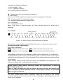
Keypad AV-702 short description
Figure 1: AV-702 LED keypad-Hold down functions
Common Terms in this Manual
‘SHUNT‘ and ‘BYPASS’ are interchangeable terms
Program Mode - Enables features programming. In Programming mode alarm is
disabled
Use Mode – System is disarmed and not in alarm or program mode
AV-701 and/or AV-702 is identical in operation
4
Standard Keypad functions are accessed by pressing keys (short press). The 1 to 0
keys used for Arming/Disarming (ON/OFF), Zone Shunt (Bypass) and other
programming functions.
For test & display purposes hold down the key. Example: siren test hold down key1
A short beep confirms each key press.
A short press on keypad key accesses the following special functions:
Chime
5
Shunt
0
Instant Arming, by pressing key ‘5’ (requires programming).
Zone Bypass, by pressing key ‘0,’ followed by entering the Zone number/s
Group Bypass explained in the keypad section.
For full details refer to the keypad section in this manual and the LED keypad manual.
Electronic Fuse Overview
The Electronic Fuse device included as a series element in electric circuit. In response to an over current it
protects the circuit by going from a low-resistance to a high-resistance state that reduces the current to a level
that’s safe for the circuit elements. The change in resistance is the result of a rapid increase in the temperature
of the device. Like traditional fuses, Electronic Fuse devices interrupt the flow of dangerously high current.
However, unlike traditional fuses, they automatically reset after the fault cleared and power to the circuit
removed. Because they are solid-state, Electronic Fuses are also better able to withstand mechanical shock and
vibration, and provide reliable protection in a wide variety of applications. In case of over current, carefully touch
the fuse body (yellow round disc), hot body means the Electronic Fuse in protection mode, disconnect the load
and wait 2-3 minutes until the fuse body get cooler.
5
2. WIRING DEVICES TO THE PANEL
2.1 Zone Wiring
Your system provides few ways of zone wiring: None EOL resistor loop, EOL resistor
loop. The EOL loop protects the zone lines against tampering. It’s recommended to use
the EOL mode; it’s safer and keeps lower EMI and RFI interference.
Figure 2.1: None EOL mode zone wir ing
Via programming, select either End-Of-Line (EOL) resistor protection available only at
four zone mode, or non-EOL mode. The EOL is defined at address 029; the default
program is set at non-EOL for all zones. To select EOL mode enter at address 029 the
required zone to be EOL, or enter ‘0’ to enable all zones as EOL.
Note: Address 029 at the AV-3044 8 zone mode is blocked. Only EOL mode is available.
If EOL mode is selected install the EOL resistor (2.2K/0.25 or 0.5W) inside the detection
device (e.g. PIR, Magnetic Switch).
Figure 2.2: EOL mode zone wiring (in four zone mode)
Maximum zone wiring length is 200 meters using 0.5-mm2 wires, EOL mode wiring is
highly recommended.
Note: ‘Zone’ and ‘Sector’ are interchangeable terms in this manual.
Always use EOL resistor, to prevents EMI and RFI interference and higher security
6
An EOL zone will report Tamper alarm in case of zone shorting (if it has been EOL
programmed). For connecting N.O. zones, programming is required, refer to address
042. Do not connect few sensors to one zone in EOL mode.
2.2 AV-3044 Eight Zone Panel Zone Wiring
The AV-3044 LED board carries a specific identification label (refer to wiring diagram)
that shows the version and panel type.
The AV-3044 works in 4 or 8 zone mode according to your setting, if 8 zones selected
EOL mode is a must (can’t work in none EOL), it means always using EOL resistors.
The zones are referred to –V. Connect two wires to the same terminal, one wire in series
with the 2.2.K resistor and the sensor contacts (relay), the other wire in series with 4.7K
resistor and other contacts.
Tamper alarm per zone is not available with AV-3044 LED in 8 zone mode.
Colors
4.7K
Yellow
Purple
Red
Av-Gad 3000
Series panel
Colors
2.2K
Red
Red
Red
-V
Z1
2.2K
4.7K
Eye-Spy II
PIR
Notice wires to -V
Figure 2.3: EOL mode zone wiring (in four z one mode)
The 2.2K resistors are wired with the odd zones (1, 3, 5, 7), the 4.7K are wired with the
even zones (2, 4, 6, 8) as table below shows, for latest AV-3048 starting version 1.05.
Terminal wire No.
1
2
3
4
Resistor 2.2K
Zone No. 1
Zone No. 3
Zone No. 5
Zone No. 7
Resistor 4.7K
Zone No. 2
Zone No. 4
Zone No. 6
Zone No. 8
For testing eight zones mode connect resistors as shown in figure 2.4.
7
Figure 2.4: Resistors doubling mode zone wiring (in eight zone mode)
2.3 Keypad Wiring
Up to three AV-701 or AV-702 Keypads can be connected to AV-3044 Control Panel.
When few keypads are connected, wire each one directly to the panel, not from one
keypad to the other. Refer to drawing in next page.
When using few keypads connect them in parallel. Each keypad has four terminal wires:
(+) Power, connect to + Aux. Power System Data, connect to OR
(–) Power, connect to – Aux. Power System Strobe, connect to YE
Av-Gad
Panel
AV-GAD
ARMED
Don’t wire from one keypad to
the other than to panel
AV-GAD
EASYLOADER AV-701
STATUS
SHUNT
Av-Gad
Panel
ZONE
DISPLAY
FIRE
ARMED
Siren
1
Shunt
Display
2
Status
Delay
Delete
4
Chime
5
Telephone
Test
7
Program
8
Reset
*
Shunt
0
AV-GAD
EASYLOADER AV-701
STATUS
SHUNT
ZONE
DISPLAY
FIRE
ARMED
ARMED
1
Shunt
Display
2
Status
Delay
Delete
4
Chime
5
Telephone
9
Test
7
Program
8
Reset
*
Shunt
Shunt
Display
2
Status
4
Chime
5
Telephone
9
Test
7
Program
8
Reset
0
ZONE
DISPLAY
FIRE
Siren
1
Delay
Delete
Shunt
SHUNT
6
Siren
6
*
AV-GAD
EASYLOADER AV-701
STATUS
3
3
#
Wire each keypad to the
panel
#
Wrong wiring
0
EASYLOADER AV-701
STATUS
SHUNT
ZONE
DISPLAY
FIRE
3
Siren
1
Shunt
Display
2
Status
6
Delay
Delete
4
Chime
5
Telephone
9
Test
7
Program
8
Reset
*
Shunt
#
0
3
6
9
#
Correct wiring
Figure 2.5: W iring more than one keypad
Wire length for each Keypad should not exceed 100 meters (when using 0.5 mm 2
wires).
For longer than 100 meters keypad wiring, contact manufacturer's consultant.
For AV-701/702TP (keypad with tamper) run five (5) wires. Connect the TMP terminal to
a 24H or Tamper zone.
Power at Keypad should be a minimum of 11.5 Volts.
8
IMPORTANT! Never run Keypad wires alongside telephone wires, high voltage
wires, or transmitting antennae. Wire the keypad wires separately and not in same
cable with other devices (telephone, PIR etc.)
For proper connection, refer to wiring diagrams at the end of the manual.
Figure 2.6: W iring keypad to control panel
2.4 Siren Wiring
The control panel contains single siren outputs, protected by Electronic Fuse.
Siren should be outdoor type with a 12V DC, 1A or optional (requires programming)
speaker siren with minimum power of 15W, 8 Ohms Impedance.
Enclose the siren in a metal housing, with anti-tamper switch protection.
Figure 2.7: W iring sirens to control panel
9
Warning, siren/s current should not exceed 1.0 Ampere
Bell mode is factory default; in Bell mode install a 12V DC siren, which contains sound
driver or electronic modules.
The alarm issued by the siren differs according to the type of zone.
Bell Mode’ converts Siren outputs into 13.6V DC outputs (no sound is issued).
Bell mode is applicable for driving self-powered sirens or bells, or combined sirens and
strobes.
13.6V DC is issued at Bell mode. It’s recommended to use Bella sirens series.
In Bell mode, connect only sirens, which contain sound driver or electronic modules.
Self contain Bell mode is programmable (address 072-1 and 073-3). This mode provides
connection of Bells or Sirens that requires 13.6V at idle and 0V during alarm.
Contact manufacturer's consultant before connecting higher power loads.
To connect self-contained sirens, Bells, and inner-oscillating sirens, Bella siren series
refer to address 072-1 for Bell mode. Bella sirens support internal battery charge and
monitor for higher security.
For higher security it’s recommended to have internal and external siren, see below
drawing.
Siren configuration programming address
Address
070-1
072-1
073-3
073-6
063, 064,
065
Feature
Siren beep upon arming
Bell mode
Self contained siren
Siren 3 peeps at disarming
Siren duration times
Explanation
Sounds a short beep to indicate arming
Send 12V DC to drive the siren
Send 12V at idle, drop to zero V at alarm
Sounds 3 short beeps to indicate disarming
Configures the siren times
2.5 Remote Indication Terminals
Indication
Application
ON
(-V) on closing (Arming) or if cross-zoning feature selected
A1
(-V) during alarm from the programmed zone
The A1 may be used to drive a low current Strobe Light (Xenon) that consumes up to
300 mA.
Home Automation feature: Momentary activation of A1 output for three seconds, via any
DTMF telephone command (address 074-2). See drawing sample.
In case other features are selected for the same output, this feature is not applicable.
Figure 2.8: W iring remote indication output to a relay
10
2.6 Remote Indications Testing
To test the remote indication outputs without entering to alarm mode; enter to
programming mode (hold down 8, enter 1994, followed by #).
Testing ON output, enter 200 than 30 to enable, 200 than 31 to disable
Testing A1 output, enter 200 than 32 to enable, 200 than 33 to disable
To quit programming mode enter 999 than #.
2.7 Grounding Wiring & Lightning Protection
The control panel must be earth grounded for lightning protection to work effectively, and
in order to prevent RFI and EMI interferences. Connect the ground to a verified coldwater pipe using a minimum 16 AWG (or larger) wire. Run the wire via the shortest
possible route.
Syst em grounding is compulsory
Note: Connect the Ground wire, to the
terminal. This is not a minus (-V).
Be careful of static discharge; before handling the main board touch a grounded metal surface to
discharge.
Before grounding the system, make sure to connect ground properly, check that ground
does not transfer high voltages.
2.8 Back-Up Battery
Make sure to connect the Battery in the correct polarity!
The system's Red wire is the positive pole (+) and the Black wire is the negative pole (-).
The battery will provide power back up in case of AC power failure.
Connect back-up battery to ensure proper operation of the system.
Recommended battery: 7 Amperes per Hour (AH), 12V (sealed lead acid) type.
A 7.2 AH battery backs up the control panel and a single keypad for approximately 8
hours.
Series 3000 panels accommodates a battery of up to 12V – 7.2 AH (max.).
An Electronic Fuse rated at 2.5A protects the battery.
Add a power supply for installation with over three LED keypad and/or if over ten
high current sensors included. Refer to Av-Gad AV-21, AV-40 power supply and
charger.
The 4AH–12V battery fits in the ABS box, but the door is too tight, why? Note the
following:
1. Notice two small bulges on the ABS box door designed for supposing and hold
the battery may displace the battery; place the battery between the bulge and not
on it
2. Make sure that the battery is not laying on the income wiring
11
3. TELEPHONE LINE AND CENTRAL STATION
3.1 Telephone Line & GSM Wiring
Dialing sequence: 1st dials to central stations, 2nd send SMS, 3rd dials to standard
phones (wired or mobile). If central station not programmed sequence is bypass.
B
E
+
+
R57
VA6
+
VA4
R44
Q12
R59
+
C
B
E
VA1
SVM IN
E
B
C
B
E
It’s recommended to connect the control panel to an independent telephone line, if other
device is in parallel with the alarm panel, this may grab the call first (like a message
answer/fax) during remote up and download and remote DTMF. Don’t connect fax or
answering machine in parallel on the same telephone line.
In AV-3044 GSM if phone numbers programmed system dials them via PSTN, send
SMS via GSM.
Default dialing mode is DTMF. At areas with low quality PSTN Pulse Dial (old dialing
format) is optional, at Pulse Dial mode the default is European Make/Break rate of 40/60
milliseconds (in Pulse dialing). For Australia: Enable 074-8 (echo cancellation), order
with AS suffix (AUSTEL approved).
Figure 3.1: W iring Telephone (PSTN) Line
Dialing mode is programmable (refer to programming sheet addresses 084).
Connect the telephone line to ‘TEL-LINE’ terminal, if handsets connected to same line
connect them to ‘PHONES’, when system attempts to dial the ‘PHONES’ is
disconnected.
Do not connect to ISDN or other digital telephone system. Most ISDN converters contain
an Analog line; connect the Analog line of the ISDN to the panel TEL-LINE terminal.
If the PSTN is DSL/ADSL type connect a dedicated lien filter supplied by local Telecom
Company, or Av-Gad AV03 high end ADSL filter.
If GSM module is required: Use high end unit like AVG-15, AVG-16. Cut the jumper at
the PCB, located at the right-lower side of the PCB, see drawing at wiring diagram.
To delete a tel. number: In programming, enter address (like 010), hold down key 9.
Consider that low quality GSM module cause great problems like wrong dialing, RF
interferences, wrong reporting to central station and disables the DTMF remote control
feature.
12
3.2 SVM – Synthesized Voice Module
The SVM-40 Synthesized Voice Modules (SVM) is optional (not supplied with the panel).
The SVM allows the recording and playback of two messages, with optional playback
through an external speaker (not included) or via the phone during alarm.
SVM-40 message duration is 40 seconds. The SVM contains an on board microphone.
The SVM is a high technology device, electronically stores messages with or without
power. AV-3044 GSM is not compatible with SVM-40.
The SVM is as a digital message source in Series 3000 Alarm Control Panels, telephone
dialers or in other applications. The SVM supplied audio is capable to drive audio
amplifier, message center, automatic dialer or other device.
When connected to series 3000, program the SVM to be activated per zone, refer to the
zone features section address 046, 047. At 046 the ON output will trig one channel of
the SVM and on 047 the A1 output will trig the other channel of the SVM.
For setting the message length refer to address 053, 064, 055.
Follow the wiring procedures (included in SVM manual) simulate alarm; the panel will
dial first the central station telephone numbers, then dial to other programmed numbers.
After dialing, the panel will trig the SVM to send the recorded message.
3.3 Answering Machine Bypass
For remote up and download, and DTMF remote control you need to call up the alarm
panel.
In case the alarm panel connected with fax or answering machine on the same
telephone line (not recommended) enable the Answering Machine Bypass or Answer
Now features (otherwise connection is impossible).
To enable the feature:
1. Program 7 at address 074
2. Program at least 24 seconds at address 096 (Ring Time Out)
To proceed: Dial to the control panel, count at least three rings and disconnect, dial
again after 10 seconds – the panel will answer at first ring.
When Answering Machine Bypass enabled, the control panel will answer at first ring if:
- There was a pause of at least 10 seconds from last ring
- The panel already counted at least three rings before the pause
- Number of rings to answer (at address 091) is less than 20
Notice: The panel will answer (in a normal mode) if there is no pause and the rings
counted exceed (or equal) the number programmed at 091.
3.4 Telephone Line Test
Series 3000 includes Telephone Line Monitor (test), refer to address 094: Time interval
between telephone line tests - in hours. In case you need an external telephone monitor
order item: TLS (Tele-Spy).
Range between 00-24. When ‘00’ programmed no test performed. Failure to get a dial
tone when dialing will cause a "Phone Line Fault" event.
3.5 Contact ID Format
AV-3044 LED is able to send report for two separate central stations, address 017,018.
The AV-3044 GSM is not reporting to central station.
13
For Central Station (CS) reporting two telephone numbers are available, Tel. 2 (address
017) is main central station Tel. Number and Tel. 3 (address 018) is for 2nd central
station reporting, or as backup to the same CS.
Contact ID Format (known also as Ademco Express) is the fastest to program and
easiest to use communicator format for central station, with communication speed
achieved by the DTMF signaling.
When using Contact ID format, program only Central Station telephone numbers and the
subscriber ID; all reports will be automatically transmitted, with no need to program anything
else. To delete a tel. number: In programming, enter address (like 017), hold down key 9.
Step by step:
1. Address 017, 018 enter the central station (CS) telephone numbers
2. Address 201, 202 program 07 (set by default)
3. Address 203, 204 values depends on the CS receiver, ask the CS technical dep’t
4. Address 360, 364 program the subscriber number, the CS will provide the ID, keep 4
digits
5. Address 072–3 determines the opening/closing report status
3.6 ID Codes for Communicator
Easy Programming is the most convenience way to add central station codes when
Contact ID formats is used.
Refer to programming table, part 10; System is in program mode, enter ID address, 4
LEDs are blinking; enter the subscriber ID code in sequence.
Example: Your subscriber ID number is 2170 for Closing/Opening of telephone 1; refer
to address number 376. Keypad in programming mode, ‘P’ is displayed, press 376, 4
LEDs are blinking, enter 2170.
Note: Even if your communicator receiver requires three digits for the subscriber
ID, enter four digits. The system will ignore the fourth digit automatically. Example
user ID is 123 enter 0123
If the central station requires letters as well as numbers programming, please refer to the
HEX programming description. Use the regular programming method of entering each
letter or number in each address, as explained in the programming table (HEX method).
Note: EASY Programming is not included in the EasyLoad screen (programming
via computer).
3.7 Remote Up and Download
EasyLoad Introduction (AV-3044 LED not supported yet by EasyLoad)
The remote up and download feature enables fast and simple programming of
EasyLoader panels. Programming tables, codes and other features may be up &
downloaded from an on-site PC (DOS or Windows Mode) via telephone using Modem
and ‘EasyLoad’ software, which is supplied separately on a diskette. The control panel
contains a full-duplex modem that conforms to BELL 103 standard.
Installing EasyLoad on your Computer
The installation program will guide you, and will install EasyLoad automatically by
making a new directory called AVGAD, or one of your choices. The README 1st file
supplied with EasyLoad will help you operate the up and download program.
14
DOS old version: To start your EasyLoad: At the prompter ‘C:\AVGAD’ type ‘ESAV’; you
will be notified that some files are missing (the database). Answer ‘Yes’ to create them.
The main EasyLoad menu contains seven selectable fields, to enter main menus use the
arrows (right part of computer keypad) or by entering the field number. Using a mouse is
highly recommended.
The control panel modem is set by default to answer the PC after 10 rings - see
address 091, change address 091 to or higher (21 to 99 rings) in order to disable
panel modem. Hold down key 6 then hold-down key 1 for ‘Answer Now’ mode.
Configuring your Modem
First, verify that your modem is Bell 103, refer to manufacture data sheet.
Configure your modem port using the SET-UP entry from the main menu (field 7).
Specify the COM PORT, on which your modem is installed, making sure your mouse is
not on the same COM PORT. Do not use COM1 and COM3 or COM2 and COM4
simultaneously. If you cannot initialize modem, use the Auto Detect option. Av-Gad
supplies the proper mode, and inverter for USB computers.
The PC keyboard can also be used, e.g. Move from field to field using arrows (when
possible), the TAB key (forward), shift + TAB (backward), ALT key + highlighted letter.
Confirm input in text fields by hitting the ENTER (return) key. In order to select the
required field; hit the highlighted digit or letter.
Full instructions and latest features are enclosed in the EasyLoad software diskette.
Check the latest Windows EasyLoad.
Local Up and Download via PC (AV-232 required)
Series 3000 alarm panels provides local up and download via RS-232 and modem.
When using the AV-232 interface (special RS-232 cable and interface connecting the
PC to the panel) set the panel to programming mode, ‘P’ is displayed; type 77 at
address 200 (i.e. type 20077) before attempting to establish connection.
When using the AV-232 the transfer rate is 8 times faster than through the modem. With
local PC, use the same procedures as described below. Maximum AV-232 length is five
meters. If your computer is using USB as serial interface order the RS-232 to USB
adapter, item AVUSB232.
4. REMOTE DTMF AND REMOTE ARMING
4.1 Remote Key and Wireless Arming & Disarming
The AV-3044 enables Arming and Disarming by remote momentary or latch key-switch
(as programmed in address 071-7), which is connected to JP1 ‘KEY’ and ‘- Aux. Power
(Refer to Wiring Diagram). Cable set for connecting to JP1 requires separately ordered.
When using remote key-switch, wire length should not exceed 10 meters.
A Momentary pulse (momentary trig) between ‘KEY’ terminals will Arm and Disarm the
control panel (close the ‘instant’ and ‘24H’ zones Prior to arming.)
System reverts to previous status with next momentary pulse. (Refer to Wiring Diagram.)
For Arming/Disarming via Wireless Radio Remote, connect receiver's relay to ‘KE’ and ‘Aux. Power’ terminals. Verify the receiver relay mode, momentary, or latch, and set
system accordingly.
15
For fast Remote Key wiring use a fast-insert connection, a dedicated wired connector is
available (not included in the standard pack, order it separately).
In most cases the Key connector is applicable for emergency Disarming – Short the key
terminal with screwdriver. For remote arming with wireless remote transmitter use the
AVS20, or AVS22 RF set remote.
Zone 4 or 8 ("last" zone) may function (requires programming) as auxiliary remote key
input, programmable at address 050-3.
The Aux. key Arms without Home (group) mode, sounds siren beep when Arming (if
programmed), sounds siren beeps when Disarming (if programmed).
4.2 Remote Access via DTMF
General Description
Verify that your PSTN line support DTMF dialing, other important issue is that PSTN line
is at good condition. Using low quality GSM module or ADSL filter may interfere the
DTMF commands. When remote DTMF is enabled the panel phone will hook after few
rings (as programmed address 091) as the panel is activated after few rings.
DTMF commands are available when the panel call your phone, or by calling the panel.
The DTMF remote control functions:
Check the status of the control panel (Armed/Disarm, Alarm in progress)
Arm or disarm the control panel
Bypass zones or clear all bypassed zones
Stop the dialer report during alarm
Momentary activate A1 (alarm) output for three seconds
First Alarm indication - by a number of beeps per zone, special tune for Panic alarm
The same options are available when a call is received from the control panel during an
alarm condition.
To enable the DTMF control; Program address 074-6 “Enable remote access by
telephone”, also 074 - 2 “Enable A1 activation by telephone”.
Keypad online confirmation and DTMF functions history
When the control panel detects the first DTMF key, five short beeps sound at the
keypads. The keypad activation shows the user at the remote site that a DTMF
connection takes place (in case of mistaken connection or similar).
During the remote access the keypad display DTMF status and all LEDs blink fast from
time to time.
When the call ends, the three short beeps sound at the keypads. When the user code is
in process, the keypad display shows a line for each code number entry (disclose the
code), then each DTMF number pressed show the received number.
History log: Each call, confirmed by a valid user code, is recorded in the events history.
Each "Arming/Disarming" is recorded in the events history.
Notes: 1. The keypad buzzer or other loud sounds may jam your DTMF entries, in case the
keypad is close to your DTMF telephone, during testing disable the buzzer.
2. When entering the DTMF commands wait for “quit” period, if entering commands
during the system confirmation tunes, or other tunes the panel may miss the DTMF
entries.
16
The panel calls the user during alarm
When the control panel calls the user during alarm, it will first generate the siren sound
for about 30 seconds (to shorten this feature at address 085 “Tel. Message Time”, to 30,
as default is 50 seconds). The siren sound will stop ten (10) seconds before the end of
the call and a greeting tune will be sounded, after the greeting tune enter your code
followed by #. To stop the dialer enter 6#, to get panel status enter 7#, to disarm the
panel enter 2#. Press 9# to end the process.
The control panel will answer the call after the number of rings programmed at address
091 (or following the “bypass answering machine" procedure).
4.3 DTMF Commands
Each command must be followed by the '#' key (Enter) in the remote phone. The control
panel waits 4 seconds between the keys typed. When this time expires, previous keys
input will be discarded.
The key '*' cancels previous input. It’s recommended to start with "learn" function [8X #]
to identify the various confirmation tune.
The commands:
[0 X #] - Bypass zone (# is the Enter key)
X is Bypassed zone 1 to 8
To clear all bypassed zone: 0 9 #
The zone bypass command is valid only when the system is in Disarm position and not
in Alarm position.
[1 #] - Arm control panel. The control panel will be armed even with open zones. After
the arming, a confirmation tune followed by an "armed" tune will be sounded ("Armed"
tune: Short beep followed by a long tone.).
The user can wait a few seconds to be sure that no alarm has been caused by open
zones. In this case, an Alarm tune (siren sound) will be sounded.
[2 #] - Disarm control panel. The control panel will be disarmed. A confirmation tune
followed by a "disarmed" tune will be sounded ("Disarmed" tune: Five short beeps).
[31 #] - Activates A1 output for 3 seconds (enabled by programming 074-2)
[6 #] - Stop dialer. The dialer will stop calling the programmed telephone numbers. This
will affect only the current dialing process. A new alarm will re-start the dialer.
Note that if the user answered a call from the panel or called the panel during a dialing
period without Arming/Disarming/Stopping the dialer, the dialer will restart the cycle from
the beginning.
[7 #] - Check control panel status. The control panel will answer with an Armed or
Disarmed tune followed by an Alarm tune if it is in an alarm condition.
[7 and 7 #] - First Alarm zone, beeps count for the zone number. Report to user the
zone that caused alarm. Arming or Disarming clears the First alarm zone reported by
DTMF.
[8X #] - Learn function. Using this command, the user can become familiar with the
various sounds used by the control panel in the remote access procedure. Further
details find in the dedicated paragraph. (X - The required sound).
[9 #] - End call. The control panel will sound a confirmation tune and will hang up.
17
5. SYSTEM CODES
5.1 Description of main codes
Up to eight (8) different Arm/Disarm codes and one installer (dealer) code are available;
each code consists of 1 to 6 digits.
Do not use ‘0’ as the first digit in a code.
Do not use ‘5’ as first digit in a code number if Instant Arming via key 5 was
programmed.
User code must not start with the same numbers as the installer programming code
(1994).
Do not use same codes or same first 3 digits for different codes. For example if user
code No .1 is 123, other user code cannot be 1234.
1. Default Arming and Disarming Code ‘1 2 3 4’ (Code No. 1) - Use ‘1234’ as Arming
Code (also called Owner Code). Use code No. 1 to program a new user code.
Upon setting new Arming & Disarming code, default user code ‘1234’ automatically
replaced.
2. Code number 7 for access control (requires programming) - Arm/Disarm code No.
7 activates the SLO (Selective Output) output, which is used for such functions as
opening an electric lock.
Code number seven (7) is operative during ARM and DISARMS modes, confirmed
by seven short beeps. Code 7 drives the SLO output as ‘Momentary’ output.
Pulse duration is 5 seconds.
3. Code number 8 as Visitor Code (requires programming) - Arm/Disarm code
Number eight (8) is for ‘one time code’ (employees and one-time visitors). This code
is valid for 30 seconds from Arming. After 30 seconds, the code is rendered as
invalid.
Entering code 8 will delete zone bypasses, including auto-bypass.
4. Code number ‘09’, Programming Code (Installer Code) - Code No. 09 enables
entering the programming mode (system features programming) at the Installer level.
The factory default programming code is ‘1 9 9 4.’
The programming code may be installer-programmed. Installer code does not Arm or
Disarm system. See 5.3 for setting new programming code.
5. User Codes - (Arming and Disarming code). Each code consists of 1 to 6 digits.
System provides eight user programmable codes.
6. Key Visual Feedback - Visual ‘feedback’ from the keypad display upon entering of
code. This feature indicates the code entry progress and is most practical when the
keypad buzzer is disabled at Group Bypass mode, or if selected by programming.
Code entry by user or installer is confirmed at keypad display. Display segments will
light up clockwise, indicating the sequence of the digits entered.
Typing six erroneous codes will lock the keypad keys for 30 seconds
5.2 Enter user programming & Set New User Code
In user programming mode user is able to: Set clock, set SMS and dialer number (not
CS numbers), and change user codes 01 to 08.
1. Hold down key Program 8
2. While the four LEDs are blinking, enter code No. 1 (default 1 2 3 4)
3. If code is valid, u (small U) is displayed
18
4. The 2 left-most LEDs blink to indicate that the system is waiting for a new user code
index (user 01 to 08) to be entered
5. Enter the code index from 01 to 08 (01 for code No. 1; 02 for code No. 2, etc.)
6. The 3 right-most LEDs blink to indicate that the system is waiting for a new code (from
1 to 6 digits) to be entered. The code is voided if user code not entered.
7. Enter the new code; new code and user index 'u' is displayed for confirmation. If
during 60 seconds data not entered system automatically escape from code setting.
8. To quit code setting hold down key 9.
5.3 SMS and dialer number entry by user
For SMS number: Hold down "6" than hold down "1" (SMS No. 1), enter the number,
same for SMS numbers 2, 3, 4.
For telephone numbers: Hold down "6" than hold down "5" (Telephone No. 1), enter the
number, same for telephone numbers 2, 3, 4.
5.4 Installer Programming mode & Code change
1. Hold down key Program 8 , while the four LEDs are blinking, enter 1994 (default code)
“P” displayed, 2 left-most LEDs blinking.
2. While system is in installer program mode
3. Enter 099, u displayed, press 9 than the new code, U (big U) displayed to confirm
4. New code displayed for conformation. System reverts to Installer Programming mode.
5. Hold down key 9 to exit
5.5 Delete a User Code
1. Hold down key Program 8
2. While four LEDs are blinking, enter code No. 1 (default 1 2 3 4)
3. To erase an existing code: Enter user index number (01, 02, 03....), Hold Down
simultaneously the '*' and ' #' keys, followed by #, E (erased) will be displayed.
The Master (code number 01) cannot be erased.
5 is a programmable feature, which may cause
Instant Arming by key number
erroneous Arming. It is recommended to disable this feature. Do not to use 5 or 0 as the
1st digit of the code
Chime
5.6 Auto Arming
Programming the time for Automatic Arming (in user programming mode):
Enter to user programming mode. Hold down '8' ('A' is displayed.
Setting systems clock when Auto Arming enabled: Hold down key 1 and enter the time in
24H format. Hold down key 1 to display the system clock.
To set Auto Arming Time: Hold down key 8 and enter the time in 24H format. Hold down
key 8 to display the system clock. To display, hold down '8' and wait. To disable
Automatic Arming program 0000.
If Automatic Arming is programmed, the system time can be set only via User
Programming Mode.
19
Automatic Arming will operate even if the control panel is currently in alarm.
When the Automatic Arming programmed time arrives; the system starts at a 30-second
countdown. An 'A' is intermittently displayed and beeps are sounded at the keypad.
During the countdown period, to abort Automatic Arming entering a valid user code (not
code No. 7, if used to ‘open’ a door).
5.7 Restore default codes
Restore default codes feature requires programming at 072-8. Disabling the feature
prevents codes restore.
To restore the factory default codes; Power down than Power up by applying AC,
Press both
# after 2nd beep,
* together
immediately (during 20 seconds) hold-down keys
release keys, ‘U’ displayed three times in confirmation.
After proceed the restore: User code = 1234, installer code =1994, all other codes
removed.
To set codes to default during programming; in address, 200 enter 05, all codes will
restore to default.
6. LED KEYPAD
For full description of the LED keypad installation, text editing and more details refer to
the keypad manual.
6.1 Hold-Down Functions
Holding down the key for approximately 2 seconds accesses hold-down functions
Hold down functions are confirmed by a long beep
Hold-Down Functions:
Siren
1
Key 1 SIREN TEST
Shunt
Display
2
Key 2 SHUNT DISPLAY
Displays shunted zone(s).
Status
3
Key 3 STATUS DISPLAY
Displays troubled or malfunctioning zone(s).
Delay
Delete
4
Chime
5
Key 4 DELAY DELETE (INSTANT PROTECTION)
Cancels Entry delays in zones selected as ‘Delayed’ zones. All zones become
instant zone. Delay Delete is displayed in confirmation. Instant Protection becomes
effective only if System is Armed within 20 seconds following hold-down of key 4.
Key 5 DOOR CHIME
Enables Chime when opening zone. Door Chime operates on Chime-programmed
zones. Hold-down key 5 enables and disables the function.
Chime mode is confirmed by ‘c’ display on keypad.
20
Telephone
6
Key 6 DIALER TEST & FOLLOW-ME PROGRAMMING
Test is performed in ‘DISARMED’ mode.
Function
Displays Programmed Follow
Me Telephone Number
Without Dialing
Follow Me telephone number
programming
Programmed Telephone
number Verification (Display
and Dial 4 telephone
numbers)
Via AV-7XX LED Series Keypad
Hold-down key [6]
Hold-down key [6] then hold-down [6] again
Hold-down [6] then hold-down [7], number
not displayed
Display programmed telephone numbers without dialing: Within few seconds, text will
appear on the display, followed by the (programmed) ‘Follow Me’ telephone number.
When programming telephone numbers which require an inter-digit delay (‘Pause’)
during dialing; Hold-Down key [0], a momentary Pause will be displayed (Delay duration
is 3 seconds).
The ‘Follow-Me’ number will be displayed, or displayed and dialed, followed by displayand-dial of up to three additional telephone numbers.
6
Siren 1
and
Address 092 enables ‘Answer now‘ feature, the system
answers remote computer after one ring. This feature is important if the control panel
programmed not to answer incoming calls (programming of 21 rings or greater at
address 091). To enable ‘Answer Now’ feature program 01 at address 092.
Hold-down key 6 and then key 1, before the computer and modem connect (dial) the
control panel. The panel will acknowledge the command with two beeps and display an
‘A.’ The feature remains active for 5 minutes after entered, enabling to remotely program
(from remote computer) the panel.
Other possibility to connect to a system connected on same line with a fax or answering
machine is to use the “Answer machine bypass” feature.
Telephone
Test
7
Key 7 FAULT FIND
Fault Find enables testing of all detection devices.
Fault Find mode is accessible only during 15 seconds following System Disarm.
24H, Fire or Panic alarm will stop Fault Find mode.
Hold down key 7.
Open and close each zone to test the zone regularity. A one-second beep confirms
detection of zone opening. Three beeps indicate zone closing.
Quit Fault Find mode by Arming the system.
Program
8
Reset
9
Key 8 PROGRAM
Key 8 accesses ‘Program’ mode and user code programming (followed by password)
1.
2.
Key 9 RESET. ‘Reset’ performs the following functions:
Cancels last Keypad entry
Stops the communication test (triggered by hold-down key 6)
21
3
4.
5.
Activates output 2 for resetting the Smoke Detector (requires programming)
Resets Day Zone Alarm at Keypad
Delete programmed phone number in programming mode.
6.
Exits Programming mode (features, telephone numbers, etc.). To exit
programming mode hold down key 9.
6.2 Group Bypass (home mode)
Group bypass provides bypassing of few zones by short keys entry.
Group-Bypass is operative only if System is armed within 60 seconds from the entry of
this feature. Yellow LED will flash and ‘h’ (Home) displayed for 1 second in confirmation.
Shunt
0
1
Shunt
Display
2
then hold-down
or
. Group Bypass with Arming. Starting
version Group Bypass added, (address 034) and the procedure enhanced; after
selecting the Group Bypass, system is armed (without code entry), followed by Red LED
and Orange LED on.
Siren
To bypass 1st group: Press “0” and hold-down “1”, “A” is displayed, Yellow LED will flash
To bypass 2nd group press ”0” and hold-down “2”, “b” is displayed, Yellow LED will flash
To bypass both groups press “0” and hold-down “0”. “C” is displayed. Yellow LED will
flash, then the Armed LED lights-up in confirmation.
When Group Bypass is selected, the sounder and LEDs react as follows:
Shunt LED stops blinking 8 seconds after Arming, (prevents LED light from disturbing
sleepers near the keypad).
There is no exit/entry delay-warning sounder; also the keys beep disabled (prevents
noise considering sleepers). At Group Bypass mode the keys entry are not causing
beeps.
There is no "beep" at the keypad until an alarm occurs, or until Group Bypass is
canceled.
When the keypad LEDs turns off after Arming (requires programming), touching the
keypad will activate the LEDs for 5 seconds.
6.3 Key Zero Hold-Down functions & Events History
0 Key 0 Concise Alarm History: Hold down key ‘0’ to display the last alarm
1.
sequence.
Shunt
0 and
0 Detailed Events History (requires programming): Hold
2.
down key ‘0’ and again hold down key ‘0’ to display up to 36 events, including: System
opening and closing by user number, opening or closing time, alarming zone and AC fail.
By holding-down key Shunt 0 twice, 3 LEDs start blinking, to indicate a special operation
mode. The events are displayed from the most recent event to the oldest.
By holding-down key Shunt 0 twice, 3 LEDs start to blink, indicating a special operation
mode. The events are displayed from the most recent to the oldest event. To erase both
detailed and short history; at program mode press 200 then 04.
Events at AV-701/2 keypad are displayed as following:
XX - Event number (from 01 to 250), then HH_MM (Hour and Minutes) Event Time,
Event (alarm or opening/closing).
Shunt
Shunt
22
Translate the display as following:
‘u’ (user number 1 to 8),
‘o’ or ‘c’ - opening or closing
Zone causing alarm will blink twice
tX - Tamper alarm from zone causing the alarm (X)
H - Panic Alarm
Events at AV-701/2 keypad and computer events log displayed as following:
'CE' - Communication to central station failure
'PE' - Keypad locked because Password Error
'Lb' - Low battery
'CC’ - Telephone line fault
Note: Three lines () indicate power fail. During history events AC power fail is
displayed.
For example:
Zone No. blinks twice
01 2 2 _ 2 4 u 1 o
02 2 3 _ 0 5 7 7
03 2 3 _ 3 5 H H
Sign then long beep
indicates end of History
04 0 0 _ 0 8 u 1 c -
Display
Event 01
Time
User 1
Opening
Event 2 Time Alarm Zone 7
Event 3 Time Alarm Zone H Event 4 Time User 1 Closing
Figure 6: Alarm Events as Displayed on keypad
During zone number display, keypad display blinks twice to indicate the zone number.
Browsing through Events History
Keys used for browsing:
8 Skip backward to previous event
2 Skip forward to next event
9 Cancel History Event Mode and exit
5 Display current event again
Shunt
Display
Program
Chime
Reset
Upon display of last event, if an attempt is made to move forward (key 2), a blank sign –
is displayed, along with a warning beep indicating that it is the last event. Key 8 may be
pressed to move backward. If no key is pressed, Event History stops and system returns
to Use mode.
When starting History Events mode the events are displayed from beginning to end
without any break, until any browsing key is pressed.
During History Events display, browsing system will respond only to alarm or
panic. Arming is denied.
Alarm or Panic during History Events display will quit this mode and system will
set to Use Mode (normal operation mode). Clearer History events are available
when using the download.
For easier detailed alarm history, download events log from panel to the remote
computer. History queue log of up to 99 events is displayed at panel keypad and in the
EasyLoad PC software.
23
6.4 LED Dual Keys Hold Down Functions
1st key hold down
2nd key hold down
Function
Display alarm and events history
Set system clock in 24H format
Like 23:10
Set system date
DD-MM-YY.
Like 01-02-12
Display last alarmed zones
Display last alarm
None
Note
One alarm only
Test SMS reporting
Program
the
Follow
Me
telephone. Tel 1, location 013
Test dialer
Test communicator (to central
station)
6.5 Keypad Functions at location 200
Default means “Factory default”.
In programming mode enter 200, than the required function as detailed below.
Commands 200 and 10, 11, 12, 50, 51, 52 are applicable with AV-3044 GSM.
Location
Function
200 and 00
200 and 04
200 and 05
200 and 10 (SMS)
200 and 11 (SMS)
200 and 12 (SMS)
200 and 20
200 and 21
200 and 22
200 and 30
200 and 31
200 and 32
200 and 33
200 and 44
200 and 48
200 and 50 (Dial)
200 and 51
200 and 52
200 and 69
200 and 70
200 and 71
200 and 72
200 and 77
200 and 78
Display control panel type & software version
Erase (reset) the events history
Restore all codes to factory default
Displays current setting LInE or Cell (SMS Mode)
Sets to PSTN line (displays LInE) (PSTN SMS)
Sets to mode GSM (displays CELL) (GSM mode)
Display current SMS language. En for English
Set English as the SMS language
Set Hebrew as the SMS language
Activate ON output (until disabled)
Deactivate ON output
Activate A1 output (until disabled)
Deactivate A1 output
Set panel to four (4) zones Mode
Set panel to eight (8) zones Mode
Displays current settings LInE or CELL to dial on alarm
Set PSTN line for dialing
Set GSM line for dialing
Restore programming table to factory default
Not valid for LED keypad
Not valid for LED keypad
Not valid for LED keypad
Set panel to PC Communicate Mode
Arm panel from programming mode
24
Browsing through Events History
When starting History Events mode the events are displayed from beginning to end
without any break, until any browsing key is pressed.
During History Events, browsing system will respond only to alarm or panic, Arming denied.
Alarm or Panic during History Event mode will quit this mode and system will set to Use Mode
(normal operation mode).
For easier detailed alarm history, use the downloaded from panel to remote computer.
History queue log of up to 250 events are displayed at panel keypad and in the
EasyLoad PC software.
1
0 and
4.
Display and Setting of System Time: Hold down key ‘0’ and
then hold-down key ‘1,’ 3 LEDs will blink. Wait for the display of system time in 4-digit
format.
To set new time, hold down key ‘0’ and then hold down key ‘1.’ Do not wait for time
display; enter the new time in 24-hour format. The local clock time is not stored in
system memory; clock must be adjusted after power-up. After powering-up system, time
is reset to 00:00, ‘h’ will be displayed to remind user to set time; ‘h’ will disappear after
setting the time. If Auto-Arming enabled the clock setting is form user Programming
mode only, refer to Auto-Arming section.
For clock setting during winter/summer time changes (set by end user):
Hold down key “0" press key "1" than again 1 - increases hours by one
Hold down key “0" press key "1" than key “0” - decreases hours by one
Shunt
Siren
Shunt
2
Shunt 0
5.
and Display
Display and Setting of System Date: Hold down key ‘0’ and
then hold-down key ‘2’; 3 LEDs will blink. Enter date: ‘dd mm yy.’ The up and download
PC software displays time and date, along with event history.
The local date is stored in system memory; adjust date after long power-fail.
Years 00 through 77 translated as 2000 to 2077
3
0 and Status Concise History of Tampered Zones: Hold down key ‘0’ and
6.
then hold down key ‘3’ to display the Tampered zone alarm sequence.
New alarm will create a new history event instead of old one.
Shunt
Delay
4
0 and Delete Reset Events Memory (history): Not available.
7.
Instead, during the installer-programming mode, clear history by command 200+04.
Shunt
5
0 and
8.
Display Last 2 Users: Hold down key ‘0’ and then hold down
key 5 to display user number and System opening or closing time.
‘o’ is displayed for Opening (Disarming); ‘c’ is displayed for Closing (Arming).
Shunt
Chime
0 Press (not hold-down) and press
9.
cancel all Bypassed Zones.
Shunt
25
Reset
9
(not hold-down), will display ‘-’ to
*
Keypad Panic
#
Keys PANIC BUTTON
Holding down * and # keys will trigger Panic alarm. H will be displayed (zone ‘H’).
To cancel Hold-Down function accessed by keys [0], [6] and [7]; Hold-Down key 9
(Reset). To quit zero hold-down functions, hold-down ‘9
6.6 Keypad Sounder
The Keypad sounder (buzzer) enhances the use of system operation and serves as a
local alarm device (requires programming).
The sounder emits sounds in the following instances:
OPERATION
SOUNDER RESPONSE
Pressing of any key
Short confirmation beep
Power up
Six beeps
Hold-down functions
Long confirmation beep
Faulty programming input
Long beep (+ ‘E’ display)
Delayed Zone triggering
Three long beeps
Exit delay starting (if programmed)
Warning beeps until the delay is over
Completion of Arm/Disarm
programming code
Programming Telephone numbers
One long confirmation beep
Completion of address programming
Two confirmation beeps
Pressing ‘Code 7’ for driving door
opening
Arming of System with Instant, Fire or
24H troubled zones
Feature programming
Seven confirmation beeps
Follow-Me number programming
Two confirmation beeps
During alarm (requires programming)
Intermittent beep until alarm reset
Two confirmation beeps
Five warning beeps + troubled zone
display
Two confirmation beeps
When the buzzer is ON, it will sound while the keys "0" and "#" are being held down.
When the buzzer is OFF, hold down the keys for 2-3 seconds, sounder feedback heard
in this case only after releasing the keys.
The buzzer set ON at "Power On" and every time the keypad is in programming mode.
6.7 LED Indicators
AV-701, AV-702 Keypads: Four LEDs provide visual indication of System status, as well
as confirmation of various modes.
26
Keypad LED’s indication
Armed LED-Red
Off
Blink slowly
ON steady
Blink fast
AV-3044
System Disarmed
An alarm is triggered
System Armed
Mode does not exist
Status LED-Green
Off
Blink slowly
ON steady
Blink fast
AV-3044
System Disarmed
Some zones are open
All zones OK
Some zones have been tampered
Shunt LED-Orange
ON steady
Blink slowly
Blink slowly
AV-3044
Some zones are bypassed
Group bypass entered
8 seconds after Armed with Group Bypass
Fire LED-Red
AV-3044
Warning before Fire alarm
Blink slow
During and after Fire alarm
Blink fast
Note: At alarm time Troubled Zones are displayed at the Keypad.
Red ARMED/ALARM Indicator - Lights up when system is armed, blinks after an
alarm is triggered at any zone. Blinking indicates alarm history in memory.
Green STATUS Indicator - Blinks when zone/s are troubled and remains lit as long
as zones are clear, rapid blinking during Tamper alarm.
Yellow SHUNT (Bypass) Indicator - Lights up upon zone bypass.
(Note: May light automatically upon arming if Auto Bypass was programmed).
The indicator also lights up and blinks if a Group Bypass was entered by pressing ‘0’
twice.
Red FIRE (Trouble) Indicator - Rapid blinking when a Fire Zone is troubled.
Two LEDs Flashing (Left Most LEDs) - In user code programming mode, rapid
blinking indicates code or code index to be entered. In Installer programming mode, it
indicates address entry.
In Disarmed mode, the two left-most LEDs blinking + zone number display indicate 24Halarm mode.
Three LEDs Flashing - In Disarmed mode, rapid blinking indicates AC power
failure. AC power fail event is displayed in Events. In Armed mode, rapid blinking
indicates system restored after AC Power Failure mode.
During programming Follow-Me Telephone Number, three flashing LEDs indicate to
enter a new telephone number.
Four LEDs Flashing - Upon holding-down key ‘8,’ the system is ready for code
to be entered. (Same LED indication when code is expected for Bypass via code).
27
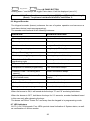
7. NEW ADDRESS AT SERIES 3000
7.1 Systems parameters address
System parameters 072
Modification: 072-5 Enable bypassed zones reporting at ARM - The parameter is
enabled by default.
System parameters 075
Enable Sounds in HOME mode - 075 - 1
New connection order enabled - 075 - 2
Enable Double report to Central station - 075 - 3
Enable Slow Response (for "Fast zones") - 075 - 4
Enable – Open/Close report by SMS 075 – 5
Enable Listen-in using ALR1 via DTMF - 075 - 6
Enable ON/OFF strobe via ON output - 075 - 7
Enable ALR1 Latching- 075 - 8
EasyLoad: Series 3000
remote modem is not
enabled by factory default
(security reason).
Check address "Enable PC
connection/Download via
modem" 076 - 1.
System parameters 076
Enable PC connection/Download via modem" - 076 - 1
Enable DISARM via DTMF remote command " - 076 - 2
Enable zones bypass by remote DTMF/PC " - 076 - 3
Enable date/time setting by remote PC " - 076 - 4
Enable SMS reporting- 076 - 5 set by default
Parameters 6, 7 see at programming table
Enable PC connection/Download via modem" - 076 - 1 (default not enabled)
To access the panel via remote PC this parameter must be set. The panel will not accept
a connection from a remote PC when it is ARMED or there was an alarm.
When the panel is disarmed, a connection is always possible if the user entered the
Answer Now command ("6"+"1"). Using the PC connection one can only ARM the panel,
but not disarm it.
It is not possible to cancel the ARM command.
When arming, the user can bypass some zones or set the Home mode. Zones
bypassing is possible only if enabled at 076 - 3.
Enable DISARM via DTMF remote command - 076 - 2 (default not enabled).The panel
can be accessed via telephone using DTMF commands when Armed or Disarmed (if
DTMF enabled at 074 - 6).
The user can disarm the panel using DTMF command only if the option is enabled at
076 - 2.
Enable zones bypass by remote DTMF/PC- 076 - 3 (default not enabled). Zones can be
bypassed by remote telephone or PC only if this option is enabled.
Disable date/time setting by remote PC - 076 - 4 (default not enabled - meaning that the
PC will SET the panel time and date t each connection). Setting this option will prevent
the remote PC to modify and set panel's date and time.
Enable SMS events reporting - 076 - 4 (default enabled).
28
The panel will report if this parameter is enabled and a valid SMSC telephone number
and one or two destination telephone numbers have been programmed.
7.2 Telephone and SMS address
Addresses modified:
Communicator Test Hour and minutes 004 def 00:01
Auto Arming Hour and minutes 006 def 00:00
Telephone numbers
There are 11 telephone numbers, 16 digits each.
No limitation on the numbers of pauses in a telephone number. The programmable digits
are: 0,1,2,3,4,5,6,7,8,9,*,#.
Telephone numbers addresses:
008 SMS Service Center – To this number the panel send the SMS data. In each
country the number is different call your PSTN telephone line to find the number.
009 SMS Destination number #1 (used to report events)
010 SMS Destination number #2 (used to report events)
011 SMS Destination number #3 (used to report events)
012 SMS Destination number #4 (used to report events)
(The Destination numbers are not dialed by the panel - they are included in the SMS)
013 Regular Telephone number plus follow me option #1
014 Regular Telephone number 2
015 Regular Telephone number 3
016 Regular Telephone number 4
017 Central Station number 1
018 Central Station number 2
Short Message Service via land telephone line (PSTN)
The panel sends Short Messages (SMS) via the land telephone line. The SMS service
must be enabled on the outgoing telephone line connected to the panel. To enable the
SMS reporting for the panel the installer must program:
- The SMS Service Center (SMSC) telephone number for Outgoing Messages (in some
countries there are two telephone numbers, one for Outgoing messages and one for
Incoming messages; in Israel for example the Outgoing telephone number is 14974800
and it is programmed automatically when returning to factory defaults). If required add
the "external line access" code.
- One or two Destination telephone numbers. Those numbers will receive the messages
sent by the panel. Each number must be programmed "as is" (without "access code") those numbers are not dialed by the panel - they are part of the SMS message.
- Enable the SMS reporting the installer will program 076 - 5 (set as a factory default).
7.3 Events reported by the SMS module
To set SMS language (English or Hebrew) see "200" commands.
29
SMS Test reporting
--------------------------------------------------Zone event Burglary Zone number and description (zone alarm restore not included)
24 hour zone number and description
Entry/exit Zone number and description
Fire Zone number and description
Panic Zone number and description
Tamper Zone number and description
--------------------------------------------------Disarm (Open) - by User number
- Via DTMF User number
- Duress (ambush) User number
- Via PC remote
- By Key
--------------------------------------------------Arm (Close) - by User number
- Via DTMF User number
- Auto arming by timer
- Via PC remote
- By Key
--------------------------------------------------AC Power - Failure
- Restore
--------------------------------------------------Battery - Low Battery
- Low Battery Restore
--------------------------------------------------Emergency - Panic
- Medical
- Fire
--------------------------------------------------PC remote Access
--------------------------------------------------Communication to Central Station Failure
Each event is time/date stamped.
To test the SMS reporting: Press/hold "6"+"5"
More features
* Reporting PC remote access to the CENTRAL station
If the panel was accessed by a remote PC (via the telephone line) then reports will be
sent to the Central station (using CID format only):
- Successful access/download: code 412, user 99
- Arm /Disarm by remote: code 407, user 99.
* PC connection is always recorded in the History log
* If the PC uploaded programming data to the panel then the history log will show the
following events:
xx PC Download Program table
xx PC Download
Telephone numbers
xx PC Download
User Codes
xx PC Download
Zones texts
30
* When the entry delay starts (by opening a delayed zone), the panel begins to dial to
the regular telephone numbers. In this case, the panel sends a siren sound via the
telephone. If an alarm condition starts (the panel was not disarmed), the panel will start
the normal reporting cycle:
Report to the Central Station, SMS reports and, finally, alarm reports using siren sound
and SVM recorded messages to the regular telephone numbers.
* Central Station test by "6"+"8"
If no telephone/ CS installed, dial test and CS test will give a function error.
* Activation of ON/OFF strobe via the ON output. Programmed at 075-7.
Arming: 2s ON, 1s OFF, 2s ON, 1s OFF, 2s ON, OFF
Disarming: 3s ON, 2s OFF, 3s ON, OFF
* Keypad warning from zones or troubles are "silenced" for 15 seconds after an enter or
a password.
* Alarms only history display - called by "0" + "4"
* Listen-in function in DTMF mode, using A1 output:
5 + 1 Start
5 + 0 Stop
* A1 output "Latching" - A1 can be set for an unlimited time. To set the feature program
"Enable A1 Latching" at 075-8
* A1 can be set (ON) by DTMF command 3+1 and reset (OFF) by DTMF command 4+1
If A1 was set - Latched by the DTMF command then it can be reset by "9" in disarmed
mode, DTMF command 4+1. Normal System Reset (as when arming / disarming) will not
release it.
- Each zone can be programmed to trigger Siren/SVM1/SVM2 alerts to four telephone
numbers.
- Siren, SVM1 and SVM2 telephone alert times can be programmed.
- The panel can report to both Central Stations (double report) and only once to the
Central Station that is available (one of the Central Station is in this case used as
backup in case of failure to contact the other one).
Program Double report to CS at 075 - 3
- Central Stations can be programmed to report in different formats, each one using it
own Subscriber ID.
- The communicator to central station has priority over SMS reporting and the dialing of
Siren/SVM alerts. The communication process will stop the alerts dialing. When it
completes, the alerts dialing is resumed from the first telephone number for a complete
number of repetitions.
Note that if the dialer is currently set to alert using siren and SVM1 and an input triggers
a SVM2 request, then the number of repetitions will be reset and the dialer will dial again
adding the new request to the alerts. This means that every time an input requests an
alert not yet active, the dialer will re-dial, so no subscriber will miss the event.
DTMF control: At the end of 1st Siren/SVM cycle, the user will be prompted to enter a
valid code; correct code enables access to the DTMF remote control functions.
31
7.4 Dialer reporting Programming locations
Zones to sound Siren via telephone 040 def 1234
Zones to activate SVM1 message 046---Zones to activate SVM1 message 047---Siren via telephone time seconds 053 def 10s
SVM1 via telephone time seconds 054 def 10s
SVM2 via telephone time seconds 055 def 10s
SVM1 is activated by the ON output of the board
SVM2 is activated by the A1 output of the board
There is no need for 072-7 "Enable Use of ON output as SVM trigger"
"ON" output is selected for SVM1 if there is at least one zone programmed at 046
"A1" output is selected for SVM2 if there is at least one zone programmed at 047
Other uses of ON and A1 are disabled if those outputs are selected for SVM1 and
SVM2.
Note: The alerts are output in cycles siren followed by SVM1 followed by SVM2. The
minimum call time is programmed at address 085. Program short time for each alert and
a reasonable "minimum call time". This way, whoever picks the telephone will have a
chance to listen to all alerts. For example:
Siren: 5 seconds
SVM1: 3 seconds (short message)
SVM2: 4 seconds
Total: 12 seconds
Minimum call time: 60 seconds. This means that the alerts will be present on the
telephone line for at least 60 seconds (equivalent to 5 repetitions) and if the "user" picks
the phone after 30 seconds he still has a chance to listen to the Siren, SVM1, SVM2.
Minimum call time - Seconds 085 def 60 (minimum 30s)
For pulse dialing:
"Make" time - 5 ms units 088 def 08
"Break" time - 5 ms units 089 def 12
Note: Make/Break time is in 5 ms units - unlike the units used in previous models of
AV-3004/48
Note: Subscriber ID codes must be programmed for each CS number, also for Contact
ID.
32
8. PROGRAMMING SHEET VERSION 1.09 LED
Factory Default Program marked with ( ); Blank Square means no default program
TELEPHONES & SMS Subscribers
TEST SIGNAL & AUTO ARMING TIME
SMS Center
No.
008
SMS Subsc’r
1
009
SMS Subsc’r
2
010
SMS Subsc’r
3
011
SMS Subsc’r
4
012
Telephone 1
Telephone 2
013
014
Telephone 3
Telephone 4
CS Tel 1
CS Tel 2
Not in use
015
016
017
018
019
Signal Test
Mode
003
00
Signal Test
Time
004
(00:01)
Reserved
Auto Arm
Time
006
00:00
Address 003 selects test mode: 00 – none, 01 - Only to CS, 02 - Only to SMS, 03 - CS and SMS
Tel. 1 is also ‘Follow Me’. Maximum 16 digits or # and *. At
Test signal (central station, SMS) 004, enter time in 24 hour
address 008 enter the provider SMS center number
format. Codes are defined at Addresses: 052, 073, 237, 255
To insert * in the phone number; Program system to dial in DTMF, Hold-down keys # and * (as panic), ‘A’ will be displayed.
If central phone add Pause during dialing hold-down key ‘0’, add pause only at add 008, not at address 009, 010.
Zones 5-8 are applicable in 8 zone mode, default is 4 zones
ZONE FEATURES
Feature
Fire zones
Zone In Use
Entry/Exit Delay 1 (set at 060)
Entry/Exit Delay 2 (set at 061)
Entry / Exit Follower
24-Hours Zone
Day Zone
Green Zone (one shot alarm)
Swinger Shut-Down
Chime (set at 068)
NO-EOL Resistor (not @ 8 zone mode)
Enable Zone Tamper (not @ 8 zone mode)
Delayed Power-Up
Fast or Very Slow Response (set at 059)
Group Bypass I (key 0 than 1)
Group Bypass II (key 0 than 2) (auto arm)
Manual Bypass (key 0 & zone number)
Siren Out
Alarm 1 (A1) Out
Reserved
Reserved
Dial on Alarm
Keypad sounder on Alarm
N.O. (normally open) zone
Pulse count zone (only for instant zone)
Panic Zone
Activate SVM message 1 via ON output
Activate SVM message 2 via A1 output
Address
019
020
021
022
023
024
025
026
027
028
029
030
031
032
033
034
035
036
037
038
039
040
041
042
043
045
046
047
1
2
3
4
1
1
2
3
4
5
6
7
8
5
6
7
8
2
1
2
3
4
1
1
2
3
4
1
1
1
2
2
2
3
3
3
4
4
4
5
5
5
6
6
6
7
7
7
8
8
8
1
1
2
2
3
3
4
4
5
5
6
6
7
7
8
8
SVM1 is activated by the ON output; SVM2 is activated by the A1 output. For auto arming with group bypass use Group 2 only.
Keypad Panic Alarm
050
Tamper Alarm
Siren on Panic
1
Tamper zone as 24H zone
A1 output activate at Panic
2
A1 activated on Tamper
Zone 4 / 8 (3048) as aux. key
3
Tel. Line Test at Disarmed
Reserved
4
Reserved
Telephone Report
(5)
Tel. Line fail activates buzzer
Enable buzzer on Panic
6
Tel. Line fail activates siren
Reserved
7
Dialer Report AC Power Fail
Address 052, CS test day: 1 - Sun 2 – Mon, 3 – Tues, 4 – Wed., 5 – Thu. 6 – Fri., 7 – Sat., 8 - All week's days, 0 – Clear all
Key 1 – Hold down test siren
Key 2 – Hold down display bypassed zones
Key 3 – Hold down display troubled zone/s
Key 6 than 5 hold down – Test SMS
Key 6 than 7 hold down – Test dial by dialer
Key 6 than 8 hold down – Test dial to C. Station
051
1
2
3
4
5
6
7
Set clock – Hold down 0 than 1, enter 4 digits HH:MM
Set date - Hold down 0 than 6, enter 6 digits dd:mm:yy
Enter to program mode – Hold down 8, than 1 9 9 4 than
Exit program mode and user program mode Hold Down 9
33
TIME-OUTS
Siren
sound
before
SVM
Sec's
1
053
0
SVM 1
Message
Length
SVM 2
Message
Length
Sec's
Sec's
1
054
0
1
055
056 set for pulse count zone
A1 Time
Sec's
066
3
0
Reserve
d
067
0
0
0
Chime
Time
Beeps
068
0
3
Pulse
Open/Clos
frame time e Report
(Max 30)
CS
Sec's
0
056
8
00=No,
01=yes
057
0
0
AC fail
report
delay
Zone
Response
time
Entry
Delay 1
Entry
Delay 2
Exit
Delay
Siren
Time
ON Siren
Time
OFF
Siren
Time
Minutes
m. Sec
Sec's
Sec's x 4
Sec's x 4
Minutes
Sec's
Sec's
1
058
0
0
059
5
1
060
2
0
061
0
0
062
8
0
063
4
1
064
5
0
Abort
Delay
Sec's
069
0
4
Notes: Address 059 adjusts the response time of zones selected as ‘Fast Response’. If Slow Response selected at 075-4 than counts in minutes,
the value in address 059 is multiplied by 4 and units are seconds, 63 is the maximum.
SYSTEM FEATURES – Values marked with ( ) are the factory default programming
Feature
Enable-Siren/Bell Test upon Arming
Enable-Keypad 3 Beeps upon Disarming
Enable-Buzzer upon Entry Delay
Enable-Keypad Tactile Beep
Disable-Keypad 4 LEDs display during Armed
Enable-Battery Test upon Arming
Reserved
Enable-Keypad Panic
070
1
(2)
(3)
(4)
5
(6)
7
(8)
Feature
Enable-Erase F. Me number on Disarm
Enable-Instant Arming via Key 5
Enable-Buzzer during exit delay
Enable-Display Alarmed Zone during alarm
Enable-Manual Bypass via Code No .1
Enable-Lock in Armed after Tamper Alarm
Enable-Momentary Key-Switch
Enable-Code ‘8’ as one time code
071
1
2
3
4
5
6
(7)
8
Feature
Enable-Bell mode
Enable-Detailed alarm history
Reserved
Activate ON output for ADSL filter line-cut
Enable-Report bypassed zones at Arming
Enable-Exit delay when delayed zones clear
Enable -’ON’ output as SVM trigger *
Enable-codes reset to default by * & #
072
(1)
(2)
(3)
4
(5)
6
7
(8)
Feature
Enable-Display troubled zones at Disarmed
Enable-Test to central station each hour
Enable-Self contain Bell (0V at alarm) **
Reserved
Enable- Group Bypass when Arm with Key
Enable - 2 Siren Beeps at Key Disarming
Enable - A1 output time follows Siren time
Enable - Outputs (A1, ON) 0V at active
073
(1)
2
3
4
5
6
(7)
8
Feature
Reserved
Enable-Activate A1 via DTMF
Enable-Auto reset zone after alarm timeout
Reserved
Reserved
Enable – DTMF control via telephone
Enable – Bypass Answer Machine
Enable - Echo Cancellation Tone (AUSTEL)
074
1
2
3
4
5
(6)
7
8
Feature
Enable – K. Pad & Sir sounds @ Home mod
Enable – AV-3048 New Zones Wiring way
Enable – Double report to central station
Enable – Slow response for address 032
Enable – Strobe signal on/off via ON output
Enable - A1 output at Latching mode
075
1
2
3
4
5
6
7
8
Feature
Enable – PC Up and download via modem
Enable – Disarming via remote DTMF
Enable – Zone/s bypass via remote DTMF
Enable – Date/Time setting by remote PC
Enable – SMS reporting
Enable – Send the LOGO text as SMS header
Enable – Instant dial by Delay zone/s
Reserved
076
1
2
3
(4)
(5)
6
7
8
Not in use
077
Enable – Open/Close report by SMS
Enable – Listen In activated by A1 output
34
065
4
Enable PC connection/Download via modem" - 076 - 1 (default not enabled). To access the panel via remote PC set 076-1. The
panel will not accept a connection from a remote PC when it is ARMED or there was an alarm. When the panel is disarmed, a
connection is always possible if the user entered the Answer Now command (hold down"6"+"1"). Using the PC connection one can
only ARM the panel, but not disarm it.
When Arming, user can bypass some zones or set the Home Mode (group bypass). Zones bypassing is possible only if enabled at
076 - 3.
Enable Disarm via DTMF remote command- 076 - 2 (default not enabled).The panel can be accessed via telephone using DTMF
commands when ARMED or DISARMED (if DTMF ENABLED at 074 - 6). The user can Disarm the panel using DTMF command only
if option 076 – 2 is enabled.
Enable zones bypass by remote DTMF/PC- 076 - 3 (default NOT ENABLED). Zones can be bypassed by remote telephone or PC
only if this option is enabled.
Enable date/time setting by remote PC - 076 - 4 (default ENABLED - meaning that the PC will SET the panel time and date at each
connection). Setting this option will prevent the remote PC to modify and set panel's date and time.
Send logo text as SMS header – New for revision 1.02, logo text is sent as header for SMS (sent from Av-Gad, for example). See
076-6
DIAL PARAMETERS
Pre-Dial
Delay
Sec's
0
080
0
Tel.
Line
Test
Intervals
Wait for Anti-Jam Dial tone Dial Mode
Dial
Delay detection
Tone
Sec's
0
081
4
Min.
Ring
Length
Sec's
1
082
0
Rings
Time
Out
Minutes 10 mS Seconds
(Max 99) (Max 20) (4 to 25)
094
095
096
0 0 1
2
0
5
Tel.
MSG
Time
InterCall
Delay
Re-Dial
Cycles
(max.)
Pulse
MAKE
00=No 0=Pulses Sec's
01=Yes 1=DTMF
083
084
085
0 0
0 1 5 0
Sec's
XX Cycle
5 mS
2
086
0
0
087
3
0
088
Pulse Inter Digit Rings
BREAK Delay
qut'y for
modem
8
5 mS
1
089
2
50 mS
2
090
0
Tel. Rings
1
091
0
Instant
modem
answer
Ring
Cycle
Width
00=No
01=Yes
092
0
1
100 mS
(1-25)
093
2
0
SMS send
trial
Units
(1-5)
097
0
2
Dial tone detection address 083 is at 00 by default.
Note address 091: The download is ENABLED by default. Setting 21 at address 091 disable modem (because 21 ring for modem not accepted by telephone net).
To ENABLE enter 01 to 20 at address 091 and 076-1. For Instant Modem Answer (Answer Now): Enter 01 in address 092, hold-down key 6 then hold-down key
1, ‘A’ displayed in confirmation. For special application, address 093 set the ring detector pulse width.
SET INSTALLER CODE: Address 099 provides setting of installer code (default 1994)
SET FACTORY DEFAULT: In address 200 enter 6 9, program will revert to factory default programming
35
COMMUNICATOR (dials to central station) PARAMETERS (by default set Contact ID)
TELE
PHONE
Receiver
CS Tel 1
TELE
PHONE
0
Format
201
Reserved
0
Format
202
Data
Format
Frequency
203
0
2
7
Receiver
CS Tel 2
Handshake
0
Handshake
Reserved
7
00 - Dialer only (No Communicator)
01 - Ademco, Silent Knight Slow,
Scantronic
02 - Radionics Fast
03 - Sescoa, Vertex, DCI, Franklin
04 - Silent Knight Fast
05 - Radionics, DCI, Franklin Slow
06 - Universal High Speed
07 - Contact ID or Ademco High Speed *
057 - Open/Close report to central station
0
Data
Format
Frequency
204
0
2
205
0
206
0
Protocol
0
Type
207
0
Protocol
0
Type
208
0
Sum
Check
(Parity)
209
0
0
Transmit
Inter MSG
Wait for
Rounds
211
0
0
Time
213
Handshake
215
2
0
Sum
Check
(Parity)
210
0
0
Transmit
Inter MSG
Wait for
Rounds
212
0
0
Time
214
Handshake
216
2
0
3
3
0
0
00=3 X 1
00=1400 Hz
00=Standard
00=None
00=2 Rnd
00=0.1 Sec
XX=Sec's
01=2300 Hz
01=4 X 1
01=Extend
01=S. Check
01=1 Rnd
30=3 Sec
02=Hi/Lo
Ademco H.S.
SurGurd Rec.
set 00 or 01
02=4 X 2
3 Sec's is
Default
03=3 X 2
00 disabled 01 enabled
00 - ‘No Communicator,’ is identical to ‘Dialer’ that generates sound upon alarm. ‘Rnd’ is shortening for ROUNDS. ‘S. Check’ is
shorting for ‘Sum Check’. ‘Hz’ is shorting for ‘Hertz’ (frequency unit). When Contact ID selected program only Group 1 Subscriber
ID at address 360 and 364.
Contact ID Format (known also as Ademco Express): This is the fastest to program and easiest to use format, with
communication speed achieved by the DTMF signaling.
When using this format, program only the CS telephone numbers and subscriber ID; all reports automatically transmitted, without
programming anything else.
To select the Contact ID format: In address 201 enter 07, same for address 202 is you need the back up reporting, enter the
subscriber ID (refer to part 10 of programming table). Also enter the subscriber ID at address 360 and 364, must be 4 digits
number.
In case the reporting fail try to change address 203 = 00, 204 = 00.
REPORT SELECTION
For communicator codes A to F, enter the following: A=10, B=11, C=12, D=13, E=14, F=15. Note: entering 0 0, is same as a blank.
Group 1
2
2
Report on Alarm
105
3
4
3
4
1
1
2
2
Zone Restore
107
3
4
3
4
1
1
Report Bypassed Zones
109
2
3
4
2
3
4
1
1
Group 2
ZONE
VALUE
ZONE
VALUE
Report on Alarm
106
PA
3
AC
1
LB
2
AC
1
Control Panel Restore
108
LB PA
2
3
ZONE
VALUE
36
ALARM, RESTORE, BYPASS ZONES, OPENING / CLOSING, SIGNAL TEST & FORCE OPENING CODES
Group 1
1
Alarm Codes - Single Codes
2
3
4
110 112 114 116
3
3
3
3
Z O N E S
(Alarm Code for Fire = 1)
CODES
111 113 115 117
1
2
3
4
Alarm Codes - Extended or 2 Digits
1
Group 2
Restore Codes - Single Codes
2
3
4
142 144 146 148
E
E
E
E
143 145 147 149
1
2
3
4
Restore Codes - Extended or 2 Digits
Bypassed Zones Codes - Single Codes
1
2
3
4
174 176 178 180
8
8
8
8
AC
Alarm Codes - Single Codes
LB PA
126 128 130
F
F
2
CODES
127 129 131
9
8
1
Alarm Codes - Extended or 2 Digits
Z O N E S
AC
CODES
158 160 162
E
E
E
Restore Codes - Single Codes
LB PA
159 161 163
9
B
A
Restore Codes - Extended or 2 Digits
CODES
Reserved
Z O N E S
CODES
175 177 179 181
1
2
3
4
Bypassed Zones - Extended or 2 Digits
220 222 224 226
C
C
C
C
Opening (Disarming) Codes-Single Digit
Single Digit
2
3
4
Test
Force
Opening
236
238 240 242 244
254
256
A CODE
B
B
B
B
D
221 223 225 227
1
2
3
4
Closing Codes - Extended or 2 Digits
237
239 241 243 245
9 CODE 1
2
3
4
Opening Codes - Extended or 2 Digits
1
Closing (Arming) Codes-Single Digit
2
3
4
CODES
Test USER
1
255
9
257
In order to disable reporting Closing/Opening change program at address 072; remove value ’3’.
When SIGNAL TEST is enabled, you can specify to report System Status (as default for Extended or 2 digits) by programming for example ‘A’
(Armed) at 236, and ‘D’ (Disarmed) at 254, ‘9’ is the test signal code. For System Status report, select extended or two digits format.
For programming the End-User codes 1 to 8 (Arm/Disarm code) via installer programming mode, hold down 8 enter 1234,
# program new codes by first entering the code index (1, 2, 3..8), enter the new required code than #, exit with 99 than #
Entering the Disarming code in reverse order activates the Force Opening Code (Ambush) report to central station.
TEL. 2 - SUBSCRIBER ID NUMBER
Note: For subscriber ID that contains a ‘0’ (zero), enter 10 in place of 0. ‘0’ will be displayed as ‘A.’ Do not enter 0 0.
Group 1
Group 2
Alarm / Restore ID Alarm / Restore ID Open. / Closing ID
260 261 262 263 268 269 270 271 276 277 278 279
37
To easily program the subscriber ID number, as a sequence of 4 digits use the EASY Program.
Even if your code is 3 digits only you must enter 4 digits, the 4th digit can be any digit and the system will disregard the 4th digit.
EASY Program
EASY Program
EASY Program
Alarm / Restore ID
Alarm / Restore ID
Open. / Closing ID
360
368
376
TEL. 3 - SUBSCRIBER ID NUMBER
Group 1
Group 2
Alarm / Restore ID Alarm / Restore ID Open. / Closing ID
264 265 266 267 272 273 274 275 280 281 282 283
EASY Program
EASY Program
EASY Program
Alarm / Restore ID
Alarm / Restore ID
Open. / Closing ID
364
372
380
To easily program the subscriber ID number, as a sequence of 4 digits use the EASY Program.
Even if your code is 3 digits only you must enter 4 digits, the 4th digit can be any digit and the system will disregard the 4th digit.
Values beneath addresses are default programming.
9. Powering Up & Wiring Diagram
9.1 Before Powering Up
Place Control Panel in a well-ventilated location and as far as possible from any
heat, transmission and high humidity source.
Do not place high power RF wireless transmitters near Control Panel.
Check for proper grounding.
Make sure detectors, keypads or any other devices are connected to the Control
Panel in their correct polarities.
Connect a momentary voltage to the siren; making sure a ‘beep’ is sounded. In case
of no beep, check for a short circuit or improperly connected wires.
Power-up through transformer, if system seems to operate properly connect the
battery.
Better do not connect any sensors or other devices to the battery terminals.
Series 3000 is compatible with 12V smoke detectors, common collector type or relay
(-) output on alarm, however, adding a manual Reset switch is required.
Momentary switch achieves smoke detector reset. The switch (or relay) disconnects
power to smoke detector following a smoke alarm.
38
9.2 Technical Specifications AV-3044
Operating Temperature
Relative Humidity
Input AC Power
Dynamic Inner Memory
Auxiliary Power Output
Siren Outputs (1)
Dialer: Programmable 3 telephone numbers & 1
Follow-Me telephone number (4 tel. numbers).
Three tel. Interfaces are available: 600Ω, E, AS
Voice module input. Multi-format central-station
communicator. E version is TBR-21 approved, AS
version is AUSTEL approved.
Jumper for CCTV modem/GSM mode
SMS via PSTN lines
Remote Indications on Wire Terminal
EOL Zone Loop Resistor (Burglary)
EOL Zone Loop Resistor (Tamper)
Zone Loop Voltage
Zone Loop Current
RFI and EMI protection
Auxiliary Power (Max.)
Battery Charging Current (Max.)
Battery Test: Indication at keypad or remote
indication via communicator.
Standby Power Consumption at Disarmed mode,
and Keypad display is Off
Maximum Remote Station (Keypads)
Remote Station Current Consumption
Housing Dimensions
Housing
Gross Shipping Weight (without transformer)
Fuses: Electronic Resetable Fuses
-10C to 60C
80% maximum
16V AC step-down Transformer Rated
current: 1.2 Ampere
EEprom, store 250 events
13.6 Volts +/- 5%, Regulated
Short & Overload circuit protection
Siren or Bell Selectable
Bell Mode: 13.6V DC-0.65A
Fuse protected
Siren: 8 Ohms, 20W
Pulse Dialing programmable
parameters
DTMF: Touch Tone dialing
Max. Telephone number length:
16 digits and 4 pauses.
To four numbers
Open Collector type output
100 mA Max. @ 12V DC
2,200 Ohms, 0.25W, +/- 5%
4,700 Ohms, 0.25W, +/- 5%
5 to 6.5 V DC
3 mA with End-Of-Line Resistor
Zone line shorting, cutting, high voltage
lightning
protection,
Electro
Static
Discharge Traps, RF Filters. Telephone
line Lighting protection circuit
AV-3048/3044: 13.6 VDC 0.9A Combined
Aux. Power and Keypad outputs
550 mA, current limitation
Performed at 0.5A load for 1 second.
Low Battery indication below 10.5V
Tested upon Arming and every 60
minutes during Armed and Disarmed
90 mA, +/- 10 %
3 Keypads AV-701, AV-702, AV-702TP
30 mA
(H) 30, (D) 9, (W) 23 cm
ABS box, White color
Option: Metal, Anodized, lockable metal
box. Epoxy anti-static powder painted
1.2 kg. 6 PC's per master box
Auxiliary Power: 1.25A
Sirens: 2 X 1.25A (fuse for each siren)
Backup Battery Fuse: 2.5A
Av-Gad Systems Ltd. reserves the right to modify and upgrade products without prior notice.
39
9.3 Wiring Diagram
AV-3044 LED Wiring Diagram
Order cable (item
WSVM) to fit KEY plug
VA9
+
VA7 VA8
C43
+
RF2
R69
D15
R74
R76
R78
R77
R79
R62R64 R65R66 R67R68 R70R71
R87
C
B
E
Q18
1
2
3
4
VA1
SVM IN
B
E
C
B
E
B
B
E
R83
E
B
C
C42
R84
Q17
R56
U6
R81
R82
+
VA4
R58
D17
D16
Q20
Q14
R85
Add ADSL
Filter for line
With ADSL
AV-03
ADSL
Filter
TEL. LINE
PHONES
C44
K1
C
B
E
Q19
R86
-V
R55
+
C
B
E
R44
R53
R54
R80
U7
ON A1 YE OR
VA10
3000 SER. V3
Refer to Zone wiring details
AV-GAD
-V
8 Zone Mode Wiring
2K2
40
Display Zone
No. 5
ZONE
DISPLAY
4K7 Resistor
Colors Yellow,
Violet ,Red
4K7
Display
Zone No. 1
EASYLOADER AV-701
-V
PIR 2
2K2 Resistor
Colors Red ,Red,
Red
Zone4< 5 6 7 8 K7
Figure 1: Optional new 8 zones
wiring in AV-3044 LED
R49
R50
R75
U5
PIR 1
Zone2< 1 2 3 4 K2
C40
R48
R73
RF3
C39
R72
+12V -V
Cold Water
Grounding, run 3
meters max, use 16
AWG (3 mm) thick wire
++
C31
VA5
PHONES TEL-LINE
R63
R61
R43
C38
+12V & -V
AUSTEL
To 220V AC
R60 Q15 1
Q11
D12
JP5
JP4
E
B
FA3
T1
Don’t change
Q16
KEY
U4
R31
U3
C34
SVM IN
(voice module)
R30
R59
C29
JP2
VA3
VCC
Y1
AC
Fr 16V
Y e om
l
Wi l o w
res
C18
R22
C11
+
SERIAL
(AV-232)
TX
R21
VA6
C33
R47
R20
+
D13
R16
R17
R18
Version
here
C28
C27
C25
R15
R14
++
B
E
Q8
B
E
++
R37
++
+ C22
D7
RX
-V
+V
C12
R19
+
Q13
E
E
R12 Q6
C9
R90
D10
B
SERIAL
R6
Q5
C10
R57
KEY
D5
Q4
B
R46
D4
R51
R34
R40C26
C24
R41
Q10
JP3
++Q9
D9
R35
R36
B
E
R11
C37
R33
-
R27 R26
C17
D11
C23
C14
C13
VDD C15
C35
AC 16V
To Yellow
wire
R24
R10
D2
R13
JP1
R5
E
C
Q3
R4
R28 C19
R25
C36
Fuse
C7
R23
C16
++
Sirens
Ground
To 220V AC
AV-GAD
Q7
++
+SIR
C4
R8
C8
D6
D1
C5
R32
R7
C6
O
I
-SIR
+B
RF1
+BATT
R9
Q2 B
R3
R2
FA2
VA2
Red to +
D3
C1
-B
VA11
-BATT
PC85D/5285
C3
++
E
Q1
C2
FA1
C30
12V SLA Battery
KEY
Auxiliary Power
Output
Regulated 13.8V.
Observe maximum
current-0.8A,
combined keypad and
Aux. power
+
-SIR +SIR AC 16VAC
To prevent electrical
shock, disengage the
System and
disconnect the
telephone line before
servicing this unit.
R29
WARNING:
OR
YE
Siren
1
Shunt
Display
2
Delay
Delete
4
Chime
5
7
Program
8
Shunt
0
Test
*
Status
Telephone
Reset
3
6
9
#
AV-Gad Keypad
In 8 zone mode must use EOL
Resistors are 2,220K or 4,700K Ohms
Cut when
CCTV modem
or GSM
connected