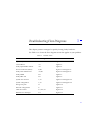
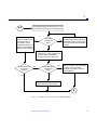
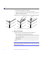
1
SPARCserver 1000 System Service Manual
Warning – Procedures contained in this manual must be performed by
qualified service-trained maintenance providers.
Refer to the section entitled “Notes, Cautions, and Warnings” found in the
Preface of the front matter of this service manual Binder.
A Sun Microsystems, Inc. Business
2550 Garcia Avenue
Mountain View, CA 94043 U.S.A.
415 960-1300 FAX 415 969-9131
Part No.: 801-2895-15
Revision A, June 1996
Copyright 1996 Sun Microsystems, Inc. 2550 Garcia Avenue, Mountain View, California 94043-1100 U.S.A.
All rights reserved. This product or document is protected by copyright and distributed under licenses restricting its use, copying, distribution,
and decompilation. No part of this product or document may be reproduced in any form by any means without prior written authorization of
Sun and its licensors, if any.
Portions of this product may be derived from the UNIX® system and from the Berkeley 4.3 BSD system, licensed from the University of
California. UNIX is a registered trademark in the United States and in other countries and is exclusively licensed by X/Open Company Ltd.
Third-party software, including font technology in this product, is protected by copyright and licensed from Sun’s suppliers.
RESTRICTED RIGHTS LEGEND: Use, duplication, or disclosure by the government is subject to restrictions as set forth in subparagraph (c)(1)(ii)
of the Rights in Technical Data and Computer Software clause at DFARS 252.227-7013 and FAR 52.227-19.
Sun, Sun Microsystems, the Sun logo, and Solaris are trademarks or registered trademarks of Sun Microsystems, Inc. in the United States and in
other countries. All SPARC trademarks are used under license and are trademarks or registered trademarks of SPARC International, Inc. in the
United States and in other countries. Products bearing SPARC trademarks are based upon an architecture developed by Sun Microsystems, Inc.
The OPEN LOOK® and Sun™ Graphical User Interfaces were developed by Sun Microsystems, Inc. for its users and licensees. Sun
acknowledges the pioneering efforts of Xerox Corporation in researching and developing the concept of visual or graphical user interfaces for the
computer industry. Sun holds a nonexclusive license from Xerox to the Xerox Graphical User Interface, which license also covers Sun’s licensees
who implement OPEN LOOK GUIs and otherwise comply with Sun’s written license agreements.
X Window System is a trademark of X Consortium, Inc.
THIS PUBLICATION IS PROVIDED “AS IS” WITHOUT WARRANTY OF ANY KIND, EITHER EXPRESS OR IMPLIED, INCLUDING,
BUT NOT LIMITED TO, THE IMPLIED WARRANTIES OF MERCHANTABILITY, FITNESS FOR A PARTICULAR PURPOSE, OR
NON-INFRINGEMENT.
Copyright 1996 Sun Microsystems, Inc., 2550 Garcia Avenue, Mountain View, Californie 94043-1100 U.S.A.
Tous droits réservés. Ce produit ou document est protégé par un copyright et distribué avec des licences qui en restreignent l’utilisation, la copie
et la décompilation. Aucune partie de ce produit ou de sa documentation associée ne peut être reproduite sous aucune forme, par quelque moyen
que ce soit, sans l’autorisation préalable et écrite de Sun et de ses bailleurs de licence, s’il y en a.
Des parties de ce produit pourront être derivées du système UNIX® et du système Berkeley 4.3 BSD licencié par l’Université de Californie. UNIX
est une marque enregistrée aux Etats-Unis et dans d’autres pays, et licenciée exclusivement par X/Open Company Ltd. Le logiciel détenu par des
tiers, et qui comprend la technologie relative aux polices de caractères, est protégé par un copyright et licencié par des fournisseurs de Sun.
Sun, Sun Microsystems, le logo Sun, et Solaris sont des marques déposées ou enregistrées de Sun Microsystems, Inc. aux Etats-Unis et dans
d’autres pays. Toutes les marques SPARC, utilisées sous licence, sont des marques déposées ou enregistrées de SPARC International, Inc. aux
Etats-Unis et dans d’autres pays. Les produits portant les marques SPARC sont basés sur une architecture développée par Sun Microsystems, Inc.
Les utilisateurs d’interfaces graphiques OPEN LOOK® et Sun™ ont été développés de Sun Microsystems, Inc. pour ses utilisateurs et licenciés.
Sun reconnaît les efforts de pionniers de Xerox Corporation pour la recherche et le développement du concept des interfaces d’utilisation visuelle
ou graphique pour l’industrie de l’informatique. Sun détient une licence non exclusive de Xerox sur l’interface d’utilisation graphique, cette
licence couvrant aussi les licenciés de Sun qui mettent en place les utilisateurs d’interfaces graphiques OPEN LOOK et qui en outre se
conforment aux licences écrites de Sun.
Le système X Window est un produit du X Consortium, Inc.
CETTE PUBLICATION EST FOURNIE "EN L’ETAT" SANS GARANTIE D’AUCUNE SORTE, NI EXPRESSE NI IMPLICITE, Y COMPRIS, ET
SANS QUE CETTE LISTE NE SOIT LIMITATIVE, DES GARANTIES CONCERNANT LA VALEUR MARCHANDE, L’APTITUDE DES
PRODUITS A REPONDRE A UNE UTILISATION PARTICULIERE OU LE FAIT QU’ILS NE SOIENT PAS CONTREFAISANTS DE PRODUITS
DE TIERS.
Please
Recycle
Revision History
Revision
Dash
Date
Comments
801-2895-15
-A
June 1996
4th Revision to FCS
801-2895-13
-A
October 1994
3rd Revision to FCS
801-2895-12
-A
May 1994
2nd Revision to FCS
801-2895-11
-A
August 1993
1st Revision to FCS
801-2895-10
-A
May 1993
First Customer Ship (FCS)
SPARCserver 1000 System Service Manual—June 1996
Contents
Preface . . . . . . . . . . . . . . . . . . . . . . . . . . . . . . . . . . . . . . . . . . . . . . .
xxi
Part 1 —System Information
1. Product Description . . . . . . . . . . . . . . . . . . . . . . . . . . . . . . . . . . .
1-1
1.1 System Features . . . . . . . . . . . . . . . . . . . . . . . . . . . . . . . . . .
1-1
1.1.1 Chassis Assembly . . . . . . . . . . . . . . . . . . . . . . . . . . . .
1-4
1.1.2 Power Supply . . . . . . . . . . . . . . . . . . . . . . . . . . . . . . .
1-5
1.1.3 Fan Tray . . . . . . . . . . . . . . . . . . . . . . . . . . . . . . . . . . . .
1-6
1.1.4 SCSI Tray Assembly . . . . . . . . . . . . . . . . . . . . . . . . . .
1-7
1.1.5 System Board . . . . . . . . . . . . . . . . . . . . . . . . . . . . . . . .
1-8
1.1.6 Options . . . . . . . . . . . . . . . . . . . . . . . . . . . . . . . . . . . . .
1-9
1.1.7 External Options . . . . . . . . . . . . . . . . . . . . . . . . . . . . .
1-9
1.1.8 Internal Options . . . . . . . . . . . . . . . . . . . . . . . . . . . . . 1-10
Part 2 —Troubleshooting
2. Troubleshooting Overview . . . . . . . . . . . . . . . . . . . . . . . . . . . . .
2-1
2.1 System Control . . . . . . . . . . . . . . . . . . . . . . . . . . . . . . . . . . .
2-1
v
2.2 Status Lights and Indicators . . . . . . . . . . . . . . . . . . . . . . . .
2-3
3. Diagnostics and Commands for Troubleshooting. . . . . . . . . .
3-1
3.1 Diagnosing Problems . . . . . . . . . . . . . . . . . . . . . . . . . . . . . .
3-1
3.1.1 LEDs . . . . . . . . . . . . . . . . . . . . . . . . . . . . . . . . . . . . . . .
3-1
3.1.2 Console Messages . . . . . . . . . . . . . . . . . . . . . . . . . . . .
3-2
3.2 Using prtdiag . . . . . . . . . . . . . . . . . . . . . . . . . . . . . . . . . . .
3-3
3.3 Using probe scsi . . . . . . . . . . . . . . . . . . . . . . . . . . . . . . .
3-4
3.4 Precautions when Using POST . . . . . . . . . . . . . . . . . . . . . .
3-6
3.5 Precautions when Using OBP . . . . . . . . . . . . . . . . . . . . . . .
3-6
3.5.1 System Boards with PROM Revision 2.11 (or Lower) 3-6
3.5.2 System Boards with PROM Revision 2.13 (or Higher) 3-7
3.6 Connecting a Terminal to the System Master . . . . . . . . . .
3-8
3.7 Running OBP and POST . . . . . . . . . . . . . . . . . . . . . . . . . . . 3-10
3.8 Interpreting System Board LEDs . . . . . . . . . . . . . . . . . . . . 3-17
3.8.1 While POST Is Running . . . . . . . . . . . . . . . . . . . . . . . 3-17
3.8.2 After POST Ends . . . . . . . . . . . . . . . . . . . . . . . . . . . . . 3-17
3.9 Disabling and Enabling the Link Integrity Test . . . . . . . . 3-18
3.10 SuperSPARC Modules . . . . . . . . . . . . . . . . . . . . . . . . . . . . . 3-18
3.11 SIMMs and NVSIMMs . . . . . . . . . . . . . . . . . . . . . . . . . . . . . 3-18
4. Troubleshooting Flow Diagrams . . . . . . . . . . . . . . . . . . . . . . . .
4-1
4.1 Flow Diagrams . . . . . . . . . . . . . . . . . . . . . . . . . . . . . . . . . . .
4-2
Part 3 —Preparing for Service
vi
5. Safety and Tools Requirements . . . . . . . . . . . . . . . . . . . . . . . . .
5-1
5.1 Safety Precautions . . . . . . . . . . . . . . . . . . . . . . . . . . . . . . . .
5-1
SPARCserver 1000 System Service Manual—June 1996
5.2 Tools Required . . . . . . . . . . . . . . . . . . . . . . . . . . . . . . . . . . .
5-2
6. Powering Off and On . . . . . . . . . . . . . . . . . . . . . . . . . . . . . . . . . .
6-1
6.1 Powering Off the System . . . . . . . . . . . . . . . . . . . . . . . . . . .
6-1
6.2 Restarting the System. . . . . . . . . . . . . . . . . . . . . . . . . . . . . .
6-3
6.3 Boot Messages. . . . . . . . . . . . . . . . . . . . . . . . . . . . . . . . . . . .
6-8
Part 4 —Subassembly Removal and Replacement
7. Internal Access . . . . . . . . . . . . . . . . . . . . . . . . . . . . . . . . . . . . . . .
7-1
7.1 Front Panel . . . . . . . . . . . . . . . . . . . . . . . . . . . . . . . . . . . . . .
7-1
7.2 EMI Shield . . . . . . . . . . . . . . . . . . . . . . . . . . . . . . . . . . . . . . .
7-2
7.3 Air Restrictor Boards . . . . . . . . . . . . . . . . . . . . . . . . . . . . . .
7-3
7.4 Side Panels. . . . . . . . . . . . . . . . . . . . . . . . . . . . . . . . . . . . . . .
7-4
7.5 Top Panel . . . . . . . . . . . . . . . . . . . . . . . . . . . . . . . . . . . . . . . .
7-5
7.6 Bottom Panel . . . . . . . . . . . . . . . . . . . . . . . . . . . . . . . . . . . . .
7-8
8. Major Subassemblies . . . . . . . . . . . . . . . . . . . . . . . . . . . . . . . . . .
8-1
8.1 Fan Tray . . . . . . . . . . . . . . . . . . . . . . . . . . . . . . . . . . . . . . . . .
8-2
8.1.1 Removal . . . . . . . . . . . . . . . . . . . . . . . . . . . . . . . . . . . .
8-2
8.1.2 Replacement . . . . . . . . . . . . . . . . . . . . . . . . . . . . . . . .
8-3
8.2 SCSI Tray Assembly . . . . . . . . . . . . . . . . . . . . . . . . . . . . . . .
8-3
8.2.1 Removal . . . . . . . . . . . . . . . . . . . . . . . . . . . . . . . . . . . .
8-3
8.2.2 Replacement . . . . . . . . . . . . . . . . . . . . . . . . . . . . . . . .
8-5
8.3 Power Supply . . . . . . . . . . . . . . . . . . . . . . . . . . . . . . . . . . . .
8-5
8.3.1 Removal . . . . . . . . . . . . . . . . . . . . . . . . . . . . . . . . . . . .
8-5
8.3.2 Replacement . . . . . . . . . . . . . . . . . . . . . . . . . . . . . . . .
8-6
8.4 Backplane . . . . . . . . . . . . . . . . . . . . . . . . . . . . . . . . . . . . . . .
8-7
Contents
vii
8.4.1 Removal . . . . . . . . . . . . . . . . . . . . . . . . . . . . . . . . . . . .
8-7
8.4.2 Replacement . . . . . . . . . . . . . . . . . . . . . . . . . . . . . . . .
8-9
9. Storage Devices . . . . . . . . . . . . . . . . . . . . . . . . . . . . . . . . . . . . . . .
9-1
9.1 CD-ROM Drive: SunCD Plus and SunCD 2Plus . . . . . . .
9-2
9.1.1 Removal . . . . . . . . . . . . . . . . . . . . . . . . . . . . . . . . . . . .
9-2
9.1.2 Replacement . . . . . . . . . . . . . . . . . . . . . . . . . . . . . . . .
9-3
9.2 Tape Drive . . . . . . . . . . . . . . . . . . . . . . . . . . . . . . . . . . . . . . .
9-4
9.2.1 Removal . . . . . . . . . . . . . . . . . . . . . . . . . . . . . . . . . . . .
9-4
9.2.2 Replacement . . . . . . . . . . . . . . . . . . . . . . . . . . . . . . . .
9-5
9.3 Disk Drive . . . . . . . . . . . . . . . . . . . . . . . . . . . . . . . . . . . . . . .
9-5
9.3.1 Removal . . . . . . . . . . . . . . . . . . . . . . . . . . . . . . . . . . . .
9-5
9.3.2 Replacement . . . . . . . . . . . . . . . . . . . . . . . . . . . . . . . .
9-7
9.4 Control Board . . . . . . . . . . . . . . . . . . . . . . . . . . . . . . . . . . . .
9-7
9.4.1 Removal . . . . . . . . . . . . . . . . . . . . . . . . . . . . . . . . . . . .
9-8
9.4.2 Replacement . . . . . . . . . . . . . . . . . . . . . . . . . . . . . . . .
9-8
9.5 Disk Card (Option) . . . . . . . . . . . . . . . . . . . . . . . . . . . . . . . .
9-9
9.5.1 Removal . . . . . . . . . . . . . . . . . . . . . . . . . . . . . . . . . . . .
9-9
9.5.2 Replacement . . . . . . . . . . . . . . . . . . . . . . . . . . . . . . . . 9-11
9.6 Disk Card Disk Drive . . . . . . . . . . . . . . . . . . . . . . . . . . . . . . 9-14
Part 5 —System Board
10. System Board Overview . . . . . . . . . . . . . . . . . . . . . . . . . . . . . . . 10-1
10.1 Damage Prevention . . . . . . . . . . . . . . . . . . . . . . . . . . . . . . . 10-1
10.2 Handling System Boards and Subassemblies . . . . . . . . . . 10-1
10.3 System Board Description . . . . . . . . . . . . . . . . . . . . . . . . . . 10-2
viii
SPARCserver 1000 System Service Manual—June 1996
10.4 System Board Block Diagram . . . . . . . . . . . . . . . . . . . . . . . 10-4
11. System Board and Component Replacement . . . . . . . . . . . . . . 11-1
11.1 System Board. . . . . . . . . . . . . . . . . . . . . . . . . . . . . . . . . . . . . 11-1
11.1.1 Removal . . . . . . . . . . . . . . . . . . . . . . . . . . . . . . . . . . . . 11-1
11.1.2 Replacement . . . . . . . . . . . . . . . . . . . . . . . . . . . . . . . . 11-4
11.2 Using Standoffs. . . . . . . . . . . . . . . . . . . . . . . . . . . . . . . . . . . 11-5
11.3 SuperSPARC Modules . . . . . . . . . . . . . . . . . . . . . . . . . . . . . 11-6
11.3.1 Removing a SuperSPARC Module . . . . . . . . . . . . . . 11-7
▼ SuperSPARC Module A . . . . . . . . . . . . . . . . . . . . . . . 11-8
▼ SuperSPARC Module B . . . . . . . . . . . . . . . . . . . . . . . 11-8
11.3.2 Replacing a SuperSPARC Module . . . . . . . . . . . . . . 11-9
11.4 SBus Cards. . . . . . . . . . . . . . . . . . . . . . . . . . . . . . . . . . . . . . . 11-10
11.4.1 Removal . . . . . . . . . . . . . . . . . . . . . . . . . . . . . . . . . . . . 11-11
11.4.2 Preparing a New SBus Card . . . . . . . . . . . . . . . . . . . 11-12
11.4.3 Installing an SBus Card . . . . . . . . . . . . . . . . . . . . . . . 11-15
11.5 SIMMs and NVSIMMs . . . . . . . . . . . . . . . . . . . . . . . . . . . . . 11-16
11.5.1 Removal . . . . . . . . . . . . . . . . . . . . . . . . . . . . . . . . . . . . 11-17
11.5.2 Replacement . . . . . . . . . . . . . . . . . . . . . . . . . . . . . . . . 11-19
11.5.3 NVSIMM . . . . . . . . . . . . . . . . . . . . . . . . . . . . . . . . . . . 11-20
11.6 OpenBoot PROMs . . . . . . . . . . . . . . . . . . . . . . . . . . . . . . . . 11-20
11.6.1 Removal . . . . . . . . . . . . . . . . . . . . . . . . . . . . . . . . . . . . 11-20
11.6.2 Replacement . . . . . . . . . . . . . . . . . . . . . . . . . . . . . . . . 11-21
11.7 System Restart. . . . . . . . . . . . . . . . . . . . . . . . . . . . . . . . . . . . 11-22
Part 6 —Illustrated Parts Breakdown
Contents
ix
12. Illustrated Parts Breakdown . . . . . . . . . . . . . . . . . . . . . . . . . . . . 12-1
12.1 Replaceable Units . . . . . . . . . . . . . . . . . . . . . . . . . . . . . . . . . 12-1
12.2 Exterior Components . . . . . . . . . . . . . . . . . . . . . . . . . . . . . . 12-4
12.3 Chassis Assembly . . . . . . . . . . . . . . . . . . . . . . . . . . . . . . . . . 12-5
12.4 SCSI Tray Assembly . . . . . . . . . . . . . . . . . . . . . . . . . . . . . . . 12-6
Part 7 —Appendixes, Glossary, Index
A. Product Specifications . . . . . . . . . . . . . . . . . . . . . . . . . . . . . . . . . A-1
A.1 Physical Specifications . . . . . . . . . . . . . . . . . . . . . . . . . . . . . A-1
A.2 Electrical Specifications . . . . . . . . . . . . . . . . . . . . . . . . . . . . A-2
A.3 Environmental Requirements . . . . . . . . . . . . . . . . . . . . . . . A-2
x
B. Functional Description . . . . . . . . . . . . . . . . . . . . . . . . . . . . . . . .
B-1
B.1 System Overview . . . . . . . . . . . . . . . . . . . . . . . . . . . . . . . . .
B-1
B.1.1 System Board . . . . . . . . . . . . . . . . . . . . . . . . . . . . . . . .
B-1
B.2 System Architecture . . . . . . . . . . . . . . . . . . . . . . . . . . . . . . .
B-2
B.3 Arbitration System . . . . . . . . . . . . . . . . . . . . . . . . . . . . . . . .
B-3
B.4 SuperSPARC Module . . . . . . . . . . . . . . . . . . . . . . . . . . . . . .
B-4
B.5 I/O Unit . . . . . . . . . . . . . . . . . . . . . . . . . . . . . . . . . . . . . . . . .
B-4
B.6 Main Memory Unit. . . . . . . . . . . . . . . . . . . . . . . . . . . . . . . .
B-5
B.7 Control Board . . . . . . . . . . . . . . . . . . . . . . . . . . . . . . . . . . . .
B-5
B.8 SBus Cards. . . . . . . . . . . . . . . . . . . . . . . . . . . . . . . . . . . . . . .
B-6
B.9 Power Distribution . . . . . . . . . . . . . . . . . . . . . . . . . . . . . . . .
B-6
B.9.1 Power Supply . . . . . . . . . . . . . . . . . . . . . . . . . . . . . . .
B-6
C. SIMMs and Jumpers. . . . . . . . . . . . . . . . . . . . . . . . . . . . . . . . . . .
C-1
C.1 SIMM Configuration . . . . . . . . . . . . . . . . . . . . . . . . . . . . . .
C-1
SPARCserver 1000 System Service Manual—June 1996
C.1.1 System Board Rules . . . . . . . . . . . . . . . . . . . . . . . . . .
C-1
C.1.2 Locating a Failing SIMM . . . . . . . . . . . . . . . . . . . . . .
C-3
C.2 Jumper Configuration . . . . . . . . . . . . . . . . . . . . . . . . . . . . .
C-3
D. Connector Pinouts. . . . . . . . . . . . . . . . . . . . . . . . . . . . . . . . . . . . . D-1
D.1 Connector Locations. . . . . . . . . . . . . . . . . . . . . . . . . . . . . . .
D-1
D.2 Keyboard and Mouse Connector . . . . . . . . . . . . . . . . . . . .
D-2
D.3 Serial Port Connectors . . . . . . . . . . . . . . . . . . . . . . . . . . . . .
D-3
D.4 SBus Connectors . . . . . . . . . . . . . . . . . . . . . . . . . . . . . . . . . .
D-4
D.5 Backplane Connector . . . . . . . . . . . . . . . . . . . . . . . . . . . . . .
D-7
D.6 SuperSPARC Module Connectors . . . . . . . . . . . . . . . . . . .
D-9
E. General Rules for System Configuration . . . . . . . . . . . . . . . . .
E-1
E.1 Selecting Installation Locations . . . . . . . . . . . . . . . . . . . . .
E-1
E.2 System Master Board . . . . . . . . . . . . . . . . . . . . . . . . . . . . . .
E-1
E.2.1 Identifying the System Master. . . . . . . . . . . . . . . . . .
E-2
E.2.2 Minimum Requirements for the System Master . . .
E-2
E.2.3 Selecting the System Master Board . . . . . . . . . . . . . .
E-3
E.3 System Slave Boards. . . . . . . . . . . . . . . . . . . . . . . . . . . . . . .
E-5
E.3.1 SuperSPARC Modules . . . . . . . . . . . . . . . . . . . . . . . .
E-5
E.3.2 SBus Cards . . . . . . . . . . . . . . . . . . . . . . . . . . . . . . . . . .
E-7
E.3.3 SIMMs. . . . . . . . . . . . . . . . . . . . . . . . . . . . . . . . . . . . . .
E-8
E.4 Selecting Drive ID Numbers in the SCSI Tray . . . . . . . . . E-11
E.5 Connecting Cables . . . . . . . . . . . . . . . . . . . . . . . . . . . . . . . . E-16
E.5.1 SCSI Cables . . . . . . . . . . . . . . . . . . . . . . . . . . . . . . . . . E-16
E.5.2 Ethernet Cables . . . . . . . . . . . . . . . . . . . . . . . . . . . . . . E-16
Contents
xi
E.5.3 Video Cables . . . . . . . . . . . . . . . . . . . . . . . . . . . . . . . . E-16
Glossary. . . . . . . . . . . . . . . . . . . . . . . . . . . . . . . . . . . . . . . . Glossary-1
xii
SPARCserver 1000 System Service Manual—June 1996
Figures
Figure 1-1
SPARCserver 1000 System . . . . . . . . . . . . . . . . . . . . . . . . . . . . . .
1-2
Figure 1-2
Internal Components . . . . . . . . . . . . . . . . . . . . . . . . . . . . . . . . . .
1-3
Figure 1-3
Chassis Assembly . . . . . . . . . . . . . . . . . . . . . . . . . . . . . . . . . . . . .
1-4
Figure 1-4
Power Supply . . . . . . . . . . . . . . . . . . . . . . . . . . . . . . . . . . . . . . . . .
1-5
Figure 1-5
Fan Tray . . . . . . . . . . . . . . . . . . . . . . . . . . . . . . . . . . . . . . . . . . . . .
1-6
Figure 1-6
SCSI Tray Assembly . . . . . . . . . . . . . . . . . . . . . . . . . . . . . . . . . . .
1-7
Figure 1-7
SPARCserver 1000 System Board . . . . . . . . . . . . . . . . . . . . . . . .
1-8
Figure 2-1
Reset Switch and Status Indicators . . . . . . . . . . . . . . . . . . . . . . .
2-4
Figure 3-1
LEDs on System Board . . . . . . . . . . . . . . . . . . . . . . . . . . . . . . . . .
3-8
Figure 3-2
TTY Serial Port . . . . . . . . . . . . . . . . . . . . . . . . . . . . . . . . . . . . . . . .
3-9
Figure 3-3
Key Switch . . . . . . . . . . . . . . . . . . . . . . . . . . . . . . . . . . . . . . . . . . .
3-10
Figure 3-4
Removing the Front Panel . . . . . . . . . . . . . . . . . . . . . . . . . . . . . .
3-11
Figure 3-5
Reset Switch and Status Indicators . . . . . . . . . . . . . . . . . . . . . . .
3-12
Figure 4-1
Troubleshooting Flow Diagram Overview . . . . . . . . . . . . . . . .
4-2
Figure 4-2
Branch A: Physical Inspection . . . . . . . . . . . . . . . . . . . . . . . . . . .
4-3
Figure 4-3
Branch A.1: Control Board . . . . . . . . . . . . . . . . . . . . . . . . . . . . . .
4-4
xiii
xiv
Figure 4-4
Branch A.2: Checking the SuperSPARC Modules . . . . . . . . . .
4-5
Figure 4-5
Branch B: Power-on Self-test (POST) Functions . . . . . . . . . . . .
4-6
Figure 4-6
Branch B.1: Fails Self-Test. . . . . . . . . . . . . . . . . . . . . . . . . . . . . . .
4-7
Figure 4-7
Branch B.2: SIMM Memory Fault . . . . . . . . . . . . . . . . . . . . . . . .
4-7
Figure 4-8
Branch B.3: SBus Card Fault. . . . . . . . . . . . . . . . . . . . . . . . . . . . .
4-8
Figure 4-9
Branch C: Monitoring the System Boot-up . . . . . . . . . . . . . . . .
4-9
Figure 4-10
Branch D: Checking Boot Path and NVRAM . . . . . . . . . . . . . .
4-10
Figure 4-11
Branch E: Checking the Neta . . . . . . . . . . . . . . . . . . . . . . . . . . . .
4-11
Figure 4-12
Branches E.1, E.2, and E.3: Client Boot Status . . . . . . . . . . . . . .
4-12
Figure 4-13
Branch E.4: Additional Ethernet Messages . . . . . . . . . . . . . . . .
4-12
Figure 6-1
Key Switch in the Standby Position . . . . . . . . . . . . . . . . . . . . . .
6-2
Figure 6-2
AC Power Switch and Plug . . . . . . . . . . . . . . . . . . . . . . . . . . . . .
6-3
Figure 6-3
Key Switch in On Position . . . . . . . . . . . . . . . . . . . . . . . . . . . . . .
6-4
Figure 6-4
Removing the Front Panel . . . . . . . . . . . . . . . . . . . . . . . . . . . . . .
6-6
Figure 6-5
Reset Switch (Behind the Front Panel) and Front Panel Status
LEDs . . . . . . . . . . . . . . . . . . . . . . . . . . . . . . . . . . . . . . . . . . . . . . . .
6-7
Figure 7-1
Removing the Front Panel . . . . . . . . . . . . . . . . . . . . . . . . . . . . . .
7-2
Figure 7-2
Removing the EMI Shield. . . . . . . . . . . . . . . . . . . . . . . . . . . . . . .
7-3
Figure 7-3
Removing Air Restrictor Board Retaining Screws . . . . . . . . . .
7-4
Figure 7-4
Removing the Side Panels . . . . . . . . . . . . . . . . . . . . . . . . . . . . . .
7-5
Figure 7-5
Removing the Popouts from the Top Panel. . . . . . . . . . . . . . . .
7-6
Figure 7-6
Removing the Top Panel . . . . . . . . . . . . . . . . . . . . . . . . . . . . . . .
7-7
Figure 7-7
Replacing the Popouts in the Top Panel . . . . . . . . . . . . . . . . . .
7-7
Figure 7-8
Removing the Feet . . . . . . . . . . . . . . . . . . . . . . . . . . . . . . . . . . . . .
7-8
Figure 8-1
Subassembly Location. . . . . . . . . . . . . . . . . . . . . . . . . . . . . . . . . .
8-2
Figure 8-2
Fan Tray . . . . . . . . . . . . . . . . . . . . . . . . . . . . . . . . . . . . . . . . . . . . .
8-3
SPARCserver 1000 System Service Manual — June 1996
Figure 8-3
SCSI Tray Assembly . . . . . . . . . . . . . . . . . . . . . . . . . . . . . . . . . . .
8-4
Figure 8-4
Power Supply . . . . . . . . . . . . . . . . . . . . . . . . . . . . . . . . . . . . . . . . .
8-6
Figure 8-5
Backplane . . . . . . . . . . . . . . . . . . . . . . . . . . . . . . . . . . . . . . . . . . . .
8-8
Figure 8-6
Removing the Backplane . . . . . . . . . . . . . . . . . . . . . . . . . . . . . . .
8-8
Figure 9-1
Removing the Mounting Bracket from the SCSI Tray . . . . . . .
9-2
Figure 9-2
Removing the CD-ROM Drive from the Mounting Bracket . .
9-3
Figure 9-3
Removing the Tape Drive . . . . . . . . . . . . . . . . . . . . . . . . . . . . . .
9-4
Figure 9-4
Removing the Disk Drive Tray . . . . . . . . . . . . . . . . . . . . . . . . . .
9-6
Figure 9-5
Removing the Disk Drive from the Mounting Plate . . . . . . . .
9-6
Figure 9-6
Removing the Control Board . . . . . . . . . . . . . . . . . . . . . . . . . . . .
9-8
Figure 9-7
Removing Disk Card Mounting Screws. . . . . . . . . . . . . . . . . . .
9-10
Figure 9-8
Removing or Installing the Disk Card . . . . . . . . . . . . . . . . . . . .
9-11
Figure 9-9
Closing the Ejector/Injector Levers . . . . . . . . . . . . . . . . . . . . . .
9-12
Figure 9-10
Single Disk Card per SCSI-2 Host Adapter Cabling . . . . . . . .
9-13
Figure 9-11
Multiple Disk Card per Wide SCSI-2 Host Adapter Cabling .
9-14
Figure 9-12
Opening the Ejector/Retainer to Remove a Disk Drive . . . . .
9-15
Figure 9-13
Closing the Ejector/Retainer to Install a Disk Drive . . . . . . . .
9-16
Figure 10-1
System Board Three-Quarter View . . . . . . . . . . . . . . . . . . . . . . .
10-2
Figure 10-2
System Board Block Diagram . . . . . . . . . . . . . . . . . . . . . . . . . . .
10-4
Figure 11-1
Removing the System Board . . . . . . . . . . . . . . . . . . . . . . . . . . . .
11-3
Figure 11-2
Closing the Ejector/Injector Levers . . . . . . . . . . . . . . . . . . . . . .
11-5
Figure 11-3
Locking and Unlocking Standoffs. . . . . . . . . . . . . . . . . . . . . . . .
11-6
Figure 11-4
SuperSPARC Modules A and B. . . . . . . . . . . . . . . . . . . . . . . . . .
11-7
Figure 11-5
Installing SuperSPARC Module B . . . . . . . . . . . . . . . . . . . . . . .
11-9
Figure 11-6
SBus Card Locations . . . . . . . . . . . . . . . . . . . . . . . . . . . . . . . . . . . 11-10
Figures
xv
Figure 11-7
Removing or Installing an SBus Card . . . . . . . . . . . . . . . . . . . . 11-12
Figure 11-8
Removing the SBus Card Retainer and Adapter Bracket . . . . 11-13
Figure 11-9
DSBE/S SBus Card . . . . . . . . . . . . . . . . . . . . . . . . . . . . . . . . . . . . 11-14
Figure 11-10 FSBE/S SBus Card. . . . . . . . . . . . . . . . . . . . . . . . . . . . . . . . . . . . . 11-14
Figure 11-11 Disabling and Enabling the Link Integrity Test . . . . . . . . . . . . 11-15
Figure 11-12 SIMMs and the NVSIMM (Battery Side) . . . . . . . . . . . . . . . . . . 11-17
Figure 11-13 SIMM Socket Locations. . . . . . . . . . . . . . . . . . . . . . . . . . . . . . . . . 11-18
Figure 11-14 Unlocking a SIMM. . . . . . . . . . . . . . . . . . . . . . . . . . . . . . . . . . . . . 11-18
Figure 11-15 Creating Space to Remove a SIMM. . . . . . . . . . . . . . . . . . . . . . . 11-19
Figure 11-16 NVSIMM Jumper Locations. . . . . . . . . . . . . . . . . . . . . . . . . . . . . 11-20
Figure 11-17 OpenBoot PROMs on the System Board . . . . . . . . . . . . . . . . . . 11-21
xvi
Figure B-1
SPARCserver 1000Simplified Block Diagram . . . . . . . . . . . . . .
B-1
Figure B-2
System Board Components . . . . . . . . . . . . . . . . . . . . . . . . . . . . .
B-2
Figure B-3
Detailed Block Diagram . . . . . . . . . . . . . . . . . . . . . . . . . . . . . . . .
B-3
Figure B-4
Processor Module Block Diagram. . . . . . . . . . . . . . . . . . . . . . . .
B-4
Figure B-5
I/O Unit Block Diagram. . . . . . . . . . . . . . . . . . . . . . . . . . . . . . . .
B-5
Figure B-6
Main Memory Unit Block Diagram . . . . . . . . . . . . . . . . . . . . . .
B-5
Figure B-7
Control Board Block Diagram . . . . . . . . . . . . . . . . . . . . . . . . . . .
B-6
Figure B-8
Power Distribution Block Diagram. . . . . . . . . . . . . . . . . . . . . . .
B-6
Figure C-1
SIMM Group Locations on the System Board. . . . . . . . . . . . . .
C-2
Figure C-2
Jumper Locations on the System Board . . . . . . . . . . . . . . . . . . .
C-4
Figure D-1
System Board Three-Quarter View . . . . . . . . . . . . . . . . . . . . . . .
D-2
Figure D-2
Keyboard/Mouse Connector Pinout . . . . . . . . . . . . . . . . . . . . .
D-2
Figure D-3
Serial Port A and B Connector Pinouts . . . . . . . . . . . . . . . . . . .
D-3
Figure E-1
System Board Open Boot PROM Location . . . . . . . . . . . . . . . .
E-4
SPARCserver 1000 System Service Manual — June 1996
Figure E-2
SuperSPARC module Locations . . . . . . . . . . . . . . . . . . . . . . . . .
E-6
Figure E-3
SBus Card Locations . . . . . . . . . . . . . . . . . . . . . . . . . . . . . . . . . . .
E-7
Figure E-4
SIMMs and NVSIMM . . . . . . . . . . . . . . . . . . . . . . . . . . . . . . . . . .
E-9
Figure E-5
System Board SIMM Locations . . . . . . . . . . . . . . . . . . . . . . . . . .
E-10
Figure E-6
NVSIMM Jumper Locations. . . . . . . . . . . . . . . . . . . . . . . . . . . . .
E-11
Figure E-7
SCSI Tray Assembly . . . . . . . . . . . . . . . . . . . . . . . . . . . . . . . . . . .
E-12
Figure E-8
CD-ROM Drive Device Addressing . . . . . . . . . . . . . . . . . . . . . .
E-13
Figure E-9
CD-ROM Drive Device Addressing . . . . . . . . . . . . . . . . . . . . . .
E-14
Figure E-10
8 mm and 4 mm Tape Drive Device Addressing . . . . . . . . . . .
E-15
Figure E-11
Seagate Disk Drive Device Addressing . . . . . . . . . . . . . . . . . . .
E-15
Figure E-12
Conner Disk Drive Device Addressing . . . . . . . . . . . . . . . . . . .
E-16
Figures
xvii
xviii
SPARCserver 1000 System Service Manual — June 1996
Tables
Table 1-1
Internal Options . . . . . . . . . . . . . . . . . . . . . . . . . . . . . . . . . . . . . . .
1-10
Table 2-1
Hardware and Software Control of the System . . . . . . . . . . . .
2-2
Table 2-2
Front Panel LED System Status . . . . . . . . . . . . . . . . . . . . . . . . . .
2-4
Table 2-3
Indicator Locations . . . . . . . . . . . . . . . . . . . . . . . . . . . . . . . . . . . .
2-5
Table 3-1
Terms Used in the System Status Display . . . . . . . . . . . . . . . . .
3-15
Table 4-1
Problem Areas . . . . . . . . . . . . . . . . . . . . . . . . . . . . . . . . . . . . . . . .
4-1
Table 5-1
Safety Precautions . . . . . . . . . . . . . . . . . . . . . . . . . . . . . . . . . . . . .
5-2
Table 6-1
Front Panel LED System Status . . . . . . . . . . . . . . . . . . . . . . . . . .
6-8
Table 11-1
SIMM Variations . . . . . . . . . . . . . . . . . . . . . . . . . . . . . . . . . . . . . . 11-16
Table 12-1
List of Replaceable Components . . . . . . . . . . . . . . . . . . . . . . . . .
12-1
Table 12-2
Parts List for Exterior Components . . . . . . . . . . . . . . . . . . . . . .
12-4
Table 12-3
Parts List for Base Chassis and Backplane . . . . . . . . . . . . . . . . .
12-5
Table 12-4
Parts List for SCSI Tray Assembly . . . . . . . . . . . . . . . . . . . . . . .
12-6
Table A-1
Physical Specifications . . . . . . . . . . . . . . . . . . . . . . . . . . . . . . . . .
A-1
Table A-2
Clearance and Service Access . . . . . . . . . . . . . . . . . . . . . . . . . . .
A-1
Table A-3
Power Supply Characteristics . . . . . . . . . . . . . . . . . . . . . . . . . . .
A-2
xix
xx
Table C-1
SIMM Group Organization . . . . . . . . . . . . . . . . . . . . . . . . . . . . .
C-3
Table C-2
System Board Jumpers . . . . . . . . . . . . . . . . . . . . . . . . . . . . . . . . .
C-3
Table D-1
SBus Connector 1 (Connector J4901). . . . . . . . . . . . . . . . . . . . . .
D-4
Table D-2
SBus Connector 2 (Connector J4902). . . . . . . . . . . . . . . . . . . . . .
D-5
Table D-3
SBus Connector 3 (Connector J4903). . . . . . . . . . . . . . . . . . . . . .
D-6
Table D-4
Backplane Connector (Connector J0200) . . . . . . . . . . . . . . . . . .
D-7
Table D-5
SuperSPARC Module Connectors (Connectors J2000 and J2300) D-9
Table E-1
Example of Connector and Slot Priorities . . . . . . . . . . . . . . . . .
E-7
Table E-2
Example of SBus Card Distribution . . . . . . . . . . . . . . . . . . . . . .
E-8
SPARCserver 1000 System Service Manual—June 1996
Preface
This system board manual is written for a trained service provider who intends
to service the SPARCserver 1000™ or SPARCserver 1000E™ system. In general,
the term SPARCserver 1000 refers to both the SPARCserver 1000 and the
SPARCserver 1000E system. Where the SPARCserver 1000E is different, this is
explicitly noted.
Document Organization
This information in this manual is in seven parts:
System Information, provides a product description.
Troubleshooting, contains fault isolation information and a flow diagram
which can be used to locate system hardware problems.
Preparing For Service, explains how to prepare the system for service and
access the subassemblies.
System Board, shows how to install and service the system board, and how to
remove and replace the processor modules, memory modules and SBus cards.
Subassembly Removal and Replacement, shows how to remove and replace
the major replaceable subassemblies in the system chassis.
Illustrated Parts Breakdown, lists and illustrates all replaceable units; includes
part numbers.
xxi
Appendixes, Glossary, Index, provides additional reference information of
interest to the qualified service-trained maintenance provider.
What Typographic Changes Mean
The following table describes the typographic changes used in this book.
Table P-1
Typographic Conventions
Typeface or
Symbol
Meaning
Example
AaBbCc123
The names of commands,
files, and directories;
on-screen computer output
Edit your .login file.
Use ls -a to list all files.
machine_name% You have mail.
AaBbCc123
What you type, contrasted
with on-screen computer
output
AaBbCc123
Command-line placeholder:
replace with a real name or
value
To delete a file, type rm filename.
AaBbCc123
Book titles, new words or
terms, or words to be
emphasized
Read Chapter 6 in User’s Guide.
These are called class options.
You must be root to do this.
machine_name% su
Password:
Shell Prompts in Command Examples
The following table shows the default system prompt and superuser prompt
for the C shell, Bourne shell, and Korn shell.
Table P-2
xxii
Shell Prompts
Shell
Prompt
C shell prompt
machine_name%
C shell superuser prompt
machine_name#
Bourne shell and Korn shell
prompt
$
Bourne shell and Korn shell
superuser prompt
#
SPARCserver 1000 System Service Manual—June 1996
Related Documentation
The following documents give information about installing and using the
server or related boards and peripherals.
Table P-3
Related Documents
Application
Title
Part Number
Installation
SPARCserver 1000 Installation Manual
801-2893
DSBE/S SBus Card Manual
800-7176
SBus Intelligent SCSI Host Adapter Guide
800-5355
disk card Installation Manual
801-7671
2.1 Gbyte disk card Installation Manual
801-2196
SPARCserver 1000 Open Boot PROM Documentation Set
825-1346
OpenBoot Command Reference
800-6076
OpenBoot Quick Reference
800-5075
SPARCserver 1000 Storage Device User’s Guide
801-2198
SPARCserver 1000 POST User’s Guide
801-2916
Service, System
SPARCserver 1000 Technical Reference Manual
801-3389
Service, Peripherals
Memory Module Installation Manual
801-2888
disk tower 1000 Installation Manual
801-5115
SPARCserver 1000 Cabinet Regulatory Compliance Manual
801-2892
Sun Site Preparation Guide Manual Set
825-1392
Diagnostics
User’s Guides
Safety, Other
xxiii
Ordering Sun Documents
SunDocsSM is a distribution program for Sun Microsystems technical
documentation. Easy, convenient ordering and quick delivery is available from
SunExpress™. You can find a full listing of available documentation on the
World Wide Web: http://www.sun.com/sunexpress/
Country
Telephone
Fax
United States
1-800-873-7869
1-800-944-0661
United Kingdom
0-800-89-88-88
0-800-89-88-87
France
05-90-61-57
05-90-61-58
Belgium
02-720-09-09
02-725-88-50
Luxembourg
32-2-720-09-09
32-2-725-88-50
Germany
01-30-81-61-91
01-30-81-61-92
The Netherlands
06-022-34-45
06-022-34-46
Sweden
020-79-57-26
020-79-57-27
Switzerland
155-19-26
155-19-27
Japan
0120-33-9096
0120-33-9097
Sun Welcomes Your Comments
Please use the Reader Comment Card that accompanies this document. We are
interested in improving our documentation and welcome your comments and
suggestions.
If a card is not available, you can email or fax your comments to us. Please
include the part number of your document in the subject line of your email or
fax message.
•
•
xxiv
Email:
[email protected]
Fax:
SMCC Document Feedback
1-415-786-6443
SPARCserver 1000 System Service Manual—June 1996
Notes, Cautions, and Warnings
Warning – The SuperSPARC module has a hot surface. Avoid contact. Surfaces
are hot and may cause personal injury if touched.
Warning – This equipment contains lethal voltage. Accidental contact can
result in serious injury or death.
!
!
Warning – Risk of personal injury. To reduce the risk, follow the instructions.
Caution – Improper handling by unqualified personnel can cause serious
damage to this equipment. Unqualified personnel who tamper with this
equipment may be held liable for any resultant damage to the equipment.
Individuals who remove any outer panels to access this equipment must
observe all safety precautions and ensure compliance with skill level
requirements, certification, and all applicable local and national laws.
Procedures contained in this document must be performed by qualified
service-trained maintenance providers.
Note – Before you begin, carefully read each of the procedures in this manual.
If you have not performed similar operations on comparable equipment, do
not attempt to perform these procedures.
xxv
xxvi
SPARCserver 1000 System Service Manual—June 1996
Part 1 — System Information
Product Description
1
1.1 System Features
The SPARCserver 1000 system provides file service, database service,
timeshare, or computing services to a network and attached devices. It is an
expandable multiprocessor system with the following capabilities:
•
•
•
•
•
•
•
•
Up to four modular system boards
•
•
SunCD Plus™ or SunCD 2Plus™ drive
Up to eight SPARC modules — each with a large SuperCache
Up to 2 Gbytes of memory with 16-Mbit DRAM SIMMs
Up to 12 SBus slots, three per system board
On-board 10Base-T Ethernet on each system board
Up to four on-board SCSI-2 ports
Up to four half-height 3.5-inch disk drives
Up to three disk cards, featuring four half-height 3.5-inch disk drives per
board
4 mm DAT tape drive or 8 mm tape drive
The SPARCserver 1000 system features an architecture allowing incremental
system expansion.
The SPARCserver 1000 is a stackable, tabletop unit featuring front and rear
component accessibility. See Figure 1-1.
1-1
1
Figure 1-1
SPARCserver 1000 System
The internal components of SPARCserver 1000 system, shown in Figure 1-1are:
•
•
•
•
1-2
Power supply
Fan tray
SCSI tray assembly with on-board controller
System board
SPARCserver 1000 System Service Manual—June 1996
1
System board
Control board
SCSI tray assembly
Fan tray
Power supply
Figure 1-2
Internal Components
Product Description
1-3
1
1.1.1 Chassis Assembly
The chassis assembly (see Figure 1-3) consists of:
•
•
Chassis
Backplane
The backplane is near the center of the chassis. This allows for insertion and
removal of system components from the system front and rear.
Card guides
Backplane
Backplane
Front
Back
Figure 1-3
Chassis Assembly
The SPARCserver 1000 backplane contains:
•
•
•
1-4
1 XDBus (64-bit data and 1-bit parity)
System monitoring bus
System scan bus
SPARCserver 1000 System Service Manual—June 1996
1
1.1.2 Power Supply
The power supply, shown in Figure 1-4, provides 650 watts of power and
includes a system maintenance panel with three status LEDs. The power
supply plugs directly into the backplane through two 240-pin connectors.
Connection to the fan tray is provided through a single connector located on
the right rear side of the power supply. The connector routes AC power to the
power supply and provides DC power for the fans and the fan fail signals.
Backplane connectors
Key switch
Fan tray connector
LEDs
Figure 1-4
Power Supply
Product Description
1-5
1
1.1.3 Fan Tray
The SPARCserver 1000 fan tray, shown in Figure 1-5, provides cooling for the
power supply, system boards, and the SCSI tray assemblies. In addition, this
module routes AC power from the chassis rear to the power supply. Each fan
has a fail sensor to enable orderly system shutdown if a fan fails. (DC power
for the fans is obtained from the power supply via a connector in the rear of
the fan tray.) The AC power switch is on the fan tray rear.
Power supply
connector (hidden)
Power switch
AC plug
Figure 1-5
1-6
Fan Tray
SPARCserver 1000 System Service Manual—June 1996
1
1.1.4 SCSI Tray Assembly
The SCSI tray assembly, shown in Figure 1-6, consists of:
•
•
•
Backup device tray on the left side
SCSI disk drive tray on the right side
Control board on top of the SCSI-2 disk drives
The SCSI tray assembly mounts above the power supply in the chassis front.
The backup device tray, on the left, contains a SunCD Plus or SunCD 2Plus
drive and may contain a SCSI-2 tape device. The SCSI-2 disk drive tray, on the
right, contains two or four half-height disk drives. The control board is
mounted on top of the SCSI-2 disk drive tray and incorporates the Reset
switch. The control board also provides SCSI-2 data and power to peripherals.
Backup device tray
Control board
Reset switch
SCSI drive tray
Figure 1-6
SCSI Tray Assembly
Product Description
1-7
1
1.1.5 System Board
Each SPARCserver 1000 system must have at least one system board. The first
board is located in slot 0 of the card cage. The system board contains:
•
•
•
•
•
One single-ended narrow SCSI-2 port
10Base-T Ethernet port
Two serial ports
At least one SuperSPARC module processor
Three SBus locations
The system board is shown in Figure 1-6.
Figure 1-7
1-8
SPARCserver 1000 System Board
SPARCserver 1000 System Service Manual—June 1996
1
1.1.6 Options
Options add computing power and mass storage capacity to the minimum
configuration. System options include:
•
•
•
•
•
•
•
•
•
•
NVSIMMs
ECC memory (DRAM SIMM) expansion
SBus cards
Disk drives
Tape drive
SuperSPARC modules
Disk card
System board with 0 CPU and 0 Mbyte memory
System board with 2 CPU and 64 Mbyte memory
System board with 2 CPUs and 128 Mbyte memory
1.1.7 External Options
External options usually require SBus interface cards. Each system board
contains three SBus slots for system expansion.
Note – An Ethernet controller is incorporated directly on the system board so
an SBus card is not needed for this function.
A monitor is not necessary for normal server operation and many servers lack
monitors. However, a TTY terminal or SPARCstation can be attached to the
server to display system messages and power-on self-test diagnostic results.
Once the server is running in auto-boot mode, the monitor can be removed.
Product Description
1-9
1
1.1.8 Internal Options
The system contains a card cage with space for up to four boards. Table 1-1
summarizes the internal options for the SPARCserver 1000 system.
Table 1-1
Internal Options
Option
Location
Quantity
Comments
System board
Card cage
1-4 per system
SuperSPARC module
System board
1-8 per system
0-2 modules on each system board1.
SIMMs
System board
0-16 per system board
System boards can have 0, 4, 8, 12, or 16 SIMMs.
installed. They are always installed in groups of 4.
SIMMs sizes are 8 or 32 MB DRAM or 1 MB NVRAM.
SBus cards
System board
0-12
0-3 cards per system board.
Drives in SCSI tray
Chassis
Up to 4 half-height 3
1/2-inch disk drives
plus 2 additional
5 1/4-inch devices
Drives are numbered 0 to 3.
One SunCD (standard equipment) per system.
One tape device optional.
Disk card
Card cage
0-3 per system
Each board contains 4 half-height, 3 1/2-inch SCSI-2
disk drives.
1. A system board with zero SPARC modules can be used for memory expansion and for additional SBus slots.
1-10
SPARCserver 1000 System Service Manual—June 1996
Part 2 — Troubleshooting
Troubleshooting Overview
2
This chapter explains how to determine which hardware or software controls
the system during different phases of system operation.
2.1 System Control
To troubleshoot a problem, determine which part of the system is in control
during the involved phase of operation.
When AC power is applied, system control passes in the order below:
•
•
•
•
•
•
Power switch, in rear
Key switch, in front
Control board
Power-on self-test (POST) program
OpenBoot program
Operating system
Table 2-1 shows the actions that occur as system control progresses from one
phase to the next.
2-1
2
The last column lists indicators used to verify system operation.
Table 2-1
Hardware and Software Control of the System
Control Area
Actions
Observations
Indicators
AC input
With the AC power switch (system
rear) on and the key switch in
(Standby), AC (via the fan tray) is
applied to the DC power supply.
Listen to hear the fans.
The left green LED (front
panel) should light denoting
the power supply is
delivering DC.
Control
board
The control board maintains the
system in reset until all DC supplies
reach nominal operating voltage.
Buffers on the control board pass
status signals from the power supply
and fan tray to the system board.
The control board has eight
LEDs: the four yellow (left side)
denote system status; the four
green (right side) denote power
supply status.
All green LEDs should be on
All yellow LEDs should be
off.
System
board
The system monitors AC voltage, DC
voltages, fan rotation speed, and
system board temperature. The system
will shut down the power supply if
monitored conditions fail to reach or
to maintain nominal range.
POST
Each system board runs POST
individually. Then POST tests the
ability of system boards to work
together on the backplane.
POST
• displays error messages on a
terminal (if connected)
• displays LED codes on
system boards (note: POST may
reset the SPARC processors and
LED codes may be lost)
POST cycles the middle
(yellow) front panel LED —
denoting tests are running.
After about 60 seconds, the
yellow LED turns off and the
two green LEDs light; any
other combination of LEDs
denotes a minor or major
problem. If the problem is
• minor, system boot
initiates (all three
LEDs lit)
• major, the system cannot
run and the right side
green LED remains off
POST does not test individual SBus
cards, drives, or interface cables.
POST next configures the system,
omitting marginal or failing circuits.
The system master is assigned to be
the first functional system board (with
at least one SPARC module) residing
in the lowest card cage slot. This is
often (but not always) slot 0.
2-2
SPARCserver 1000 System Service Manual—June 1996
2
Table 2-1
Hardware and Software Control of the System (Continued)
Control Area
Actions
Observations
Indicators
OpenBoot
The boot program runs additional
tests such as the disk drive tests.
The program boots the system by
loading the operating system from the
root disk drive. The root disk is
usually drive number 0 in the internal
SCSI disk drive tray.
To read OBP messages, connect
the console (serial ASCII
terminal) to the system master.
If the console connects to the
wrong system board, messages
will NOT appear on the screen.
If set to verbose mode,
OpenBoot displays a list of
system hardware options.
System board LEDs:
• system master (slot 0); the
eight lower (yellow) LEDs
cycle constantly
• all others; the yellow LEDs
remain on (do not cycle)
• any system board; if the
yellow LEDs are off, the
board has failed POST
Operating
system
(UNIX)
The operating system loads into
memory and begins running.
If a hardware failure occurs while the
system is running, POST can
automatically configure around the
failure, and reboot.
All system boards; the left two
green LEDs denote that 0, 1, or
2 SPARC modules are installed
and functional.
System board LEDs:
• all boards; the eight lower
(yellow) LEDs cycle
constantly, except those
having no SPARC modules
2.2 Status Lights and Indicators
Figure 2-1 shows the location of indicators on the system front panel.
Troubleshooting Overview
2-3
2
Reset switch
LEDs
Figure 2-1
Reset Switch and Status Indicators
Table 2-2 lists the function of the front panel LEDs and Table 2-3 lists the other
indicators on the SPARCserver 1000.
Table 2-2
2-4
Front Panel LED System Status
LED Position
Condition
Left (green)
On — DC power supply is receiving AC current
Middle (yellow)
On — (first 60 seconds of AC power) POST is running
Off — (when POST completes) no hardware failure detected
On — (when POST completes) hardware failure is detected
Right (green)
Off — (first 60 seconds of AC power) POST is running
On — (after POST completes) system is running
Off — (after POST completes) system cannot run; repair needed
SPARCserver 1000 System Service Manual—June 1996
2
Table 2-3
Indicator Locations
Location
Access
Description
System
board(s)
View from rear of
system chassis
Ten LEDs used with POST diagnostics:
Left 2 LEDs (green) indicate presence of
SuperSPARC module A and B.
On system master only, right 8 LEDs (yellow)
cycle constantly.
Other system boards, the right 8 LEDs
display a solid pattern.
SCSI tray
(left side)
Exterior lights for
SunCD and tape drive
LEDs on drives denote operation only
Control
board
Remove front panel and
EMI shield
Eight LEDs on control board:
The four left LEDs (yellow) indicate system
status; any lit yellow LED denotes system
problem.
The left right LEDs (green) are DC power
indicators; all must be ON.
Troubleshooting Overview
2-5
2
2-6
SPARCserver 1000 System Service Manual—June 1996
Diagnostics and Commands for
Troubleshooting
2
This chapter describes basic troubleshooting procedures.
2.1 Diagnosing Problems
2.1.1 LEDs
To determine if a system failure has occurred, look at the front panel LEDs. If
the center (yellow) LED is lit, the system has one or more hardware failures.
System board LED patterns provide some information about board status. It is
best to use a terminal and execute the prtdiag command. Alternatively,
initiate Power-On Self-Test (POST) and OpenBoot PROM (OBP) programs.
To identify the system master, observe status LEDs (yellow, marked 0 through
7) on the system board rear (valid only while OBP is booting.) LEDs on the
system board in slot 0 will flash in a repeated cyclical pattern. For other system
boards, LEDs should present a solid pattern.
When boot is complete, LED patterns change: the status LEDs on all boards
present a cyclical pattern, with several exceptions. Boards lacking SuperSPARC
modules present a solid LED pattern. On failed boards, LEDs are off.
2-1
2
!
Caution – The system master (system board in slot 0) is a standard system
board. However, the following is recommended: Do NOT swap the system
master with another board for purpose of troubleshooting. The system master
is configured to fulfill minimum requirements, and if swapped with another
board of lesser configuration, results may be misleading.
2.1.2 Console Messages
A system console (or tip line) is an alternative means for troubleshooting. The
system console is connected to serial port “A” on the system board in slot 0
only; messages will not display if the console is connected to any other system
board. See Section 2.1.1, “LEDs,” to determine system master.
To install and setup a terminal, See Section 2.6, “Connecting a Terminal to the
System Master.”
The prtdiag command displays information which is useful for most field
repairs. See Section 2.2, “Using prtdiag.”
The probe scsi command displays the complement and status of SCSI-2
devices installed in your system. See Section 2.3, “Using probe scsi.”
As system boot initializes, POST tests the general functionality of system
boards and some supporting system hardware. POST presents several menus
to help the user debug failures. For a complete explanation of menus, see the
SPARCserver 1000 POST User’s Guide. The menus provide detailed information
that may prove more useful in the factory or service depot than in the field.
When POST ends, OBP continues the boot process by establishing
communication among separate functional hardware elements in the system
configuration. OBP displays messages on a terminal connected to the OBP
system board in slot 0. For information on OBP messages and commands, see
the OpenBoot Command Reference.
!
2-2
Caution – Pauses may occur during boot which can be easily misinterpreted as
a locked-up system. If the terminal remains blank during POST, See Section 2.4,
“Precautions when Using POST.” If the system appears to lock up during OBP,
See Section 2.5, “Precautions when Using OBP.”
SPARCserver 1000 System Service Manual—June 1996
2
2.2 Using prtdiag
prtdiag command is the preferred tool for locating replaceable board
components.
Note – prtdiag is a UNIX command. It can only be accessed if the OS is
booted and running on the machine in question. prtdiag resides in
/usr/kvm.
Below is an example of the command and its output, actual output will differ.
Code Example 2-1
The prtdiag Command
# ./prtdiag
System Configuration: Sun Microsystems sun4d SPARCserver 1000
System clock frequency: nn MHz
Memory size: nnnMb
Number of XDBuses: 1
====== CPU Units [MHz] ======== Memory Groups [MB] =============
A
B
grp0
grp1
grp2
grp3
--------------Board0: nn
nn
nn
nn
nn
nn
Board1: nn
nn
nn
nn
nn
nn
Board2: nn
nn
nn
nn
nn
nn
Board3:
nn
nn
nn
nn
======================SBus Cards==========================
Board0:
0: dma/esp(scsi)
‘SUNW,500-nnnn’
lebuffer/le(network) ‘SUNW,500-nnnn’
1: dma/esp(scsi)
‘SUNW,500-nnnn’
lebuffer/le(network) ‘SUNW,500-nnnn’
2: cgsix
‘SUNW,501-nnnn’
3: dma/esp(scsi)
‘500-nnnn-01’
lebuffer/le(network) ‘500-nnnn-01’
Board1:
0: <empty>
1: dma/esp(scsi)
‘500-nnnn-01’
lebuffer/le(network) ‘500-nnnn-01’
2: bf
‘SUNW,501-nnnn’
3: bf
‘SUNW,501-nnnn’
Board2:
1: <empty>
2: <empty>
3: <empty>
Board3:
1: <empty>
2: <empty>
3: <empty>
Diagnostics and Commands for Troubleshooting
2-3
2
Code Example 2-1
The prtdiag Command (Continued)
Failed Field Replaceable Units (FRU) in System:
==============================================
SBus Card unavailable on System Board #3
Failed Field Replaceable Unit is SBus card 0
cpu-unit unavailable on System Board #3
Failed Field Replaceable Unit is SuperSPARC Module 0
#
As shown above, prtdiag displays the status of system boards and
replaceable system board components:
•
•
System boards, by location
•
•
SIMMs, by quantity and locations (identified by group)
SuperSPARC modules, by number, location, and type (identified as
operating speed)
SBus cards, by location and type
2.3 Using probe scsi
Use this command to verify operation for a new or replacement SCSI-2 device
installed in the system.
1. Become superuser.
2. Use the appropriate command to halt the system.
Once the system is halted, several system messages display. When messages
finish, condition a or b below exists; respond as appropriate:
a. The “ok” prompt displays; proceed to step 3.
b. The screen below displays
Type b (boot), c (continue), or n (new command mode)
>
Type the following:
> n <return>
This yields the “ok” prompt.
2-4
SPARCserver 1000 System Service Manual—June 1996
2
3. Enter the appropriate command to probe the system for SCSI-2 devices.
a. To probe all SCSI-2 devices installed in the system:
probe-scsi-all <return>
b. To confine the probe to SCSI-2 devices hosted by a specific on-board or
SBus SCSI-2 host, substitute for variables A and B in the command
below, where A is the board number (0-3) and B is the SCSI-2 host;
0 for on-board SCSI-2; 1, 2 or 3 for the corresponding SBus slot:
probe-scsi-all /io-unit@f,eA200000/sbi@0,0/dma@B,81000 <return>
4. Verify the drive in question is listed.
After entering the command above, a list of drives like the one below
displays:
Target 0
Unit
Target 3
Unit
Target 5
Unit
Target 6
Unit
0 Disk < drive brand name>
0 Disk < drive brand name>
0 Tape < drive brand name>
0 Removable Read Only Device
The “Target #” lines identify the SCSI-2 addresses of installed devices. If the
address is listed for the device in question, installation was successful. If the
address is absent, verify the cables are installed correctly.
5. Reboot the system using the command below:
reset <return>
The screen goes blank for several seconds as the system reboots.
Diagnostics and Commands for Troubleshooting
2-5
2
2.4 Precautions when Using POST
A system may appear to be hung or not communicating if the terminal is
mistakenly connected to the wrong system board.
By convention, the system master is in slot 0. The factory ships systems in this
configuration. It is possible POST may assign a new system master in a
different slot if the original system master fails. If this occurs, correct it and
install a fully functional system board in slot 0.
Note – POST does not test components and functions internal to SBus cards,
disk drives, other peripheral devices, or interface cables. See diagnostic
software manuals supplied with your system for test instructions.
To run POST, See Section 2.7, “Running OBP and POST.”
2.5 Precautions when Using OBP
An appropriately configured system board must be selected from among those
available to become the system master. The method used to determine which
board is the correct one to become the system master depends on the Boot
PROM revision installed on the boards available.
•
•
if any board has Boot PROM revision 2.11 or lower, see Section 2.5.1
if all boards have Boot PROM revision 2.13 or higher, see Section 2.5.2
Note – Boot PROM version 2.12 released was never released.
2.5.1 System Boards with PROM Revision 2.11 (or Lower)
PROM revision 2.11 (or lower) uses master-nvram scheme to select the system
master board. In multiple-board configurations, when the system is powered
on for the first time, OBP may prompt you to select a system board to become
the new master. This prompt will appear only if:
•
•
2-6
The system does not recognize any board as the system master.
More than one board is recognized as being qualified to function as the
system master.
SPARCserver 1000 System Service Manual—June 1996
2
!
Caution – To see the OBP message prompt, the system master board must be
connected to a terminal. If the terminal is connected to the wrong board, the
message will not appear. The system may seem to be locked up, but OBP is
only pausing, waiting for you to respond to the prompt.
The following example for a three board system shows the prompt and the
recommended responses (0 and y).
ttya initialized
Need to select system master from the following boards:
Board#0 -- nvram slave, Prom Version 2.11
Board#1 -- nvram slave, Prom Version 2.11
Board#2 -- nvram slave, Prom Version 2.11
Please enter the desired board#: 0
Are you sure? <y/n>: y
Resetting ...
If you enter an illegal board number, or select a board that has no SuperSPARC
modules, OBP will prompt you for another selection.
If there is no terminal on the system, remove all system boards from the card
cage except the one in slot 0. This action forces OBP to select the board in slot
0 board as the new master
Note – The system board in slot 0 must have at least one SuperSPARC module.
2.5.2 System Boards with PROM Revision 2.13 (or Higher)
PROM revision 2.13 uses auto-master scheme instead of master-nvram scheme
to select the system master board, and then nvram information is automatically
propagated to all boards.
If there is no system hardware error, OBP will select the POST master board (or
the lowest board that has a functional CPU) as the system master board.
The auto-master scheme ignores the status of nvram master or slave.
If any system hardware error occurs after power on, then OBP will use the
master-nvram scheme to select a system master. See Section 2.5.1.
Diagnostics and Commands for Troubleshooting
2-7
2
To identify the system master while the system is booting, look for the one
board back panel with flashing diagnostic LEDs. Figure 2-1 shows these LEDs
and the CPU LEDs. Diagnostic LEDs on all other system boards will be OFF.
After boot completes, the LED displays change:
•
•
all system boards with modules display the same cycling LED pattern
LEDs on system boards without SPARC modules are ON in a solid pattern
LEDs
PA PB 0 1 2 3 4 5 6 7
Module A
Module B
Figure 2-1
Diagnostic (yellow)
LEDs on System Board
The installer (or system administrator or service provider at a later time) can
change the selection of the system master, but to maintain consistency between
systems, the default selection should not be overridden.
To run POST, See Section 2.7, “Running OBP and POST.”
2.6 Connecting a Terminal to the System Master
Note – Halt the operating system before turning off system power or data may
be lost.
1. Connect a terminal to serial port A on the system master.
In UNIX, system master is identified by a cycling LED pattern 0-7 (yellow).
Note – Sun ships systems with the master board in slot 0. To be selected by
POST as master board, a system board must have at least one SuperSPARC
module, and must be the first such board located in the card cage. Install any
moduleless boards in slots 1 or higher.
2-8
SPARCserver 1000 System Service Manual—June 1996
2
•
!
When swapping system boards in a card cage, remember that the master
board must connect with
• root disk
• system console
If the console connects to the wrong system board, you will not see POST
and OBP messages.
Serial Port A
Figure 2-2
TTY Serial Port
2. Set up the terminal.
Settings commonly used are:
•
•
•
•
•
!
9600 bps
8 data bits
1 stop bit
Even parity
Full duplex
Caution – The setup parameters may differ from the example shown. See the
set-defaults and printenv commands in the OpenBoot Command Reference.
To shut down the system and give users a shutdown warning:
1. Notify users that the system is going down.
2. Back up the system files and data to tape, if necessary.
3. Halt the system using the appropriate commands.
4. Wait for the system-halted message and the boot monitor prompt.
5. Turn the key switch to
See Figure 2-3.
(the standby position).
Diagnostics and Commands for Troubleshooting
2-9
2
On
Standby
Diagnostics
Locked
Figure 2-3
Key Switch
2.7 Running OBP and POST
1. To reach and activate the reset switch:
a. Remove the key from the key switch.
b. Remove the front panel. Lift up on the latch at the bottom of the panel.
The top of the front panel rests in a grooved channel on the system top
front edge. Once unlatched, the front panel lifts off. See Figure 2-4.
c. Insert the back of a pencil or other narrow object into the small
opening in the center of the metal face plate and press the reset button.
See Figure 2-5.
2. After the system has been reset, replace the front plastic panel.
Rest the top of the front panel in the grooved channel on the top panel. Push
in on the lower portion of the front panel until it snaps back into place.
3. Return the key to the key switch.
2-10
SPARCserver 1000 System Service Manual—June 1996
2
A
B
Figure 2-4
!
+
Removing the Front Panel
Warning – Once the system is operating, do not move or attempt to move the
SPARCserver 1000 with the system power on. Failure to heed this caution may
result in catastrophic disk drive failure. Always power the system off
completely before attempting a move.
Diagnostics and Commands for Troubleshooting
2-11
2
Reset switch
LEDs
Figure 2-5
Reset Switch and Status Indicators
4. Start the diagnostic menu from the OpenBoot PROM (OBP) mode, as
follows (OBP is identified by an ok prompt):
• If the system is in OBP, enter the following in sequence:
reset at the keyboard
v key
s key
• If the system is in an unknown state, press the following in sequence:
system Reset switch (See Figure 2-5)
v key
s key
An example terminal display is shown below.
<#2> ok reset
Resetting...
1A>
*** Toggle Verbose Flag = 1 ***
1A>
2-12
SPARCserver 1000 System Service Manual—June 1996
2
*** Toggle Stop POST Flag = 1 ***
1A>
DEMON
1A>Select one of the following functions
1A>
‘0’
System Parameters
1A>
‘1’
Read/Write device
1A>
‘2’
Software Reset
1A>
‘3’
NVRAM Management
1A>
‘4’
Error Reporting
1A>
‘5’
Analyze Error Logs
1A>
‘6’
Power Off at Main Breaker
1A>
‘7’
NVRAM SIMM tests
1A>
‘r’
Return to selftest
1A>
Command ==>
5. Type 0 to enter the System Parameters submenu.
Command ==> 0
1A>
System Parameters
1A>Select one of the following functions
1A>
‘0’
Set POST Level
1A>
‘1’
Dump Device Table
1A>
‘2’
Display System
1A>
‘3’
Dump Board Registers
1A>
‘4’
Dump Component IDs
1A>
‘5’
Clear Error Logs
1A>
‘6’
Display Simms
1A>
‘7’
Scrub Main Memory
1A>
‘r’
Return
6. Type 2 to display the system status.
(The display below is an example. Your display will vary with options
actually installed.)
Diagnostics and Commands for Troubleshooting
2-13
2
Command ==> 2
0A>TEST FAILED - CO MQH.Memory ID 30.5 LED 0x1E
0A>Uncorrectabgle Error Bd 0 SIMM Group (0,0,3800,0)
0A>Group disabled, too many errors : board 3 XDBus 0 group 0
ECC Error Board 3 XDBus 0 Group 0 SIMM Group (2800,2900,3000,3100) Address 00001780
0AWARNING Board 0 has failed POST
0AWARNING Board 1 has failed POST
0AWARNING Board 2 has failed POST
0AWARNING Board 3 has failed POST
0A> (0=failed,1=passed,blank=untested/unavailable)
(sbus 1=card present,0=card not present,x=failed)
0A>----+----+---+---+----+---+---+--+----+----+---+----+
0A>Slot|cpuA|bw0|cpuB|bw0|bb|ioc0|sbi|mqh0|mem|sbus|xd0|
0A>----+----+---+---+----+---+---+--+----+----+---+----+
0A> 0 | 1 | 1 |
|
| 1| 1 | 1 | 1 | 64|1001| 1 |
0A> 1 | 0 |
| 0 |
| 0| 1 | 1 | 1 |128|0001| 1 |
0A> 2 | 0 |
| 1 | 1 | 1| 1 | 1 | 1 |128|0001| 1 |
0A> 3 | 1 | 1 | 1 | 1 | 1| 1 | 1 | 1 |128|0001| 1 |
0A>----+----+---+---+----+---+---+--+----+----+---+----+
0A>
0A>Memory Group Status
(0=failed,1=passed,m=simm missing,c=simm mismatch,blank=unpopulated/unused)
0A>+---+------+------+------+------+
0A>Slot| g0 | g1 | g2 | g3 |
0A>+---+------+------+------+------+
0A> 0 |
1 |
1 |
0 |
|
0A> 1 |
1 |
1 |
|
|
0A> 2 |
1 |
1 |
1 |
1 |
0A> 3 |
0 |
|
|
|
0A>+---+------+------+------+------+
0A>Hit any key to continue :
As noted in headers in the example, “0” in the sbus section denotes the
SBus slot is empty. “0” in any other test category denotes the test failed.
Note – Before replacing a system board, connect a terminal to the board in
question and initiate POST to gain details about the failure. In the example
above, you would connect the terminal the board in slot 0, 1, 2 or 3, then press
the reset button to initiate POST.
2-14
SPARCserver 1000 System Service Manual—June 1996
2
Table 2-1 describes in more detail the fields in the system status display.
Table 2-1
Terms Used in the System Status Display
Term
Meaning
Slot
card cage slot number
cpuA, cpuB
SuperSPARC module slot A or B
0 = module failed
1 = not present
Blank = not present
bw0, bw1
SuperSPARC module detected on system
bus
0 = SuperSPARC module is not present on bus
1 = SuperSPARC module is present
bb
boot bus communication
if fail, connect terminal to involved board and initiate POST
ioc0, ioc11
SBus to system bus communication
if fail, replace system board
sbi
SBus to system bus communication
if fail, replace system board
mqh0, mqh1
SIMM to system bus interface
if fail, replace system board
mem
total memory on system board
# = size of memory, in megabytes
sbus
SBus card in slot 3, 2, 1, or 0
0 = card not present
1 = card present
xd0, xd1
Comment
if fail, replace system board
7. To test for memory failure, return to the main menu by typing r, then type
3 to enter the NVRAM Management submenu.
Command ==> r
0A>
DEMON
0A>Select one of the following functions
0A> ‘0’ System Parameters
0A> ‘1’ Read/Write device
0A> ‘2’ Software Reset
0A> ‘3’ NVRAM Management
0A> ‘4’ Error Reporting
0A> ‘5’ NVRAM SIMM tests
0A> ‘r’ Return to selftest
Command ==> 3
0A>
Bootbus NVRAM Management
0A>Select one of the following functions
0A> ‘0’ Print Bad Group List
Diagnostics and Commands for Troubleshooting
2-15
2
0A> ‘1’
0A> ‘2’
0A> ‘3’
0A> ‘r’
0A>
Command
Clear Bad
Print Bad
Clear Bad
Return to
Group List
Page List
Page List
Main menu
==>
8. Type 0 to list bad groups of memory.
Command ==> 0
0A>Bad Memory Groups on System
0A>No Bad groups found
0A>Hit any key to continue :
0A>
0A>
Bootbus NVRAM Management
0A>Select one of the following functions
0A> ‘0’ Print Bad Group List
0A> ‘1’ Clear Bad Group List
0A> ‘2’ Print Bad Page List
0A> ‘3’ Clear Bad Page List
0A> ‘r’ Return to Main menu
0A>
Command ==>
9. Type 2 to list any bad pages of memory.
Command ==> 2
0A>Bad Memory Pages in System
0A>No Bad pages found
0A>Hit any key to continue :
0A>
0A>
Bootbus NVRAM Management
0A>Select one of the following functions
0A> ‘0’ Print Bad Group List
0A> ‘1’ Clear Bad Group List
0A> ‘2’ Print Bad Page List
0A> ‘3’ Clear Bad Page List
0A> ‘r’ Return to Main menu
0A>
Command ==>
2-16
SPARCserver 1000 System Service Manual—June 1996
2
10. To exit the menu, press r to return to the main menu, then press r again to
return to the self test.
2.8 Interpreting System Board LEDs
If no terminal is present, inspect front panel LEDs for a POST- found problem.
Note – The middle (yellow) LED should light while POST is running, then turn
off when POST ends. In normal operation, both green LEDs should be on, and
the middle LED should be off.
If the front panel LEDs indicate a problem, look at the status LEDs on the
system boards to determine which board has the problem.
2.8.1 While POST Is Running
With the key switch in On position, POST should finish in one minute or less.
Do not use the diagnostic position; extended diagnostics take much longer and
display detail usually not useful to the field engineer.
Note – Severe hardware problems can cause POST to retry a test and the LED
codes on a board may be reset. (This situation is called a watchdog reset.) The
preferred method of using POST is with a terminal.
2.8.2 After POST Ends
After the system has booted, the left and right (green) front panel LEDs should
be lit, and the middle (yellow) LED should be off.
On system boards with SuperSPARC modules, one or two green LEDs, (PA and
PB) should be lit; all yellow LEDs should cycle in a repeating pattern.
On system boards lacking SuperSPARC modules, both green LEDs should be
off, and the yellow LEDs should be lit in a solid pattern.
Note – A system board can be installed without SuperSPARC modules to
provide additional SBus slots or serve as a memory expansion board.
Diagnostics and Commands for Troubleshooting
2-17
2
On any system board, if the eight yellow LEDs are off, the board is not
functioning. However, if all system boards show errors, a faulty common unit
is indicated. Candidates may be the control board, backplane, or power supply.
2.9 Disabling and Enabling the Link Integrity Test
If the network hub does not use the 10BaseT Link Integrity Test, the system
may report “no carrier” and be unable to transmit. If this occurs, disable the
link integrity test (the default state for Sun equipment). This test can be
disabled or enabled on some SBus cards using a jumper. However, for
consistency in maintenance, disable the test using software commands below.
For a single network, disable the test using the command below:
At the ok prompt, enter: false set-tpe-test
For a system connected to two or more networks, program the system NVRAM
using statements is the type:
false “
false “
false “
(Repeat
<Ethernet-node1-pathname>” “ set-tpe-test” execute-device-method drop
<Ethernet-node2-pathname>” “ set-tpe-test” execute-device-method drop
<Ethernet-node3-pathname>” “ set-tpe-test” execute-device-method drop
for additional nodes.)
If you need to re-enable testing at the server, use the command below:
At the ok prompt, enter: true set-tpe-test
2.10 SuperSPARC Modules
When adding or moving SuperSPARC modules, fill all A slots in the system
before filling B slots. See Chapter 11, Section 11.3, “SuperSPARC Modules” for
module location and replacement procedure.
2.11 SIMMs and NVSIMMs
POST will identify failed SIMMs or NVSIMMs. See Chapter 11, Section 11.5,
“SIMMs and NVSIMMs” for location and replacement procedure.
2-18
SPARCserver 1000 System Service Manual—June 1996
Troubleshooting Flow Diagrams
3
This chapter presents strategies for quickly locating faulty hardware.
Use Table 3-1 to locate the flow diagram section that applies to your problem.
Table 3-1
Problem Areas
Problem Area
Flow Diagram Branch
Reference
Physical system and connections
A
Figure 3-2
Control Board
A.1
Figure 3-3
Faulty SuperSPARC module
A.2
Figure 3-4
Power-on self-tests (POST)
B, B.1
Figure 3-5 and Figure 3-6
Faulty CPU motherboard
A.2, B.1
Figure 3-4 and Figure 3-6
Faulty SIMM
B.2
Figure 3-7
Faulty SBus card
B.3
Figure 3-8
System does not boot
C, D
Figure 3-9 and Figure 3-10
System configuration
C, D
Figure 3-9 and Figure 3-10
Wrong boot path
D
Figure 3-10
Network configuration
E
Figure 3-11
Client boot status
E.1, E.2, E.3
Figure 3-12
Ethernet error messages
E.4
Figure 3-13
3-1
3
3.1 Flow Diagrams
Physical Inspection
Physical inspection of the system eliminates obvious problems. Inspect the system before
operating or changing the system status and before proceeding with other troubleshooting
measures.
Power-on Self-test (POST)
This branch focuses on monitoring the power-on capability of the system and the system’s ability
to pass the initial self-tests.
A
B
Monitoring System Start-Up
The system start-up behavior focuses on the system’s ability to boot up after the self-tests. This
branch complements the system configuration branch by using the system capabilities for
configuration, expansion, and total system test.
System Bus Configuration
The system must be properly configured according to specific guidelines to ensure proper
functioning. This branch checks the backplane and card cage configuration.
C
D
Checking the Net
Monitoring network integrity uncovers faults in both the physical and application layers.
Fault isolation in this branch primarily focuses on the physical medium.
Figure 3-1
3-2
Troubleshooting Flow Diagram Overview
SPARCserver 1000 System Service Manual—June 1996
E
3
Physical Inspection
A
Read system logbook,
if available.
Is the system
running?
Yes Run prtdiag.
Run POST.
B
No
Check for physical damage to monitor, chassis, and cables.
Ensure that cables and AC cord are securely connected.
Ensure voltage is120-240 Vac.
Ensure SPARCserver 1000 and SPARCserver 1000 systrem boards are
not intermixed in the card cage. Use Sun part numbers to distinguish
between the two — refer to Chapter 12. System board types must all
match the control board type.
Yes
Can POST
diagnostics run?
No
A.1
Turn key switch to diagnostic position.
Is there AC power
inside chassis?
No
Check AC power
switch (system rear).
Yes
Do the fans turn?
No
Check Fan Tray:
Turn key switch on.
Yes
Can POST
diagnostics run?
Yes
B
Ensure boot EPROMs are seated on
system board(s).
No Reseat system boards in backplane.
Move system board to different slot.
Replace system board.
Replace system board.
Swapping board slots may give
inconclusive results, particularly for the
system master, which requires special
handling and configuration.)
Figure 3-2
Are DC LEDs OK
on front panel?
Yes
No
Replace DC power supply if
necessary.
Replace control board if
necessary.
Branch A: Physical Inspection
Troubleshooting Flow Diagrams
3-3
3
Yes
A.1
Read POST error
messages.
B
Yes
Can POST
diagnostics run?
No
A.2
No
Replace control board if necessary.
No
Are status LEDs
OK on control
board?
Yes
Are DC LEDs OK
on control board?
No
Replace DC power supply if necessary.
Figure 3-3
3-4
Branch A.1: Control Board
SPARCserver 1000 System Service Manual—June 1996
Yes
A.2
3
A.2
If the system still does not power up or run, the
module(s) may be faulty or not seated properly.
Replace the SuperSPARC
module (in SPARC slot 0)
and attempt power on.
Verify that the system
recognizes the module. See
Chapter 3 for LED patterns.
Observe POST messages.
1
How many
modules are
there?
0
A module-less system board cannot
run diagnostics (unless assisted by
the system master). Replace with a
system board having SuperSPARC
modules.
2
Swap module 0 and module 1.
Alternatively, try each module alone
(in slot 0). Note: SuperSPARC
modules must be the same type.
Board LEDs show
incrementing
pattern?
No
Board LEDs show
incrementing
pattern?
Yes
Replace the faulty module and power
on system. Verify the system
recognizes two modules. Observe
POST messages.
No
Yes
Replace system board but install
original module/s onto new board.
B
Figure 3-4
Branch A.2: Checking the SuperSPARC Modules
Troubleshooting Flow Diagrams
3-5
3
B
Power-on Self-tests (POST)
The DC voltages check out. Attempt to power cycle the system and
observe the LED patterns.
Is there LED
activity.
No
Contact Customer Support
Center for further assistance.
Yes
Attach an ASCII terminal to observe
POST in verbose mode.
The self-test cycle may take several minutes to complete if the key
switch is in the On (1) position (or the Secure position). Observe
the system board LEDs.
Continue to follow the LED patterns
until the self-tests are complete.
After POST ends, 8 yellow LEDs on
the system master should continue
cycling. Yellow LEDs on other
system boards should stay on, until
OBP ends and the operating system
begins running.If you have a
terminal, a message will be
displayed.
Cycling
Are the LEDs
cycling or frozen?
Pattern
A set of 8 yellow LEDs turned off indicates a
problem board.
Did self-tests
pass?
No
Yes
C
Figure 3-5
3-6
Branch B: Power-on Self-test (POST) Functions
SPARCserver 1000 System Service Manual—June 1996
B.1
3
The system failed self-test.
B.1
A terminal is required to see the failed test. If POST is run in the diagnostic mode, the failing
board will loop on the error. The LED pattern should be frozen, except for memory tests.
Connect a terminal to the failed board. Initiate POST for more details on the
failure. Retry the self-test that failed to ensure it is not an intermittent failure.
Run the diagnostic menu (See Section 3.7, “Running OBP and POST” for
instructions.) Examine the system status display.
Do messages
indicate a board or
module error?
Yes
No
In the diagnostic menu, enter the NVRAM Management menu
and test for memory failure.
B.2
If a board error, swap the system board, but retain the modules.
If a module error, follow Branch A.1 and swap out the module.
A.2
Figure 3-6
B.2
Branch B.1: Fails Self-Test
SIMM memory is checked during POST. The J-number and physical address of the failed SIMM is
displayed on the terminal during POST.
Record the J number of the failed SIMM. Find the SIMM location by checking Figure 11-13
Remove and replace the SIMM. Ensure that the SIMM replaced is of the correct value and properly
installed in the correct location.
Power on the unit in DIAG mode and observe POST to ensure the SIMM passes self-tests.
B.3
Figure 3-7
Branch B.2: SIMM Memory Fault
Troubleshooting Flow Diagrams
3-7
3
B.3
SBus cards are not tested in POST. You may be unable to troubleshoot
down to a specific SBus card failure, but all Sbus cards contain a PROM
and onboard diagnostics. There are two ways to do limited
troubleshooting for Sbus cards: SunDiag and Open Boot PROM.
Check the SunDiag manual for a list of
SBus tests. If there is a test, follow the
procedure for running SunDiag. (the
System must be able to complete the boot
process).
Most SBus cards carry a self-test in the
fcode PROM. These tests can be run
manually.
Run SunDiag program with test enabled
for the SBus card in question. If it fails,
swap the SBus card and repeat the test.
Type test all at the OK prompts. All
devices connected to the system and have
resident test procedures are tested. For
more information, refer to the OpenBoot
Command Reference Guide.
If the board is not faulty, the problem may be
a serial cable, peripheral, modem, or patch
panel. Next, attempt to boot the system.
If the self-test fails, swap the SBus card
and repeat the test.
C
Figure 3-8
3-8
Branch B.3: SBus Card Fault
SPARCserver 1000 System Service Manual—June 1996
3
C
Monitoring System Start-up
After POST passes successfully, there is a display output to the
console. At this point, if a TTY terminal is available, you may boot up
in DIAG mode and use the Open Boot PROM. The system will
attempt to boot from a selected device specified in the boot path.
Does the unit
start a system
boot?
No
Check the device connections.
Check the auto boot path.
Yes
Observe status messages on the display. At completion of
power-up the system login prompt is displayed. login:
All system board LED patterns begin cycling, except boards
without SuperSPARC modules, where LEDs stay on.
Does the system
boot pass or fail?
Pass
Login and check out the root
directory. If OK, then continue
to branch E.
E
Fail
Continue to monitor the system start-up and note the start
of system services. If any required system services do not
start, it may be necessary to recover the missing or
corrupted service from the installation or backup tape.
If this is not the problem, go to branch D.
Refer to the system OS
installation manual.
D
Figure 3-9
Branch C: Monitoring the System Boot-up
Troubleshooting Flow Diagrams
3-9
3
D
System Bus Configuration
The unit still fails to boot up. If the system bus configuration checks
out, then the boot path, or NVRAM may be suspect. Refer to the
OpenBoot Command Reference Guide for instructions on accessing and
modifying the Open Boot PROM.
Does OpenBoot
PROM ask for a
security password?
Yes
Refer to the OpenBoot
Command Reference Guide to
change the password.
No
Check boot path. If path is correct but will not boot, the problem could be in the
boot disk, SBus interface card, or cable.
To test disks, use the OBP command probe-scsi-all.
If the boot path is OK, but still doesn’t boot, attempt to boot off Ethernet.
To test the network, use the OBP command watch-net.
No
Does system boot?
Using the OpenBoot PROM,
verify the ethernet address by
typing the command banner at
the ok prompt.
Yes
E
Figure 3-10 Branch D: Checking Boot Path and NVRAM
3-10
SPARCserver 1000 System Service Manual—June 1996
3
E
Checking the Network
A network problem may be caused by either the physical medium or the application
software. Check the network response as the system is initializing or booting over the net.
If this is a stand-alone system, see if there is interference from the network.
Is the system
set up to boot over
the net?
No
If the system is standalone,
the two main indicators of net
problems are:
1. Ethernet jammed
2. No carrier
3. Link test setting wrong
Yes
The system will attempt to boot over the net. It will list the
boot device, primarily the onboard ethernet.
Verify that the network cable is connected to the correct
SBus card (on the master board).
Connection OK.
Type go at the? prompt to
run it. The display should
read:
Loading [filename of bootfile]
Displays hexadecimal
number of bytes loaded.
Displays kernel messages.
Yes
Does the boot
succeed?
Bad boot file
System cannot load boot file. If file is missing or
corrupted, the system hangs, and no message is
displayed. If the wrong file is booted, display reads:
The file just loaded does not appear to be executable.
E.1
E.2
E.4
No ethernet found
Connection not found or timed out. The
display reads:
Lost carrier (transceiver cable problem?)
ARP/RARP send failed.
Check ethernet cable and transceiver.
Check Link Integrity Test settings; SBus
card and transceiver settings must match.
If RARP times out, the configuration of the
boot server may be wrong.
E.3
Figure 3-11 Branch E: Checking the Neta
Troubleshooting Flow Diagrams
3-11
3
At this point, the client should show a normal boot path.
E.1
C
E
Recopy the boot program from the server.
E.2
Check the
physical layer
E.3
1. Transceiver(s) (some transceivers require +5 VDC.)
2. Coaxial cable (should be 50 ohm)
3. Twisted pair (pin 13 should provide +12 VDC to the transceiver)
If the net is not terminated at 50 ohms, the following message may result:
Ethernet cable problem
Requesting internet address for 8:0:20:N:N:N
Swap the media when necessary, and try to reboot the client.
E.4
Figure 3-12 Branches E.1, E.2, and E.3: Client Boot Status
E.4
Additional ethernet messages indicate that the physical media is damaged or needs to be
revised for proper installation.
Check the setting of the Link
Integrity Test at the DSBE/S SBus
No carrier
card and the network hub. The
setting must be the same for both.
The carrier is not complete (usually
the cable path to the transceiver).
Check to see if the twisted pair
cable is fastened correctly.
This indicates that the coaxial
or twisted pair is not
connected during boot.
Reconnect the cable and swap
out the transceiver if it is bad.
Check net termination and run a netstat
to check for traffic and/ or high
incidence of collision.
B
If the physical layer checks out, check the server to see if the rapd (daemon)
was started. If not, reboot the server and see if it is initialized. Also check
the nd and nfsd init. If these daemons are not initialized, reinstall the client.
This path can not assume that the user will have enough UNIX background
to fix the OS. The reinstallation serves as an alternative resolution only.
Figure 3-13 Branch E.4: Additional Ethernet Messages
3-12
E.4
No
Yes
Boot the client.
Jammed
Cable problem
Go to the server and run ping on
the client after booting the client.
Is the client alive?
Select the
reported path.
This message usually appears after the
client has completed booting.
Sometimes it appears if the 50 ohm
terminator is removed on a live net. It
can also indicate that packets are
jamming the net due to excessive net
traffic.
SPARCserver 1000 System Service Manual—June 1996
Part 3 — Preparing for Service
Safety and Tools Requirements
5
This chapter covers the procedures and information you need to know before
you begin servicing your SPARCserver 1000 system.
5.1 Safety Precautions
!
Caution – Use the Sun ESD kit provided when working on the SPARCserver
1000. This kit contains the Sun approved Sun ESD mat which has cushioning to
protect underside components, prevent board flexing, and provide ESD
protection. Instructions for use are printed on the mat.
To protect yourself and the equipment, observe the following precautions
when working on or in the server.
5-1
5
Table 5-1
Safety Precautions
Item
Problem
Precaution
Springfingers
Personal injury
The springfingers have sharp edges. Use care when handling springfingerequipped cabinet screens and system boards.
AC cord
ESD
(Electrostatic
discharge)
Ensure the AC cord connects the server to a grounded electrical outlet. This cord
provides a ground path for the unit to bleed off electrostatic charge.
Wrist strap or
Foot strap
ESD
Wear a conductive wrist strap or foot strap when handling printed circuit boards.
Proper use of a conductive strap reduces the risk of damage to the boards by
discharging static electricity to ground.
ESD mat
ESD
Use the Sun ESD kit provided when working on a printed circuit board1. The mat
provides ESD protection when used with a wrist- or foot strap. The mat cushions
the board to prevent breakage of components that contact the bench surface.
PC boards
ESD
Handle the PC board by the edges only. Store the board in an anti-static bag.
PC boards
Trace damage by
board flexing
Hold the PC board by the edges near the middle. Do not support the board by the
ends only.
Cover panels
System damage
and overheating,
regulatory
compliance
Install all cover panels after performing service work on the system. The panels
keep out foreign objects to prevent physical damage to internal parts and guide
airflow to prevent overheating. Also, certain panels are required for regulatory
compliance.
Airflow
restrictor
boards
System damage
and overheating
Install airflow restrictor boards in all unused card cage slots. Unused, open slots
severely reduce the cooling capability of the system and can lead to equipment
damage from overheating.
1. A disposable EDS kit can lose effectiveness after a single use.
5.2 Tools Required
Have the following tools available before you begin:
•
•
•
5-2
Sun ESD mat and grounding wrist strap
#0 and #1 Phillips screwdriver
Flat-blade screwdriver
SPARCserver 1000 System Service Manual—June 1996
Powering Off and On
6
Use the information in this chapter to power off and on the system.
6.1 Powering Off the System
Once the diagnostics are completed, you can remove the TTY terminal.
However, do not disconnect the terminal while the system is running.
Before turning off the system power, halt the operating system.
!
Caution – To avoid damaging internal circuits, do not disconnect or plug in
any cable while power is applied to the system.
To shut down the system and give users a shutdown warning:
1. Back up the system files and data to tape, if necessary.
2. Notify users that the system is going down.
3. Halt the system using the appropriate commands.
4. Wait for the system-halted message and the boot monitor prompt.
6-1
6
5. Turn the key switch on the front panel to the Standby position (fully
counterclockwise).
See Figure 6-1.
On
Standby
Diagnostics
Locked
Figure 6-1
Key Switch in the Standby Position
6. Turn the AC power switch on the system rear to off.
See Figure 6-2.
6-2
SPARCserver 1000 System Service Manual—June 1996
6
AC power switch
AC plug
Figure 6-2
AC Power Switch and Plug
6.2 Restarting the System
Note – As the system starts up, watch for error messages from the POST
diagnostic program. If a terminal is not connected, locate a TTY terminal before
continuing the installation. See Chapter 3, Section 3.6, “Connecting a Terminal
to the System Master” for connecting and setting the terminal.
1. Begin with a safety inspection of the system.
a. Ensure the key switch on the front panel is in the Standby position.
See Figure 6-1.
b. Ensure the AC power switch on the system rear is off.
c. Verify the power cord is plugged into the server and a wall socket.
2. Turn on the TTY terminal.
3. Turn on the AC power switch on the rear panel.
4. Turn the key switch to the on position.
See Figure 6-3. You should see and hear several things happen:
• Fans begin turning.
Powering Off and On
6-3
6
• The left front panel LED (green) turns on immediately to indicate the DC
power supply is receiving current.
• The middle front panel LED (yellow) lights while POST runs for
approximately 60 seconds. After 60 seconds, this LED turns off if the tests
do not fail. If the LED remains lighted after 60 seconds, a test has failed.
• The right front panel LED (green) lights to show that booting is successful
and the operating system is running. If this LED does not turn on and the
middle LED is on, a severe hardware fault exists.
On
Standby
Diagnostics
Locked
Figure 6-3
!
6-4
Key Switch in On Position
Warning – Never move the system when the power is on. Failure to heed this
warning may result in catastrophic disk drive failure. Always power the
system off before moving it.
SPARCserver 1000 System Service Manual—June 1996
6
5. Watch the terminal screen for possible error messages from the POST
diagnostic program.
POST tests subassemblies in the server and some interface paths between
subassemblies.
At the conclusion of testing, POST automatically attempts to reconfigure the
system, omitting any parts of the system that have failed diagnostics.
If there are no faults, or if POST completes a successful reconfiguration of
the detected faults, the system boots.
If you wish to run diagnostics again, or if the system hangs, you need to press
the reset switch behind the front panel. To access the reset switch:
1. To reach and activate the reset switch:
a. Remove the key from the key switch.
b. Remove the front panel. Lift up on the latch at the bottom of the panel.
The top of the front panel rests in a grooved channel on the system top front
edge. Once the bottom latch is opened, the front panel lifts off (Figure 6-4).
Powering Off and On
6-5
6
A
B
Figure 6-4
+
Removing the Front Panel
2. Insert the back of a pencil or other narrow object into the small opening
in the center of the metal face plate and press the reset button.
See Figure 6-5.
6-6
SPARCserver 1000 System Service Manual—June 1996
6
Reset switch
Status LEDs
Figure 6-5
Reset Switch (Behind the Front Panel) and Front Panel Status LEDs
3. After the system is reset, replace the front plastic panel.
Rest the top of the front panel in the grooved channel on the top panel. Push
in on the lower portion of the front panel until it snaps back into place.
4. Return the key to the key switch.
!
Warning – Once the system is started, do not move or attempt to move the
chassis with system power on. Failure to heed this caution may result in
catastrophic disk drive failure. Always power the system off completely before
attempting a move.
Powering Off and On
6-7
6
6.3 Boot Messages
Use boot software messages to verify all options are installed and recognized
by the system. After POST completes self-test, a message like the following will
appear on your screen. The message lists hardware components detected by
the system.
<<<< SPARCserver 1000 POST V4.1 >>>>
... (various test messages) ...
SPARCserver 1000 Series No Keyboard
ROM Rev. -.-, --- MB Memory installed, Serial #---.
Ethernet address -:-:--:-:--:--, Host ID: ------.
Note – This screen display is an example only. The actual message displayed
on the screen will depend on the software running on your system.
Boot the system using the appropriate procedure for your operating system.
After boot, check the status of the system by inspecting system status LEDs on
the front panel. See Table 6-1 and Figure 6-5.
Table 6-1
Front Panel LED System Status
Location
Condition
Left LED
On — DC power supply is receiving AC current
Middle LED
On — (first 60 seconds of AC power) self tests are running
Off — (after self tests end) no hardware failures detected
On — (after self tests end) hardware failure was detected
Right LED
Off — (first 60 seconds of AC power) self tests are running
On — (after self tests end) system is running
Off — (after self tests end) system cannot run; repair is needed
Ideally, after the self-tests finish, both left and right LEDs should be on. The
less than ideal condition is if all LEDs are on (system needs service, but is able
to run). The worst conditions are if the left and middle LEDs are on (system
cannot boot), or if none of the LEDs is on.
6-8
SPARCserver 1000 System Service Manual—June 1996
Part 4 — Subassembly Removal and
Replacement
Internal Access
7
This chapter provides the information necessary to prepare the system for
service after the system has been powered off.
To access the SPARCserver 1000 SCSI tray subassembly, the power supply, and
the backplane remove the front panel and the EMI shield. To access the other
side of the backplane, remove all system boards and air restrictor panels.
7.1 Front Panel
You must remove the front panel before you can remove the EMI shield. The
front panel rests in a groove cut on the top front edge of the chassis.
To remove the front panel:
1. Remove the key from the key switch.
2. Push up on the latch located on the bottom, center of the front panel.
Place your fingers under the arrow embossed on the front panel and push
up to release the latch. See Figure 7-1.
7-1
7
A
B
Figure 7-1
+
Removing the Front Panel
3. When the bottom of the panel is released, gently pull the bottom of the
front panel towards you and lift it off of the chassis. Set the panel aside.
7.2 EMI Shield
To remove the EMI shield:
1. Loosen six captive retaining screws securing the EMI shield to the chassis.
2. With your hands on the bottom of the EMI shield, pull the bottom
towards you to disengage it from the chassis.
Set the EMI shield aside. See Figure 7-2.
!
7-2
Caution – Re-install the EMI shield before operating the system. Sun
Microsystems Inc. is not responsible for regulatory compliance for a
SPARCserver 1000 System which is operated with the EMI panel removed.
SPARCserver 1000 System Service Manual—June 1996
7
Captive retaining
screws (6)
Figure 7-2
Removing the EMI Shield
7.3 Air Restrictor Boards
The SPARCserver 1000 can have up to four boards installed. Slots not occupied
by functional boards must have air restrictor boards installed. These air
restrictor boards must be removed to gain access to the backplane.
To remove the air restrictor board:
1. Locate the air restrictor boards at the rear of the system chassis.
They are simple boards with pull tabs and no connectors or components.
2. Remove the two screws securing the air restrictor board to the card cage.
Set the screws aside for reinstallation.
See Figure 7-3.
Internal Access
7-3
7
Figure 7-3
Removing Air Restrictor Board Retaining Screws
3. Grasp the rounded pull tabs on the bottom of the board. Pull the tabs
(and board) toward you until it clears the chassis.
7.4 Side Panels
The side panels are self-attached slide and lock panels.
Note – You do not have to remove the side panels to access any of the system
components or subassemblies.
To remove the side panels:
1. Remove the front panel as described in the previous section.
2. Grasp one panel with both hands, and slide it towards the back of the
system, then lift the panel off of the chassis.
In some cases it may be easier to push the front edge of the side panel
toward the chassis rear. See Figure 7-4. Repeat for the other side panel.
7-4
SPARCserver 1000 System Service Manual—June 1996
7
Figure 7-4
Removing the Side Panels
7.5 Top Panel
The top panel slides rearward to a release point, then lifts off.
Note – You need not remove the top panel to access any system component or
subassembly.
To remove the top panel:
1. Remove the front panel as described in Section 7.1.
▼
Remove the Popouts
1. Remove the four popouts from the top panel:
a. On the panel, find the location where the two dots are adjacent to each
other: one dot on the popout, one on the top panel. See Figure 7-5.
Internal Access
7-5
7
b. Press down on the popout at the small dot.
This action rocks the popout on a hinge-point, unlatching it.
c. Slide the popout back, away from the dots and lift it free as shown in
Figure 7-5. Set the popout aside.
2. Repeat step 1 to remove the remaining three popouts from the top panel.
Figure 7-5
▼
Removing the Popouts from the Top Panel
Remove the Top Panel
3. Remove the panel. Use the steps below and refer to Figure 7-6:
a. Place your fingers under the panel rear lip and lift.
Lift with enough force to bow the panel rear up at the center. This action
causes three small raised features on the panel underside to clear cutouts
in the chassis sheet metal.
b. While lifting the panel rear, tap the front with your hand to slide the
panel rearward.
Slide the panel a few inches only. This is enough to disengage it from the
chassis.
Note – If necessary, slide your lifting hand side-to-side under the rear lip while
tapping the front to free each of the three raised areas on the panel underside
of sheet metal cutouts beneath.
7-6
SPARCserver 1000 System Service Manual—June 1996
7
c. Lift the top panel straight up and clear of the chassis. Set it aside.
Figure 7-6
▼
Removing the Top Panel
Replace the Popouts
4. Replace the popouts in the top panel to avoid their separation and loss:
a. Orient the popout so the dots are nearest each other (see Figure 7-7).
b. Slide the popout in until it is centered in the hole.
c. Press down on the side opposite the dot to secure the popout in place.
d. Install the remaining three popouts in the same manner.
Figure 7-7
Replacing the Popouts in the Top Panel
Internal Access
7-7
7
7.6 Bottom Panel
Note – You need not remove the bottom panel to access any system component
or subassembly.
To remove the bottom panel:
1. Remove the Feet:
a. Invert the chassis with the front facing you (see Figure 7-8).
b. Unscrew all four feet and set them aside.
Figure 7-8
Removing the Feet
2. Remove the Panel.
The bottom and top panels are identical part-fabrications and are removed
in the same manner. With the chassis inverted and the front facing you,
repeat Section 7.5, “Top Panel” step 3 and refer to Figure 7-6 to remove the
panel.
7-8
SPARCserver 1000 System Service Manual—June 1996
Major Subassemblies
8
The SPARCserver 1000 is a compact server system with the assemblies below:
•
•
•
•
Fan tray
SCSI tray
Power supply
Backplane
Figure 8-1 shows the locations of each assembly in the system unit.
8-1
8
System board
SCSI tray
Fan tray
Power supply
Backplane (hidden)
Control board
Figure 8-1
Subassembly Location
8.1 Fan Tray
The fan tray is located on the chassis right side — viewed from the front. See
Figure 8-1.
8.1.1 Removal
1. Locate the fan tray from the back of the system.
The fan tray is on the left side of the chassis, viewed from the rear, and has
the power cord connector and the AC power switch.
2. Unplug the power cable from the fan tray.
3. Remove the two retaining screws that secure the fan tray to the chassis.
Set the screws aside for reinstallation. See Figure 8-2.
8-2
SPARCserver 1000 System Service Manual—June 1996
8
AC power switch
Pull handle
Retaining screws (2)
Power cord connector
Figure 8-2
Fan Tray
4. Grasp the pull handle. Slowly and firmly slide the tray from the chassis.
8.1.2 Replacement
1. Slide the fan tray into the slot on the left rear side of the chassis until you
can hear and feel the connector seat in the power supply connector.
2. Replace the retaining screws to secure the fan tray in place.
3. Reconnect the power cord and follow the power on procedures in
Chapter 6, “Powering Off and On.”
8.2 SCSI Tray Assembly
The SCSI tray assembly is located in the top front of the chassis behind the
front cover and EMI shield. See Figure 8-1.
8.2.1 Removal
1. Remove the front panel and EMI shield. See Chapter 7, “Internal Access.”
Major Subassemblies
8-3
8
2. Locate the SCSI tray assembly in the system front.
3. Loosen four captive screws securing the SCSI tray assembly to the chassis.
See Figure 8-2.
Injector/ejector lever (2)
Captive retaining
screws (4)
Figure 8-3
SCSI Tray Assembly
4. Lift the injector/ejector levers until they are straight out. This action
disengages the SCSI tray assembly from the backplane.
See Figure 8-2.
5. Slide the SCSI tray out of the chassis.
!
8-4
Warning – The SCSI tray assembly may be heavy. Grip it securely before
sliding it all the way out of the chassis or it could fall and injure personnel or
equipment.
SPARCserver 1000 System Service Manual—June 1996
8
8.2.2 Replacement
1. Slide the SCSI tray into the chassis.
2. When the tray is halfway in, extend the injector/ejector levers toward you.
3. While holding the injector/ejector levers, slide the SCSI tray into the
chassis until the injector/ejector levers engage the metal on the chassis.
4. Seat the tray. Push both levers down simultaneously to maintain insertion
alignment until they are fully locked (down). Use care when doing so
avoid connector damage.
!
Caution – Do not force the injector/ejector levers in if the SCSI tray resists
seating in the backplane connectors. Forcing the tray in can damage backplane
or tray connector pins. Unseat the tray, and retry by gently closing the
injector/ejector levers inward until fully seated.
5. Tighten the four captive retaining screws.
Note – Due to normal machine tolerances, it is best to thread all four screws in
loosely (about 1-2 turns), then go around and tighten each screw.
6. Replace the EMI shield and the front panel.
!
Caution – Replace the EMI shield before operating the system. Sun
Microsystems Inc. is not responsible for regulatory compliance for a
SPARCserver 1000 System which is operated with the EMI panel removed.
8.3 Power Supply
The power supply is located in the lower front of the SPARCserver 1000 system
behind the front cover and EMI shield. See Figure 8-1.
8.3.1 Removal
1. Remove the front panel and EMI shield. See Chapter 7, “Internal Access.”
2. Locate the power supply in the SPARCserver 1000 system lower front.
Major Subassemblies
8-5
8
3. Loosen two captive retaining screws securing the supply to the chassis.
4. Rotate the injector/ejector levers down toward you until straight out.
5. Firmly grasp the injector/ejector levers and pull until you feel the power
supply disengage from the chassis.
6. Slide the power supply from the chassis. See Figure 8-2.
!
Warning – The power supply is heavy. Grip it securely before sliding it all the
way out of the chassis or it could fall and injure personnel or equipment.
Retaining screw and
Injector/ejector lever (hidden)
Retaining screw
Injector/ejector lever
Figure 8-4
Power Supply
8.3.2 Replacement
1. Slide the power supply into the chassis.
2. When the supply is halfway in, extend the injector/ejector levers out.
3. While holding the injector/ejector levers, slide the power supply into the
chassis until the levers engage the metal on the chassis.
8-6
SPARCserver 1000 System Service Manual—June 1996
8
4. Seat the power supply. Push both levers up simultaneously to maintain
insertion alignment until they are fully locked (up). Use care when doing
so avoid connector damage.
!
Caution – Do not force the injector/ejector levers in if the power supply resists
seating in the connectors. Forcing the power supply in can damage connector
pins. Unseat the power supply, and retry by gently closing the injector/ejector
levers until the supply is fully seated.
5. Tighten the captive retaining screws.
6. Replace the EMI shield and the front panel.
!
Caution – Replace the EMI shield before operating the system. Sun
Microsystems Inc. is not responsible for regulatory compliance for a
SPARCserver 1000 System which is operated with the EMI panel removed.
8.4 Backplane
The backplane is located near the center of the SPARCserver 1000 behind the
front cover, EMI shield, SCSI tray, and power supply. See Figure 8-1.
8.4.1 Removal
1. Remove the front panel and EMI shield. See Chapter 7, “Internal Access.”
2. Remove the SCSI tray as described in this chapter.
3. Remove the power supply as described in this chapter.
4. Remove system board(s), air restrictor panels, and any other options that
may be installed in the four card cage slots.
Major Subassemblies
8-7
8
Backplane
Backplane
Front
Back
Figure 8-5
Backplane
Figure 8-6
Removing the Backplane
Retaining screws
8-8
SPARCserver 1000 System Service Manual—June 1996
8
5. Locate the backplane near the middle of the chassis.
See Figure 8-2.
6. From the system front, loosen ten screws securing the backplane in place.
Refer to Figure 8-6.
7. Remove the backplane from the chassis.
8.4.2 Replacement
1. Slide the backplane into the chassis ensuring the side with three
connectors face the front of the chassis.
2. Replace the ten screws that secure the backplane to the chassis.
3. Replace the power supply as directed in Section 8.3.2, “Replacement.”
4. Reinstall the SCSI tray. See Section 8.2.2, “Replacement.”
5. Replace any system boards, air restrictor boards, or other optional boards
removed at the beginning of this procedure.
6. Replace the EMI shield and the front panel.
!
Caution – Replace the EMI shield before operating the system. Sun
Microsystems Inc. is not responsible for regulatory compliance for a
SPARCserver 1000 System which is operated with the EMI panel removed.
Major Subassemblies
8-9
8
8-10
SPARCserver 1000 System Service Manual—June 1996
Storage Devices
9
This chapter describes the procedures used to remove and replace the storage
devices located in the SCSI tray assembly.
The SPARCserver 1000 SCSI tray assembly can contain the following devices:
•
•
•
CD-ROM drive: SunCD Plus or SunCD 2Plus or SunCD Plus4
tape drive
disk drives
In addition, storage can be increased by installation of one, two or three
optional disk cards in the card cage.
Note – Procedures that follow assume
• the chassis-front is accessed using procedures found in
Section 7.1, “Front Panel,”
• the SCSI tray assembly is removed using instructions found in
Chapter 8, “Major Subassemblies.”
9-1
9
9.1 CD-ROM Drive: SunCD Plus and SunCD 2Plus
9.1.1 Removal
The CD-ROM drive (SunCD) is located on the bottom left side of the SCSI tray
assembly.
1. Disconnect the power and SCSI-2 cables from the rear of the drive.
2. Remove two screws (SCSI tray rear - near the bottom) securing the bracket
to the tray. Remove the 5 1/4-inch device bracket from the tray.
See Figure 9-1.
Tray-securing screw
Tray-securing screw (hidden)
SCSI tray assembly
Mounting bracket
Tape drive
CD-ROM drive:
SunCD Plus or
SunCD 2Plus
Figure 9-1
Removing the Mounting Bracket from the SCSI Tray
3. Slide the bracket out of the tray from the front.
4. Remove four screws that secure the CD-ROM drive to the bracket.
See Figure 9-2.
5. Remove the CD-ROM drive from the 5 1/4-inch device bracket.
Note – Slide the drive out from the front if a tape drive is mounted above it.
9-2
SPARCserver 1000 System Service Manual—June 1996
9
Drive mounting screws (4)
SunCD 2Plus drive
Figure 9-2
Removing the CD-ROM Drive from the Mounting Bracket
9.1.2 Replacement
Note – Verify the ID SELECT, PARITY and PREVENT/ALLOW jumpers are
correct before replacing the drive. Set them if necessary. For the correct
configuration instructions, refer to Appendix E, Section E.4, “Selecting Drive
ID Numbers in the SCSI Tray.”
1. Slide the CD-ROM drive into the bottom position of the 5 1/4-inch device
bracket.
2. Set the SCSI ID jumpers.
3. Install four screws to secure the CD-ROM drive to the bracket.
4. Slide the 5 1/4-inch device bracket with CD-ROM drive installed into the
SCSI tray assembly, from the front, and install two retaining screws.
5. Reconnect the power and CD-ROM drive at the drive rear.
Storage Devices
9-3
9
9.2 Tape Drive
9.2.1 Removal
The optional tape drive is located on the SCSI tray assembly top left side.
1. Disconnect the power and SCSI-2 cables from the rear of the tape drive.
2. Remove two screws securing the bracket to the tray. Remove the 5 1/4-inch
device bracket from the tray.
See Figure 9-1.
3. Slide the bracket out of the tray from the front.
4. Remove the tape drive from the 5 1/4-inch device bracket.
5. Remove four screws (two on each side) securing the drive to the bracket.
See Figure 9-3.
Tape drive
Drive mounting screws (4)
Figure 9-3
Removing the Tape Drive
6. Slide the tape drive out of the 5 1/4-inch device bracket.
9-4
SPARCserver 1000 System Service Manual—June 1996
9
9.2.2 Replacement
Note – Verify the device ID is correct before replacing the drive. Set it if
necessary. For the correct address and configuring instructions, refer to
Appendix E, Section E.4, “Selecting Drive ID Numbers in the SCSI Tray.”
1. Slide the tape drive into the 5 1/4-inch device bracket.
2. Set the SCSI ID jumpers.
3. Install four screws to secure the drive to the bracket.
4. Slide the 5 1/4-inch device bracket (with tape drive installed) into the
SCSI tray assembly, from the front, and install two retaining screws.
See Figure 9-1.
5. Reconnect the power and SCSI-2 cables at the drive rear.
9.3 Disk Drive
9.3.1 Removal
The disk drives reside on two small disk drive brackets mounted on the SCSI
tray right side. Either bracket can be removed without disturbing the other.
1. From the front of the SCSI tray assembly, disconnect the cables from the
disk drive bracket you are planning to remove.
Label the cables for easy identification during replacement.
2. Turn the SCSI tray around so the tray rear faces you.
The disk drive brackets are now on your left.
3. Remove two screws securing the drive bracket to the SCSI tray assembly.
See Figure 9-4.
4. After the screws are removed and set aside, pull the drive tray towards
you until it is completely free of the SCSI tray assembly.
5. Invert the drive tray so the mounting plate faces up.
See Figure 9-5.
Storage Devices
9-5
9
Disk drives
Mounting screws (2)
5 1/4-inch device bracket
SCSI tray assembly
Figure 9-4
Removing the Disk Drive Tray
Figure 9-5
Removing the Disk Drive from the Mounting Plate
Disk drives
Disk drive bracket
Mounting screws
9-6
SPARCserver 1000 System Service Manual—June 1996
9
6. Remove the four screws securing the disk drive to the disk drive bracket.
See Figure 9-5.
7. Carefully turn the disk drive bracket over and set it aside to expose the
desired disk drive for removal.
8. Remove the drive.
9.3.2 Replacement
Note – Verify the device ID is correct before replacing the drive. Set it if
necessary. For the correct address and configuring instructions, refer to
Appendix E, Section E.4, “Selecting Drive ID Numbers in the SCSI Tray.”
1. Place the disk drive to be installed on a flat work surface with the
mounting holes facing up.
2. Place the disk drive bracket on top of the disk drive so the mounting
holes align with those in the drive.
The disk drive connectors should be facing directly opposite the lip of the
disk drive bracket (towards the front of the SCSI tray).
3. Set the SCSI ID jumpers.
4. Reinstall the screws to secure the disk drive to the disk drive bracket.
See Figure 9-5.
5. Carefully invert the disk drive bracket so it can be inserted into the tray.
The disks drives are now on top of the mounting plate.
6. Slide the disk drive bracket into the SCSI tray assembly and reinstall the
retaining screws to secure the disk drive bracket to the SCSI tray.
See Figure 9-4.
9.4 Control Board
The control board is mounted on top of the disk drives on the top right side of
the SCSI tray assembly. See Figure 9-6.
Storage Devices
9-7
9
9.4.1 Removal
1. Disconnect the four cables attached to the control board.
Label the cables for accurate identification during replacement.
2. Remove five Phillips screws securing the control board to the tray.
See Figure 9-6.
3. Lift the control board off of the SCSI tray and place it on an antistatic mat.
Control board retaining screws (5)
Reset switch
Control board
SCSI tray assembly
Figure 9-6
Removing the Control Board
9.4.2 Replacement
1. Place the control board on top of the disk drive side of the SCSI tray.
9-8
SPARCserver 1000 System Service Manual—June 1996
9
2. Align the mounting holes in the board with those in the SCSI tray and
replace the retaining screws.
3. Reconnect all cables disconnected during removal.
4. Power on the system. Refer to Chapter 6.
The yellow (middle) LED on the front panel light and remain on.
5. At the ok prompt, enter the following command:
ok:* update-system-idprom
Note – The update-system-idprom command causes the ID PROM on the
control board to be loaded with required data from the NVRAM on the master
system board.
6. Press the reset switch (Figure 9-6) to restart the operating system.
The yellow LED should turn off after approximately 30 seconds.
9.5 Disk Card (Option)
The optional disk card is installed in card cage slot 1, 2 or 3.
9.5.1 Removal
Before removing a disk card, halt the system. Turn off the power using
instructions found in Chapter 6, “Powering Off and On.”
Storage Devices
9-9
9
1. Remove two screws that secure the board to the card cage.
See Figure 9-7.
System board
Disk card
Mounting
screws (2)
Air restrictor boards
Figure 9-7
Removing Disk Card Mounting Screws
2. Disconnect the SCSI-2 cable from the IN port on the disk card.
In a single System board configuration (system board in slot 0), the SCSI-2
cable connects to an FSBE or SWIS SBus card installed in the system board.
In a system having two or three System boards, the SCSI-2 cable may
connect to the on-board SCSI-2 port of the second or third System board.
3. Disconnect the SCSI-2 terminator or (if daisy-chained) SCSI-2 data cable
from the OUT port on the disk card.
4. Pull the curved ends of both extraction levers out simultaneously to
unseat the board from the backplane connectors.
5. Carefully slide the board out of the card cage.
See Figure 9-8
!
9-10
Caution – The card is cut out on the right side, therefore, the right side of the
card will clear the card guides before the left. The card is heavy. Grip the edges
of the card firmly or the card may fall and damage components. See Figure 9-8.
SPARCserver 1000 System Service Manual—June 1996
9
Figure 9-8
Removing or Installing the Disk Card
9.5.2 Replacement
1. Carefully insert the board in the proper slot in the card cage, ensuring the
board does not slip out of the left and right card guides.
The component side of the board must face up.
2. Ensure the ejector/injector levers are in the outward position while
sliding the board into the backplane.
See Figure 9-8. The board will not seat fully unless the levers are fully out.
!
Caution – DO NOT FORCE A BOARD into a slot, this can damage the board
and system. The board should insert and seat smoothly. If it binds, remove it,
and inspect the card cage for sign of obstruction. Also inspect the board and
backplane for bent pins or other damage.
Storage Devices
9-11
9
3. Use the ejector/injector levers to seat the board.
Simultaneously swing both extractor/injector levers into the locked
position. Ensure the card remains aligned to the card guides (does not
become cocked). See Figure 9-9.
!
Caution – Do not press on the board rear panel to seat it—doing so will
damage the connector pins.
Figure 9-9
Closing the Ejector/Injector Levers
4. Install two screws to secure the board to the card cage.
See Figure 9-7.
5. Connect the SCSI-2 cable from the IN port on the disk card to the host
adapter directly or indirectly as per below:
• single disk card per host adapter or the first disk card in a daisy-chain:
directly to the port of the SCSI-2 host adapter in the SPARCserver 1000.
See Figure 9-10.
9-12
SPARCserver 1000 System Service Manual—June 1996
9
SCSI-2 cable to host adapter in
SPARCserver 1000 System.
Terminator
IN
Notes:
Example cabling. Your cabling and termination may differ.
Narrow SCSI disk cards/host adapters shown, but can
also apply to wide SCSI disk cards/host adapters.
Figure 9-10 Single Disk Card per SCSI-2 Host Adapter Cabling
• multiple disk cards per host adapter: to the OUT port of the next upstream
disk card in the daisy-chain (see example cabling in Figure 9-10)
6. Install the appropriate item on the OUT port:
• single disk card per host adapter or the last wide SCSI-2 disk card in a
daisy-chain: install a terminator; see Figure 9-10
• any upstream disk card in a daisy-chain: connect the SCSI-2 cable feeding
the next downstream disk card in a daisy-chain (Figure 9-10)
Storage Devices
9-13
9
SCSI-2 cable to host adapter in
SPARCserver 1000 System.
Terminator
Note: Example cabling. Your cabling
and termination may differ
Figure 9-11 Multiple Disk Card per Wide SCSI-2 Host Adapter Cabling
9.6 Disk Card Disk Drive
With the disk card removed from the chassis, replace a disk drive as follows:
1. Position the antistatic mat on the work surface. Place the card on the mat.
!
Caution – Observe all safety precautions detailed in Chapter 5 with regard to
ESD and antistatic mat use. Failure to do this may result to disk drive damage.
2. Remove the old disk drive:
a. Press the latch on the ejector drive retainer to release it.
b. Carefully open the ejector drive retainer. The drive should slide out
from the connector. See Figure 9-12.
3. Slide the old drive out and place it on the antistatic mat.
4. Unpack the new disk drive:
a. Inspect the shipping container for evidence of damage.
i. If the carrier‘s agent is not present when the container is opened,
and the contents are found to be damaged, keep all contents and
packing materials for the agent‘s inspection.
9-14
SPARCserver 1000 System Service Manual—June 1996
9
ii. If there is no evidence of damage, carefully remove the drive from
the shipping container.
Save the carton and packing material for possible later reuse.
Figure 9-12 Opening the Ejector/Retainer to Remove a Disk Drive
5. Place the drive on the antistatic mat.
6. Hold the ejector drive retainer in the open position (not locked) and
gently slide the new drive in. Close the ejector drive retainer.
As the ejector closes, you will hear the latch snap closed. See Figure 9-12.
Storage Devices
9-15
9
Figure 9-13 Closing the Ejector/Retainer to Install a Disk Drive
7. To replace the disk card, See Section 9.5.2, “Replacement.
9-16
SPARCserver 1000 System Service Manual—June 1996
Part 5 — System Board
System Board Overview
10
10.1 Damage Prevention
!
Caution – Use the ESD kit provided when working on SPARCserver 1000
boards. Instructions are printed on the ESD mat.
Note – A disposable ESD kit can lose effectiveness after a single use.
10.2 Handling System Boards and Subassemblies
!
!
Caution – The system chassis power must be turned OFF, and the AC power
cord must remain plugged in to ensure a proper ground.
Caution – The system board and its modules and cards have surface-mount
components that can be broken by flexing the board.
To minimize the amount of board flexing, observe the following precautions:
•
Hold the system board only by the edges near the middle of the board,
where the board stiffener is located. Do not hold the board only at the ends.
•
When removing the board from an antistatic bag, keep the board vertical
until you lay it on the Sun ESD mat.
10-1
10
•
Do not place the system board or SBus cards on a hard surface. Use a
cushioned antistatic mat. The board connectors and components have very
thin pins that bend easily.
•
Do not use an oscilloscope probe on the components. The soldered pins are
easily damaged or shorted by the probe point.
•
Transport the board in an antistatic bag.
10.3 System Board Description
Figure 10-1 shows the major components on the system board.
SIMMs
SBus connectors
10BaseT Ethernet connector
SCSI connector
Keyboard connector
SuperSPARC modules
Serial connectors
LEDs
Figure 10-1 System Board Three-Quarter View
All system boards are basically the same. No jumper changes are necessary.
Minimum configuration for the board in slot 0, the system master, is a
SuperSPARC module in location A. See the note below.
10-2
SPARCserver 1000 System Service Manual—June 1996
10
Note – A system board can be moved to any slot, especially during
troubleshooting. However, by convention, the system master is in slot 0. The
factory ships systems in this configuration. It is possible POST may assign a
new system master in a different slot if the original system master fails. If this
occurs, correct it and install a fully functional system board in slot 0.
If a serial-interface console is used, it must be plugged into RS232 connector A
on the system master. If a color monitor is used, a color-graphics interface card
must be installed in SBus slot 1 on the system master.
Also, by convention, install system boards in the lowest card cage slot numbers
first. Fill all SuperSPARC module A slots before installing modules in the B
slots. Install all group 0 SIMMs before installing any group 1 SIMMs.
For comprehensive slot assignment rules and configuration priorities, See
Appendix E, “General Rules for System Configuration.”
System Board Overview
10-3
10
10.4 System Board Block Diagram
Figure 10-2 is a block diagram of the system board. The SPARC modules,
SIMMs, and optional SBus cards are removable and can be replaced or moved
to another SPARCserver 1000 system board.
On-board
ethernet
and SCSI
LEDS
JTAG Control
SRAM
TODC/NVRAM
UARTs
EPROM
BBC2
SBus
BootBus
Slot 1
SPARC module
CPU
Slot 2
Page
table
High
speed
cache Data
Slot 3
SBus
Intf.
(SBI)
Addr
I/O
Cache
(IOC)
Cache
control
XBus
XBus
CPU
High
speed
Data cache
Addr
plus
parity
SPARC module
Memory
control
(MQH)
Bus
watcher
(BW)
DRAM
group
DRAM
group
Cache
control
plus
parity
XBus
Bus
watcher
(BW)
BIC
and
BARB
Figure 10-2 System Board Block Diagram
Components shown in solid outlines are not field replaceable; if diagnostics
report that a non-removable component failed, replace the entire system board.
10-4
SPARCserver 1000 System Service Manual—June 1996
System Board and Component
Replacement
10
This chapter provides information on removing or replacing:
•
•
•
•
•
System boards
SuperSPARC Modules
SBus cards
SIMMs and NVSIMMs
OpenBoot PROMs
10.1 System Board
10.1.1 Removal
Before you remove a system board, you must first halt the system. Turn off the
power using the instructions in Chapter 6, “Powering Off and On.”
1. Unfasten any cable connectors from the board back panel; set them aside.
First disconnect any keyboard cable, SCSI cable, network cable, or any other
cables connected to the back panel. Label all cables for accurate reconnection
later.
2. Remove the two screws that secure the system board to the card cage.
See Figure 10-1. Set the screws aside for later reinstallation.
10-1
10
3. Pull the curved ends of both ejector/injector levers outward
simultaneously to release the board from the backplane connectors.
See Figure 10-1.
10-2
SPARCserver 1000 System Service Manual—June 1996
10
Remove the screws (2)
Extract the board
Figure 10-1 Removing the System Board
System Board and Component Replacement
10-3
10
4. Holding the board by both of the ejector/injector levers, gently slide the
board out of the card cage.
!
Caution – The board is cut out on the right side, therefore, the right side of the
board will clear the card guides before the left. Ensure you grip the edges of
the board firmly or the board may fall and damage components.
5. Place the board on the ESD mat or in an antistatic bag.
10.1.2 Replacement
Note – To select a card cage slot for the system board, See Appendix E,
“General Rules for System Configuration.”
1. Open the protective packaging and take out the system board.
Note – The board with the highest revision-level Boot PROMs must be
installed in the system master position, slot 0. To determine which board to
install in slot 0, see Appendix E, “General Rules for System Configuration.”
2. Carefully insert the board in the proper slot in the card cage, ensuring the
board does not slip out of the left and right card guides.
The component side of the board must face up.
3. Ensure the ejector/injector levers are in the outward position while
sliding the board toward the backplane connectors.
See Figure 10-1. The board will not seat fully unless the levers are in this
starting position.
!
Caution – DO NOT FORCE A BOARD into a slot, this can damage the board
and system. The board should insert and seat smoothly. If it binds, remove it,
and inspect the card cage for sign of obstruction. Also inspect the board and
backplane for bent pins or other damage.
4. Use the ejector/injector levers to seat the board.
Simultaneously swing both extractor/injector levers into the locked position
making sure the card remains aligned to the card guides (does not become
cocked). See Figure 10-2.
10-4
SPARCserver 1000 System Service Manual—June 1996
10
!
Caution – Do not press on the board rear panel to seat it—doing so will
damage the connector pins.
Figure 10-2 Closing the Ejector/Injector Levers
5. Install two screws to secure the board to the card cage.
See Figure 10-1.
6. Connect any applicable interface cables to the system board back panel.
10.2 Using Standoffs
Plastic standoffs lock the SuperSPARC Modules and SBus cards to the system
board. See Figure 10-3.
•
•
To unlock a standoff, pull up the tip insert.
To lock a standoff, first ensure that the module or card rests on the standoff
flange, then press down the tip insert.
System Board and Component Replacement
10-5
10
Standoff
SBus card or SuperSPARC Module
Standoff
Tip insert
Flange
Locked
Unlocked
Figure 10-3 Locking and Unlocking Standoffs
10.3 SuperSPARC Modules
Each system board can have two SuperSPARC Modules, A and B. See
Figure 10-4. To select the proper location for a SuperSPARC Module, See
Appendix E, “General Rules for System Configuration.”
!
Caution – Use the Sun ESD kit provided when performing these procedures.
Note – A disposable ESD kit can lose effectiveness after a single use.
10-6
SPARCserver 1000 System Service Manual—June 1996
10
SuperSPARC Module A
SPARC connectors
SuperSPARC Module B
Figure 10-4 SuperSPARC Modules A and B
10.3.1 Removing a SuperSPARC Module
SuperSPARC Module A mounts on four standoffs on the system board.
SuperSPARC Module B mounts like an SBus card, the connector end rests on
standoffs but the back panel end slides onto the lip of a back panel filler plate.
Warning – The heat sinks on the SuperSPARC module may be hot. Use caution
when removing or installing modules and avoid contact with the heat sinks.
Hold SuperSPARC modules only by the edges.
System Board and Component Replacement
10-7
10
▼ SuperSPARC Module A
1. Unlock four standoffs securing the module to the system board.
Pull up the tip insert of each standoff to unlock. See Figure 10-3.
2. Hold the module by the edges near the connector and carefully loosen the
connector from the socket.
!
Caution – The connector housing will break if the module is tilted too far.
3. Place the module in an antistatic bag.
▼ SuperSPARC Module B
SuperSPARC module B mounts like an SBus card: the connector end rests on
standoffs, but the back panel slides onto the lip of a back panel filler plate.
1. Unlock four standoffs securing the module to the system board.
Pull up the tip insert of each standoff to unlock. See Figure 10-3.
2. Hold the module by the edges near the connector and gently loosen the
module from the socket.
3. Lift the module from the socket at an angle while guiding the other side
of the module out from the back panel filler.
See Figure 10-5. Each module hole rests on a small pin. Gently free the
module from the back panel filler.
Note – It may be necessary to remove SuperSPARC Module A or the SBus card
in slot 1 to get a firm grip on SuperSPARC Module B. A firm grip is necessary
to remove the module from the connector without breaking the connector.
4. Place the SuperSPARC Module in an antistatic bag.
10-8
SPARCserver 1000 System Service Manual—June 1996
10
Figure 10-5 Installing SuperSPARC Module B
10.3.2 Replacing a SuperSPARC Module
1. Unlock standoffs for the chosen location if they are not already unlocked.
Pull up the tip insert of a standoff to unlock it. See Figure 10-3.
2. Take the module out of the protective packaging and inspect the
connector for bent pins.
3. Place the module on the standoffs and align the module connector with
the system board socket. For SuperSPARC Module B, slide the back panel
end (the side opposite the connector) into place under the lip of the back
panel filler panel, then align the connector with the socket.
Ensure holes in the board align with filler panel pins. See Figure 10-5.
!
Caution – Ensure the heat sink does not catch on the lip of the system board
back panel during installation. If it does, the board will not seat properly in the
backplane.
System Board and Component Replacement
10-9
10
4. Hold the module by the edges near the connector and firmly but gently
press the module down until the connector is fully seated.
!
Caution – Do not rock the module onto the socket; the plastic connector
housing may break.
5. Starting from the side opposite the connector, press each corner of the
module to ensure that it rests on the collar of the standoff.
6. Press down on the tip insert of each standoff to lock the module in place.
10.4 SBus Cards
The system board has three SBus card locations. See Figure 10-6. To select the
card location, see Appendix E, “General Rules for System Configuration.”
!
Caution – Use the Sun ESD kit provided when performing these procedures.
SBus cards
SBus connectors
Figure 10-6 SBus Card Locations
10-10
SPARCserver 1000 System Service Manual—June 1996
10
10.4.1 Removal
1. Remove two screws that secure the SBus card to the back panel.
Save the screws for installation of a replacement SBus card or a filler panel.
2. Unlock the SBus card by pulling up the tips of the two standoffs.
Pull up the tip insert of a standoff to unlock it. See Figure 10-3.
3. Hold the card by the edges near the connector and gently loosen the card
from the socket.
You may need to remove SBus cards, SIMMs, or SuperSPARC Modules near
the object SBus card to make enough room to grip the card during removal.
!
Caution – The connector housing may break if the SBus card is tilted too far.
4. Lift the SBus card from the socket at an angle while guiding the face plate
out from the back panel opening.
See Figure 10-7.
5. Place the SBus card in an antistatic bag.
6. If the SBus card is not immediately replaced, install a filler panel (part
number 340-2305-xx) on the back panel opening of the system board. To
secure the filler panel, use the screws that were removed in step 1.
!
Caution – Be sure to install the filler panel right-side up, installing it upside
down creates a gap at the top edge of the SBus slot opening that can impair
system cooling and regulatory compliance.
System Board and Component Replacement
10-11
10
Back panel screws
SBus card
Figure 10-7 Removing or Installing an SBus Card
10.4.2 Preparing a New SBus Card
Note – If the new SBus card has an adapter bracket (See Figure 10-8), remove
the bracket by performing the procedures in this section. If the SBus card lacks
an adapter bracket, go to Section 10.4.3, “Installing an SBus Card.”
1. Open the protective packaging and take out the SBus card.
2. Remove the adapter bracket from the SBus card rear panel.
See Figure 10-8. Using a #0 Phillips screwdriver, remove two screws
securing the adapter to the card rear panel. The adapter bracket and screws
are not needed for installation.
3. Remove the black plastic card retainer shipped with the card.
See Figure 10-8. Spread the ends of the retainer apart to remove it from the
card. The retainer is not needed for this installation.
10-12
SPARCserver 1000 System Service Manual—June 1996
10
Card retainer – discard
Adapter bracket (discard)
SBus card rear panel
Adapter screws (2 – discard)
Figure 10-8 Removing the SBus Card Retainer and Adapter Bracket
Link Integrity Test
4. For DSBE/S and FSBE/S cards: remove the two outer retaining screws
(refer to Figure 10-9), but do NOT remove the middle screw or the
springfinger.
Use a #0 Phillips screwdriver and a 3/16 nut driver or socket wrench.
5. For DSBE/S and FSBE/S cards, configure jumper J0302 for link integrity
test functionality. Refer to
DSBE/S — Figure 10-9:
FSBE/S — Figure 10-10
a. Put the shunt over both pins to disable the Link Integrity Test, as
shown in Figure 10-11 “Disabled.”.
b. Put the shunt in one pin to enable the Link Integrity Test, as shown in
Figure 10-11 “Enabled.”.
!
Caution – If the customer chooses to disable the test, it must be disabled both
at the hub and at the SBus card. In the event of “loss of carrier” or “not
responding” problems, check the status of the link enable on both the SBus
card and the hub.
System Board and Component Replacement
10-13
10
Jumper J0302
Springfinger
Back panel
Jackscrews
Phillips screw
Figure 10-9 DSBE/S SBus Card
J0302
Figure 10-10 FSBE/S SBus Card
10-14
SPARCserver 1000 System Service Manual—June 1996
10
Link Integrity Test
1
2
Disabled
1
2
Enabled
Figure 10-11 Disabling and Enabling the Link Integrity Test
10.4.3 Installing an SBus Card
1. If a filler panel covers the back panel SBus slot, remove the two screws
and detach the filler panel.
Retain the screws to attach the SBus card to the back panel, unless the card
has a wide connector, or set of connectors.
2. Unlock the two standoffs for the slot.
Pull up the tip insert of a standoff to unlock it. See Figure 10-3.
3. Remove the card from the protective packaging. Inspect the pins in the
connector to make sure they are not bent.
4. Guide the SBus card face plate under the springfingers and against the
rear face of the back panel.
See Figure 10-7. The I/O connectors of the SBus card should be visible
through the opening in the back panel.
5. Hold the card by the edges nearest the SBus connector and place the card
over the two standoffs.
6. Hold the SBus card by the edges near the connector and firmly but gently
press the card down until the connector is fully seated.
To align the connector and socket, push the card toward the system board
back panel.
!
Caution – Do not rock the card onto the socket; the plastic connector housing
may break.
7. Press each corner of the card to ensure it rests on the collar of the standoff.
8. Press down on the tip insert of each standoff to lock the card in place.
System Board and Component Replacement
10-15
10
9. Replace and tighten back panel screws to secure the SBus card in place.
Note – For Ethernet type SBus cards, you may want to verify SBus card
operation at this point. To per form the link integrity test, refer to Section 3.9,
“Disabling and Enabling the Link Integrity Test.”
10.5 SIMMs and NVSIMMs
Three SIMM options exist; two are DRAM SIMMs. The third is a nonvolatile
SIMM (NVSIMM). (See Figure 10-12.) All three SIMM types are removed and
replaced in the same manner. Table 10-1 summarizes the SIMM variations.
Table 10-1 SIMM Variations
Capacity
Type
Part Number
Appearance
8 Mbyte
DRAM
501-1817-xx
Type A
8 Mbyte
DRAM
501-1817-xx
Type B
32 Mbyte
DRAM
501-2196-xx
Type A
32 Mbyte
DRAM
501-2196-xx
Type B
1 Mbyte
NVSIMM (featuring battery backup power)
501-2197-xx
Type C
Note – These SIMMs were designed for the SPARCserver 1000 system and are
not interchangeable with other types of SIMMs.
Type A 8 Mbyte SIMMs are interchangeable with Type B 8 Mbyte SIMMs. The
two 32 Mbyte SIMM types may also be interchanged. However, SIMMs of
different capacities cannot be interchanged within a group. To select the proper
SIMM socket locations, See Appendix C, “SIMMs and Jumpers.”
10-16
SPARCserver 1000 System Service Manual—June 1996
10
Type A SIMM
8- or 32 Mbyte
1
34
35
68
1
34
35
68
Type B SIMM
8- or 32 Mbyte
Battery
Jumper
Type C NVSIMM
1 Mbyte
Figure 10-12 SIMMs and the NVSIMM (Battery Side)
Note – The two top SIMMs shown in Figure 10-12 differ in appearance only
because they are made by different manufacturers, not because they have
different memory capacities. Each SIMM can have a capacity of either 8 or 32
Mbytes (depending on whether 1 Mbit or 4 Mbit DRAMs are used.
10.5.1 Removal
1. Locate the faulty SIMM by matching the location number displayed by
POST with the J-numbers shown in Figure 10-13.
2. Orient the system board so the backplane connector faces you.
3. To unlock a SIMM, press the locking tabs toward the outside of the socket
and tilt the SIMM forward.
See Figure 10-14.
System Board and Component Replacement
10-17
10
J4100
J4300
J3700
J3900
J3300
J3500
J2900
J3100
J4000
J4200
J3600
J3800
J3200
J3400
J2800
J3000
Figure 10-13 SIMM Socket Locations
Locking pin
Locking tab
Figure 10-14 Unlocking a SIMM
10-18
SPARCserver 1000 System Service Manual—June 1996
10
4. Unlock two more SIMMs to make space for the faulty SIMM to tilt
forward far enough to be free of the locking pins.
See Figure 10-15.
Unlock additional SIMMs
to remove the first SIMM
Figure 10-15 Creating Space to Remove a SIMM
5. Remove the SIMM from the socket and place it in an antistatic bag.
10.5.2 Replacement
!
Caution – Do not mix 8 Mbyte SIMMs with 32 Mbyte SIMMs (or 1 Mbyte
NVSIMMs) in the same group. (However, SIMMs of different manufacturers are
interchangeable in a group if the SIMMs have identical capacity and speed.)
1. Orient the system board so the backplane connector faces you.
2. Remove the SIMM (or NVSIMM) from the antistatic package.
3. Hold the SIMM at the edges, with pin 1 to the left.
The side alignment notch (Type A) or double notch (Type B SIMM or Type C
NVSIMM) are at the left side.
4. Guide the SIMM into the slot at an angle so the SIMM connector pads
touch the bottom of the socket.
The SIMM bottom alignment notch must align with the tab in the socket
center. Ensure the locking pins align with the holes in the sides of the SIMM.
5. Tilt the SIMM upright to lock it in place.
The locking tabs should automatically lock around the SIMM.
Note – The SIMM should require very little insertion force. If the SIMM doesn’t
seat properly, or if a replacement SIMM is made by a different manufacturer,
the replacement SIMM may be backward; verify the SIMM alignment holes
and notch exactly match the corresponding parts of the socket.
System Board and Component Replacement
10-19
10
6. Lock any SIMMs that were loosened during the installation procedure.
10.5.3 NVSIMM
Before installing NVSIMMs you must first activate the battery to insure data
retention. To do this, locate the jumper on the right side of the NVSIMM. See
Figure 10-16. Move the jumper to the battery ON position.
Battery ON
Battery
Battery OFF
1
34
35
68
Jumper
Figure 10-16 NVSIMM Jumper Locations
Once the jumper is in the ON position, proceed with the installation or
removal as described in the preceding sections.
!
Caution – After you turn the battery ON do not move or remove the jumper.
Moving the jumper will cause the lose of any data contained in the NVSIMM.
10.6 OpenBoot PROMs
Use this procedure for OpenBoot PROM upgrades. See Figure 10-17 for the
PROM socket locations. Pin one is at the upper left corner for all the PROMs.
10.6.1 Removal
1. To uncover the PROMs, remove the SuperSPARC Module (if any) in
module location B.
2. Use an IC extractor tool to remove the PROMs.
3. Place the PROMs on antistatic foam plastic in an antistatic package for
storage or possible reuse.
10-20
SPARCserver 1000 System Service Manual—June 1996
10
10.6.2 Replacement
1. Verify the correct PROM location.
Each PROM has a different socket location (Figure 10-17) and part number.
2. Position the PROM carefully on the socket, and partially seat the PROM.
3. Ensure the PROM pins are not bent, then press firmly to seat the PROM
in the socket.
!
Caution – When inserting the PROM, do not flex the board or press it against
a hard surface. Use a cushioned ESD mat to protect the board.
4. Repeat steps 2 and 3 for the remaining OpenBoot PROMs.
5. Replace any SuperSPARC Module that was removed for this procedure.
OpenBoot PROMs
Figure 10-17 OpenBoot PROMs on the System Board
System Board and Component Replacement
10-21
10
10.7 System Restart
To verify the SBus cards, SuperSPARC Modules, SIMMs, OpenBoot PROMs, or
system boards are installed properly, run the power-on self-test program
(POST), as follows:
1. Turn on power to the monitor.
If the system does not have a monitor, connect an RS232 TTY terminal to
serial port A on the system master. The system master is the system board
occupying the lowest-numbered card cage slot (usually slot 0.)
2. Configure the terminal software.
The most commonly-used setup is as follows:
•
•
•
•
•
9600 baud
1 stop bit
8 data bits
Parity off
Full duplex
Refer to the instruction manual shipped with the terminal for additional
configuration instructions.
Note – The listed setup parameters may differ from the customer site settings.
These parameters can be changed in the NVRAM.
3. Turn the front panel key switch to On to boot the system and run normal
system diagnostics.
Watch the diagnostics display for error messages regarding newly installed
or replaced hardware.
After diagnostics are completed, POST configures the system to utilize all
available processors and options.
4. Watch the boot display to confirm all processors and newly installed or
replaced hardware are recognized.
5. After the system finishes booting, a login prompt is displayed.
Log in and resume operation.
10-22
SPARCserver 1000 System Service Manual—June 1996
Part 6 — Illustrated Parts Breakdown
Illustrated Parts Breakdown
12
The illustrations and tables on the following pages are intended to supplement
the removal and replacement procedures described in previous chapters.
12.1 Replaceable Units
The following items for the SPARCserver 1000 can be replaced at the customer
site by a qualified service provider.
Table 12-1 List of Replaceable Components (1 of 3)
General Category
Description
Part Number
Exterior components
Chassis assembly — includes backplane, power supply, fan tray and plastics
540-2273
Front panel assembly
540-2394
EMI panel
340-2689
Side panels
330-1470
Top/bottom cover
330-1469
Plug cover
330-1589
Foot
330-1590
Fan tray
Fan tray
370-1547
DC power supply
Power supply
300-1103
Backplane assembly
Backplane assembly
501-2021
Chassis enclosure
340-2684
12-1
12
Table 12-1 List of Replaceable Components (2 of 3)
General Category
Description
Part Number
SCSI tray assembly
SCSI tray
540-2274
Control board assembly
SPARCserver 1000
501-2412
SPARCserver 1000E
501-2667
SCSI-2 cable assembly
530-1911
Tape/SunCD Plus/SunCD 2Plus DC harness assembly
530-1912
Disk drive DC harness assembly
530-1913
SCSI tray, metal enclosure
340-2685
5 1/4 inch device bracket
340-2687
Disk drive bracket
340-2688
Blank filler panel
540-2429
SunCD Plus back cover
340-2705
SunCD 2Plus back cover
340-2705
Tape drive
8 mm tape drive, 10 Gbyte
370-1808
8 mm tape drive, 14 Gbyte
370-1857
4 mm DAT tape drive
370-1571
4 mm 4-8Gbyte DAT tape drive
370-2178?
SunCD Plus drive
370-1584
SunCD 2Plus drive
370-1681
SunCD Plus4 drive
?
Disk drive
System board
12-2
1.05 Gbyte SCSI-2
370-1710
535 Mbyte
370-1424
System board, 0 processors, 0 SIMMs, SPARCserver 1000
501-2336
System board, 0 processors, 0 SIMMs, SPARCserver 1000E
501-2668
SuperSPARC module, 50MHz
501-2562
SPARCserver 1000 System Service Manual—June 1996
12
Table 12-1 List of Replaceable Components (3 of 3)
General Category
Disk card
Description
Part Number
SuperSPARC module, 60MHz
501-2519
8Mx9 100ns SIMM
501-1817
32Mx9 100ns SIMM
501-2196
1Mx9 NVSIMM
501-2197
Air restrictor board, SBus slot cutout
340-2305
Air restrictor board, card cage board slot
540-2388
4.2 Gbyte wide SCSI-2 PCB assy. to accommodate four 3 1/2-inch disk drives
501-2589
Disk drive, 1.05 Gbyte wide SCSI-2 single connector with bracket
540-2568
2.1 Gbyte board assembly to accommodate four 3 1/2-inch disk drives
501-2066
Disk drive, 535 Mbyte single connector with bracket
540-2403
Illustrated Parts Breakdown
12-3
12
12.2 Exterior Components
Table 12-2 Parts List for Exterior Components
4
5
3
2
1
6
7
Key
Description
Part Number
1
Front panel assembly
540-2394
2
EMI panel
340-2689
3
Top/bottom cover
330-1469
4
Plug cover
330-1589
5
Chassis enclosure
340-2684
6
Side panels
330-1470
7
Foot
330-1590
12-4
SPARCserver 1000 System Service Manual—June 1996
12
12.3 Chassis Assembly
Table 12-3 Parts List for Base Chassis and Backplane
5
6
4
3
2
7
1
Key
Description
Part Number
1
Power supply
300-1103
2
Backplane assembly
501-2021
3
Chassis enclosure
340-2684
4
System board, SPARCserver 1000
501-2336
4
System board, SPARCserver 1000E
501-2668
5
Air restrictor board, card cage board slot
540-2388
6
Disk card, 4.2 Gbyte wide SCSI-2 (hidden)
501-2588
6
Disk card, 2.1 Gbyte SCSI-2 (hidden)
501-2066
7
Fan tray
370-1547
Illustrated Parts Breakdown
12-5
12
12.4 SCSI Tray Assembly
Table 12-4 Parts List for SCSI Tray Assembly
6
7
9
8
5
4
10
3
2
11
12
1
Key
Description
Part Number
1
SunCD Plus drive
370-1584
1
SunCD 2Plus drive
370-1681
SunCD Plus 4 drive
?
Tape drives
8 mm tape drive, 10 Gbyte
370-1808
8 mm tape drive, 14 Gbyte
370-1857
4 mm DAT tape drive
370-1571
4 mm 4-8GByte DAT tape drive
370-2178
3
5 1/4 inch device bracket
340-2687
4
SCSI-2 cable assembly
530-1911
5
Disk drive DC cable assembly
530-1913
6
Tape/SunCD Plus/SunCD 2Plus DC cable assembly
530-1912
SunCD Plus back cover
340-2705
7
SunCD 2Plus back cover
340-2705
8
Control board assembly, SPARCserver 1000
501-2412
8
Control board assembly, SPARCserver 1000E
501-2667
9
Disk drive
370-1710
12-6
SPARCserver 1000 System Service Manual—June 1996
1.05 Gbyte SCSI-2
12
Table 12-4 Parts List for SCSI Tray Assembly
6
7
9
8
5
4
10
3
2
11
12
1
Key
Description
Part Number
535 Mbyte SCSI-2
370-1424
10
Disk drive bracket
340-2688
11
SCSI tray, metal enclosure
340-2685
12
Half-height filler panel
540-2429
Illustrated Parts Breakdown
12-7
12
12-8
SPARCserver 1000 System Service Manual—June 1996
Part 7 — Appendixes, Glossary, Index
A
Product Specifications
This chapter describes the physical, electrical, and environmental specifications
of the SPARCserver 1000 system.
A.1 Physical Specifications
See Table A-1 and Table A-2 for SPARCserver 1000 system physical
specifications.
Table A-1 Physical Specifications
Height
Width
Depth
Weight
Power cord
US
8.3 in
20 in
21 in
70 lb approximate
6 ft
Metric
21 cm
50 cm
54 cm
32 kg
1.8 m
Comments
Actual weight depends on the installed options
.
Table A-2 Clearance and Service Access
Front
Rear
Left
Right
US
12 in
16 in
6 in
6 in
Metric
31 cm
41 cm
16 cm
16 cm
Comments
Access to storage media, key switch, and reset switch
Access to system board, fan tray, and cables
To maintain airflow
To maintain airflow
A-1
A
A.2 Electrical Specifications
Table A-3 lists the specifications for the power supply.
Table A-3 Power Supply Characteristics
Parameter
Value
Input
Output
Power rating
Voltage range
100-240 VAC
Current, maximum
9.5A
Current frequency range
47-63 Hz
+5 VDC, maximum
5 to 100A
+1.2 VDC, maximum
0 to 40A
+12 VDC, maximum
0 to 2.5A
–12 VDC, maximum
0 to 0.6
+12 VDC, maximum
1.5 to 8A For peripherals and fans
Maximum power not to exceed
650W
Volt-Ampere rating
9.5A RMS at 100 VAC input at 650W load
A.3 Environmental Requirements
The acceptable environmental ranges for the SPARCserver 1000 system are:
A-2
•
Temperature between 32 and 104 degrees Fahrenheit (0 and 40 degrees
Celsius)
•
•
•
•
Humidity between 5 percent and 80 percent (relative noncondensing)
Altitude between 0 and 10,000 feet (0 and 3048 meters) above sea level
Well-ventilated or air-conditioned work area to avoid overheating
Relatively dust free — as in an office environment
SPARCserver 1000 System Service Manual—June 1996
B
Functional Description
B.1 System Overview
Figure B-1 is a functional block diagram of the SPARCserver 1000 system.
Fan tray
Power supply
XDBus
System cooling
AC IN
System
power
AC power
distribution
SCSI Bus
Control
board
System
backplane
SPARC module
BW
BARB
SBus
SBus cards
Tape drive
Disk drives
SunCD
Storage devices
System board
SCSI tray
Figure B-1
SPARCserver 1000Simplified Block Diagram
B.1.1 System Board
Figure B-2 shows components on the system board. The system board has 0, 1,
or 2 processor modules, SIMM memory divided into four groups of four
SIMMs each, and up to three SBus cards. Any of these components can access
the main system bus. The system board also contains a bus arbitrator (BARB)
B-1
B
for the XDbus and four bus interface chips (BICs). Also included are two bus
watchers (BW), a memory queue handler (MQH), I/O cache (IOC), and an
SBus interface (SBI) component.
XDBus connector
BARB
BIC BIC BIC BIC
BW
SIMMs
SuperSPARC module
connectors
IOC
MQH
SBI
SBus connectors
BW
Figure B-2
System Board Components
B.2 System Architecture
Figure B-3 is a detailed block diagram of SPARCserver 1000 architecture. Each
SPARCserver 1000 supports 1 to 8 SuperSPARC modules, 1 to 4 SBusses and 0
to 12 SBus cards, 0 to 3 on each system board. Memory capacity is 32 Mbytes to
2 Gbytes.
Functionally, the SPARCserver 1000 consists of six main sections: processor,
memory, I/O, bus interface, bootbus interface, and clock generation. The main
sections of the system are interconnected by the system bus (called the XDBus).
The XDBus is the main system bus located on the backplane and system board.
BICs interconnect the backplane XDBus with the XDBus on the system board.
XDBus is supported by four BICs, which are 18-bit, bit-sliced pipeline registers.
B-2
SPARCserver 1000 System Service Manual—June 1996
B
On-board
ethernet
and SCSI
LEDS
JTAG Control
SRAM
TODC/NVRAM
UARTs
EPROM
BBC2
SBus
BootBus
Slot 1
SPARC module
CPU
Slot 2
Page
table
High
speed
cache Data
Slot 3
SBus
Intf.
(SBI)
Addr
I/O
Cache
(IOC)
Figure B-3
Cache
control
XBus
XBus
CPU
High
speed
Data cache
Addr
plus
parity
SPARC module
Memory
control
(MQH)
Bus
watcher
(BW)
DRAM
group
DRAM
group
Cache
control
plus
parity
XBus
Bus
watcher
(BW)
BIC
and
BARB
Detailed Block Diagram
B.3 Arbitration System
The SPARCserver 1000 supports a large number of devices that demand
ownership of system resources, including exclusive access to the system
backplane address and data bus. To prevent conflicts over access to resources,
SPARCserver 1000 has a two-tier arbitration system; one tier monitors the
boards; the other tier, which is higher, monitors the overall system.
Each system board has a board arbiter (BARB). The function of the BARB is to
determine which device (bus watcher (BW), memory queue handler (MQH), or
I/O cache (IOC)) is next in line to access the XDBus.
Functional Description
B-3
B
Because the system boards are identical, an external arbitrator must determine
which board can access the system bus at any instant. The external arbitrator is
called the central arbiter (CARB), which is located on the control board.
B.4 SuperSPARC Module
Figure B-4 is a block diagram of the SuperSPARC module. Each board supports
up to two SuperSPARC modules. Each module contains one processor
integrated circuit (SMXX), cache memory, an MX cache memory controller
(MXCC) and a (BW) interface. Main memory banks are on the system board.
XDBus (on system board)
BW
XBus
Processor module connector
BootBus
CC
Cache memory controller
External cache memory
Processor
Figure B-4
SMXX
S
R
A
M
Processor Module Block Diagram
B.5 I/O Unit
Figure B-5 shows the I/O section of the system board, which is called the I/O
unit. The I/O unit includes an SBus Interface (SBI) chip, an IOCache (IOC), and
an I/O memory management unit, known as the External Page Table (XPT).
SBus addresses are translated into memory and I/O addresses by the I/O
memory management unit, which is controlled by the SBus interface chip.
B-4
SPARCserver 1000 System Service Manual—June 1996
B
External page table
I/O cache
XDBus (on
system board)
XBus
SBI
SBus
ESC, logical SBus Slot 0
Figure B-5
SBus Slot 1
SBus Slot 2
SBus Slot 3
I/O Unit Block Diagram
B.6 Main Memory Unit
Figure B-6 shows the system board main memory section (the main memory unit).
Each system board contains one memory queue handler (MQH). Each MQH
controls up to 16 SIMMs using four programmable decode registers located in the
MQH. These registers can be programmed to handle DRAMs with densities from
1 Mbit to 256 Mbit. The memory described by one decode register is known as a
group and the memory controlled by one MQH is called a bank. Because each
decode register describes the memory in a group, it is possible for the decode
registers for a single MQH to handle SIMMs of different densities if their timing
characteristics are the same. See Appendix A for a more detailed description of
SIMMs and SIMM groups.
XDBus (on system board)
Memory queue handler (MQH)
Group 0
SIMMs
Group 1
Figure B-6
Group 2
Group 3
Main Memory Unit Block Diagram
B.7 Control Board
Figure B-7 is a detailed control board block diagram. One control board serves
the entire system regardless of the number of system boards. The control board
generates all system-wide clocks. The central arbiters (CARBS) arbitrate
disputes between the BARBS on the system boards that compete for use of the
system bus. LEDs on the board edge display the power and signal status.
Functional Description
B-5
B
Backplane connector
Reset logic
Clock generators
Ring 2
JTAG PROM
Ring 0
CARBs
Ring 1
JTAG buffers
JTAG slave
Driver/Receiver
SVP connector
Figure B-7
Control Board Block Diagram
B.8 SBus Cards
SBus cards allow the use of a wide variety of I/O options like graphic displays,
Ethernet, FDDI, printers, etc. Each system board supports 0-3 SBus cards.
B.9 Power Distribution
Figure B-8 shows power distribution. AC input power is routed to the power
supply via a 30-ampere circuit breaker in the fan tray.
AC power input
AC power
Fan tray
DC power
Figure B-8
Backplane
Power supply
SCSI tray
Control board
System boards
Power Distribution Block Diagram
B.9.1 Power Supply
The 650-watt power supply provides +1.2, +5, +12, and -12-volt DC power to
the control and system boards via the backplane and +5 and +12-volt DC
power to the SCSI tray. The supply also produces +24-volt DC for the fan tray.
B-6
SPARCserver 1000 System Service Manual—June 1996
SIMMs and Jumpers
B
Use this appendix to identify SIMM slot locations and to verify system board
jumper settings.
B.1 SIMM Configuration
B.1.1 System Board Rules
• Each system board has slots for sixteen SIMMs divided into four groups of
four SIMMs each. See Figure B-1.
•
Each 64-bit data-word is distributed among four SIMMs, which make up a
group.
•
When SIMMs are loaded onto a board they are installed in sets of four, so
the lowest numbered group is completely filled first.
•
SIMMs can only be installed in groups of four, hence you can have zero,
four, eight, twelve, or sixteen SIMMs installed on a given system board.
•
SIMM socket numbers (J-numbers) are printed on the back of the system
board. (J-numbers refer to the socket locations. U-numbers refer to the
corresponding devices that fit in the sockets.)
•
All SIMMs installed in a given group must be of the same capacity; 1 Mbyte
(for NVSIMMs), 8 Mbyte, or 32 Mbyte. SIMMs from different manufacturers
may be mixed within a group, provided the SIMMs are of the same capacity.
B-1
B
•
When additional memory is added to a system, the new SIMMs are always
be installed in the lowest available group, regardless of the board on which
the SIMMs are installed.
•
When adding memory to a system, begin with the system board in the
lowest available card cage slot number (slot 0) and fill the lowest open
group. Then fill the lowest available group on the system board in slot 1, etc.
J4100
J4300
J3700
J3900
J3300
Group 3
2
1
0
Group 3
2
1
0
J2900
J4000
J3600
Group 3
2
1
0
Group 3
2
1
0
J3500
J3100
J4200
J3800
J3200
J3400
J2800
J3000
Figure B-1
SIMM Group Locations on the System Board
SIMMs on a board are divided into four groups, as summarized in Table B-1.
B-2
SPARCserver 1000 System Service Manual—June 1996
B
Table B-1 SIMM Group Organization
Group
Location
Group 0
J2800, J2900, J3000, J3100
Group 1
J3200, J3300, J3400, J3500
Group 2
J3600, J3700, J3800, J3900
Group 3
J4000, J4100, J4200, J4300
B.1.2 Locating a Failing SIMM
When a SIMM (or NVSIMM) fails during Power On Self-Test (POST), the
SIMM slot number (J-number) and system board card cage slot number can be
learned by using the prtdiag command. Refer to Section 3.2, “Using
prtdiag” for instructions.
B.2 Jumper Configuration
Note – Jumpers are factory set and should not be changed except for use with
factory diagnostic equipment and software.
Use Table B-2 and Figure B-2 to verify jumper settings are correct. Pin 1 of each
location is identified by a square solder pad.
Table B-2 System Board Jumpers
Label
Jumper
Default Setting
Function
J1200
Pins 2, 3
In
Connects +12V to RS232 line driver. (Pin 1 = ground, pin 2 = line
driver input, pin 3 = +12 V supply.) Used to power the RS232 ports.
J1201
Pins 2, 3
In
Connects –12V to RS232 line driver. (Pin 1 = ground, pin 2 = line driver
input, pin 3 = –12 V supply.) Used to power the RS232 ports.
J1100
Pin 1 to ground
Out
Holds processor A in reset so the other processor can be tested.
J1101
Pin 1 to ground
Out
Holds processor B in reset so the other processor can be tested.
SIMMs and Jumpers
B-3
B
J1100
J1101
Group 3
Group 3
2
2
1
1
0
0
Group 3
Group 3
2
2
1
1
0
0
J1200
J1201
Figure B-2
B-4
Jumper Locations on the System Board
SPARCserver 1000 System Service Manual—June 1996
Connector Pinouts
C
This appendix lists pinouts of connectors on the system board:
•
•
•
•
•
Keyboard and mouse connector
Serial port connectors A and B
SBus slots 1, 2, and 3
Backplane connector
SuperSPARC module slots A and B
C.1 Connector Locations
Figure C-1 shows the back panel and the top of the system board. The
backplane has diagnostic LEDs, cable connectors, and SBus card openings. The
top of the board has connectors for three SBus cards, two SuperSPARC
modules, and 16 SIMMs.
C-1
C
SIMMs
SBus connectors
10BaseT Ethernet connector
SCSI connector
Keyboard connector
SuperSPARC modules
Serial connectors
LEDs
Figure C-1
System Board Three-Quarter View
C.2 Keyboard and Mouse Connector
8
VCC
5
TDKBD
7
6
GND RDKBRD
4
GND
2
GND
Figure C-2
C-2
Keyboard/Mouse Connector Pinout
SPARCserver 1000 System Service Manual—June 1996
3
VCC
1
GND
C
C.3 Serial Port Connectors
Serial Port Connector A
9
10
23
11
24
12
25
13
20
21
22
17
18
19
2
3
4
5
TXDB
RXDB
RTSB
CTSB
DSRB
GND
DCDB
6
7
8
1
2
3
4
5
6
7
8
9
10
11
12
13
14
DBB 15
16
DDB 17
18
19
DTRB 20
21
22
23
DAB 24
25
1
23
11
24
12
25
13
9
10
8
20
21
22
6
7
19
17
18
2
3
4
5
1
14
15
16
TXDA
RXDA
RTSA
CTSA
DSRA
GND
DCDA
14
15
16
1
2
3
4
5
6
7
8
9
10
11
12
13
14
DBA 15
16
DDA 17
18
19
DTRA 20
21
22
23
DAA 24
25
Serial Port Connector B
End view
Figure C-3
Serial Port A and B Connector Pinouts
Connector Pinouts
C-3
C
C.4 SBus Connectors
Table C-1 SBus Connector 1 (Connector J4901)
1
2
3
C-4
Section 1
1
GND
2
SB_BR_L<0>
3
SB_Sel_L<0>
4
SBIntR_L<0>
5
SB_D<0>
6
SB_D<2>
7
SB_D<4>
8
SBIntR_L<1>
9
SB_D<6>
10 SB_D<8>
11 SB_D<10>
12 SBIntR_L<2>
Section 2
33 SB_PA<6>
34 SB_PA<8>
35 SB_PA<10>
36 SB_Ack<0>
37 SB_PA<12>
38 SB_PA<14>
39 SB_PA<16>
40 SB_Ack<1>
41 SB_PA<18>
42 SB_PA<20>
43 SB_PA<22>
44 SB_Ack<2>
Section 3
65 SB_D<18>
66 SB_D<20>
67 SB_D<22>
68 GND
69 SB_D<24>
70 SB_D<26>
71 SB_D<28>
72 VCC
73 SB_D<30>
74 SB_Siz<1>
75 SB_Rd
76 GND
13
14
15
16
17
18
19
20
21
22
23
24
25
26
27
28
29
30
31
32
45
46
47
48
49
50
51
52
53
54
55
56
57
58
59
60
61
62
63
64
77
78
79
80
81
82
83
84
85
86
87
88
89
90
91
92
93
94
95
96
SB_D<12>
SB_D<13>
SB_D<16>
SBIntR_L<3>
SB_D<19>
SB_D<21>
SB_D<23>
SBIntR_L<4>
SB_D<25>
SB_D<27>
SB_D<29>
SBIntR_L<5>
SB_D<31>
SB_Siz<0>
SB_Siz<2>
SBIntR_L<6>
SB_PA<0>
SB_PA<2>
SB_PA<4>
SBLErr_L
SB_PA<24>
SB_PA<26>
SB_DPar
FS_VBB
SB_Clk<0>
SB_SBG_L<0>
SB_A_L
GND
SB_D<1>
SB_D<3>
SB_D<5>
VCC
SB_D<7>
SB_D<9>
SB_D<11>
GND
SB_D<13>
SB_D<15>
SB_D<17>
VCC
SPARCserver 1000 System Service Manual—June 1996
SB_PA<1>
SB_PA<3>
SB_PA<5>
VCC
SB_PA<7>
SB_PA<9>
SB_PA<11>
GND
SB_PA<13>
SB_PA<15>
SB_PA<17>
VCC
SB_PA<19>
SB_PA<21>
SB_PA<23>
GND
SB_PA<25>
SB_PA<27>
SB_Rst_L<0>
FS_VDD
C
Table C-2 SBus Connector 2 (Connector J4902)
1
2
3
Section 1
1
GND
2
SB_BR_L<1>
3
SB_Sel_L<1>
4
SBIntR_L<7>
5
SB_D<0>
6
SB_D<2>
7
SB_D<4>
8
SBIntR_L<8>
9
SB_D<6>
10 SB_D<8>
11 SB_D<10>
12 SBIntR_L<9>
13 SB_D<12>
14 SB_D<13>
15 SB_D<16>
16 SBIntR_L<10>
17 SB_D<19>
18 SB_D<21>
19 SB_D<23>
20 SBIntR_L<11>
21 SB_D<25>
22 SB_D<27>
23 SB_D<29>
24 SBIntR_L<12>
25 SB_D<31>
26 SB_Siz<0>
27 SB_Siz<2>
28 SBIntR_L<13>
29 SB_PA<0>
30 SB_PA<2>
31 SB_PA<4>
32 SBLErr_L
Connector Pinouts
Section 2
33 SB_PA<6>
34 SB_PA<8>
35 SB_PA<10>
36 SB_Ack<0>
37 SB_PA<12>
38 SB_PA<14>
39 SB_PA<16>
40 SB_Ack<1>
41 SB_PA<18>
42 SB_PA<20>
43 SB_PA<22>
44 SB_Ack<2>
45 SB_PA<24>
46 SB_PA<26>
47 SB_DPar
48 FS_VBB
49 SB_Clk<1>
50 SB_SBG_L<0>
51 SB_A_L
52 GND
53 SB_D<1>
54 SB_D<3>
55 SB_D<5>
56 VCC
57 SB_D<7>
58 SB_D<9>
59 SB_D<11>
60 GND
61 SB_D<13>
62 SB_D<15>
63 SB_D<17>
64 VCC
Section 3
65 SB_D<18>
66 SB_D<20>
67 SB_D<22>
68 GND
69 SB_D<24>
70 SB_D<26>
71 SB_D<28>
72 VCC
73 SB_D<30>
74 SB_Siz<1>
75 SB_Rd
76 GND
77 SB_PA<1>
78 SB_PA<3>
79 SB_PA<5>
80 VCC
81 SB_PA<7>
82 SB_PA<9>
83 SB_PA<11>
84 GND
85 SB_PA<13>
86 SB_PA<15>
87 SB_PA<17>
88 VCC
89 SB_PA<19>
90 SB_PA<21>
91 SB_PA<23>
92 GND
93 SB_PA<25>
94 SB_PA<27>
95 SB_Rst_L<1>
96 FS_VDD
C-5
C
Table C-3 SBus Connector 3 (Connector J4903)
1
2
3
C-6
Section 1
1
GND
2
SB_BR_L<2>
3
SB_Sel_L<2>
4
SBIntR_L<4>
5
SB_D<0>
6
SB_D<2>
7
SB_D<4>
8
SBIntR_L<15>
9
SB_D<6>
10 SB_D<8>
11 SB_D<10>
12 SBIntR_L<16>
13 SB_D<12>
14 SB_D<13>
15 SB_D<16>
16 SBIntR_L<17>
17 SB_D<19>
18 SB_D<21>
19 SB_D<23>
20 SBIntR_L<18>
21 SB_D<25>
22 SB_D<27>
23 SB_D<29>
24 SBIntR_L<19>
25 SB_D<31>
26 SB_Siz<0>
27 SB_Siz<2>
28 SBIntR_L<20>
29 SB_PA<0>
30 SB_PA<2>
31 SB_PA<4>
32 SBLErr_L
Section 2
33 SB_PA<6>
34 SB_PA<8>
35 SB_PA<10>
36 SB_Ack<0>
37 SB_PA<12>
38 SB_PA<14>
39 SB_PA<16>
40 SB_Ack<1>
41 SB_PA<18>
42 SB_PA<20>
43 SB_PA<22>
44 SB_Ack<2>
45 SB_PA<24>
46 SB_PA<26>
47 SB_DPar
48 FS_VBB
49 SB_Clk<2>
50 SB_SBG_L<2>
51 SB_A_L
52 GND
53 SB_D<1>
54 SB_D<3>
55 SB_D<5>
56 VCC
57 SB_D<7>
58 SB_D<9>
59 SB_D<11>
60 GND
61 SB_D<13>
62 SB_D<15>
63 SB_D<17>
64 VCC
SPARCserver 1000 System Service Manual—June 1996
Section 3
65 SB_D<18>
66 SB_D<20>
67 SB_D<22>
68 GND
69 SB_D<24>
70 SB_D<26>
71 SB_D<28>
72 VCC
73 SB_D<30>
74 SB_Siz<1>
75 SB_Rd
76 GND
77 SB_PA<1>
78 SB_PA<3>
79 SB_PA<5>
80 VCC
81 SB_PA<7>
82 SB_PA<9>
83 SB_PA<11>
84 GND
85 SB_PA<13>
86 SB_PA<15>
87 SB_PA<17>
88 VCC
89 SB_PA<19>
90 SB_PA<21>
91 SB_PA<23>
92 GND
93 SB_PA<25>
94 SB_PA<27>
95 SB_Rst_L<2>
96 FS_VDD
C
C.5 Backplane Connector
The system board has one backplane connector. Table C-4 shows the connector
location and lists the function of each connector pin.
Table C-4 Backplane Connector (Connector J0200) (1 of 2)
Section 1
A1
VBB
A2
SYTDO
A3
SYTDI
A4
LEDYEL_L
A5
VTT
A6
SY1D_L<2>
A7
VTT
A8
SY1D_L<6>
A9
SyClk
A10 VTT
A11 SyClk_L
A12 VTT
A13 SY1D_L<11>
A14 SY1D_L<13>
A15 VTT
A16 SY1D_L<16>
A17 VTT
A18 SY1D_L<20>
A19 SY1D_L<22>
A20 VTT
A21 SY1D_L<25>
A22 VTT
A23 SY1D_L<29>
A24 SY1D_L<31>
A25 VTT
A26 SY1D_L<34>
A27 VTT
A28 SY1D_L<38>
A29 SY1D_L<40>
A30 VTT
A31 SY1D_L<44>
A32 VTT
Connector Pinouts
Section 2
B1
MSTRPR_L
B2
SYTMS
B3
GND
B4
LEDREC_L
B5
SY1D_L<0>
B6
GND
B7
SY1D_L<4>
B8
GND
B9
GND
B10 SyEClk
B11 GND
B12 SyEClk_L
B13 GND
B14 GND
B15 SY1D_L<15>
B16 GND
B17 SY1D_L<7>
B18 GND
B19 GND
B20 SY1DP_L<2>
B21 GND
B22 SY1D_L<27>
B23 GND
B24 GND
B25 SY1D_L<32>
B26 GND
B27 SY1D_L<36>
B28 GND
B29 GND
B30 SY1D_L<41>
B31 GND
B32 SY1D_L<45>
Section 3
C1
SYTAS
C2
GND
C3
LEDGN_1
C4
GND
C5
SY1D_L<1>
C6
GND
C7
SY1D_L<5>
C8
GND
C9
SY1DP_L<0>
C10 GND
C11 SY1D_L<9>
C12 GND
C13 SY1D_L<12>
C14 GND
C15 SY1DP_L<1>
C16 GND
C17 SY1D_L<17>
C18 GND
C19 SY1D_L<23>
C20 GND
C21 SY1D_L<26>
C22 GND
C23 SY1D_L<23>
C24 GND
C25 SY1D_L<33>
C26 GND
C27 SY1D_L<37>
C28 SY1D_L<39>
C29 GND
C30 SY1D_L<42>
C31 GND
C32 SY1D_L<46>
Section 4
D1
SYTCK
D2
VCC
D3
SysOn
D4
VCC
D5
VCC
D6
SY1D_L<3>
D7
VCC
D8
SY1D_L<7>
D9
VCC
D10 SY1D_L<8>
D11 VCC
D12 SY1D_L<10>
D13 VCC
D14 SY1D_L<14>
D15 VCC
D16 SY1D_L<17>
D17 VCC
D18 SY1D_L<21>
D19 VCC
D20 SY1D_L<24>
D21 VCC
D22 SY1D_L<28>
D23 VCC
D24 SY1DP_L<3>
D25 VCC
D26 SY1D_L<35>
D27 VCC
D28 SY1DP_L<4>
D29 VCC
D30 SY1D_L<43>
D31 VCC
D32 SY1D_L<47>
C-7
C
Table C-4 Backplane Connector (Connector J0200) (2 of 2)
Section 1
A33 SY1DP_L<5>
A34 SY1D_L<49>
A35 VTT
A36 SY1D_L<53>
A37 VTT
A38 SY1D_L<56>
A39 SY1D_L<59>
A40 VTT
A41 SY1D_L<63>
A42 VTT
A43 STS1R0_L<2>
A44 VTT
A45 SY1GT_L
A46 VTT
A47 SY1GT0_L
A48 VTT
A49 BDID<0>
A50 Fan_Fail
A51 SyPwrRst_L
A52 SYSRST_L
A53 TPOP
A54 SCRST
A55 SCSEL
A56 SCSD<2>
A57 SCSD<5>
A58 SCSD<7>
A59 VDD
A60 VDD
C-8
Section 2
B33 GND
B34 GND
B35 SY1D_L<51>
B36 GND
B37 SY1D_L<55>
B38 GND
B39 GND
B40 SY1D_L<61>
B41 GND
B42 SY1DQ_L<0>
B43 GND
B44 SY1RQS_L
B45 GND
B46 SY1GTT_L<1>
B47 GND
B48 SY1GTP_L
B49 BDID<1>
B50 GND
B51 TXDA
B52 GND
B53 TPOM
B54 GND
B55 SCIO
B56 GND
B57 SCSD<6>
B58 SCDP
B59 SCATN
B60 SCREQ
Section 3
C33 SY1D_L<48>
C34 GND
C35 SY1D_L<52>
C36 GND
C37 SY1DP_L<6>
C38 GND
C39 SY1D_L<58>
C40 GND
C41 SY1D_L<62>
C42 GND
C43 SY1RQ_L<1>
C44 GND
C45 SY1RQP_L
C46 GND
C47 SY1GTT_L<2>
C48 GND
C49 SYSECT
C50 AC_Fail
C51 GND
C52 SYRST_L
C53 TPIP
C54 GND
C55 SCSD<1>
C56 SCSD<3>
C57 GND
C58 SCMSG
C59 SCBSY
C60 SCCD
SPARCserver 1000 System Service Manual—June 1996
Section 4
D33 VCC
D34 SY1D_L<50>
D35 VCC
D36 SY1D_L<54>
D37 VCC
D38 SY1D_L<57>
D39 VCC
D40 SY1D_L<60>
D41 VCC
D42 SY1DP_L<7>
D43 VCC
D44 SY1RQO_L
D45 VCC
D46 SY1GTT_L<0>
D47 VCC
D48 SY1GTS_L
D49 VCC
D50 DiagMode_L
D51 VCC
D52 TPIM
D53 VCC
D54 SCSD<0>
D55 VCC
D56 SCSD<4>
D57 VCC
D58 VCC
D59 SCACK
D60 TERMPWR
C
C.6 SuperSPARC Module Connectors
SuperSPARC module connectors A and B have identical pinouts.
Table C-5 SuperSPARC Module Connectors (Connectors J2000 and J2300) (1 of 2)
Name
Name
1
BWBdTdo
2
BdTdo
3
BDTck
4
BootData<6>
5
BootData<4>
6
XData<0>
7
XData<2>
8
XData<4>
9
XData<6>
10 XData<8>
11 XData<10>
12 XData<12>
13 XData<14>
14 XData<16>
15 XData<18>
16 XData<20>
17 XData<22>
18 XData<24>
19 XData<26>
20 XData<28>
21 XData<30>
22 XGnt0_L
23 XPar<3>
24 VkClk
25 CcClk
26 XGtyp_L
27 XCCAF_L
28 Gnd
29 VREF\G
30 XData<32>
31 XData<34>
32 XData<36>
33 XData<38>
Connector Pinouts
Blade
Gnd
Gnd
Gnd
Gnd
+5V
+5V
+5V
+5V
Gnd
Gnd
Gnd
Gnd
+5V
Name
51 BdTms
52 BdPwrRst_L
53 BootData<7>
54 BootData<5>
55 BtStrb_L
56 XData<1>
57 XData<3>
58 XData<5>
59 XData<7>
60 XData<9>
61 XData<11>
62 XData<13>
63 XData<15>
64 XData<17>
65 XData<19>
66 XData<21>
67 XData<23>
68 XData<25>
69 XData<27>
70 XData<29>
71 XData<31>
72 XReq1_L<1>
73 XReq1_L<0>
74 XPar<2>
75 XPar<1>
76 XPar<0>
77 XReq0_L<1>
78 XReq0_L<0>
79 Spare
80 XData<33>
81 XData<35>
82 XData<37>
83 XData<39>
C-9
C
Table C-5 SuperSPARC Module Connectors (Connectors J2000 and J2300) (2 of 2)
Name
C-10
Name
34 XData<40>
35 XData<42>
36 XData<44>
37 XData<46>
38 XData<48>
39 XData<50>
40 XData<52>
41 XData<54>
42 XData<56>
43 XData<58>
44 XData<60>
45 XData<62>
46 BootCmd<2>
47 BootData<2>
48 BootData<0>
49 BdRst_L
50 BootCmd<0>
Blade
+5V
+5V
+5V
Gnd
Gnd
Gnd
Gnd
SPARCserver 1000 System Service Manual—June 1996
Name
84 XData<41>
85 XData<43>
86 XData<45>
87 XData<47>
88 XData<49>
89 XData<51>
90 XData<53>
91 XData<55>
92 XData<57>
93 XData<59>
94 XData<61>
95 XData<63>
96 BootData<3>
97 BootData<1>
98 CCErr_L
99 BootCmd<1>
100 XGnt_L
General Rules for System
Configuration
E
This appendix lists recommended priorities and locations for:
•
•
•
•
•
•
•
•
System boards
SuperSPARC modules
SBus modules
SIMMs
Drive IDs
SCSI cables
Ethernet cables
Video cables*
E.1 Selecting Installation Locations
Each component described in this appendix has a specific recommended
location. The following sections describe the location for each component.
E.2 System Master Board
The system board slot numbers are marked on the card cage. Install system
boards from the lowest card cage slot number (0) to the highest (9). Install filler
panels in all empty slots.
E-1
E
The system board must be installed in card cage slot 0. If the system has an
TTY console, connect it to port A of the system master. A TTY console is not
normally required if the system is in auto-boot mode (see the OpenBoot
Command Reference for instructions on enabling and disabling auto-boot).
E.2.1 Identifying the System Master
To determine which board is the system master, observe the LEDs on the
system board rear panels during boot.
•
On the system master the lower eight LEDs (yellow) cycle on and off in a
repeated pattern.
•
On other system boards the lower eight LEDs are lit in a solid pattern until
boot completes.
•
After boot ends, all LEDs (on boards with SuperSPARC® modules) will
cycle.
The system master in slot 0 must meet a set of minimum hardware
requirements, as described next.
E.2.2 Minimum Requirements for the System Master
The system master must have
•
one or two SuperSPARC modules
Two green LEDs, marked PA and PB, denote the presence of functional
SuperSPARC modules in slots A and B when lit.
•
DSBE/S or DWIS/S interface card in SBus slot 0
The DSBE/S or DWIS/S card connects to the main network and to the root
disk drive.
•
FSBE/S interface card in SBus slot 3.
The FSBE/S card connects to the SCSI tray in the top of the cabinet.
E-2
SPARCserver 1000 System Service Manual—June 1996
E
E.2.3 Selecting the System Master Board
Note – The system master board must have the highest-revision Open Boot
PROM (OBP). Also, if your system has OBP patches stored in NVRAM, these
must be erased before assigning a board having different revision OPB as
system master. This is required because OBP patches are PROM-version
specific. Use the set-default nvramrc command at the OPB ok prompt to
erase patches before powering down the system for board reassignment.
Determine which board is the candidate to become the system master. Before
installing a given board:
1. Determine the dash-revision level of Boot PROMs installed on the board.
The level is expressed by the last two digits in the part number, as in:
525-xxxx-yy where “yy” conveys the dash-revision level.
2. Likewise, examine other system boards installed (or to be installed) in the
card cage to determine the dash-revision level of PROMs on these boards.
3. Identify the board to be system master:
If a board has a higher dash-revision level Boot PROM than the others, it
must be the system master.
If two or three have higher levels, than one from that pool of boards must be
the system master.
4. Install the candidate-board into slot 0 as system master.
General Rules for System Configuration
E-3
E
The Open Boot PROM resides below an SBus card location as shown in
Figure E-1. Remove the SBus card as required to expose the OBP for
examination to determine the OBP revision level.
Part Number
U Position
525-1325-xx
U1000
525-1326-xx
U1001
525-1327-xx
U1003
525-1328-xx
U1004
Figure E-1
System Board Open Boot PROM Location
The OpenBoot PROM on the system master is usually the OBP master. This
PROM controls the boot process. If the system master is replaced at the
customer site by a new system board, the OpenBoot PROM on the replacement
board will lack the specific system information required for the OBP master. In
a single board system, OBP will program the PROM on the board by default.
However, in a multiple-board configuration, OBP will prompt you to select a
system board to be programmed as the OBP master.
E.2.3.1 Additional System Master Details
If a serial-interface TTY console is used, it must be connect to serial port A on
the system master.
Note – The system master board must connect to a terminal, or you will not
see the OBP message. If the terminal is connected to the wrong board, the
message will not appear. At this point the system may seem to be locked up,
but OBP is only pausing, waiting for you to respond.
E-4
SPARCserver 1000 System Service Manual—June 1996
E
If a color monitor is used, a color-graphics interface card must be installed in
SBus slot 1. Only one color-graphics interface is allowed in the system.
E.3 System Slave Boards
The remaining system boards are “slave boards,” because the master board
exercises control during portions of boot and other system operations.
For uniformity of configuration and ease of service, install and equip slave
system boards according to the guidelines below. (These guidelines are not
required by system architecture, but are strongly recommended, to maintain
consistency between systems and to simplify service procedures.)
1. Install slave boards in the lowest card cage slot numbers, following the
system master.
2. Installing SuperSPARC modules strictly according to the guidelines
presented in Section E.3.1.
3. Install SIMM devices strictly according to the guidelines presented in
Section E.3.3.
E.3.1 SuperSPARC Modules
When installing or replacing a SuperSPARC module, use the following
guidelines to verify that you have selected a valid location.
Warning – The heatsinks on the SuperSPARC module may be hot. Use caution
when removing or installing SuperSPARC modules and avoid contact with the
heatsinks. Hold SuperSPARC modules only by the edges.
Each system board has two SuperSPARC module connectors, designated A and
B (location A is closest to the backplane connector). See Figure E-2. Modules
mount above the system board on standoffs. Modules should first be installed
General Rules for System Configuration
E-5
E
in the A connectors on consecutive system boards starting with the system
board in slot 0. After all of the A connectors are filled, begin filling the B
connectors, starting with the system board in slot 0 and working down.
SuperSPARC module A
SPARC connectors
SuperSPARC module B
Figure E-2
SuperSPARC module Locations
The example in Table E-1 shows how to distribute four SuperSPARC modules
on three system boards.
E-6
SPARCserver 1000 System Service Manual—June 1996
E
Table E-1 Example of Connector and Slot Priorities
System Board Slot 0
System Board Slot 1
System Board lot 2
Connector A
Full
Full
Full
Connector B
Full
–
–
E.3.2 SBus Cards
Each system board has three SBus slots. Each SBus card mounts on standoffs
above the system board. See Figure E-3.
SBus cards
SBus connectors
Figure E-3
SBus Card Locations
The system board in slot 0 must have the minimum required configuration.
The on-board SCSI port on the system board in slot 0 must be terminated. All
SBus slots are available. Each type of SBus card should be distributed evenly
among available system boards.
If video is required, install the CGSIX SBus card in slot 1 (first available) on the
system board installed in slot 0.
General Rules for System Configuration
E-7
E
The example in Table E-2 shows how to distribute five FSBE/S cards and two
SPIFFs on three system boards.
Table E-2 Example of SBus Card Distribution
System Board Location
SBus Cards Installed
Slot 0
2 FSBE/S and 1 SPIFF
Slot 1
2 FSBE/S and 1 SPIFF
Slot 2
1 FSBE/S
E.3.3 SIMMs
The SPARCserver 1000 system has three SIMM options. Two types of DRAM,
high-density and low-density, are available as well as nonvolatile NVSIMM.
The 8 Mbyte (low-density) SIMMs use 1Mbit by 4bit DRAMs. Two vendors are
used, so a slight variation exists in physical appearance between the two
products. See Figure E-4.
The 32 Mbyte (high-density) SIMMs use 4 Mbit by 4 bit DRAMs. Each vendor
uses the same printed circuit card for both the 8- and 32 Mbyte SIMMs, so no
major difference in appearance exist between a given vendor’s high- and lowdensity SIMMs.
The 1 Mbyte NVSIMM uses 128 Kbit by 8 bit SRAM. See Figure E-4.
E-8
SPARCserver 1000 System Service Manual—June 1996
E
SIMM — Vendor 1
1
Capacity
Type
P/N
8 Mbyte
DRAM
501-1817
32 Mbyte
DRAM
501-2196
2
1
3
1
9
5
1
1
10
1
11
1
12
18
1
1
1
CBS4
CBS2
1
34
35
68
SIMM — Vendor 2
Capacity
Type
P/N
8 Mbyte
DRAM
501-1817
32 Mbyte
DRAM
60P
63P
65P
67P
59P
1
1
1
1
1
501-2196
4P
1
1
9P
13P
1
1
CBS - 22P
CBS - 11P
1
7P
34
35
34
35
68
NVSIMM
Capacity
Type
P/N
1Mbyte
NVSIMM
501-2197
1
Figure E-4
68
SIMMs and NVSIMM
The system board has 16 SIMM sockets physically divided into two rows of
eight. The SIMMs are also logically divided into four groups of four, known as
group 0, 1, 2, and 3. Figure E-5 shows SIMM locations and identifies groups.
A system board can be installed with zero memory or from one to four groups
filled. For example, 0 SIMMs, 4 SIMMs, 8 SIMMs, 12 SIMMs or 16 SIMMs.
When installing memory, first install all group 0 SIMMs on all system boards,
from the lowest board slot number to the highest. Then, install group 1 SIMMs
in the same order, followed by groups 2 and 3 for the remaining SIMMs.
General Rules for System Configuration
E-9
E
The 8 Mbyte SIMMs of either vendor can be mixed in a group. Similarly, both
vendor’s 32 Mbyte SIMMs can be mixed in a group. However, a SIMM group
can contain only one type of SIMM (all 8 Mbyte; all 32 Mbyte; or all NVSIMM).
Additionally, 8- and 32 Mbyte SIMMs can be used on the same board, provided
they do not reside within the same group.
J4100
J4300
J3700
J3900
J3300
Group 3
2
1
0
Group 3
2
1
0
J2900
J4000
J3600
Group 3
2
1
0
Group 3
2
1
0
J3500
J3100
J4200
J3800
J3200
J3400
J2800
J3000
Figure E-5
System Board SIMM Locations
E.3.3.1 NVSIMMs
Before installing NVSIMMs, first activate the battery to insure data retention.
To activate the battery:
1. Locate the jumper on the right side of the NVSIMM.
See Figure E-6.
2. Move the jumper to the battery on position.
E-10
SPARCserver 1000 System Service Manual—June 1996
E
Battery ON
Battery
Battery OFF
Jumper
1
34
35
Figure E-6
!
68
NVSIMM Jumper Locations
Caution – Once you turn the battery on do not remove or reposition the
jumper. To do so will cause data stored in the NVSIMM memory to be lost.
E.4 Selecting Drive ID Numbers in the SCSI Tray
The SCSI tray is mounted in the front of the server and accommodates six
devices and the device controller. The controller connects to the system board
via the backplane. The CD-ROM drive device, mounted in the lower left
location in the SCSI tray, has device ID 6. The tape drive, if installed, mounts
just above the CD-ROM drive and has device ID 5. Your system can have two
or four disk drives mounted on the SCSI tray right side, behind a metal
faceplate. Device IDs for these devices are 0, 1, 2, and 3. See Figure E-7. The
example found in the table in Figure E-7 shows how to address six drives in
the SCSI tray.
Before installing a new storage device, set the device address to agree with the
addresses shown in Figure E-7. On most devices, the address is set using
switches on the device rear. Figure E-7 through Figure E-12 show switch
settings for all devices that can be installed in the SCSI tray.
General Rules for System Configuration
E-11
E
Example of ID Numbering
in the SCSI Tray
Device
ID
SunCD
6
tape drive
5
Disk drive
0
Disk drive
1
Disk drive
2
Disk drive
3
Tape drive
CD-ROM drive
Disk drives
Figure E-7
SCSI Tray Assembly
Note – The CD-ROM drive is factory configured to ID 6 - the correct address.
Do not change this address as no other address is allowed. See Figure E-7.
Note – Besides the address jumpers, ensure the other jumpers are correct.
Follow steps 1 and 2 below.
E-12
SPARCserver 1000 System Service Manual—June 1996
E
1. On the drive rear panel, locate the PARITY and ID SELECT and/or TERM
POWER pins. See Figure E-7.
2. Verify the jumpers are correct for SunCD Plus or SunCD 2Plus as
appropriate:
a. SunCD Plus:
Jumpers must be installed on the PARITY and PREVENT/ALLOW pins.
Refer to Figure E-7. Ensure jumpers are installed on pins 2 and 1 to select
address 6.
b. SunCD 2Plus and SunCD Plus4:
Ensure jumpers are installed on pins 2 and 1 to select address 6, and on
TERM POWER. No other jumpers may be installed. Refer to Figure E-7.
SunCD Plus
Figure E-8
CD-ROM
Drive Device Addressing
SunCDPlus4
General Rules for System Configuration
E-13
E
ID select
0 12
Parity
Prevent / Allow
Test
DC input
SunCD Plus
Ground (blade
connector)
L GND R
AUDIO OUT
0 1 2
INTERFACE CONNECTOR
DC INPUT
TEST MODE
PREVENT/ALLOW
ID SELECT
PARITY
F. GND
ID select
4 21
SunCD 2Plus
Ground (blade
connector)
Figure E-9
E-14
12V±10% GND 5V±5%
CD-ROM Drive Device Addressing
SPARCserver 1000 System Service Manual—June 1996
Parity
Prevent / Allow
Test
Term power
DC input
E
4mm DAT tape drive
ID 5
ID SELECT pins
8mm tape drive
Figure E-10 8 mm and 4 mm Tape Drive Device Addressing
A2 A1 A0
SCSI ID 0
SCSI ID 1
SCSI ID 2
SCSI ID 3
A2
A1
A0
Figure E-11 Seagate Disk Drive Device Addressing
General Rules for System Configuration
E-15
E
E3 E2 E1
SCSI ID 0
E7
E6
E5
E4
E3
E2
E1
SCSI ID 1
SCSI ID 2
SCSI ID 3
Figure E-12 Conner Disk Drive Device Addressing
E.5 Connecting Cables
E.5.1 SCSI Cables
SCSI cables for internal devices are factory connected. If installing additional
devices, refer to the installation instructions provided with the storage device.
E.5.2 Ethernet Cables
The main network cable must be connected to the on-board Ethernet connector
on system board 0. Refer to instructions provided with your Ethernet
transceivers for additional connection information. The SPARCserver 1000
system supports twisted-pair Ethernet installations.
E.5.3 Video Cables
Only one CGSIX interface is allowed per system. It must be installed in SBus
slot 1 of system board 0. The keyboard must be plugged into the keyboard
connector of system board 0 and the video cable into the GCSIX card. The
diagnostic program requires a monitor or terminal. If the system lacks a
monitor, plug an RS232 TTY terminal into port A of the system board in slot 0.
E-16
SPARCserver 1000 System Service Manual—June 1996
Glossary
Air Restrictor Board
A blank board with a special air deflector fin to simulate the airflow pattern of
an actual board. If air restrictor boards are not installed in blank slots, a
condition called a “thermal short” is created. Thermal shorts severely reduce
the cooling capability of the system, which can lead to equipment damage.
ASIC (Applications Specific Integrated Circuit)
Many circuits that formerly were composed of many ICs and other
components are now implemented by single ASICs. Among these are: BARB,
CARB, BBC, BIC, BW, MQH, IOC, and SBI. See individual ASIC names for
details.
Backplane
The backplane is located near the center of the chassis. The control board and
power supply connect on one side of the backplane and the system boards or
other boards connect on the other side of the backplane.
BARB (Board Arbiter)
BARBs are part of the bus arbitration system. One BARB ASIC is located on
each system board. See Arbitration System.
BBC (BootBus Controller)
The BBC is an ASIC on the control board. The BBC works with a BBC2 on each
system board to control parts of the boot process. Among other functions, the
BBC2 provides SuperSPARC modules access to diagnostic code contained in
POST EPROMs on the system board. Other functions permit SuperSPARC
modules to access system status registers and the time-of-day (TOD) clock.
Glossary–1
BBC2 (BootBus Controller 2)
See BBC.
BIC (Bus Interface Chip)
Four BICs on each system board connect the board to the backplane XDBus™.
Board
The term board refers to printed circuit boards larger than a certain size (for
example, larger than 3x5-inch SBus cards and SPARC modules).
There are two types of boards in the SPARCserver 1000 system: system boards
(maximum of four) and control board (one only). See also Card and Module.
Relative sizes of the system board, SPARC module, and SBus card are:
System Board
(16x16 in.)
Control Board
(4x9 in.)
SPARC
Module
(3x5 in.)
SBus Card
(3x5 in.)
Note – The SPARCserver 1000 system board is not interchangeable with VME
boards.
See also specific board types: Control Board and System Board. See also
SuperSPARC Module and SBus Card.
Board ID
Slot identification codes are hardwired into the backplane. These codes
functionally configure the board for the slot address it occupies. System boards
can be installed in any slot without need for jumper (or other) configuration.
BootBus
The BootBus is located on the system board. This bus connects the OpenBoot
EPROM set on system board to the SPARC module(s). See also Bus.
Bus
There are six basic types of busses in the SPARCserver 1000 system:
Glossary-2
SPARCserver 1000 System Service Manual—June 1996
4. XDBus—the card cage backplane bus.
5. XBus—used for high bandwidth on system boards: between BW chips and
SuperSPARC modules, and between IOC and SBI chips.
6. SBus—services SBus cards on system boards.
7. Processor bus—found only on the SuperSPARC module.
8. BootBus—this system board bus connects the OpenBoot EPROM to the
SuperSPARC module.
9. JTAG—for factory use only.
Bus Arbitration System
When there are at least two SuperSPARC modules in the system, a system of
bus arbitration is required to govern which processor has control of the system
resources at any moment. The SPARCserver 1000 arbitration system consists of
one Central Arbiter (CARB) on the control board and one Board Arbiter
(BARB) on every system board.
BW (Bus Watcher)
The system board has two BWs (one for each processor). BWs convert XDBus
signals to XBus signals and pass them to the cache controller (MXCC) on the
processor module. Together, the BWs and MXCC control the flow of
information between the XDBus and the processors (and their respective cache
SRAMs).
Cache
The system design places a number of memory caches adjacent to various
busses for more efficient data transfer.
CARB (Central Arbiter)
A system of central arbiters (one CARB on the control board) and a board
arbiter (one BARB on every system board) determine which processor on
which system board controls the system bus at any given time.
Card
In this manual, the term card refers to a 3x5-inch SBus card. See also Board,
Module, and SBus Card. An exception is the 2.1 Gbyte disk card.
Glossary-3
Card Cage
By convention, boards are installed in a card cage (not a board cage). The
SPARCserver 1000 system card cage is accessed from the rear of the enclosure
that contains up to four system or other boards. The card cage provides card
guides to guide the board into the backplane.
Card Slot
Each system board has three card slots for SBus interface cards.
CC (Cache Controller)
See MXCC.
Clock Generation
System clocks are generated on the control board and are distributed to system
boards by way of the card cage backplane.
Control Board
The control board is part of the XDBus arbitration system. A central arbiter
ASIC (CARB) on the control board works in cooperation with board arbiter
ASICS (BARBs) on system boards to determine which processor controls the
bus structure at any instant. The control board mounts on top of the SCSI tray.
Disk card
An optional SCSI-2 disk expansion board featuring four 3 1/2-inch disk drives.
The card cage can accommodate up to three, residing in slots 1-3.
Filler panel
See Air Restrictor Board.
ID
Identity code, number, or address. ID is required for each SCSI-2 device
installed in the SCSI tray.
IOC (I/O Cache)
The IOC controls movement of data to and from the SBus card slots.
J-number
A J-number is the location on a schematic drawing or printed circuit board of a
device socket. In this manual a J-number corresponds to a U-number, which is
the SIMM or integrated circuit that occupies the device socket.
Jumper
A jumper is a small metal sleeve that slides over two adjacent pins in a 2- or
3-pin header jumper receptacle to provide an electrical connection.
Glossary-4
SPARCserver 1000 System Service Manual—June 1996
Key Switch
The key switch on the system front panel has four positions: Standby, On,
Diagnostics, and Locked (reset switch is disabled, L1-A is disabled).
LED Indicators
System Front Panel
For an explanation of this display, refer to Table 3-1, “Terms Used in the System
Status Display.”
System Board
The system board has ten LEDs on the board rear panel. Two green LEDs (left
positions) denote the presence of zero, one or two SuperSPARC modules. The
remaining eight yellow LEDs (right positions) display board activity and
status.
Module
See SuperSPARC Module.
MQH (Memory Queue Handler)
The MQH on the system board provides the interface between the system
board SIMMs and the backplane XDBus. There is one MQH on a system board.
Glossary-5
MXCC (Module XBus Cache Controller)
The MXCC ASIC is located on the processor module and controls flow of data
between the XBus and the module cache RAM and processor chip.
XDBus
BW
BW
XBus
MXCC
Processor
R
A
M
NVSIMM
The nonvolatile SIMM (NVSIMM) design incorporates a battery on the device
to prevent data loss in the event of power failure. Battery current is shared
among a group of NVSIMMs. This feature prevents memory failure should one
battery fail.
Power-on Reset
Reset signals produced by reset circuitry on the control board. At power-on,
reset is asserted for 200msec and is distributed to each system board to
initialize all ASICs. The reset PAL maintains system reset until Vtt is ready.
Processor
See SuperSPARC Module.
Processor Bus
Found only on the SuperSPARC module. To compare bus types, see Bus.
Replaceable Unit
Replaceable units are server subassemblies which can be replaced at the
customer site by trained, qualified service personnel.
Glossary-6
SPARCserver 1000 System Service Manual—June 1996
Reset Switch
This switch is behind the front panel. When pressed, it resets the system.
Root Disk
The root disk is the disk drive where the operating system resides. This drive is
in the SCSI tray that is located behind the front panel.
SBI (SBus Interface)
The SBI implements the interface between the SBus and the XBus. There is one
SBI on each system board.
SBus
Located on the system board, this bus connects up to three optional SBus cards
to the SBus Interface controller (SBI), which connects (in turn) interfaces with
other busses on the system board.
SBus card
Any of a large number of available cards providing optional features to the
system. Three SBus connectors are present on every system board.
SBus clock
The SBus operates at 20 MHz for SPARCserver 1000, and 25 MHz for
SPARCserver 1000.
SCSI Tray
This tray can hold up to six SCSI-2 devices and the control card. The chassis
accommodates one SCSI device tray.
SIMM (Single In-line Memory Module)
Sixteen SIMM sockets reside on the system board. A SIMM consists of control
circuitry and numerous DRAMs. SIMMs are 8- or 32 Mbyte. See also NVSIMM.
Status Registers
Three status registers reside on the system board. These registers monitor
LEDs, reset status, fan-, temperature- and DC/AC power conditions. Board
and processor ID are also monitored in these read-only registers.
SuperSPARC Module
This 3x5-inch card contains one SuperSPARC processor, cache memory, and a
cache controller. Note that main memory (SIMM groups) reside elsewhere on
the system board. A system board can have two SuperSPARC modules. A
SPARCserver 1000 system can have up to four such boards equaling eight
modules.
Glossary-7
System Board
A system board can contain two SuperSPARC modules and associated SIMMs.
The board also has accommodates three optional SBus cards.
TODC (Time of Day Clock)
TODC contains the system date and time (year-month-day-hour-minutes).
Every system board has a TODC, so at boot time the control board selects the
TODC on one system board to be the master datekeeper for the entire system.
U-number
See J-number.
XBus
The XBus is a high-speed bus located on the SuperSPARC module. It connects
the Bus Watchers (BWs), MXCC, IOC and SBΙ. See also Bus.
XDBus
This is the main card cage backplane bus.
Glossary-8
SPARCserver 1000 System Service Manual—June 1996
Index
A
AC power
routing, 1-6
switch, 1-6
air restrictor board, Glossary-1
removal, 7-3
assembly drawing See illustrated parts
breakdown
B
backplane, Glossary-1
assembly, 1-4
connector, D-7
features, 1-4
bad boot file, 4-11
battery, NVSIMM jumper, 11-20
block diagram of system board, 10-4
board, Glossary-2
control, 1-7
system, 1-8
boot
bootbus, Glossary-2
program path, 4-12
PROM
installing, 11-21
remove, 11-20
bottom panel, removal, 7-8
breakdown, illustrated parts, 12-1
bus, Glossary-2
C
cables
connecting, E-16
POST does not test, 3-6
card cage, Glossary-4
card retainer, SBus, 11-12
CD-ROM drive, See SunCD Plus, SunCD
2Plus
chassis, 1-4
configuration rules, E-1
configuring
jumpers, C-1
SIMMs, C-1
connecting
Ethernet cables, E-16
SCSI cables, E-16
video cables, E-16
connector
backplane, D-7
keyboard and mouse, D-2
locations, D-1
pinout, D-1
keyboard/mouse, D-2
serial ports, D-3
-1
SBus, D-4
serial ports, D-3
SuperSPARC modules, D-9
control board, 1-7, Glossary-4
description, B-5
removal, 9-7
current, input/output, A-2
external, 1-1
internal, 1-2
filler panel, Glossary-4
SBus card, 11-15
flow diagrams
network, 4-11 to 4-12
front panel, removal, 7-1
D
H
damage prevention, 10-1
DC power
connector, 1-6
supply, 1-5
disable Link Integrity Test, 11-13
disk card, 9-1, 9-9, 12-3, 12-5, Glossary-4
disk drive
disk card, 9-9
removal, 9-5
SCSI tray, 1-7
document organization, xxi
drawing, assembly See illustrated parts
breakdown
DSBE/S card
preparing, 11-13
DWIS/S card
preparing, 11-13
halting the system, 6-1
handling precautions, 10-1
E
jumpers, Glossary-4
configuration, C-3
NVSIMM, battery, 11-20
system board, C-3
EMI shield, removal, 7-2
enable Link Integrity Test, 11-13
ethernet
controller, 1-9
problem, 4-12
jammed, 4-11
no carrier, 4-11
external features, 1-1
F
fan tray, 1-6
connection to power supply, 1-5
features
-2
I
illustrated parts breakdown, 12-1
installing
OpenBoot PROM, 11-20
preparing for, 10-1
SBus card, 11-12 to 11-16
SIMMs, 11-19 to 11-20
internal features, 1-2
interpreting LEDs
system board, 3-17
system status, 1-5, 2-4, 6-8
watchdog reset, 3-17
J
K
key switch, Glossary-5
location, 6-3
keyboard
and mouse connector, D-2
pinout, D-2
L
LEDs, Glossary-5
SPARCserver 1000 System Service Manual—June 1996
See also troubleshooting
system board, interpret, 3-17
system status, 1-5, 2-4, 6-8
watchdog reset, 3-17
locating a failing SIMM, C-3
loss of carrier message, 11-13
M
messages
bootup, 6-8
module, Glossary-5
SuperSPARC, Glossary-7
monitor, See tty terminal
mouse connector, D-2
N
net responding message, 11-13
NVSIMM, Glossary-6
installation, 11-19 to 11-20
removal, 11-16 to 11-19
troubleshooting, 4-10
O
OpenBoot PROM
install, 11-20
precautions, 3-6
system status display, 3-13
operating system, boot path, 4-12
options
disk drives, 1-10
external, 1-9
internal, 1-10
SBus cards, 1-10
overview, system, 1-1
P
part
breakdown, illustrated, 12-1
number
replaceable units, 12-1 to 12-6
system board, 12-2
pinout
backplane, D-7
keyboard/mouse, D-2
SBus, D-4
serial ports, D-3
SuperSPARC module, D-9
popouts, top panel
remove, 7-5
replace, 7-7
POST, C-3
cables not tested, 3-6
interpreting LEDs, 3-17
precautions, 3-6
reconfiguration of system, 6-5
power
distribution, B-6
off the system, 6-1
on the system, 6-1
rating, A-2
supply
assembly, 1-5
description, B-6
switch, AC, 1-6
power-on self test See POST
preparing a new SBus card, 11-12
R
releasing the board, 7-4, 11-2
removing
air restrictor board, 7-3
boot PROM, 11-20
control board, 9-7
disk drive, 9-5
EMI shield, 7-2
front panel, 7-1
SBus card, 11-10 to 11-11
filler panel, 11-15
side panels, 7-4
SunCD Plus, SunCD 2Plus, 9-2
SuperSPARC module, 11-6 to 11-8
system boards, 11-1
tape drive, 9-4
top panel, 7-5, 7-8
popouts, 7-5
-3
tty terminal, 6-1
replaceable units, 12-1 to 12-6, Glossary-6
system board, 12-2
replacing
boot PROM, 11-21
control board, 9-8
disk drive, 9-7
SBus card, 11-15
SIMM, 11-19 to 11-20
SunCD Plus, SunCD 2Plus, 9-3
SuperSPARC module, 11-9
tape drive, 9-5
top panel popouts, 7-7
reset
switch, Glossary-7
watchdog, 3-17
S
safety precautions, 5-1
SBus, Glossary-7
SBus card
connector, D-4
description, B-6
fault, 4-8
filler panel, 11-15
installation, 11-12 to 11-16
pinout, D-4
preparation, 11-12
removal, 11-10 to 11-11
retainer, 11-12
slots, 1-9
system board capacity, E-7
SCSI
disk card, 9-9
drive ID numbers, E-11
tray
assembly, 1-7
contents, 1-7
drive ID numbers, E-11
selecting
SCSI ID numbers, E-11
SIMM locations, E-8
SuperSPARC module location, E-5
serial port
-4
connectors/pinouts, D-3
service, preparation, 10-1
setup, terminal, 3-9
shield, EMI, 7-2
side panels, removal, 7-4
SIMM
configuration rules, C-1
failure, C-3
installation, 11-19 to 11-20, E-9
locations, E-8
memory, troubleshooting, 4-7
options, E-8
removal, 11-16 to 11-19
socket numbers, C-1
unlocking, 11-19
u-number displayed, 11-17
slave system boards, E-5
slot assignments, E-1
software, operating system, 4-12
specifications
electrical, A-2
environmental, A-2
physical, A-1
power supply, A-2
standoff
lock and unlock, 11-6
usage, 11-5
status LEDs, 1-5, 2-4, 3-17, 6-8
storage devices, 9-1 to 9-13
SunCD Plus, SunCD 2Plus
removal, 9-2
replacing, 9-3
SuperSPARC module, Glossary-7
block diagram, 10-4
connectors, D-9, E-5
description, B-4
location, 10-2, E-5
removing, 11-6 to 11-8
replacing, 11-9
troubleshooting, 4-5
switch
AC power, 1-6
key, Glossary-5
SPARCserver 1000 System Service Manual—June 1996
reset, Glossary-7
system
control board, mounting, 1-7
external features, 1-1
features, 1-1
internal characteristics, 1-2
overview, 1-1
power, on/off, 6-1
system board
block diagram, 10-4
description of, 10-2, Glossary-8
field-replaceable unit, 12-2, 12-5
illustration, 10-2, D-2
jumper, C-3
master, E-1
rules, C-1
SIMM memory rules, C-1
system complement, 1-8
U
unlocking SIMMs, 11-19
u-number, SIMM memory, 4-7, 11-17
using standoffs, 11-5
W
watchdog reset, 3-17
X
XBus, Glossary-8
XDBus, 1-4, Glossary-8
T
tape drive, removal, 9-4
terminal settings, 3-9
testing SBus card, 4-8
top panel, removal, 7-5
troubleshooting
boot
path, 4-10
status, 4-12
ethernet messages, 4-12
LEDs do not light, 4-3
network, 4-11
NVRAM/TOD, 4-10
overview, 2-1
physical system, 4-3
POST, 4-6
SBus card, 4-8
SIMM memory, 4-7
SuperSPARC module, 4-5
system boot-up, 4-9
tty terminal
need for, 1-9
removal, 6-1
set-up characteristics, 11-22
-5
-6
SPARCserver 1000 System Service Manual—June 1996
Reader Comments
We welcome your comments and suggestions to help improve the SPARCserver 1000
System Service Manual, part number 801-2895-15. Please take time to let us know
what you think about this manual.
■
The tasks were well documented and easy to follow.
Strongly
Agree
Agree
Disagree
❑
❑
❑
Strongly
Disagree
Not
Applicable
❑
❑
Comments
■
The information provided in SPARCserver 1000 System Service Manual was complete.
Strongly
Strongly
Not
Agree
Agree
Disagree
Disagree
Applicable
❑
❑
❑
❑
❑
Strongly
Disagree
Not
Applicable
❑
❑
❑
Disagree
Strongly
Disagree
Not
Applicable
❑
❑
❑
Comments
■
The information I needed was easy to find.
Strongly
Agree
Agree
Disagree
❑
❑
Comments
■
The manual was useful to me.
Strongly
Agree
Agree
❑
❑
Comments
■
Do you have additional comments about the SPARCserver 1000 System Service
Manual?
Name:
Title:
Company:
Address:
NO POSTAGE
NECESSARY
IF MAILED
IN THE
UNITED STATES
BUSINESS REPLY MAIL
FIRST CLASS MAIL PERMIT NO. 1 MOUNTAIN VIEW, CA
POSTAGE WILL BE PAID BY ADDRESSEE
■
■
■
■
■
■
■
SUN MICROSYSTEMS, INC.
Attn: Manager, Hardware Publications
MS MTV15-42
2550 Garcia Avenue
Mt. View, CA 94043