1
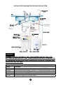
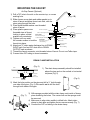
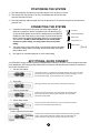
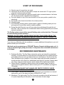
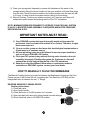
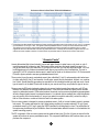
Installation & Service Manual
5-Stage Reverse Osmosis Drinking Water System
WQA GOLD SEAL:
This System Conforms to (WQA S-300) for the reduction of TDS, Pentavalent Arsenic, Barium, Cadmium, Chromium +6, Chromium +3, Copper, Fluoride, Lead, Radium (226/228), Selenium and Turbidity as verified and substantiated by test data.
®
Congratulations on choosing the PROLINE®
5-Stage Reverse Osmosis (RO) Drinking Water System
This high quality unit has been designed to fit under most kitchen and wet-bar
sinks. We suggest that you carefully review the following information booklet
before you attempt to install the reverse osmosis system.
Your Reverse Osmosis system is a highly sophisticated machine. We strongly
recommend using only trained & experienced technicians for installation and
troubleshooting. To locate the closest authorised service technician contact
your dealer or visit us at www.waterworldusa.com.
If you decide to install the unit yourself, please follow these installation
instructions, which have been simplified with color coded tubing. All your
local plumbing codes and regulations must be followed while installing your
RO system. For installation assistance, contact your local dealer.
Tools Required:
1) Hand drill for faucet hole. Use the appropriate 7/8” drill bit for the
surface you are drilling:
A) Titanium bit for metal sinks.
B) Glass and tile bit or Relton cutter for porcelain sinks.
C) Diamond core bit for granite.
2) Phillips head screwdriver.
3) Adjustable crescent wrench.
4) Basin wrench.
5) ¼” drill bit for drain clamp.
Your local dealer
1
INSTALLATION DIAGRAM FOR PROLINE GOLD SYSTEM
3/8” red tubing
to drain clamp
(Fig. 1)
1/4” red tubing
from flow restrict
to air gap
WARNING:
CONNECT YOUR SYSTEM TO THE COLD WATER SUPPLY ONLY. DO
NOT USE WATER SUPPLY THAT IS MICRO-BIOLOGICALLY UNSAFE, OR
OF UNKNOWN SOURCE WITHOUT ADEQUATE DISINFECTION BEFORE
OR AFTER THE SYSTEM.
Color Coded Tubing
Tubing
Directions
1/4” Green
3/8” Blue
3/8” Yellow
1/4” Red
3/8” Red
Feed water supply line to inlet. Feed ball valve labeled “TO FEED”
Carbon post filter elbow labeled “TO FAUCET” to center threaded shank of faucet
Carbon post filter tee labeled “TO TANK” to ball valve on storage tank
Flow restrictor labeled “TO DRAIN” to air gap 1/4” drain/barb inlet at faucet air gap
3/8” Barb on air gap to DC-38J Drain clamp
2
Installation Kit Contents
1. Color Coded Tubing:
Color Coded Tubing ( 5 coils, 4 colors)
¼’’ Green Tubing (approximately 8 feet)
¼’’ Red Tubing (approximately 6 feet)
3/8’’ Yellow Tubing (approximately 6 feet)
3/8’’ Blue Tubing (approximately 6 feet)
3/8” Red Tubing (approximately 5 feet)
Note: The color coded tubing matches
the color coded plugs on the PROLINE® RO unit.
color tubing
2. SV-01:
SV-01 (Self Piercing Saddle Valve) for tapping
into cold water supply by piercing a hole in to copper
tubing. (See figure # 3)
SV-01
AD-4BC-3W
3. BV-2BC (Chromed Ball Valve NPT ¼’’) and
AD-4BC-3W (Chromed Adapter NPT ½’’) are used for
tapping into cold water supply at the top of undersink . If
you have a vinyl feed line or flexible metal feed line use
the BV-2BC and AD-4BC-3W. (see figure #2)
BV-2BC
4. DC-38J
DC-38J (Drain Clamp) used for tapping into drainline for
discharge of the wastewater down the drain.
3/8” DC-38J (Drain Clamp)
5. Teflon Tape:
Teflon Tape is used on all threaded fittings to prevent
water leakage. Eight rotations (layers) are adequate
when using Teflon tape to secure any threaded fittings.
The PROLINE® RO already has Teflon tape on all of
its fittings.
Teflon Tape
6. BV-103-EZ:
BV-103-EZ (Storage Tank Ball Valve 3/8’’). In normal
operation, the Storage Tank Ball Valve must be in the
“open” position. Add 8 layers of Teflon tape on top of
the Threaded tank outlet. Screw tank ball valve
securely on threaded 1/4” port.
BV-103-EZ
7. Release Tool:
Release Tool (Quick Connect Release Wrench) allows
easier disconnecting of tubing ¼’’ and 3/8’’ from quick
connect fittings. Push release tool against collet of
quick connect fitting and pull the tubing out of the
fitting.
Release Tool
8. WR-1W :
WR-1W (White Wrench) Make sure the black rubber
O-ring is properly in place in the filter housing after
changing filters following any maintenance.
WR-1W
9. 6FC6:
6FC6 (Faucet connector) to connect the faucet with
blue 3/8’’ tubing coming from the post filter labeled
TO FAUCET.
6FC6
3
TAPPING INTO THE COLD WATER LINE
A - (Using the water supply adaptor Part # AD-4BC-3W & BV-2BC)
For flex metal or plastic line.
NOTE: The Proline® drinking water system must be connected to the COLD water
supply only.
1) Turn off the cold water supply to the sink faucet by locating the round or oblong
handle and turning clockwise until the water supply is off.
NOTE: If the cold water shut off valve fails to turn off the water, the house supply can
be turned off at the main water supply.
2) The water supply adapter (Fig. #2) may be installed at the faucet connection
(Fig. 2)
Base of the
cold water faucet
Apply teflon tape here
Flat washer
(inside supply adaptor)
Ball valve
BV-2BC
1/4” nut
Water supply adapter
AD-4BC-3W
1/2” threaded nut
with built in washer
Cold water supply
3) Disconnect the 1/2” threaded nut from the base of the faucet on the cold water
side. Place the flat washer inside the female end of the water supply adapter.
Screw on the base of the cold water faucet.
4) Re-connect the 1/2” threaded nut onto the male threads of the adapter. “DO
NOT USE TEFLON TAPE ON THIS THREAD, RUBBER WASHERS WILL SEAL
THE CONNECTIONS”.
5) Place Teflon tape on the 1/4” male threads of the ball valve supplied with the
adapter. Screw the ball valve into the 1/4” female port on the side of the adapter.
6) Remove the 1/4” nut from the ball valve, place the nut over the 1/4” Green tubing,
insert the tubing onto the barbed connection of the ball valve and tighten into
place with the 1/4” nut.
4
TAPPING INTO THE COLD WATER LINE
B - (Using self-piercing saddle valve Part # SV-01)
NOTE: This valve is designed for standard copper lines. If your cold water line is not
plumbed with copper line, use water supply adapter AD-4BC-3W & BV-2BC.
1) Turn off cold water supply under the sink and install the saddle valve to the cold line.
Clamp onto a smooth section and tighten valve bolt securely.
2) Turn the valve handle clockwise so that it pierces the copper cold water line.
3) Install the ¼’’ green tubing from the first stage filter to the saddle valve (Fig. #3).
*Do not over tighten brass nut
Cold water line
Valve bolt
(Fig. 3)
Plastic ferrule
Valve handle
Brass nut
Brass insert
NOTE: All local plumbing codes must be followed to ensure proper installation and
use of your PROLINE® system.
NOTE: Use brass insert and plastic ferrule when connecting tubing to saddle valve.
Cold Water Supply Valve (Figure #3)
CAUTION: A pressure regulator is recommended for feedwater pressure above 80 psi.
5
DRILLING THE HOLE FOR THE FAUCET
NOTE: SAFETY GLASSES SHOULD BE WORN TO PROTECT YOUR EYES WHILE
DRILLING THE FAUCET WHOLE.
1) For best results, a 7/8” drill bit should be used to drill a hole into your sink for the
auxiliary faucet.
2) Carefully select the faucet location making sure it will have a neat water fall
pattern and that the faucet stud will be accessible from below once the whole is
completed.
3) For Porcelain Sink: Before starting the drill motor, apply firm downward
pressure on the bit until a crunching occurs. This will help keep the drill from
moving when starting the hole. Use a special porcelain hole cutter.
4) For Stainless Steel Sink: Before using 7/8” bit, an indent should be made with
a center punch to keep the drill bit from moving. A small pilot hole will also aid the
7/8” drill bit.
5) For best results, keep steady firm pressure while drilling the hole. Too little
pressure during the start will cause excess wear on the bit and progress will be
slow.
6) Once the hole is complete, clean the area of metal chips and roughness around
the hole. Metal chips will stain porcelain.
For granite use a special diamond core bit only, help cool bit with water.
Warning: It is highly recommended for granite or slate countertops, to use the
assistance of a trained professional to drill the hole for the faucet. Serious damage
can occur to the counter if done by an inexperienced person.
6
MOUNTING THE FAUCET
Air Gap Faucet (Optional)
1) Drill a 7/8” hole in the sink or the counter top, or use an
(Fig. 4 B)
existing hole.
2) Slide chrome cover plate and rubber gasket on to
stem of faucet and place faucet onto sink, with the
stem going through the hole.
3) Place metal slotted washer over threaded
Rubber gasket
stem of faucet.
Chrome cover plate
4) Place plastic spacer over
threaded stem of faucet
Sink or counter top material
Slotted washer
locking in place, slotted
Darin Output
Plastic spacer
Drain line from air gap
washer onto countertop.
to drain clamp 3/8” red tubing
Metal washer
5) Tighten nut from under
Darin Input
Drain line to air gap
Faucet nut
the counter surface to lock the
1/4” red tubing
faucet into place.
Faucet connector
3/8” X 7/16”
6) Attach red ¼’’ drain water discharge line to DRAIN
Blue 3/8” tubing
INPUT barb. And red 3/8’’ drain line to DRAIN
OUTPUT barb as shown.
7) Thread the faucet connector onto threaded stem of faucet. Do not use Teflon tape.
8) Connect blue 3/8” tubing to faucet connector.
DRAIN CLAMP INSTALLATION
(Fig. 5)
Sink
Mount drain
saddle
at either location
1) The drain clamp assembly should be installed
above the trap and on the vertical or horizontal
tail piece (Fig. 5)
(Fig. 6)
Never mount here
2) Mark the hole position on the pipe and drill a ¼’’ hole through
one side of the pipe. (Fig. 6). Be careful not to drill the hole
through both sides of the pipe.
(Fig. 7)
3) Affix sponge provided with the drain clamp onto inside of clamp
piece matching the holes. The center hole on the sponge must
be removed.
4) Make sure to align drain saddle to drilled hole. Attach drain
clamp to drain pipe and tighten the two screws evenly (Fig. 7)
5) Connect the 3/8” red tubing to the drain clamp.
7
POSITIONING THE SYSTEM
1) The head assembly will stand up in the sink cabinet or can be hung on screws.
2) The storage tank may be laid on its side. The bladder tank will function both
ways horizontal and vertical.
3) The head assembly and/or storage tank may be placed up to 10 feet from the point of use with some
pressure loss.
CONNECTING THE SYSTEM
1)
Compression fitting may be found on the water supply adapter. To
make the connections, slide a compression nut onto the tubing (Fig.
8). Slip the white plastic sleeve onto the tubing with the beveled end
towards the end of the tubing. Insert a brass or plastic insert into the
tubing, bottom the tubing into the fitting, slide the nut up and tighten
with a wrench. DO NOT OVER TIGHTEN. Do not use the brass
sleeves on plastic tubing, use only plastic sleeves on plastic
tubing.
2)
The plastic fitting on the drain clamp is connected by slipping the plastic
nut onto the tubing. Bottom the tubing into the drain clamp and tighten
firmly without tools.
3)
See page 2 for connection diagram on color coded tubing.
Connector
White Plastic Sleeve
Brass Insert
Compression nut
Plastic Tubing
(Fig. 8)
EZ FITTINGS- QUICK CONNECT
Your PROLINE® reverse osmosis system is equipped with EZ fittings. The quick connect fittings feature leak
proof installations. EZ Fittings provide efficient quick connection and disconnection resulting in reduction of
service time and labor cost.
1 Cut tube into square
Cut the tube square. It is essential that the outside diameter be free of score marks
and that burrs and sharp edges be removed before inserting into fittings. For soft
thin walled plastic tubing, we recommend the use of a tube insert.
2 Insert tube
Fitting grips before it seals. Ensure tube is pushed into the tube stop.
3 Push up to tube stop
Push the tube into the tube stop. The collet (gripper) has stainless steel
teeth which hold the tube firmly in position while the ‘O’ ring provides a
permanent leak proof seal.
4 Pull to check secure
Pull on the tube to check that it is secure. It is a good practice to test the
system prior to leaving site and/or before use.
Disconnecting
Push in collet and remove tube
Push on collet
Pull on tubing
To disconnect, ensure the system is depressurized before removing the tube.
Push in collet squarely against face of fitting. With the collet held in the
position, the tube can be removed. The fitting can there be re-used.
(Fig.9)
8
START UP PROCEDURE
1) Check to see all connections are made
2) Check that the pre-filter and pre-carbon sumps are secure with “O” rings in place
using the housing wrench provided.
3) Slowly turn on the water by turning the needle valve counterclockwise or ball valve
1/4 turn,where handle is parallel to the tubing line.
4) The valve handle on top of the tank should be in the open position, parallel to the
valve body.
5) The handle of the faucet should be in the closed position.
6) Check for leaks.
7) The PROLINE® drinking water system makes 2 gallons of drinking water per hour
and requires 2 hours before water is readily available.
8) During this initial fill period, you will hear water being discharged through the red
drain line. This is normal as the contaminated water is being rejected by the reverse
osmosis membrane.
The Proline system comes with a manual flushing valve on the drain line. This must
be closed during normal operation.
WARNING: DO NOT DRINK WATER FROM THE FIRST TANK PRODUCED BY THE
SYSTEM. DISCHARGE THE WATER FROM THE STORAGE TANK BY OPENING THE
FAUCET. DISCHARGING MIGHT TAKE UP TO 15 MIN.
If you have any difficulties with the installation, or require additional information on your unit
please consult your local dealer.
We thank you for purchasing our PROLINE® Reverse Osmosis drinking water unit. In
order to maintain high quality pure water, it is important that scheduled maintenance
be followed.
RECOMMENDED MAINTENANCE
1) Sediment Pre-filter: The Pre-Filter protects the system and should be maintained
regularly. The snow-white Pre-Filter should be changed when the outside discolors
to a cardboard brown color and before the inner core discolors. The life of the PreFilter will depend upon condition of your water supply and should be checked at 3
month intervals until a filter life is established (average life 6 months). Always make
sure that o-rings are seated properly inside sumps before tightening canisters.
2) Carbon Blocks: Designed to reduce chlorine from the water supply, as well as
organic and inorganic substance before entering the TFC membrane (average life
12 months).
NOTE: ALWAYS MAKE SURE THAT O-RINGS ARE SEATED PROPERLY INSIDE
SUMPS BEFORE TIGHTENING CANISTERS.
3) Post-Carbon: The post-filter should be changed when you experience an unusual
taste and/or odor to the water and has a nominal life of 1 year.
4) Membrane: The high quality Thin Film Composite membrane should last between 2
to 4 years depending on the quality of your local water & water usage.
9
5) Drain your storage tank frequently to ensure the freshness of the water in the
storage tank by lifting the faucet handle into the open position until water flow stops
from the tank. Return the faucet handle to the closed position and the tank will refill
in 2 hours. It is best to drain the system before retiring for the evening
6) Manual Flushing: Flushing your system routinely (for 5 minutes each time) will
enhance the performance and prolong the life of the TFC membrane.
NOTE: MINIMUM PRESSURE REQUIRED TO OPERATE YOUR PROLINE® SYSTEM
IS 40 PSI. A BOOSTER PUMP ASSEMBLY IS REQUIRED WHEN FEED PRESSURE
DROPS BELOW 40 PSI.
IMPORTANT NOTES-MUST READ:
1) Your PROLINE® system has been thoroughly tested and inspected for
production, leaks, and shut-off functions at our factory. Therefore, it might
have some water in it.
2) Do not use this system on feed water that has biological contamination or
if feed water is of unknown source.
3) All local plumbing codes must be followed to ensure proper installation
and use of your PROLINE® RO System.
4) Flush your RO system (using manual flushing valve located on the unit
assembly) frequently. Flushing the system for 5 minutes at a time will
enhance the quality and prolong the life of the TFC membrane.
5) Should you require additional information or need further technical
assistance on PROLINE® system, contact your local dealer.
HOW TO MANUALLY FLUSH THE MEMBRANE
The Manual Flushing Device is located in between the Membrane Housing and the Post
Carbon on top of the Proline RO unit, containing the Flow Restrictor (FR-450) and the
straight ball valve in between the two “Y” fittings.
op
en clos
ed
ed
en clos
REVERSE OSMOSIS FLUSHING DEVICE
Flushing Instructions:
1) Close tank valve
2) Open faucet handle
3) Rotate ball valve to FLUSH position for 5 minutes
4) Open tank ball valve and close faucet handle (normal settings)
5) Return flush ball valve to IN SERVICE position
op
10
In service
(Closed)
Flush
(Open)
CHANGING THE FILTERS
CAUTION: ANY REPLACEMENT FILTERS OR MEMBRANES NOT RECOMMENDED BY THE FACTORY
CAN CAUSE SEVERE DAMAGE TO THE SYSTEM AND VOID ALL WARRANTIES.
MAINTENANCE
Before starting maintenance, check the reverse osmosis system for TDS reduction to determine if membranes
will or will not need to be changed.
If TDS reduction is less than 90% concentration, then the membrane should be replaced.
1) Shut off the water supply to the system.
2) Close storage tank ball valve.
3) Open the dispensing faucet to depressurize the system. (Allow 2 to 3 minutes).
4) Remove the filter housings by turning counter-clockwise.
5) Remove old filters and clean housings with a mild soap and water solution.
6) Check o-rings for deterioration and lubricate with an approved FDA silicone lubricant for o-rings or replace
if needed.
7) Insert the appropriate new filters inside housings and replace them by mounting them in to position. Make
hand tight plus 1/8 to ¼ turn with housing wrench. DO NOT OVER-TIGHTEN. Over-tightening will cause
cracks and leaks if not careful.
CAUTION: ALWAYS MAKE SURE THAT “O”-RINGS ARE SEATED PROPERLY INSIDE SUMPS BEFORE
TIGHTENING CANISTERS.
8) If a membrane needs changing, remove the inlet tubing to the housing, unscrew the cap, and pull the
membrane out using a needle nosed pliers. Clean the inside of the membrane housing with a mild soap
and water solution.
9) Lubricate the o-rings on the membrane permeate tube with an approved FDA silicone lubricant. Insert into
the housing with brine seal towards the opening. Make sure membrane is fully inserted and seated into
place.
10) Reseal the membrane housing with the cap and reconnect tubing.
11) To replace the carbon in-line post filter, remove the tubing and fittings at either end. Clean the old Teflon
tape off the threads and apply new tape. Screw the fittings into the new cartridge paying close attention
to the flow direction. Reinsert tubing.
Instructions and Information
Model: PROLINE-GOLD PRODUCTION: 43.5 LPD (11.5 GPD)
Contact your local dealer for replacement filters, or you may call 281-933-5777 to locate a dealer in your
area.
This reverse osmosis system discharges 450 milliliters per minute while the tank is filling.
This reverse osmosis system contains replaceable treatment component, critical for effective reduction of
total dissolved solids. The product water shall be tested periodically to verify that the system is performing
properly.
This reverse osmosis system conforms to WQA S-300 for reduction of TDS as verified and substantiated by
test data.
Replacement treatment components:
1st Stage: Item # 32023
2nd & 3rd Stages: Item # 32-250-125-975
4th Stage: TW30-1812-50
5th Stage: K2540-BB
Waterworld USA, Inc.
10875 Fallstone Rd, Houston, TX 77099 (Tel: 281-933-5777)
11
Performance Data Sheet WQA S-300
Reverse Osmosis System
Model Number: PROLINE GOLD
Replacement treatment components:
1st Stage: Item # 93023
2nd & 3rd Stages: Item # 32-250-125-975
4th Stage: TW30-1812-50
5th Stage: K2540-BB
➣ Do not use with water that is microbiologically unsafe or of unknown quality without adequate disinfection
before or after the system. Systems certified for cyst reduction may be used on disinfected water that may
contain filterable cysts.
➣ This reverse osmosis system contains a replaceable treatment component critical for effective reduction
of total dissolved solids. The product water shall be tested periodically to verify that the system is
performing satisfactorily.
➣ This reverse osmosis system contains a replaceable component critical to the efficiency of the system.
Replacement of the reverse osmosis component should be with one of the identical specifications, as
defined by the manufacturer, to assure the same efficiency and contaminant reduction performance.
➣ While testing was performed under standard laboratory conditions, actual performance may vary.
➣ See page 15 of this manual for Manufacturer’s limited warranty.
➣ Efficiency rating means the percentage of the influent water to the system that is available to the user as
Reverse Osmosis Treated water under operating conditions that approximate typical daily usage.
➣ This system has been tested and shown to operate at its calculated recovery rating, or efficiency rating, or
both under standard test conditions.
➣ Chlorine in the influent water may affect the RO membrane polymers.
➣ See owner’s manual for complete installation/operation and maintenance requirements.
➣ Recovery rating means the percentage of the influent water to the membrane portion of the system that is
available to the user as reverse osmosis treated water when the system is operated without a storage
Daily production rate-
11.5 GPD
Recovery rate-
15.6%
Pressure Drop at Rated Flow-5psi
System weight-
21 lbs
Efficiency rating-
5.6%
System Dimension-
16x5x18
Min./max. pressure-
40-80 psi
Min./max. temperature-
39-100 f
Test parameters: 25°±1°C, 50 psi, and pH of 7.5
WQA GOLD SEAL:
This System Conforms to NSF/ANSI 58 (WQA S-300) for the reduction of TDS, Pentavalent
Arsenic, Barium, Cadmium, Chromium +6, Chromium +3, Copper, Fluoride, Lead, Radium (226/228),
Selenium and Turbidity as verified and substantiated by test data.
This system has been tested according to WQA S-300 for reduction of substances below. The concentration of the indicated substances in water entering the system was reduced to a concentration
less than or equal to the permissible limit for water leaving the system.
12
Performance Claims for Dow/Filmtec TW30-1812-50 Membrane
†
† This appliance has been tested for the treatment of water containing pentavalent arsenic (also known as As(V), As(+5), or arsenate)
at concentrations of 0.30 mg/L or less. This appliance reduces pentavalent arsenic, but may not remove other forms of arsenic.
This appliance is to be used on water supplies containing detectable free chlorine residual at the appliance inlet or on water
supplies that have been demonstrated to contain only pentavalent arsenic. Treatment with chloramine (combined chlorine) is not
sufficient to ensure complete conversion of trivalent arsenic to pentavalent arsenic. Please see the Arsenic Facts section.
“Arsenic Facts”
Arsenic (abbreviated As) is found naturally in some well water. Arsenic in water has no color, taste, or odor. It
must be measured by a laboratory test. Public water utilities must have their water tested for arsenic. You
can get the results from your water utility. If you have your own well, you can have the water tested. The local
health department or the state environmental health agency can provide a list of certified labs. The cost is
typically $15 to $30. Information about arsenic in water can be found on the Internet at the U. S. Environmental
Protection Agency website: www.epa.gov/safewater/arsenic.html.
There are two forms of arsenic: pentavalent arsenic (also called As(V), As(+5), and arsenate) and trivalent arsenic (also called As(III), As(+3), and arsenite). In well water, arsenic may be pentavalent, trivalent, or a combination of both. Special sampling procedures are needed for a lab to determine what type and how much of each
type of arsenic is in the water. Check with the labs in your area to see if they can provide this type of service.
Reverse osmosis (RO) water treatment systems do not remove trivalent arsenic from water very well. RO systems are very effective at removing pentavalent arsenic. A free chlorine residual will rapidly convert trivalent
arsenic to pentavalent arsenic. Other water treatment chemicals such as ozone and potassium permanganate
will also change trivalent arsenic to pentavalent arsenic. A combined chlorine residual (also called chloramine)
may not convert all the trivalent arsenic. If you get your water from a public water utility, contact the utility to
find out if free chlorine or combined chlorine is used in the water system.
The PROLINE® system is designed to remove pentavalent arsenic. It will not convert trivalent arsenic to pentavalent arsenic. The system was tested in a lab. Under testing conditions, the system reduced 0.30 mg/L (ppm)
pentavalent arsenic to 0.010 mg/L (ppm) (the USEPA standard for drinking water) or less. The performance of
the system may be different at your installation. Have the treated water tested for arsenic to check whether the
system is working properly.
The RO component of the PROLINE® system must be replaced every two (2) to four (4) years to ensure that the
system will continue to remove pentavalent arsenic. The component identification and locations where you can
purchase the component
13
TROUBLESHOOTING
SYMPTOM
UNIT FAILS TO PRODUCE
WATER
MILKY COLORED WATER
NOISE FROM FAUCET
UNIT PRODUCES WATER BUT
ONLY GETTING A SMALL
AMOUNT OUT OF TANK.
CAUSE
CORRECTION
1) WATER SUPPLY IS TURNED OFF.
1) TURN WATER SUPPLY ON.
2) CHECK TO MAKE SURE FEED VALVE IS NOT
CLOGGED.
2) NOT ENOUGH WATER PRESSURE TO SYSTEM.
1) CHECK FEED WATER PRESSURE. MUST BE AT
LEAST 40PSI.
3) PREFILTERS CLOGGED.
1) CHANGE PREFILTERS.
4) FLUSH VALVE ON UNIT IS IN THE OPEN POSITION.
1) CLOSE THE FLUSH VALVE.
1) AIR IN SYSTEM
1) AIR IN SYSTEM IS A NORMAL OCCURRENCE
WITH INITIAL STARTUP OF THE RO SYSTEM. THIS
MILKY LOOK DISAPPEARS DURING NORMAL USE
WITHIN1 TO 2 WEEKS.
1) AIR GAP FAUCET
1) NORMAL WITH AIR GAP FAUCET
2) LOCATION OF DRAIN SADDLE
1) RELOCATE THE DRAIN TO HORIZONTAL
3) RESTRICTION IN DRAIN LINE
1) BLOCKAGE SOMETIMES CAUSED BY DEBRIS
FROM GARBAGE DISPOSAL OR DISHWASHER
1) TANK BALL VALVE IS IN THE CLOSED POSITION.
1) OPEN THE TANK BALL VALVE.
2) PREFILTERS ARE CLOGGED.
1) CHANGE PREFILTERS.
3) MEMBRANE IS FOULED.
4) NO AIR PRESSURE IN TANK.
NOTES:
1) CHANGE MEMBRANE.
2) FIND REASON FOR FOULING. TO PREVENT
FUTURE OCCURRENCE.
1) CHECK AIR PRESSURE IN TANK. MUST BE 8-10 PSI
WHEN COMPLETELY EMPTY OF WATER.
2) BLADDER IN TANK IS RUPTURED. TANK MUST BE
REPLACED WITH NEW ONE.
5) CHECK VALVE ON PRODUCT SIDE NOT
HOLDING.
1) REPLACE CHECK VALVE ON UNIT.
1) LOW WATER PRESSURE
1) MAKE SURE PUMP IS WORKING
2) CRIMPS IN TUBING
2) MAKE SURE TUBING IS STRAIGHT
3) CLOGGED PRE-FILTERS
3) REPLACE PRE-FILTERS
4) FOULED MEMBRANE
4) REPLACE MEMBRANE
1) POST CARBON IS DEPLETED
1) REPLACE POST CARBON
2) FOULED MEMBRANE
2) REPLACE MEMBRANE
3) SANITIZER NOT FLUSHED OUT
3) DRAIN STORAGE TANK AND REFILL OVERNIGHT
1) CLOGGED FLOW RESTRICTOR
1) REPLACE FLOW RESTRICTOR
1) TUBING CONNECTED INCORRECTLY
1) MAKE SURE DRAIN AND PRODUCT LINES ARE
CONNECTED PROPERLY.
2) MEMBRANE FAILURE
1) CHLORINE MAY HAVE PASSED THROUGH TO
MEMBRANE. REPLACE MEMBRANE AND CHANGE
PREFILTERS.
2) MEMBRANE MISHANDLED OR STORED IMPROPERLY. REPLACE MEMBRANE.
1) AUTO SHUTOFF NOT CLOSING.
1) REPLACE AUTO SHUTOFF.
2) CHECK VALVE ON PRODUCT SIDE NOT
HOLDING
1) REPLACE CHECK VALVE.
1) FITTINGS ARE NOT TIGHTENED
1) TIGHTEN FITTINGS AS NECESSARY
2) MISSING O-RINGS
2) CONTACT LOCAL DEALER
3) MISALIGNMENT OF HOLE IN DRAIN SADDLE
3) REALIGN DRAIN SADDLE
SLOW PRODUCTION
WATER TASTE OR SMELL
OFFENSIVE
NO DRAIN WATER
UNIT PRODUCING
WATER TOO RAPIDLY
WATER RUNS TO DRAIN ALL
THE TIME
LEAKS
Your Reverse Osmosis system is a highly sophisticated machine. We strongly recommend using only trained
& experienced technicians for installation and troubleshooting. To locate the closest authorised service technician contact your dealer or visit us at www.waterworldusa.com.
14
PROLINE® LIMITED WARRANTY
The PROLINE® reverse osmosis system is warranted to be free from defects in materials and workmanship under normal
use within the operating parameters listed below. For a period of five years from the date of purchase PROLINE® will
repair or replace any part of the reverse osmosis system with the exception of the filters and electrical components if any.
CONDITIONS OF WARRANTY:
PROLINE® assumes no responsibility for incidental or consequential damages; for damages arising out of misuse of
the product or the use of any unauthorized attachment; for damages resulting from improper installation or for damages
resulting from the use of the product with a defective plumbing system.
In no event shall PROLINE® be liable for any direct, indirect, special, punitive, incidental, exemplary or consequential
damages, attorney’s fees or any damages whatsoever, even if PROLINE® has been previously advised of the possibility
of such damages, whether in an action under contract, negligence, or any other theory, arising out of or in connection with
the use, inability to use, or performance of the PROLINE ® system.
PROLINE® is not responsible or liable for damage to any part of the PROLINE® system because of misuse; misapplication; negligence; alteration; accident; installation; neglect; misapplication; physical damage; fouling and/or scaling of the
membrane by minerals; sediment; bacterial attack; or operation contrary to our instructions, incompatibility with accessories not authorized for use with the system, or damage caused by freezing, flood, fire, or Act of God.
In no event shall PROLINE® its subsidiaries or affiliates, or their respective officers, directors, employees, representatives, dealers or agents be liable for special, incidental, consequential, punitive, indirect, or other special damages, including but not limited to, loss of data, use, or profits, however caused, whether for breach of contract, negligence or otherwise, and whether or not PROLINE® has been advised of the possibility of any such damages.
PROLINE® assumes no warranty liability in connection with this reverse osmosis system other than that specified herein.
This warranty is in lieu of all other warranties, expressed or implied, including warranties of fitness for a particular purpose.
WARRANTY SERVICE:
PROLINE® will provide warranty service under the following conditions:
1) Contact your local dealer who will obtain return authorization instructions.
2) Ship the unit or part freight prepaid for warranty evaluation or service with RMA # written on package. Systems or
parts covered under the warranty shall be repaired (or, at our option replaced) and returned without charge.
CONDITIONS FOR OPERATION:
Operating Parameters:
System Pressure
Temperature
PH Range
Maximum feed TDS level
Maximum Turbidity
40-80psi
4-38 C (39-100 F)
3.0 to 11.0
2000 ppm
1.0 Net Turbidity (NTU)
Chemical Parameters:
Maximum Hardness
350mg/L (20 gpg)
Maximum Iron (Fe)
0.1 mg/L
Maximum Manganese (Mn)
0.05 mg/L
Maximum Hydrogen Sulfide (H2S)
0.00 mg/L
Maximum Chlorine (Cl2)
2.00 mg/L
A pressure regulator is recommended for feedwater pressure above 80 psi.
Although TFC membranes are designed for non chlorinated feed supply, your PROLINE® RO system is equipped with double carbon pre-filtration for chlorine reduction prior to the TFC membrane.
15
Serial #