1
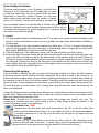
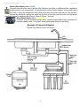
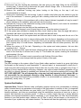
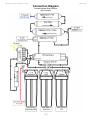
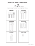
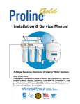
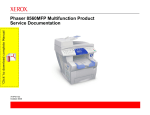
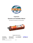
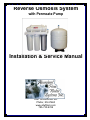
Reverse Osmosis System
with Permeate Pump
Installation & Service Manual
2261 Schoenchen Rd.
Pfeifer, KS 67660
www.afwfilters.com
785-735-9769
Important Information
Date Purchased:
Date Installed:
Replacement Filter Set:
_______________________
_______________________
_______________________
Replacement filters available on our website: www.afwfilters.com
A PDF version of this manual is available at - support.afwfilters.com/service-manuals/rosystems.php
Maintenance Log:
Detailed information & instructions on system maintenance can be found in the maintenance section,
recommended maintenance intervals are as follows:
System
Filter Set
Filters: Every 6 months for most homes, at least once a year
5-stage
ROFK5
6-stage w/ UV
UV Bulb: Every 12 months (on systems equipped with a UV light)
6-stage w/ pH
ROFK6
7-Stage w/ UV+pH
Sanitization: Once a year, more often if bacteria present
6-Stage w/ DI
ROFK7
7 Stage w/ UV+DI
Membrane: Varies from 2-4 years, at least every 4 years
7-Stage w/ DI+pH
ROFK8
8-Stage w/ UV+DI+pH
UV Bulb
UVB1
Date
Filters Replaced
Sanitized
[ii]
UV Bulb
Membrane
Table of Contents
IMPORTANT INFORMATION ..................................................................................................................II
MAINTENANCE LOG .................................................................................................................................. II
TABLE OF CONTENTS ..........................................................................................................................III
PRE-INSTALLATION PREPARATION ....................................................................................................1
BRIEF TECHNICAL SUMMARY OF THE FILTRATION PROCESS ........................................................................ 1
WATER PURIFICATION SUMMARY: ............................................................................................................. 1
SYSTEM MAINTENANCE SUMMARY: ........................................................................................................... 1
PRE-INSTALLATION CHECK LIST................................................................................................................ 2
PARTS CHECKLIST .................................................................................................................................. 3
SYSTEM INSTALLATION ........................................................................................................................3
FAUCET INSTALLATION ............................................................................................................................. 3
STORAGE TANK: ..................................................................................................................................... 4
FEED W ATER INSTALLATION: .................................................................................................................... 5
DRAIN SADDLE INSTALLATION: ................................................................................................................. 6
CONNECTING THE SYSTEM: ...................................................................................................................... 6
EXAMPLE OF CONNECTED SYSTEM ........................................................................................................... 7
SYSTEM START UP: ...............................................................................................................................8
SYSTEM MAINTENANCE ........................................................................................................................9
FILTERS: ................................................................................................................................................ 9
MEMBRANE:.......................................................................................................................................... 10
O-RINGS: .............................................................................................................................................. 11
SYSTEM SANITIZATION: .......................................................................................................................... 11
TROUBLESHOOTING ...........................................................................................................................13
QUICK TROUBLESHOOTING GUIDE .......................................................................................................... 13
TRACING W ATER FLOW ......................................................................................................................... 14
CONNECTION DIAGRAM ......................................................................................................................15
REVERSE OSMOSIS SYSTEM LIMITED WARRANTY ........................................................................16
[iii]
NOTES
©Abundant Flow Water Systems, Inc. 2009
Revised 9/09
Pre-installation Preparation
IMPORTANT: Read through the entire instruction manual before beginning installation.
Abundant Flow Water is not responsible for any damage, injury, or monetary loss incurred from
failure to read and follow instructions.
Brief Technical Summary of the Filtration Process
Water enters the filter system and passes through a series of pre-filters. The sediment filter removes
particulates such as dirt and sediment. The GAC (granular activated carbon) removes a wide range of
chemicals (including chloramines), tastes, and odors. The carbon block filter removes chlorine and any
tastes and odors the GAC filter might miss. The pre-filters protect the membrane and should be
changed regularly to ensure maximum performance and membrane life. (NOTE: Some special order
systems may have different pre-filters). The water is then purified using a process called reverse
osmosis (RO). As the heart of the purification system, the RO process uses a semi-permeable, spiralwound membrane to separate and remove dissolved solids, organic, pyrogens, sub-micron colloidal
particles and bacteria from the water. Feed water is delivered under pressure at about 60 PSI through
the permeator where water permeates the minute pores of the membrane and is delivered as purified
water. Impurities in the water are concentrated in the reject stream and flushed to drain. The RO
Membrane is capable of removing 90% to 95% of contaminates present in the water. The optional UV
filter uses ultra violet light to destroy bacteria and viruses. The optional DI filter is composed of a mixed
bed of resin beads, some positively charged, some negatively charged. These charged resins
effectively strip the remaining impurities from the water, effectively removing 99%+ of contaminants!
The post filter gives a final polishing to ensure clean tasting water. The optional inline pH/mineral filter
ensures a neutral pH and adds beneficial minerals back into the water.
Permeate Pump Operation:
On standard RO systems, the permeate (good) water produced by the membrane is stored in a
pressurized storage tank. As the tank fills pressure increases, pushing back on the membrane and
increasing the amount of waste water produced. The permeate pump negates the back pressure on the
membrane by using the pressure of the waste water to push the water from the membrane into the
storage tank, improving efficiency and decreasing waste water. Used in combination with the 90% auto
shut off valve, the permeate pump also fills the tank fuller than standard systems. NOTE: During
operation a clicking sound may be heard, this is normal.
Water Purification Summary:
Stage 1: Sediment Filer - Traps dirt, sediment, & particulates
Stage 2: GAC (granular activated carbon) Filter - Chloramines, Tastes, Chemicals, & Odors
Stage 3: Carbon Block Filter - Chlorine, Tastes, Chemicals, & Odors
Stage 4: RO TFC Membrane - 90-95% of contaminates
Stage 5: Optional UV Filter - Kills bacteria, viruses, & cysts
Storage: Pressurized Tank
Stage 6: Optional DI Filter - Removes 99% of any remaining contaminates
Stage 7: Inline Post Filter - Polishing filter to ensure clean, fresh tasting water
Stage 8: Optional pH Filter - Neutralizes acidic water and adds calcium and magnesium
Delivery: Standard RO Faucet
System Maintenance Summary:
Filters: Filter maintenance will vary depending on water quality and water usage. For most homes with
average water quality and usage, every 6 months is usually sufficient. For higher water use and/or
dirtier water, more frequent filter changes may be needed. Filters need to be changed at least once a
year. If equipped, the UV bulb should be changed every 12 months. Use the chart in the important
[1]
©Abundant Flow Water Systems, Inc. 2009
Revised 9/09
information section for help determining the filter set needed for your system. Replacement filters can
be ordered online at products.afwfilters.com.
Membrane: Average membrane life varies from 2-4 years depending on a number of factors. Reduced
water production or quality may indicate a fouled membrane, or a TDS meter can be used to monitor
the membrane. The membrane should be changed at least every 4 years.
Sanitization: It is recommended that the system is sanitized once a year to prevent bacterial build up
and ensure a clean system. Even in homes with no known bacteria problem or bacteria prevention in
place it is a good idea to sanitize the system. If used in a home with a know bacteria problem, more
frequent sanitization may be a good idea.
Pre-installation Check List
1. Read through and familiarize yourself with these instructions and the installation process. This will
ensure you have the proper tools, parts, and abilities to install the system before beginning, rather
than having to stop halfway through because you are missing something or are unable to do
something.
2. Check local plumbing codes and follow any that apply to your installation. Going against plumbing
codes is illegal, and can cause problems. AFW is not responsible for any problems resulting from
improper installation or installation that is a violation of local plumbing codes.
3. Determine installation locations, including feed water supply, drain, faucet, filter system, and storage
tank. Ensure you have room for everything, and plan room for future filter changes.
4. Familiarize yourself with the quick connect fittings. Your system uses quick connect fittings. There is
a collet ring at the end of the fitting that grips the tubing and holds it in place. To remove, simply hold
the collet ring against the fitting and pull the tubing out. To replace tubing, just push it into the fitting, it
will slide in easily about 1/4” then stop, apply a little more pressure and it will slip in another 1/8” or so
and seal in place.
5. Familiarize yourself with any purchased upgrade kits. If you ordered any kits to upgrade your system,
read through the instructions on how to install it, as it is usually easier to install any upgrades before
installing the system.
6. Check to ensure there are no missing parts. Use the parts checklist on the following page to make
sure all the parts listed are present. If anything is missing, call us and we will get replacements out as
soon as possible.
7. Assemble the tools you will need. Depending on where the system is being installed and the
plumbing, the tools needed may vary. You will need a Phillips head screwdriver, drill, wrenches,
pliers & Teflon tape. You will also need a sharp knife or scissors to cut the tubing (when cutting
tubing, ensure the end is smooth and straight, this will ensure a good seal and prevent leaks). This
list is just a start, reading through the instructions and determining where you are installing the
system will give you a better idea of everything needed.
8. Ensure the following conditions are met:
Feed Water
Minimum
Maximum
Condition
Inlet Pressure
40 psi
80 psi
Temperature
40° F
100° F
pH Level
3
11
TDS Level
0 ppm
2000 ppm
For pressure less than 40psi a booster pump will be required. If pressure is less than 50psi a booster
pump or permeate pump is recommended. If other conditions are not met contact us for a solution.
NOTE: Failure to meet the above conditions will void the warranty on the system.
[2]
©Abundant Flow Water Systems, Inc. 2009
Revised 9/09
Parts Checklist
In addition to the RO system, faucet, storage tank, and UV transformer (if a UV was ordered), you
should have the following parts (pictures and descriptions represent the most common style, actual
style may vary):
Tank Ball Valve - White & blue plastic valve with female threads and quick connect fitting.
Installed on storage tank, valve is open when handle is inline with tubing.
Slip Joint Adapter - Metal fitting with male & female ends, smaller female threads on one
side for attaching the angle ball valve. Fits most standard faucet shanks for easy feed water
installation.
Angle Ball Valve - Blue handled metal valve with male threads and compression fitting.
Attaches to slip joint adapter and feed water line, valve is open when handle is inline with
tubing.
Drain Saddle - White plastic clamp with quick connect fitting, 2 bolts with nuts, and rubber
seal. Clamps around the drain pipe and connects to the waste water line.
Quick connect faucet fitting - White plastic fitting with female threads and quick connect
fitting. Connects to the RO faucet shank and product water line.
A plastic wrench (for tightening and removing the filter housings) is also included and 2 screws for
attaching the mounting bracket to the mounting location may be included.
If you purchased any upgrade kits, please refer to the instructions that came with it for the parts that
should be included with it.
Once you have read through the entire instruction manual and familiarized yourself with the installation
process, you may proceed with installing the system.
System Installation
Faucet Installation
Locate the installation point for the faucet; you will need a hole at least 1/2” in diameter for the RO
faucet shank. If the sink has a sprayer the RO faucet may be installed in the hole used for the sprayer,
simply disconnect the sprayer and plug the sprayer connection. If the sprayer hole is not an option you
will need to drill a hole. To drill a hole, determine where it will be located before starting. You will need a
2” flat surface no more than 2” thick. Ensure the chosen location will not interfere with anything below,
and position the faucet so it will empty into the sink and can swivel freely for convenience. Once you
have confirmed your faucet location, proceed with drilling the hole in your sink.
Porcelain, Enamel, or Ceramic on Metal
Be careful when drilling though porcelain, enamel or ceramic sinks, drill slowly to prevent chipping or
scratching, and be sure to wear proper safety equipment to protect yourself.
1. Mark the center of the hole with a pencil, marker or other marking device
[3]
©Abundant Flow Water Systems, Inc. 2009
Revised 9/09
2. Using a 1/4” masonry bit, carefully (using a slow speed and light
pressure) drill a pilot hole through the sink. If drilling through a
ceramic on metal sink, stop when you reach the metal portion, switch
to a 1/4” metal cutting bit and continue.
3. Continue to enlarge the pilot hole with larger masonry bits (& metal
cutting bits if applicable) until the hole is 1/2".
4. Clean up any rough or sharp edges.
Stainless Steel or Cast Iron
Be careful when drilling stainless steel or cast iron, drill slowly to
prevent scratching, and be sure to wear proper safety equipment for
protection.
1. Mark the center of the hole with a pencil, marker or other marking
device
2. Using a 1/4” metal cutting bit, carefully drill a pilot hole through the
sink.
3. Continue to enlarge the pilot hole with larger metal cutting bits until
the hole is 1/2"
4. Clean up any sharp edges
Note: Air gap faucets are required by some local plumbing codes.
These faucets require a 1-1/4" hole in the sink rather than the 1/2" hole
required by the standard RO faucet. If a large enough hole (1-1/4") is
not already available, special tools (such as a chassis punch or a
Relton cutter) may be required. Contact your local plumber or
contractor if you are unable to make the required hole yourself. If an air
gap faucet is required, we provide a number of different styles and
colors; contact us for pricing and availability.
Once the faucet location has been prepared, move on to the next step: Mounting the Faucet.
Mounting the Faucet:
1. Remove all parts from the RO faucet shank. Using Figure 1, gather the pieces shown. NOTE: The
diagram is for the standard RO faucet, an upgraded faucet may look slightly different than the one
pictured, but the parts should be similar.
2. Place color matched washer onto faucet shank, followed by the small rubber washer. Position the
faucet in the mounting location by sliding the shank through the mounting hole.
3. On the underside of the mounting hole, slide the large rubber washer and locking washer in place,
then tighten the faucet nut in place until secure.
4. Once your system is installed, you can hook up the product line to the faucet. The best way to do so
is to wrap the bottom of the faucet shank with 6-7 wraps of Teflon tape, then attach the quick connect
faucet fitting. The product line will then push directly into the fitting. An alternate method of attaching
the line is to slide the line nut over the product line, followed by the ferrule, then push the insert into
the end of the line. Once that is done simply push the end of the product line into the bottom of the
faucet shank as far as it will go, then tighten the line nut to secure it in place.
Storage Tank:
As the RO system makes water it pushes it into a tank to store it, and a pressurized bladder in the tank
pushes it back out (through the same opening) when requested (such as opening the faucet). The large
male threaded fitting on one end of the tank is the inlet and outlet of the tank. A pressure valve on the
side of the tank (usually covered with a blue screw-on cap) is used only for checking and adding air to
the bladder. The tank is shipped with 4-6psi of air pressure in the bladder, and is sufficient in most
[4]
©Abundant Flow Water Systems, Inc. 2009
Revised 9/09
cases. Pressure may be increased to no higher than 10psi when the tank is empty, this will cause
water to come out of the faucet a little faster if so desired. NOTE: As the tank is emptied, pressure from
the faucet will decrease, this is normal.
To Prepare the Tank:
1. Wrap the threaded nipple on the end of the tank with 6-7 wraps of Teflon tape.
2. Install tank ball valve on prepared nipple, tightening hand tight only. Once your system is connected,
your tank line will connect to this fitting
Feed Water Installation:
1. The feed water assembly consists of a 1/2" slip joint adapter with 2 washers and an angle ball valve.
Locate these parts in the installation kit. If space permits, the angle valve should be installed into the
slip joint adapter before connecting the assembly to the feed water line (Note: Teflon tape must be
used on angle valve to prevent leaks).
2. Locate cold-water angle shut off valve underneath the sink, usually on the right side, and turn it off.
Open cold water faucet to release the pressure. On single handle faucets, the hot water may need to
be turned off to prevent any hot water from crossing over. If water continues to come out of the
faucet with angle valve turned off the main water supply will have to be turned off.
3. The slip joint adaptor is usually installed on the cold water faucet shank, but may be installed on the
cold water shut off valve. (Figure 2) If installing on the cold water shut off valve, an adapter will most
likely be required. Use the following instructions for your particular plumbing type.
Flex line Instructions
Loosen nut and separate cold water line from faucet shank. Insert the flat washer into the slip joint
adapter, and gently bend flex line so that the slip joint adapter fits onto faucet shank and tighten slip
joint adaptor to faucet shank. If washer in flex line is worn or damaged, replace before continuing to
prevent any leaks. Re-install cold water line onto slip joint adapter and tighten. (The cone washer is
not used in flex line installations)
Copper Instructions
Loosen nut and separate cold water line from faucet shank. You will
need to cut a piece of the copper tube about 3/4" to 1" (measure to
determine the exact cut needed) so the slip joint adapter can fit
between faucet and the copper line. Insert the flat washer into the
slip joint adapter and tighten onto cold water faucet shank. Insert
the cone washer into the slip joint adaptor and push the copper pipe
into the washer and adaptor and tighten down the compression nut.
Make sure you use plenty of Teflon tape on all connections.
4. Once the system is ready to be hooked up, the feed water line will
connect to the angle ball valve. To connect, place the nut and
ferrule (white plastic ring) over the feed water line, insert the line
into the angle valve, and tighten the nut. Alternately, if your angle
ball valve has a stem on it, slide the nut over the feed water line,
push the line onto the stem, and tighten the nut down (no ferrule is
used).
[5]
©Abundant Flow Water Systems, Inc. 2009
Revised 9/09
Drain Saddle Installation:
The drain saddle consists of two (2) halves, (one half has a
fitting on it), two (2) bolts with nuts, & a rubber seal. It is used
to direct the waste water from your system down the drain.
Depending on where the saddle is located, you may hear
water running down the drain when the system is making
water, this is normal. If the sound is annoying, the drain line
may be pushed farther in to help alleviate it. Please note, pushing the
drain line in farther than normal requires a good amount of force, as you
are forcing the tubing past the typical stopping point. If doing so, please
use caution to prevent any injuries.
To install:
1. The drain saddle should be installed above the “P” trap and on the vertical or horizontal tailpiece (see
figure 3). A horizontal location is ideal, as it is more likely the waste water will be heard if installed on
a vertical pipe.
2. The hole position on the pipe should be marked and drilled with a 1/4" bit. If using a horizontal pipe,
ensure the hole is made on the top of the pipe, so that standing water in the pipe will not leak into the
drain saddle. NOTE: Drill through one side of the pipe only!
3. Take the backing off of the rubber seal, center over the hole just drilled, and stick in place.
4. Position the half of the drain saddle with the fitting (the fitting half) over the hole in the drain pipe, then
position the other half (the back half) of the drain saddle on the opposite side of the drain. Place one
of the bolts through the fitting half through the back half and loosely thread the nut onto it. Repeat on
the other side. Position the fitting on the fitting half of the saddle over the drilled hole and seal, and
evenly tighten both nuts, being careful not to over tighten. Once your system is set up, the drain line
will connect to the drain saddle (Figure 4).
Connecting the system:
Once the faucet is installed, the tank is in place, the feed water adapter is in place, the drain saddle is
positioned, and the system location had been determined, the system is ready to be hooked up. To
make future filter changes easier, we recommend positioning the system in a location where filters can
be changed, (such as in front of the kitchen cabinet if installing under the kitchen sink) and hooking the
system up there, simply wrapping the extra tubing up and putting the system away during normal use.
This will allow you to pull the system out to change filters and will save time since the system will not
have to be unhooked.
Using the following pictures and descriptions and the color coded tubing to make the connections to the
system. Note: The pictures show blue plugs to make the connection easier to see, your system should
have color coded tubing inserted in them.
Please Note: Pictures are for reference only, actual fitting design and location may vary. The
connection is described and color coded tubing is used to make things as easy as possible. If still
unsure, feel free to contact us for assistance.
Feed Water Line – RED
Connects from the feed water ball valve (connected to the “IN” on the first (clear) filter
housing with the white sediment filter in it) to the angle ball valve on the feed water adapter.
To connect, place the nut on the line, push the line over the barb on the angle valve and
tighten the nut.
Tank Line – CLEAR
Connects from the T-fitting (either on the inline post filter or the DI filter, depending on the
system) to the ball valve on the tank. To attach, simply push the tubing firmly into the fitting,
the tank valve is in the open position when the handle is in line with the tubing.
[6]
©Abundant Flow Water Systems, Inc. 2009
Revised 9/09
Faucet (Good Water) Line – BLUE
Connects from the outlet side of the final filter (the inline post filter or pH/Mineral filter, depending
on the system) to the faucet shank. If using the quick connect faucet adapter, simply push tubing
into place. If using the compression fitting that comes with the faucet, slide the nut over the tube,
followed by the ferrule, placing the insert into the end of the tube, push the tube into the faucet
shank and secure by tightening the line nut. (Refer to Figure 1 for help)
Drain (Waste Water) Line – YELLOW
Connects from the permeate pump (black cylinder located behind the membrane) to
the drain saddle valve. To connect, simply push tubing firmly into the fitting.
Example of Connected System
(System may differ from the one shown)
[7]
©Abundant Flow Water Systems, Inc. 2009
Revised 9/09
System Start Up:
After all the connections have been made it is time to prepare the system for use. If the system has a
UV filter, plug the wire coming from the UV filter into the transformer and plug the transformer into any
standard 110v outlet. When the UV bulb is working you will see a purple glow from the end of the UV
filter. NOTE: When first plugged in the UV filter may take a minute or two before it lights up, this is
normal. Once plugged in the light will remain on and should not be unplugged except to change the
bulb, this ensures effective treatment.
Preparing the system for use:
Note: Ball valves are open when the handle is inline (parallel) with the tubing (Fig. 5)
Open
Closed
1. Double check all the connections, ensure they are all connected and secure.
Fig. 5
2. Ensure all filter housings are tightened down, using the filter housing wrench included with your
system.
3. Slowly open the angle ball valve on the feed water connection. Ensure the feed water ball valve on
the system is also open. Water will fill the filter housings.
4. Open the tank ball valve.
5. Check all connections, ensuring there are no leaks.
6. Lift up on the faucet lever to lock it open (on Euro-style faucets, turn the handle to open). Tilt the
system from side to side and back to front, this helps work the air out of the system.
7. Allow the system some time to start producing water from the faucet, depending on the system and
water pressure this may take up to 30 minutes. When the water first comes out it may be black as the
carbon fines in the post filter rinse out, this is normal. Once you are getting a steady flow of water
(anything from a steady drip to a small stream, depending on membrane size and water pressure),
shut the faucet off.
8. Allow the system to fill the tank. Depending on the system and water pressure, this can take
anywhere from 1 - 5 hours.
9. Once the tank has filled, open the faucet, allowing all the water to drain until flow from the faucet is
down to a slow drip or stream (about 5-10 minutes for the standard tank). This flushes the system,
removing any preservatives from the membrane and cleaning off the filters.
10. Repeat steps 8 & 9 at least once, ensuring the system is flushed and ready to use.
11. The system is now ready to provide safe, purified drinking water!
NOTE: The system will automatically turn on whenever water is drawn out of the tank. When the system
is on & making water there will be water going down the drain and a clicking noise may be heard from
the permeate pump, this is normal. Once the tank is full pressure build up in the system will activate the
auto shut off valve, cutting the water supply to the membrane and stopping the flow of water down the
drain. How long it takes for the wastewater to shut off depends on many variables, including the amount
of water taken out and water pressure.
[8]
©Abundant Flow Water Systems, Inc. 2009
Revised 9/09
System Maintenance
Filters:
Filters need changed regularly to ensure
Filter Set Filters Included
protection of the membrane and high System
Sediment, GAC, Carbon Block,
5-stage
purity water production.
ROFK5
Post Filter
The replacement filter set you need 6-stage w/ UV
depends on the optional filters you have.
Sediment, GAC, Carbon Block,
You can use the chart as a guide, or call 6-stage w/ pH ROFK6
Post Filter, Inline pH
us with the name it was ordered under 7 Stage (UV &
Sediment, GAC, Carbon Block,
ROFK7
and we can assist you. All of the listed DI)
Post Filter, Inline DI
items, as well as individual & specialty 8-Stage (UV,
Sediment, GAC, Carbon Block,
ROFK8
filters, may be ordered securely online DI, pH)
Post Filter, Inline DI, Inline pH
at products.afwfilters.com or by
Standard 6W UV Bulb
UV Bulb
UVB1
calling 785-735-9769. With average
usage and normal water conditions filters should be changed every 6 months. The more water you use
or the dirtier your water the more often you will want to change filters. If the first filter (sediment filter)
gets dirty quickly it may need changed more often than the rest, part number for the individual sediment
filter is SED105. All filters (excluding the membrane) should be changed at least every 12 months. The
UV bulb can be checked to determine if it is still on by looking at the end with the wire coming out, it
should glow purple. If it is not then the bulb has burnt out. Average life on the bulb is 12-18 months,
though it is recommended to change it every 12 months to ensure effective filtration, as the bulb
intensity diminishes over time. To change, simply pull on the wire and the bulb will slide out.
How to change filters:
Note: The tank will need to be emptied when changing filters. If you would like to save the water in the
tank for use, follow the instructions below, opening the faucet and collecting the water from the tank
after turning the feed water off.
1. Turn off the feed water supply. This is done by closing either the angle ball valve or the feed water
ball valve. The valve is closed when the handle is at a 90° angle to the tubing (when handle is NOT
parallel to tubing). If saving water from the tank, do so after closing the valve.
2. Shut the ball valve on the tank. The valve is closed when the handle is at a 90° angle to the tubing
(when the handle is NOT parallel to the tubing).
3. Open the faucet to release any remaining pressure.
4. Pull the system out to where it can be easily worked with. If the system was installed with enough
tubing to do so, simply pull it out to where it can be worked on. If the system does not have enough
tubing, you will need to disconnect the lines to pull it out. (When changing filters, it helps to have a
towel handy, as some water may leak out.) Make note of which tube goes where to ensure the
system will be hooked up the same way it was.
5. Remove the first filter housing. To remove, use the filter housing wrench supplied with your system.
When looking down at the top of the system, the filter housing will turn clockwise to loosen,
counterclockwise to tighten. Once the filter housing has been removed, pull the filter out and replace
with the new one. At the top of each housing is an O-ring, when changing filters it is recommended to
remove the O-ring and check for any damage such as nicks, gouges, or kinks. If damage is found,
replace before continuing, otherwise, use a silicon based lubricant (vegetable oil can be used if no
silicone lubricant is available) and lubricate the O-ring, place it in the filter housing and screw the
housing back in place. This will help prevent leaks.
6. Repeat step 5 with each housing, replacing the old filter with the similar new filter and checking the
O-rings. If any of the filters have only one gasket (the middle filter on most systems will have only one
gasket) the filter will need to be installed with the gasket at the top of the housing, unless dictated
otherwise by the filter itself.
[9]
©Abundant Flow Water Systems, Inc. 2009
Revised 9/09
7. Once the pre-filters (the filters in the housings) have been changed, it is time to change the inline
filter(s) (the post filter, as well as the DI & pH/Mineral filter if the system has them.) To replace them,
remove the tubing and/or fittings from each end of the filter (refer to section on quick connect fittings
near the beginning of the manual if you are unsure how to do this) and replace in the new filter,
paying careful attention to the direction of flow as indicated on the filter, and ensuring the new filter is
installed in the same direction as the old filter. Do this with each inline filter your system has.
8. If the system was unhooked to change the filters, hook it back up now. Open the angle ball valve or
feed water ball valve on the feed water line, and open the tank ball valve.
9. Open the faucet, and tilt the system back and forth and side to side to help work the air out of the
lines
10. Allow the system some time to start producing water from the faucet, depending on the system and
water pressure this may take up to 30 minutes. When the water first comes out it may be black as the
carbon fines in the post filter rinse out, this is normal. Once you are getting a steady flow of water
(anything from a steady drip to a small stream, depending on membrane size and water pressure),
shut the faucet off.
11. Allow the system to fill the tank. Depending on the system and water pressure, this can take
anywhere from 1 - 5 hours.
12. Once the tank has filled, open the faucet, allowing all the water to drain until flow from the faucet is
down to the slow drip or stream seen in step 10. This flushes the system, cleaning the filters and
preparing them for use.
13. Repeat steps 11-12 at least once to ensure thorough flushing of the new filters.
14. Your filters are now changed and the system is ready to use again.
Membrane:
The RO membrane will last an average of 2 –4 years, depending on water quality, water usage,
frequency of filter changes, and quality of filters used. Reduced water quality, reduced production rate,
or no production can be an indication of a fouled membrane, but there may not always be these signs to
tell you the membrane is bad. The best way is to monitor the rejection rate of the membrane using a
TDS meter. A functioning membrane should be removing a minimum of 90% of contaminates under
normal conditions. To test this, simply compare the TDS of your tap water to the TDS of the water from
the membrane (before it goes to any other filters). For example, if your tap water has a TDS of 400ppm,
after the membrane your TDS should be 40ppm or less. If you do not wish to use a TDS meter, it is
recommended that you change your membrane at least every 4 years.
To change the membrane:
Note: The tank will need to be emptied when replacing the membrane. If you would like to save the
water in the tank for use, follow the instructions below, opening the faucet and collecting the water from
the tank after turning the feed water off.
1. Turn off the feed water supply. This is done by closing either the angle ball valve or the feed water
ball valve. The valve is closed when the handle is at a 90° angle to the tubing (when handle is NOT
parallel to tubing). If saving water from the tank, do so after closing the valve.
2. Shut the ball valve on the tank. The valve is closed when the handle is at a 90° angle to the tubing
(when the handle is NOT parallel to the tubing).
3. Open the faucet to release any remaining pressure.
4. Pull the system out to where it can be easily worked with. If the system was installed with enough
tubing to do so, simply pull it out to where it can be worked on. If the system does not have enough
tubing, you will need to disconnect the lines to pull it out. (When changing the membrane, it helps to
have a towel handy, as some water may leak out.) Make note of which tube goes where to ensure
the system will be hooked up the same way it was.
[10]
©Abundant Flow Water Systems, Inc. 2009
Revised 9/09
5. Disconnect the tube feeding the membrane (the tube going to the single fitting on the membrane
housing cap). If unsure how to disconnect the quick connect fittings, refer to the section on quick
connect near the beginning of the manual.
6. Remove the membrane housing cap (when looking at the fitting on the cap it will turn
counterclockwise to loosen).
7. Remove the membrane from the housing. A pair of needle nosed pliers may be needed to grip the
end of the membrane. To remove, gently pull with a twisting motion and the membrane should slide
out.
8. Lubricate the O-rings on the membrane with a silicon based lubricant (vegetable oil may be used if
silicon lubricant is not available), and push back into the housing.
9. Lubricate the O-ring on the membrane housing (some housings have 2) and screw the membrane
housing cap back onto the housing.
10. Push the tubing back into the fitting on the membrane cap.
11. If the filters need changed, now is a good time to do so, since the system is turned off.
12. If the system was unhooked to change the filters, hook it back up now. Open the angle ball valve or
feed water ball valve on the feed water line, and open the tank ball valve.
13. Open the faucet, and tilt the system back and forth and side to side to help work the air out of the
lines.
14. Allow the system some time to start producing water from the faucet, depending on the system and
water pressure this may take up to 30 minutes. Once you are getting a steady flow of water (anything
from a steady drip to a small stream, depending on membrane size and water pressure), shut the
faucet off.
15. Allow the system to fill the tank. Depending on the system and water pressure, this can take
anywhere from 1 - 5 hours.
16. Once the tank has filled, open the faucet, allowing all the water to drain until flow from the faucet is
down to the slow drip or stream seen in step 14. This flushes the system, cleaning the membrane
and preparing it for use.
17. Repeat steps 15-16 at least once to ensure thorough flushing of the new filters.
18. Your membrane is now changed and the system is ready to use again.
O-rings:
The filter housings on the system utilize O-rings (black rubber washers, located in a grove right below
the threads on the housing) to seal themselves. To prevent leaks it is recommended to check the Orings every time the housings are opened. Ensure there are no nicks, kinks, or gouges in the O-ring. If
damage is found, replace before continuing, otherwise, use a silicon based lubricant (vegetable oil can
be used if no silicone lubricant is available) and lubricate the O-ring before replacing the housing. DO
NOT USE VASELINE! This will damage the o-rings and void any warranty on the system. We are
not responsible for any damaged caused by using Vaseline or other petroleum lubricants. To
ensure a good seal and minimize any possibility of leaks, it is recommended you replace your O-rings
periodically, usually every 1-2 years.
System Sanitization:
Important Note: Reverse Osmosis water purification systems remove most contaminates in drinking
water, however there is no guarantee on the quality of the final product. In addition to that, it is important
that you are aware that bacteria can grow within your RO system, even in homes with no known
bacteria problems, and thus we recommend using this sanitization procedure at least one a year to
prevent and eliminate any bacteria growth. If using on a water supply that has a known bacteria
problem, more frequent sanitization may be necessary. If your system has a UV filter this will eliminate
bacteria in your final product water, however, the UV filter is one of the last stages, so the majority of
the water in your system may still contain bacteria. The bacteria still has the opportunity to grow in your
[11]
©Abundant Flow Water Systems, Inc. 2009
Revised 9/09
system and damage your membrane, so even if you have a UV filter it is recommended that you use
this procedure. We recommend sanitizing during a filter change, that way the old filters can be removed
and thrown away, the system can be sanitized and new filters put in.
Sanitization Procedure:
1. Turn off the feed water supply. This is done by closing either the angle ball valve or the feed water
ball valve. The valve is closed when the handle is at a 90° angle to the tubing (when handle is NOT
parallel to tubing).
2. Open the faucet to allow the tank to empty. This water may be saved if so desired. Leave the faucet
open until no more water comes out.
3. Close the faucet.
4. Pull the system out to where it can be easily worked with. If the system was installed with enough
tubing to do so, simply pull it out to where it can be worked on. If the system does not have enough
tubing, you will need to disconnect the lines to pull it out. (When changing the membrane, it helps to
have a towel handy, as some water may leak out.) Make note of which tube goes where to ensure
the system will be hooked up the same way it was.
5. Remove all filters and the membrane from their housings, leave the inline filter(s) (the post filter, as
well as the DI & pH/Mineral filter if the system has them) in place.
6. Add one capful (2 tsp or 10ml) of 5 ¼% bleach (any household bleach, such as Clorox®, will work) to
each filter housing and the membrane housing.
7. If the system was unhooked, hook it back up now.
8. Open the feed water supply and allow water to fill the housings. Open the tank valve and allow 5 - 10
minutes for water to fill the tank.
9. Open the faucet to allow solution to enter lines. Close the faucet and feed water line when water
begins to come out of the faucet.
10. Let solution stand in system for 15 minutes.
11. Open the feed water line and allow 5 - 10 minutes for water to fill the tank, then open the faucet.
12. Allow water to run through the system for 15 - 20 minutes to flush the lines, closing the faucet at
least once to allow the tank to fill again.
13. Install new filters (the inline filters MUST be replaced as detailed in the filter changing instructions,
since the chlorine will exhaust them).
14. Insert membrane (either the original or a new one) into membrane housing.
15. Ensure housings are tight and all connections are secure.
16. Flush the system as detailed in the filter change instructions to clean out the new filters.
17. Your system is now sanitized and ready to use.
[12]
©Abundant Flow Water Systems, Inc. 2009
Revised 9/09
Troubleshooting
Note: To remove tubing from quick connect fittings, hold in on the small collet ring at the end of the
fitting, push this ring in towards the fitting while gently pulling out on the tubing. This releases the tubing
from the fitting and it will slide out easily
Quick Troubleshooting Guide
Problem
Possible Cause
Solution
No Water Supply
Ensure water supply is turned on
Minimum 40psi required, if less,
add booster pump
Any filter with only one gasket
needs to be installed with the
gasket facing up
Replace filters
Replace membrane
Replace check valve
Replace auto shut off valve
Replace flow restrictor
Verify pump connection, replace
pump
Ensure all valves are open and
lines are not kinked
Trace flow of water to pinpoint
cause
Minimum 40psi required, if less,
add booster pump
Replace filters
Replace membrane
Replace Check Valve
Replace auto shut off valve
Replace flow restrictor
Ensure all valves are open and
lines are not kinked
Trace flow of water to pinpoint
cause
Check pressure in tank, min.
pressure 4psi, max. pressure
10psi, with tank empty.
Replace check valve
Insufficient Pressure
GAC Filter Upside Down
No Water Production*
Clogged filters
Fouled Membrane
Defective Check Valve
Defective Auto Shut Off
Defective Flow Restrictor
Permeate Pump Connected
Wrong/Defective
Obstruction In Line
Insufficient Pressure
Waste Water Runs Constantly**
Clogged filters
Fouled Membrane
Defective Check Valve
Defective Auto Shut Off
Defective Flow Restrictor
Obstruction In Line
Tank Not Holding Water***
No Pressure in Tank
Defective Check Valve
*Water output will decrease as the tank empties and will only be a quick drip or slow stream when the tank is empty. This is
normal.
**Water will run down the drain whenever the system is filling the tank. How long it runs depends on water pressure, filter
and membrane condition, membrane size, system configuration, and amount of water taken from the tank. Average times
for refilling the tank range from 30-45 minutes for a couple glasses of water up to 4-5 hours to completely fill the tank.
***The standard tank will hold a maximum of about 3.2 gallons of water, the upgrade tank will hold about a maximum of
about 10.3 gallons of water. Actual storage capacity may be less depending on system configuration and water pressure.
[13]
©Abundant Flow Water Systems, Inc. 2009
Revised 9/09
Tracing Water Flow
Note: Tank valve needs to be shut off unless otherwise indicated. When tracing water flow, shut feed
water valve off and, remove line to be checked from fitting. Turn feed water valve back on, ensuring it is
fully open before checking flow. Repeat this process with each step until the problem is found.
1. Check feed water line (red) connected to the inlet side of the clear housing on the bottom of the
system. Flow should be strong and forceful. If not, ensure water supply is on and feed water valve is
open. If water supply is on and feed water valve is open and still no water, replace the line connecting
the system to the feed water valve.
2. Check flow on line coming from 3rd (white) housing. Flow should be close to the same as before the
filters. If not, verify the middle filter is installed with the gasket end facing up. If installed correctly and
flow is still significantly reduced, replace the filters.
3. Check flow of water connecting the auto shut off (the white block behind the membrane with 4
connections) to the single fitting end of the membrane. If flow is significantly reduced or none at all,
the auto shut off valve is blocking flow. Open the faucet to relieve any pressure on the system, and
check again. If flow is still impeded, the auto shut off is worn out and needs replaced.
4. Check the waste water (yellow) line before the flow restrictor (white cylinder about 3 inches), there
should be a steady flow of water. If there is no water flow and water is reaching the membrane, the
membrane is fouled and needs replaced.
5. Check flow after the flow restrictor. Flow should be reduced, but should still be coming out in a
steady stream. If flow is the same or if flow is completely gone, the flow restrictor is defective and
needs to be replaced.
6. Check the line coming from the check valve on the membrane to the permeate pump. You should get
a steady drip or a slow stream. If there is no flow, remove the check valve (simply unscrew
counterclockwise) and test again. If flow is achieved by removing the check valve, replace the
defective check valve. If removing the check valve does not solve the problem, either your pressure
is too low (common on new installations, 40psi minimum is required) or the membrane is fouled
(more common on older systems).
7. Check the permeate pump.
A. Ensure the pump is connected correctly (use the diagram to verify).
B. Check the water going to the drain fitting, Water should come out in spurts, if no water comes out,
or if water flows constantly, contact us for help.
C. Check the water going to the auto shut off valve. Water should come out in spurts, if no water
comes out, or if water flows constantly, contact us for help.
8. Systems with UV ONLY: Check the line running from the auto shut off valve to the UV filter. Flow
should be about the same here as it was coming out of the permeate pump. If not, the auto shut off
valve is stuck and not allowing water through, replace the auto shut off valve.
A. Check flow coming out of the UV filter, if flow is reduced there is an obstruction in the UV housing.
Unplug UV before removing housing and checking for obstructions. If flow is fine, skip to step 10.
9. Check line connecting the auto shut off to the T-fitting on the next filter (either inline DI or post filter).
Flow should be about the same here as it was coming out of the permeate pump. If not, the auto shut
off valve is stuck and not allowing water through, replace the auto shut off valve.
10. Ensure tank ball valve closed and check the flow of water after each of the inline filters. (inline filters
may include the inline DI filter, post filter, and inline pH filter, depending on your system.) Remove the
line after each filter and check the water flow. Flow should be close to the same through each filter as
it was coming from the auto shut off valve. If significantly reduced flow is found after one of the filters,
replace the filter.
11. Remove the line connected to the faucet (blue) and check flow there. If flow is restricted, replace the
tubing between the final filter on the system and the faucet. If flow through the line is fine but there is
no water from the faucet, replace the faucet.
[14]
©Abundant Flow Water Systems, Inc. 2009
Revised 9/09
Connection Diagram
Arrows indicate flow direction
(Not to scale)
[15]
Reverse Osmosis System Limited Warranty
Abundant Flow Water Systems, Inc.
What Does This Warranty Cover?
This warranty covers manufacturer defects on your Reverse Osmosis system (System). This includes filter
housings, membrane housings, brackets, membranes, fittings, transformers, clips, check valves, flow restrictors,
ball valves, storage tanks, faucets, adapters, drain valves, filter housing wrenches, tubing, and accessories
included in your original order.
What Does This Warranty NOT Cover?
This warranty does not cover replaceable filters or other consumables (excluding membranes). This warranty
does not cover defects resulting from improper installation or installation contrary to printed instructions. This
warranty does not cover defects that are the result of abuse, misuse, misapplication, improper maintenance,
neglect, alteration, accidents, casualties, fire, flood, freezing, environmental factors, natural occurrences,
unnatural occurrences, or acts of God. For warranty service, please call for return authorization number before
returning items. No credit or exchange will be given without a valid RMA number. To obtain your authorization
number, you will need to provide us with the reason for return, the date of purchase. All returns must be received
within 15 days of the RMA number.
What is the Length of This Warranty?
This warranty is good for one (1) year on all parts of the system, excluding consumables as set forth above.
Warranty coverage begins on the date of purchase, and expires on the same date 1 year later. The purchase
date is the date your order was placed, as dictated by our records.
What are the Limitations of This Warranty?
This warranty is applicable to the original purchaser and original installation only. Resale or relocation of the
System nullifies any warranty, written or implied. Systems purchased for commercial use are also excluded from
warranty coverage.
Failure to meet the following conditions will void this warranty:
The Reverse Osmosis System must be hooked up to a potable cold water supply.
The ph of the water must not be lower than 3 or higher than 11.
The water pressure must be between 40 and 80 pounds per square inch.
Incoming water temperature cannot exceed 105' F (40.5' C).
Incoming TDS/Total Dissolved Solids not to exceed 2000 PPM.
Use of Vaseline or petroleum based lubricants will also void the warranty.
How Do I Receive Warranty Service?
If your system is found to be defective, first call for a returned merchandise authorization number (RMA#). Please provide a
reason for the return and a date of purchase or invoice number if available. Returns must be received within 15 days of the
RMA# issue date. The buyer will be responsible for shipping costs to our warehouse, if a defect is found Abundant Flow
Water will pay for return shipping, if no defect is found buyer will be responsible for return shipping as well. Upon inspection,
Abundant Flow Water will replace or repair, at our option, any parts found to be defective according to the terms of this
warranty. If we choose to replace the equipment, we may replace it with reconditioned equipment. Parts used in repairing or
replacing the equipment will be warranted for 90 days from the date the equipment returned to you or for the remainder of
the original warranty period, whichever is longer. Returns received without a RMA number shall become the property of
Abundant Flow Water. Customers who return items without a RMA # and contact us with details about the return will be
responsible for return shipping, regardless of warranty covered defects.
LIMITATIONS AND EXCLUSIONS:
Abundant Flow Water will not be responsible for any implied warranties, including those of merchantability or fitness for a
particular purpose or application. The purchaser and installer are responsible for checking fittings, lines, parts, and
equipment for defects before installation. Abundant Flow Water will not be responsible for any incidental or consequential
costs or damages incurred by installation of the system or loss of function of the system, including, but not limited to, water
damage, leaks, inconvenience, travel expenses, telephone charges, loss of revenue, loss of time, loss of equipment
usability, loss of life, property damage, or loss of finances. The purchaser and installer are responsible for checking the
system for leaks or defects after installation. All responsibilities of Abundant Flow Water regarding this equipment are set
forth in this warranty.
[16]