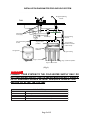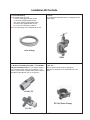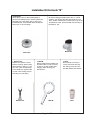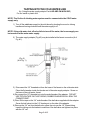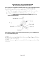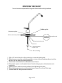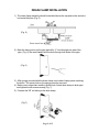
1
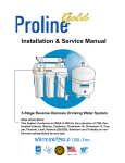
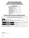
Plus
R
Installation & Service Manual
Plus
5-Stage Reverse Osmosis Drinking Water System
Plus
PROLINE GOLD
R
R
Congratulations on choosing the PROLINE® 5-Stage
Reverse Osmosis (RO) Drinking Water System
This high quality unit has been designed to fit under most kitchen
and wet-bar sinks. We suggest that you carefully review the
following information booklet before you attempt to install the
reverse osmosis system.
If you decide to install the unit yourself, please follow these
installation instructions, which have been simplified with color coded
tubing. All your local plumbing codes and regulations must be
followed while installing your RO system. For installation assistance,
contact your local dealer.
You will need to have a variable speed drill and 1/4’’ drill bit.
Depending on the texture of your sink (stainless steel or porcelain),
you will also need to use a compatible 1/2” hole saw (designed to
drill through stainless steel surface or porcelain surface). Extreme
caution needs to be exercised when drilling a hole through sink
surface. It is recommended that you use an existing hole if possible.
1/2’’ and 5/8’’ opened wrenches will also be required, as well as a
Phillips head screwdriver and a sharp tubing cutter. If drilling
through granite, a special granite drill bit is needed.
Your local dealer
Page 1 of 15
INSTALLATION DIAGRAM FOR PROLINE GOLD SYSTEM
Air gap dispensing
Faucet
Sink
A
B
Cold water
feed supply
Drain clamp
3/8” yellow tubing
to tank
Stage 5: carbon
postfilter
3/8” blue tubing
to faucet
1/4” red tubing
from flow restrictor
to drain clamp
Stage 4: TFC
membrane
Storage tanks
1/4” green tubing
Stage 3: carbon block
Stage 1: sediment prefilter
Stage 2: carbon block
(Fig. 1)
WARNING:
CONNECT YOUR SYSTEM TO THE COLD WATER SUPPLY ONLY. DO
NOT USE WATER SUPPLY THAT IS MICRO-BIOLOGICALLY UNSAFE,
OR OF UNKNOWN SOURCE WITHOUT ADEQUATE DISINFECTION
BEFORE OR AFTER THE SYSTEM.
Color Coded Tubing
Tubing
Directions
1/4" Green
Feed water supply line to inlet on sediment filter feed ball valve labeled “TO FEED”
3/8" Blue
3/8" Yellow
Carbon post filter elbow labeled “TO FAUCET” to center threaded shank of faucet
Carbon post filter tee labeled “TO TANK” to ball valve on storage tank
1/4" Red
Flow restrictor labeled “TO DRAIN” to waste water drain clamp
Page 2 of 15
Installation Kit Contents
1. Color Coded Tubing:
Color Coded Tubing (4 coils)
¼’’Green Tubing (approximately 8 feet)
¼’’ Red Tubing (approximately 6 feet)
3/8’’ Yellow Tubing (approximately 6 feet)
3/8’’ Blue Tubing (approximately 6 feet)
Note: The color coded tubing matches
the color coded plugs on the PROLINE ® RO unit.
2. SV-01:
SV-01 (Self Piercing Saddle Valve) for tapping into cold
water supply.
color tubing
SV-01
3. BV-2BC (Chromed Ball Valve NPT ¼’’) and AD-4BC3W (Chromed Adapter NPT ½’’) are used for tapping
into cold water supply at the top of undersink . If you
have a vinyl feed line or flexible metal feed line use the
BV-2BC and AD-4BC-3W. (see “A” of figure #1)
4. DC-14J:
DC-14J (Drain Clamp) used for tapping into
drainline for discharge of the wastewater down the
drain.
AD-4BC-3W
DC-14J (Drain Clamp)
BV-2BC
Page 3 of 15
Installation Kit Contents “B”
5.Teflon Tape:
Teflon Tape is used on all threaded fittings to
prevent water leakage. Eight rotations (layers) are
adequate when using Teflon tape to secure any
threaded fittings. The PROLINE ® RO already has
Teflon tape on all of its fittings.
6. BV-103-EZ:
BV-103-EZ (Storage Tank Ball Valve 3/8’’). In normal
operation, the Storage Tank Ball Valve must be in the
“open” position. Add 8 layers of Teflon tape on top of the
Threaded tank outlet. Screw tank ball valve securely on
threaded1/4” port.
BV-103-EZ
Teflon Tape
7. Release Tool:
Release Tool (Quick Connect
Release Wrench) allows easier
disconnecting of tubing ¼’’ and
3/8’’ from quick connect fittings.
Push release tool against collet
of quick connect fitting and pull
the tubing out of the fitting.
Release Tool
8. WR-1W :
WR-1W (White Wrench) Make sure
the black rubber O-ring is properly
in place in the filter housing after
changing filters following any
maintenance.
WR-1W
Page 4 of 15
9. 6FC6:
6FC6 (Faucet connector) to
connect the faucet with blue
3/8’’ tubing coming from the
post filter labeled TO FAUCET.
6FC6
TAPPING INTO THE COLD WATER LINE
A - (Using the water supply adaptor Part # AD-4BC-3W & BV-2BC)
For flex metal or plastic line.
NOTE: The Proline ® drinking water system must be connected to the COLD water
supply only.
1) Turn off the cold water supply to the sink faucet by locating the round or oblong
handle and turning clockwise until the water supply is off.
NOTE: If the cold water shut off valve fails to turn off the water, the house supply can
be turned off at the main water supply.
2) The water supply adapter (Fig. #2) may be installed at the faucet connection (A of
Fig. #1).
(Fig. 2)
(A of Fig. 1)
3) Disconnect the 1/2” threaded nut from the base of the faucet on the cold water side.
Place the flat washer inside the female end of the water supply adapter. Screw on
the base of the cold water faucet.
4) Re-connect the 1/2” threaded nut onto the male threads of the adapter. “DO NOT
USE TEFLON TAPE ON THIS THREAD, RUBBER WASHERS WILL SEAL THE
CONNECTIONS”.
5) Place Teflon tape on the 1/4” male threads of the ball valve supplied with the adapter.
Screw the ball valve into the 1/4” female port on the side of the adapter.
6) Remove the 1/4” nut from the ball valve, place the nut over the 1/4” Green tubing,
insert the tubing onto the barbed connection of the ball valve and tighten into place
with the 1/4” nut.
Page 5 of 15
TAPPING INTO THE COLD WATER LINE
B - (Using self-piercing saddle valve Part # SV-01)
NOTE: This valve is designed for standard copper lines. If your cold water line is not
plumbed with copper line, use water supply adapter AD-4BC-3W & BV-2BC.
1) Turn off cold water supply under the sink and install the saddle valve to the cold line.
Clamp onto a straight piece and tighten valve bolt.
2) Turn the valve handle clockwise so that it pierces the copper cold water line.
3) Install the ¼’’ green tubing from the first stage filter to the saddle valve (Fig. #3).
*Do not over tighten brass nut
(Fig. 3)
NOTE: All local plumbing codes must be followed to ensure proper installation and
use of your PROLINE ® system.
NOTE: Use brass insert and plastic ferrule when connecting tubing to saddle valve.
Cold Water Supply Valve (Figure #3)
CAUTION: A pressure regulator is recommended for feedwater pressure above 80 psi.
Page 6 of 15
DRILLING THE HOLE FOR THE FAUCET
NOTE: SAFETY GLASSES SHOULD BE WORN TO PROTECT YOUR EYES WHILE
DRILLING THE FAUCET WHOLE.
1) For best results, a 1/2’’ carbide-tipped drill bit should be used to drill a hole into your
sink for the auxiliary faucet.
2) Carefully select the faucet location making sure it will have a neat water fall pattern
and that the faucet stud will be accessible from below once the whole is completed.
3) For Porcelain Sink: Before starting the drill motor, apply firm downward pressure
on the bit until a crunching occurs. This will help keep the drill from moving when
starting the hole. Use a special porcelain hole cutter.
4) For Stainless Steel Sink: Before using 1/2’’carbide drill bit, an indent should be
made with a center punch to keep the drill bit from moving. A small pilot hole will also
aid the 1/2’’ drill bit.
5) For best results, keep steady firm pressure while drilling the hole. Too little pressure
during the start will cause excess wear on the bit and progress will be slow.
6) Once the hole is complete, clean the area of metal chips and roughness around the
hole. Metal chips will stain porcelain.
For granite use a special granite bit only, help cool bit with water.
Page 7 of 15
MOUNTING THE FAUCET
Your unit comes complete with a long reach faucet and mounting hardware.
Rubber gasket
Chrome cover plate
Sink or counter top material
Big metal washer
Metal toothed washer
Faucet nut
Faucet connector
3/8” X 7/16”
Blue 3/8” tubing
1) Drill a 1/2’’ hole in the sink or the counter top, or use and existing hole.
2) Slide chrome cover plate and rubber gasket on to stem of faucet and place faucet onto the
the sink, with the stem going through the hole.
3) Place metal slotted washer over threaded stem of faucet.
4) Place plastic spacer over threaded stem of faucet locking in place, slotted washer onto
countertop.
5) Tighten nut from under the counter surface to lock the faucet into place.
6) Thread the faucet connector onto threaded stem of faucet. Do not use Teflon tape.
7) Connect blue 3/8” tubing to faucet connector.
Page 8 of 15
DRAIN CLAMP INSTALLATION
1) The drain clamp assembly should be installed above the trap and on the vertical or
horizontal tail piece (Fig. 5)
(Fig. 5)
2) Mark the hole position on the pipe and drill a ¼’’ hole through one side of the
pipe. (Fig. 6). Be careful not to drill the hole through both sides of the pipe.
(Fig. 6)
3) Affix sponge provided with the drain clamp onto inside of clamp piece matching
the holes. The center hole on the sponge must be removed.
4) Make sure to align drain saddle to drilled hole. Attach drain clamp to drain pipe
and tighten the two screws evenly (Fig. 7)
5) Connect the 3/8’’ red tubing to the drain clamp.
(Fig.7)
Page 9 of 15
POSITIONING THE SYSTEM
1) The head assembly will stand up in the sink cabinet or can be hung on screws.
2) The storage tank may be laid on its side. The bladder tank will function on both ways
horizontal and vertical.
3) The head assembly and/or storage tank may be placed up to 10 feet from the point
of use with nominal pressure loss.
CONNECTING THE SYSTEM
Compression fitting may be found on the water supply adapter. To make the connections, slide
a compressor nut onto the tubing (Fig. 8). Slip the white plastic sleeve onto the tubing with the
beveled end towards the end of the tubing. Insert a brass insert into the tubing, bottom the
tubing into the fitting, slide the nut up and tighten with a wrench. DO NOT OVER TIGHTEN.
Connector
White Plastic Sleeve
(Fig. 8)
Brass Insert
Compression nut
Plastic Tubing
NOTE: Do not use the brass sleeves on plastic tubing, use only plastic sleeves on
plastic tubing.
2) The plastic fitting on the drain clamp is connected by slipping the plastic nut onto the
tubing. Bottom the tubing into the drain clamp and tighten firmly without tools.
3) Use the color coded tubing to make the following connection.
Color Coded Tubing
Tubing
Directions
1/4" Green
Feed water supply line to inlet on sediment filter feed ball valve labeled “TO FEED”
3/8" Blue
3/8" Yellow
Carbon post filter elbow labeled “TO FAUCET” to center threaded shank of faucet
Carbon post filter tee labeled “TO TANK” to ball valve on storage tank
1/4" Red
Flow restrictor labeled “TO DRAIN” to waste water drain clamp
Page 10 of 15
EZ FITTINGS- QUICK CONNECT
Your PROLINE ® reverse osmosis system is equipped with EZ fittings. The quick connect
fittings feature leak proof installations. EZ Fittings provide efficient quick connection and
disconnection resulting in reduction of service time and labor cost.
1 Cut tube into square
Cut the tube square. It is essential that the outside diameter be free of score marks
and that burrs and sharp edges be removed before inserting into fittings. For soft
thin walled plastic tubing, we recommend the use of a tube insert.
2 Insert tube
Fitting grips before it seals. Ensure tube is pushed into the tube stop.
3 Push up to tube stop
Push the tube into the tube stop. The collet (gripper) has stainless steel
teeth which hold the tube firmly in position while the ‘O’ ring provides a
permanent leak proof seal.
4 Pull to check secure
Pull on the tube to check that it is secure. It is a good practice to test the
system prior to leaving site and/or before use.
Disconnecting
Push in collet and remove tube
To disconnect, ensure the system is depressurized before removing the tube.
Push in collet squarely against face of fitting. With the collet held in the
position, the tube can be removed. The fitting can there be re-used.
Page 11 of 15
START UP PROCEDURE
1) Check to see all connections are made
2) Check that the pre-filter and pre-carbon sumps are secure with “O” rings in place using
the housing wrench provided.
3) Slowly turn on the water by turning the needle valve counterclockwise or ball valve 1/4
turn,where handle is parallel to the tubing line.
4) The valve handle on top of the tank should be in the open position, parallel to the valve
body.
5) The handle of the faucet should be in the closed position.
6) Check for leaks.
7) The PROLINE ® drinking water system makes 2 gallons of drinking water per hour and
requires 2 hours before water is readily available.
8) During this initial fill period, you will hear water being discharged through the red drain
line. This is normal as the contaminated water is being rejected by the reverse osmosis
membrane.
WARNING: DO NOT DRINK WATER FROM THE FIRST TANK PRODUCED BY THE
SYSTEM. DISCHARGE THE WATER FROM THE STORAGE TANK BY OPENING THE
FAUCET. DISCHARING MIGHT TAKE UP TO 15 MIN.
If you have any difficulties with the installation, or require additional information on your unit
please consult your local dealer.
We thank you for purchasing our PROLINE ® Reverse Osmosis drinking water unit. In
order to maintain high quality pure water, it is important that scheduled maintenance
be followed.
RECOMMENDED MAINTENANCE
1) Sediment Pre-filter: The Pre-Filter protects the system and should be maintained
regularly. The snow-white Pre-Filter should be changed when the outside discolors to a
cardboard brown color and before the inner core discolors. The life of the Pre-Filter will
depend upon condition of your water supply and should be checked at 3 month
intervals until a filter life is established (average life 6 months). Always make sure
that o-rings are seated properly inside sumps before tightening canisters.
2) Carbon Blocks: Designed to remove chlorine from the water supply, as well as organic
and inorganic substance before entering the TFC membrane (average life 12 months).
Always make sure that o-rings are seated properly inside sumps before tightening
canisters.
3) Post-Carbon: The post-filter should be changed when you experience an unusual taste
and/or odor to the water and has a nominal life of 1 year.
4) Membrane: The high quality Thin Film Composite membrane should last between 2 to
5 years depending on the quality of your local water.
.
Page 12 of 15
5) Drain your storage tank twice each month to ensure the freshness of the water in the
storage tank by lifting the faucet handle into the open position until water flow stops from
the tank. Return the faucet handle to the closed position and the tank will refill in 2 hours.
It is best to drain the system before retiring for the evening
6) Manual Flushing: Flushing your system twice per month (for 5 minutes each time) will
enhance the performance and prolong the life of the TFC membrane.
NOTE: MINIMUM PRESSURE REQUIRED TO OPERATE YOUR PROLINE ® SYSTEM
IS 40 PSI. A BOOSTER PUMP ASSEMBLY IS REQUIRED WHEN FEED PRESSURE
DROPS BELOW 40 PSI.
IMPORTANT NOTES-MUST READ:
1) Your PROLINE ® system has been thoroughly tested and inspected for
production, leaks, and shut-off functions at our factory. Therefore, it might
have some water in it.
2) Do not use this system on feed water that has biological contamination or if
feed water is of unknown source.
3) All local plumbing codes must be followed to ensure proper installation and
use of your PROLINE ® RO System.
4) Flush your RO system (using manual flushing valve located on the unit
assembly) twice every month. Flushing the system for 5 minutes at a time
will enhance the quality and prolong the life of the TFC membrane.
5) Should you require additional information or need further technical
assistance on PROLINE ® system, contact your local dealer.
Page 13 of 15
HOW TO MANUALLY FLUSH THE MEMBRANE
The Manual Flushing Device is located in between the Membrane Housing and the Post
Carbon on top of the Proline RO unit, containing the Flow Restrictor (FR-450) and the straight
ball valve in between the two “Y” fittings.
REVERSE OSMOSIS FLUSHING DEVICE
Flushing Instructions:
1) Close tank valve
2) Open faucet handle
3) Rotate ball valve to FLUSH position for 5 minutes
4) Open tank ball valve and close faucet handle (normal settings)
5) Return flush ball valve to IN SERVICE position
CHANGING THE SEDIMENT, GAC, AND CARBON BLOCK FILTERS
CAUTION: ANY REPLACEMENT FILTERS OR MAMBRANES NOT RECOMMENDED
BY THE FACTORY CAN CAUSE SEVERE DAMAGE TO THE SYSTEM AND VOID ALL
WARRANTIES.
1) Shut off the feed water to the system by turning the saddle valve on the water supply
adapter clockwise until it stops or ball valve 1/4 turn,where handle is perpedicular to
the tubing line.
2) Close the storage tank ball valve by turning the handle perpendicular to the valve
body.
3) Press down on faucet handle to relieve pressure.
4) Allow 3-5 minutes for pressure in system to drop.
5) Remove the filter sumps with the housing wrench by turning the sump to the left
(counterclockwise). If the “O”-ring in the sump is stretched or worn, it should be
replaced to maintain a proper seal.
6) Remove the old filter and gaskets (if any) and insert the new filter.
7) Check the pre-filter, if it has a heavy dirt load it can restrict water flow to the system,
Change sediment pre-filter regularly.
8) If the storage tank is heavy with water and will not empty it has lost its air charge and
need to be serviced or replaced. The air charge in the tank should be 5-7 psi with
the tank empty of all water.
9) Always make sure that “O”-rings are seated properly inside sumps before
tightening canasters.
Page 14 of 15
PROLINE ® LIMITED WARRANTY
The PROLINE ® reverse osmosis system is warranted to be free from defects in materials and workmanship under normal use within the operating parameters listed below. For a period of twelve months from the
date of purchase PROLINE ® will repair or replace any part of the reverse osmosis system with the
exception of the filters and electrical components.
CONDITIONS OF WARRANTY:
The above warranty does not apply to any part of the PROLINE ® reverse osmosis system that is damaged because of neglect, misuse, alteration, misapplication, physical damage, fouling and/or scaling of the
membrane by minerals, bacterial attack, sediment or damage cause by fire, freezing, hot water, or an act of
God.
PROLINE ® assumes no warranty liability in connection with this reverse osmosis system other then
specified herein. PROLINE ® shall not be liable for consequential damages of any kind or nature due to the
use of PROLINE ® products.
WARRANTY SERVICE:
PROLINE ® will provide warranty service under the following conditions:
1)
Contact your local dealer who will obtain return authorization instructions.
2)
Ship the unit or part freight prepaid for warranty evaluation or service with RMA # written on
package. Systems or parts covered under the warranty shall be repaired (or, at our option replaced) and
returned without charge.
CONDITIONS FOR OPERATION:
Source Water Supply-TFC:
Community/Private
System Pressure
Temperature
PH Range
Maximum feed TDS level
Maximum Turbidity
Non-Chlorinated
40-100psi
4-38 C (39-100 F)
3.0 to 11.0
2000 ppm
1.0 Net Turbidity (NTU)
Chemical Parameters-TFC:
Maximum Hardness
350mg/L (20 gpg)
Maximum Iron (Fe)
0.1 mg/L
Maximum Manganese (Mn)
0.05 mg/L
Maximum Hydrogen Sulfide (H2S) 0.00 mg/L
Maximum Chlorine (C12)
2.00 mg/L
A pressure regulator is recommended for feedwater pressure above 80 psi.
Although TFC membranes are designed for non chlorinated feed supply, your PROLINE ® RO system is
equipped with double carbon pre-filtration for Chlorine removal prior to the TFC membrane.
Page 15 of 15
Plus
R
Distributed by:
Serial #