1
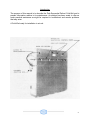
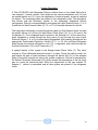
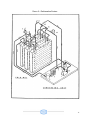
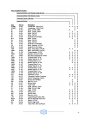
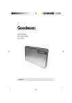
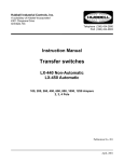
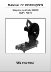
DOLE REFRIGERATING COMPANY
1420 Higgs Road • Lewisburg, Tennessee 37091
Phone (931) 359-6211 1-800-251-8990
www.doleref.com
SEQUENTIAL DEFROST
SERVICE MANUAL
June 2002
1
SEQUENTIAL DEFROST
Table of Contents
Introduction
4
COLD-WEL Auto-Sequential Holdover Blower System
5
COLD-WEL Sequential Defrost System Configurations
7
Refrigeration System Description
10
Refrigeration System Equipment Items
12
Sequential Defrost Operation
Sequential Defrost With Heat Operation
Sequential Defrost With Manual Initiate Operation
Sequential Defrost With Manual Initiate & Heat Operation
Operation of Defrost Cycle Termination
13
15
17
19
21
Control Settings
22
Troubleshooting
Blower Motor Fails to Run Over the Road
Blower Motor Will Not Operate on AC Power
Defrost Cycle Fails To Terminate
Battery Drained While operating on AC
Reduced Air Flow From Blower
Blower Motor Reverses Direction
Winter Heat Failure
Cycle Timer Will Not Advance
System Will Not Go Into Defrost
Ice Buildup on Plates
Ice Buildup on Compressor
23
23
23
24
25
26
26
27
27
28
28
29
Charging the System
Replacement Parts
Warranty
30
31
32
2
List of Illustrations
Figure 1 – Cold Wel System Variations
9
Figure 2 – Refrigeration System
11
Figure 3 – Sequential Defrost Electrical Schematic
14
Figure 4 – Sequential Defrost with Heat Electrical Schematic
16
Figure 5 – Sequential Defrost with Manual Initiate Electrical Schematic
18
Figure 6 – Sequential Defrost w/ Manual Initiate and Heat Electrical Schematic
20
3
Introduction
The purpose of this manual is to describe the Dole Sequential Defrost Cold-Wel and to
present information relative to its maintenance. An attempt has been made to offer as
much practical assistance as might be required to troubleshoot and resolve problems
that may arise.
A Cold-Wel ready for installation in a truck.
4
Cold-Wel Auto Sequential Holdover Blower System
Features of Cold -Wel Sequential Defrost Holdover Blower Systems:
1. The special dual circuit zero degree F. holdover plates provide twice the
plate-surface-to-body air temperature difference as plus 18 degrees F. plates in
other holdover blower systems. This feature results in Cold-Wels having the
capacity to cool an enclosure at twice the rate of other systems.
Cold-Wel units can contain three or four plates, each plate having two
independent coils. One coil is used for cooling and freezing the eutectic solution
while the other is used for defrosting the eutectic solution by means of circulating
hot gas.
2. The top air intake and discharge openings result in a cold "trap" within the
Cold-Wel. This trap prevents cold heavy air from flowing out of the unit when the
blower fan is off. This feature eliminates product freezing and the "waste" of
holdover cooling when truck doors are open, and/or the truck thermostat is not
calling for cooling. Since the Cold-Wel frame is insulated, product can be stored
up next to the unit without fear of freezing.
3. Dual blowers on a double-shafted motor provide a high velocity blast of air
along the ceiling to the rear of the body for full product protection. The blower
motor is powered from the truck battery while on the delivery route and by
external power when the condensing unit is plugged into external power at
dockside for the purpose of refreezing eutectic in the plates.
4. The air inlets are located near the top of the unit to receive the warmest air in
the body. This is especially important after a door opening has resulted in an
inrush of air from outside with its accompanying higher temperature.
5. The closed bottom of the unit permits product to be stacked against the
exterior of the Cold-Wel, a feature that permits full use of available floor space.
This feature also prevents water, which flows off of the plates during defrosting,
from flooding the truck body floor.
The rapid reduction of body temperature after door openings, inherent in the
Cold-Wel design, results in reduced total blower motor heat load, and a reduction
in the total load on the truck battery.
6. During the plug-in period, hot gas is directed to the hot gas coil in the
preselected eutectic plate. This hot gas circulates through the coil and melts the
eutectic in the plate. The warmed solution melts the plate's surface frost. The
defrost cycle may be initiated automatically or manually, depending upon the
configuration of the Sequential Defrost system employed. The defrost cycle is
terminated when a temperature sensor in the hot gas return line indicates the
plate's eutectic solution has been sufficiently heated to eliminate surface frost
(approx. 70 degrees).
5
7. A winter heat option is available in all Cold-Wels. This option can prevent
product freezing when the unit is plugged into external power at dockside in
Northern climes where heating may be required due to extremely low outside
temperatures.
6
Cold-Wel Sequential Defrost System Configurations
Cold-Wel sequential defrost is offered in fo ur different configurations:
-Sequential Defrost
-Sequential Defrost with Heat
-Sequential Defrost with Manual Initiate
-Sequential Defrost with Manual Initiate & Heat
Figure 1 illustrates the differences between the different configurations.
Sequential Defrost
In this configuration, plugging in external 230VAC power will automatically initiate
defrost of a selected plate. At the instant the external power is applied to the unit, the
Cycle Timer in the unit's Control Panel selects a plate for defrost. Refrigerant and hot
gas solenoid valves are opened and/or closed to permit hot gas to circulate through the
selected plate and to allow refrigerant to flow through the other plates.
The defrost cycle will be terminated when a temperature sensor indicates that the hot
gas exiting the plate undergoing defrost has reached 70 degrees F. At that time the
defrosted plate will be placed in the refrigerate mode and refrigerant will flow through its
coil.
Should external power be interrupted for any reason, i.e. power failure or intentional
disconnect as a result of moving the truck, the defrost cycle for the selected plate will be
terminated. Subsequently, when external power is restored, the Cycle Timer will select
the next plate due for defrost and will position the refrigerant and hot gas valves in such
a manner that this plate will be in the defrost mode and the remaining plates will
undergo refrigeration.
Sequential Defrost with Winter Heat
In this configuration, a manually operated selector switch is included which can place
the unit in the Refrigerate or in the Heat mode. In the Refrigerate mode, the system
operates in the same manner as the Sequential Defrost just described. When placed in
the Heat mode, a heater in the Cold-Wel energized and air flows over the heater when
the truck thermostat calls for heat. While in the Heat mode, the Condensing Unit is
electrically locked out. Heat is available only at dockside since the heaters are 240VAC
elements.
7
Sequential Defrost with Manual Initiate
When external power is connected to the truck, depressing the momentary contact
Manual Initiate Switch on the external Control Box will cause the Cycle Timer to select a
plate for defrost and place the remaining plates in the refrigerate mode. This operational
mode will be maintained until the defrost cycle is completed, at which time the defrosted
plate will be refrigerated, as was the case in systems without the Manual Initiate feature.
Should the power be interrupted for any reason, a resumption of power will permit the
system to continue operating in the same mode as before power was interrupted. This
is accomplished by a latching relay in the external Control Box. In other words, if power
was interrupted with a specific plate in the defrost mode, subseque nt restoration of
power will permit the continuation of defrost of that plate. For any plates in the
refrigerate mode at power interruption, restoration of power will allow the refrigeration of
those plates to continue.
Sequential Defrost with Manual Initiate & Heat
A system in this configuration operates in the same manner as the one just described
except, as was the case with Sequential Defrost, placing the Refrigerate/Heat Switch in
the Heat position prevents the Condensing Unit from operating and places the unit's
blower under the control of the truck's thermostat. Whereas this thermostat will call for
cooling with rising temperature when the system is in the Refrigerate mode, it will call
for heating with falling temperature when in the Heat mode. Heat is available only at
dockside since the heaters require 240 VAC.
8
Figure 1 – System Variations
9
System Description
A Dole COLD-WEL with Sequential Defrost contains three or four plates filled with a
zero degree F. eutectic solution. Each plate has an internal refrigeration coil (13) and
an internal defrost coil (21). Upon the application of external power, a plate is selected
for defrost. The remaining plates are placed in the refrigerate mode. The description
that follows and the illustration, pertain to the three-plate Sequential Defrost
configuration. Defrost is accomplished by energizing the Liquid Solenoid Valve (7, 8, or
9) and the Hot Gas Solenoid Valve (15, 16, or 17) on the plate selected for defrost.
The compressor discharge is routed through the open Hot Gas Solenoid Valve, through
the plate's defrost coil, out the Hot Gas Return Check Valve (18, 19, or 20), and to the
Condenser (4). The condensed liquid is stored in the Receiver (5). At the same time,
liquid refrigerant is routed through the King Valve (6) and through the open Liquid
Solenoid Valves (7, 8, or 9) on plates being refrigerated. After passing through the two
appropriate Thermostatic Expansion Valves (10, 11, or 12), the cold liquid refrigerant
flows through the internal refrigeration coils (13), is vaporized, and routed through the
Suction Accumulator (14) to the Compressor (1).
A special feature of this system is the Spring-loaded Check Valve (3). This valve
requires a 30 psi differential pressure across it to open. During the defrost mode, hot
gas follows the path of least resistance (through the defrost coil (21) of the selected
plate). During this time the coil acts as the system condenser. Defrost is terminated by
the Defrost Terminate Thermostat (22), which senses the temperature of the hot return
gas as it exits the defrosted plate. When the temperature of this gas reaches 70
degrees F., defrost is terminated and all three plates are placed in the refrigerate
mode.
10
Figure 2 – Refrigeration System
11
Refrigeration Equipment Items (Refer to Figure 2)
Ref. No.
Nomenclature
1. Compressor
2. Discharge Service Valve
3. Spring-loaded Check Valve
4. Condenser
5. Receiver
6. Liquid Line King Valve
7. Liquid Solenoid Valve No. I (NO)
B. Liquid Solenoid Valve No. 2 (NO)
9. Liquid Solenoid Valve No. 3 (NO)
10. Thermostatic Expansion Valve No. 1
11. Thermostatic Expansion Valve No. 2
12. Thermostatic Expansion Valve No. 3
13. Internal Plate Refrigerant Coil
14. Suction Accumulator
15. Hot Gas Solenoid Valve No. 1 (NC)
16. Hot Gas Solenoid Valve No. 2 (NC)
17. Hot Gas Solenoid Valve No. 3 (NC)
18. Hot Gas Return Check Valve No. 1
19. Hot Gas Return Check Valve No. 2
20. Hot Gas Return Check Valve No. 3
21. Internal Plate Defrost Coil
22. Defrost Terminate Thermostat
23. Suction Service Valve
Part No.
28-123
28-123
28-123
28-120
28-120
28-120
28-211
28-211
28-211
Not spared
06-073
Cold Wel Condensing Unit System shown in Figure 2 is a three-plate unit. In a
four-plate unit an additional liquid sole noid valve, hot gas solenoid valve, thermostatic
expansion valve, and hot gas return check valve would be included.
Part supplied by others
Sporlan TEVs--28-429 (R502) and 28-431 (R22)
Alco TEVs--28-423 (R502) and 28-427 (R22)
12
Sequential Defrost Operatiion
(Refer to Figure 3)
There are two basic circuits in a Sequential Defrost System:
1. The "ready loop". It must be closed to permit blower operation. The ready loop
includes a Dash Switch (D/S) on the truck dash, a Truck Thermostat (TCI), two
Door Switches (D/R), and a DC Relay (R1).
2. The "cycle timer loop". It determines which plate is to be defrosted and which
plates are to be refrigerated. The loop includes a Cycle Timer (M2), 2 cams per
plate, a Time Delay Relay (TDR), and a Defrost Terminate Relay (R3).
When all items in the ready loop are in the closed position the blower operates on direct
current (DC) power. This power is supplied by the truck battery or by external power
when the truck is at dockside. When external power (AC) *is connected to the truck,
Relay (R2) will be energized and DC power will be available to the Blower motor (MI)
from the Rectifier (FWB1) and not the Battery (+ & -). This is true whether or not the
Dash Switch (D/S) is closed.
The Cycle Timer Motor (M2) in the cycle timer loop can have 6 or 8 cams. The 6-cam
configuration (for 3-plate units) is shown here. An 8-cam Cycle Timer is required for a
4- plate configuration. The instant that external power is connected to the truck, the
Time Delay Relay (TDR) is energized and voltage is available to the Cycle Timer Motor
(M2) through the normally closed contact of the TDR. After approximately one second
this contact opens. The timer cams will rotate for a third of a revolution (120 degrees),
at which point one of the cams (2, 4, or 6) will open, breaking the circuit to the timer.
Then one of the timer's cams (1, 3, or 5) will be closed; the other two will be open.
Since the Liquid Solenoid Valves (LSVI, 2, and 3) are normally open valves and the Hot
Gas Solenoid Valves (HSV1, 2, and 3) are normally closed valves, the cam that is
closed will dictate which plate is to be defrosted and which plates refrigerated.
Defrost continues until TC2 senses that the return hot gas exiting from the plate being
defrosted has reached 70 degrees F. 'At that time TC2 will close and R3 will be
energized. The normally closed contact of R3 opens; all plates are placed in the
refrigerate mode. R3 remains energized until external power is removed.
The system remains in the refrigerate mode as long as external power remains
connected. Should power be interrupted for any reason, its reapplication will cause the
next plate in line to be placed in defrost and the complete cycle will begin again.
13
Figure 3 – Sequential Defrost
14
Sequential Defrost with Heat Operation
(Refer to Figure 4)
The operation of this version of Sequential Defrost is identical to that of the system just
discussed when cooling is called for in the truck. However, there is an additional circuit,
the winter heat circuit, that affects the operation of the system.
The heat circuit includes a Refrigerate/Heat Switch(SW3), an On/Off Switch (SW2), a
Heater (HTR), a High Limit Switch (H/L), a Truck Thermostat (TC1), and a Heat Initiate
Relay (R3A). With the Refrigerate/Heat Switch in the Refrigerate position, the system
operates in the same manner as the one just discussed.
The heater is actuated when the Refrigerate/Heat Switch is placed in the Heat position.
Since the Heater operates only off of AC power, this circuit is only effective when the
truck is connected to external power at dockside. As long as R3A is energized, the
Compressor Contactor (Cl) sees an open circuit, rendering the Compressor incapable of
operating. Whereas, the Truck Thermostat (TC1) calls for cooling on temperature rise
when in the refrigerate mode, it will call for heat with a decrease in temperature when in
the heat mode.
15
Figure 4 – Sequential Defrost with Heat
16
Sequential Defrost with Manual Initiate Operation
(Refer to Figure 5)
The operation of the "ready loop" in controlling the blower is identical in all versions of
Sequential Defrost. The operation of the Cycle Timer is also identical in all versions.
However, the "initiation of defrost" and the "termination of defrost" are somewhat
different.
A Manual Initiate Control Box is an added feature of this configuration. The box contains
a Latching Relay (LR), an Enabling Relay (R5), a Control Transformer (XFMR2), and a
Defrost Initiate Switch (SW1).
As was the case in systems without Manual Initiate, the Defrost Terminate Thermostat
(TC2) terminates defrost by sensing the temperature of the hot gas exiting the plate
being defrosted.
The important difference between this system and versions without the Manual Initiate
feature is as follows:
1. In all Sequential Defrost configurations the removal of external power stops
defrost and refrigerate functions.
2. In configurations without Manual Initiate the application of power will cause the
Cycle Timer to rotate 120 degrees, placing a new plate in the defrost mode and
placing the other plates in the refrigerate mode.
3. In systems with the Manual Initiate feature, application of external power will
cause the system to continue operating in the same mode in which it had been
operating when external power was last interrupted. In other words, if a plate was
in the defrost mode and the other plates were being refrigerated at power
interruption, the reapplication of power would simply permit them to continue in
those modes.
4. In systems with the Manual Initiate feature, it is necessary to depress the
momentary contact Defrost Initiate Switch (SW1) to cause the Cycle Timer to
place a new plate in the defrost mode.
In summary, the Manual Initiate feature prevents the system from arbitrarily removing a
plate from the defrost mode before it had been completely defrosted as a result of a
power failure or disconnecting and reconnecting external power. It permits the moving
of a truck during a plug-in period without jeopardizing the effectiveness of the defrost
and refrigerate functions. It is important to remember that the Manual Initiate Switch
must be activated once when the truck is first connected to external power for its
pulldown to assure that the next pla te due for defrost will be selected. If this is not done
the plate last defrosted will be defrosted again.
17
Figure 5 – Sequential Defrost with Manual Initiate
18
Sequential Defrost with Manual Initiate and Heat Operation
(Refer to Figure 6)
The method of controlling defrost, refrigeration, and blower operations is the same as
the system with Manual Initiate. The method of controlling heat is the same as for the
Sequential Defrost with Heat option.
19
Figure 6 – Sequential Defrost with Manual Iniate and Heat
20
Operation of Defrost Cycle Termination
In all Sequential Defrost configurations the defrost cycle is terminated automatically.
Since hot gas defrost is accomplished by transferring heat from the gas circulating
through a plate to the eutectic solution in the plate, the amount of heat transferred will
be reduced as the eutectic solution is melted. As a result, the hot gas exiting the plate
will be warmer due to the fact that it transfers less heat to the eutectic as the eutectic
temperature rises above its freezing point. A thermostat, installed in the hot gas return
line and set to close at 70 degrees F., acts to terminate the defrost cycle. At this time
the defrosted plate is placed in the refrigerate mode.
Note: Each time the external AC power source is interrupted, regardless of the reason,
the defrost and refrigerate cycles are terminated. Upon the resumption of power, both
cycles will begin again. However, in units which do not have a Manual Defrost Initiate
System, a new plate will be selected for defrost. In units with Manual Defrost Initiate, if a
plate was in the defrost mode when power was interrupted, it will continue in that mode
when power is reapplied until defrost is complete. If the plate was in the refrigerate
mode at the time of power interruption, it will remain in that mode when power is
reapplied until the cycle is complete.
Defrost time should not exceed four hours. On warm days, when most of the eutectic
solution in a plate has been melted, the defrost cycle will be shorter due to the small
amount of eutectic to be melted. On cold days, when little solution has been melted,
defrost will take more time due to the greater amount of heat that must be transferred to
the greater amount of eutectic.
21
Control Settings
(Refer to Figure 2)
The Hot Gas Defrost coil (21), located within a plate, functions as the condenser during
that plate's defrost cycle. Therefore, it is critical that head pressure be properly
controlled during the defrost cycle. A high head pressure equates with hotter gas for
defrost, while a low head pressure and its resulting lower temperature gas would tend to
increase the time required to defrost a plate.
A spring-loaded Check valve (3) prevents the Compressor discharge from going directly
to the Condenser (4) until it has passed through the Hot Gas coil (21). This valve is set
to open when the pressure differential across it rises above 20 psig.
A Defrost Terminate Thermostat (22) monitors the exit temperature of the hot gas to
assure that defrost is complete. The Thermostat is set to terminate defrost when the
exiting hot gas temperature reaches 70 degrees F.
A Condenser Fan Control Switch controls variations in head pressure and is 'set to cut
in at 265 psig and cut out at 220 psig.
A Suction Pressure Control Switch is set to cut out at 6 psig and cut in at 16"psig
A Crankcase Pressure Regulator may be used to limit the load on the compressor. If
used, this regulator should be set to close at the maximum running load (amperes) of
the condensing unit during the initial pulldown of the refrigeration system.
22
Troubleshooting
Refer to the applicable electrical schematic for the discussion that follows.
(Figure 3, 4, 5 or 6)
Troubleshooting (Blower motor fails to run over the road)
In transit, assuming truck doors are closed and the Truck Thermostat TC1 calls for
cooling, the Blower Motor (MI) should run off of truck battery power (B+ to B-). Failure of
the motor to run under these conditions can produce the following symptoms:
1. Warm product and truck body temperature.
2. No noticeable movement of air in the truck.
If such is the case, the following should be checked:'
1. The toggle switch (D/S) mounted on the truck dash should be in the "on"
position. Indicator light (P4) should be lit.
2. If M1 runs when contact arm of R1 is depressed, the probable cause of trouble
is the R1 coil circuit.
If the motor fails, to run when the R1 contact arm is depressed, check for the following:
1. Open Circuit Breaker (CB).
2. No voltage between B+ at M1 and Ground.
If M1 runs at reduced speed, check for the following:
1. Brushes making poor contact.
2. Worn brushes and/or low brush spring tension.
3. Check voltage across motor (M1). If low, find cause (loose connection, etc.).
Troubleshooting (Blower motor will not operate on AC power)
If MI operates on DC power, but not on AC, two circuits must be checked: 230 VAC and
12 volt rectified circuit.
1. All Door Switches (D/R) should be closed.
2. TC1 should be set low enough to call for cooling.
3. R1 should be energized.
4. 230 VAC should be available at the Ll and - L2 terminals of FWB2 Terminal
Strip in the Control Panel.
5. Press R1 contact arm down with an insulated object.
6. If M1 does not run, check CB. Replace if open.
7. If M1 runs, check R1 for 12VDC. If available across the coil, replace R1.
8. Check position of R2 contact arm. It should be in a downward position when
operating off of AC power.
9. Check Primary and Secondary voltage across XMFR1 (wires Ll and L2.,for
Primary and 22 and 23 for Secondary). Primary voltage should be nominally 230
volts and Secondary a minimum of 15VAC.
10. Check FWB1 output. If less than 12 volts, replace.
23
Troubleshooting (Defrost cycle fails to terminate)
The Defrost Termination Relay (R3) is equipped with a neon light that illuminates when
energized. To check the status of R3 proceed as follows:
1. Remove panel to gain access to the Control Panel.
2. Observe R3 relay. If light is lit, relay is energized and all plates should be in
the refrigerate mode.
3. If R3 is not energized (light off), either (TC2) has not yet sensed 70 degrees F.
in the hot gas return line from the plate under defrost, or the R3 relay is defective.
4. Check for voltage to R3. If voltage is present, check for continuity across the
R31s normally closed contact (wire Ll to 13). If there is continuity, R3 is defective
and should be replaced.
NOTE: When defrost terminates a change can be noticed in the sound of the
compressor. Shortly after defrost terminates, the discharge line from the Spring Loaded
Check Valve will become very hot to the touch.
5. Check for continuity across TC2 (wire Ll and 21). If TC2 is open, check
temperature of hot gas return line from the defrosted plate in the vicinity of the
TC21s sensing bulb. 'If temperature is 70 degrees F. or higher, check setting of
TC2. If TC2 cannot be adjusted to close at 70 degrees F., replace it.
6. Check operation of the Spring-loaded Check Valve. If this valve fails in the
open position, discharge gas is free to flow in two directions during defrost;
straight to the Condenser and through the defrost coil of the plate undergoing
defrost. If this situation exists, the greatly diminished supply of hot gas to the
plate will result in increased defrost time and possibly the inability to defrost at all.
If this valve fails in the open position, the discharge line on either side of it should
be equally hot to the touch.
7. To replace the Spring-loaded Check Valve, proceed as follows: (Refer to
Figure 2).
- Close the King Valve (6). Operate the system in the defrost mode on each
plate. Unplugging and reconnecting the external power will assure cycling the
system through each plate on systems without Manual Initiate. Simply
depressing the momentary contact Manual Initiate Switch will cycle another plate
to the defrost mode. This cycling should remove as much refrigerant as possible
from each-plate.
-Disconnect power from unit.
-Close Compressor Discharge and Suction Service Valves (2 and 23).
-Remove refrigerant from system.
-Unsolder valve from system and replace.
NOTE: Never work in the presence of liquid, refrigerant without wearing safety
goggles and protective clothing.
24
Troubleshooting (Defrost Cycle fails to terminate)
The system includes a Defrost Terminate Thermostat (TC2) which terminates defrost
when hot gas returning from a defrosted plate reaches a temperature of 70 degrees F.
Failure to terminate defrost can be caused by a thermostat set incorrectly, or one with a
broken sensing bulb.
A defective R3 Relay can also result in failure to terminate defrost. Should a defective
Defrost Terminate Thermostat be observed, it should be replaced as follows:
1. Disconnect power source.
2. Remove upper blower section cover.
3. Remove insulating tape from sensing bulb.
4. Remove clamps holding sensing bulb.
5. Remove cover from the thermostat and disconnect two wires. Remove
thermostat holddown screws. Remove thermostat.
6. Repeat above in reverse to install new thermostat.
NOTE: Insulating tape must be used to install the sensing bulb on the thermostat. Lack
of insulation can prevent the system from terminating defrost.
Troubleshooting (Defrost cycle fails to terminate)
Should dirt or other foreign material prevent a Hot Gas Solenoid Valve from closing
when defrost is completed, even though the defrost cycle is over electrically, the plate's
eutectic is still being warmed by hot gas flowing through its defrost coil. To replace such
a valve:
1. Remove external power.
2. Remove and replace valve. (See Charging the System).
Troubleshooting (Defrost fails to terminate)
If a unit does not sequence to the next plate af ter disconnecting and reconnecting
power, or in systems with Manual Initiate af ter depressing the Manual Initiate Switch
(SW-1), check Cycle Timer (M2) for rotation. If there is none, proceed as follows:
1. Disconnect power.
2. check for continuity through M2 leads. If no continuity, replace Cycle Timer
(M2). DO NOT TRY TO REPLACE MOTOR ONLY.
3. Disconnect wires' Ll and L2 from the TDR; check for continuity. If none,
replace the TDR.
If M2 runs continuously, disconnect wire Ll from TDR. If M2 stops, TDR is defective and
should be replaced. If M2 continues to run, programming of the Cycle Timer should be
checked. If resetting the cams properly does not resolve problem, replace the Timer.
Troubleshooting (Battery drained while operating on AC)
When external power is applied to the system, (R2) will be energized. This will open the
circuit from the Battery and close the circuit to the Rectifier (FWB1). If R2 is defective,
25
M1 will continue to operate off the battery power even though external power is
available. If allowed to continue, the truck battery could be completely drained.
To check the R2 Relay coil circuit, proceed as follows:
1. Check Secondary output of Transformer (XMFR1). If 15 VAC minimum is not
available across the two AC terminals of FWB1, check voltage across the
Transformer Primary. If, 230 VAC is not available, check main power source to
truck.
2. If 230 VAC is available across the coil of R2 and the coil is not energized,
replace R2.
3. If 230 VAC is not available across the coil of R2, check for 230 VAC to Ll and
L2 terminals on FWB2.
4. If 230 VAC is not available, locate the source of power failure.
Troubleshooting (Reduced air flow from blower)
Symptoms of reduced air flow can be warm body and product temperature and/or no
noticeable air movement in truck. It can result from the following:
1. Dirty commutator or worn brushes cause motor to run at reduced speed.
2. Defective Rectifier (FWB1).
3. Excessive ice buildup on plates due to improper defrosting. See
Troubleshooting (Defrost fails to terminate)
If reduced air flow is detected the following sho uld be checked:
1. Toggle Switch (D/S) on truck dash should be "on".
2. Depress contact arm of R1 Relay. If M1 begins to run, fault is in the RI Relay
circuit.
3. If M1 does not run, check CB for open circuit.
4. Check voltage across M1; should be 12VAC minimum. If lower, check for
loose connections.
5. If M1 continues to operate at reduced speed, check for brush wear and
reduced spring tension.
6. Check fan for proper rotation. Blades should be moving downward as viewed
from in front of the-unit. See Troubleshooting (Blower motor reverses direction)".
Troubleshooting (Blower Motor reverses direction)
If the Blower Motor (Ml) runs in one direction when on Battery Power (DC) and in the
opposite direction when on External Power (AC), check for the following :
1. Determine correct fan rotation (fan rotation on DC or on AC power). The air
should be expelled from the two vertical rectangular outlets in the front of the
Cold Wel when rotation is correct.
2. If rotation on DC power is correct, reverse wire to the Positive (+) and
Negative
(-) terminals of the Rectifier (FWB) in the Control Box. (Wires 31
and 3 in units without winter heat. Wires 31 and 10 in units with Winter Heat).
3. If rotation on AC power is correct, and if wires 31 and 3 (or 10) are routed to
the Rectifier (FWB1) per the Schematic, reverse wires 1 and 8 at the most
26
convenient location, i.e. the Battery Terminals (B+ and B-), at the Control Box
Terminal Strip (FWB2), or at the External Junction Box (FWB5).
4. If rotation on AC power is correct, and if wires 31 and 3 (or 10) are routed
incorrectly to the Rectifier (FWB1), reverse wires 31 and 3 (or 10) to conform to
the Schematic and reverse the motor leads (wires 11 and 12) to the Circuit
Breaker (CB) and to the DC Relay (Rl) in the Control Box.
Troubleshooting (Winter heat failure)
Evidence of heater failure can be one or more of the following:
1. Lower than desired temperatures in truck.
2. Product beginning to freeze.
3. Blower inoperative.
4. Very cold air exiting the Cold Wel.
If low temperature is indicated, check for the following:
1. External 230VAC power available to truck. The heaters operate off of 230VAC
power only.
2. Check for heat in the vicinity of the Heaters. Do not touch the Heaters. If no
heat is detected, check for 230VAC across the Heaters. If voltage is present,
disconnect external power from truck and check for continuity across the
Heaters. If Heater(s) is open, replace defective unit(s).
3. Door Switches (D/R) should be in closed position and operable. Blower will not
operate otherwise.
4. The Refrigerate-Heat Switch (SW-3) should be in the Heat position.
5. Check the setting of the Truck Thermostat (TC1). It has a set point for cooling
and one for heating. Check to determine if it is closed and calling for heating.
Adjust or replace as appropriate.
6. Check the setting of High Limit Switch (H/L). It is set to open at 80 degrees F.
and close at 65 degrees F. Adjust or replace as appropriate.
7. If the High Limit Switch (H/L) is closed, check the status of the Heater Relay
(R3A). It should be energized and its normally open contact should be closed. If
this contact is closed, check the status of the normally open contacts of the DC
Relay (RI). These contacts (RIA & R1B) should be closed when Rl is energized.
If Rl is de-energized, check for the presence of 12VDC across the output of the
Rectifier (FWB1). Check for presence of 12 VAC across the AC terminals of the
Rectifier.
8. If 12VAC is not present across the Rectifier (FWB1), check the Secondary
voltage of XFMR1. At least 12 to 15VAC should be available from the Secondary.
9. If Blower (Ml) is inoperative, check Troubleshooting (Blower motor will not
operate on AC power).
Troubleshooting (Cycle Timer will not advance)
In systems with Manual Initiate, depressing the momentary contact Manual Initiate
Switch (SW-1) will cause the Cycle Timer (M2) to rotate approximately 120 degrees (for
27
a 3-plate Cold-Wel) or for 90 degrees (for a 4-plate Cold-Wel). As a result a plate is
selected for defrost and the remainder of the plates are selected for refrigeration.
If the Cycle Timer does not rotate when SW-1 is depressed, the following should be
checked:
1. Depress SW-1 and check for 230VAC to M2. If voltage is present, check Cycle
Timer cams for resistance to rotation by manually rotating them. Check for
presence of foreign material which could retard rotation.
2. If the Cycle Timer rotates only when SW-1 is depressed, check cams (2, 4,
and 6) for proper setting. Reset as appropriate.
3. Disconnect external power. Check for continuity across Cycle Timer (M2). If
open circuit, replace M2. Do not attempt to replace only a portion of Timer.
Troubleshooting (System will not go into defrost)
In systems with Manual Initiate, the ONLY way to cause the Cycle Timer to rotate and
put a new plate in defrost is to depress the Manual Initiate Switch (SW-1). Normally,
when a truck returns to a distribution point and is connected to external power for
recharging, the system will be in the refrigerate mode. Unless the Manual Initiate Switch
is depressed momentarily, all plates will undergo refrigeration. When SW1 is depressed,
the "Defrost" light (P2) should come on. If the light is not on, the following steps should
be taken to troubleshoot this condition:
1. Check to determine if P2 is defective.
2. If P2 is not defective, check status of R4 Relay. When SW1 is depressed, the
normally open contact of R4 should close.
3. If R4 is not defective, check status of Cycle Timer (M2). With SW1 depressed
momentarily, the timer cams should rotate approximately 120 degrees (90
degrees in 4-plate units). If cams do not rotate, see "Troubleshooting (Cycle
Timer will not advance)".
4. If Cycle Timer is not defective, check status of the Latching Relay (LR). With
SW1 depressed, the LR contacts between 4 & 7 (wire 20 & 37) and between 6 &
9 (wire Ll & 32) should be open. If they are closed, check for an open circuit
across the primary of Transformer XFMR2. If 230VAC is present across the
transformer, check for 115VAC across the Secondary. If Transformer checks out,
the latching relay (LR) should be replaced.
Troubleshooting (Ice buildup on plates)
Ice buildup on plates can result from many causes. Each should be investigated. Check
for the following:
1. Check for a clear sight glass during the defrost cyc le to assure sufficient
refrigerant is in the system.
2. Check the Condenser fan control cut-in pressure setting. It should be set at
265 psig. A low cut-in point will result in low discharge pressure, which reduces
the gas temperature available for defrosting.
28
3. Check the setting of the Defrost Terminate Thermostat (TC2). It should be set
to close at 70 degrees F. A lower setting will result in premature Defrost
Terminate and result in a gradual buildup of ice on plates.
NOTE: The buildup of ice on plates, over a period of time, will restrict the passage of air
across the plates. This reduced air flow, coupled with the insulating effect of the ice,
severely limits the capacity of the plates to cool the truck and can result in higher than
normal truck temperatures.
Other causes of ice buildup on plates can be plugged kazoo tubes. This condition can
prevent the defrost water from leaving the unit through the floor drains. As a result the
ice buildup on the floor can block air flow, even though the plates ha ve been properly
defrosted. A thin rod should be inserted into the kazoo tubes to assure that the drain is
open.
A Blower Motor failure can also result in ice buildup. See Troubleshooting of the various
Blower Motor failures.
Troubleshooting (Ice buildup on compressor)
When a compressor starts, it is normal for moisture and/or frost to form on the Suction
Line Accumulator and on the suction line to the Compressor. This moisture and/or ice
will normally disappear after a few minutes of compressor operation. However, if ice
continues to accumulate on the Suction Line Accumulator and the Suction line to the
Compressor, it is an indication that one or more of the Thermostatic Expansion Valves
is malfunctioning.
To determine whether or not a Thermostatic Expansion Valve is malfunctioning, check
for the following:
-Check the temperature of each suction line where it exits from a plate and
before it enters the , common suction manifold. The line with the lower temperature is
most probably the valve that is hanging open.
NOTE: Before replacing a Thermostatic Expansion Valve that is suspected of
being faulty, check to assure that the valve's thermal bulb is tightly clamped to the
suction line and properly insulated. DO NOT ALLOW THE-SYSTEM TO CONTINUE
OPERATING WITH AN ACCUMULATION OF ICE ON THE COMPRESSOR.
29
Charging the System
IMPORTANT: Start with a minimum of 35 pounds of refrigerant. Continue charging
during defrost until the system exhibits a full sight glass. If it is necessary to add
refrigerant after repairing a leak, or to clear a sight glass when the system is operating
in the defrost mode, cycle each plate through defrost by disconnecting and reconnecting
the external power. This should insure that refrigerant is present in all of the defrost
coils in the plates. In systems with Manual Initiate, the Manual Initiate Switch (SW-1)
must be depressed momentarily to switch a plate into the defrost mode.
To charge the system proceed with the following:
1. Disconnect one wire from the high-low suction pressure control and tape the
end.
2. Apply power to the unit.
NOTE: With high-low suction pressure control out of the circuit, the compressor is
inoperative. When power is supplied to the unit the liquid solenoid and hot gas solenoid
valves (LSV1, 2 or 3 and HGSV1, 2, or 3) are energized and liquid is free to flow
through the plate cooling coils (13).
3. Connect a drum of refrigerant to the system. Allow refrigerant vapor to enter
system, equalizing on both the high and low sides.
4. Disconnect the refrigerant drum. Connect a drum of nitrogen. Allow nitrogen to
enter system, building pressure to approximately 265 psig.
5. Leak test the system.
6. Purge all gases from the system.
7. Attach vacuum pump. Pull vacuum on system.
8. Charge system with refrigerant.
30
31
Warranty
Sequential Defrost Blower Unit
The Company warrants this Dole Sequential Blower Unit to be well made, of good
material and free from defects. It is guaranteed against any defect in material or
workmanship for the followi ng period of time, providing, if claimed defective, the
Sequential Defrost Blower Unit or any part thereof is returned to the Company,
transportation charges prepaid.
Sequential Defrost Blower Unit Models
FAN MOTORS & VOLTAGE CONVERSION UNIT – 90 DAYS
BALANCE OF UNIT – 1 YEAR
PLATES- 5 YEARS. If Dole Plates should prove defective after TWO years and prior to
the lapse of THREE years, the Company will replace said Dole Truck Plate for 45% of
prices in effect at time of exchange, and if said Dole Plate shall become defective at the
end of THREE years and prior to the lapse of FOUR years, the Company will replace
said Dole Plate for 60% of prices in effect at time of exchange, and if said Dole Plate
shall become defective at the end of FOUR years and prior to the lapse of FIVE years,
the Company will replace said Dole Plate for 75% of prices in effect at time of
exchange.
The Company shall not be liable for any damage of any nature caused by defects in
workmanship or material or for any other reason, but is liability shall be limited to the
value of the Dole Sequential Defrost Blower Unit guaranteed, and correction of any
defects in workmanship or material shall constitute a fulfillment of its guarantee. The
Company’s liability in all events shall be limited to replacing or repairing the defective
part, whichever it seems advisable.
32