1
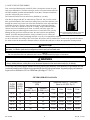
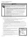
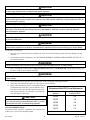
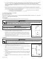
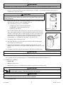
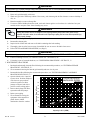
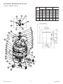
Nautilus™ NS Stainless Steel D.E. Filter
Installation, Operation & Service Manual
IMPORTANT SAFETY INSTRUCTIONS
READ AND FOLLOW ALL INSTRUCTIONS
SAVE THESE INSTRUCTIONS
Table of Contents
SECTION I.
FILTER OPERATION. .................................................................................................... 1
SECTION II.
FILTER INSTALLATION. .............................................................................................. 3
SECTION III.
TECHNICAL DATA ............................................................................................. 10 - 11
A.
REPLACEMENT PARTS ............................................................................................... 10 - 11
SECTION IV.
TROUBLE SHOOTING ............................................................................................... 12
SECTION V.
MANUAL AIR RELIEF VALVE ADDENDUM ........................................................... 13
SECTION VI.
NAUTILUS FNS & NS FILTERS REPLACEMENT KIT ............................................ 14
WARNING
Before installing this product, read and follow all warning notices and instructions accompanying this filter. Failure to follow
safety warnings and instructions can result in severe injury, death, or property damage. Call (800) 831-7133 for additional
free copies of these instructions.
Important Notice
Attention Installer.
This manual contains important information about the installation, operation and safe use of this product.
This information should be given to the owner/operator of this equipment.
SECTION I.
FILTER OPERATION.
WARNING
This filter operates under pressure. When closed properly and operated without air in the water system, this filter
will operate in a safe manner. Warning labels should be affixed to the top of the filter and on the clamp bands at
all times. Keep safety labels in good condition. Replace missing or damaged safety labels.
(For free labels call: 1-919-774-4151 or 1-805-523-2400.)
Pentair Pool Products
1620 Hawkins Ave., Sanford, NC 27330 • (919) 774-4151
10951 West Los Angeles Ave., Moorpark, CA 93021 • (805) 523-2400
Rev. B 5-14-01
R
MEMBER
NATIONAL
SPA & POOL
INSTITUTE
1
P/N 191600
A. HOW YOUR FILTER WORKS
Your vertical grid diatomaceous earth (D.E.) filter is designed to operate for years
with proper maintenance. The filter housing is made of corrosion resistant materials
and when installed, operated and maintained in accordance with these instructions,
your filter will provide years of service.
An External Air Relief Valve has been factory installed for you safety.
Your filter is charged with D.E. at initial start-up. This D.E. will cover the vertical
filter grid cloth within the filter with a thin coating. Dirty water flows from the pool
through the control valve on the side of the filter and into the lower side connection
of the filter (Item 30). The dirty water flows through the vertical grid elements
(Item 17) where dirt is filtered out by the D.E. coating. All grid elements channel
cleaned water into a manifold system (Item 13) which exits at the upper side
connection (Item 26) and through the control valve to return back to the pool. By
Filter is designed and intended for use to filter
diluting the dirty pool water with clean water, the entire pool becomes gradually
water in swimming pools and spas.
cleaned. Your filter and pump should be sized to circulate from 2 to 4 times the
volume of water in the entire pool through the filter every day to accomplish the cleaning.
As dirt is collected in the coating of D.E. in the filter, the pressure will rise and the flow of water to the pool will be reduced.
See other sections in the manual to determine when to clean the filter and how to choose the appropriate cleaning method.
CAUTION
This filter will only remove suspended matter and does not sanitize the pool. The pool must be sanitized and pH balanced for sparkling
clear water. Your filtration system must be configured and sized to meet your local health codes.
NOTE
Part no's in parenthesis refer to the replacement parts as shown in the exploded drawing on page 11 of this manual.
WARNING
Failure to operate your filter or inadequate filtration can cause poor water clarity that could obstruct visibility in your pool and can allow
diving in shallow pool area, or diving into or on top of obscured objects which can cause serious bodily injury or drowning.
Clear water is the result of proper filtration as well as proper water chemistry. Pool chemistry is a specialized area and
you should consult your local pool service specialist for specific help or instructions. In general proper pool sanitation
requires a free chlorine level of 1 to 2 PPM and a pH range of 7.2 to 7.6.
FILTER OPERATIONAL DATA
FLOW RATE
(GPM)
FILTER
MODEL
NUMBER
FILTER
MODEL
(Sq. Ft.)
NS 24
24
36
NS 36
36
NS 48
TURNOVER CAPACITY - (GALLONS)
(Based on 2.0 GPM / Sq. Ft.)
Public
Residential
1.5 GPM / Sq. Ft. 2.0 GPM / Sq. Ft.
6 Hrs.
8 Hrs.
10 Hrs.
12 Hrs.
48
17,280
23,040
28,800
34,560
54
72
25,920
34,560
43,200
51,840
48
72
96
34,560
46,080
57,600
69,120
NS 60
60
90
120
43,200
57,600
72,000
86,400
NS 72
72
108
144
51,840
69,120
86,400
103,680
P/N 191600
2
Rev. B 5-14-01
SECTION II. FILTER INSTALLATION.
A. GENERAL INFORMATION
WARNING
THIS FILTER OPERATES UNDER HIGH PRESSURE. WHEN ANY PART OF THE CIRCULATING SYSTEM,
e.g., CLAMP, PUMP, FILTER, VALVE(S), ETC. IS SERVICED, AIR CAN ENTER THE SYSTEM AND BECOME
PRESSURIZED. PRESSURIZED AIR CAN CAUSE THE LID TO BE BLOWN OFF WHICH CAN RESULT IN
SEVERE INJURY, DEATH, OR PROPERTY DAMAGE. TO AVOID THIS POTENTIAL HAZARD, FOLLOW
THESE INSTRUCTIONS.
1. BEFORE REPOSITIONING VALVE(S) AND BEFORE BEGINNING THE ASSEMBLY, DISASSEMBLY, OR
ADJUSTMENT OF THE CLAMP OR ANY OTHER SERVICE OF THE CIRCULATING SYSTEM: (A) TURN
THE PUMP OFF AND SHUT OFF ANY AUTOMATIC CONTROLS TO ENSURE THE SYSTEM IS NOT
INADVERTENTLY STARTED DURING THE SERVICING; (B) OPEN THE AIR RELIEF VALVE; (C) WAIT
UNTIL ALL PRESSURE IS RELIEVED.
2. WHENEVER INSTALLING THE FILTER CLAMP FOLLOW THE FILTER CLAMP INSTALLATION
INSTRUCTIONS EXACTLY.
3. ONCE SERVICE ON THE CIRCULATING SYSTEM IS COMPLETE FOLLOW SYSTEM RESTART
INSTRUCTIONS EXACTLY.
4. MAINTAIN CIRCULATION SYSTEM PROPERLY. REPLACE WORN OR DAMAGED PARTS
IMMEDIATELY, e.g., clamp, pressure gauge, valve(s), O-rings, etc.
5. BE SURE THAT THE FILTER IS PROPERLY MOUNTED AND POSITIONED ACCORDING TO
INSTRUCTIONS PROVIDED.
1. Check carton for any evidence of damage due to rough handling in shipment. If carton or any filter components are
damaged, notify freight carrier immediately.
2. After inspection, carefully remove filter components from carton.
3. Mount filter on a permanent slab, preferably concrete poured in a form or on a platform constructed of concrete
block or brick. DO NOT use sand to level the filter or for pump mounting, as it will wash away.
•
•
•
Provide space and lighting for routine maintenance access, see Figure 1.
DO NOT mount electrical controls over filter.
In respect for the potential for injury from any pressurized system, it is a good common sense
precaution to always stand clear of the filter whenever starting the pump.
4. If you have a Multiport Valve, assemble the valve to tank, being sure O-rings on valve fittings are in place and are
clean. Use a lubricant applied lightly, such as petroleum jelly, silicone grease, Mytilube or similar product on O-rings
and O-ring grooves prior to assembly.
5. If you have a two position slide valve, align the valve with tank so that the handle is toward the top of the tank, push
valve into ports and turn the valve nuts snugly on tank fittings. It is not necessary to cinch valve nuts to tank fitting
beyond hand tightness.
6. Assemble piping and pipe fittings to pump and valve. All piping must conform to local and state plumbing and
sanitary codes.
7. Use Teflon Tape or Pastojoint Stick on all male connections of pipe and
fittings. Use only pipe compounds suited for plastic pipe. Support pipe to
prevent strains on filter, pump or valve.
8. Long piping runs and elbows restrict flow. For best efficiency use the
fewest possible fittings, large diameter pipe (at least 1½ in. preferably 2 in.)
and locate equipment as close to the pool as possible.
9. A check valve is recommended between the filter and heater to prevent hot
water “back up” which will damage the filter and valve.
10.
The maximum operating pressure of this unit is 50 pounds per square inch,
(psi). Never operate this filter above this pressure or attach a pump to this
filter that has more than 50 psi shut off pressure.
Rev. B 5-14-01
3
Figure 1.
P/N 191600
CAUTION
Never install a chlorinator upstream of the filter or heater - always downstream and with a check valve in between the chlorinator and filter
or heater. Highly chlorinated water can damage metallic system components.
CAUTION
A positive shut off valve is NOT recommended at the outlet of the filtering system. If the system is ever run with such a valve closed, the
internal air relief system becomes inoperative and increase the risk of vessel separation. Additionally, running the system with no flow will
seriously damage the equipment.
CAUTION
A positive shut off valve is also NOT recommended at the waste port of the valve. If the system is ever run with such a valve closed, the
filter pressure will go abnormally high and increase the risk of vessel separation. Additionally, running the system with no flow will
seriously damage the equipment.
CAUTION
Never store pool chemicals within 10 ft. of your pool filter and pump. Pool chemicals are corrosive and should always be stored in a cool,
dry and well ventilated area.
WARNING
Chemical fumes and/or spills can cause severe corrosive attack to the filter and pump structural metallic components. Structurally
weakened filter components can cause filter or valve attachments to separate and could cause severe bodily injury or property damage.
B. INITIAL START-UP
1. On a new pool, clean the pool before filling with water. Excess dirt and large particles can cause damage to pump
and filter.
2. Check clamp assembly for tightness. See "FILTER DISASSEMBLY/ASSEMBLY PROCEDURES-SECTION II., C.".
for more information.
WARNING
Improper tank assembly could cause the tank top to blow off and cause severe bodily injury and / or property damage.
3. Move valve handle to filter position. Open air bleeder screw (Item 1) on the filter top. Check pump strainer pot to
be sure it is full of water. Replace pump lid.
WARNING
Air entering filter and/or the filter unit not closed correctly can cause the tank top to blow off and could cause severe bodily injury and/or
property damage.
4. Open all suction and return line valves. Stand clear of filter during the following operations.
5. Start pump. The tank will fill with water and expel air from air bleeder.
6. Remove the skimmer lid, put the recommended amount
of Diatomaceous Earth (D.E.) into the skimmer. The
Diatomaceous Earth (D.E.) Precoat Requirements
D.E. will be drawn into the filter and deposited evenly
upon the grid elements. Now the filter is providing the
Filter Model
*By Weight
pool with bright, clean water.
Number
Pounds of D.E.
CAUTION
Do not operate filter without D.E. charge for more than two minutes.
Do not use more than the recommended amount of D.E. in your filter.
Operating filter without D.E. can damage filter grid elements.
D.E. RECOMMENDATION
The amount of D.E. should be 1 pound for each 10 square feet
of filter area, see D.E. Precoat Requirements.
P/N 191600
4
NS 24
2.4
NS 36
3.6
NS 48
4.8
NS 60
6.0
NS 72
7.2
* By Weight - 1 lb. of D.E. per 10 sq. ft. of filter surface area.
Rev. B 5-14-01
7. On a new pool installation, it will require approximately one week to obtain and maintain the water clarity of which
your filter is capable. It is recommended to disassemble and clean the filter after initial pool clean up
(approximately 48 hours of operation). Follow the instructions given in this manual for disassembly, cleaning and
reassembly.
8. Be sure to note the operating pressure of the filter when it is clean and properly charged with D.E.. As the filter
removes dirt from the pool, the pressure will gradually increase. As a guide, when the pressure has increased 7 to 10
psi from the initial reading, it is time to backwash the filter.
a.
MY ORIGINAL STARTING PRESSURE IS ___________ psi (pounds per square inch). I SHOULD
BACKWASH (CLEAN) THE FILTER AT __________ psi.
C. FILTER DISASSEMBLY/ASSEMBLY
Before Disassembling Filter:
Backwash filter according to instructions under, see "FILTER BACKWASH PROCEDURE - SECTION II., F.", but stop after
instruction (# 7). Do not precoat with new D.E.
DISASSEMBLY:
1. Be sure pump is turned off and all pressure has been released from system.
WARNING
Releasing clamp with pressure on system could cause tank lid to blow off, causing severe injury or major property damage!
NEVER adjust, tighten or loosen “V” band clamp when tank is under pressure!
2. Remove filter drain plug and drain all water from tank.
WARNING
Clamp hardware and filter surface could have sharp edges which can cause bodily injury if
improperly handled. Please use caution when performing the following procedures.
3. Loosen clamp nuts alternately until one is removed. Remove spring and washers
noting part orientation. Lift clamp assembly off of filter.
4. Tank halves may have a tendency to stick together. In order to separate tank
halves, it may be necessary to strike the tank top using the palm of your hand
with a glancing upward movement, see Figure 2. Proceed gradually around the
tank using this motion until the top loosens.
5. Being careful not to damage tank seal, lift upper tank shell off of lower tank shell.
Figure 2.
ASSEMBLY:
WARNING
Always visually inspect filter components during normal servicing to insure structural safety. Replace any item which is
corroded, bent or otherwise visually deteriorated. Deteriorated filter components can allow the filter top or attachments to
blow off and could cause severe bodily injury or property damage.
1. Thoroughly clean air relief filter screen on top of manifold EVERY time filter is
opened. Be sure to remove all debris from screen.
2. Inspect tank seal, (Item 21), for cuts, nicks, etc. If damaged, replace with a new
one.
3. Clean tank seal area of tank shell (both halves) and tank seal.
4. Inspect, clean and lubricate the O-ring, (Item 18), on the upper pipe assembly,
(Item 19).
5. Clean the metal band which supports the tank seal on the inside of the filter tank.
Note that this band has a formed bead in its center to locate it in the assembled
tank, see Figure 3.
6. Lubricate the tank seal with petroleum jelly, silicone grease, Mytilube or similar
product.
Rev. B 5-14-01
5
Figure 3.
P/N 191600
7. Carefully install tank seal and upper tank shell.
CAUTION
Be sure upper tank shell contacts tank seal surface evenly and seal area is clean and free from dirt, etc. Debris on seal surfaces can cause
leaks.
8. Install clamp springs, washers and units. Tighten nuts evenly and alternately until spring coils touch each other. Tap
clamp around tank with rubber hammer to assist seating of clamp.
9. Use only those components supplied with filter or Pentair Pool Products replacement parts when dealing with the
bands and spring tensioning devices.
WARNING
Use of non original equipment parts on band clamps with spring tensioning devices may cause these tensioning devices to
malfunction. Improper clamp installation could cause the filter top to blow off and cause severe personal injury and/or
property damage.
WARNING
Do not over tighten the clamp band. Tightening the clamp band beyond recommended procedures may damage the
clamp band and cause unexpected failure, sudden release of pressure and injury or damage.
Over tightening may also deform tank seal, causing leakage at band clamp. Corroded components cannot be
repaired and must be replaced. If you are experiencing corrosion, consult your pool service company or dealer.
D. FILTER CARE
1. Keep pool water pH at the recommended levels (7.2 to 7.6) as well as other pool chemicals at their proper levels to
avoid deterioration of the stainless steel tank.
2. The tank is stainless steel, but is not corrosion proof if the pool chemistry is allowed to act aggressively. Under such
conditions the steel can experience pitting which will be most apparent in the flange area where the O-ring seats and
seals the two halves of the filter.
3. To minimize this tendency, it is recommended to keep the flanges clean of surface corrosion by removing any
corrosion with fine emery cloth or stainless steel wool (DO NOT use steel wool) and coat the O-ring with a
substance such as petroleum jelly, silicone grease, Mytilube or a similar product.
4. If corrosion is allowed to progress, the filter will eventually leak at the O-ring seal. This process cannot be arrested
or corrected by tightening the closure band, though that may temporarily stop the leak.
E. CLEANING FREQUENCY
1. The filter on a new pool should be backwashed, disassembled and cleaned after approximately 48 hours of operation
to clean out plaster dust and/or construction debris.
2. Once a new pool has been established, the dirt collected will gradually increase the filter pressure. When the filter
pressure increases 7 to 10 psi over the initial pressure or when the flow has been reduced by about 1/3 from when
the filter was clean, it is time to backwash the filter. Different areas and water conditions will have different normal
cleaning intervals.
3. If at any time the starting pressure after backwashing the filter indicates 2 to 6 psi higher than normal starting
pressure, it is time to perform a manual filter cleaning or a chemical cleaning procedure in the worst cases.
4. It is a good idea to disassemble the filter and perform a chemical leaning procedure twice a year to remove
accumulated body oils, etc.
5. In areas that have freezing winter temperatures protect equipment by backwashing and either manually cleaning or
chemically cleaning before winter storage. Be sure all water is drained from the filter using the drain plug. The air
bleeder must be opened as well as all other valves.
P/N 191600
6
Rev. B 5-14-01
F. FILTER BACKWASH PROCEDURE
NOTE
When backwashing with a separation tank, see Separation Tank Owner’s Manual for instructions.
1. Stop pump. Ensure that the backwash line is open and any valving is adjusted to allow the free flow of water.
2. Change valve positions.
a.
If using Multiport Valve, set to backwash position.
b.
If using Two-Position Slide Valve, raise handle to fully extended position.
3. Stand clear of filter.
4. Start pump, this will circulate water backwards through the filter to flush D.E. cake and contaminants into the
separation tank or to waste.
5. If system has a sight glass, backwash until water in glass runs clear.
6. If system does not have a sight glass:
a.
Backwash one minute.
b.
Stop pump and change valve position.
1.) If using Multiport Valve, set to rise position.
2.) If using Two-Position Slide Valve, push handle down to filter position.
WARNING
To prevent equipment damage and possible bodily injury and/or property damage, always turn the pump off before changing the valve
positions.
c.
Stand clear of filter.
d.
Restart pump, run for one minute.
e.
Repeat steps a,b,c and d three times.
Cycling is effective when D.E. cake and contaminants are difficult to break and flush out of the filter.
NOTE
Do not vacuum pool while backwashing filter.
7. Stop pump.
8. Open air bleeder screw and release all pressure from tank and system.
9. Follow “INITIAL STARTUP - SECTION II., B." procedure to restart system.
10. Compare pressure reading on gauge with reading recorded after initial start-up. The two readings should be very
close; if not, do “Manual Filter Cleaning Procedure”.
G. MANUAL FILTER CLEANING
NOTE
At least once a year, disassemble and clean filter regardless of operating pressure readings. This can be done conveniently while winterizing
pool in cold climates. Use this method regularly if no means of backwashing is available.
BEFORE DISASSEMBLING FILTER:
1. Backwash filter as recommended but do not precoat with new D.E..
2. STOP PUMP.
3. OPEN air bleeder screw.
4. WAIT until all pressure is released from filter tank and system before loosening clamp.
WARNING
Releasing clamp with pressure on system could cause tank lid to blow off, causing severe injury or major property damage!
Never adjust, tighten or loosen “V” band clamp when tank is under pressure!
5. Disassemble Filter, see "FILTER DISASSEMBLY/ASSEMBLY - SECTION II., C.".
Rev. B 5-14-01
7
P/N 191600
WARNING
To avoid severe injury or property damage, exactly follow instructions under, see "FILTER DISASSEMBLY/ASSEMBLY- SECTION II., C. ".
6. Grasp element assembly at top manifold using hand holds and lift to remove it, see Figure 4.
7. Hose down element assembly and clean with bottle brush, see Figure 5. Use detergent solution or filter cleanser
available from a pool service store.
CAUTION
To avoid damaging fabric, do not allow filter element to rub on concrete or any abrasive surface
during cleaning. Do not expose element cloth to direct sun for long periods. Direct sun will cause
the cloth to deteriorate.
8. Inspect grid cloth for tears, calcification, plugged areas, etc. If necessary, soak
element in filter cleanser to remove buildup of oils, etc.
One of the following cleaners is recommended:
• FILTER-CLEANSE - Great Lakes Biochemical
• FILTER-FREE - Hydrotech Chemical Corp.
• KLEEN-IT - Bio Lab, Inc.
Figure 4.
Mix a solution following the manufacturer’s instructions on the label. Place the
entire grid assembly in a plastic container and add the solution so the entire grid
assembly is submerged. Allow to stand overnight (12 hours). The following day
wash with a hose and remove all of the solution from the grids so it does not
return to the pool. If calcified, perform the chemical cleansing procedure
described under, see "CHEMICAL CLEANING - SECTION II., H.".
9. Thoroughly clean air relief filter screen.
10. With filter drain open, hose down the internal portion of filter and thoroughly
clean sealing area of tank halves.
11. Replace the grid-assembly by setting the manifold opening directly over the
connector pipe. Push down on the grid assembly and check to see that it is seated
properly.
12. Thoroughly clean drain plug seal and sealing area and replace and tighten plug.
Figure 5.
WARNING
To avoid severe injury or property damage, exactly follow instructions under, see "FILTER DISASSEMBLY/ASSEMBLY- SECTION II., C.".
13. If unit is returning to service, see "INITIAL STARTUP - SECTION II., B.".
14. If cleaning is part of seasonal shutdown, see "WINTERIZING PROCEDURE- SECTION II., I.".
H. CHEMICAL CLEANING
1. STOP PUMP.
2. OPEN air bleeder screw.
3. WAIT until all pressure is released from filter tank and system before loosening clamp.
WARNING
Releasing clamp with pressure on system could cause tank lid to blow off, causing severe injury or major property damage!
Never adjust, tighten or loosen “V” band clamp when tank is under pressure!
CAUTION
To avoid damaging fabric, do not allow filter element to rub on concrete or any abrasive surface during cleaning. Do not expose element
cloth to direct sun for long periods. Direct sun will cause the cloth to deteriorate.
4. Disassemble Filter.
P/N 191600
8
Rev. B 5-14-01
WARNING
To avoid severe injury or property damage, exactly follow instructions under, see "FILTER DISASSEMBLY/ASSEMBLY- SECTION II., C.".
5. Disassemble and inspect element grid assemblies for tears and worn areas. Replace as needed.
6. Rinse each grid thoroughly with water.
7. Wash each grid with a mild soap solution. If necessary, soak element grids in filter cleanser to remove buildup of
oils, etc.
8. Rinse thoroughly to remove all soap film.
9. To remove mineral buildup from filter cloth, soak each element grid two to four hours in a solution of one part
muriatic acid to ten parts water. Some foaming may occur.
WARNING
Working with muriatic acid can be dangerous. When cleaning elements always wear rubber gloves and eye
protection. Add acid to water, do not add water to acid. Splashing or spilling acid can cause severe personal injury
and/or property damage.
10.
Rinse each element grid thoroughly with water.
11.
Reassemble element grids.
12.
Inspect inside of filter tank and remove all debris remaining after backwashing.
13.
Thoroughly clean air relief screen on top of manifold. Be sure to remove all debris from screen.
14.
Follow FILTER ASSEMBLY PROCEDURE, see (Page 5).
WARNING
To avoid severe injury or property damage, exactly follow instructions under, see "FILTER DISASSEMBLY/ASSEMBLY- SECTION II., C. ".
15.
If unit is returning to service, see "INITIAL START-UP - SECTION II., B.".
16.
If cleaning is part of seasonal shutdown, see "WINTERIZING PROCEDURE - SECTION II., I.".
I. WINTERIZING PROCEDURE
1. Backwash and manually clean the filter following the recommended procedures, see "FILTER BACKWASH
PROCEDURE - SECTION II., F.".
2. We recommend removing the internal grid assembly and store in a dry area.
3. Reassemble the filter following the recommended procedures, see "FILTER DISASSEMBLY/ASSEMBLY
PROCEDURE-SECTION II., C.".
5. Remove drain plugs from filter,
separation tanks and pumps.
6. Drain system piping.
7. We recommend covering the
equipment with a tarpaulin or
plastic sheet to inhibit
deterioration from the weather.
Pressure Drop Curves for
NAUTILUS D.E. FILTERS
FORM 455 REV. 9/91
40
Pressure Drop in Feet
4. Open air bleeder valve. Open all
system valves. Position multiport
valve between port positions
(winterize position) to allow
passage to all ports and relieve
pressure on the sealing gasket.
35
30
72
NS
25
NS
20
15
NS
10
48
NS
4
NS 2
5
0
36
60
0
10
20
30 40 50 60 70 80 90 100 110 120 130 140 150
Capacity in U.S. (GPM)
Rev. B 5-14-01
9
P/N 191600
SECTION III. TECHNICAL DATA
A. REPLACEMENT PARTS
QTY.
ITEM
P/N
BLEEDER
1
24
194893
SPACER - 2 in . EXTERNAL
1
273513
O- RI N G - BLEEDER
1
25
192320
O- RI NG - BULKHEAD
1
26
194801
BULKHEAD - 2 in . W/ GROOVE
1
27
273550
AI R RELI EF ASSY.
1
28
154722
F OOT- NS/ PF
1
29
195829
PLUG - 2 in . DRAI N
1
30
194913
PI PI NG ASSY. LOWER W/ DRAI N
1
31
192256
SHELL - BOTTOM NS 24/ 36
1
31
192257
SHELL - BOTTOM NS 48
1
ITEM
P/ N
1
273506
2
DES CRIPTION
DESCRIPTION
QTY.
3
273501
CAP
1
4
272546
LABEL, WARN I N G
1
5
273555
VALVE BODY - MACHI N ED
1
6
155050
PRESSURE GAUGE
1
7
154492
O- RI N G
2
10
194996
LABEL, WARN I N G
2
11
273502
SPACER- TOP
1
12
273505
SPACER
1
13
194908
BULKHEAD N UT
1
31
192260
SHELL - BOTTOM NS 60
1
14
152128
RETAI N ER - 18 in . DI A. S/ S O- RI N G
1
31
192259
SHELL - BOTTOM NS 72
1
15
192328
GRI D - PARTI AL N S 24
1
32
154747
SPACER - 2. 8 in . DI A. x ¼ in . P. V. C.
1
15
192330
GRI D - PARTI AL N S 36
1
33
194908
NUT - 2 in . BULKHEAD
1
15
192332
GRI D - PARTI AL N S 48
1
34
192013
NUT - 5/ 16 in . - 16 S/ S
4
15
192334
GRI D - PARTI AL N S 60
1
35
639822
WASHER - 5/ 16 in . S/ S F LAT
4
15
195059
GRI D - PARTI AL N S 72
1
36
192194
RETAI NER GRI D
1
16
192186
GRI D - F ULL N S 24
7
37
152126
BAND ASSY. COMPLETE
1
16
192187
GRI D - F ULL N S 36
7
38
192182
ROD- 5/ 16 in . x 15½ in . Ma n ifo ld Reta in er NS 24
2
16
192188
GRI D - F ULL N S 48
7
16
192189
GRI D - F ULL N S 60
7
38
192183
ROD- 5/ 16 in . x 21½ in . Ma n ifo ld Reta in er NS 36
2
16
195058
GRI D - F ULL N S 72
7
38
192184
ROD- 5/ 16 in . x 27½ in . Ma n ifo ld Reta in er NS 48
2
17
192324
GRI D - ASSY. - COMPLETE N S 24
1
38
192185
ROD- 5/ 16 in . x 33½ in . Ma n ifo ld Reta in er NS 60
2
17
192325
GRI D - ASSY. - COMPLETE N S 36
1
38
195002
ROD- 5/ 16 in . x 39½ in . Ma n ifo ld Reta in er NS 72
2
17
192326
GRI D - ASSY. - COMPLETE N S 48
1
39
194990
WASHER, NS SMALL I D ( . 890 OD, . 320 I D)
2
17
192327
GRI D - ASSY. - COMPLETE N S 60
1
40
194992
SPRI NG, NS
2
17
195060
GRI D - ASSY. - COMPLETE N S 72
1
41
194991
WASHER, NS LARGE I D ( . 890 OD, . 430 I D)
2
18
192323
O- RI N G
1
42
194993
NUT, MACHI NED
2
19
194981
PI PI N G ASSY. - UPPER N S 24
1
43
172855
STRAI NER - AI R VENT
1
19
194982
PI PI N G ASSY. - UPPER N S 36
1
44
154603
LABEL - WARNI NG
1
19
194983
PI PI N G ASSY. - UPPER N S 48
1
46
192276
SHELL - TOP F I LTER NS 24 W/ 2 3/ 8 in . DI A. HOLE
1
19
194984
PI PI N G ASSY. - UPPER N S 60
1
46
192277
SHELL - TOP F I LTER NS 36/ 60 W/ 2 3/ 8 DI A. HOLE
1
19
194985
PI PI N G ASSY. - UPPER N S 72
1
20
152121
BAN D ASSY.
1
46
192278
SHELL - TOP F I LTER NS 48/ 72 W/ 2 3/ 8 in . DI A. HOLE
1
21
152127
O- RI N G - 18 in . DI A. TAN K
1
46
152255
SHELL - TOP F I LTER NS 24 W/ AI R RELI EF
1
22
194903
BTM - SHELL N S 24 W/ PI PI N G & F OOT
1
46
192190
SHELL - TOP F I LTER NS 36/ 60 W/ AI R RELI EF
1
22
194904
BTM - SHELL N S 36 W/ PI PI N G & F OOT
1
46
192214
SHELL - TOP F I LTER NS 48/ 72 W/ AI R RELI EF
1
22
194905
BTM - SHELL N S 48 W/ PI PI N G & F OOT
1
47
192193
MANI F OLD GRI D - COMPLETE
1
22
194912
BTM - SHELL N S 60 W/ PI PI N G & F OOT
1
191600
MANUAL - I NSTRUCTI ON
1
22
194907
BTM - SHELL N S 72 W/ PI PI N G & F OOT
1
23
154492
O- RI N G - 2 in . BULKHEAD
2
P/N 191600
10
Rev. B 5-14-01
SECTION III. TECHNICAL DATA, cont'd.
A. REPLACEMENT PARTS
A DIM
B DIM
C DIM
MODEL
INCHES METRIC INCHES METRIC INCHES METRIC
2
3
5
1
NS - 24
43
1092 mm 33 1/8
841 mm
28 ½
724 mm
NS - 36
49
1245 mm 39 7/8
1013 mm
34 ½
876 mm
NS - 48
61
1550 mm 45 7/8
1165 mm
40 ½
1023 mm
NS - 60
67
1702 mm 51 7/8
1318 mm
46 ½
1181 mm
NS - 72
81
2057 mm 57 7/8
1470 mm
52 ½
1334 mm
6
27
4
11
7
7
34
12
35
13
43
46
47
15
44
42
16
17
41
40
18
39
19
20
36
21
37
35
14
10
34
38
33
22
32
31
23 24
25
30
26
23
28
29
18
Rev. B 5-14-01
11
P/N 191600
SECTION IV. TROUBLE SHOOTING
S YM P T O M S
D. E . Lea k in g Ba ck T o Po o l
Po o l Wa t er N o t S u f f icien t ly Clea n
Hig h F ilt er Pressu re Af t er Ba ck wa sh in g
Ret u rn F lo w T o Po o l Dim in ish ed
Lo w F ilt er Pressu re
S h o rt F ilt er Cy cles
Lea k a g e a t cl a m p
P/N 191600
WH A T TO L O O K FO R
RECO M M END ED A CTIO N
Af t er b a ck wa sh in g a n d re- co a t in g t h e f ilt er wit h
DE . , so m e a m o u n t o f "p u f f b a ck " is n o rm a l.
T h e D. E . will en en t u a lly b e f ilt ered o u t o f t h e
p o o l. N o a ct io n n ecessa ry .
Da m a g ed Grid o r O- rin g in f ilt er a ssem b ly .
Rep la ce d a m a g ed g rid s o r O- rin g s.
I m p ro p er a ssem b ly o f in t ern a l p a rt s.
Co rrect a ssem b ly o f p a rt s.
M i s s i n g o r d ef ect i ve ch eck va l ve.
I n st a ll o r rep a ir ch eck va lve.
I m p ro p er p reco a t o f D. E . o n g rid s.
Use reco m m en d ed a m o u n t o f D. E .
I n a d eq u a t e t u rn o ver ra t e.
Co n su lt d ea ler o r p o o l service t ech n icia n .
Po o l ch em ist ry n o t a d eq u a t e t o in h ib it a lg a e
g ro wt h .
Ma in t a in p o o l ch em ist ry o r co n su lt p o o l service
t ech n i ci a n .
I n su f f icien t b a ck wa sh in g .
Ba ck wa sh u n t il ef f lu en t ru n s clea r.
F ilt er clo t h p lu g g ed wit h D. E . a n d co n t a m in a n t s.
Ma n u a lly clea n f ilt er g rid s.
F ilt er clo t h p lu g g ed wit h m in era l d ep o sit s.
Ch em ica lly clea n f ilt er g rid s.
Pa rt ia lly clo sed va lve o r rest rict io n in ret u rn lin e.
Op en va lve o r rem o ve o b st ru ct io n in lin es.
Ob st ru ct io n in p u m p h a ir a n d lin t st ra in er.
Clea n b a sk et in st ra in er.
Ob st ru ct io n in p u m p .
Di s a s s e m b l e a n d c l e a n p u m p .
Ob st ru ct io n in su ct io n lin e t o p u m p .
Clea n sk im m er b a sk et . Rem o ve o b st ru ct io n in
l i n e s . Op e n v a l v e s i n s u c t i o n l i n e .
I m p ro p er b a ck wa sh .
Ba ck wa sh u n t il ef f lu en t ru n s clea r.
Po o l ch em ist ry n o t a d eq u a t e t o in h ib it a lg a e
g ro wt h .
Ma in t a in p o o l ch em ist ry o r co n su lt p o o l service
t ech n i ci a n .
I m p ro p er p reco a t o f D. E . o n g rid s.
Use reco m m en d ed a m o u n t o f D. E .
Plu g g ed g rid s.
Ma n u a lly clea n o r ch em ica lly clea n a s req u ired .
F lo w ra t e t o o h ig h .
Rest rict f lo w t o ca p a cit y o f f ilt er.
Imp ro p er to rq u e o n clo su re b a n d h a rd wa re.
Rea ssemb le cla mp fo llo win g p ro ced u re u n d er
"Assemb ly ".
Deb ris co n ta min a tio n o n O-rin g a n d fla n g es.
Clea n O-rin g a n d fla n g es. Lu b rica te O-rin g .
Cu t o r d a ma g ed O-rin g .
Rep la ce O-rin g .
Co rro sio n p its o n fla n g es.
Rep la ce ta n k a n d co n su lt p o o l service tech n icia n fo r
so u rce o f co rro sio n .
12
Rev. B 5-14-01
SECTION V. MANUAL AIR RELIEF VALVE ADDENDUM
ADDENDUM: FOR USE WITH MANUAL AIR RELIEF VALVE
IMPORTANT SAFETY INSTRUCTIONS
READ AND FOLLOW ALL INSTRUCTIONS
SAVE THESE INSTRUCTIONS
If your filter is equipped with a Manual Air Relief Valve at the top; note the following important corrections and
deletions in this manual:
Page 2, Section A., Paragraph 3 and Illustration 1. This paragraph and illustration are not applicable to your filter.
Page 4, Section C., Subsection 5. The note regarding water and/or mist escaping is not applicable to your filter.
The air bleeder screw should be closed only after a steady stream of water comes out from the bleeder hole.
Page 5, Section D., Subsection Assembly, Paragraph 2. This paragraph regarding External Air Relief Filter
Element is not applicable to your filter.
Pages 8 & 9, Section I. Disregard this entire section. It is not applicable to your filter.
Pages 10 & 11, Section K. The following items are not applicable to your filter:
ITEM
P/N
3
273501
DESCRIPTION
CAP
4
272042
UMBRELLA VALVE (MAY ALSO BE LISTED AS P/N 273507)
8
273514
O-RING, FLOAT
9
273504
FLOAT
10
273503
RETAINER, FLOAT
45 (NS)
273508
FILTER CLOTH ELEMENT (MAY ALSO BE LISTED AS P/N 273519)
14 (FNS)
273508
FILTER CLOTH ELEMENT (MAY ALSO BE LISTED AS P/N 273519)
12 (INS)
273508
FILTER CLOTH ELEMENT (MAY ALSO BE LISTED AS P/N 273519)
The Replacement Parts listing in your Filter’s Operation Manual reflects part numbers for black parts on the
External Air Relief. Use the following table in ordering replacement parts for your External Air Relief. DO NOT
substitute black body assemblies for other colored body assemblies. Unauthorized substitution may result in a
non-sealing filter that could flood the filter installation area.
ITEM
LISTED
BLACK P/N
DESCRIPTION
GREY
P/N
TAN
P/N
1
273506
BLEEDER SCREW
273556
273546
5
273515
BODY MACHINED
273555
273545
*11
273502
TOP SPACER
273552
273542
27 (NS)
273510
BODY ASSEMBLY
273550
N/A
49 (FNS)
273510
BODY ASSEMBLY
273550
N/A
46 (INS)
273510
BODY ASSEMBLY
273550
N/A
NS (Stainless Steel) and FNS (Fiberglass) Filters only. This part number not used on INS (Polymeric) Filters.
Rev. B 5-14-01
13
P/N 191600
SECTION VI. NAUTILUS FNS & NS FILTERS REPLACEMENT KIT
A. CLAMP KIT INSTALLATION
1. Remove contents of kit and check against parts list at end of instructions to insure all components are present.
2. Backwash filter according to instructions under, see “FILTER BACKWASH PROCEDURE" - SECTION II., F," in
your filter manual: INSTALLATION, OPERATION & SERVICE MANUAL. Stop after instruction #7. Do not
precoat with new D.E.
3. Be sure pump is turned off and all pressure has been released from system.
WARNING
Releasing clamp with pressure on system will cause tank lid to blow off, causing severe injury or major property damage!
NEVER adjust, tighten or loosen “V” band clamp when tank is under pressure!
4. Remove filter drain plug and drain all water from tank.
CAUTION
Clamp hardware and filter surface could have sharp edges which can cause bodily injury if improperly handled. Please use caution when
performing the following procedures.
5. Loosen clamp nuts alternately until one is removed. Lift clamp assembly off of filter.
NOTE
If you are installing one of the following replacement kits, remove tank top at this point and refer to AIR RELIEF INSTALLATION on next page;
Kit P/N 181013, 181014, 181015, 181016, 181017, 181018, 181019, 181020, 181021, and 181022.
6. Remove second nut from clamp assembly. If replacing
entire band assembly (Kit: P/N 181011 for NS and
Kit: P/N 181012 for FNS), the old band should be
discarded and the following instructions will apply to
installation of the new band assembly. The threaded end
of the T-bolt should protrude through the trunnion per
Figure 1.
7. Place one of the washers (with the small hole 5/16 in.
inside diameter) on the threaded end of the T-bolt and
slide washer down bolt until it is against the trunnion,
Figure 1.
see Figure 1.
8. Place one of the washer (with the large hole- 7/16 in. inside diameter
for NS and 17/32 in. inside diameter for FNS) over the shank of the
SPRING
brass nut. Place one of the springs over the shank of the brass nut so
that the washer with the large hole is captured between the end to the
spring and the head of the brass nut, see Figure 2.
9. Thread shank of nut onto T-bolt, 2 turns maximum.
10. Preassemble second washer with large hole, nut and spring for opposite
SHANK
side of opposite side of band clamp assembly.
11. Insure flanges on tank halves are free of dirt and or D.E.
Figure 2.
12. Place clamp around tank flange making sure threaded end of T-bolt
protrudes through trunnion as in Figure 1.
13. Place remaining washer (with the small hole 5/16 in.
PULL BAND HALVES
inside diameter) on the threaded end of the T-bolt and
A
APART UNTIL NO GAP
slide washer down bolt until it is against the trunnion,
EXISTS AT "A" OR
BETWEEN SPRING
see Figure 1.
AND WASHERS.
14. Thread shank of nut onto T-bolt 2 turns minimum. If
end to T-bolt does not protrude through trunnion far
enough to engage shank of nut, make sure that first
spring assembly is tight against trunnion per Figure 3,
and band is tight against tank.
Figure 3.
P/N 191600
14
WASHER
NUT
Rev. B 5-14-01
15.
16.
Tighten nuts evenly and alternately until spring coils touch each other. Tap clamp around tank with rubber hammer to
assist seating of clamp.
Use only those components supplied in this kit or Pentair Pool Products replacement parts when dealing with the
hands and spring tensioning devices.
WARNING
Use of non original equipment parts on band clamps with spring tensioning devices may cause these tensioning devices to
malfunction, resulting in improper clamp installation. Could cause the filter top to blow off and cause severe personal injury
and/ or property damage.
WARNING
Do not over tighten the clamp band. Tightening the clamp band beyond recommended procedures may damage the clamp band and
cause unexpected failure, sudden release of pressure and injury or damage.
17.
Follow instructions under “INITIAL START-UP - SECTION II., B.” of your filter INSTALLATION, OPERATION
& SERVICE MANUAL to return your filter to operation.
B. AIR RELIEF INSTALLATION
1. Make sure steps 1 through 5 outlining pump shut down and clamp
removal have been completed.
NEW 2-3/8"
DIAMETER HOLE
2. Thoroughly clean air relief filter screen on top of manifold. Be sure to
remove all debris from screen.
3. Inspect tank seal for cuts, nicks, etc. If damaged, replace with a new
one.
4. Prepare tank top for alteration by removing existing air bleeder assembly
and cleaning tank top inside and out. If you received a new top with the
2-3/8 in. diameter hole in it, skip to step 8.
EXISTING 13/32"
DIAMETER HOLE
Figure 4.
5. For FNS (Fiberglass) tanks, use a 2-3/8 in. diameter hole saw to carefully cut a larger hole in the tank top. The 2-3/8
in. diameter hole should be centered on the original 13/32 in. diameter hole as shown in Figure 4.
CAUTION
Do not allow hole saw to scratch the outside surface of the tank top past the new 2-3/8 in. Diameter hole. This is an o-ring sealing surface
and scratches in this area will cause the o-ring sealing surface and scratches in this area will cause the o-ring seal to leak.
6. Using heavy gloves and a dust mask (same as used for installing fiberglass insulation) for protection, carefully
remove any loose fibers from the hole. Lightly sand the inside of the hole with a 200-220 grit non-clogging sand
screen such as Carborundum Abrasives’ S/C Sand Screen M755S silicone carbide 220 grit. DO NOT enlarge the
hole past 2-13/32 in. diameter.
CAUTION
The sanding operation will generate glass fibers and loose dust. Protect yourself from these by the use of gloves and mask as noted in #6
above. Without these protective items, glass fibers and loose dust could be imbedded in the skin and/ or inhaled, possibly causing injury
and or irritation.
7. For NS (Stainless Steel) tanks, a good quality steel punch must be used to make the larger hole. It may be necessary
to use 2 punches; (1) to enlarge the hole from 13/32 in. diameter to accommodate a larger mandrel for the 2-3/8 in.
diameter punch and (1) 2-3/8 in. diameter punch. The punches must be capable of punching though .060 thick steel.
Follow punch in making the larger hole. The 2-3/8 in. diameter hole should be centered on the original 13/32 in.
diameter hole as shown in figure 4. The final hole size should be 2-3/8 in. diameter minimum and 2-13/32 in. diameter
maximum. Remove any metal burrs in the hole with a file.
CAUTION
Do not allow punch or file to scratch the outside surface of the tank top past the new 2-3/8 in. Diameter hole. This is an o-ring sealing
surface and scratches in this area will cause the o-ring to leak. Do not enlarge the hole past 2-13/32 in. Diameter. Do not use a hole saw to
modify stainless steel tanks.
8. Remove Air Relief from box and check parts list at end of instructions to insure that all the components are present.
Rev. B 5-14-01
15
P/N 191600
9. Lightly lubricate O-Ring, (Item 7) with Dow Corning #203 silicone lubricant or
similar product, and place them in appropriate O-Ring grooves on Air Relief Body,
(Item 5) and Top Spacer, see (Item 1). See Figure 5, for assembly sequence and
part location. Note items 1 through 5 are pre-assembled for ease for installation.
Note that flat side of Bottom Spacer, (Item 12) goes against Securing Nut (Item 13).
11.
Once Air Relief Assembly has been installed, tighten Securing Nut with tool P/N
151603 while holding Air Relief Body securely. An alternate method of tightening the
body is to tighten the nut hand tight and then rotate the body clockwise to tighten.
1
6
7
4
If your kit is equipped with a new Bracket Support, replace the existing Bracket
Support on your Grid Assembly per following instruction steps 12 through 17. If
not, skip to step 18.
12
13
Remove Air Screen and ¼ in. diameter tube from top of manifold.
13.
Redrill ¼ in. diameter hole per, see Figure 6 below.
14.
Remove nuts and lock washers holding down original Bracket Support and remove
support.
Fill original ¼ in. diameter hole
with silicone sealer and place
new Bracket Support in
position so that the holes in the
Bracket Support line up with
the holes in the Manifold that
the retaining rods pass through.
Push retaining Rod up through
hole in Manifold and new
Bracket Support and secure
with lock washers and nut.
Repeat for second Retaining
Rod.
Place original Air Screen and
Tube into new ¼ in. diameter
hole.
Clean Tank Seal area of Tank
Shell (both halves) and Tank
Seal.
Lubricate the Tank O-Ring
DRILL 1/4"
with petroleum jelly, silicone
HOLE
grease, or similar product.
Carefully install Tank O-Ring
and upper Tank Shell.
16.
18.
19.
20.
Figure 2.
LIFT HERE
17.
11
7
12.
15.
5
LIFT HERE
10.
3
2
1"
CAUTION
Be sure upper Tank Shell contacts seal
surface evenly and seal area is clean and
free from dirt, etc.
21.
3/8"
Go to step 6 of CLAMP KIT
INSTALLATION on front page to continue installation.
Figure 6.
SAVE THESE INSTRUCTIONS.
Pentair Pool Products
1620 Hawkins Ave., Sanford, NC 27330 • (919) 774-4151
10951 W. Los Angeles Ave., Moorpark, CA 93021 • (805) 523-2400
P/N 191600
16
Rev. B 5-14-01