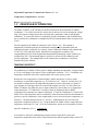
1
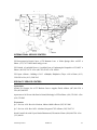
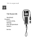
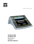
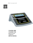
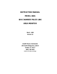
YSI Model 30
Salinity, Conductivity and
Temperature System
Service Manual
TABLE OF CONTENTS
Section 1 General Description
1
1.1 Service Philosophy
1.2 Specifications
1.3 Principles of Operation
1
2
3
Section 2 Making Measurements
2.1 Advanced Setup
4
6
Section 3 Measurement Errors
8
Section 4 Maintenance
10
Section 5 Instrument Test Procedure
12
Section 6 System Calibration
13
Section 7 Troubleshooting
15
Section 8 Disassembly Procedures
8.1 Assembly Drawing
8.2 Board Assemblies
8.3 Circuit Diagrams
8.4 Feature Customization
16
17
18
19
21
Appendix A Parts List (Board Components)
Appendix B Accessories & Replacement Parts
Appendix C Warranty and Repair
22
23
24
i
ii
SECTION 1
GENERAL DESCRIPTION
The YSI Model 30 Handheld Salinity, Conductivity and Temperature System is a rugged, microprocessor based, digital meter with an attached YSI four electrode conductivity cell.
The YSI Model 30 is designed for use in field, lab, and process control applications and is available
with cable lengths of 10, 25 or 50 feet. The body of the probe has been manufactured with
stainless steel to add rugged durability and sinking weight. The large liquid crystal display (LCD)
is easy to read, and is equipped with a back-light for use in dark or poorly lighted areas.
The Model 30's micro-processor allows the system to be easily calibrated with the press of a few
buttons. Additionally, the micro-processor performs a self-diagnostic routine each time the
instrument is turned on.. The self-diagnostic routine provides you with useful information about
the cell constant, function of the instrument circuitry, and the quality of the readings you obtain.
For a list of these diagnostic features, see Section 7, Troubleshooting.
The system simultaneously displays temperature (oC is factory default, non-CE units can be
modified to read in oF, see section 8.4, Feature Customization), along with one of the following
parameters: conductivity; temperature compensated conductivity; (in µS/cm or mS/cm), and
salinity (in parts per thousand [ppt]). Though calibration is NOT required, a single calibration will
adjust the instrument, regardless of which parameter you wish to read. You can switch back and
forth from salinity, conductivity, and temperature compensated conductivity with a single push of
the MODE key.
A probe storage chamber is built into the instrument. This chamber provides a convenient place to
store the probe when the system is not in use, and provides protection for the electrodes within the
probe.
The instrument is powered by six AA-size alkaline batteries. A new set of alkaline batteries will
provide approximately 180 hours of continuous operation. When batteries need to be replaced, the
LCD will display a "LO BAT" message.
The YSI Model 30 instrument case is waterproof (rated to IP65). You can operate your Model 30
in a steady rain without damage to the instrument.
1.1
SERVICE PHILOSOPHY
The YSI Model 30 is sold as a complete conductivity measuring system including an attached
probe and either a 10, 25 or 50-foot cable. Most service issues that occur in conductivity systems
are caused by improper maintenance of the probe and/or cable. For this reason, troubleshooting
efforts should be initially directed at determining the condition of the probe and cable.
YSI Incorporated
Model 30
1
In the event that a service problem is isolated to the meter itself, YSI recommends replacement of
the entire defective sub-assembly rather than the individual components. All replacement
components are available through YSI; see Appendix C, Warranty & Repair.
In most cases, the recommended method of determining a sub-assemblies condition is by
substitution. For example ; to test for a defective probe/cable assembly substitute the assembly
with a known good assembly or a decade resistance box using Section 5, Instrument Test
Procedure. If, after testing, the PCB meets the established specifications, the probe/cable
assembly will have to be serviced or replaced.
1.2
SPECIFICATIONS
Operating Environment
Medium: fresh, sea, or polluted water and most other liquid solutions.
Temperature: -5 to +95oC
Depth: 0 to 10, 0 to 25, or 0-50 feet (depending on cable length)
Storage Temperature: -10 to +50oC
Material: ABS, Stainless Steel, and other materials.
Dimensions:
Height: 9.5 inches
(24.13 cm)
Thickness:
2.2 inches
(5.6 cm)
Width:
3.5 inches max.
(8.89 cm)
Weight:
1.7 pounds (w/ 10’ cable )
(.77 kg)
Display 2.3"W x 1.5"L
(5.8cmW x 3.8cmL)
Power: 9 VDC - 6 AA-size Alkaline Batteries (included)
Approximately 180 hours operation from each new set of batteries
Water Tightness: Meets or exceeds IP65 standards
Extensive testing of the YSI Model 30 indicates the following typical performance:
MEASUREMENT
Conductivity
Salinity
Temperature
RANGE
0 to 499.9 uS/cm
0 to 4999 uS/cm
0 to 49.99 mS/cm
0 to 200.0 mS/cm
0-80 ppt
-5 to 95o C
*23 to 203 o F
RESOLUTION
0.1 uS/cm
1.0 uS/cm
.01 mS/cm
0.1 mS/cm
.1 ppt
0.1o C
ACCURACY
± .5% FS
± .5% FS
± .5% FS
± .5% FS
± 2%, or ± 0.1ppt
± 0.1o C ( ± 1lsd)
* oC is factory default, non-CE units can be modified to read in oF, see section 8.4, Feature Customization.
Adjustable Reference Temperature : 15o C - 25o C
YSI Incorporated
Model 30
2
Adjustable Temperature Compensation Factor: 0% - 4%
Temperature Compensation: Automatic
Range: User selected or Autoranging
1.3
PRINCIPLES OF OPERATION
The Model 30 utilizes a cell with four pure nickel electrodes for the measurement of solution
conductance. Two of the electrodes are current driven, and two are used to measure the voltage
drop. The measured voltage drop is then converted into a conductance value in milli-Siemens
(millimhos). To convert this value to a conductivity (specific conductance) value in milliSiemens
per cm (mS/cm), the conductance is multiplied by the cell constant that has units of reciprocal cm
(cm-1).
The cell constant for the Model 30 conductivity cell is 5.0/cm + 4%. This constant is
automatically confirmed each time the instrument is turned on and is determined when the
calibration procedure is followed; see section 6, System Calibration. Solutions with conductivities
of 1.00, 10.0, 50.0, and 100.0 mS/cm, which have been prepared in accordance with
recommendation 56-1981 of the Organization International De Metrologie Legale (OIML)) are
available from YSI. The instrument output is in µS/cm or mS/cm for both conductivity and
specific conductance. The multiplication of cell constant times conductance is carried out
automatically by the software.
TEMPERATURE EFFECT
The conductivity of solutions of ionic species is highly dependent on temperature, varying as much
as 3% for each change of one degree Celsius (temperature coefficient = 3%/C). In addition, the
temperature coefficient itself varies with the nature of the ionic species present.
Because the exact composition of a natural media is usually not known, it is best to report
conductivity at a particular temperature, e.g. 20.2 mS/cm at 14 C. However, in many cases, it is
also useful to compensate for the temperature dependence in order to determine at a glance if
gross changes are occurring in the ionic content of the medium over time. For this reason, the
Model 30 software also allows the user to output conductivity data in either raw or temperature
compensated form. If "Conductivity" is selected, values of conductivity that are NOT
compensated for temperature are output to the display. If "Specific Conductance" is selected, the
Model 30 uses the temperature and raw conductivity values associated with each determination to
generate a specific conductance value compensated to a user selected reference temperature, see
Section 2.1, Advanced Setup, between 15 C and 25 C. Additionally the user can select any
temperature coefficient from 0% to 4%). Using the Model 30 default reference temperature and
temperature coefficient (25 C and 1.91%), the calculation is carried out as in equation (1) below:
Specific Conductance (25 C) = Conductivity
1 + TC * (T - 25)
As noted above, unless the solution being measured consists of pure KCl in water, this
temperature compensated value will be somewhat inaccurate, but the equation with a value of TC
YSI Incorporated
Model 30
3
= 0.0191 will provide a close approximation for solutions of many common salts such as NaCl and
NH4Cl and for seawater.
YSI Incorporated
Model 30
4
SECTION 2
MAKING MEASUREMENTS
The YSI Model 30 is factory calibrated. This means that once you have put batteries in the
instrument, you are ready to begin taking readings immediately.
TURNING THE INSTRUMENT ON
ON/OF
Once the batteries are installed correctly, turn the instrument face up and
F
press:
The instrument will activate all segments of the display for a few seconds, which will be followed
by a self -test procedure that will last for several more seconds. During this power on self-test
sequence, the instruments’ microprocessor is verifying that the instrument is working properly, and
will display the cell constant of the probe when the self -test is complete. If the instrument were
to detect an internal problem, the display would show a continuous error message on the display.
You can discover the meaning of these error messages by consulting Section 7, Troubleshooting.
After the self- test procedure is complete the temperature will be displayed in the lower right of
the display and the instrument is ready to make a measurement. Simply insert the probe into the
liquid sample about which you would like to receive information. It is important that the probe be
inserted into the liquid deep enough so that the hole on the side of the probe is completely covered
by the liquid. If possible, do not allow the probe to touch the any solid object while you are taking
readings; this may effect the reading slightly. Additionally, it is important that there not be any air
bubbles around the probe electrodes. To dislodge any bubbles that might have formed, move or
shake the probe vigorously several times before recording the measurement.
THE MODES OF THE MODEL 30
The Model 30 is designed to provide four distinct measurements:
Ø Temperature -- which is always displayed
Ø Conductivity -- A measurement of the conductive material in the liquid sample without
regard to temperature
Ø Specific Conductance -- Also known as temperature compensated conductivity which
automatically adjusts the reading to a calculated value which would have been read if the
sample had been at 25o C (or some other reference temperature which you choose). See
Advanced Setup.
Ø Salinity -- A calculation done by the instrument electronics, based upon the conductivity and
temperature readings.
NOTE: When you turn the Model 30 off, it will “remember” which mode you used last and will
return to that mode the next time the instrument is turned on.
YSI Incorporated
Model 30
5
To choose one of the measurement modes above (temperature is always displayed) simply press
and release the
key. carefully observe the small legends at the far right side of the
MOD
LCD.
E
If the instrument is reading Specific
Conductance the large numbers on the display
will be followed by either a µ S or an mS.
Additionally the small portion of the display will
show the oC flashing on and off.
300.1
If the instrument is reading Conductivity the
large numbers on the display will be followed by
either a µ S or an mS. Additionally the small
portion of the display will show the oC NOT
flashing.
µS
23.4
o
C
If the instrument is reading Salinity the
large numbers on the display will be followed by a ppt.
AUTORANGING & RANGE SEARCHING
The YSI Model 30 is an autoranging instrument. This means that regardless of the conductivity or
salinity of the solution (within the specifications of the instrument) all you need to do to get the
most accurate reading is to put the probe in the sample.
When you first place the Model 30 probe into a sample or calibration solution, and again when you
first remove the probe the instrument will go into a range search mode that may take as long as 5
seconds. During some range searches the instrument display will flash rANG to indicate its
movement from one range to another. In addition, the instrument may appear to freeze on a given
reading for a few seconds then, once the range is located, will pinpoint the exact reading on the
display.
DURING MEASUREMENT OPERATION
While the instrument is in normal operation mode and you are making measurements, only those
keys described above have a defined function. The following keys have no function:
Ù
Ú
During normal
operation the ENTER
key enables and
disables the autoranging feature of the instrument. We recommend that the instrument always be
operated using the autoranging feature. See Advanced Setup if you need to switch to manual
ranging.
YSI Incorporated
Model 30
6
2.1
ADVANCED SETUP
The default settings of the YSI Model 30 are appropriate for the vast majority of measurement
applications. However, some measurement applications require very specific measurement
criteria. For that reason, we have made the YSI Model 30 flexible to accommodate these
“advanced users.”
If, for example, you are using the YSI Model 30 for a process control application that requires that
the conductivity readings be compensated to 20 oC instead of 25 oC -- this is the section to read.
Or, if your application for the YSI Model 30 involves the salinity measurement of a very specific
saline solution, the default temperature coefficient may need to be changed to get the very best
measurement of that specific salt.
Important: There is never a need to enter Advanced Setup Mode unless your special
measurement application calls for a change in reference temperature and or temperature
coefficient. Therefore, unless you are certain that your application requires a change to one or
both of these criteria, do not modify the default reference temperature (25oC) or the default
temperature coefficient (1.91%).
CHANGING THE TEMPERATURE COEFFICIENT
Follow these steps to modify the temperature coefficient of the Model 30.
1. Turn the instrument on, and wait for it to complete its self test procedure
1. Press and release these two keys at the same
Ú
time
MODE
3. The CAL symbol will appear at the bottom left of the display
4. The large portion of the display will show 1.91 % (or a value set previously using Advanced
Setup)
5. Use the up or down arrow keys to change the value to the desired new temperature
coefficient
6. Press the ENTER key. The word “SAVE” will flash across the display for a second to
indicate that your change has been accepted
7. Press the MODE key to return to normal operation; the CAL symbol will disappear from the
display
YSI Incorporated
Model 30
7
CHANGING THE REFERENCE TEMPERATURE
Follow these steps to modify the reference temperature of the Model 30.
1. Turn the instrument on, and wait for it to complete its self test procedure
1. Press and release these two keys at the same
Ú
time
MODE
3. The CAL symbol will appear at the bottom left of the display
4. The large portion of the display will show 1.91 % (or a value set previously using Advanced
Setup)
5. Press and release the MODE key; the large portion of the display will show 25.0C (or a
value set previously using Advanced Setup)
6. Use the up or down arrow keys to change the value to the desired new reference temperature
(any value between 15 oC and 25 oC is acceptable)
7. Press the ENTER key. The word “SAVE” will flash across the display for a second to
indicate that your change has been accepted
8. The instrument will automatically return to normal operation mode.
CHANGING FROM AUTORANGING TO MANUAL RANGING
If your application is easier to perform using a manual range that you select, the YSI Model 30
allows you to turn off the default autoranging feature. While you are making conductivity or
temperature compensated conductivity measurements simply press and release the ENTER key.
Each additional press of the ENTER key will cycle the Model 30 to a different manual range
until you return again to autoranging. Five pushes of the ENTER key will cycle the Model 30
through the four manual ranges and return the instrument to autoranging.
Note: You may see an error message in some manual ranges if the manual range selected is not
adequate for the sample you are measuring. If this happens, simply press and release the
ENTER key again until a range is selected which is suitable for your sample. If you get lost and
don’t know if you’re in a manual range or autoranging, simply turn the instrument off and back on.
The instrument will always default to autoranging when first turned on.
The four ranges of the YSI Model 30 are:
Range 1
Range 2
Range 3
Range 4
0 to 499.9 µS/cm
0 to 4999 µS/cm
0 to 49.99 mS/cm
0 to 200.0 mS/cm
YSI Incorporated
Model 30
8
SECTION 3
MEASUREMENT ERRORS
System accuracy for conductivity measurements is equal to the sum of the errors contributed by
the environment and the various components of the measurement setup. These include:
•
•
•
•
•
•
Instrument accuracy
Cell-constant error
Solution temperature offset
Cell contamination (including air bubbles)
Electrical noise
Galvanic effects
Only the first three are of major concern for typical measurements, although the user should also
be careful to see that cells are clean and maintained in good condition at all times.
Instrument Accuracy = ± .5% maximum
The accuracy specified for the range being used is the worst case instrument error.
Cell-Constant Error = ± .5% maximum
Although YSI cells are warranted to be accurate to within one percent, you should still determine
the exact cell constant of your particular cell. Contamination or physical damage to the cell can
alter the cell constant. Performing a calibration will eliminate any error that might arise because
of cell constant change.
YSI cells are calibrated to within one percent of the stated cell constant at a single point. We
consider these products to be usefully linear over most instrument ranges. The cell constant can
be calibrated to ±0.35% accuracy with YSI conductivity calibrator solutions.
Temperature Error = ± 1% maximum
The solution temperature error is the product of the temperature coefficient and the temperature
offset from 25°C, expressed as a percentage of the reading that would have been obtained at
The error is not necessarily a linear function of temperature. The statement of error is
derived from a 25°C temperature offset and a 3%/°C temperature coefficient.
Total Error
Considering only the above three factors, system accuracy under worst case conditions will be
±2%, although the actual error will be considerably less if recommended and properly calibrated
cells and instrument ranges are used. Additional errors, which can essentially be eliminated with
proper handling, are described below.
YSI Incorporated
Model 30
9
Cell Contamination
This error is usually due to contamination of the solution being measured, which occurs when
solution is carried-over from the last solution measured. Thus, the instrument might be correctly
reporting the conductivity seen, but the reading does not accurately represent the value of the bulk
solution. Errors will be most serious when low conductivity solutions are contaminated by carryover from high conductivity solutions, and can then be of an order of magnitude or more.
Follow the cleaning instructions carefully before attempting low conductivity measurements with a
cell of unknown history or one that has been previously used in higher value solutions.
An entirely different form of contamination sometimes occurs due to a buildup of foreign material
directly on cell electrodes. While rare, such deposits have, on occasion, markedly reduced the
effectiveness of the electrodes. The result is an erroneously low conductance reading.
Electrical-Noise Errors
Electrical noise can be a problem in any measurement range, but will contribute the most error and
be the most difficult to eliminate when operating in the lowest ranges. The noise may be either
line-conducted or radiated or both, and may require, grounding, shielding, or both.
Galvanic and Miscellaneous Effects
In addition to the error sources described above, there is another class of contributors that can be
ignored for all but the most meticulous of laboratory measurements. These errors are always small
and are generally completely masked by the error budget for cell-constant calibration, instrument
accuracy, etc. Examples range from parasitic reactances associated with the solution container
and its proximity to external objects to the minor galvanic effects resulting from oxide formation or
deposition on electrodes. Only trial and error in the actual measurement environment can be
suggested as an approach to reduce such errors. If the reading does not change as the setup is
adjusted, errors due to such factors can be considered too small to see.
YSI Incorporated
Model 30
10
SECTION 4
MAINTENANCE
CLEANING AND STORAGE
The single most important requirement for accurate and reproducible results in conductivity
measurement is a clean cell. A dirty cell will change the conductivity of a solution by
contaminating it.
Note: ALWAYS RINSE THE CONDUCTIVITY CELL WITH CLEAN WATER AFTER
EACH USE.
To clean the conductivity cell:
1. Dip the cell in cleaning solution and
agitate for two to three minutes. Any
one of the foaming acid tile cleaners,
such as Dow Chemical Bathroom
Cleaner, will clean the cell
adequately. When a stronger
cleaning preparation is required, use
a solution of 1:1 isopropyl alcohol and
10N HCl. Remove the cell from the
cleaning solution.
2. Use the nylon brush (supplied) to
dislodge any contaminants from
inside the electrode chamber.
3. Repeat steps one and two until the cell is completely clean. Rinse the cell thoroughly in
deionized, or clean tap water.
4. Store the conductivity cell in the meter storage chamber.
PROBE PRECAUTIONS
Observe the following precautions to ensure accurate, repeatable results:
1. The cell must be clean before making any measurements. When working with substances
having low conductivity, extraordinary cleanliness may be required.
2. Suspend the cell in the solution deep enough to submerge the vent hole. The electrode
chamber should be free of trapped air. You may need to tap the probe gently to dislodge any
air bubbles.
YSI Incorporated
Model 30
11
3. Ideally, the cell should be at least ¼ inch away from any other object, including the sides or
bottom of the solution container.
4. Stirring may be necessary for highest accuracy measurements, especially in low-conductivity
solutions.
5. If possible, isolate from ground potential the container or system in which measurements are
to be made.
6. Electrical fields and stray currents caused by stirrer motors, heaters, etc., can interfere with
measurements. The user should determine the effects of these and make the necessary
corrections, either by shielding or by disconnecting those units that cause trouble.
7. Always rinse the cell carefully before transferring it from one solution to another. Never store
a dirty or contaminated cell.
YSI Incorporated
Model 30
12
SECTION 5
INSTRUMENT TEST PROCEDURE
As stated in Section 1.1, Service Philosophy, the easiest way to troubleshoot the Model 30 is by
substitution and process of elimination. Below is a procedure to test the accuracy and function of
the electronics portion of the system, minus the cell. If any section of the test fails, the board
assembly will have to be repaired or replaced. When disassembled, the keypad function can be
simulated by connecting a jumper wire to the DGNG pin of JP3, and momentarily touching the
desired pin or pins.
1. Disassemble the instrument
1uF
case by following Section 8,
Drive 1
1
Disassembly Procedures of
Decade
Sense 1
this manual.
2
Resistance
Box
2. Once the conductivity cell is
Sense 2
3
JP1
unplugged from PCB
1uF
R1
Drive 2
4
connector JP1, connect a
decade resistance box in its
RT 1
5
10KΩ
place. Reference Figure 1 and
RT 2
6
R2
Figure 2.
3. Use either a second decade
resistance box or a 10K ohm
Probe
Model 30
Test Cable
resistor to substitute for the
Simulators
thermistor, RT1 and RT2. This
resistance must be substituted
Figure 1
or an error we displayed on the
LCD.
4. Using Section 6, System Calibration (start at step 7), calibrate to 450.0 µ S using inputs of
11.11 KΩ at R1 and 10.00 KΩ at R2.
5. Use the charts below to test the instrument’s accuracy. Also, check the cell constant by
cycling the instrument on an off. It should fall between K = 4.97 and 5.03. In chart 1, the
tolerance column reflects the accuracy of the decade resistance box.
Conductivity Test (Chart 1)
R1 Resistance
R2 Resistance
33.330 Ω
10.00 KΩ ±.1%
111.10 Ω
10.00 KΩ ±.1%
1111.0 Ω
10.00 KΩ ±.1%
11.11 KΩ
10.00 KΩ ±.1%
YSI Incorporated
Decade Tolerance
0.5%
0.2%
0.1%
0.1%
Model 30
Nominal Reading
150.0 mS
45.00 mS
4.500 mS
450.0 µS
Acceptable Reading
147.2 to 152.8 mS
44.37 to 45.65 mS
4442 to 4560 µS
450.0 µS
13
Temperature Test
R2 Resistance
32.66 KΩ ± .1%
10.00 KΩ ± .1%
5329 Ω ± .1%
1752 Ω ± .1%
SECTION 6
(Chart 2)
Nominal Reading
0.0 oC
25.0 oC
40.0 oC
70.0 oC
Pinout JP1
Acceptable Reading
0.0 ± .1 oC
25.0 ± .1 oC
40.0 ± .1 oC
70.0 ± .1 oC
SYSTEM CALIBRATION
S1
S2 RT2
• • •
• • •
D1 D2 RT1
PCB End (Bottom)
Figure 2
BEFORE YOU CALIBRATE
Important: System calibration is rarely required because of the factory calibration of the YSI
Model 30. However, after service is performed you should check the system calibration and
make adjustments when necessary.
To accurately calibrate the YSI Model 30, it is important to remember the following:
1. Always use clean, properly stored, NIST traceable calibration solutions . When filling
the clean calibration container prior to performing the calibration procedures, make certain
that the level of calibrator buffers is high enough in the container to cover the entire
conductivity cell. Gently agitate the probe to remove any bubbles in the conductivity cell.
2. Rinse the probe with deionized water (and wipe dry) between changes of calibration solutions.
3. During calibration, allow the probe time to stabilize with regard to temperature (approximately
60 seconds) before proceeding with the calibration process. The readings after calibration
are only as good as the calibration itself.
4. Perform sensor calibration at a temperature as close to 25oC as possible. This will minimize
any temperature compensation error.
THE CALIBRATION PROCESS
System calibration is rarely required because of the factory calibration of the YSI Model 30.
However, from time to time it is wise to check the system calibration and make adjustments when
necessary.
Follow these steps to perform an accurate calibration of the YSI Model 30:
1. Turn the instrument on and allow it to complete its self test procedure
2. Select a calibration solution which is most similar to the sample you will be measuring
•
•
For sea water choose a 50mS/cm conductivity standard (YSI Catalog# 3169)
For fresh water choose a 1mS/cm conductivity standard (YSI Catalog# 3167)
YSI Incorporated
Model 30
14
•
For brackish water choose a 10mS/cm conductivity standard (YSI Catalog # 3168)
3. Place at least 3 inches of solution in a clean glass beaker
4. Insert the probe into the beaker deep enough to completely cover the oval shaped hole on the
side of the probe. Do not rest the probe on the bottom of the container -- suspend it above the
bottom at least 1/4 inch.
5. Allow at least 60 seconds for the temperature reading to become stable
6. Move the probe vigorously from side to side to dislodge any air bubbles from the electrodes
7. Press and release these two keys at the same time
Ù
Ú
The CAL symbol will appear at the bottom left of the display to indicate that the instrument is now
in Calibration mode.
10.00 µS
24.8 oC
CAL
8. Use the up or down arrow key to adjust the reading on the display until it matches the value of
the calibration solution you are using. Once the display reads the exact value of the
calibration solution being used (the instrument will make the appropriate compensation for
o
temperature variation from 25 C) press the ENTER key once. The word “SAVE” will
flash across the display for a second indicating that the calibration has been accepted.
Note:
You must press the up or down arrow key during the calibration process or an error
message will appear on the display. If this occurs, turn the instrument off and back on, and begin
the calibration procedure again. Also, see Section 7, Troubleshooting.
The YSI Model 30 is designed to retain its last calibration permanently. Therefore, there is no
need to calibrate the instrument after battery changes or power down.
YSI Incorporated
Model 30
15
SECTION 7
TROUBLESHOOTING
Symptom
Possible Cause
1.
Instrument will not
turn on
A.
B.
C.
Low battery voltage
Instrument “locked up”
Faulty keypad or main PCB
2.
Instrument will not
calibrate
3.
Instrument "locks up"
4.
Instrument readings
are inaccurate
A.
B.
C.
A.
B.
C.
A.
B.
C.
D.
E.
5.
Main Display reads
“OVEr”
6.
Main Display reads
“Undr”
Main Display reads
“rErr”
Main Display reads
“PErr”
Main Display reads
“LErr”
Incorrect calibration procedure
Cell needs cleaning
Defective cell or main PCB
Instrument has rec'd a shock
Batteries are low or damaged
System requires service
Calibration is required
Cell is contaminated
Tempco has been set incorrectly
Reference temperature incorrect
Readings are or are not temperature
compensated.
Conductivity Reading is >200 mS
Temp. Reading is > 95o C
Temp. Reading is <-5o C
Salinity reading is > 80ppt
User cell constant cal is >K=5.25
Defective probe/cable assembly
User cell constant cal is <K=4.9
Cell is fouled
User has selected manual ranging &
sample exceeds selected range
Incorrect sequence of key strokes
7.
8.
9.
A.
B.
C.
D.
E.
F.
A.
B.
A.
A.
A.
B.
10. Secondary
Display
reads “Err ra”
11. Secondary
Display
reads “Err ro”
12. Secondary
Display
reads “ovr”
13. Secondary
Display
reads “udr”
14. Secondary
Display
YSI Incorporated
C.
A.
A.
A.
B.
A.
B.
A.
In temp. comp. cond. mode,
temperature exceeds the values
computed using user defined
tempco & or reference temperature
In cell constant cal mode,
temperature exceeds the values
computed using user defined
tempco & or reference temperature
Probe thermistor out of specs
System has failed its RAM test
check procedure
System has failed its ROM test
check procedure
Temperature is > 95o C
Probe thermistor out of specs
Temperature is < -5o C
Probe thermistor out of specs
Temperature jumper is set to o F
Model 30
Action
A. Replace batteries
B. Remove battery lid, wait 15 seconds for reset, replace
lid
C. Trouble shoot or return system for service
A. See “Calibration” Sections
B. See “Maintenance” Section
C. Troubleshoot or return system for service
A & B. Remove battery lid, wait 15 seconds for reset,
replace lid.
C. Return system for service
A. See “ System Calibration” Section
B. See “Maintenance” Section
C. See “Advanced Setup” Section
D. See “Advanced
E. See “Taking Measurements” Section
A - E. In all cases, check calibration values and
procedure; check Advanced Setup settings. If each of
these is set correctly troubleshoot or return system
for service.
F. Troubleshoot,replace cell/cable assembly
A. Recal using a known good calibrator solution
B. Clean cell as described in “Maintenance” Section
A. Use the mode key to select a higher or lower manual
range, or to set system to Autoranging.
A. Refer to manual section which provides step by step
procedures for the function you are attempting.
A & B. Adjust user defined tempco or reference
temperature (Advanced Setup)
C. Replace probe /cable assembly
A. Turn instrument OFF and back ON or reset.
Troubleshoot or return the system for service.
A. Turn instrument OFF and back ON or reset.
Troubleshoot or return the system for service.
A. Read solution of lower temperature
B. Replace probe /cable assembly
A. Read solution of higher temperature
B. Replace probe /cable assembly
A. Set jumper to read o C.
16
Symptom
reads “rEr”
YSI Incorporated
Possible Cause
o
and reading is >199.9 F but < 203
o
F
Model 30
Action
B. Troubleshoot or return system for service
17
SECTION 8 DISASSEMBLY PROCEDURES
Refer to the Assembly drawing on the next page before attempting to disassemble the meter case.
Follow these steps to disassemble the meter case:
STEP 1 -- Place the instrument face down on a flat cloth-covered surface. Use a Phillips
screwdriver to completely remove the screw located at the bottom of the hand strap.
STEP 2 -- Using a standard screwdriver or a small coin, loosen the battery lid screw and remove
the battery lid and all six AA-size batteries.
STEP 3 -- With the instrument face down on the flat, cloth-covered surface, place two fingers
into the battery chamber and your other hand over the cable strain-relief. Pull straight up on the
battery chamber to separate the case halves. Unplug the power connector from the PC Board.
NOTE: Because the Model 30 is water tight, the case halves will be relatively difficult to
separate.
STEP 4 -- The main PC Board is held in place by a single Phillips screw located in the center of
the board. Remove the screw, and gently pull the PC Board away from the front case.
NOTE: The leads on the cable that connect to the main PC Board are quite short. Be
careful not to damage the terminal connectors when you pull the PC Board away from
the front case.
STEP 5 -- Carefully slide the probe cable terminal connector out of its mating connector. Make
note of the wire color configuration so that the connectors can be correctly re-installed later.
STEP 6 -- To separate the probe cable from the front case, unscrew the outer portion of the
strain relief (that portion which does not make contact with the front case). Slide the spiral portion
of the strain relief down the cable toward the probe. Next, unscrew the remaining portion of the
strain relief from the front case.
STEP 7 -- To separate the LCD from the main PC Board, squeeze the four plastic off-set
spacers and slide the LCD PC board away from the main board one corner at a time. Next,
remove the four small Phillips screws from the back of the LCD and remove the LCD from its
clear plastic frame.
STEP 8 -- To remove the keypad from the front case, use a small Phillips screwdriver to remove
the screws from the keypad's metal backplate; then lift the keypad away from the front case.
YSI Incorporated
Model 30
18
8.1
ASSEMBLY DRAWING
1
2
4
3
6
5
4
Bubble
YSI Order Number
Description
1
2
2
030131
Front Case Assembly, W/Keypad
030133
Board Assembly, 30, With Display, Non-CE Units
*030156
Board Assembly, 30, Without Display, CE Units
*030898
Board Assembly, Display, 30, CE Boards
3
055242
Rear Case Assembly
4
055204
Kit, Case Hardware
5
055244
Kit, Battery Hardware
6
110030
Probe & Cable Assembly, 10 feet
6
110031
Probe & Cable Assembly, 25 feet
6
110032
Probe & Cable Assembly, 50 feet
*Use on Non-CE Instruments. A jumper on #030156 board may need to be moved. Contact YSI.
YSI Incorporated
Model 30
19
8.2
BOARD ASSEMBLIES
MAIN PC BOARD
LCD DISPLAY BOARD
KEYPAD BOARD
Drawings are representative. The actual layout may vary slightly.
YSI Incorporated
Model 30
20
8.3
CIRCUIT DIAGRAMS
MAIN PC BOARD
Schematics are representative. The actual circuit may vary slightly.
YSI Incorporated
Model 30
21
LCD BOARD
KEYPAD BOARD
PROBE CONNECTOR WIRING
Schematics are representative. The actual circuit may vary slightly.
YSI Incorporated
Model 30
22
8.4
FEATURE CUSTOMIZATION
Non-CE Model 30 boards can be setup to display temperature in degrees Fahrenheit or
Celsius by moving a single jumper. This applies to Non-CE boards only.
Note: To customize a Model 30, the rear cover will have removed and the printed circuit board
exposed. For this reason, a qualified service technician should perform this procedure.
hhh
Jumper used to change temperature from oC to
o
F. When the jumper is plugged into the right 2
pins, temperature will display in oC. When the
jumper is plugged into the left 2 pins,
temperature will display in oF.
NOTE: FIGURE SHOWN IN DEGREES
FAHRENHEIGHT MODE
Exposed side of printed circuit board when rear cover is removed.
YSI Incorporated
Model 30
23
APPENDIX A PARTS LIST (BOARD
COMPONENTS)
Circuit Symbol
Description
Circuit Symbol
Description
JP1
JP2
JP3
JP4
JP5
JP6
J1
R1,R2,R26,R44
R3
R4,R12,R13,R16,R17
R5
R6
R7
R8
R9,R10,R 20
R11
R14,15,35
R18
R19, 24
R21
R22
R23
R25
R27
R28
R29
R30, R36
R31
R32
R33
R34
R37
R38
R39
R40
R41
R42
R43
Conn. 6 pin RT.
Conn. 2 Pin Male
Conn. 8 Pin Wafer
Conn. 4 Pin Wafer
Conn. 11 Pin Wafer
Conn 11 Pin
Conn. 3 Pin Wafer
Res. 100K, 5%
Res. 33K, 5%
Res. 1 Meg, 1%
Res. 90.9K, 1%
Res. 9.09K, 1%
Res, 768, 1%
Res. 237, 1%
Res. 562K, 1%
Res. 100, 5%
Res. 10Meg, 1%
Res. 3.92K. 1%
Res. 1.0K, 1%
Res. 28.7K, 1%
Res. 10K, 1%
Res. 4.22K, 1%
Res. 1.50K, 1%
Res. 220K, 5%
Res. 845K, 1%
Res. 232K, 1%
Res. 15.0K, 1%
Res. 120K, 1%
Res. 499K, 1%
Res. 301K, 1%
Res. 280K, 1%
Res. 357K, 1%
Res. 15K ,5%
Res. 100K, 5%
Res. 82, 5%
Res. 15, 5%
Res. 100, 5%
Res. 392K, 1%
RN1
C1,C2,C8,C11,C17
C24, C25
C3,C4,C12,C15,C16
C26,C27,C28,C32,C33
C5,C29-C31
C6, C9
C7, C10
C13
C14
C18, 22
C19
C20
C21
C23
D1-D8, D11
D9, D10
D12, D13
D14-D19
U1
U2
U3
U4
U5, U7
U6
U8
U8
U9
U10
U11
U12
U13
U14
U15
U16
Q1, Q2
Q3
X1
Res. SIP, 100K
Capr. MPE. 0.1uF 63V
Capr. MPE. 0.1uF 63V
Capr. Multi. 0.1 uF 50V
Capr. Multi. 0.1 uF 50V
Capr. Cer. 20pF
Capr. MPE. 1uF, 63V
Capr. MPE. 10nF, 63V
Capr. MPE. .22uF, 63V
Capr. PSI. 470pF, 50V
Capr. Ele. 100uF, 16V
Capr. Multi. .47uF, 50V
Capr. Ele. 22uF, 16V
Capr. Ele. 10uF, 16V
Capr. MPE. .33uF, 63V
Diode, 1N4148
Zener Diode, 7.5V
Diode 1N4148
LED, HLMP-1540
I.C. LTC1043CN
I.C. LF444CN
I.C. CD4052BCN
I.C. CD4066BE
I.C. OP177GP
I.C. CD4053BE
I.C. S8125OHG
I.C. TC4011BP
I.C. 7663ACPA
I.C. TC7660CPA
I.C. TC7660CPA
I.C. DC8069
I.C. TC500CPE
I.C. S8054ALR
I.C. MC68HC711C9CFN
I.C. HD61603
Trstr. A1015P, PNP
MPSA06
Crystal 4.0M Hz
YSI Incorporated
Model 30
24
APPENDIX B ACCESSORIES AND REPLACEMENT
PARTS
The following parts and accessories are available from YSI Customer Service or authorized YSI
Dealer.
YSI Order
Number
Description
3166
Resistance Calibrator Set
3161
Conductivity Calibration Solution 1,000 µ/cm (1 Quart)
3163
Conductivity Calibration Solution 10,000 µ/cm (1 Quart)
3165
Conductivity Calibration Solution 100,000 µ/cm (1 Quart)
3167
Conductivity Calibration Solution 1,000 µ/cm (8 pints)
3168
Conductivity Calibration Solution 10,000 µ/cm (8 pints)
3169
Conductivity Calibration Solution 50,000 µ/cm (8 pints)
5520
Carrying Case
110030
Replacement Probe & Cable Assembly (10 feet)
110031
Replacement Probe & Cable Assembly (25 feet)
110032
Replacement Probe & Cable Assembly (50 feet)
030133
Board Assembly, 30, With Display, Non-CE Units
030156
Board Assembly, 30, Without Display, CE Units
030898
Board Assembly, Display, 30, CE Boards
030131
Front Case Cover Assembly, With Keypad
055242
Rear Case Cover
055244
Battery Cover Kit
055204
Case Gasket and Screw
055219
Storage Chamber Sponge
038213
Electrode Cleaning Brush
Please note: Only parts with a YSI order number are available from YSI.
YSI Incorporated
Model 30
25
APPENDIX C WARRANTY AND REPAIR
YSI Model 30 Handheld Meters are warranted for two years from date of purchase by the end
user against defects in materials and workmanship. YSI Model 30 probes and cables are
warranted for one year from date of purchase by the end user against defects in material and
workmanship. Within the warranty period, YSI will repair or replace, at its sole discretion, free of
charge, any product that YSI determines to be covered by this warranty.
To exercise this warranty, write or call your local YSI representative, or contact YSI Customer
Service in Yellow Springs, Ohio. Send the product and proof of purchase, transportation prepaid,
to the Authorized Service Center selected by YSI. Repair or replacement will be made and the
product returned, transportation prepaid. Repaired or replaced products are warranted for the
balance of the original warranty period, or at least 90 days from date of repair or replacement.
Limitation of Warranty
This Warranty does not apply to any YSI product damage or failure caused by (i) failure to install,
operate or use the product in accordance with YSI’s written instructions, (ii) abuse or misuse of
the product, (iii) failure to maintain the product in accordance with YSI’s written instructions or
standard industry procedure, (iv) any improper repairs to the product, (v) use by you of defective
or improper components or parts in servicing or repairing the product, or (vi) modification of the
product in any way not expressly authorized by YSI.
THIS WARRANTY IS IN LIEU OF ALL OTHER WARRANTIES, EXPRESSED OR IMPLIED, INCLUDING
ANY WARRANTY OF MERCHANTABILITY OR FITNESS FOR A PARTICULAR PURPOSE. YSI’s
LIABILITY UNDER THIS WARRANTY IS LIMITED TO REPAIR OR REPLACEMENT OF THE PRODUCT,
AND THIS SHALL BE YOUR SOLE AND EXCLUSIVE REMEDY FOR ANY DEFECTIVE PRODUCT
COVERED BY THIS WARRANTY. IN NO EVENT SHALL YSI BE LIABLE FOR ANY SPECIAL, INDIRECT,
INCIDENTAL OR CONSEQUENTIAL DAMAGES RESULTING FROM ANY DEFECTIVE PRODUCT
COVERED BY THIS WARRANTY.
WQ AUTHORIZED U.S. SERVICE CENTERS
North Region
YSI Incorporated • Repair Center • 1725 Brannum Lane • Yellow Springs, Ohio • 45387 •
Phone: (800) 765-4974 • (937) 767-7241• E-Mail: [email protected]
South Region
C.C. Lynch & Associates • 212 E. 2nd Street • Suite 203 • Pass Christian, Mississippi • 39571 •
Phone: (800) 333-2252 • (228) 452-4612 • Fax: (228) 452-2563
West Region
EnviroServices & Repair • 1110 Burnett Avenue, Suite D • Concord, CA • 94520 • Phone:
(800)550-5875 • Fax: (510)674-8655
Central Region
HydroTech Services, LLC • 4910 Iris Street Wheat Ridge, CO• 80033 • Phone: (877) 467-0800 •
Fax: (303) 467 0742 • E-Mail: [email protected]
YSI Incorporated
Model 30
26
INTERNATIONAL SERVICE CENTERS
YSI Incorporated • Repair Center • 1725 Brannum Lane • Yellow Springs, Ohio • 45387 •
Phone: (937) 767-7241• E-Mail: [email protected]
YSI Limited • Lynchford House • Lynchford Lane • Farnborough • Hampshire • GU146LT •
Phone: (44-1252) 514711 • Fax: (44-1252) 511855 • Tlx: 858210
YSI Japan • Sakura – Building 6-5-6-13 • Shinjuku, Shinjuku-ku, Tokyo • 160 • Phone: (81-3)
5360-3561 • Fax: (81-3) 5360-3565
SPECIALTY SERVICE CENTERS
Aquaculture
Aquatic Eco Systems, Inc. • 1767 Benbow Court • Apopka, Florida • Phone: (407) 886-3939 •
Fax: (407) 886-6787
Aquacenter • 166 Seven Oaks Road • Leland, Mississippi • 38756 • Phone: (601) 378-2861 • Fax:
(601) 378-2862
Wastewater
Q.C. Services • P.O. Box 68 • Harrison, Maine • 04040 • Phone: (207) 583-2980
Q.C. Services • P.O. Box 14831 • Portland, Oregon • 97293 • Phone: (503) 236-2712
North Central Labs • 400 Lyons Road • Birnamwood, Wisconsin • Phone: (800) 648-7836 • Fax:
(715) 449-24
YSI Incorporated
Model 30
27
1700/1725 Brannum Lane
Yellow Springs, Ohio 45387 USA
(800) 765-4974 (937) 767-7241
FAX: (937) 767-9320
Website: http://www.ysi.com
E-mail: [email protected]
Item # 030132
Drawing # A30132
Revision C
September 1998