1
BACT ALERT 3D 60
TM
R
Service Manual
bioMérieux, Inc.
Box 15969, Durham, NC 27704-0969
http://www.biomerieux.com
© BIOMÉRIEUX 2002
Manual Part Number 48001-6 Rev A
March 2003
BacT/ALERT® 3D 60
All Rights Reserved Worldwide
Printed in the United States of America
No part of this publication may be used or reproduced in any form, electronic or written via database or
retrieval system, without the prior written permission of bioMérieux. Documenting copies of any part of this
publication, for any purpose other than for which has been authorized in advance, is in strict violation of
United States copyright laws.
BioMérieux, Inc.
PO Box 15969
Durham, NC 27704-0969
USA
ASTM is a trademark of American Society for Testing and Materials. BacT/ALERT, BacT/LINK, BacT/VIEW
and MB are registered trademarks of bioMérieux in the USA and other countries. MS DOS is a registered
trademark of Microsoft Corporation. Zip is a registered trademark of Iomega Corporation. The logo is a
registered and protected trademark of bioMérieux, Inc. or one of its subsidiaries.
Distribution in over 130 countries
Service Manual
BacT/ALERT® 3D 60
This document will be updated for each software modification or any other change.
Information supplied in this document is subject to modification before the products described
become available.
®
This document may contain information or references concerning certain bioMérieux
products, programs and services not available in certain countries; this, however, shall not
mean that bioMérieux intends to commercialize such products, programs or services in said
countries.
To request copies of publications or for any technical request, contact bioMérieux or your
local distributor.
Liability disclaimer
bioMérieux disclaims all warranties, guarantees or liabilities, express or implied arising by law
or otherwise with respect to this manual, its quality, accuracy or performance, including
without limitation, any obligation of bioMérieux with respect to MERCHANTABILITY AND
FITNESS FOR A PARTICULAR USE, non-infringement and consequential or incidental
damages. IN NO EVENT SHALL bioMérieux’ s LIABILITY TO CUSTOMER UNDER ANY
CLAIM EXCEED A REFUND OF THE AMOUNT PAID TO bioMérieux FOR THE PRODUCT
OR SERVICE WHICH IS THE SUBJECT OF THE CLAIM.
In no event shall bioMérieux be bound by the manual. bioMérieux shall have the right to
modify the manual without notice.
bioMérieux Copyright
This manual's content and graphics are copyrighted by bioMérieux.
In no event does bioMérieux concede to the manual's users any right for reproduction,
adaptation or translation, by any process and in any country whatsoever.
All editorial content and graphics (including without limitations, all articles, text, images, logos,
compilations, designs) are protected by United States Copyright Law, French Copyright Law
and international treaties and may not be copied without the express permission of
bioMérieux.
Any representation or reproduction whether partial or integral, by any process whatsoever,
would therefore be considered fraudulent and sentenced by the applicable law.
Service Manual
BacT/ALERT® 3D 60
THIS PAGE
INTENTIONALLY
LEFT BLANK
Service Manual
BacT/ALERT® 3D 60
TABLE OF CONTENTS
TABLE OF CONTENTS
0
FRONT MATTER.................................................................................................................. IX
0.1
APPENDICES.................................................................................................................IX
0.2
LIST OF TABLES...........................................................................................................XI
0.3
LIST OF ILLUSTRATIONS..........................................................................................XIII
0.4
TYPOGRAPHY AND GRAPHIC CONVENTIONS..................................................... XIX
0.5
0.4.1
Bullets .............................................................................................................. xxi
0.4.2
Text Boxes ....................................................................................................... xxi
0.4.3
Bracketed Italics................................................................................................ xxi
0.4.4
Underlined Text................................................................................................. xxi
0.4.5
Bracketed Text................................................................................................. xxii
0.4.6
Text Within Quotation Marks ............................................................................. xxii
0.4.7
Italicized (Whether Bold or Not) Text ................................................................. xxii
SAFETY SUMMARY ................................................................................................. XXIII
0.5.1
General Information to Follow ........................................................................... xxv
0.5.2
Electrical Warnings ........................................................................................... xxv
0.5.3
Electrical Grounding .........................................................................................xxvi
0.5.4
Fuse Replacement Warning ..............................................................................xxvi
0.5.5
Hazardous Voltages .........................................................................................xxvi
0.5.6
Cleaning Agents...............................................................................................xxvi
0.5.7
Health Risks ................................................................................................... xxvii
0.5.8
ESD Precautions ............................................................................................. xxvii
0.5.9
Moving Parts................................................................................................... xxvii
0.5.10
Heating Element ............................................................................................. xxvii
Service Manual
i
TABLE OF CONTENTS
1
GENERAL INFORMATION .............................................................................................. 1-1
1.1
INTRODUCTION...........................................................................................................1-1
1.2
REFERENCE DATA.....................................................................................................1-2
1.3
EQUIPMENT DESCRIPTION.......................................................................................1-3
1.4
ASSEMBLY DESCRIPTIONS......................................................................................1-4
1.4.1
1.4.2
1.4.3
Electrical Components.......................................................................................1-4
1.4.1.1
Power Panel Assembly....................................................................1-5
1.4.1.2
Transformer Assembly.....................................................................1-5
1.4.1.3
Heater ............................................................................................1-5
1.4.1.4
Blower............................................................................................1-5
1.4.1.5
Step-5 Motor Assembly ...................................................................1-7
1.4.1.6
Fan ................................................................................................1-7
1.4.1.7
Quick Reference Card .....................................................................1-7
Communications Ports (Input / Output)...............................................................1-8
1.4.2.1
COMM Port.....................................................................................1-9
1.4.2.2
Printer Port .....................................................................................1-9
1.4.2.3
Internal Speaker w/external Speaker Jack ........................................1-9
1.4.2.4
Power Entry Module (PEM) / ON-OFF Switch ...................................1-9
1.4.2.5
Modem Port ....................................................................................1-9
1.4.2.6
LIS Port ..........................................................................................1-9
1.4.2.7
Monitor Port ....................................................................................1-9
1.4.2.8
UPS Port ........................................................................................1-9
1.4.2.9
UPS Serial Port ...............................................................................1-9
1.4.2.10
Mouse Port .....................................................................................1-9
1.4.2.11
Keyboard Port .................................................................................1-9
1.4.2.12
Barcode Scanner Port .....................................................................1-9
Electronic Components....................................................................................1-10
1.4.3.1
1.4.3.2
1.4.3.3
1.4.3.4
1.4.3.5
1.4.3.6
1.4.3.7
1.4.3.8
ii
BacT/ALERT® 3D 60
CPU PCBA ...................................................................................1-11
ModSig PCBA ...............................................................................1-11
Quad Serial PCBA.........................................................................1-11
Thermistor PCBA (Input/Output).....................................................1-11
CompactFlash Memory Disk ..........................................................1-13
CompactFlash Adapter PCBA ........................................................1-13
Step-5 PCBA ................................................................................1-13
Incubator Chamber Components....................................................1-15
1.4.3.8.1
Rack...........................................................................1-15
1.4.3.8.2
Cell ............................................................................1-15
1.4.3.8.3
Cell Flag.....................................................................1-15
1.4.3.8.4
Cell Indicator Lamp .....................................................1-15
Service Manual
BacT/ALERT® 3D 60
1.4.4
TABLE OF CONTENTS
Input / Output Devices .....................................................................................1-16
1.4.4.1
1.4.4.2
1.4.4.3
1.4.4.4
1.4.4.5
1.4.4.6
1.4.5
1.5
Uninterruptible Power Supply “UPS”.................................................................1-20
1.4.5.1
On/Off Switch................................................................................1-21
1.4.5.2
UPS Comm Port (Computer Interface Port).....................................1-21
1.4.5.3
Overload Reset Switch ..................................................................1-21
1.4.5.4
Test (Check Battery/Alarm Disable) Switch .....................................1-21
1.4.5.5
120V Backup Receptacles .............................................................1-21
1.4.5.6
Accessory Surge Receptacles ........................................................1-21
1.4.5.7
AC Power Cord.............................................................................1-21
OPERATOR DISPLAY CONFIGURATION SCREENS............................................1-24
1.5.1
Instrument Configuration Screen ......................................................................1-25
1.5.1.1
1.5.1.2
1.5.1.3
1.6
2
Operator Display Monitor ...............................................................1-17
Barcode Scanner ..........................................................................1-17
Keyboard ......................................................................................1-17
Zip Drive .......................................................................................1-17
56K FAX Modem (Domestic)..........................................................1-19
56K Fax Modem (International) ......................................................1-19
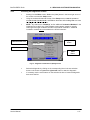
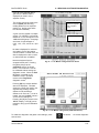
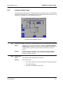
Accessing the Configuration Screen ...............................................1-25
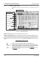
Instrument Configuration Screen - Initial Entry .................................1-26
Configuration Screen [X Box] Buttons .............................................1-27
QUICK REFERENCE CARD......................................................................................1-29
BACKGROUND INFORMATION .................................................................................... 2-1
2.1
INTRODUCTION...........................................................................................................2-1
2.2
SYSTEM CONTROL - MODSIG PCBA.......................................................................2-2
2.3
THERMISTOR PCBA (INPUT/OUTPUT)....................................................................2-6
2.4
3D 60 POWER SUPPLY ASSEMBLY.........................................................................2-8
2.5
DC POWER SUPPLY.................................................................................................2-10
2.6
CPU PCBA .................................................................................................................2-12
2.7
COMPACTFLASH ADAPTER PCBA........................................................................2-14
2.8
QUAD SERIAL INTERFAC E PCBA..........................................................................2-16
2.9
RACK CONTROLLER PCBA....................................................................................2-18
2.10 STEP-5 PCBA ............................................................................................................2-24
Service Manual
iii
TABLE OF CONTENTS
3
INSTALLATION PROCEDURES .................................................................................... 3-1
3.1
INTRODUCTION...........................................................................................................3-1
3.2
BACT/ALERT 3D 60 INSTALLATION PROCEDURES..............................................3-3
3.3
3.2.1
Verification of Site Requirements........................................................................3-3
3.2.2
Record Line Noise.............................................................................................3-3
3.2.3
Unpacking ........................................................................................................3-3
3.2.4
Repacking ........................................................................................................3-3
3.2.4.1
Verification of Contents....................................................................3-6
3.2.4.1.1
3D 60 Instrument Parts..................................................3-6
3.2.5
Set AC Power ...................................................................................................3-7
3.2.6
Instrument Placement ........................................................................................3-9
3.2.7
Instrument UPS.................................................................................................3-9
3.2.8
Power Up .......................................................................................................3-11
3.2.9
Instrument Configuration..................................................................................3-11
3.2.10
Temperature ...................................................................................................3-11
3.2.11
Error Check ....................................................................................................3-11
3.2.12
Modem Functional Test ...................................................................................3-12
3.2.13
Barcode Reader Functional Test ......................................................................3-13
3.2.14
UPS Functional Test (3D 60 Only, APC UPS 650).............................................3-13
3.2.15
Complete the Installation Checklist...................................................................3-13
RESTRAINT INSTALLATION....................................................................................3-14
3.3.1
Overview ........................................................................................................3-14
3.3.2
Procedure.......................................................................................................3-14
3.4
SOFTWARE INSTALLATION....................................................................................3-17
3.5
SWITCHING ON.........................................................................................................3-17
3.5.1
iv
BacT/ALERT® 3D 60
Initialization.....................................................................................................3-17
Service Manual
BacT/ALERT® 3D 60
4
TABLE OF CONTENTS
SERVICING......................................................................................................................... 4-1
4.1
INTRODUCTION...........................................................................................................4-1
4.2
SPECIFIC TOOLS AND REQUIRED...........................................................................4-3
4.3
POWER UP/DOWN PROCEDURES...........................................................................4-3
4.4
4.5
4.6
4.7
4.3.1
Introduction.......................................................................................................4-3
4.3.2
3D 60 Power Down ...........................................................................................4-3
4.3.3
3D 60 Power Up................................................................................................4-4
MB CONVERSION PROCEDURE...............................................................................4-5
4.4.1
Overview ..........................................................................................................4-5
4.4.2
Procedure.........................................................................................................4-5
DATA BACKUP/RESTORE PROCEDURES..............................................................4-9
4.5.1
BacT/ALERT 3D 60 - Data Backup Procedure ....................................................4-9
4.5.2
BacT/ALERT 3D 60 - Data Restore Procedure....................................................4-9
PREVENTIVE MAINTENAN CE .................................................................................4-11
4.6.1
Overview ........................................................................................................4-11
4.6.2
Perform Data Backup ......................................................................................4-11
4.6.3
Barcode Reader Functional Test ......................................................................4-11
4.6.4
Printer Maintenance ........................................................................................4-11
4.6.5
Temperature Verification..................................................................................4-11
4.6.6
Disabled Cell Check ........................................................................................4-11
4.6.7
+5 DC Voltage Verification...............................................................................4-11
4.6.8
UPS Test........................................................................................................4-11
4.6.9
“Door Open” Test ............................................................................................4-12
4.6.10
Completing the Preventive Maintenance Card ...................................................4-12
DIAGNOSTICS AND TROUBLESHOOTING............................................................4-13
4.7.1
Introduction.....................................................................................................4-13
4.7.2
Symptomatic Errors .........................................................................................4-13
Service Manual
v
TABLE OF CONTENTS
4.8
4.9
BacT/ALERT® 3D 60
SOFTWARE DIAGNOSTICS.....................................................................................4-15
4.8.1
Button Legend ................................................................................................4-15
4.8.2
Purpose of the Section ....................................................................................4-16
4.8.3
Special Equipment ..........................................................................................4-16
4.8.4
Accessing the Diagnostics Screens ..................................................................4-17
4.8.5
Diagnostic Screens Overview...........................................................................4-18
ALIGNMENTS AND CALIBRATIONS.......................................................................4-69
4.9.1
Overview ........................................................................................................4-69
4.9.2
System Power Supply......................................................................................4-69
4.9.3
Temperature ...................................................................................................4-69
4.9.4
Optics.............................................................................................................4-69
4.9.5
Rack – Single Cell Calibration ..........................................................................4-69
4.9.6
System Power Supply Check and Adjustments .................................................4-74
4.9.7
Door Micro Switch 1 & 2 Checks ......................................................................4-77
4.10 REMOVE AND REPLACE PROCEDURES ..............................................................4-79
vi
4.10.1
Introduction.....................................................................................................4-79
4.10.2
CPU PCBA Assembly (P/N 750-0070-01) .........................................................4-81
4.10.3
Quad Serial Interface PCBA (P/N 750-0066-01) ................................................4-89
4.10.4
CompactFlash Adapter PCBA (P/N 957-0004-356)............................................4-91
4.10.5
Software Installation and CompactFlash Memory Card Replacement .................4-94
4.10.6
ModSig PCBA (P/N 48300-1) (Order Spare P/N 48300-901) ..............................4-95
4.10.7
ModSig PCBA Fuses (P/N 870-0008-14, -17, -22) ........................................... 4-105
4.10.8
Step-5 PCBA (P/N 48301-1) (Order Spare P/N 48301-901).............................. 4-108
4.10.9
Step-5 Motor (P/N 48104-1) ........................................................................... 4-111
4.10.10
Outlet Thermistor PCBA (P/N 32300-1) .......................................................... 4-117
4.10.11
Inlet Thermistor PCBA (P/N 32300-1) ............................................................. 4-119
4.10.12
Zip™ Drive (P/N 895-0004-38) ....................................................................... 4-120
4.10.13
System Power Panel ..................................................................................... 4-124
Service Manual
BacT/ALERT® 3D 60
TABLE OF CONTENTS
4.10.14
Power Supply Transformer (P/N 851-0015-01) ................................................ 4-126
4.10.15
Power Supply MOV - Metal Oxide Varistor (P/N 43116-2) ................................ 4-128
4.10.16
Power Panel Solid State Relays (P/N 845-0018-01) ........................................ 4-130
4.10.17
DC Power Supply (P/N 852-0010-01) ............................................................. 4-132
4.10.18
Power Entry Module (PEM) Fuses (P/N 870-0008-14, -17, -24, -25) ................. 4-135
4.10.19
Fan (P/N 941-0009-07) .................................................................................. 4-138
4.10.20
Heater (P/N 847-0009-01).............................................................................. 4-140
4.10.21
Blower Assembly (P/N 48411-1)..................................................................... 4-142
4.10.22
Blower Motor Capacitor (P/N 601-0001-02)..................................................... 4-143
4.10.23
Digital Reference Thermometer (P/N 848-0003-01) ......................................... 4-148
4.10.24
Rack Assembly (P/N 43147-921, -922, -923)................................................... 4-149
4.10.25
Step-5 Drive Agitation Linkage Assembly (P/N 48418-1) .................................. 4-153
4.10.26
Gas Spring Assembly (P/N 926-0037-01)........................................................ 4-156
4.10.27
Magnetic Door Switches (P/N 841-0012-01).................................................... 4-158
4.10.28
Keyboard (P/N 957-0004-373) ....................................................................... 4-160
4.10.29
Barcode Scanner (P/N 957-0004-291) ............................................................ 4-161
4.10.30
Domestic 56K Fax Modem (P/N 957-0004-342) .............................................. 4-162
4.10.31
International Fax Modem (P/N 957-0004-364) ................................................. 4-163
4.10.32
APC Back-UPS Model 650 (Domestic Model) (P/N 957-0060-02) ..................... 4-164
4.10.33
APC UPS (International Model) (P/N 957-0060-03) ......................................... 4-169
4.11 POST SERVICE VALIDATION................................................................................4-175
4.11.1
Overview ...................................................................................................... 4-175
4.11.2
Required Materials ........................................................................................ 4-175
4.11.3
Procedures ................................................................................................... 4-175
Service Manual
vii
TABLE OF CONTENTS
BacT/ALERT® 3D 60
THIS PAGE
INTENTIONALLY
LEFT BLANK
viii
Service Manual
BacT/ALERT® 3D 60
0
0.1
TABLE OF CONTENTS
FRONT M ATTER
APPENDICES
Appendix A
GLOSSARY ....................................................................................... A.1
Appendix B
PARTS LIST ...................................................................................... B.1
Alphabetical Listing .................................................................................
Appendix C
DISINFECTION .................................................................................. C.1
Introduction ....................................................................................... C.1
Procedures........................................................................................ C.1
Spills ............................................................................................. C.1
Instrument Shipping........................................................................... C.1
Assembly Shipping ............................................................................ C.1
Appendix D
ERROR CODES ................................................................................. D.1
Appendix E
DIAGRAMS........................................................................................ E.1
INDEX
Service Manual
.................................................................................................. Index-1
ix
TABLE OF CONTENTS
BacT/ALERT® 3D 60
THIS PAGE
INTENTIONALLY
LEFT BLANK
x
Service Manual
BacT/ALERT® 3D 60
0.2
TABLE OF CONTENTS
LIST OF TABLES
Section 1
Table 1.2.1
Reference Data ........................................................................................1-2
Section 2
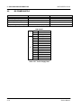
Table 2.2.1
Table 2.5.1
Audio Frequency Selection (JP 23 through JP26) .......................................2-4
Power Supply Data .................................................................................2-10
Section 3
Table 3.2.1
Table 3.2.2
3D 60 instrument Parts List .......................................................................3-6
Facility Power Rating and Conversion Chart ...............................................3-8
Table 3.2.3
Table 3.3.3
Table 3.3.4
Setup and Connections Table....................................................................3-9
Restraint Hardware.................................................................................3-14
Table of Equivalent Dimensions ...............................................................3-15
Section 4
Table 4.2.1
Table 4.7.1
Required Tools and Equipment ..................................................................4-3
Symptomatic Problems ...........................................................................4-13
Table 4.10.18
Facility Power Rating and Fuse Conversion Chart ................................... 4-135
Appendices
Table C 1.2
Service Manual
Disinfection Equipment............................................................................. C.1
xi
TABLE OF CONTENTS
BacT/ALERT® 3D 60
THIS PAGE
INTENTIONALLY
LEFT BLANK
xii
Service Manual
BacT/ALERT® 3D 60
0.3
TABLE OF CONTENTS
LIST OF ILLUSTRATIONS
CHAPTER 0 – FRONT MATTER
Fig. 1 - Text Box ......................................................................................................................................................................... xxi
Fig. 2 - USA 115 VAC Standard............................................................................................................................................ xxvi
Fig. 3 - European 230 VAC Standard.................................................................................................................................. xxvi
CHAPTER 1 – GENERAL INFORMATION
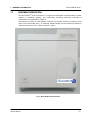
Fig. 4 - BacT/ALERT 3D 60 Instrument ................................................................................................................................1-3
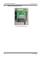
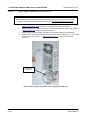
Fig. 5 - 3D 60 Power Panel Assembly ..................................................................................................................................1-4
Fig. 6 - Transformer..................................................................................................................................................................1-4
Fig. 7 - Blower & Heater...........................................................................................................................................................1-4
Fig. 8 - Step-5 Motor Assembly..............................................................................................................................................1-6
Fig. 9 - Fan Assembly ...............................................................................................................................................................1-6
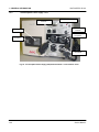
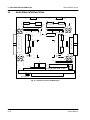
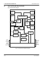
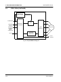
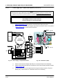
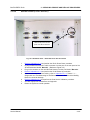
Fig. 10 - BacT/ALERT 3D 60 System Control (Rear View) w/Comm Ports.................................................................1-8
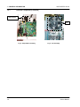
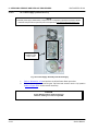
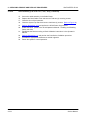
Fig. 11 - CPU PCBA ................................................................................................................................................................1-10
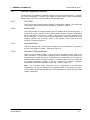
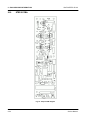
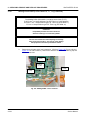
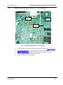
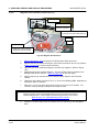
Fig. 12 - ModSig PCBA ..........................................................................................................................................................1-10
Fig. 13 - Quad Serial PCBA...................................................................................................................................................1-10
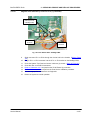
Fig. 14 - Thermistor PCBA....................................................................................................................................................1-10
Fig. 15 - CompactFlash Memory Disk................................................................................................................................1-12
Fig. 16 - CompactFlash Adapter PCBA.............................................................................................................................1-12
Fig. 17 - Step-5 PCBA.............................................................................................................................................................1-12
Fig. 18 - BacT 3D 60 Incubator Chamber..........................................................................................................................1-14
Fig. 19 - Rack Assembly........................................................................................................................................................1-14
Fig. 20 - Operator Display Monitor .....................................................................................................................................1-16
Fig. 21 - Barcode Scanner ....................................................................................................................................................1-16
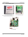
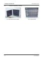
Fig. 22 - Keyboard...................................................................................................................................................................1-16
Fig. 23 - Zip Drive ....................................................................................................................................................................1-16
Fig. 24 - Uninterruptible Power Supply (UPS) Domestic Model – Front and Rear Views....................................1-20
Fig. 25 - Uninterruptible Power Supply (UPS) European Model – Front and Rear Views ...................................1-22
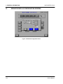
Fig. 26 - Instrument Configuration Screen.......................................................................................................................1-24
Fig. 27 - Main Screen..............................................................................................................................................................1-25
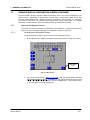
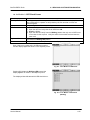
Fig. 28 - Setup Screen w/Field Engineer Password Activation ..................................................................................1-26
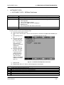
Fig. 29 - Instrument Configuration Screen.......................................................................................................................1-26
Fig. 30 - [X Box] Selection Checkbox ................................................................................................................................1-27
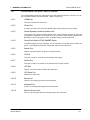
Fig. 31 - Quick Reference Card – Front Side ...................................................................................................................1-30
Fig. 32 - Quick Reference Card – Rear Side.....................................................................................................................1-31
Service Manual
xiii
TABLE OF CONTENTS
BacT/ALERT® 3D 60
CHAPTER 2 – BACKGROUND INFORMATION
Fig. 33
Fig. 34
Fig. 35
Fig. 36
Fig. 37
Fig. 38
Fig. 39
Fig. 40
Fig. 41
Fig. 42
Fig. 43
Fig. 44
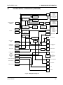
- ModSig PCBA Diagram ...........................................................................................................................................2-2
- ModSig Block Diagram............................................................................................................................................2-5
- Thermistor PCBA......................................................................................................................................................2-6
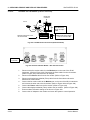
- Power Distribution Block Diagram.......................................................................................................................2-8
- CPU PCBA Diagram ...............................................................................................................................................2-12
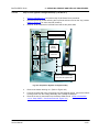
- CompactFlash Adapter PCBA.............................................................................................................................2-14
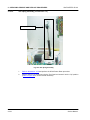
- Quad Serial Interface PCBA Diagram................................................................................................................2-16
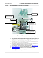
- Rack Controller PCBA Diagram..........................................................................................................................2-18
- Rack Controller PCBA Block Diagram..............................................................................................................2-20
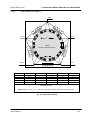
- Rack Address Concept..........................................................................................................................................2-22
- Step-5 PCBA Diagram............................................................................................................................................2-24
- Step-5 PCBA Block Diagram................................................................................................................................2-28
CHAPTER 3 – INSTALLATION PROCEDURES
Fig. 45
Fig. 46
Fig. 47
Fig. 48
Fig. 49
Fig. 50
Fig. 51
Fig. 52
Fig. 53
Fig. 54
Fig. 55
Fig. 56
Fig. 57
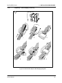
- 3D 60 Instrument Repacking Sequence .............................................................................................................3-4
- 3D 60 Instrument Repack – Web Strapping Diagrams ...................................................................................3-5
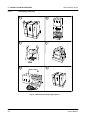
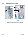
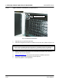
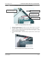
- Power Entry Module w. Fuse Holder Removed................................................................................................3-7
- Fuse Holder w/Fuse..................................................................................................................................................3-7
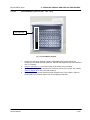
- PEM w/115 VAC Version .........................................................................................................................................3-8
- PEM w/230 VAC Version .........................................................................................................................................3-8
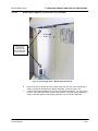
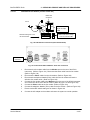
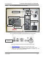
- Installation and Setup Diagram...........................................................................................................................3-10
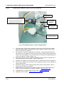
- Communications Panel Connection Diagram.................................................................................................3-12
- Modem Configuration & Dip Switch Settings Diagram ................................................................................3-12
- Countertop/Surface Mounting Diagram............................................................................................................3-12
- Mounting Surface Diagram ..................................................................................................................................3-15
- Mounting Surface (Drilling) Template ...............................................................................................................3-16
- Installation Checklist .............................................................................................................................................3-18
CHAPTER 4 - SERVICING
Fig. 58
Fig. 59
Fig. 60
Fig. 61
Fig. 62
Fig. 63
Fig. 64
Fig. 65
Fig. 66
Fig. 67
Fig. 68
Fig. 69
xiv
- 3D 60 Instrument – Power Switch ........................................................................................................................4-3
- Step-5 Motor PCBA Power Disconnect...............................................................................................................4-5
- MB Conversion – Lock Screw Removal .............................................................................................................4-6
- MB Conversion – Lock Screw Installation .........................................................................................................4-7
- Backup Management Button .................................................................................................................................4-9
- Cancel Button ............................................................................................................................................................4-9
- ModSig PCBA LED 55 and 56 location..............................................................................................................4-12
- Scanner Default Settings Barcode .....................................................................................................................4-13
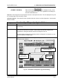
- Diagnostics Setup Screen Buttons ....................................................................................................................4-15
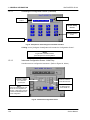
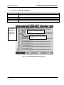
- Diagnostic Test Selection (Setup) Screen.......................................................................................................4-17
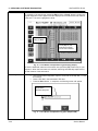
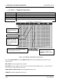
- 1.7 Inc Module/Flag Check ...................................................................................................................................4-18
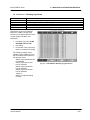
- 1.5 Inc Module 1/Temperature Log (Find Text String) ..................................................................................4-19
Service Manual
BacT/ALERT® 3D 60
TABLE OF CONTENTS
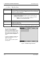
Fig. 70 - 1.5 Inc Module 1/Temperature Log (Text String Output)..............................................................................4-20
Fig. 71 - 1.5 Inc Module 1/Temperature Log (Save Output to Zip) .............................................................................4-20
Fig. 72 - 1.5 Inc Module 1/Temperature Log (Scroll/Anchor Buttons) ......................................................................4-21
Fig. 73 - 1.5 Inc Module 1/Temperature Log (Slide Bar) ...............................................................................................4-22
Fig. 74 - 1.1 Inc Module 1/Loopback Test Screen...........................................................................................................4-24
Fig. 75 - 1.2 Inc Module 1/Port Stats Test Screen...........................................................................................................4-25
Fig. 76 - 1.3 Inc Module 1/Message Stats Test Screen..................................................................................................4-26
Fig. 77 - 1.4 Inc Module 1/Message Log Test Screen....................................................................................................4-27
Fig. 78 - 1.5 Inc Module 1/Temperature Log Test Screen.............................................................................................4-28
Fig. 79 - 1.6 Inc Module 1/Reading Log Test Screen.....................................................................................................4-29
Fig. 80 - 1.7 Inc Module 1/Flag Check Screen.................................................................................................................4-30
Fig. 81 - 1.7 Inc Module 1/Flag Check Test Screen........................................................................................................4-31
Fig. 82 - 1.7 Inc Module 1/Flag Check (Calibration Screen..........................................................................................4-31
Fig. 83 - 1.8 Inc Module 1/Heater Screen..........................................................................................................................4-32
Fig. 84 - 1.9 Inc Module 1/LED Check ................................................................................................................................4-33
Fig. 85 - 1.9 Inc Module 1/LED Check (Walking) .............................................................................................................4-33
Fig. 86 - 7.1 Instrument Cntrl/ZIP Drive Test Screen.....................................................................................................4-35
Fig. 87 - 7.2 Instrument Cntrl/Barcode Loopback Test Screen...................................................................................4-36
Fig. 88 - 7.4 Instrument Cntrl/Power Event Log Screen ...............................................................................................4-39
Fig. 89 - 7.6 Instrument Cntrl/Software Test Screen – Scan........................................................................................4-62
Fig. 90 - 7.6 Instrument Cntrl/Software Test Screen – Misc........................................................................................4-66
Fig. 91 - Diagnostic Test Selection Screen – Flag Check ............................................................................................4-70
Fig. 92 - Incubator Flag Check – Cell Differences Screen...........................................................................................4-71
Fig. 93 - Flag Check – Cell Calibration Screen................................................................................................................4-72
Fig. 94 - System Power Panel and DC Supply.................................................................................................................4-74
Fig. 95 - Step-5 PCBA at Connector J4 .............................................................................................................................4-75
Fig. 96 - ModSig PCBA with +5 VDC Test Points ...........................................................................................................4-75
Fig. 97 - DC Power Supply....................................................................................................................................................4-75
Fig. 98 - Door Micro Switches and Magnets ....................................................................................................................4-77
Fig. 99 - Top Panel Screw Locations (Removal) .............................................................................................................4-81
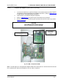
Fig. 100 - CPU PCBA w/Quad Serial PCBA plugged in.................................................................................................4-82
Fig. 101 - CPU PCBA - Screw Removal.............................................................................................................................4-83
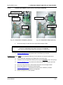
Fig. 102 - CPU PCBA – J27 and J7 Cable Routing .........................................................................................................4-84
Fig. 103 - Quad Serial PCBA Removed from CPU PCBA.............................................................................................4-85
Fig. 104 - CPU PCBA Cable Connections .........................................................................................................................4-86
Fig. 105 - WinSystems® CPU Connector Locations.......................................................................................................4-87
Fig. 106 - Quad Serial PCBA ................................................................................................................................................4-89
Fig. 107 - Quad Serial PCBA Cable Connections ...........................................................................................................4-90
Fig. 108 - EMC – CompactFlash PCBA..............................................................................................................................4-91
Fig. 109 - CompactFlash Adapter & ZIP Drive Installed ...............................................................................................4-92
Fig. 110 - CompactFlash Adapter w/WinSystems Computer......................................................................................4-92
Fig. 111 - CompactFlash Card (Memory Removal) ........................................................................................................4-93
Fig. 112 - CompactFlash Adapter (Removal)...................................................................................................................4-93
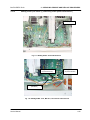
Fig. 113 - ModSig PCBA – Connector Location ..............................................................................................................4-95
Fig. 114 - ModSig PCBA........................................................................................................................................................4-96
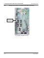
Fig. 115 - ModSig PCBA – Tie Wrap Removal.................................................................................................................4-97
Fig. 116 - ModSig PCBA – Bundled Cable Disconnection ...........................................................................................4-98
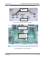
Fig. 117 - ModSig PCBA – JP19 Cable Removal.............................................................................................................4-99
Fig. 118 - ModSig PCBA – JP21, MS-JP11, JP12, &JP31 Cable Removal................................................................4-99
Fig. 119 - ModSig PCBA – MS-JP1 Cable Removal .................................................................................................... 4-100
Service Manual
xv
TABLE OF CONTENTS
Fig. 120
Fig. 121
Fig. 122
Fig. 123
Fig. 124
Fig. 125
Fig. 126
Fig. 127
Fig. 128
Fig. 129
Fig. 130
Fig. 131
Fig. 132
Fig. 133
Fig. 134
Fig. 135
Fig. 136
Fig. 137
Fig. 138
Fig. 139
Fig. 140
Fig. 141
Fig. 142
Fig. 143
Fig. 144
Fig. 145
Fig. 146
Fig. 147
Fig. 148
Fig. 149
Fig. 150
Fig. 151
Fig. 152
Fig. 153
Fig. 154
Fig. 155
Fig. 156
Fig. 157
Fig. 158
Fig. 159
Fig. 160
Fig. 161
Fig. 162
Fig. 163
Fig. 164
Fig. 165
Fig. 166
Fig. 167
Fig. 168
Fig. 169
xvi
BacT/ALERT® 3D 60
- ModSig – Rear Panel Screw Removal.......................................................................................................... 4-100
- ModSig PCBA – Mounting Screw Locations .............................................................................................. 4-101
- ModSig – Step-5 MCJ4 Connection .............................................................................................................. 4-102
- ModSig – Rear Panel Hex Nut & Knurled Nut Removal .......................................................................... 4-103
- ModSig PCBA – JP10, JP1 and Ground Cable .......................................................................................... 4-103
- ModSig PCBA Fuse Locations ....................................................................................................................... 4-105
- ModSig PCBA – Fuse Locations 1 ................................................................................................................ 4-106
- ModSig PCBA (Installed) - Fuse Locations 2 ............................................................................................. 4-107
- Step-5 PCBA Location...................................................................................................................................... 4-108
- Step-5 PCBA Connector and Wiring Locations ........................................................................................ 4-109
- Step-5 Motor Windings .................................................................................................................................... 4-111
- Step-5 Motor Removal – MCJ3 Disconnection .......................................................................................... 4-112
- Step-5 Motor Removal – Set-Screw Removal............................................................................................ 4-113
- Step-5 Motor Removal – Mounting Screw Removal................................................................................. 4-114
- Step-5 Motor Removal...................................................................................................................................... 4-114
- Step-5 Motor Removal – Reinstalling Mounting Screws........................................................................ 4-115
- Outlet Thermistor PCBA Removal ................................................................................................................ 4-117
- Inlet Thermistor PCBA Removal.................................................................................................................... 4-119
- Zip™ Drive Removal......................................................................................................................................... 4-120
- Zip Drive – Flash Adapter PCBA Removal................................................................................................. 4-120
- Zip Drive Screw Removal................................................................................................................................ 4-121
- Zip Drive Removal – Cutout Hole .................................................................................................................. 4-121
- Zip Drive Sled Removal (Side Screws)........................................................................................................ 4-122
- Zip Drive Sled Removal (Bottom Screws)................................................................................................... 4-122
- Zip Drive – Reconnecting IDE Cable and Power Connector.................................................................. 4-122
- Power Panel Assembly – Screw Removal.................................................................................................. 4-124
- Power Panel Assembly .................................................................................................................................... 4-125
- Power Panel Assembly – Installed ............................................................................................................... 4-125
- Power Supply Transformer – Power Supply Panel Removed............................................................... 4-126
- Power Panel with Transformer Installed..................................................................................................... 4-127
- Transformer – PEM Connections .................................................................................................................. 4-127
- Power Supply – Simplified Schematic ......................................................................................................... 4-128
- Term Board 1 (TB1)........................................................................................................................................... 4-128
- Power Panel Solid State Relay Layout ........................................................................................................ 4-130
- Power Supply Assembly w/DC Power Supply........................................................................................... 4-132
- DC Power Supply – J1 and J2 Disconnection ........................................................................................... 4-133
- Power Panel Assembly – DC Supply Screw Removal............................................................................. 4-134
- Power Entry Module w/Fuse Holder Removed.......................................................................................... 4-135
- Fuse Holder Fuse Installation ........................................................................................................................ 4-135
- PEM Fuse Removal w/ Screwdriver.............................................................................................................. 4-136
- PEM Fuse Holder Removal ............................................................................................................................. 4-136
- PEM Fuse Holder Pulled Out .......................................................................................................................... 4-136
- PEM w/115 VAC Version .................................................................................................................................. 4-137
- PEM w/230 VAC Version .................................................................................................................................. 4-137
- Fan – Inside View............................................................................................................................................... 4-138
- Fan Wiring Connections .................................................................................................................................. 4-138
- Heater Terminal Connectors .......................................................................................................................... 4-140
- Heater Removal.................................................................................................................................................. 4-141
- Blower Motor ...................................................................................................................................................... 4-142
- Blower Motor Capacitor ................................................................................................................................... 4-143
Service Manual
BacT/ALERT® 3D 60
Fig. 170
Fig. 171
Fig. 172
Fig. 173
Fig. 174
Fig. 175
Fig. 176
Fig. 177
Fig. 178
Fig. 179
Fig. 180
Fig. 181
Fig. 182
Fig. 183
Fig. 184
Fig. 185
Fig. 186
Fig. 187
Fig. 188
Fig. 189
Fig. 190
Fig. 191
Fig. 192
Fig. 193
Fig. 194
Fig. 195
Fig. 196
Fig. 197
Fig. 198
Fig. 199
Fig. 200
Fig. 201
Fig. 202
Fig. 203
Fig. 204
Fig. 205
Fig. 206
Fig. 207
Fig. 208
TABLE OF CONTENTS
- Power Supply Panel – BHP1 Connector...................................................................................................... 4-144
- Power Supply Panel – HBJ1/HBP1 Connector .......................................................................................... 4-144
- Power Supply Panel – Mounting Screw Removal..................................................................................... 4-145
- Blower Motor Capacitor – Boot and Clamp Removal.............................................................................. 4-146
- Reference Thermometer.................................................................................................................................. 4-148
- Rack Blocks Installed....................................................................................................................................... 4-149
- Rack Assembly w/Cable Cover Removed................................................................................................... 4-150
- Rack Cable Clamp Removed.......................................................................................................................... 4-150
- Rack Cable Disconnection.............................................................................................................................. 4-150
- Rack Assembly – Captive Screw Removal................................................................................................. 4-151
- Step-5 Drive Agitation Linkage Assembly .................................................................................................. 4-153
- Drive Linkage and Bushings Specs ............................................................................................................. 4-154
- Gas Spring Assembly....................................................................................................................................... 4-156
- Gas Spring Assembly Removal..................................................................................................................... 4-157
- Magnetic Door Switches.................................................................................................................................. 4-158
- Door Switch LEDs – ModSig PCBA.............................................................................................................. 4-159
- 3D 60 Rear Panel – Keyboard Port Connection ........................................................................................ 4-160
- 3D 60 Rear Panel – Barcode Scanner Port Connection .......................................................................... 4-161
- Fax Modem Port Connections (Domestic Model) ..................................................................................... 4-162
- Domestic 56K Fax Modem – Rear Port Connection................................................................................. 4-162
- Modem Port Connections (International Model) ....................................................................................... 4-163
- International 56K Fax Modem – Rear Port Connection........................................................................... 4-163
- APC UPS Domestic Model – BackUPS 650 (120V) (Front and Rear View)......................................... 4-164
- 3D 60 System Rear Communications Ports (UPS Cable Connection) ................................................ 4-164
- UPS Battery Connection Preparation .......................................................................................................... 4-165
- UPS Battery Cover Removal........................................................................................................................... 4-165
- Connecting UPS Battery Cable to Terminal............................................................................................... 4-166
- Domestic UPS with Battery Cables Connected......................................................................................... 4-166
- Domestic UPS with Battery Cover Secured............................................................................................... 4-167
- Domestic UPS Peripheral Connections ....................................................................................................... 4-167
- APC UPS International Model _BackUPS 650 (240V) (Front and Rear View).................................... 4-169
- 3D 60 System Rear Communications Ports (UPS Cable Connection) ................................................ 4-169
- International UPS Battery Connection Preparation ................................................................................. 4-170
- International UPS Battery Cover Removal ................................................................................................. 4-170
- Connecting UPS Battery Cable to Terminal............................................................................................... 4-171
- International UPS with Battery Cables Connected................................................................................... 4-171
- International UPS with Battery Cover Secured......................................................................................... 4-172
- International UPS Peripheral Connections ................................................................................................. 4-172
- Instrument Status Code 710................................................................................................................................D-9
Service Manual
xvii
TABLE OF CONTENTS
BacT/ALERT® 3D 60
THIS PAGE
INTENTIONALLY
LEFT BLANK
xviii
Service Manual
BacT/ALERT® 3D 60
0.4
TYPOGRAPHY AND GRAPHIC CONVENTIONS
TYPOGRAPHY AND GRAPHIC CONVENTIONS
The following is a comprehensive list of the typographical and graphic elements of this manual.
0.4
TYPOGRAPHY AND GRAPHIC CONVENTIONS..................................................... XIX
0.4.1
Bullets .............................................................................................................. xxi
0.4.2
Text Boxes ....................................................................................................... xxi
0.4.3
Bracketed Italics................................................................................................ xxi
0.4.4
Underlined Text................................................................................................. xxi
0.4.5
Bracketed Text................................................................................................. xxii
0.4.6
Text Within Quotation Marks ............................................................................. xxii
0.4.7
Italicized (Whether Bold or Not) Text ................................................................. xxii
Service Manual
xix
TYPOGRAPHY AND GRAPHICS CONVENTIONS
BacT/ALERT® 3D 60
THIS PAGE
INTENTIONALLY
LEFT BLANK
xx
Service Manual
BacT/ALERT® 3D 60
0.4.1
TYPOGRAPHY AND GRAPHIC CONVENTIONS
Bullets
Bullets are used to designate items in a list (•, -) or steps in a procedure (1, 2, etc)
0.4.2
Text Boxes
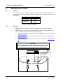
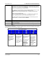
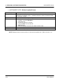
Important Steps
A text box can be a NOTE, CAUTION, WARNING or Image Note.
Fig. 1 - Text Box
Whenever text is contained within a box (Reference Figure 1) it identifies things that require
special attention. There are three different text boxes used within this manual:
0.4.3
•
NOTES: Used to clarify or explain a particular step. These text boxes are identified by
the word N
' OTE' (bold and all caps) centered at the top of the box and normal text
following.
•
CAUTIONS: Used to identify actions that could cause DAMAGE to the instrument or
test equipment. These text boxes are identified by the word 'CAUTION' (bold and all
caps) centered at the top of the box and bold text following.
•
WARNINGS: Used to identify actions that could result in INJURY or DEATH to
personnel performing the procedure (or close by). These text boxes are identified by the
word 'WARNING' centered at the top of the box and bold capitalized text following.
•
IMAGE NOTES: Used to explain steps of a process, identify component parts,
suggestions and other steps related to the functionality of the instrument. The text
boxes are not identified with any special markings. Generally they will surround photos
and drawings and will explain processes, parts or other related information.
Brac keted Ita lic s
Brackets around Italics text, [Italics Text], identifies items to be clicked on the display screen.
(I.E.: Press [On Line] to continue).
0.4.4
Underli ned Te xt
Underlined text identifies words, groups, or characters that are to be typed on the keyboard.
(I.E.: Type <Y><E><S> to continue, or Press <ALT> + <CTRL> + <DEL> to reboot.)
Service Manual
xxi
TYPOGRAPHY AND GRAPHIC CONVENTIONS
0.4
0.4.5
BacT/ALERT® 3D 60
T YPOGRAPHY AND GRAPHIC CONVENT IONS (CONT INUED)
Brac keted Text
Single text within brackets identifies single keys to be pressed on the keyboard. (I.E.: Press
<Esc> to exit the system.)
0.4.6
Text W ithin Quotation Marks
Whenever text is displayed within quotation marks, it usually means that this a displayed
message on the screen. (I.E.: After previous step is complete, the system will display 'Press
Any Key to Continue'.)
0.4.7
Ita lic iz ed (W hether Bold or Not) Text
Whenever text is in Italics (or Bold Italics), it provides for emphasis, or identifies key words
or concepts. Whenever this format is seen, it is an important operative part of the meaning of
the text or added notation. Bold Italics designate STRONG emphasis and is not to be
ignored or taken lightly.
xxii
Service Manual
BacT/ALERT® 3D 60
0.5
SAFETY SUMMARY
SAFETY SUMMARY
The following is a comprehensive list of the safety issues outlined in this chapter.
0.5
SAFETY SUMMARY ................................................................................................. XXIII
0.5.1
General Information to Follow ........................................................................... xxv
0.5.2
Electrical Warnings ........................................................................................... xxv
0.5.3
Electrical Grounding .........................................................................................xxvi
0.5.4
Fuse Replacement Warning ..............................................................................xxvi
0.5.5
Hazardous Voltages .........................................................................................xxvi
0.5.6
Cleaning Agents...............................................................................................xxvi
0.5.7
Health Risks ................................................................................................... xxvii
0.5.8
ESD Precautions ............................................................................................. xxvii
0.5.9
Moving Parts................................................................................................... xxvii
0.5.10
Heating Element ............................................................................................. xxvii
Service Manual
xxiii
SAFETY SUMMARY
BacT/ALERT® 3D 60
THIS PAGE
INTENTIONALLY
LEFT BLANK
xxiv
Service Manual
BacT/ALERT® 3D 60
0.5.1
SAFETY SUMMARY
General Inform ation to Fol low
This manual contains WARNINGS, CAUTIONS and NOTES, specific instructions and other
information that must be followed and observed at all times. This will help ensure the safe
handling and operation of the instrument.
0.5.2
•
NOTE: Clarifies or explains a particular step or procedure. A note box is identified with
the word NOTE in bold text and the explanatory body text is not bolded.
•
CAUTION: Warns of a risk of DAMAGING equipment or components. A caution may be
identified with the word CAUTION and its explanatory body text is bolded.
•
WARNING: Identifies a process step that may cause injury or DEATH to personnel. A
warning may be identified with the word WARNING and its explanatory body text is
bolded in all caps.
Elec tric al W arnings
The BacT/ALERT 3D 60 has been designed and tested IAW IEC Publication 61010-1: Safety
Requirements for Electrical Equipment for Measurement, Control, and Laboratory Use, UL
3101-1, CAN/CSA C22.2 No. 1010.1-92 and has been supplied in safe condition. A CB
Certificate and Construction File have been established for the instrument.
1.
Before applying power, ensure that the Power Entry Module (PEM) is properly
configured for the specific facility power voltage. Also ensure that the fuse(s) is (are)
installed and of proper rating value. (See Subsection 3.2.5 – Set AC Power)
2.
Any interruption of the protective conductor inside or outside of the instrument or
disconnection of the protective earth terminal is likely to make the instrument dangerous
to lab personnel and other users.
3.
Any adjustment, maintenance or repair of the opened instrument while under voltage
should be avoided. If power to the instrument is necessary, repair or maintenance shall
be carried out only by a trained and qualified individual who is aware of the hazard(s)
involved with the task. In addition, a second individual will be nearby to render aid, if
necessary.
4.
Make sure that only fuses with the required current rating and of the specified type are
used for a replacement. The use of makeshift fuses or the short -circuiting of any fuse
holder is extremely dangerous and prohibited. (See Subsection 3.2.5 – Set AC Power)
5.
Whenever it is likely that a BacT/ALERT 3D 60 has been impaired, it will be made
inoperative by powering it down and disconnecting the power cord. If there is evidence
of moisture within the instrument, turn the facility power off at the circuit breaker junction
box before removing the power cable. The instrument is likely to be impaired if it:
6.
Service Manual
•
Shows visible damage
•
Fails to perform an intended operation
•
Has been subjected to storage or operation under unfavorable conditions. (i.e.,
above 80% humidity, dusty environment, prolonged storage. (Refer to Section 12, Table 1.2.1, for tolerances.
•
Has been subjected to severe transport stresses.
If any of the above conditions occur, a qualified service technician must check the
instrument out prior to use.
xxv
SAFETY SUMMARY
0.5
0.5.3
BacT/ALERT® 3D 60
SAFET Y SUMM ARY (CONT INUED)
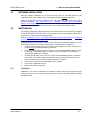
Elec tric al Grounding
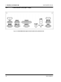
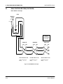
An electrical ground is required and must be in place for this instrument.
Before installing the instrument, ensure that a grounded wall receptacle is available for each
unit. It must be plugged into a mating grounding type wall receptacle in accordance with
National Electrical Codes (US Domestic) and/or applicable local codes and ordinances
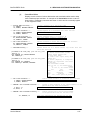
(domestic or international) for this type of installation. (Reference Figure 2, below)
WARNING
UNDER NO CIRCUMSTANCES IS THE GROUND PRONG TO BE REMOVED. IF THE
GROUND PRONG, THE PLUG, OR THE CORD HAVE ANY PHYSICAL DAMAGE, THE CORD
IS TO BE REPLACED. IT IS EXTREMELY HAZARDOUS TO OPERATE THIS (OR ANY)
INSTRUMENT WITH A MISSING GROUND PRONG OR A FAULTY CABLE IN PLACE.
Fig. 2 - USA 115 VAC Standard
0.5.4
Fig. 3 - European 230 VAC Standard
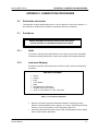
Fus e Replac em ent W arning
®
There are no user-serviceable fuses in the BacT/ALERT 3D 60. Only trained and qualified
service technicians are to replace any fuse within the instrument. The only exception to fuse
installation will be during the initial installation of the unit. At the time of installation, the
customer does install PEM fuses according to steps outlined in the Installation section of the
BacT/ALERT 3D 60 Operator’s Manual.
0.5.5
Haz ardous Volta ges
DC voltages used within the instrument are low voltage and low current. They do not pose
any immediate hazard to technicians. There is, however, facility power of either 115 VAC or
230 VAC within or near the power supply assembly, which could pose an electrical hazard if
proper precautions are not observed. Note: All voltages are potentially hazardous under the
proper circumstances.
0.5.6
Cleaning Agents
Follow manufactures’ instructions and MSDS (Material Safety Data Sheets) information to
prevent any possible hazards that may be present when using cleaning agents (or other
chemicals).
xxvi
Service Manual
BacT/ALERT® 3D 60
0.5
SAFETY SUMMARY
SAFET Y SUMM ARY (CONT INUED)
0.5.7
Health Ris ks
Specimens and inoculated culture bottles are to be assumed as though they are capable of
transmitting infectious agents. Handling of any bottles or specimens must be done with the
utmost care. Spills must be cleaned as soon as possible, using the disinfection procedures
®
outlined in the BacT/ALERT 3D 60 Operator’s Manual and Appendix C of this manual.
0.5.8
ESD Prec autions
®
The BacT/ALERT 3D 60 contains several electrostatic sensitive devices within the modules.
Proper ESD precautions, in addition to the use of a grounding strap, are imperative whenever
working on or near any ESD components.
0.5.9
Mo ving Parts
There are moving parts within the left side of the instrument’s chassis. At times, personnel
may be exposed to the Agitation Drive Arm, Motor Offset Round and other internal moving
parts. Care must be taken to avoid exposure of clothing, hands, fingers, arms, etc. Prior to
performing maintenance procedures around moving parts, it is advised that loose clothing
(i.e. ties, long sleeves, etc.) be secured.
0.5.10
Heatin g Elem ent
The instrument contains a heater to perform the incubation process. The heater may remain
hot for a period of time after the unit is first shut down for maintenance. To prevent burns,
avoid contact with the heater until it is known that it is cool enough to touch.
Service Manual
xxvii
SAFETY SUMMARY
BacT/ALERT® 3D 60
THIS PAGE
INTENTIONALLY
LEFT BLANK
xxviii
Service Manual
BacT/ALERT® 3D 60
CHAPTER 1 – GENERAL INFORMATION
CHAPTER 1
GENERAL INFORMATION
CHAPTER 1 – GENERAL INFORMATION
BacT/ALERT® 3D 60
THIS PAGE
INTENTIONALLY
LEFT BLANK
Service Manual
BacT/ALERT® 3D 60
1
1 – GENERAL INFORMATION
GENERAL INFORM AT ION
This chapter describes the theory of operation and the general characteristics of the equipment.
1.1
INTRODUCTION
The following is a comprehensive list of the general descriptions of instrument components,
operational reference data, subassemblies and operator display configurations.
1
GENERAL INFORMATION .............................................................................................. 1-1
1.1
INTRODUCTION...........................................................................................................1-1
1.2
REFERENCE DATA.....................................................................................................1-2
1.3
EQUIPMENT DESCRIPTION.......................................................................................1-3
1.4
ASSEMBLY DESCRIPTIONS......................................................................................1-4
1.5
OPERATOR DISPLAY CONFIGURATION SCREENS............................................1-24
1.6
QUICK REFERENCE CARD......................................................................................1-29
1-1
1 – GENERAL INFORMATION
1.2
BacT/ALERT® 3D 60
REFERENCE DATA
This chart represents the environmental conditions for use, including the physical, functional and
technical characteristics of the BacT/ALERT 3D 60 instrument.
Electrical Power
Service Required
Power Consumed
In Watts
Heat Dissipated
In BTU/hr
Equipment Characteristics
Width
Height
Depth
Weight
Environmental Characteristics
Operating Temperature Range
100/120/220/240VAC @ 50/60Hz
120VAC: 480W Max
240VAC: 480W Max
1639 BTU/Hr. Max
23.1 in. / 58.7cm
23.9 in./ 60.7cm
19.9 in. / 60.5 cm
94 lbs. / 42.5Kg
10°C - 30°C (50°F - 86°F)
Storage Temperature
Range
17°C - 57°C (0°F - 135°F)
Operating and Storage
Humidity Range
10% - 90% RH (non-condensing)
Operating and Storage
Altitude
No restrictions
Table 1.2.1 – Combination Module Reference Data
1-2
Service Manual
1 – GENERAL INFORMATION
1.3
BacT/ALERT® 3D 60
EQUIPMENT DESCRIPTION
®
The BacT/ALERT 3D 60 instrument is a compact and automated microbial detection system
capable of incubating, agitating, and continuously monitoring specimens suspected of
contamination from bacteremia / fungemia.
The instrument consists of a WinSystems CPU and one 60-bottle chamber consisting of three
racks of 20 culture bottles each. An externally attached display monitor permits the operator to
control and monitor the racks. (Refer to Figure 4, below)
Fig. 4 - BacT/ALERT 3D 60 Instrument
Service Manual
1-3
1 – GENERAL INFORMATION
1.4
BacT/ALERT® 3D 60
ASSEMBLY DESCRIPTIONS
The following paragraphs indicate the composition of the system, (i.e., the equipment, hardware,
software and consumables required for it to operate.
1.4.1
Elec tric al Com ponents
Fan
Relays
DC Power
Supply
TB1
Transformer
Fig. 5 - 3D 60 Power Panel Assembly
Fig. 6 - Transformer
Blower
Heater
Fig. 7 - Blower & Heater
1-4
Service Manual
1 – GENERAL INFORMATION
1.4.1
1.4.1.1
BacT/ALERT® 3D 60
Elec tric al Com ponents (Continued)
Power Panel Assembly
®
The BacT/ALERT 3D 60 instrument uses a standard BTA cabinet power supply. The
Power Panel Assembly provides the AC and DC power supply voltages that are used
within the 3D 60. With the use of relays, this will also shut down incubation processes
when instructed to do so by the ModSig PCBA. The power supply provides the four
separate DC voltages (+ 5V and ±12V) used throughout the instrument. (Refer to Figure
5)
1.4.1.2
Transformer Assembly
This is a transformer to isolate the instrument from facility power and is installed on the
System Power Panel. (Refer to Figure 6)
1.4.1.3
Heater
The heater provides the necessary heat for the incubation process of bottle cultures.
(Refer to Figure 7)
1.4.1.4
Blower
For the incubation process, the blower circulates heat (produced by the heater)
throughout the 3D 60 instrument. (Refer to Figure 7)
Service Manual
1-5
1 – GENERAL INFORMATION
1.4.1
BacT/ALERT® 3D 60
Elec tric al Com ponents (Continued)
Step-5 Motor
Fan
Fig. 8 - Step-5 Motor Assembly
1-6
Fig. 9 - Fan Assembly
Service Manual
1 – GENERAL INFORMATION
1.4.1
1.4.1.5
BacT/ALERT® 3D 60
Elec tric al Com ponents (Continued)
Step-5 Motor Assembly
This Step-5 Motor (Figure 8) provides agitation to the racks, unless the incubation
chamber has been converted to MB and the motor has been disconnected to bypass
this process. (Refer to Subsection 4.4.2, Figures 59, 60 and 61 for MB Conversion)
1.4.1.6
Fan
A fan circulates air over the electronic components within the Electronics Compartment
to help prevent overheating. This fan may also be called the E-Fan. (Refer to Figure 9)
1.4.1.7
Quick Reference Card
This card identifies specific error codes and outlines instructions regarding system
operation. Refer to Section 1.6, Figure 31 - Front Side and Figure 32 - Rear Side)
Service Manual
1-7
1 – GENERAL INFORMATION
1.4.2
BacT/ALERT® 3D 60
Comm unic ations Ports (Input / Output)
Fig. 10 - BacT/ALERT 3D 60 System Control (Rear View) w/Comm Ports
1-8
Service Manual
1 – GENERAL INFORMATION
1.4.2
BacT/ALERT® 3D 60
Comm unic ations Ports (Input / Output) (Continued)
The communications ports are input/output ports that peripheral devices connect to on the
rear of the BacT/ALERT 3D 60 instrument. (Refer to Figure 10)
1.4.2.1
COMM Port
This port is reserved for future use.
1.4.2.2
Printer Port
A printer connects to this port via a parallel cable and produces hard copy reports.
1.4.2.3
Internal Speaker w/external Speaker Jack
The system has a remote speaker feature with a 5mm external mini-jack to drive two
remote stereo speakers from a distance of up to 450 feet (see Remote Speakers P/N
880-0002-01 and 02, along with 100-ft. of speaker wiring, P/N 957-0004-350.
1.4.2.4
Power Entry Module (PEM) / ON-OFF Switch
The PEM contains the fuse protection for the unit when connected to main facility AC
power. The PEM also houses the main power switch for the instrument.
1.4.2.5
Modem Port
Used to connect the BacT 3D 60 to an external modem.
1.4.2.6
LIS Port
This port is used for connection to the facility’s LIS system.
1.4.2.7
Monitor Port
This port is used for connection to an external VGA or SVGA monitor.
1.4.2.8
UPS Port
Used to connect an external UPS to the instrument.
1.4.2.9
UPS Serial Port
Reserved for future use.
1.4.2.10
Mouse Port
Used for connecting the mouse to the instrument.
1.4.2.11
Keyboard Port
A port for connecting the keyboard to the instrument.
1.4.2.12
Barcode Scanner Port
Port for connecting the barcode-scanning wand to the instrument.
Service Manual
1-9
1 – GENERAL INFORMATION
1.4.3
Elec tronic Com ponents
CPU Board
ModSig Board
Fig. 11 - CPU PCBA
Fig. 12 - ModSig PCBA
Quad Serial Board
Thermistor Board
Fig. 13 - Quad Serial PCBA
1-10
BacT/ALERT® 3D 60
Fig. 14 - Thermistor PCBA
Service Manual
1 – GENERAL INFORMATION
1.4.3
BacT/ALERT® 3D 60
Elec tronic Com ponents (Continued)
The Electronics Compartment is situated in the top part of the 3D 60 instrument. It contains
®
the internal WinSystems computer (CPU PCBA and Quad Serial PCBA), CompactFlash
Adapter PCBA, Zip™ Drive, Step-5 PCBA and the ModSig PCBA.
1.4.3.1
CPU PCBA
The CPU is a 586 processor with an operating clock speed of 133MHz. This is the heart
of the system and controls all system operations. (Reference Figure 11)
1.4.3.2
ModSig PCBA
This board provides an interface between the CPU PCBA and the rest of the system. It
serves as a module controller for the system PCBAs, monitors incubation temperature
and the external port devices (i.e., modem, scanner, LIS, etc.) that are attached to the
3D 60 instrument. It also monitors several independent system tasks such as DC
voltages, switches, the frequency output of the speaker, power reset and other
functions. (Reference Figure 12)
1.4.3.3
Quad Serial PCBA
This board provides the communications interface from the WinSystems computer to
the rest of the system (incubator). (Reference Figure 13)
1.4.3.4
Thermistor PCBA (Input/Output)
There are two Thermistor PCBAs. One is the Input Thermistor and the other is the
Output Thermistor. The Input Sensor measures the air temperature from the warmer air
circulated by the heater fan and the Output Sensor the temperature of the cooler air
measured after Incubator Chamber circulation. A reading is taken from each sensor and
the average temperature reading of the two comprise the Incubator Chamber’s
temperature used by the temperature control logic. (Refer to Figure 14)
Note: The Input and Output Thermistors are not components of the Electronics
Compartment, yet they are described as integrated PCBAs of the electronic system.
The thermistors boards are installed in the lower compartment of the left and right inside
chassis, respectively.
Service Manual
1-11
1 – GENERAL INFORMATION
1.4.3
BacT/ALERT® 3D 60
Elec tronic Com ponents (Continued)
Fig. 15 - CompactFlash Memory Disk
Fig. 16 - CompactFlash Adapter PCBA
NOTE: Flash memory disk above may not necessarily reflect the actual
memory disk or size being used in the 3D 60 instrument.
Fig. 17 - Step-5 PCBA
1-12
Service Manual
1 – GENERAL INFORMATION
1.4.3
1.4.3.5
BacT/ALERT® 3D 60
Elec tronic Com ponents (Continued)
CompactFlash Memory Disk
This CompactFlash disk is a removable mass storage device installed on the
CompactFlash Adapter PCBA. It is a device about the size of a matchbook and weighs
about one-half ounce. Since it is a solid-state device utilizing flash memory, it contains
no moving parts and requires no battery for data retention. The CompactFlash Disk is
compatible with IDE/ATAPI standards and serves as the C: drive in the BacT/ALERT 3D
60 application, where it holds the operating program, bottle records, system
configurations, event log files and miscellaneous other information needed for
BacT/ALERT operation. (Refer to Figure 15)
1.4.3.6
CompactFlash Adapter PCBA
The PCM-CFLASH PCBA (Reference Figure 16) is a PC/104 compatible adapter
module, designed specifically to adapt CompactFlash memory disks for use in
embedded systems such as the BacT/ALERT 3D 60. The adapter provides for
master/slave selection and a visual drive status indicator. The CompactFlash Adapter
PCBA is installed on the top cover of BacT/ALERT 3D 60 system.
1.4.3.7
Step-5 PCBA
The Step-5 controller board (Reference Figure 17) is designed to drive a five-phase
stepper motor at the speed of 60 revolutions per minute. The board operates with input
voltages of +5V and +12V, drives the stepper motor directly, and provi des starting and
stopping functions based on inputs received from the ModSig PCBA.
Service Manual
1-13
1 – GENERAL INFORMATION
1.4.3
Elec tronic Com ponents (Continued)
Fig. 18 - BacT 3D 60 Incubator Chamber
1-14
BacT/ALERT® 3D 60
Fig. 19 - Rack Assembly
Service Manual
1 – GENERAL INFORMATION
1.4.3
1.4.3.8
BacT/ALERT® 3D 60
Elec tronic Com ponents (Continued)
Incubator Chamber Components
The Incubation Chamber (Reference Figure 18) contains three specimen racks, relays,
power supply, ModSig PCBA, rack controller PCBAs, heater and blower. As viewed by
the operator, the bottles are loaded into the front of the 3D 60 instrument.
1.4.3.8.1
Rack
Each rack contains 20 bottle cells. Unless the instrument is designated as an MB
unit, the racks are continuously rocked (to provide agitation for the specimen
bottles). Also, three fascia plates identify the bottle locations and are not
interchangeable between replacement racks. (Refer to Figure 19)
1.4.3.8.2
Cell
There are 60 cells per instrument, with cells identified as 1 through 20 in the first
(top) rack, 21 through 40 in the middle rack and 41 through 60 in the bottom rack.
1.4.3.8.3
Cell Flag
The cell flag serves as a clip securing the bottles into their cells. The cell flag is
also a key component in bottle detection and cell diagnostics.
1.4.3.8.4
Cell Indicator Lamp
A lamp is located next to each cell and provides feedback to the operator.
Depending on the function selected by the operator, illuminated lamps identify the
positions of positive or negative bottles, cells that can be loaded, and so on. A
flashing indicator lamp indicates an operator error.
Service Manual
1-15
1 – GENERAL INFORMATION
1.4.4
BacT/ALERT® 3D 60
Inp ut / Output Devic es
Fig. 20 - Operator Display Monitor
Note:
Fig. 21 - Barcode Scanner
The figure above shows a flat panel monitor and
may not represent the model or type of monitor
actually shipped with the 3D 60 instrument.
Fig. 22 - Keyboard
Fig. 23 - Zip Drive
NOTE
The photos of output devices shown above may not necessarily reflect the models being installed.
1-16
Service Manual
1 – GENERAL INFORMATION
1.4.4
1.4.4.1
BacT/ALERT® 3D 60
Inp ut / Output Devic es (Continued)
Operator Display Monitor
The display monitor is a standard VGA monitor used for displaying diagnostic and
module setup information. (Reference Figure 20)
1.4.4.2
Barcode Scanner
The QuickScan™ 6000 Barcode Scanner scans bottle labels, identifying the bottles
whenever loading or unloading. (Reference Figure 21)
1.4.4.3
Keyboard
This is a standard-sized 101-key keyboard. It is used as an alternative input device to
the barcode scanner or mouse. (Reference Figure 22)
1.4.4.4
Zip Drive
This drive provides an internal resource for loading new operating system software and
performing system data backup. (Reference Figure 23)
Service Manual
1-17
1 – GENERAL INFORMATION
BacT/ALERT® 3D 60
THIS PAGE
INTENTIONALLY’
LEFT BLANK
1-18
Service Manual
1 – GENERAL INFORMATION
1.4.4
1.4.4.5
BacT/ALERT® 3D 60
Inp ut / Output Devic es (Continued)
56K FAX Modem (Domestic)
The fax modem serves as an interface to the BacT 3D 60 instrument for remote access.
The remote user is able to download and upload information, including seeing what is on
the display-screen that the local operator views. The Technical Support Center is able
to perform remote diagnostics and other troubleshooting of the instrument.
The modem interfaces the 3D 60 instrument through a connection to the Modem port on
the rear of the unit. Digital signals are converted to tones by the modem for sending to
the telephone system through the telephone jack connection and to a remote modem at
on the receiving end. Conversely, tones from the remote modem are converted to digital
signals and sent to the instrument through the Modem port. Power for the modem is
supplied by a wall-mounted power supply that supplies low voltage required by the
modem. The wall-mounted power supply plugs directly into a standard electrical outlet.
1.4.4.6
56K Fax Modem (International)
The international fax modem differs slightly from the domestic version, by having CE
markings and is shipped with a 220V AC adapter. It also has two additional DIPswitch
settings (9 & 10). (See Subsection 3.2.12, Figure 53, for instructions on International
Fax Modem DIP switch settings.
The fax modem serves as an interface to the BacT 3D 60 instrument for remote access.
The remote user is able to download and upload information, including seeing what is on
the display-screen that the local operator views. The Technical Support Center is able
to perform remote diagnostics and other troubleshooting of the instrument.
The modem interfaces the instrument through a connection to the Modem port on the
rear of the unit. Digital signals are converted to tones by the modem for sending to the
telephone system through the telephone jack connection and to a remote modem at on
the receiving end. Conversely, tones from the remote modem are converted to digital
signals and sent to the instrument through the Modem port. Power for the modem is
supplied by a wall-mounted power supply that supplies low voltage required by the
modem. The wall-mounted power supply plugs directly into a standard electrical outlet.
Service Manual
1-19
1 – GENERAL INFORMATION
1.4.5
BacT/ALERT® 3D 60
Uninterru ptible Power Supply “ UPS”
Telephone Surge
Protection
On/Off Switch
Computer Interface Port
Overload
Protector
120V Backup
Receptacles
Test Switch
Accessory Surge
Receptacles
Fig. 24 - Uninterruptible Power Supply (UPS) Domestic Model – Front and Rear Views
1-20
Service Manual
1 – GENERAL INFORMATION
1.4.5
BacT/ALERT® 3D 60
Uninterru ptible Power Supply “ UPS” (Continued)
Refer to Figure 24 for the following component descriptions of the domestic UPS.
1.4.5.1
On/Off Switch
Turns the UPS and BacT/ALERT 3D 60 unit ON and OFF from the UPS.
1.4.5.2
UPS Comm Port (Computer Interface Port)
The UPS Computer Interface Port is a standard 9-pin port used to connect a cable that
monitors communications between the UPS and the 3D 60 Instrument. (The port
connection is shown as Computer Interface Port in Figure 24)
1.4.5.3
Overload Reset Switch
The Overload Switch is a reset switch (breaker) allowing for UPS reset following a power
surge or uncommon UPS shutdown. The overload is rated 120VAC, 12 Amp (Max) at
50/60Hz.
1.4.5.4
Test (Check Battery/Alarm Disable) Switch
By pressing the top of Test (toggle) switch, the UPS battery may be checked. The UPS
powers the loads from the battery. If the UPS emits the battery exhaustion alarm, the
battery is weak and requires extended charge or replacement.
1.4.5.5
120V Backup Receptacles
These 120V AC receptacles are used when devices connected to the UPS require full
battery backup to allow proper shutdown of the equipment. A device that may require
such battery backup might be the Display Monitor, since it is required to shut down the
3D 60 instrument in a “facility power-fail” situation.
1.4.5.6
Accessory Surge Receptacles
These 120V receptacles are used when devices connected to the UPS do not require
battery backup but may require voltage surge protection. A device that may require
surge protection but not battery backup might be a Parallel Printer.
1.4.5.7
AC Power Cord
The AC Power Cord is a standard three-pronged AC (grounded) cord.
Service Manual
1-21
1 – GENERAL INFORMATION
1.4.5
BacT/ALERT® 3D 60
Uninterru ptible Power Supply “ UPS” (Continued)
Computer Interface
Port
On/Off Switch
Overload
Protector
Accessory Surge
Receptacle
Test Switch
240V Backup
Receptacles
Fig. 25 - Uninterruptible Power Supply (UPS) European Model – Front and Rear Views
1-22
Service Manual
1 – GENERAL INFORMATION
1.4.5
BacT/ALERT® 3D 60
Uninterru ptible Power Supply “ UPS” (Continued)
The European UPS model is very similar to the US domestic model. The voltage rating,
power cord and fuse ratings, however, are for the European power conversions. (Refer to
Figure 25 for International/European UPS components)
Service Manual
1-23
1 – GENERAL INFORMATION
1.5
BacT/ALERT® 3D 60
OPERATOR DISPLAY CONFIGURATI ON SCREENS
Fig. 26 - Instrument Configuration Screen
1-24
Service Manual
1 – GENERAL INFORMATION
1.5
BacT/ALERT® 3D 60
OPERAT OR DISPLAY CONFIGURAT ION SCREENS (CONT INUED)
The BacT/ALERT 3D 60’s Operator’s Manual describes most of the screens displayed on the
display monitor. Specifically, it describes the screens used to: load/unload bottles, set the date
and time, enable/disable cells, calibrate incubation temperature, perform single cell calibration,
set maximum test times, set audible alarm options and change passwords. For detailed
information on these screens, refer to the BacT/ALERT 3D 60 Operator’s Manual.
1.5.1
Ins trum ent Configurati on Sc reen
This screen is primarily used when an instrument is being installed. It allows the field service
engineer to enter information regarding rack installation. (Refer to Figure 26)
1.5.1.1
Accessing the Configuration Screen
Perform the following steps to gain access to the Configuration Screen:
1.
At the “Main Screen”, click on the [Next Screen] button (Refer to Figure 27, below)
Next Screen
button
Fig. 27 - Main Screen
2.
Service Manual
Once at the “Setup Screen” (Refer to Figure 28), enter the Field Engineer password
<4><3><4><3><2><1><2><1>, by clicking on the number buttons at the top of the
screen. After entering the password, click on the [Key] button. (See “Setup Screen”
on the next page for Screen Diagnostics).
1-25
1 – GENERAL INFORMATION
1.5.1.1
BacT/ALERT® 3D 60
Accessing the Configuration Screen (Continued)
Key button
Password Key
buttons
System Setup
Screen
Configure Screen
button
Previous Screen button
Fig. 28 - Setup Screen w/Field Engineer Password Activation
Clicking on the [Configure Screen] button will access the “Configuration Screen”.
NOTE
To get back to the Main Screen,
press the [Previous Screen] button.
1.5.1.2
Instrument Configuration Screen - Initial Entry
Use this screen to configure the instrument. (Refer to Figure 29, below.)
Determines whether
a period or comma,
this is used as a
decimal point.
Designates which
racks are installed in
the 3D 60 instrument.
When checked, this
box designates the
unit as an MB unit.
NOTE
Checks for enable/disabled racks
as well as rack configuration is
required. “Hash marks” exist with
or without enable/disabled racks
or rack configuration.
Fig. 29 - Instrument Configuration Screen
1-26
Service Manual
1 – GENERAL INFORMATION
1.5.1.3
BacT/ALERT® 3D 60
Configuration Screen [X Box] Buttons
Several configuration options are represented by a graphical element called an [X Box]
button. As shown in Figure 30 below, an [X Box] button can appear with or without an
“X” in the box. The “X” determines the active selection. Clicking inside the box with the
mouse switches the box to the opposite state.
Fig. 30 - [X Box] Selection Checkbox
Service Manual
1-27
1 – GENERAL INFORMATION
BacT/ALERT® 3D 60
THIS PAGE
INTENTIONALLY
LEFT BLANK
1-28
Service Manual
1 – GENERAL INFORMATION
1.6
BacT/ALERT® 3D 60
QUICK REFERENCE CARD
The Quick Reference Card (Figure 31 and Figure 32 on the following pages, Front and Rear
Sides, respectively) is simply that…a quick reference. The card contains references to errors and
®
fault codes that may appear on the BacT/ALERT 3D 60 during operation. The card’s purpose is
to aid the operator in determining what may have caused a particular problem. It does not
contain corrective action measures. For more information, refer to Appendix D – Error Codes of
®
this manual and the BacT/ALERT 3D 60 Operator’s Manual for possible solutions.
Service Manual
1-29
1 – GENERAL INFORMATION
1.6
BacT/ALERT® 3D 60
QUICK REFERENCE CARD (CONT INUED)
Card P/N 955-0500-03 Rev A
OPERATION ERROR CODES
Refer to Operator Manual for detailed error description and troubleshooting instructions.
Code
Description
Code
Description
901
CORRUPTED BOTTLE RECORD HAS BEEN SELEC TED
902
REQUIRED DATA MISSING
910
INVALID CELL LOAD
940
BOTTLE DETAIL NOT FOUND
911
INVALID CELL UNLOAD
941
BOTTLE ID ENTERED MATCHES THAT OF A BOTTLE THAT IS
912
INVALID CELL RELOAD
913
BOTTLE ID JUST SCANNED MATCHES THAT OF A
932
BOTTLE ID SCANNED MATCHES THAT OF A PREVIOUSLY UNLOADED
BOTTLE
CURRENTLY LOADED IN A DIFFERENT CELL
CURRENTLY LOADED BOTTLE
942
BOTTLE TYPE CHANGE REQUIRES DIFFERENT ALGORITHM
943
IDENTIFIED BOTTLE CHANGED TO ANONYMOUS
921
BARCODE SCAN NOT ALLOWED IN THIS MODE
944
MANUAL UNLOAD OF ANONYMOUS BOTTLE
923
INVALID BARCODE ENTRY
945
BOTTLE ID ENTERED MATCHES THAT OF A PREVIOUSLY UNLOADED
930
INCORRECT OR UNEXPECTED BARCODE SCANNED
BOTTLE
AFTER UNLOADING A BOTTLE
931
960
DUPLICATE ENTRIES
961
INVALID BLANK FIELD
DETECTION ALGORITHM HAS BEEN CHANGED
SEE REVERSE FOR INSTRUMENT FAULT CODES
Fig. 31 - Quick Reference Card - Front Side
Detailed error descriptions and troubleshooting instructions may also be found in Appendix D of this manual.
1-30
Service Manual
1 – GENERAL INFORMATION
1.6
BacT/ALERT® 3D 60
QUICK REFERENCE CARD (CONT INUED)
INSTRUMENT FAULT AND STATUS CODES
Refer to Operator Manual for detailed error description and troubleshooting instructions.
Code
Description
Code
Description
1
POWER FAULT IN INCUBATION MODULE
60
CELL FAILED QC
2
COMMUNICATION LOST WITH INCUBATION MODULE
62
ERRONEOUS CELL LOAD STATUS REPORTED
3
INCUBATION MODULE TEMPERATURE IS TOO HIGH
71
INVALID TIME STAMP
4
INCUBATION MODULE TEMPERATURE IS TOO LOW
72
INVALID CALCULATION DATA
5
INCORRECT INCUBATION MODULE CONNECTION
73
INVALID METHOD DATA
10
CONTROLLER MODULE POWER FAULT
74
ALGORITHM CHANGE
11
INSUFFICIENT CHARGE IN UPS
75
BOTTLE DATA CORRUPTED
12
LIS COMMUNICATION FAULT
77
READING POLYNOMIAL CHANGE
19
SOFTWARE EXCEPTION
78
INCOMPLETE TEST DATA
20
DRAWER OPEN FOR TOO LONG
79
BOTTLE RELOADED VIA WRONG CONTROLLER
21
DRAWER AGITATION FAILURE
99
BOTTLE LOADED IN A NON-OPERATIONAL CELL
22
UNEXPECTED DRAWER AGITATION
39
RACK TEMPERATURE FAULT
41-47
RACK(S) NOT RESPONDING
51-57
RACK HARDWARE FAILURE
710
INCUBATION MODULE TEMPORARILY UNAVAILABLE WHILE POWER UP
INITIALIZATION TAKES PLACE
800
PRINTER FAULT
810
BACKUP FAILED
SEE REVERSE FOR OPERATOR ERROR CODES
Fig. 32 - Quick Reference Card - Rear Side
Detailed error descriptions and troubleshooting instructions may also be found in Appendix D of this manual.
Service Manual
1-31
1 – GENERAL INFORMATION
BacT/ALERT® 3D 60
THIS PAGE
INTENTIONALLY
LEFT BLANK
1-32
Service Manual
BacT/ALERT® 3D 60
CHAPTER 2 – BACKGROUND INFORMATION
CHAPTER 2
BACKGROUND INFORMATION
Service Manual
CHAPTER 2 – BACKGROUND INFORMATION
BacT/ALERT® 3D 60
THIS PAGE
INTENTIONALLY
LEFT BLANK
Service Manual
BacT/ALERT® 3D 60
2
2 – BACKGROUND INFORMATION
BACKGROUND INFORM ATION
2.1
INTRODUCTION
The following is a comprehensive list of items outlined in this chapter. Included are the system
PCBAs and the function of each, as well as the Incubation Chamber and Power Supply.
2
BACKGROUND INFORMATION .................................................................................... 2-1
2.1
INTRODUCTION...........................................................................................................2-1
2.2
SYSTEM CONTROL - MODSIG PCBA.......................................................................2-2
2.3
THERMISTOR PCBA (INPUT/OUTPUT)....................................................................2-6
2.4
3D 60 POWER SUPPLY ASSEMBLY.........................................................................2-8
2.5
DC POWER SUPPLY.................................................................................................2-10
2.6
CPU PCBA .................................................................................................................2-12
2.7
COMPACTFLASH ADAPTER PCBA........................................................................2-14
2.8
QUAD SERIAL INTERFAC E PCBA..........................................................................2-16
2.9
RACK CONTROLLER PCBA....................................................................................2-18
2.10 STEP-5 PCBA ............................................................................................................2-24
Service Manual
2-1
2 – BACKGROUND INFORM ATION
2.2
BacT/ALERT® 3D 60
SYSTEM CONTROL - MODSI G PCBA
Fig. 33 - ModSig PCBA Diagram
2-2
Service Manual
BacT/ALERT® 3D 60
2.2
2 – BACKGROUND INFORMATION
SYST EM CONT ROL - M ODSIG PCBA (CONT INUED)
The MODSIG PCBA provides interfaces to the 3D 60 Instrument Controller section, the Step-5
board, external peripherals and the Rack PCBA’s. It uses a 68HC11 microprocessor with
firmware stored in the EPROM. The microprocessor uses an external 16 MHz crystal for its
clock. 32Kbytes of EPROM and 32Kbytes of static RAM are external, with no internal ROM.
There are 512 bytes of EEPROM and 1024 bytes of RAM, both of which are internal.
A 4.5-volt reference is on the PCBA for A/D reference and a 2.5-volt reference for temperature
control. Power-fail circuitry detects if the +5VDC is out of tolerance. LED’s on the board show E
Fan ON, Power-Enable ON, Blower ON, Heater ON, Agitation ON, +5V ON for ModSig, +5V ON
for Step-5 PCBA, +5V ON for Racks, Door Switches Closed, six status indicators and RS-485
transmit and receive indicators.
Temperature sensors on the board are used for E-Fan control and to report electronics overtemperature conditions. External input and output temperature sensors are used by PID control
firmware on the microprocessor for incubation temperature control and are connected to JP1.
Heater, blower and fan ON/OFF time control signals connect through a connector at JP2. A 12bit, 8-channel A to D converter integrated circuit does conversion from analog values to digital
values for microprocessor use.
The front door has two separate interlock switches. These connect to the MODSIG PCBA
through JP11 and JP12. One switch, which the firmware cannot override, functions as a safety
interlock that disables the heater and blower if the door should open. The second switch is for
logic functions and redundancy. Both switches are monitored by the firmware and by the Step-5
agitation motor control firmware.
An instrument ID thumbwheel switch, normally set to 1, is available if there should be a need to
separately identify a 3D 60 at a customer’s site.
A Piezo buzzer is provided as an audible alarm. A remote speaker system may be used, by
connecting to J1. The keyboard connects to JP16. A barcode reader connects to P1 and a
mouse connects to P2. A parallel port printer connects to P4. A LIS system is interfaces via P8
and a modem via P9.
JP13, JP15, JP17, JP18 and JP19 connect to the Instrument Controller CPU in the 3D 60. JP29
and JP30 are used for transferring serial data signals from the Quad Serial PCBA. The Serial
UPS connector at P7 is for future use. The UPS is controlled through the connector at P5 and
must be connected for proper system operation. The VGA display monitor is connected at P6.
Five -volt power is connected to the board at JP31 and is supplied to the Zip Drive and the
CompactFlash PCBA through JP21. Control and data signals for the racks are supplied through
JP10.
Jumpers on the ModSig PCBA control the audio frequencies supplied to the remote speakers.
The remote speakers control volume. Volume jumpers on the board are for future use only. See
Table 2.2.1 for remote speaker audio frequency selections.
Service Manual
2-3
2 – BACKGROUND INFORM ATION
2.2
BacT/ALERT® 3D 60
SYST EM CONT ROL - M ODSIG PCBA (CONT INUED)
FREQUENCY
JP23
JP24
JP25
JP26
600 Hz
800 Hz
1 KHz
1.5 KHz
3 KHz
In
In
In
In
Out
In
In
In
Out
Out
In
In
Out
Out
Out
In
Out
Out
Out
Out
Table 2.2.1 - Audio Frequency Selection (JP23 through JP26)
2-4
Service Manual
BacT/ALERT® 3D 60
2.2
2 – BACKGROUND INFORMATION
SYST EM CONT ROL - M ODSIG PCBA (CONT INUED)
TO:
•
J2
•
•
Step-5 PCBA
Door Interlock
Switches
+5 Power
Agitate ON
32KB RAM
FROM: Step- 5 PCBA
•
Error Signal
68HC11
32KB RAM
Heater Inlet/Outlet
Temperature
Sensors
JP1
Drivers
A/D
Converter
2 Temp
Sensors
JP2
Instrument
ID Switch
JP11
Door Interlock
Switches
JP12
Undervoltage/
Overvoltage
Detector
JP10
JP16
•
•
•
•
•
Blower ON
Heater ON
Agitate ON
E Fan ON
Power En ON
To & From
Drawer A (#1)
Rack PCBA
•
DC Power
•
Rack ID
•
Event Request
•
RS-485
•
Drawer ID
PS2 Keyboard
Piezo Buzzer
Oscillator
Driver
P1
Barcode Port
RS-232 from
CPU
JP13
P2
Mouse Port
Keyboard,
RS-232, Printer
From CPU
JP15
P4
Parallel Printer
Port
Parallel I/O
To/From CPU
JP17
P5
UPS Control
Parallel I/O
To/From CPU
JP18
P6
VGA Monitor
RS-232,
Rs-485 from
Quad Serial
PCBA
RS-232 from
Quad Serial PCBA
Driver
JP29
JP21
+5V
CompactFlash
Zip Drive
JP30
+5VDC Power In
JP31
Video from CPU
JP19
J1
Remote Speaker
P7
Serial UPS
P8
LIS
P9
Modem
Fig. 34 - ModSig Block Diagram
Service Manual
2-5
2 – BACKGROUND INFORM ATION
2.3
BacT/ALERT® 3D 60
THERMISTOR PCBA (INPUT/OUTPUT)
J3
J2
J1
Fig. 35 - Thermistor PCBA
2-6
Service Manual
BacT/ALERT® 3D 60
2.3
2 – BACKGROUND INFORMATION
T HERM ISTOR PCBA (INPUT /OUTPUT ) (CONT INUED)
The Thermistor board uses an Analog device AD592BN temperature transducer to produce a
current flow proportional to temperature. The voltage source is +9VDC. The temperature
transducer has a nominal flow of 298.2µa+ 25ºC.
There are two Thermistors PCBAs in the 3D 60 instrument. The Input and Output Thermistors
measure input and output air temperature, respectively. The Input and Output temperature
readings are averaged together to comprise the Incubation Chamber’s temperature used by the
temperature control logic.
Service Manual
2-7
2 – BACKGROUND INFORM ATION
2.4
BacT/ALERT® 3D 60
3D 60 POWER SUPPLY ASSEMBLY
Power Distribution Block Diagram
Facility
Power
UPS
Power
Entry
Module
Isolation
Transformer
MOV
Blower
TB 1
Heater
Elec.
Comp.
Fan
Common Logic Ground Return 3
CPU PCBA
+5 VDC
DC Power
Supply
-12 VDC
E Fan
Relay
Heater
Relays
+12 VDC
Blower
Relays
Power
Enable
ModSig PCBA
Power Panel
+5VDC
GND
Step Five PCBA
Agitation Motor
Fig. 36 - Power Distribution Block Diagram
2-8
Service Manual
BacT/ALERT® 3D 60
2.4
2 – BACKGROUND INFORMATION
3D 60 POWER SUPPLY ASSEM BLY (CONT INUED)
Input power for the 3D 60 (Refer to Figure 36) is either 115 VAC or 220 VAC. The installation
technician sets the proper voltage selection at the Power Entry Module (PEM). The circuitry is
protected by one 6.3A “time-delay” 250 VAC fuse (120 VAC version) or two 5A “time-delay” 250
VAC fuses (240 VAC version). AC voltage is coupled across the isolation transformer thus
insulating the instrument from facility power for circuit protection including a 120:120VAC or a
240:120VAC (step-down) voltage ratio.
Input power is routed to a metal oxide varistor (MOV) that’s mounted between terminals 2B & 3B
of TB1. The varistor provides inline surge protection for the internal circuitry of the system. From
TB1, power is routed to the fan, DC power supply and all “power-enable” relays.
The DC power supply provides the necessary DC voltages on J2 for various sub-units throughout
the 3D 60 Instrument. There are three separate voltages; ± 12VDC and + 5VDC, with a common
DC return providing a logic ground. In addition, the DC power supply provides a “Power Fail”
signal that is routed to the ModSig PCBA.
Service Manual
2-9
2 – BACKGROUND INFORM ATION
2.5
BacT/ALERT® 3D 60
DC POWER SUPPLY
Parameter
Condition
Limits
Input Voltage
85 - 264 VAC
Input Frequency Range
47 - 440 Hz
Input Surge Current
Cold Start, 110 VAC/220 VAC
17 A maximum/ 34A maximum
Output Voltage Adjustability
+5.1 VDC output (Supply Only)
± 3%
PIN CHART
J1
P1
P2
P3
AC Ground
AC Neutral
AC Hot
J2
P1
P2
P3
P4
P5
P6
P7
P8
P9
P10
P11
P12
P13
+ 5.1 VDC
+ 5.1 VDC
+ 5.1 VDC
Return
Return
Return
Return
+ 12 VDC
+ 12 VDC
PFD
- 12 VDC
- 5 VDC
Table 2.5.1 - Power Supply Data
2-10
Service Manual
BacT/ALERT® 3D 60
2.5
2 – BACKGROUND INFORMATION
DC POWER SUPPLY (CONT INUED)
The BacT/ALERT 3D 60’s power supply is a quad output switcher intended for small to mediumsized digital systems. These power supplies also contain built-in over-voltage protection and a
“power fail detect” signal.
Universal input voltage allows these supplies to be powered in any country of the world without
changing any jumpers or individual switch settings. The unit is capable of supplying the high
peak currents necessary to start disk drives and peripheral devices. An integral filter reduces
line-conducted noise below FCC and VDE limit B.
The over-voltage protection circuits are designed to activate at 6.25 VDC (± 0.75 VDC) for 5 VDC
output. The power supply has a “Power Fail Detection” circuit that produces a “power fail
detection” (PFD) output. The PFD signal occurs within milliseconds following an abnormal AC
line condition. The delay between the abnormal AC line condition and the PFD output varies
depending on AC line variation and power supply load.
If this condition is met, the PFD signal will go to a low state within approximately 3ms. Once the
output returns to the +4.75 VDC the PFD signal will return to a high state in 50ms to 200ms.
Refer to Table 2.5.1, on the previous page, for Power Supply data and output pin locations.
Service Manual
2-11
2-12
U27
U24
C11
+
D6 D5D4 D3
U21
J36
+ +
J32
C9
U20
LS1
J31
J30
J21
U19
J23
J26
J22
U18
U25
U17
J25
J24
J21
T1
J20
J16
J15
J14
J13
J5
U11
U3
J12
U2
U1
U22
J17
U15
Y1
U5
U14
J27
J41
J28
U8
R16
U9
J18
U10
J11
J10
Y2
C8
J9
J8
C6
J6
R4
+
C1
R2
R3
R1
C5
R5
C7
U6
U4
U7
J2
J4
C3
J33
T2
C2
C10
J37
J35
J34
U29
U28
U23
J38
C4
D2
D1
J3
J1
2.6
SIM1
J40
J39
2 – BACKGROUND INFORM ATION
BacT/ALERT® 3D 60
CPU PCBA
LITHIUM
KEEPER
LTC-3PN
II
U16
Y3
U26
Fig. 37 - CPU PCBA Diagram
Service Manual
BacT/ALERT® 3D 60
2.6
2 – BACKGROUND INFORMATION
CPU PCBA (CONT INUED)
The CPU PCBA (Reference Figure 37) is an “off-the-shelf” internally mounted WinSystems
computer that combines a 586 (or higher) CPU with Video, Floppy, IDE, Serial and Digital I/O.
®
The chipset provides the core logic that makes the board PC/AT software compatible. It includes
the DRAM controller, bus interface, integrated peripheral controllers (8237 DMA, 82C54 timer,
82C59 PIC, RTC, KYBD controller and CMOS memory) and an internal PCI bus for high-speed
operation.
Up to 32 MB of memory can be populated on board with a 72-pin SIMM. The BIOS can detect
and automatically support either Fast Page or EDO memory modules. Seven DMA channels are
supported, with Channel 2 dedicated to the floppy disk controller. The LPT is jumper selectable
for ECP operation. The other DMA channels are wired to the PC/104 connector. An onboard
256KB x 16 DRAM provides 512KB of video memory.
Service Manual
2-13
2 – BACKGROUND INFORM ATION
2.7
BacT/ALERT® 3D 60
COMPACTFLASH ADAPTER PCBA
Fig. 38 - CompactFlash Adapter PCBA
2-14
Service Manual
BacT/ALERT® 3D 60
2.7
2 – BACKGROUND INFORMATION
COM PACT FLASH AD APT ER PCBA (CONT INUED)
A CompactFlash Adapter PCBA (with CompactFlash Memory Disk™ installed) is mounted near
®
the WinSystems motherboard. It is connected by a flat ribbon cable to the motherboard’s IDE
port. (Refer to Figure 38 or Subsection 4.10.4, Figures 108-112)
®
The Flash-Memory Disk contains the operating system, BacT/ALERT 3D 60’s software,
instrument configurations, operator settings, layout of the instrument pictorial, along with the
bottle record data.
Service Manual
2-15
2 – BACKGROUND INFORM ATION
2.8
BacT/ALERT® 3D 60
QUAD SERIAL INTERFACE PCBA
1
U1
1
U3
U2
J1
U4
J2
R37
C2
R36
C9
R19
C10
R16
R7
R8
R18
R20
J6
U10
1
Com 1 and Com 2, J6
C15
J4
J5
R35
1
1
U14
U12
R38
Com 3 and Com 4, J3
C6
C4
U6
U13
C13
C12
U7
U9
J3
R15
R12
U8
U11
R10
R4
R17
RP2
C11
R22 R21 C8
R14
R5
R6
RP1
R13
R11
R3
C14
C7 C5
U5
R2
R9
R1
C3
C1
1
C19
C22
C21
R29
R26
R31
C24
U15
R27
C20
R25
C23
R33
C18
R24
C25
R34
C17
R23
U16
R32
J7
1
J10
1
J9
1
Copyright 1995 Made in USA
1
C27
+
WinSystems
DC
J11
J8
®
32
U18
1
RP3
RP4
U17
R30
C26
R28
J12
PCM-COM4A Rev. B
Fig. 39 - Quad Serial Interface PCBA Diagram
2-16
Service Manual
BacT/ALERT® 3D 60
2.8
2 – BACKGROUND INFORMATION
QUAD SERIAL INT ERFACE PCBA (CONT INUED)
The Quad Serial Interface (Com4) board (Reference Figure 39) is a daughter board that plugs
®
into the PC/104 bus on the WinSystems motherboard.
There are four ports on the board. Com 1 is configured as a RS-485 port. Com 2 3 and 4 are
configured as RS-232 ports. Com 1 and Com 2 are located on connector J6, while Com 3 and
Com 4 are located on connector J3. All communications ports are software supported and
operate at a 9.6K Baud data rate.
The Quad Serial is a four-channel serial (INS8250 compatible) P/C 104 module that is based on
the 16C554 UART. It is ideally suited for applications running DOS programs or languages that
require exact register compatible hardware for program execution. Each of the channels
supports RS-232, with optional RS -485 and RS-422 electrical levels to interface with a wide
variety of serial communications devices.
The Quad Serial PCBA is I/O mapped. Each channel requires eight port addresses and each is
independently decoded within the I/O map. The interrupt status register also requires one I/O
port. The addresses are decoded in the PAL and are jumper-selectable, with eight different I/O
maps. The Com4 card is a 16-bit stack-through card that supports 8-bit data transfers only.
Service Manual
2-17
2 – BACKGROUND INFORM ATION
2.9
BacT/ALERT® 3D 60
RACK CONTROLLER PCBA
Fig. 40 - Rack Controller PCBA Diagram
2-18
Service Manual
BacT/ALERT® 3D 60
2.9
2 – BACKGROUND INFORMATION
RACK CONT ROLLER PCBA (CONT INUED)
The Rack Controller PCBA (Refer to Figure 40), using EPROM-stored software, controls the
excitation LEDs. The LED light illuminates and reflects on the bottle sensors, creating emitted
measurable values at the photo detectors. The Rack Controller digitizes each cell’s photodetector output for reading by the ModSig’s Control Module and for bottle presence detection.
Cell indicator LEDs are controlled for operator information. Status and data are communicated
through an RS-485 cable from the Rack Controller to the ModSig board. The microprocessor
software also monitors the bottle rack rocking motion with a “Hall-Effect” sensor. In addition, the
software normalizes illumination readings with cell and temperature calibration factors. Address
®
lines from the ModSig are used to confirm that the 3D 60’s WinSystems CPU board is
addressing the correct Rack Controller thus eliminating the need for switches on each Rack
Controller. Calibration values are stored onboard the Rack Controller PCBA in a non-volatile
RAM (NVRAM). The Rack Controller PCBA is located in the rear portion of the rack channel of
the Incubation Chamber. A fully implemented Incubation Chamber will have three Rack
Controller PCBAs.
The microprocessor is the Motorola 68HC11 and the same used on the ModSig PCBA. This
microprocessor has separate 16-bit address and 8-bit data lines defined. This eliminates the
need of having external address and data multiplexing for the external 32KB of RAM and 32KB of
EPROM included on the PCBA.
The clock speed of the 68HC11 is set at 16 MHz by an external crystal. Internally, the
microprocessor contains 512 bytes of EPROM, 1024 bytes of RAM, and no ROM. External
memory for the microprocessor is on the Rack Controller PCBA. A 16-bit free running counter,
driven by a programmable prescaler and other divider chains, provides for a wide range of
internal timing periods for software use. Included is a watchdog timer.
The Rack Controller PCBA uses 32KB of static RAM in a surface mount package. The software
for most dynamic storage uses this memory. The Rack Controller uses 32KB of EPROM for
program storage. Jumpers are included to allow the installation of larger memory, in the event
that the 27C256 microprocessor becomes obsolete. Memory parts with less than 90ns access
are required.
There are two 20-pin connector positions on the board. Power (+5 volts for each board) is
supplied through a cable from the ModSig to the JP2 connector. The other connector, JP1, is
cabled to JP2 of the next rack. No other power is required. A fuse on the ModSig protects the
set of three Rack Controllers in the Incubator Chamber.
The +5 volt input voltage produces two reference voltages. A +4.5V reference is provided to the
A-D converter. A +2.5V reference is provided for the Rack temperature operational amplifiers as
well as an accurate current control of the exciter LED’s current by an operational amplifier.
Each cell has one exciter LED. Each of these LEDs is driven by an output from a 74ACT374
driver.
One indicator LED is provided for each bottle holder or cell. Each of the LEDs is driven by an
output from a 74ACT374 driver. In addition, there are four “status” LEDs for general purpose and
are explained in the firmware.
Service Manual
2-19
2 – BACKGROUND INFORM ATION
2.9
BacT/ALERT® 3D 60
RACK CONT ROLLER PCBA (CONT INUED)
Rack Controller Block Diagram
Agitation
Sensor
32 KB
RAM
Cell
Sensors OP
Amps 1-20
32 KB
RAM
68HC11 Microprocessor
w/internal RAM and EPROM
Analog
Multiplexer
Cell
Exciters
1-20
Drivers
Constant
Current
Control
Rack
Temperature
Reference
Voltage
Cell
Indicators
1-20
12-Bit
A-D
Converter
Drawer ID
RS-485
RCVR/XMTR
Drawer ID
Rack ID Output
Event Request
To/From
ModSig or
previous Rack
Controller
To/From Next
Rack Controller:
+5 V OUT
RS-485
Rack ID
Drawer ID
Event Request
Rack ID OUT
+5V IN
RS-485
Rack ID
Event Request
Rack ID OUT
Fig. 41 - Rack Controller PCBA Block Diagram
2-20
Service Manual
BacT/ALERT® 3D 60
2.9
2 – BACKGROUND INFORMATION
RACK CONT ROLLER PCBA (CONT INUED)
Each cell has an individual external sensor. The sensor outputs are multiplexed to cascaded
operational amplifiers that drive the analog input of an A-D Converter. The cell sensor readings
are sent, on request, to the instrument. The Rack Controller firmware detects bottle presence
from these photodiode sensors as well.
Circuitry is provided to develop the analog signals to the A-D Converter for the two temperature
sensors on the Rack PCBA. These sensors are part of the calibration factors for the bottle cells.
The agitation sensor is a “Hall-Effect” sensor. The sensor detects bottle rack motion for a change
in magnetic flux from a rare-earth magnet as the rack is agitated. Each board has a sensor;
however, only one position in each drawer is utilized for monitoring.
The Event Request signal is a common open drain signal driven by the ModSig PCBA and all
Rack Controller PCBAs. The ModSig, Rack Controller and WinSystems CPU board can also
read the signal. Its purpose is similar to an interrupt signal; it's to notify the WinSystems CPU
board that an event such as a bottle removal has occurred. For the ModSig, this signal is both an
output to the WinSystems CPU board and an input from the Rack Controller. When the Event
Request is pulled low, the Drawer ID low signal used by the Rack Controllers is disabled. The
Rack Controller drives the Drawer ID lines to indicate which Rack Controller(s) activated the
Event Request line. The Rack Control firmware reads the Event Request line before and after
reconfirming its address, to ensure address lines are not in use.
With only one of four lines low for each drawer, the Rack Controllers can determine which drawer
they are in for each address identification for WinSystems CPU board commands. When the
Event Request is low, this is disabled; allowing the same lines to be used by the Rack Controllers
to identify which ones activated the Event Request. The driving circuitry and input circuitry is
provided on the Rack Controller. Firmware on the ModSig aids the WinSystems CPU board in
selecting which Rack Controllers read status, thus expediting bottle detection state changes.
The ModSig makes only one of the three Rack ID lines low for each rack, and then polling this
line within the Rack PCBAs, the Rack Controllers can determine their address without having
individual address switches. (Refer to Figure 42 on the next page)
Four outputs from one of the 74ACT374-exciter LED drivers serve as the output drivers for the
Rack ID Out signals, through open-drain inverters.
The communication between the modules is over RS-485 full-duplex circuitry. The necessary
conversion between RS-485 differential signals and single-ended CMOS compatible serial
signals, for use by the software, is contained on the Rack Controller. The actual RS-485 signals
connect to all Rack Controllers through a connector on the ModSig PCBA.
Service Manual
2-21
2 – BACKGROUND INFORM ATION
2.9
BacT/ALERT® 3D 60
RACK CONT ROLLER PCBA (CONT INUED)
Rack Address Concept
JP10
ModSig
PCBA
+ 5V
+ 5V
16
17
18
Polling line
connects via
JP2 on each
Rack PCBA
RACK #1
RACK #2
RACK #3
JP2
JP2
JP2
JP1
JP1
JP1
16
16
16
16
16
16
17
17
17
17
17
17
18
18
18
18
18
18
Rack #1 Address Code
Rack #2 Address Code
Rack #3 Address Code
Input pins 18-17-16
Binary
1- 1 - 0
Input pins 18-17-16
Binary
1- 0- 1
Input pins 18-17-16
Binary
0- 1- 1
Fig. 42 - Rack Address Concept
2-22
Service Manual
BacT/ALERT® 3D 60
2.9
2 – BACKGROUND INFORMATION
RACK CONT ROLLER PCBA (CONT INUED)
A 12-bit A-D Converter is provided to convert the rack temperature sensor’s analog signals to the
digital signals used by the Rack Controller software. The same A-D Converter is used for
converting cell sensor analog signals into digital signals.
Using the +2.5V reference voltage, the resistor voltage dividers, an operational amplifier and a
MOSFET controls the current for the exciter LEDs. Only one exciter LED is activated at any one
time.
Service Manual
2-23
2 – BACKGROUND INFORM ATION
2.10
BacT/ALERT® 3D 60
STEP-5 PCBA
Fig. 43 - Step-5 PCBA Diagram
2-24
Service Manual
BacT/ALERT® 3D 60
2.10
2 – BACKGROUND INFORMATION
ST EP-5 PCBA (CONT INUED)
The Step-5 controller board (R eference Figure 43) is designed to drive a five-phase stepper
motor at the speed of 60 revolutions per minute. The board operates with input voltages of +5V
and +12V, drives the stepper motor directly, and provides starting and stopping functions based
on inputs received from the ModSig PCBA.
The STEP-5 controller board drives a Vextra 5-phase stepper motor at 1 revolution per second
(+10%) to provide rack agitation. The controller board’s inputs, outputs and features are listed
below.
1.
Input (DC voltages): +5V and +12V
2.
Input (Control)
3.
•
Interlocks: Two door switches are used. The two door switches are mechanical reed
switches that are closed when the door is closed. The STEP-5 uses optical isolators for
these inputs; when a switch is closed, current flows through the corresponding optical
isolator’s LED. If either switch is open, indicating a door open condition, motor rotation
stops. System design uses open switch position to indicate open door so that a
disconnected switch will also prevent motor operation. LED 55 & 56, are located on the
ModSig PCBA. The LED is on when a switch is closed.
•
Start/Stop signal: The start/stop signal will go high to indicate that the STEP-5 should
run the agitation motor. This signal, generated by the ModSig PCBA goes high to enable
agitation. The input signal is optically isolated on the STEP-5.
•
Position Sensor: A Hall-Effect sensor is located at the edge of the Step-5 board and
detects the magnet installed in the motor’s drive wheel. Both motor motion and drive
wheel position tracking is performed in the Step-5 board. Also, when the door is opened,
the sensor is used to determine how long to drive the motor so that the racks become
stationary in the correct position. If the position sensor is not functioning a fault output
will be generated. If the position sensor is not working, the STEP-5 will stop the motor
when the door is opened, but the position will be undefined.
Outputs:
A Fault Code is sent to the ModSig PCBA if certain conditions occur. The four conditions
that initiate this code are:
•
Motor over current
•
Door switch (one door switch indicates open, the other indicates closed)
•
Position sensor not changing state
•
Safety timer not functioning (doesn’t go high after door opened)
(Also, See internal Output Codes)
Service Manual
2-25
2 – BACKGROUND INFORM ATION
2.10
BacT/ALERT® 3D 60
ST EP-5 PCBA (CONT INUED)
Motor Output: The PM589 motor is a 5-phase stepper, wired in a pentagon configuration,
500 steps per revolution in full step mode. Step sequence example for the 5 phases is:
PHASE 1
PHASE 2
PHASE 3
PHASE 4
PHASE 5
If an over current occurs, the motor will be stopped. The fault signal is generated by the
open-collector of Q16, and goes LOW to indicate a fault. By design, a disconnected power
cable will also result in a fault indication.
4.
Internal indicators:
•
LED 1 Output Codes:
[1 flash]: Motor stopped OK
[2 flashes]: Motor running OK
[3 flashes]: Motor over current
[4 flashes]: Door switch (one switch open, the other closed)
[5 flashes]: Position sensor not changing state
[6 flashes]: Safety timer not functioning (doesn’t go high after door opened)
[7 flashes] Motor power bad (12VDC)
Note: LED 1 on the Step-5 PCBA constantly outputs one of the above codes. To interpret
the code, count the number of longer flashes (LED on periods) after the short start flash.
•
Redundant door timer: The Step-5 includes a timer, independent of the microcontroller.
It disables the stepper motor after the door is opened and some delay has elapsed.
The redundant door timer consists of an oscillator clocking a pair of 14-bit counters,
which are wired to result in a 28-bit binary divider. The counters are continuously reset
as long as both doors are closed. If either door interlock opens, the timers are allowed
to run. Either of two outputs from the high-order counter may be selected by installing a
zero-ohm resistor on the board. The selected output is applied to the PLD that drives
the low-side motor transistors. When the output goes high, the drive transistors are
disabled, regardless of the state of the microcontroller outputs.
The redundant timer is included to preclude the possibility that some undefined failure of
the microcontroller would leave the motor running after the door is open. The timer delay
is selected to insure that, under normal conditions, the microcontroller has time to stop
the motor normally before the delay expires. Once the delay expires, the PLD inhibits
the clock to the high-order counter to prevent the delay output from cycling. Delay
values are selected as described below (output selected is denoted as IC outputs are
labeled on schematic): The door timer output is monitored by the microcontroller, which
generates a fault output after some delay if the door is open and the timer output does
not go high.
2-26
Service Manual
BacT/ALERT® 3D 60
2.10
2 – BACKGROUND INFORMATION
ST EP-5 PCBA (CONT INUED)
5.
Motor voltage fault: If the motor supply voltage goes off, the microcontroller will turn off
motor drive until the motor supply is restored.
6.
Power up protection: The high side predriver transistors require that the 16C74 source
current to turn them on. On power up, the I/O port pins of the 16C74 initialize inputs with no
pull-ups. This prevents cross-conduction between the high and low side MOSFETS. In
addition, as part of firmware initialization, the PLD that controls the low-side drivers does not
enable any outputs until PD7 is driven high.
7.
Power down protection: The configuration bits for the 16F74 will enable the brownout
protection that resets the microcontroller if the supply drops below approximately 4V.
8.
Crossover Protection: While running, the STEP-5 uses a stepping sequence that never
switches a motor phase from high to low or low to high. All motor phases go through a step
where the phase is off (neither the high or low side driver is on) between high and low
transitions. If this sequence is changed (for instance, if the board is ever used to drive a 4phase stepper), then crossover protection will need to be added to the firmware.
9.
Temperature sensor: The printed circuit board and schematic provide for a temperature
sensor. This part is not installed in the current version of the board.
10. Firmware: Firmware is developed in Microchip PIC assembly language. Firmware performs
the following functions:
•
Debounce interlock switches
•
Turn motor driver transistors on and off to generate motor drive waveform.
•
Ramp motor up and down
•
Control motor current during ramp up and ramp down using PWM duty cycle
•
Track position of motor using position sensor as ‘home’ position
•
Monitor motor current for over current condition
•
Program microcontroller hardware to generate PWM clock
•
When door open, monitor safety timeout circuit for proper operation
•
Stop driving motor if 12V motor supply goes off
•
Generate fault outputs
The firmware defines seven states for the stepper motor:
Stopped
Ramping up
Holding (constant speed)
Seeking (waiting for position count to reach ramp down point)
Ramping down
Fault (over current)
Motor power bad
Voltage is applied to the stepper motor using a Microchip PIC16C74 microcontroller and five pairs
of MOSFET transistors (5 ea. IRL520 and 5 each IRF9530).
Service Manual
2-27
2 – BACKGROUND INFORM ATION
2.10
BacT/ALERT® 3D 60
ST EP-5 PCBA (CONT INUED)
INDEPENDENT
SAFETY TIMER
INTERLOCKS
POSITION
SENSOR
Microchip
PIC16C74
PLD
DRIVE
MOSFETS
STOP/RUN
COMMAND
(FROM
MODULE
CONTROLLER)
DC IN
MOTOR
HIGH-SIDE
PREDRIVERS
FAULT
OUTPUT
Fig. 44 - Step-5 PCBA Block Diagram
2-28
Service Manual
BacT/ALERT® 3D 60
CHAPTER 3 – INSTALLATION PROCEDURES
CHAPTER 3
INSTALLATION PROCEDURES
Service Manual
CHAPTER 3 – INSTALLATION PROCEDURES
BacT/ALERT® 3D 60
THIS PAGE
INTENTIONALLY
LEFT BLANK
Service Manual
BacT/ALERT® 3D 60
3
3 – INSTALLATION PROCEDURES
INSTALLAT ION PROCEDURES
3.1
INTRODUCTION
This paragraph presents the Installation Procedures chapter contents.
3
INSTALLATION PROCEDURES .................................................................................... 3-1
3.1
INTRODUCTION...........................................................................................................3-1
3.2
BACT/ALERT 3D 60 INSTALLATION PROCEDURES..............................................3-3
3.3
RESTRAINT INSTALLATION....................................................................................3-14
3.4
SOFTWARE INSTALLATION....................................................................................3-17
3.5
SWITCHING ON.........................................................................................................3-17
Service Manual
3-1
3 – INSTALLATION PROCEDURES
BacT/ALERT® 3D 60
THIS PAGE
INTENTIONALLY
LEFT BLANK
3-2
Service Manual
BacT/ALERT® 3D 60
3.2
3 – INSTALLATION PROCEDURES
BACT/ALERT 3D 60 INSTALLATION PROCEDURES
3.2.1
Verific atio n of Site Requ irem ents
For detailed information refer to the Standard Lab Operating Requirements form, to ensure
the following are met:
1.
Lab environment temperature and humidity are within specified tolerances.
a.
2.
3.
4.
5.
6.
3.2.2
Temperature is between 10° C to 30° C
b.
Humidity is between 20% - 90%, non-condensing
Data unit is positioned away from direct sunlight and bright overhead lights.
Telephone line for modem access is located within 25'.
Floor or bench that’s capable of supporting 126.0 Lbs. (57.2 Kg) per instrument
installed.
Ensure that there is an unobstructed clearance of 4" behind and 12" above the module.
Verify that a dedicated AC circuit with proper voltage and current ratings for the data
unit and UPS are available, and located within 8'.
Rec ord Line Nois e
Using line viewer or power probe and oscilloscope, note the common mode (CM) and normal
mode (NM) line noise observed on the AC wall receptacle and record values on the checklist.
Acceptable values are < 0.5 V CM noise (ground to any other point) and < 5.0 V NM noise
(hot to neutral). Record these measurements on the checklist (CM/NM). Using a digital
voltmeter (DVM), measure the potential between neutral and ground. This voltage should be
<. 5VAC.
3.2.3
Unpac king
Precautions are to be taken when unpacking the equipment.
There should be a
comprehensive list of items contained in the box (es) in which the equipment is delivered.
Unpacking instructions are illustrated on every instrument’s shipping carton. The unpacking
instructions may also be found in the BacT/ALERT 3D 60 Operator’s Manual.
3.2.4
Repac king
Defective 3D 60 instruments, demo and show units, will require carton repacking for return
shipments. Figure 45 - 3D 60 Instrument Repacking Sequence and Figure 46 - 3D 60
Instrument Repack Web Strapping Diagrams, on the following pages, illustrate how to
repackage the 3D 60 in the return shipping carton and how to properly secure the carton’s
web strapping.
Service Manual
3-3
3 – INSTALLATION PROCEDURES
3.2.4
BacT/ALERT® 3D 60
Repac king (Continued)
1
2
3
4
5
6
Fig. 45 - 3D 60 Instrument Repacking Sequence
3-4
Service Manual
BacT/ALERT® 3D 60
3.2.4
3 – INSTALLATION PROCEDURES
Repac king – W eb Strapping (Continue d)
?
1
2
1
4
5
3
6
Fig. 46 - 3D 60 Instrument Repack - Web Strapping Diagrams
Service Manual
3-5
3 – INSTALLATION PROCEDURES
3.2
3.2.4.1
BacT/ALERT® 3D 60
BACT /ALERT 3D 60 INST ALL AT ION PROCEDURES (CONT INUED)
Verification of Contents
After unpacking the unit and parts, inspect contents of the BacT/ALERT 3D 60 for
shipping damage. Refer to Table 3.2.1 below for parts content listing.
3.2.4.1.1
3D 60 Instrument Parts
These parts are shipped separately or with the unit. These part numbers and
“spares” may be found in Appendix B - 3D 60 Parts Listing of this manual.
Recommend tools for parts installation are:
Small flat (plane blade) screwdriver
Phillips screwdriver
BacT 3D 60 Instrument Parts
•
•
•
•
•
•
•
•
•
•
•
•
•
•
•
•
•
•
•
•
•
•
•
•
•
•
•
•
•
•
•
•
•
3D 60 Instrument
BacT/ALERT ® 3D 60 Operator Manual
CD Multi-language
2 ea. 5 amp fuse
1 ea. 6.3 amp fuse
2 ea. ZIP™ Disk
Decontamination Procedure
Decontamination Certificate
Anonymous BTL Labeling Set – WARNING
Rack - Bottle Carrier BTA
Mouse and Mouse Pad
Barcode Scanner and Manual
Barcode Scanner Stand
Keyboard
UPS Serial Cable
System Power Cord (Domestic)
System Power Cord (International)
Parallel Printer
Parallel Printer cable
Printer Cordset (International Euro 220V and UK 240V only)
¼” X20X5” screw
¼” flat washer
UPS (Domestic)
or
UPS (International)
or
UPS (Japan)
UPS Comm Cable (Discard the cable shipped with the UPS –
DO NOT USE)
CRT Monitor (Optional)
or
Flat Panel Monitor (Optional)
Speaker Set -- For 110V BacT 3D 60 (Optional)
or
Speaker Set -- For 220V BacT 3D 60 (Optional)
Fax Modem – Domestic (Optional)
or
Fax Modem – International (Optional)
Serial Modem Cable (Optional)
Table 3.2.1 – 3D 60 Instrument Parts
3-6
Service Manual
BacT/ALERT® 3D 60
3.2
3 – INSTALLATION PROCEDURES
BACT /ALERT 3D 60 INST ALL AT ION PROCEDURES (CONT INUED)
3.2.5
Set AC Power
Perform the Power Entry Module (PEM) fuse replacement procedure to set proper voltage
settings. Refer to steps 1-8 below. After setting proper voltage and installing proper fuse(s),
discard the remaining fuse(s).
NOTE
The Power Entry Module (805-0017-02) is located in the rear and lower left
corner of the instrument. (See Figure 51 – Installation and Setup Diagram)
When configured for 115VAC, the PEM has one 6.3 Amp 250V “timed” fuse
(870-0008-25). In addition, a conversion clip is located across the neutral line in
the fuse holder (Refer to Figure 49). When configured for 230VAC, each PEM
has two 5.0 Amp 250V “timed” fuses (870-0008-24) (Refer to Figure 50).
CAUTION
This instrument comes configured for 240V operation. For other voltage
settings, replace fuse(s) as instructed in this section and according to Table
3.2.2 - Facility Power Rating and Conversion Chart on page 3-8.
1.
Ensure the instrument is powered down.
Note the fuse
orientation to the rear
of the fuse holder
Fig. 47 - Power Entry Module
w/Fuse Holder Removed
Service Manual
Fig. 48 - Fuse Holder w/Fuse
2.
3.
Ensure that the main power and interface cables are disconnected.
Open the PEM cover using a small flat blade screwdriver.
4.
5.
Slide out the fuse holder (Refer to Figure 47 above).
Remove the fuse(s) (Refer to Figure 49 or Figure 50 on the next page).
3-7
3 – INSTALLATION PROCEDURES
3.2.5
BacT/ALERT® 3D 60
Set AC Power (Continued)
6.
Install the fuse(s) for the proper voltage rating.
7.
8.
Reinstall the fuse holder.
Close the PEM cover.
Below you will find Table 3.2.2, an installation guide showing specific Facility Power Ratings
and the proper fuse installation figure to use.
Facility Power Rating
110 Volts AC
115 Volts AC
125 Volts AC
200 Volts AC
220 Volts AC
230 Volts AC
240 Volts AC
Figure to Use
Figure 48
Figure 48
Figure 48
Figure 49
Figure 49
Figure 49
Figure 49
Note: Facility power ratings for Japan are 100 Volts AC at 50Hz ± 10%. Refer to Figure 49 for fuse
installation.
Table 3.2.2 - Facility Power Rating and Conversion Chart
NOTE
Refer to Figure 50 for 230 VAC version. Steps for replacing fuses in the 230
VAC version are the same as the steps taken with the 115 VAC version, with the
exception of the fuse size and the 115V Conversion Clip (which is not used for
230VAC). Remove and dispose of the conversion clip if one is present.
CAUTION
Installation of the 115 V conversion clip (Figure 49) into the 230
VAC version (Figure 50) COULD RESULT IN DAMAGE to the unit.
Reference dot
Conversion Clip
6.3A 250V “time delay” Fuse
Fig. 49 - PEM w/115 VAC Version
3-8
5.0A 250V
“time delay”
Fuse
(2 required)
Fig. 50 - PEM w/230 VAC Version
Service Manual
BacT/ALERT® 3D 60
3.2.6
3 – INSTALLATION PROCEDURES
Ins trum ent Plac em ent
Assemble and install the 3D 60 Instrument in the specified installation location.
NOTE
If countertop or other permanent (bolted) installation
is required, see Section 3.3 - Restraint Installation.
3.2.7
Ins trum ent UPS
Place the UPS near the 3D 60 Instrument. Connect the UPS 9-pin control cable from the
Accessory Kit to the 9-pin connector on the rear of the UPS labeled “Computer Interface
Port”. Connect the other end of the cable to the port connector labeled “UPS” (Not “Serial
UPS”) on the 3D 60’s rear bulkhead. Note: Discard the cable 9-pin cable that comes
shipped with the UPS. (DO NOT USE.) (See Figure 51 for bulkhead connections).
Connect the barcode scanner, mouse, monitor, modem and keyboard to the instrument
before powering up. Refer to Table 3.2.3 below and Figure 51 - Installation and Setup
Diagram. Setup Steps shown in Table 3.2.3, below, correspond to the numbered setup steps
listed in Figure 51.
Setup Steps
Instructions
1
Connect the 9-pin UPS cable into the UPS port (not “Serial UPS”) on the Communications panel.
2
Connect the 3D 60’s main power cord into a UPS AC Receptacle labeled as Surge with Battery Backup.
3
Plug the UPS main power cable into the properly rated AC wall outlet.
4
Connect the external speaker cable (if external speakers are installed) into the Ext Spkr jack on the
Communications panel. (Not supplied; optional)
5
Plug the external speaker’s AC power cord into the properly rated AC wall outlet. (Not supplied; optional)
6
Plug in the monitor’s 15-pin cable into the Monitor port on the Communications panel. (Not supplied;
optional)
7
Plug in the monitor’s main power cable into the proper UPS AC Receptacle labeled as Surge with Battery
Backup.
8
Connect the keyboard cable into the Keybrd port on the Communications panel.
9
Connect the printer’s parallel cable into the Printer port on the Communications panel.
10
Plug in the printer’s main power cord into the UPS AC Receptacle for Surge Only (no Battery Backup).
11
Connect the modem’s communications interface cable into the Modem port on the Communications panel.
(If supplied and installed)
12
Connect the modem’s telephone cable into the Jack port on the modem. (If supplied and installed)
13
Plug in the modem’s power adapter into the modem. Plug in the main power cord from the adapter into the
properly rated AC wall outlet. (If supplied and installed)
14
Connect the barcode scanner’s communications cable into the Barcode port on the Communications
panel.
15
Connect the mouse cable into the Mouse port on the Communication panel.
Table 3.2.3 – Setup and Connections
Service Manual
3-9
3 – INSTALLATION PROCEDURES
BacT/ALERT® 3D 60
Installation and Set-up Diagram – Port and Power Connections
PRINTER
MOUSE
15
10
BARCODE
SCANNER
9
14
Communications Panel
COMM
LIS
10
MOUSE
8
4
PRINTER
6
MODEM
SERIAL UPS
MONITOR
9
7
5
6
BARCODE
0
KEYBRD
EXT SPKR
3
2
UPS
1
4
8
11
SPEAKERS
1
KEYBRD
MODEM
MONITOR
Surge outlets
with Battery
Backup
UPS
5
13
12
7
3
Telephone
Line Jack
3D 60 Communications Panel
See detailed view.
Rear
View
3D 60
2
Surge outlets
without Battery
Backup
Fig. 51 - Installation and Setup Diagram
3-10
Service Manual
BacT/ALERT® 3D 60
3.2.8
3 – INSTALLATION PROCEDURES
Power Up
Press the top of the UPS (toggle) power switch to ON. Power up the display monitor. Power
on the 3D 60 instrument by turning on the Main Power switch on the rear of the instrument.
Refer to Figure 51 for Main Power switch and PEM location on the rear of the unit) Power up
the modem and printer.
3.2.9
Ins trum ent Configurati on
1.
2.
Verify that the screen title “Select” is correctly displayed.
Set up and verify maximum test times. (Refer to BacT 3D Operator’s Manual).
3.
Ensure that the lab supervisor is able to log onto the system with the password
‘1-2-3-4’. (Refer to BacT 3D 60 Operator’s Manual for entering password default).
Set the displayed date/time to reflect the current date and time in the lab. (Refer to
BacT 3D Operator’s Manual).
4.
NOTE
The microprocessor (BIOS) clock is set to and must remain at the Universal
Coordinated Time (UTC) (formerly Greenwich Mean Time) in a 24-hour format.
The BIOS time is set in manufacturing and should not require readjustment in
the field. The current UTC may be obtained from the National Technical
Information Services WWV radio station by calling 1-303-499-7111, or from the
Internet USNO Master Clock. Contact Instrument Service for assistance in
setting the BIOS time.
5.
3.2.10
Verify that each component is enabled, by viewing the “Main” Screen. Any disabled
component will be displayed by gray “Hash Marks” denoting the disabled rack or
individual cells within the rack. Use the Enable/Disable Rack, and Cell screen to enable
each, accordingly. Hash marks are visible whether racks are enabled or disabled, or
whether the unit’s racks are configured or not. Check the rack status for
Enabled/Disabled status, first.
Tem perature
Set the instrument’s operating temperature. Once the temperature has stabilized (4 hours),
calibrate the actual instrument temperature. (Refer to 3D 60 Operator’s Manual).
3.2.11
Error Chec k
Ensure that no error codes are displayed on the “Main” Screen. Error Codes may be found in
Appendix D – Error Codes of this manual.
Service Manual
3-11
3 – INSTALLATION PROCEDURES
3.2.12
BacT/ALERT® 3D 60
Mo dem Func tional Tes t
Set the modem’s DIPswitches. (Refer to Figure 53 for DIP Switch settings.)
When modem and telephone connections are available, connect the Modem Interface cable
between the modem connector and the port labeled “Modem” (located on the bulkhead on
the rear of the instrument). Connect the telephone line (designated for modem access) into
the “Jack” port of the modem. (Refer to Figure 52, below, for the bulkhead modem
connection and Figure 53 for the 56K Fax Modem configuration diagrams.)
Power up the modem, if you have not done so already. Have bioMérieux Support Services
dial into the modem to verify the modem’s connection and functionality.
Note: US Robotics “computer” and “jack” modem ports are labeled on the bottom of the
modem. (North America only)
COMM
LIS
MOUSE
PRINTER
BARCODE
MODEM
SERIAL UPS
MONITOR
KEYBRD
UPS
EXT SPKR
Fig. 52 - Communications Panel Connection Diagram
Connect and configure the modems as shown below.
•
Set the modem dipswitch as shown.
Modem Port
Connection
Phone
Telco
957-0004-305
25 pin to 9-pin
cable
Comp
Phone
DIPswitch settings are on the
rear side of the modem.
12345678
9 10
International modem has two
additional DIPswitch settings,
9 and 10, both set to ON (up)
Fig. 53 - Modem Configuration & Dip Switch Settings Diagram
3-12
Service Manual
BacT/ALERT® 3D 60
3.2.13
3 – INSTALLATION PROCEDURES
Barc ode Reader Func tional Tes t
On the instrument’s monitor screen, click the [Load Bottle] button on the Main Menu. Scan a
bottle and verify that the scanned number matches the bottle. Press the [Done] button to exit
the [Load Bottle] mode.
3.2.14
UPS Func tional Tes t (3D 60 Only, APC UPS 650)
1.
Perform UPS test.
a.
Perform this test only with a properly charged UPS. (See Subsection 4.11.32 for
Domestic or Subsection 4.11.33 for International UPS battery hook-up and
charging details.)
b.
Set the time to current local time.
c.
Disable the audible alarms via the system software.
d.
e.
f.
g.
h.
i.
3.2.15
Remove AC power from the UPS. Leave the UPS connected to the 3D 60
instrument and leave the power switches to both the UPS and the 3D 60 to ON.
Verify that the UPS will emit an audible alarm within 1 minute.
Observe that the blue “Abnormal Shutdown” Screen appears on the instrument’s
monitor screen.
Observe 3D 60 power off.
After the instrument powers off, restore power to the UPS.
Verify that the instrument retains correct time and has no visible errors displaced
on the monitor screen.
Com plete the Ins tallatio n Chec klis t
Verify that the Installation Checklist is completed. (Refer to Figure 57)
Service Manual
3-13
3 – INSTALLATION PROCEDURES
3.3
3.3.1
BacT/ALERT® 3D 60
RESTRAINT INSTALLATION
Overview
The countertop mounting hardware consists of screws and flat washers used to attach the
instrument to a countertop or other surface of variable thickness. (Refer to Table 3.3.3 for
required parts.)
ITEM
QUANTITY
¼” X 20 X 5” Bolt
4 Each
¼” Flat Washer
4 Each
Table 3.3.3 - Restraint Hardware
3.3.2
Proc edure
1.
2.
Determine the desired location of the instruments on the countertop or mounting
surface.
Four bolts fasten the 3D 60 to any mounting surface with four properly positioned ½ “
holes. (The instrument’s 4 rubber feet must be removed)
a.
You must “A” determine the length of the bolts needed for your unique mounting.
(Refer to Figure 55)
b.
c.
Properly locate “B” and drill four ½ inch diameter holes in the mounting surface.
(Refer to Figure 55)
Position “C” the equipment and secure it with four ¼ inch bolts. (Refer to Figure
55)
CAUTION
Care should be taken to avoid braces or bulkheads within the counter
which could interfere with hardware installation and mounting. Drilling
into these may also reduce the integrity of the counter’s strength.
Threaded holes
are accessible
once the four
rubber feet are
pulled out.
Fig. 54 - Countertop/Surface Mounting Diagram
3-14
Service Manual
BacT/ALERT® 3D 60
3.3.2
3 – INSTALLATION PROCEDURES
Proc edure (Continued)
d.
For mounting surfaces up to 2 ¼” thick you can use the 5 inch bolts supplied with
the instrument. For mounting surfaces or surfaces requiring longer bolts, you can
use the “Table of Equivalent Dimensions” and Figure 54 - Mounting Surface
Diagram, to determine the required bolt length.
Equivalent Dimensions
½” = 1.3 cm
2½” = 6.4 cm
2 ¾”= 7 cm
3 ½”= 8.9 cm
4” = 10.2 cm
5” =12.7 cm
13” = 33 cm
21” = 53 cm
Table 3.3.4 - Table of Equivalent Dimensions (Inches to Centimeters)
Drill ½ holes in surface.
C
A
Stationary Mounting Surface
B
¼ 20
A + B = C (Calculated Length)
A = 2 ¾ “ (Equipment Int. Dem.)
B = Thickness of your Mounting
Surface.
Fig. 55 - Mounting Surface Diagram
Service Manual
e.
Transfer the dimensions from the “Mounting Surface (Drilling) Template” to the
actual mounting surface and drill four ½” diameter holes. (Refer to Figure 56 –
Mounting Surface Drilling Template)
f.
Position the instrument. Insert the bolts through 1/4” flat washers, through the
mounting surface and into the threaded inserts of the instrument. (Refer to Figure
56 – Mounting Surface Drilling Template)
g.
Lightly tighten the bolts.
Note: Over-tightening the bolts may loosen or damage the threaded inserts.
3-15
3 – INSTALLATION PROCEDURES
3.3.2
BacT/ALERT® 3D 60
Proc edure (Continued)
Drill 1/2” Holes.
Four places.
Rear clearance:
5” from hole, or 4”
from instrument.
Note: Door will
swing 3 1/2” wide.
Left side clearance:
Allow 4 ½” from left
side of hole. (or 3
½” from
instrument.)
Top View
13”
Front
21”
Fig. 56 - Mounting Surface (Drilling) Template
3-16
Service Manual
BacT/ALERT® 3D 60
3.4
3 – INSTALLATION PROCEDURES
SOFTWARE INSTALLATION
Although software installation is not required during setup of the BacT/ALERT 3D 60
instrument, there is one instance where the operating software must be reinstalled.
When the Flash Memory Disk is defective, the disk should be replaced and the system
software reinstalled. See, Subsection 4-10-5 - Software Installation and CompactFlash
Memory Disk Replacement for specific software installation requirements after designated
remove and repair procedures are performed on the CompactFlash Adapter PCBA.
3.5
SWITCHING ON
The following steps offer suggested power up and device power cord connection procedures
for the BacT/ALERT 3D 60 instrument. Proper battery hookup and installation of the UPS is
required prior to taking the following steps below.
Refer to Subsection 4.10.32 - APC Back-UPS Model 650 (Domestic Model) or Subsection
4.10.33 – APC UPS (International Model) for UPS installation procedures.
Plugging peripheral device power cords into the UPS “Surge and Backup Battery” or “FullTime Surge Protection” AC outlets is required prior to powering up the instrument.
1.
Plug the printer’s power cord into one of the “Surge” outlets on the UPS. Outlet for the
printer will not require Backup Battery protection.
3.5.1
2.
Plug in the display monitor’s power cord into a “Surge Protected/Battery Backup” outlet
on the UPS. The Display Monitor is required for proper shutdown of the instrument
during facility “power-fail” conditions.
3.
Plug the 3D 60’s main power cord into a “Surge Protected/Battery Backup” receptacle
on the UPS. UPS battery backup is required to ensure enough time to properly shut
down the 3D 60 instrument during facility “power-fail” conditions.
4.
5.
6.
Power up the UPS and ensure the battery is fully charged.
Power up the peripheral devices.
Power up the 3D 60 instrument.
Ini tial iz ation
Initialization of the 3D 60 instrument is essentially nothing more than observing that the
instrument powers up, the system software boots the unit and the Display Monitor displays
the “Main Screen”.
Service Manual
3-17
3 – INSTALLATION PROCEDURES
BacT/ALERT® 3D 60
BacT/ALERT ® 3D 60 Installation Checklist
SITE NAME ________________________________
SERIAL # _____________________
CITY, STATE _______________________________
SERVICE CALL #_______________
Pass
Initials
1.
Site Requirements are met
____
_____
2.
Unpack and Verify Contents
____
_____
3.
Restraint Installation (if required)
____
_____
4.
AC Power Configuration
____
_____
5.
External UPS
____
_____
6.
Instrument Placement
____
_____
7.
Configure Instrument
____
_____
8.
Temperature Calibration
____
_____
9.
Modem Function Validation
____
_____
10. Barcode Reader Validation
____
_____
11. UPS Function Validation
____
_____
12. Record Software Revision and Annotate Logbooks
____
_____
The following table shows items that may be connected to the instrument as “shipped” or “optionally installed” parts:
UPS
(Domestic or International)
______
External Speaker Set
(Domestic or International)
______
Monitor
(Flat Panel or CRT)
______
Keyboard
(Must be installed with the instrument)
______
Printer
______
Barcode Scanner
______
Modem AC Adapter
(Must be installed with modem)
______
Mouse
(Must be installed with the instrument)
______
Modem
(Domestic or International)
______
Comments: ___________________________________________________________________
_____________________________________________________________________________
_____________________________________________________________________________
_____________________________________________________________________________
This form may be copied for field use
Fig. 57 - Installation Checklist
3-18
Service Manual
BacT/ALERT® 3D 60
CHAPTER 4 – SERVICING
CHAPTER 4
SERVICING
Service Manual
CHAPTER 4 – SERVICING
BacT/ALERT® 3D 60
THIS PAGE
INTENTIONALLY
LEFT BLANK
Service Manual
BacT/ALERT® 3D 60
4
4 – SERVICING
SERVICING
4.1
INTRODUCTION
This paragraph presents the Servicing chapter contents. Subjects include tools required for
servicing, PMs, Power Up/Down Procedures, Software Diagnostics and general maintenance or
repair.
4
SERVICING......................................................................................................................... 4-1
4.1
INTRODUCTION...........................................................................................................4-1
4.2
SPECIFIC TOOLS AND REQUIRED...........................................................................4-3
4.3
POWER UP/DOWN PROCEDURES...........................................................................4-3
4.4
MB CONVERSION PROCEDURE...............................................................................4-5
4.5
DATA BACKUP/RESTORE PROCEDURES..............................................................4-9
4.6
PREVENTIVE MAINTENAN CE .................................................................................4-11
4.7
DIAGNOSTICS AND TROUBLESHOOTING............................................................4-13
4.8
SOFTWARE DIAGNOSTICS.....................................................................................4-15
4.9
ALIGNMENTS AND CALIBRATIONS.......................................................................4-69
4.10 REMOVE AND REPLACE PROCEDURES ..............................................................4-79
4.11 POST SERVICE VALIDAT ION................................................................................4-175
Service Manual
4-1
4 – SERVICING
BacT/ALERT® 3D 60
THIS PAGE
INTENTIONALLY
LEFT BLANK
4-2
Service Manual
BacT/ALERT® 3D 60
4.2
4 – SERVICING
SPECIFIC TOOLS AND REQUIRED
The following is a list of the tools required for maintenance of the instrument:
•
•
•
•
•
•
•
•
•
Calibrated Digital Voltmeter (DVM) capable of measuring .01 VDC
Calibrated Thermometer, NIST traceable and accurate to ± .5°C
Lint free cloth
Vacuum Cleaner
Portable ESD Kit (strap and mat)
Calibrated Reflectance Standards (Four (4) - each identified by the number of rings
around the end of the reflector)
BTA/3D 60 Field Utilities disk (P/N 22155-5)
Zip Disk Backup (copy of the database)
Standard Field Hand Tools
Table 4.2.1 – Required Tools and Equipment
4.3
POWER UP/DOWN PROCEDURES
4.3.1
Intro duc tion
The following procedure is designed to properly bring the BacT 3D 60 system to “Power Up”
and “Power Down”, gracefully.
4.3.2
3D 60 Power Down
Power Switch
Fig. 58 - 3D 60 Instrument - Power Switch
Service Manual
4-3
4 – SERVICING
4.3.2
BacT/ALERT® 3D 60
3D 60 Power Down (Continued)
1.
Exit from the operating system by pressing <Esc>, <Y> <E> <S>.
2.
A blue screen appears and the following will be displayed:
3.
4.
5.
4.3.3
4-4
•
Normal shutdown in progress
•
Shutdown complete
After the DOS prompt appears, power can be removed by accessing the PEM’s Main
Power Switch on the rear of the BacT/ALERT 3D 60 instrument.
Turn the Main Power Switch, located on the Power Entry Module (PEM), to OFF.
(Refer to Figure 58)
If performing work on the interior of the chassis, disconnect the Main Power Cord from
the PEM.
3D 60 Power Up
1.
If the main power cord has been disconnected from the PEM, reconnect it.
2.
Turn Main Power Switch on the PEM to ON to provide AC power to the 3D 60
instrument. Wait for the system to initialize and come up to the “Main Setup” screen.
(Refer to Figure 58 for Main Power Switch location)
Service Manual
BacT/ALERT® 3D 60
4.4
4 – SERVICING
MB CONVERSION PROCEDURE
4.4.1
Overview
By removing power from the agitation (Step-5) motor and anchoring the linkage assembly
that rocks the racks, the incubation chamber can be converted to a stationary (MB)
configuration.
4.4.2
Proc edure
1.
Refer to Subsection 4.3.2 and perform the 3D 60 Power Down procedure.
2.
Remove the two screws securing the Top Panel and secure it into the “Up” position.
CAUTION
Proper ESD precautions must be observed
whenever working on or around any PCBA.
3.
4.
5.
6.
Unplug connector at J4 on the Step-5 PCBA. This removes +12VDC power to the
Step-5 PCBA and Motor. (Refer to Figure 59)
Unplug the connector at J1 on the Step-5 PCBA. This removes communication
between the ModSig PCBA and the Step-5 PCBA, and the +5VDC power. This
removes false (agitation) Stepper Motor errors in the software. (Refer to Figure 59)
Remove the screw shown in Figure 60 (Hole #1).
Insert the screw that was removed in Step-5 above and insert it into Hole #2. (Refer to
Figure 61) to disable the rocking (agitation) of the rack assembly. You may have to
shift the racks slightly forward or backward to align the screw with the screw hole in the
linkage. (Refer to Figure 61)
Note
Clip J1 and J4 connectors to one
wire of the five Step-5 Motor wires
connected to J3, as shown below.
J1 Connector
(Disconnect from
Step-5 PCBA)
Fasten to one of the
Step-5 Motor wires.
J4 Connector
(Disconnect from
Step-5 PCBA)
Fasten to one of the
Step-5 Motor wires.
Step-5 Motor
wires connected
to J3 connector.
Fig. 59 - Step-5 Motor PCBA Power Disconnect
Service Manual
4-5
4 – SERVICING
4.4
BacT/ALERT® 3D 60
M B CONVERSION PROCEDURE (CONT INUED)
Move Agitation Arm to lowest position
(as shown here), to install the Lock
Screw in Hole #2 for MB Conversion.
MB Conversion Lock Screw – Hole #1
(Original Location for Agitation Mode)
MB Conversion Lock Screw Hole #2
MB Conversion Installation Location
Remove the screw from this
location and install into Hole #2
Fig. 60 - MB Conversion – Lock Screw Removal
4-6
Service Manual
BacT/ALERT® 3D 60
4.4
4 – SERVICING
M B CONVERSION PROCEDURE (CONT INUED)
Ensure Agitation Arm is at its lowest position
(as shown here), to align and install the Lock
Screw in Hole #2 for MB Conversion.
MB Conversion Lock Screw – Hole #2
(Installed Location for MB Conversion)
NOTE
Racks may have to be rocked slightly,
forward or backward, in order to align
the Lock Screw up with Hole #2.
Fig. 61 - MB Conversion – Lock Screw Installation
Service Manual
4-7
4 – SERVICING
BacT/ALERT® 3D 60
THIS PAGE
INTENTIONALLY
LEFT BLANK
4-8
Service Manual
BacT/ALERT® 3D 60
4.5
4 – SERVICING
DATA BACKUP/RESTORE PROCEDURES
4.5.1
Bac T/ALERT 3D 60 - Data Bac kup Proc edure
1.
Refer to the BacT/ALERT 3D 60 Operator’s Manual and NOTE box, below.
2.
3.
4.
Go to “Setup” screen.
Enter password numbers “<4><3><4><3><2><1><2><1>”
Click on the BACKUP MANAGEMENT [Setup] button. (Refer to Figure 62)
Fig. 62 - Backup Management Button
5.
Insert the backup disk into the Zip drive.
NOTE
Only 250 Megabyte zip disks should
be used as the backup media.
6.
7.
8.
Click on the [Start Backup] button. (same as the [Backup] button graphic above but
with an exclamation mark to the left of the “right-arrow” symbol).
Note the flashing backup icon that appears on the screen. When this icon disappears,
backup is complete. Total backup time is approximately 20 minutes.
Click on the [Cancel] button. (Refer to Figure 63)
Fig. 63 - Cancel Button
9.
4.5.2
Click on the [Previous] button to return to the “Main Screen”.
Bac T/ALERT 3D 60 - Data Res tore Proc edure
1.
2.
3.
Insert the Zip disk that has the backup data copied to it and install it into the Zip drive.
Press <Esc> and <Y> <E> <S> on the keyboard to exit the 3D 60 program.
At the C:\> prompt, type RESTORE and press the <ENTER> key on your keyboard.
When the program has completed restoration successfully, the following message will
appear:
4.
At the C:\> prompt, type XBTA3D, and press <ENTER> on your keyboard to restart
the 3D 60 program.
* RESTORE COMPLETE
Service Manual
4-9
4 – SERVICING
BacT/ALERT® 3D 60
THIS PAGE
INTENTIONALLY
LEFT BLANK
4-10
Service Manual
BacT/ALERT® 3D 60
4.6
4 – SERVICING: PREVENTIVE MAINTENANCE
PREVENTIVE MAINTENANCE
This section refers to the descriptions of preventive maintenance operations.
4.6.1
Overview
The Preventive Maintenance (PM) procedure has been provided for personnel trained by
bioMérieux. PMs are required to be performed annually, unless specified otherwise.
4.6.2
Perform Data Bac kup
Refer to Section 4.5 – Data Backup/Restore Procedures.
4.6.3
4.6.4
Barc ode Reader Func tional Tes t
1.
On the 3D 60 instrument, click on the [Load Bottle] button from the “Main Screen”.
2.
Scan the bottle, and verify that the scanned and screen numbers are the same. Do not
load the bottle but do click on the [Done] button to exit the load mode.
Printer Mainten anc e
With the printer powered off, clean the print head guide rod of any debris. Clean the debris
from the interior of the printer. Run a printer self-test and install a new ink cartridge if the
print quality is poor. (Reference specific printer operator or service manual for details.)
4.6.5
Tem perature Verif ic ation
Wait for the temperature to stabilize. Check the Incubation Chamber temperature using the
internal reference thermometer. Calibrate the system if the difference between the measured
temperature and the BacT 3D 60’s temperature display exceeds ± 0.5º C.
4.6.6
Dis abled Cell Chec k
Inspect the Incubation Chamber for disabled cells and attempt to re-calibrate those cells with
Single Slug calibration standards. If unable to recalibrate, review with the customer and
determine what corrective action will be suitable.
4.6.7
+5 DC Voltage Verific atio n
Verify and adjust the power supply voltage only if out of tolerance. The +5 VDC Power
Supply verification is done on the ModSig PCBA in the Electronics Compartment. Refer to
Subsection 4.9.6 to perform System Power Supply Check and Adjustments.
4.6.8
UPS Tes t
1.
Perform UPS test.
a.
Set the time to current local time.
b.
Disable the audible alarms via the system software.
c.
d.
e.
Service Manual
Remove AC power from the UPS. Leave the UPS connected to the 3D 60
instrument and leave the power switches to both the UPS and the 3D 60 to ON.
Verify that the UPS will emit an audible alarm within 1 minute.
Observe that the blue “Abnormal Shutdown” Screen appears on the instrument’s
monitor screen.
4-11
4 – SERVICING: PREVENTIVE MAINTENANCE
4.6.8
4.6.9
BacT/ALERT® 3D 60
UPS Tes t (Continued)
f.
g.
Observe 3D 60 power off.
After the instrument powers off, restore power to the UPS.
h.
Verify that the instrument retains correct time and has no visible errors displaced
on the monitor screen.
“Door Open” Tes t
With the door of the BacT 3D 60 instrument open, there are some functional indicators that
will alert the operator that the system is not agitating.
1.
Open the door on the BacT 3D 60. There should be a red-screen on the display
monitor with a fault icon 20 that will indicate that the door is open after approximately 2
minutes.
2.
3.
An audible alarm will also sound when the door is ajar.
You can visually check LED D55 and D56 on the ModSig PCBA. They both should
illuminate when the door is closed. Both are off when the door is open. (Refer to
Figure 64 for LED D55 and D56 locations).
Use the “Incubation Heater” diagnostic screen (See Software Diagnostics, Subsection
1.8) to verify the door switch settings.
4.
LEDs D55 & D56 are in
the bottom right corner
of the ModSig PCBA.
D55
D56
Fig. 64 - ModSig PCBA LED 55 and 56 location
4.6.10
Com pleting the Prevent ive Mainten anc e Card
Complete the Preventive Maintenance Card and transfer any pertinent information from the
back of the old card to the back of the new card. Affix the card to the BacT 3D 60 Instrument.
4-12
Service Manual
BacT/ALERT® 3D 60
4.7
4 – SERVICING: DIAGNOSTICS AND TROUBLESHOOTING
DIAGNOSTICS AND TROUBLESHOOTING
This chapter describes the procedures for detecting the faulty component(s), depending on the
type of failure. It also describes the remedial action to be taken to return the instrument to
serviceable condition.
4.7.1
Intro duc tion
This section pertains to the symptomatic problems that may appear during normal operation
of the BacT/ALERT 3D 60. These errors will cause an error code to appear. Error Code
information can be found in Appendix D of this manual or the BacT/ALERT 3D 60 Operator’s
Manual.
4.7.2
Sym ptom atic Errors
PROBLEM
CAUSE
Anonymous Bottle
indicated in empty cell
SOLUTION
Cell not calibrated.
Recalibrate the cell using the
“Single Cell Calibration” screen
and single rod calibration
standards. If the cell cannot be
calibrated or calibration does not
fix the problem, replace the rack or
make the checks listed for Fault
#60, starting with the second
Cause/Solution.
NOTE
Rack PCBA is defective.
Replace rack assembly.
Investigate all fault codes reported
for this unit before making these
checks.
(If only 1 cell error)
Cell indicator(s) never come on
Rack, ModSig or cables defective.
(More than 1 cell or all cells)
Replace rack assembly, ModSig
PCBA or defective cables.
Operator has disabled all audible
alarms.
No action necessary, provided
speaker test described in Note 1
works.
Cable from speaker to the ModSig
PCBA is loose or defective.
Secure or replace cable and
speaker.
External alarm not sounding
Speaker is defective.
Replace speaker.
See Note 1
Cable from the ModSig PCBA
(P13) to CPU PCBA (J3) is loose
or defective.
Note1:
Secure or replace cable.
ModSig PCBA is defective.
Replace the ModSig PCBA.
CPU PCBA is defective.
Replace CPU PCBA.
Investigate any fault codes reported for the instrument before making any checks.
To test the speaker, press the [Load Bottles] button on the Main screen. The speaker should
beep once.
Table 4.7.1 – Symptomatic Problems
Fig. 65 - Scanner Default Settings Barcode
Service Manual
4-13
4 – SERVICING: DIAGNOSTICS AND TROUBLESHOOTING
4.7.2
Sym ptom atic Errors (Continued)
PROBLEM
CAUSE
SOLUTION
Barcode Scanner does not beep
The Barcode Scanner needs to be
reprogrammed to the default
settings.
Scan the Barcode label in Figure
64
Barcode Scanner is defective.
Replace Barcode Scanner
Fuse is blown.
Check and replace F2 on the
ModSig PCBA.
Spotter beam is not hitting the
reflective label.
Observer the reflective label in the
Bar Code Aperture. There should
be a small red dot produced by the
scanner’s spotter beam. Verify
that this dot falls on the reflective
label. If not, reseat the scanner
cradle so that the beam falls on the
reflective label.
The Barcode Scanner needs to be
reprogrammed to the default
settings.
Scan the barcode label in Fig 64
Scanner is defective.
Replace scanner.
The Barcode Scanner needs to be
reprogrammed to the default
settings.
Scan the barcode label in Fig 64.
There is (are) loose connection(s)
or defective cables.
Check the connection where the
scanner connects to the rear for
the instrument.
The Barcode Scanner is defective.
Replace the Barcode Scanner.
The CPU PCBA is defective.
Replace CPU PCBA.
Blown fuse.
Check and replace F3 on the
ModSig PCBA as required.
The cables are loose or defective.
Check the connection to the rear
communications panel (bulkhead).
Secure or replace as required.
The keyboard is defective.
Replace keyboard.
CPU PCBA is defective.
Replace CPU PCBA.
ModSig to CPU PCBA cable is
loose or defective.
Secure or replace the cable.
Barcode Scanner
does not auto scan
Barcode Scanner
nothing is read.
scans
but
NOTE
Investigate all fault codes reported
for this module before making
these checks
Keyboard not responding
NOTE
Investigate all fault codes reported
for this unit before making checks.
4-14
BacT/ALERT® 3D 60
Service Manual
BacT/ALERT® 3D 60
4.8
4 – SERVICING: SOFTWARE DIAGNOSTICS
SOFTWARE DIAGNOSTICS
4.8.1
Button Legend
Set Date/Time Button
Edit Cell Contents Button
Enable/Disable Module, Drawer,
Rack or Cell Button
Calibrate Cell Button
Calibrate Module Temperature Button
View Incubation Module Information Button
Set Maximum Test Time Button
Backup Management Button
Set Audible Alarm Options Button
Edit Data Relationships Button
Change Password Button
Report Label Entry Button
Select Bottle to Edit/Graph Button
Report Configuration Button
Check Button
Disabled Check Button
Cancel Button
Disabled Cancel Button
Next Button
Exit Screen Button (Disabled)
Scroll Up Button
Anchor Display at
1st Entry
Anchor Display at
Last Entry
Scroll
One Line
(Up/Down)
Scroll Down Button
Scroll
One Page
(Up/Down)
Go to Home
Go to End
Fig. 66 - Diagnostics Setup Screen Buttons
Service Manual
4-15
4 – SERVICING: SOFTWARE DIAGNOSTICS
4.8.2
4.8.3
Purpos e of the Sec tion
•
This document describes the various diagnostics built into version B.11 of the
BacT/Alert 3D-instrument controller software. These diagnostics apply to the
standard 3D 60 instrument.
•
This document serves as design specifications for the software implementation.
•
This document is also intended for persons using the diagnostics (such as field
service personnel), persons writing documentation (such as the service manuals),
and those writing software test plans (such as the validation test plan).
Spec ial Equipm ent
•
Part Number
Several diagnostics are provided to test the various communications ports on the
instrument controller. The tests require special cables/connectors, as described
below.
Description
43013-1
TOOL RS485 LOOPBACK 3D
43014-1
TOOL CA ASSY RS485 LOOPBACK
3D
CA ASSY BLKHD/MDL CONT
43205-7
43012-1
43005-19
4-16
BacT/ALERT® 3D 60
TOOL RS232 LOOPBACK 3D
KIT, CALIBRATION/TOOL 3D &
COMBO
Usage
Loopback diagnostics for incubation module ports.
There are several options for using this part:
1) It can be plugged directly into any Incubation
Module ports on the back of the Combination
Module
2) or, it can be plugged into the end of the cable
going to the incubation module by using 430141
3) or, it can be plugged into the signal distribution
board using 43205-7.
Loopback diagnostics for incubation module ports. Allows 43013-1 to
be connected to end of incubation module cable.
Loopback diagnostics for incubation module ports . Allows 43013-1 to
be connected to signal distribution board.
Loopback diagnostics for LIS, BARCODE, and MODEM ports
This kit includes the part above (43013-1, 43014-1, 43205-7 and 43012-1)
along with parts used for calibrating cells.
Service Manual
BacT/ALERT® 3D 60
4.8.4
4 – SERVICING: SOFTWARE DIAGNOSTICS
Ac c ess ing the Diagnos tic s Sc reens
•
Starting from the Main screen, click on the [Next] button in the lower right corner of
the screen to access the Setup screen.
•
Using the numbered buttons at the top of the Setup screen, enter the password
<1><2><1><2><3><4><3><4>, and click on the button with the key icon to access
the Diagnostic Selection screen.
•
NOTE: Any reference to “Drawer(s)” and/or additional “Incubation Modules” in the
following text (or within any of the software screen capture images) is actually
referring to the single Incubation Chamber of the 3D 60 instrument. Additional
incubation modules cannot be added to the 3D 60 instrument.
Key Icon
Button
Main Selection List
Sub Selection List
Next
Button
Fig. 67 - Diagnostic Test Selection (Setup) Screen
Service Manual
•
Select the diagnostic by clicking on the corresponding lines in the two selection
boxes on the screen and press the right arrow button to start the diagnostic.
•
If necessary use the scroll buttons on the selection list box to locate the diagnostic
then touch that line.
4-17
4 – SERVICING: SOFTWARE DIAGNOSTICS
4.8.5
BacT/ALERT® 3D 60
Diagnos tic Sc reens Overview
•
All diagnostics screens have the same general form. An example screen is shown
below.
Diagnostic Name
Operation Buttons
Run continuously
Pause / Run once
Find text
Save output to ZIP
Print all output
Print current page
Cancel print
Help line
Diagnostic output
display area
Exit
Fig. 68 - 1.7 Inc Module/Flag Check
Diagnostic Name: Displays the name of the diagnostic that is executing.
Diagnostic Output Display Area: The contents of this area depend on the particular diagnostic that is
running. The diagnostic output display area can display 27 lines at a time but can actually hold up to 2000
lines of output data. Buttons just above and below the screen and the slider bar located at the left of the
display area are used to scroll the data. See section titles “Display Area Navigation” farther down in this
chapter.
Identifying Module, Racks and Cells
[M
]
[MD
]
[MDCC-CC]
[MDCC
4-18
]
Identifies an incubation module where M is the module number (1)
Identifies a drawer where M is the module number, D is the drawer letter (A)
Identifies a rack where M is the module number, D is the drawer letter, CC-CC is
the cells belonging to that rack, e.g. 1A01-20 is the top rack in drawer A, 1A21-40
is the middle rack in drawer A, 1A41-60 is the lower rack in drawer A.
Identifies a cell where M is the module number, D is the drawer letter, and CC is
the cell number (#1-20).
Service Manual
BacT/ALERT® 3D 60
4 – SERVICING: SOFTWARE DIAGNOSTICS
[DD/MM/YY HH:MM:SS]
Date and Time
Date and time displayed is the local time. displayed in day, month,
year, hour, minute, and second order, regardless of the settings on
the SET DATE/TIME menu.
Help line: Some diagnostic accept keystroke data to invoke special functions. This line displays the key and
the corresponding function that key invokes.
Operation buttons: These buttons invoke operations that are common to all the diagnostics. See the table
below for details.
Functionality of Diagnostics System Buttons
Button
Description
Run continuously
When pressed, diagnostic runs continuously and data in the display area is updated
continuously.
Pause/Run Once
If pressed, while the diagnostic is running continuously, the diagnostic is allowed to run
one more time and then it is paused. Once paused, the data in the display area
represents the data generated the last time the diagnostic was run.
If pressed while the diagnostic is already paused, the diagnostic is allowed to run one
time and updates the display data.
Find text
This function is used to find a text string in the display data. When pressed, the
following screen appears.
Enter text (here) that you
want to search for.
Press to Exit,
without search
Press to
Start search
Fig. 69 - 1.5 Inc Module 1/Temperature Log (Find Text String)
Service Manual
4-19
4 – SERVICING: SOFTWARE DIAGNOSTICS
BacT/ALERT® 3D 60
For example, if the search text entered is 1B21 and the “Check” button is clicked, the
original diagnostic screen appears and the display area is scrolled to the first instance
of that text. The text is highlighted in white.
First instance
listing of 1B21
Press [F3] on your
keyboard to search
for the next instance
Fig. 70 - 1.5 Inc Module 1/Temperature Log (Text String Output)
To find the additional instances of the search text, press the [F3] function key on your
keyboard. When the last instance is reached, searching automatically wraps back to
the first instance of the text search.
Save output to ZIP
•
•
•
This function saves diagnostic output to a text file on the Zip disk. To use
this function:
Place a ZIP disk in the instrument’s ZIP drive
Press the Save button. In response, the following screen will appear
Destination
filename entry box
Fig. 71 - 1.5 Inc Module 1/Temperature Log (Save Output to ZIP)
4-20
Service Manual
BacT/ALERT® 3D 60
4 – SERVICING: SOFTWARE DIAGNOSTICS
A default file name is automatically entered for you. By default the data is saved on
the ZIP disk in a subdirectory named DIAGDUMP. The file name corresponds to the
number of the diagnostic that is currently selected.
If you wish to use another filename, touch the “destination filename entry box”, press
the SPACE bar to clear the box and then type in the desired name.
NOTE: You cannot change the destination drive. It will always be the ZIP drive.
NOTE: Use Only 250 M ZIP Disk
To initiate the Save, press the Check button. To Cancel the save, press the X
button. Operation will return to the currently selected diagnostic screen.
The data is written to the file in text and so this file can be viewed using any text®
editing program. For example: Windows Notepad.
Print all output
Print current page
Cancel print
Exit
Send all lines of diagnostic output to the printer
Send just diagnostic output lines currently displayed to the printer
Button is normally ‘disabled’, yet ‘enabled’ while printing is in progress. Pressing this
button cancels printing.
Terminates the diagnostic, exits this screen and returns to the Diagnostic Selection
screen
Display Output Area Navigation: The buttons, located just above and below the diagnostic output display
area, allow the user to scroll through the display data.
Scroll / Anchor buttons
Anchor display
Scroll one line
Scroll one page
(Top/Bottom)
(Up/Down)
(Up/Down)
Controls whether
display stays
anchored on the
first or last line of
the diagnostic
output.
Moves display area
one line at a time
(up or down).
Moves display area
one page (up or
down).
Same function can be
performed by pressing
the [é] or [ê] keys on
the keyboard
Same function can
be performed by
pressing the
[PAGE UP] or
[PAGE DOWN]
keys on the
keyboard
Goto Home or End
Positions display
area to the first or
last line of the
diagnostic output.
Save function can
be performed by
pressing the
[HOME] or [END]
keys on the
keyboard
Fig. 72 - 1.5 Inc Module 1/Temperature Log (Scroll/Anchor Buttons)
Service Manual
4-21
4 – SERVICING: SOFTWARE DIAGNOSTICS
BacT/ALERT® 3D 60
Slide bar
The raised section of the Slidebar indicates the position of the displayed data and is relative
to the amount of total display data area.
The size of the raised portion of the Slide bar is proportional to the amount of display data
in relationship to the total amount of data (including scrollable data). For example, if there
are 54 lines of total data and only 27 lines can be displayed at a time, the raised area would
be one-half of the total size of the Slide bar.
Touching a geographical location (top, middle, bottom, etc.) on the Slide bar will scroll the
to same relative position in the display area. For example, if there were 2000 lines of data
in the display area, and the slide bar is touched in the middle, the display area would scroll
approximately to line 1000.
Fig. 73 - 1.5 Inc Module 1/Temperature Log
(Slide Bar)
4-22
Service Manual
BacT/ALERT® 3D 60
4.8.5
1
4 – SERVICING: SOFTWARE DIAGNOSTICS
Diagnos tic Sc reens Overview (Continued)
Inc Module 1
1.1 Inc Module 1 / Loopback Screen
Special equipment
®
®
Loopback method 1: (not applicable to Combo or 3D 60 )
1) Disconnect the cable between IC and IM, at IM end
2) Bring cable out to front and attach 43013-1
®
®
Loopback method 2: (required for Combo )(not applicable to 3D 60 )
1) Attach 43013-1 to 43205-7.
2) Access signal distribution board and remove cable from signal distribution
board for IM port of interest
3) Connect 43013-1/43205-7 assembly
Description
Impact
Test Procedure
Keyboard functions
Run status
Service Manual
This diagnoses the operation of the serial hardware used to communicate with an
incubation module.
Bottle testing is unaffected for all of the incubation modules except the one whose
port is being tested with this diagnostic test.
a) First, enter the diagnostic test type.
b) Attach loopback hardware using one of the methods described on the “Special
equipment” row, above.
c) Press [R] to reset fault counts
d) Let the diagnostic run for 2 minutes and verify that line 4.2 shows a value of 0.
e) Depress the “Power Fail” button on the loopback test cable. Verify line 5.1
shows 1. Release the button and verify line 5.1 shows 0. Repeat a few times.
f) Depress the Event Request button on the loopback test cable. Verify line 5.2
shows 1. Release the button and verify line 5.2 shows 0. Repeat a few times.
g) Remove loopback hardware and reattach original hardware
h) Exit diagnostic. NOTE: the 710 screen will appear momentarily. This is normal.
[R] – Resets counts on lines 1.1-1.5, 2.1-2.4, 3.2, 4.1, 4.2, 4.2.1, 4.2.2 to 0.
Once started, the diagnostic runs continuously and updates the display data
continuously.
4-23
4 – SERVICING: SOFTWARE DIAGNOSTICS
BacT/ALERT® 3D 60
Fig. 74 - 1.1 Inc Module 1/Loopback Test Screen
Display values
1.1
1.2
1.3
1.4
1.5
2.1
2.2
2.3
3.1
3.2
4.1
4.2
4.2.1
4.2.2
5.1
5.2
4-24
Should increment - Number of transmit buffer empty interrupts seen by serial hardware.
Should increment - Number of receive buffer full interrupts generated by serial hardware.
Should remain at 0 - Number of line status interrupts generated by serial hardware.
Should remain at 0 - Number of modem status interrupts generated by serial hardware. (note this interrupt is disabled as
indicated on the screen)
Total of lines 1.1 through 1.4.
Should remain at 0 - Number of overruns reported by serial hardware. An overrun occurs if received data is not removed from
the serial hardware faster than it comes in. This value should remain at 0.
Should remain at 0 - Number of parity errors reported by serial hardware. Parity error checking is turned off so no errors
should be reported.
Should remain at 0 - Number of framing errors reported by serial hardware. A framing error occurs if the number of serial bits
between the start and stop bit are not correct.
This value can be ignored - It is displayed for diagnosis of software activity and indicates whether the software’s transmit data
FIFO is empty or not (1 or 0 respectively
Should remain at 0/0/0 - Displayed for purpose of diagnosing software activity and indicateswhether there was fault storing
data in the software’s transmit data FIFO and where in the code that fault occurred.
Should increment - Indicates the number of times data loopback test was run and passed
Should remain at 0 – Indicates the number of times loopback test was run and failed
Should remain at 0 – Indicates the number of times loopback data was transmitted but a timeout occurred before all the data
was received.
Should remain at 0 – Indicates the number of times loopback data was transmitted and received but the received data did not
match what was transmitted.
Should match the state of the ”power fail” button on the loopback test cable – when that button is depressed, the value
displayed should be 1, when the button is not depressed the value displayed should be 0.
Should match the state of the “event request” button on the loopback connector – when that button is depressed, the
value displayed should be 1, when the button is not depressed the value displayed should be 0.
Service Manual
BacT/ALERT® 3D 60
4 – SERVICING: SOFTWARE DIAGNOSTICS
1.2 Inc Module 1 / Port Stats Screen
Special equipment
Description
Impact
Test Procedure
Keyboard functions
Run Status
None
This diagnostic displays statistics for the serial hardware that is used to
communicate with a given incubation module
Bottle testing is not affected by this diagnostic
N/A
[R] – Resets counts on lines 1.1-1.5, 2.1-2.4, and 3.2 to 0
Runs continuously and updates the display data continuously
Fig. 75 - 1.2 Inc Module 1/Port Stats Test Screen
Display values
1.1
1.2
1.3
1.4
1.5
2.1
2.2
2.3
3.1
3.2
Number of transmit buffer empty interrupts seen by serial hardware.
Number of receive buffer full interrupts generated by serial hardware.
Number of line status interrupts generated by serial hardware.
Number of modem status interrupts generated by serial hardware. (note this interrupt is disabled as indicated on the screen)
Total of lines 1.1 through 1.4.
Number of overruns reported by serial hardware. An overrun occurs if received data is not removed from the serial hardware
faster than it comes in. This value should remain at 0.
Number of parity errors reported by serial hardware. Parity error checking is turned off so no errors should be reported.
Number of framing errors reported by serial hardware. A framing error occurs if the number of serial bits between the start and
stop bit are not correct.
Indicates whether the software’s transmit data FIFO is empty or not (1 or 0 respectively)
Indicates whether there was fault storing data in the software’s transmit data FIFO and where in the code that fault occurred.
Service Manual
4-25
4 – SERVICING: SOFTWARE DIAGNOSTICS
BacT/ALERT® 3D 60
1.3 Inc Module 1 / Message Stats Screen
Special equipment
Description
Impact
Test Procedure
Keyboard
functions
Run Status
None
Displays statistics related to messages exchanged between the instrument controller
and incubation module. Also displays statistics related to incubation module power
faults and event requests.
Bottle testing is not affected by this diagnostic
N/A
[R] – Resets counts on all lines.
Runs and updates display values continuously.
Fig. 76 - 1.3 Inc Module 1/Message Stats Test Screen
Display values
1.1
1.2
2.1
2.2
2.3
2.4
2.5
2.6
3.1
3.2
3.3
3.4
3.5
3.6
4-26
Number of times incubation module reported a power fail condition
Number of event requests received from the incubation module.
Number of event requests generated by the module controller (should be the same as 1.2)
Number of messages exchanged between instrument controller and module controller
Number of messages exchanged with module controller with any problem
Number of messages sent to module controller where the expected response did not occur in the required time
Number of responses from the module controller that had a checksum error
Number of message exchanges with the module controller that fail for some reason other than timeouts or corruption
Number of event requests generated by the rack controller 1
Number of messages exchanged between instrument controller and rack controller 1
Number of messages exchanged with rack controller 1 with any problem
Number of messages sent to rack controller 1 where the expected response did not occur in the required time
Number of responses from the rack controller 1 that had a checksum error
Number of message exchanges with the rack controller 1 that fail for some reason other than timeouts or corruption
Remaining sections duplicate the information in 3.1 thru 3.7, but apply to the racks 2 thru 12 respectively
Service Manual
BacT/ALERT® 3D 60
4 – SERVICING: SOFTWARE DIAGNOSTICS
1.4 Inc Module 1 / Message Log Screen
Special equipment
Description
Impact
Test Procedure
Keyboard functions
Run status
T: Timestamp
(shown for
reference, not
actually part of
the message
data)
None
Displays the recent history of commands and responses exchanged between the
instrument controller and incubation module.
Bottle testing is not affected by this diagnostic
N/A
None
Runs continually and adds new messages to the end of the display as they occur
OUT: Data sent to the incubation
module
IN: Data received from incubation
module
Fig. 77 - 1.4 Inc Module 1/Message Log Test Screen
Service Manual
4-27
4 – SERVICING: SOFTWARE DIAGNOSTICS
BacT/ALERT® 3D 60
1.5 Inc Module 1 / Temperature Log Screen
Special equipment
Description
Impact
Test Procedure
Keyboard functions
Run status
None
Display history or heater temperature sensors and sensor on the racks
Bottle testing is not affected by this diagnostic
N/A
None
Runs continually and adds new temperature readings to end of display as they
occur.
Time of event in
dd/mm/yy hh:mm:ss
format
Event location
ModSig entry shows
heater inlet and outlet
sensor readings along
with average of those
readings.
Rack temperature entry shows readings
of the two sensors on a rack.
This entry indicates that a
temperature calibration or
temperature setpoint change
occurred.
Fig. 78 - 1.5 Inc Module 1/Temperature Log Test Screen
Door open (DOOR OPEN) and Close (DOOR CLOS) events are also displayed, but not shown in the
example above.
MOD TEMP events are logged every 5 minutes
RCK TEMP events are logged once an hour with a 5-minute interval between racks. (i.e. rack1 at time 0,
rack 1 at 5 min., rack 2 at 10 min. and so on)
DOOR OPEN and DOOR CLOS events are logged when they occur
TEMP SET events are logged when they occur
4-28
Service Manual
BacT/ALERT® 3D 60
4 – SERVICING: SOFTWARE DIAGNOSTICS
1.6 Inc Module 1 / Reading Log Screen
Special equipment
Description
Impact
Test Procedure
Keyboard functions
Run status
None
Displays recent history of readings taken
Bottle testing is not affected by this diagnostic
N/A
None
Run continually and adds new readings to end of display as they occur
Displays the most recent readings
taken on incubation module cells.
Each line of the display identifies each
cell the reading was taken from,
followed by:
•
•
•
the status of the cell: LOAD,
UNLOAD, OUT OF CAL
the reading
the number of the polynomial
used to normalize the reading
The following reading values
indicate a fault condition and you
will see a 51-57 fault reported on
the operator screen.
20000: polynomial 0 used but
not initialized
21000: polynomial 1 used
but not initialized
22000: polynomial 2 used
but not initialized
23000: polynomial 3 used
but not initialized
-30000 or
30000: normalized reading
too large
Service Manual
Fig. 79 - 1.6 Inc Module 1/Reading Log Test Screen
4-29
4 – SERVICING: SOFTWARE DIAGNOSTICS
BacT/ALERT® 3D 60
1.7 Inc Module 1 / Flag Check Screen
Special equipment
Description
Impact
Test Procedure
Output
Keyboard functions
Run status
None
This diagnostic gathers calibration information for all the cells in an incubation
module. Specifically, the current flag reading and the flag reading at calibration time
are obtained. The percentage difference (Delta) between the current and calibrated
readings is calculated and displayed.
Bottle testing is not affected by this diagnostic
a) Enter this diagnostic
b) When the “diff %” (Delta) data appears, scroll up to find the cells in the
“Difference > 1.5%” group.
c) For each of the cells listed in this group, perform a single cell calibration
NOTE: you can enter the calibration screen by
pressing “C” from the diagnostic screen.
[1] Display the percentage difference screen
[2] Display the details screen
[C] Enter the calibration screen
The diagnostic automatically stops running once it has gathered all the required
readings and the run button will be in the unpressed state. Pressing the run button
restarts the diagnostic. It will gather new readings and then display the “diff %” data.
When first entered, or whenever the
diagnostic is restarted (RUN button
pressed), the diagnostic gathers readings
from the racks in the incubation module. It
takes several seconds to gather all of the
data. So, the rack that is being processed
is indicated, as shown in the adjacent
picture.
If a rack is not installed or a drawer is not
installed, they are skipped and do not
appear in the display.
During the “gathering” phase, keyboard
input is ignored.
Fig. 80 - 1.7 Inc Module 1/Flag Check Screen
4-30
Service Manual
BacT/ALERT® 3D 60
4 – SERVICING: SOFTWARE DIAGNOSTICS
Once all of the required data is
gathered, the “diff %” data is
displayed (as shown on the
adjacent screen).
This screen groups the cells by the
amount (Delta) that their flag
reading differs from its expected
reading (i.e. the flag value when
the cell was calibrated).
Cells whose
difference is greater
than or equal to
1.0%
A given cell may appear in multiple
groups. For example, a cell whose
difference is 1.5% will appear in the
1.0% and 1.5% groups. Groupings
are shown for percentages of
0.5%, 1.0%, 1.5%, and so on, up to
10%
Cell location ( % diff)
No data is displayed for cells that
are loaded, since a flag reading
cannot be taken on those cells. No
data is displayed for cells in racks
or drawers that are uninstalled.
Note that keyboard input is
accepted at this point. Pressing
the [C] key brings up the
Calibration screen, as shown
below. In this manner a cell can
be calibrated without leaving the
diagnostic screen. When the Exit
[X] button is pressed on the
calibration screen, operation
returns to the Flag Check
diagnostic screen.
Fig. 81 - 1.7 Inc Module 1/Flag Check Test Screen
Pressing [#2] key causes detailed
data to be displayed. This data
shows the current flag reading, the
expected flag reading, and the
difference and percentage
difference for each cell. If a cell is
loaded, the word “LOAD” is shown
on the current reading line.
Pressing the [#1] key returns to the
“diff %” display, or the [C] can be
pressed to bring up the Calibration
screen.
Fig. 82 - 1.7 Inc Module 1/Flag Check (Calibration Screen)
To restart the diagnostic and gather new readings, press
and reenter it.
Service Manual
the button… Or exit the diagnostic
4-31
4 – SERVICING: SOFTWARE DIAGNOSTICS
BacT/ALERT® 3D 60
1.8 Inc Module 1 / Incubation Heater Screen
Special equipment
Description
Impact
Test Procedure
Keyboard functions
Run status
None
This diagnostic displays the state of the drawer switch and heater function in an
incubation module.
Bottle testing is not affected by this diagnostic
N/A
None
Runs continuously and updates the display continuously
Average of heater inlet
and outlet sensor plus
calibration offset.
Offset determined
when temperature
was last calibrated
Switch position (Switch
function) Current state.
Amount of heater
power currently being
applied to maintain
temperature. (Note:
goes to 0% if door is
opened). Value is
updated once every
30 seconds.
Fig. 83 - 1.8 Inc Module 1/Heater Screen
4-32
Service Manual
BacT/ALERT® 3D 60
4 – SERVICING: SOFTWARE DIAGNOSTICS
1.9 Inc Module 1 / LED Check Screen
Special equipment
Description
Impact
Test Procedure
Keyboard functions
Run status
None
This diagnostic provides a way to turn all the LEDs (both drawer and cells) ON and
also to blink them in a pattern to verify that they all work and that no LEDs are
shorted together.
Bottle testing is not affected by this diagnostic
a) Enter the diagnostic
b) Open the door and verify that all cell LEDS are ON.
c) Press the [2] key
d) Open the door and verify from the Walking pattern that only one cell LED turns
on at a time for the top rack. Verify the same for the middle rack and then the
lower rack.
[1] Turns on all LEDS
[2] Initiates the Walking LED pattern
Diagnostic runs continuously and updates the display continuously.
Upon initial entry to diagnostic, all LEDs are turned on
and the display appears as shown in the adjacent picture.
Fig. 84 - 1.9 Inc Module 1/LED Check
Pressing [2] initiates the Walking LED test and the
display appears as shown in the adjacent picture.
The displayed data indicates which LED should be on.
Fig. 85 - 1.9 Inc Module 1/LED Check
(Walking)
Service Manual
4-33
4 – SERVICING: SOFTWARE DIAGNOSTICS
BacT/ALERT® 3D 60
THIS PAGE
INTENTIONALLY
LEFT BLANK
4-34
Service Manual
BacT/ALERT® 3D 60
7
4 – SERVICING: SOFTWARE DIAGNOSTICS
INSTRUMENT CNTRL
7.1 INSTRUMENT CNTRL / ZIP Drive Test Screen
Special equipment
Description
Impact
Test Procedure
Keyboard functions
Run status
None
This verifies that data can be written to (and read from) the ZIP drive
Bottle testing is not affected by this diagnostic
a) Remove ZIP disk from ZIP drive and replace with known good ZIP disk
b) Start diagnostic
c) Let run for at least 2 minutes
d) Verify that no FAIL counts are displayed
e) Exit diagnostic
f) Put the original ZIP disk back into ZIP drive
Press R to reset counts
Run continuously and updates the display continuously
The ZIP drive test consist of the following steps:
a) Clear the pass and fail counters.
b) Open a file on the ZIP disk. If the file can’t be opened, increment the “open error counter” (line
2.1)
c) Write garbage to the
file
d) Go back to the start
of the file and write
the current date and
time. If an error is
generated while
writing, increment the
“write error
counter”. (line 2.3)
e) Go back to the start
of the file and read
the data. If an error
is generated while
reading the data or
the data does not
match what was
written, increment the
“read error counter”
(line 2.2)
Fig. 86 - 7.1 Instrument Cntrl/Zip Drive Test Screen
f) Close the file
g) Repeat steps “b” thru “f”, above, until the diagnostic is terminated.
Display values
1.1
2.1
2.2
2.3
2.4
3.1
3.2
Number of times test was run without any errors
Number of times test was run and test file could not be opened
Number of times test was run and an error occurred while writing
Number of times test was run and an error occurred while reading the data or the data did not match what was written.
Number of times an error was generated while trying to write the test data.
Last test data string written to test file on ZIP disk.
Last data read back from test file on ZIP disk.
Service Manual
4-35
4 – SERVICING: SOFTWARE DIAGNOSTICS
BacT/ALERT® 3D 60
7.2 INSTRUMENT CNTRL / Barcode Loopback Screen
Special equipment
Description
Impact
Test Procedure
Keyboard functions
Run status
PN 43012-1
This diagnostic verifies the operation of the serial hardware that makes up the
interface to the bar code scanner. It isolates problems to either the barcode scanner
or instrument controller.
Bottle testing is not affected by this diagnostic
a) Access the signal distribution board
b) Replace the barcode scanner connector from the connector on the signal
distribution board with loopback connector PN 43012-1
• Start diagnostic
• Let run for a period of 2 minutes
c) Verify that FAIL count on 4.2 is 0.
d) Exit diagnostic
e) Remove loopback connector and reattach barcode scanner
[R] – Resets values on lines 1.1-1.5, 2.1-2.4, 3.2, 4.1, 4.2, and 4.2.1 thru 4.2.4 to 0.
Runs continuously and updates the display continuously
Fig. 87 - 7.2 Instrument Cntrl/Barcode Loopback Test Screen
Display values
1.1
1.2
1.3
1.4
1.5
2.1
2.2
2.3
4-36
Should increment - Number of transmit buffer empty interrupts seen by serial hardware.
Should increment - Number of receive buffer full interrupts generated by serial hardware.
Should remain at 0 - Number of line status interrupts generated by serial hardware.
Should remain at 0 - Number of modem status interrupts generated by serial hardware. (note this interrupt is disabled as
indicated on the screen)
Total of lines 1.1 through 1.4.
Should remain at 0 - Number of overruns reported by serial hardware. An overrun occurs if received data is not removed
from the serial hardware faster than it comes in. This value should remain at 0.
Should remain at 0 - Number of parity errors reported by serial hardware. Parity error checking is turned off so no errors
should be reported.
Should remain at 0 - Number of framing errors reported by serial hardware. A framing error occurs if the number of serial bits
between the start and stop bit are not correct.
Service Manual
BacT/ALERT® 3D 60
3.1
3.2
4.1
4.2
4.2.1
4.2.2
4.2.3
4.2.4
4 – SERVICING: SOFTWARE DIAGNOSTICS
This value can be ignored - It is displayed for diagnosis of software activity and indicates whether the software’s transmit
data FIFO is empty or not (1 or 0 respectively
Should remain at 0/0/0 - Displayed for purpose of diagnosing software activity and indicates whether there was fault storing
data in the software’s transmit data FIFO and where in the code that fault occurred.
Should increment - Indicates the number of times data loopback test was run and passed
Should remain at 0 – Indicates the number of times loopback test was run and failed
Should remain at 0 – Indicates the number of times loopback data was trans mitted but a timeout occurred before all the data
was received.
Should remain at 0 – Indicates the number of times loopback data was transmitted and received but the received data did not
match what was transmitted.
Should remain at– Just bef ore transmitting loopback data, the four possible combinations or signal states are asserted on the
RTS and DTS lines. The state of the CTS line which is connected to the RTS line is monitored and if found inconsistent with
the assert RTS/DTS signals, this count is incremented.
Should remain at 0 – Just before transmitting loopback data, the four possible combinations or signal states are asserted on
the RTS and DTS lines. The state of the DSR line which is connected to the DTR line is monitored and if found inconsistent
with the assert RTS/DTS signals, this count is incremented.
Service Manual
4-37
4 – SERVICING: SOFTWARE DIAGNOSTICS
BacT/ALERT® 3D 60
7.3 INSTRUMENT CNTRL / Modem Loopback Screen
Special equipment
Description
Impact
Test Procedure
Keyboard functions
Run status
P/N 43012-1
This diagnostic verifies that the operation of the serial hardware that makes up the
interface to the external modem. It isolates problems to either the external modem
or instrument controller.
Bottle test is not affected by this diagnostic
a) Replace the modem cable connector at the instrument controller end with the
loopback connector P/N 43012-1
b) Start diagnostic
c) Let run for a period of 2 minutes
d) Verify that FAIL count on 4.2 is 0.
e) Exit diagnostic
f) Remove loopback connector and reattach modem cable
None
Runs continuously and updates the display continuously
NOTE: Displayed data is the same shown for the barcode loopback test – (Refer to Section 7.2).
4-38
Service Manual
BacT/ALERT® 3D 60
4 – SERVICING: SOFTWARE DIAGNOSTICS
7.4 INSTRUMENT CNTRL / Power event log screen
Special equipment
Description
Impact
Test Procedure
Keyboard functions
Run status
None
Shows recent history of power events, including power faults, in the instrument
controller and incubation module
Bottle testing is not affected by this diagnostic
N/A
None
Runs continuously and updates the display continuously
Time of event in
dd/mm/yy hh:mm:ss
format.
Fig. 88 - 7.4 Instrument Cntrl/ Power Even Log Screen
Events that appear in the log (but not necessary shown in the example above) are:
INSTR CNTRL AC (power fault) – Note: this is logged when AC power fails and returns as
reported by the UPS. Instrument will do a controlled shutdown.
INSTR CNTRL UPS (battery low) - Note: this is logged when reported by the UPS.
MODULE POWER FAULT – this is logged when incubation chamber asserts its power fault
signal.
MODULE POWER UP – this is logged when incubation chamber negates its power fault
signal, or whenever the instrument software is started.
RACK POWER UP – this is logged when rack reports a power up event, or whenever the
instrument software is started.
Service Manual
4-39
4 – SERVICING: SOFTWARE DIAGNOSTICS
BacT/ALERT® 3D 60
7.5 INSTRUMENT CNTRL / View files screen
Special equipment
Description
Impact
Test Procedure
Keyboard functions
None
Allows contents of selected files to be viewed
Bottle testing is not affected by this diagnostic
N/A
Selects the file that is to be viewed
[1] – All the .INI files [2] All the .BID files [3] All the .BTF files [4] All the .APF files
[5] – All the event log files (LOG\*.EVT) [6] the preload data file (PLDSTORE.DAT
Run status
Runs once and stops
[1]
.INI files
For each file on the c:\ drive of the Flash card with an .INI extension, the file name is
displayed, followed by a row of dashes, followed by the contents of the file.
FILE : BTA3D.INI
-----------------------------------------------------------[InstrCntrl]
Type = STD
;DeskRed = 148
;DeskGreen = 84
;Des kBlue = 120
InhibitCommHoldoffTime = 120
[UserIntf]
FaultReminderPeriod = 300
DrawerOpenFaultPeriod = 300
[Printer]
Type = HP
PaperSize = LTR
[BottleID]
FirstCharAlpha = 1
FirstCharNumeric = 0
FirstCharOther = 1
AlertIfGeneric = 1
[AccessionNum]
MinLength = 0
MaxLength = 0
FirstCharAlpha = 0
FirstCharNumeric = 1
FirstCharOther = 0
Lifetime = 30
ForceUppercase = 0
[HOSPITALID]
ForceUppercase = 1
[PATIENTNAME]
ForceUppercase = 1
[MODEM]
BaudRate = 38400
FILE : EXTCOMP.INI
-----------------------------------------------------------[DBMS]
Enabled = 0
[LIS]
Enabled = 1
BidirectionalLink = 1
TestOrderPollPeriod = 120
AutoTransmitResults = 180
PeriodicallyTestLink = 240
Parity = NONE
BaudRate = 2400
BitsPerChar = 8
StopBits = 1
Example
4-40
Service Manual
BacT/ALERT® 3D 60
[2]
4 – SERVICING: SOFTWARE DIAGNOSTICS
.BID files
Similar to 7.5.1 with the exception that files in the c:\btlprocs directory with a .BID
extension are displayed.
[3]
.BTF files
Similar to 7.5.1 with the exception that files in the c:\btlprocs directory with a .BTF
extension are displayed.
[4]
.APF files
Similar to 7.5.1 with the exception that files in the c:\btlprocs directory with a .APF
extension are displayed.
[5]
LOG files
Similar to 7.5.1 with the exception that files in the \LOG directory, specifically
EVENT14.LOG, EVENT13.LOG and so on to EVENT0.LOG are displayed.
EVENT0.LOG contains the most recent data and appears at the bottom of the display.
EVENT14.LOG contains the oldest data and appears at the top of the displayed. If
there is more log data than can be displayed, the oldest log data is omitted from the
display. An example is shown below followed by details on what the contents of .LOG
file mean.
FILE : EVENT1.LOG
-----------------------------------------------------------!! 139719250(06/06/01 08:04:34) 0x38(DTChg) 4294948672
!! 139719253(06/06/01 08:04:37) 0x4(ICFlt) 0
!! 139719253(06/06/01 08:04:37) 0x3(IMFlt) 1 0 0 0 0 0
!! 139719253(06/06/01 08:04:37) 0x3(IMFlt) 2 0 0 0 0 0
!! 139719253(06/06/01 08:04:37) 0x3(IMFlt) 3 0 0 0 0 0
!! 139719253(06/06/01 08:04:37) 0x3(IMFlt) 4 0 0 0 0 0
!! 139719253(06/06/01 08:04:37) 0x3(IMFlt) 5 0 0 0 0 0
!! 139719253(06/06/01 08:04:37) 0x3(IMFlt) 6 0 0 0 0 0
!! 139719258(06/06/01 08:04:42) 0x30(IMPwr) 1
!! 139719258(06/06/01 08:04:42) 0x30(IMPwr) 2
!! 139719535(06/06/01 08:09:1 9) 0x4(ICFlt) 12
!! 139721277(06/06/01 08:38:21) 0x38(DTChg) 4294948672
!! 139721279(06/06/01 08:38:23) 0x4(ICFlt) 0
!! 139721280(06/06/01 08:38:24) 0x3(IMFlt) 1 0 0 0 0 0
FILE : EVENT0.LOG
-----------------------------------------------------------!! 139809948(07/06/01 09:16:12) 0x38(DTChg) 4294948672
!! 139809951(07/06/01 09:16:15) 0x4(ICFlt) 0
!! 139809951(07/06/01 09:16:15) 0x3(IMFlt) 1 0 0 0 0 0
!! 139809951(07/06/01 09:16:15) 0x3(IMFlt) 2 0 0 0 0 0
!! 139809951(07/06/01 09:16:15) 0x3(IMFlt) 3 0 0 0 0 0
!! 139809951(07/06/01 09:16:15) 0x3(IMFlt) 4 0 0 0 0 0
!! 139809951(07/06/01 09:16:15) 0x3(IMFlt) 5 0 0 0 0 0
!! 139809951(07/06/01 09:16:15) 0x3(IMFlt) 6 0 0 0 0 0
!! 139809956(07/06/01 09:16:20) 0x30(IMPwr) 1
!! 139809956(07/06/01 09:16:20) 0x30(IM Pwr) 2
!! 139810161(07/06/01 09:19:45) 0x4(ICFlt) 12
!! 139810363(07/06/01 09:23:07) 0x3(IMFlt) 2 0 0 74 0 0
!! 139811149(07/06/01 09:36:13) 0x4(ICFlt) 0
!! 139812682(07/06/01 10:01:46) 0x38(DTChg) 4294948672
!! 139812694(07/06/01 10:01:58) 0x4(ICFlt) 0
!! 139812695(07/06/01 10:01:59) 0x3(IMFlt) 1 0 0 0 0 0
!! 139812695(07/06/01 10:01:59) 0x3(IMFlt) 2 0 0 0 0 0
!! 139812695(07/06/01 10:01:59) 0x3(IMFlt) 3 0 0 0 0 0
!! 139812695(07/06/01 10:01:59) 0x3(IMFlt) 4 0 0 0 0 0
!! 139812695(07/06/01 10:01:59) 0x3(IM Flt) 5 0 0 0 0 0
!! 139812695(07/06/01 10:01:59) 0x3(IMFlt) 6 0 0 0 0 0
!! 139812700(07/06/01 10:02:04) 0x30(IMPwr) 2
!! 139812700(07/06/01 10:02:04) 0x30(IMPwr) 1
!! 139813009(07/06/01 10:07:13) 0x3(IMFlt) 1 0 20 0 0 0
!! 139813053(07/06/01 10:07:57) 0x3( IMFlt) 1 0 0 0 0 0
!! 139813314(07/06/01 10:12:18) 0x3(IMFlt) 1 0 99 0 0 0
!! 139813764(07/06/01 10:19:48) 0x3(IMFlt) 1 0 51 0 0 0
Service Manual
4-41
4 – SERVICING: SOFTWARE DIAGNOSTICS
BacT/ALERT® 3D 60
Each line in an event log has the same format as follows:
!! 127829789(18/01/01 13:24:00) 0x38(DTO) 82349
seconds
dd/mm/yy hh:mm:ss
event info
4-42
Service Manual
BacT/ALERT® 3D 60
4 – SERVICING: SOFTWARE DIAGNOSTICS
The event info content varies (depending on the kind of event) and is described below.
Software exception
Exception details
0x1(SWExc)
LOG,TEST,MAIN
This event occurs if there is a condition, for example a hardware problem that the software cannot handle, or there is a design flaw in the
software that results in a condition that cannot be handled. Report this information to the 3D software development team.
Incubation module fault
Module
Module
Drawer A
Drawer B
Drawer C
Drawer D
Number
Fault code
Fault code
Fault code
Fault code
Fault code
0x3(IMFlt)
3
0
41
0
0
0
This information corresponds to information displayed on the Main Screen’s incubation chamber pictorial. A fault code of 0 means there
is no fault in the chamber. See Operator’s Manual or Quick Reference card for the meaning of non-zero fault codes
Instrument Controller
Fault
fault
Code
0x4(ICFlt)
10
This information corresponds to information displayed on the Main Screen’s instrument controller pictorial. A fault code of 0 means there
is no fault. See Operator’s Manual or Quick Reference card for the meaning of non-zero fault codes.
Module power up
Module
Number
0x30(IMPwr)
2
This event indicates that the incubation chamber has just powered up.
Display time offset
Offset in seconds
change
0x38(DTChg)
16432
Internally, the 3D software maintains time in GMT time. When the operator uses the Set Date/Time screen to enter the local time, the
difference between local time and GMT is calculated and this event is logged to record that difference. This event is an indication that
the operator has changed the date or time.
Cell QC fault
Module
Drawer
Rack
Cell
Fault present
Number
Number
Number
Number
0x39(QCFlt)
3
2
3
12
1
This event is logged anytime a cell goes out of calibration or back into calibration (presumably because the operator has calibrated the
cell).
The “Drawer Number” value range 1 and corresponds with drawer A, only.
The “Rack Number” ranges from 1 to 3 and corresponds with the top rack, middle rack , and bottom rack , respectively.
The “Cell Number” ranges from 1 to 20 and identifies the affected cell. The cell number that the operator sees depends on “Rack
Number”. For example, if Rack Number is 2 and Cell Number is 5, the operator would see this as cell 25. If the Rack Number is 3 and
the Cell Number is 10, the operator would see this as cell 50.
If the “Fault present” value is 1, the cell is out of calibration. If 0, then the cell has been calibrated
Service Manual
4-43
4 – SERVICING: SOFTWARE DIAGNOSTICS
BacT/ALERT® 3D 60
Backup started
0x100(BkupStart)
This event is logged any time a backup has started.
Backup completed
successfully
0x101(BkupOk)
This event is logged any time that a backup is completed successfully
Backup failed
0x102(BkupFailed)
This event is logged any time that a backup has started but failed to complete successfully
Operator cell calibration
started
Module
Number
Drawer
Number
Rack
Number
Cell
Number
0x300(CCalSt)
3
2
3
This event is logged any time that the operator starts a single cell calibration
12
Operator cell calibration
successful
Cell
Number
Module
Number
Drawer
Number
Rack
Number
0x301(CcalOK)
3
2
3
12
This event is logged any time that the operator successfully completes single cell calibration
Instrument controller
power up
0x600(ICPwr)
This event is logged any time that the instrument controller is powered up
Normal shutdown
0x200(NrmSD)
This event is logged any time that the software is shutdown in the normal fashion
Power loss shutdown
0x201(PwrLossSD)
This event is logged any time that the software is shutdown due to a loss of power
Abnormal shutdown
Shutdown comment
without NVRAM save
0x202(AbNrmSD)
CPU NVRAM has uninitialized data or file read error
This event is logged any time that the software is shutdown for an abnormal reason without saving the NVRAM.
For example, if during power up the software detects that the CPU NVRAM is unitialized, the software is abnormally
shutdown without saving the NVRAM
SMX error at startup
shutdown
0x203(SmxErrSD)
This event is logged any time that the software is shutdown because of an SMX error detected at startup.
Abnormal shutdown
Shutdown comment
with NVRAM save
0x204(AbNrmSD)
DEBUG MODE - immediate shutdown with NVRAM save
This event is logged any time that the software is shutdown for an abnormal reason with saving the NVRAM.
For example, if the software is started with the appropriate debug mode for immediate shutdown configuration set, the
software shuts down abnormally, but saves the NVRAM.
4-44
Service Manual
BacT/ALERT® 3D 60
4 – SERVICING: SOFTWARE DIAGNOSTICS
Remote User requests
shutdown
0x205(RemUserSD)
This event is logged any time that the software is shutdown because of a request passed by the Remote
User software.
Set the setpoint
Module Number
temperature
0x500(MTSet)
1
This event is logged any time that the set point has been changed
New Setpoint
37.0
Module temperature
Module Number
Temperature Offset
offset at power up
0x501(IMOfs)
1
-.42
This event is logged any time that the incubation chamber is powered up
Module temperature
Module Number
Temperature Offset
offset updated
0x502(IMOfs)
1
-.42
This event is logged any time that the incubation chamber’s temperature is updated
Module temperature
Module Number
Current
Last Stable
calibrated
Temperature
Temperature
0x503(IMTCal)
1
36.00
36.86
This event is logged any time that the incubation chamber’s temperature is calibrated
Temperature
Offset
-1.36
Remote User software
connection detected
0x700(RUOn)
This event is logged any time that the software detects that the Remote User sof tware has connected.
Remote User software
connection dropped
0x701(RUOff)
This event is logged any time that the software detects that the Remote User software connection has been
dropped.
Service Manual
4-45
4 – SERVICING: SOFTWARE DIAGNOSTICS
BacT/ALERT® 3D 60
7.6 INSTRUMENT CNTRL / Software Screen
Special equipment
Description
Impact
Test Procedure
Keyboard functions
Run status
[1]
None
Displays data used to debug, verify and validate instrument software. Also, displays
logs of exception conditions detected by the software.
Bottle testing is not affected by this diagnostic
N/A
Selects the specific type of information to display
[1] Software debug information [2] Software exception log [3] Operating system
exception log [4] Modem activity log [5] Association tables [6] Bottle processing
tables [7] Configuration tables [8] Other
Runs continually and updates display when new information needs to be displayed.
Debug
Displays software debug messages intended for development activity and is intended
for the 3D software development team. The format and content messages put in this
log are left up the software implementer and no design specifications are imposed.
[2]
Software exception log
Displays software exceptions messages intended for the 3D software development
team. Access this screen if a 19 fault code is being displayed on the main screen. The
format and content messages put in this log are left up the software implementer and
no design specifications are imposed.
When a software exception is detected, a fault code 19 is displayed on the main
screen. While the software exception log is being displayed, pressing CTRL-R clears
the fault 19 and a short beep will sound on the speaker.
Note: Clearing the fault does not fix the problem – Contact Global Customer Service,
as soon as possible.
[3]
Operating system exception log
Displayed exceptions reported by the 3D operating system (SMX). The format and
content messages put in this log are determined by the operating system vendor (Micro
Digital) and no design specifications are imposed.
[4]
Modem activity log
Displays software debug messages intended for development activity and is intended
for the 3D software development team. The format and content messages put in this
log are left up to the software implementer and no design specifications are imposed.
4-46
Service Manual
BacT/ALERT® 3D 60
[5]
4 – SERVICING: SOFTWARE DIAGNOSTICS
Association tables
Displays current content of various dictionaries and association tables used to keep
track of bottle and pre-load data. An example of the Association screen content is
shown below. Explanatory comments are shown in italics and do not actually appear
on the diagnostic screen.
--- Patient Name Dictionary --17, AH3HID,
18, AH4HID, AH4FIRST AH4LAST
relates a hospital ID to the patient name
hash table index, hosptial id, first name, last name
--- HID to Acc Container --17, AH3HID, AH3ACC*8895AFA
18, AH4HID, AH4ACC*1
relates hospital ID to accessions that share that hid
hash table index, hid, accession
--- ACC to HID Dictionary --83, AH3ACC*8895AFA, AH3HID
95, AH4ACC*1, AH4HID
relates accession back to its hospital ID
hash table index, accession, hospital id
--- ACC to BID Container --83, AH3ACC*8895AFA, AH3BID1
95, AH4ACC*1, AH4BID1
relates accession to bottle IDs that share that accession
hash table index, accession, bottle id
--- BarCodeDictionary ---
relates bottle ID to a bottle record, key values from that
record are displayed
[a:1003600 n:28 s:28 p:60] [r:2 s:P x:1] [loc:
1A20 ld: 1]
bid: AH3BID1 acc: AH3ACC*8895AFA
hid: AH3HID pn: ,
[a:1003800 n:29 s:29 p:61] [r:3 s:I x:1] [loc:
1A40 ld: 1]
bid: AH4BID1 acc: AH4ACC*1
hid: AH4HID pn: AH4LAST, AH4FIRST
--- ACC to ACC Container --3, AH3ACC, AH3ACC*8895AFA
4, AH4ACC, AH4ACC*1
a: address of bottle record
n: bottle record index (1-1920) s:
bottle record sequence num
p: hash table index
r: result code (1=pos 2=neg 3=ntd
4=near pos)
s: status (P=prelim, I= incomplete,
F=final) x: significant test result
if non-zero
ld: 0=unloaded 1=loaded
loc: if “ld: 1”, cell where bottle
is
loaded;
if “ld: 0”, cell where bottle
was
last
loaded
bid:
bottle
id
acc:
accession
number
hid:
hospital
id
pn:
last, first parts of patient
name
relates a base accession to accessions with same base
hash table index, base accession, accession with suffix
--- PRELOAD: ACC to RecNums Container --2, ACC*1, 11
14, ACC43, 6
relates a base accession to all record numbers in the
preload file that have that accession
hash table index, accession, preload file rec num
--- PRELOAD: BID to RecNum Dictionary --171, AH2BIDA, 12
Service Manual
relates a bottle ID to the one record number
in the preload file that has that bottle ID
hash table index,bottle ID, preload file rec num
4-47
4 – SERVICING: SOFTWARE DIAGNOSTICS
--- PRELOAD: ACC to RecNum Dictionary ---
191, AH4ACC*1, 2
275, AH3ACC*8895AFA, 1
4-48
BacT/ALERT® 3D 60
release an accession to the one record number in the
preload file that has that accession
hash table index, accession, preload file rec num
Service Manual
BacT/ALERT® 3D 60
[6]
4 – SERVICING: SOFTWARE DIAGNOSTICS
Bottle processing tables
Displayed the current content of the tables that drive the way the 3D processes bottles.
An example is shown below.
*** Bottle Processing Tables Log ***
------------ Bottle IDs Table (76 entries) ---------Prefix, Min, Max, BottleType, Container Type
ZINHI, 5, 15, 23, 2
ZBLYM, 5, 8, 16, 2
ZPPC, 5, 15, 29, 2
ZPDC, 5, 15, 28, 2
ZEMB, 5, 15, 25, 2
ZSTR, 5, 15, 24, 2
ZINH, 5, 15, 22, 2
ZRIF, 5, 15, 21, 2
ZPZA, 5, 15, 20, 2
ZBMB, 5, 8, 18, 2
ZBMP, 5, 8, 17, 2
ZBPF, 5, 8, 15, 2
ZBFN, 5, 8, 14, 2
ZBFA, 5, 8, 13, 2
ZBSN, 5, 15, 12, 2
ZBSA, 5, 8, 11, 2
ZPC, 5, 15, 27, 2
ZDC, 5, 15, 26, 2
ZGD, 5, 15, 19, 2
ZMB, 5, 15, 9, 1
Prefix, Min, Max, BottleType, Container Type
ZMS, 5, 15, 8, 1
ZPN, 5, 15, 7, 1
ZPA, 5, 15, 6, 1
ZFN, 5, 15, 5, 1
ZFA, 5, 15, 4, 1
@O, 8, 8, 29, 2
@A, 8, 8, 28, 2
@C, 8, 8, 27, 2
@D, 8, 8, 26, 2
@E, 8, 8, 25, 2
@S, 8, 8, 24, 2
@I, 8, 8, 22, 2
@Z, 8, 8, 23, 2
@R, 8, 8, 21, 2
@P, 8, 8, 20, 2
!B, 8, 8, 18, 2
!M, 8, 8, 17, 2
!L, 8, 8, 16, 2
!P, 8, 8, 15, 2
!G, 8, 8, 14, 2
Prefix, Min, Max, BottleType, Container Type
!F, 8, 8, 13, 2
!N, 8, 8, 12, 2
!A, 8, 8, 11, 2
SB, 8, 8, 18, 3
SM, 8, 8, 17, 3
SL, 8, 8, 16, 3
SP, 8, 8, 15, 3
SG, 8, 8, 14, 3
SF, 8, 8, 13, 3
SN, 8, 8, 12, 3
SA, 8, 8, 11, 3
MB, 0, 0, 8, 1
MS, 10, 10, 8, 1
PN, 10, 10, 7, 1
PE, 10, 10, 6, 1
FN, 10, 10, 5, 1
FA, 10, 10, 4, 1
ZN, 5, 15, 3, 1
Service Manual
4-49
4 – SERVICING: SOFTWARE DIAGNOSTICS
BacT/ALERT® 3D 60
ZA, 5, 8, 2, 1
IA, 8, 8, 50, 2
Prefix, Min, Max, BottleType, Container Type
IN, 8, 8, 51, 2
IL, 8, 8, 52, 2
9, 0, 0, 0, 0
8, 0, 0, 0, 0
7, 0, 0, 0, 0
6, 0, 0, 0, 0
5, 0, 0, 0, 0
4, 0, 0, 0, 0
3, 0, 0, 0, 0
2, 0, 0, 0, 0
1, 0, 0, 0, 0
0, 0, 0, 0, 0
G, 0, 0, 0, 0
U, 0, 0, 1, 0
H, 9, 9, 3, 1
D, 9, 9, 2, 1
------------ Bottle Types Table (100 entries) ---------Type, Name, UTT, Disp, Drw, Cnt, Disk, LES/Glass, LES/Plas.
0, GENERIC, G, 1, 3, 0, 10, 5, 11
1, UNKNOWN, U, 1, 5, 0, 10, 5, 11
2, AEROBIC, A, 1, 2, 1, 10, 10, 10
3, ANAEROBIC, N, 1, 2, 1, 10, 10, 10
4, FAN AEROBIC, FA, 1, 2, 1, 10, 10, 10
5, FAN ANAEROBIC, FN, 1, 2, 1, 10, 10, 10
6, PEDI-BACT, PE, 1, 2, 1, 10, 10, 10
7, LYM-BACT, PN, 1, 2, 1, 4, 4, 4
8, MB/BACT, MS, 1, 1, 1, 2, 2, 2
9, MB/BACT BLOOD, MB, 1, 4, 1, 3, 3, 3
10, BACT/ALERT SV, BA, 0, 2, 0, 5, 5, 11
11, BACT/ALERT SA, BA, 0, 2, 0, 5, 5, 11
12, BACT/ALERT SN, BN, 0, 2, 0, 5, 5, 11
13, BACT/ALERT FA, BFA, 0, 2, 0, 6, 6, 12
14, BACT/ALERT FN, BFN, 0, 2, 0, 5, 5, 11
15, BACT/ALERT PF, BPE, 0, 2, 0, 5, 5, 11
16, BACT/ALERT LYM, BLYM, 0, 2, 0, 9, 9, 15
17, BACT/ALERT MP, BMS, 0, 1, 0, 7, 16, 13
18, BACT/ALERT MB, BMB, 0, 4, 0, 8, 17, 14
19, GENERIC DRUG, GD, 0, 1, 4, 3, 17, 17
Type, Name, UTT, Disp, Drw, Cnt, Disk, LES/Glass, LES/Plas.
20, PYRAZINAMIDE, PZA, 0, 1, 4, 2, 16, 16
21, RIFAMPIN, RIF, 0, 1, 4, 3, 17, 17
22, ISONIAZID, INH, 0, 1, 4, 3, 17, 17
23, ISONIAZID HI, INHI, 0, 1, 4, 3, 17, 17
24, STREPTOMYCIN, STR, 0, 1, 4, 3, 17, 17
25, ETHAMBUTOL, EMB, 0, 1, 4, 3, 17, 17
26, DIRECT CONTROL, DC, 0, 1, 4, 3, 17, 17
27, PROP CONTROL, PC, 0, 1, 4, 3, 17, 17
28, PZA DIRECT CONTROL, PDC, 0, 1, 4, 2, 16, 16
29, PZA PROP CONTROL, PPC, 0, 1, 4, 2, 16, 16
30, Q30, Q30, 0, 3, 0, 10, 5, 11
31, Q31, Q31, 0, 3, 0, 10, 5, 11
32, Q32, Q32, 0, 3, 0, 10, 5, 11
33, Q33, Q33, 0, 3, 0, 10, 5, 11
34, Q34, Q34, 0, 3, 0, 10, 5, 11
35, Q35, Q35, 0, 3, 0, 10, 5, 11
36, Q36, Q36, 0, 3, 0, 10, 5, 11
37, Q37, Q37, 0, 3, 0, 10, 5, 11
38, Q38, Q38, 0, 3, 0, 10, 5, 11
39, Q39, Q39, 0, 3, 0, 10, 5, 11
Type, Name, UTT, Disp, Drw, Cnt, Disk, LES/Glass, LES/Plas.
40, Q40, Q40, 0, 3, 0, 10, 5, 11
41, Q41, Q41, 0, 3, 0, 10, 5, 11
42, Q42, Q42, 0, 3, 0, 10, 5, 11
43, Q43, Q43, 0, 3, 0, 10, 5, 11
44, Q44, Q44, 0, 3, 0, 10, 5, 11
45, Q45, Q45, 0, 3, 0, 10, 5, 11
46, Q46, Q46, 0, 3, 0, 10, 5, 11
4-50
Service Manual
BacT/ALERT® 3D 60
4 – SERVICING: SOFTWARE DIAGNOSTICS
47, Q47, Q47, 0, 3, 0, 10, 5, 11
48, Q48, Q48, 0, 3, 0, 10, 5, 11
49, Q49, Q49, 0, 3, 0, 10, 5, 11
50, BTA-I AST, ISA, 0, 2, 0, 5, 5, 11
51, BTA-I NST, ISN, 0, 2, 0, 5, 5, 11
52, BTA-I LYM, ILYM, 0, 2, 0, 9, 9, 15
53, Q53, Q53, 0, 3, 0, 10, 5, 11
54, Q54, Q54, 0, 3, 0, 10, 5, 11
55, Q55, Q55, 0, 3, 0, 10, 5, 11
56, Q56, Q56, 0, 3, 0, 10, 5, 11
57, Q57, Q57, 0, 3, 0, 10, 5, 11
58, Q58, Q58, 0, 3, 0, 10, 5, 11
59, Q59, Q59, 0, 3, 0, 10, 5, 11
Type, Name, UTT, Disp, Drw, Cnt, Disk, LES/Glass, LES/Plas.
60, Q60, Q60, 0, 3, 0, 10, 5, 11
61, Q61, Q61, 0, 3, 0, 10, 5, 11
62, Q62, Q62, 0, 3, 0, 10, 5, 11
63, Q63, Q63, 0, 3, 0, 10, 5, 11
64, Q64, Q64, 0, 3, 0, 10, 5, 11
65, Q65, Q65, 0, 3, 0, 10, 5, 11
66, Q66, Q66, 0, 3, 0, 10, 5, 11
67, Q67, Q67, 0, 3, 0, 10, 5, 11
68, Q68, Q68, 0, 3, 0, 10, 5, 11
69, Q69, Q69, 0, 3, 0, 10, 5, 11
70, Q70, Q70, 0, 3, 0, 10, 5, 11
71, Q71, Q71, 0, 3, 0, 10, 5, 11
72, Q72, Q72, 0, 3, 0, 10, 5, 11
73, Q73, Q73, 0, 3, 0, 10, 5, 11
74, Q74, Q74, 0, 3, 0, 10, 5, 11
75, Q75, Q75, 0, 3, 0, 10, 5, 11
76, Q76, Q76, 0, 3, 0, 10, 5, 11
77, Q77, Q77, 0, 3, 0, 10, 5, 11
78, Q78, Q78, 0, 3, 0, 10, 5, 11
79, Q79, Q79, 0, 3, 0, 10, 5, 11
Type, Name, UTT, Disp, Drw, Cnt, Disk, LES/Glass, LES/Plas.
80, Q80, Q80, 0, 3, 0, 10, 5, 11
81, Q81, Q81, 0, 3, 0, 10, 5, 11
82, Q82, Q82, 0, 3, 0, 10, 5, 11
83, Q83, Q83, 0, 3, 0, 10, 5, 11
84, Q84, Q84, 0, 3, 0, 10, 5, 11
85, Q85, Q85, 0, 3, 0, 10, 5, 11
86, Q86, Q86, 0, 3, 0, 10, 5, 11
87, Q87, Q87, 0, 3, 0, 10, 5, 11
88, Q88, Q88, 0, 3, 0, 10, 5, 11
89, Q89, Q89, 0, 3, 0, 10, 5, 11
90, Q90, Q90, 0, 3, 0, 10, 5, 11
91, Q91, Q91, 0, 3, 0, 10, 5, 11
92, Q92, Q92, 0, 3, 0, 10, 5, 11
93, Q93, Q93, 0, 3, 0, 10, 5, 11
94, Q94, Q94, 0, 3, 0, 10, 5, 11
95, Q95, Q95, 0, 3, 0, 10, 5, 11
96, Q96, Q96, 0, 3, 0, 10, 5, 11
97, Q97, Q97, 0, 3, 0, 10, 5, 11
98, Q98, Q98, 0, 3, 0, 10, 5, 11
99, Q99, Q99, 0, 3, 0, 10, 5, 11
------- Algorithm Parameter Tables (100 entries) ---------0 ID(H2) BltFact(0.1E1) Resv(1320) AdjThres(70) AdjLim(4)
StupPts(5) StupSumx(15) StupDenom(50)
FastPts(17) FastSumx(153) FastDenom(6936)
InitThres(3300) FastStupThres(6) SlopStupThres(0.1E1)
FastCntrThres(12) FastBcktThres(0.105E2) FastBcktInc(1)
FastRateThres(32) FastRateInc(3) FastDgdr(0.93E0)
FastSlopProp(0.825E0) FastMayThres(3) SlowStupThres(12)
SlowCntrThres(16) SlowBcktThres(15) SlowBcktInc(1)
SlowDgdr(0.98E0) SlowSlopProp(0.9083E0)
MinSkipPts(6)
1 ID(E2) BltFact(0.1E1) Resv(1320) AdjThres(70) AdjLim(4)
StupPts(5) StupSumx(15) StupDenom(50)
FastPts(17) FastSumx(153) FastDenom(6936)
InitThres(3300) FastStupThres(6) SlopStupThres(0.1E1)
Service Manual
4-51
4 – SERVICING: SOFTWARE DIAGNOSTICS
2
3
4
5
6
7
4-52
BacT/ALERT® 3D 60
FastCntrThres(12) FastBcktThres(0.105E2) FastBcktInc(1)
FastRateThres(32) FastRateInc(3) FastDgdr(0.93E0)
FastSlopProp(0.825E0) FastMayThres(3) SlowStupThres(12)
SlowCntrThres(16) SlowBcktThres(15) SlowBcktInc(1)
SlowDgdr(0.98E0) SlowSlopProp(0.9083E0)
ID(G2) BltFact(0.1E1) Resv(1320)
MinSkipPts(216) MinAvgPts(24) MinAvgMed(1)
SlopProp(0.1E0) SlowSlopProp(0.2E-1)
FastDgdr(0.75E0) SlowDgdr(0.9E0)
AcelSlopThres(20) SlowSlopThres(10)
PosDlyThres(1) DltThres(100) NumAlg2Pts(576)
PosSlopDly(720) DltDgdr(0.995E0)
--- Embedded E2 Parms --ID(E2) BltFact(0.1E1) Resv(1320) AdjThres(70) AdjLim(4)
StupPts(5) StupSumx(15) StupDenom(50)
FastPts(17) FastSumx(153) FastDenom(6936)
InitThres(3300) FastStupThres(6) SlopStupThres(0.1E1)
FastCntrThres(12) FastBcktThres(0.105E2) FastBcktInc(1)
FastRateThres(32) FastRateInc(3) FastDgdr(0.93E0)
FastSlopProp(0.825E0) FastMayThres(3) SlowStupThres(12)
SlowCntrThres(16) SlowBcktThres(15) SlowBcktInc(1)
SlowDgdr(0.98E0) SlowSlopProp(0.9083E0)
ID(G2) BltFact(0.1E1) Resv(1320)
MinSkipPts(216) MinAvgPts(24) MinAvgMed(1)
SlopProp(0.1E0) SlowSlopProp(0.2E-1)
FastDgdr(0.75E0) SlowDgdr(0.9E0)
AcelSlopThres(20) SlowSlopThres(10)
PosDlyThres(1) DltThres(32767) NumAlg2Pts(576)
PosSlopDly(720) DltDgdr(<1.0E-32)
--- Embedded E2 Parms --ID(E2) BltFact(0.1E1) Resv(1320) AdjThres(70) AdjLim(4)
StupPts(5) StupSumx(15) StupDenom(50)
FastPts(17) FastSumx(153) FastDenom(6936)
InitThres(3300) FastStupThres(6) SlopStupThres(0.1E1)
FastCntrThres(12) FastBcktThres(0.105E2) FastBcktInc(1)
FastRateThres(32) FastRateInc(3) FastDgdr(0.93E0)
FastSlopProp(0.825E0) FastMayThres(3) SlowStupThres(12)
SlowCntrThres(16) SlowBcktThres(15) SlowBcktInc(1)
SlowDgdr(0.98E0) SlowSlopProp(0.9083E0)
ID(H2) BltFact(0.1E1) Resv(1320) AdjThres(70) AdjLim(4)
StupPts(5) StupSumx(15) StupDenom(50)
FastPts(17) FastSumx(153) FastDenom(6936)
InitThres(3300) FastStupThres(6) SlopStupThres(-0.1E5)
FastCntrThres(12) FastBcktThres(0.105E2) FastBcktInc(1)
FastRateThres(32) FastRateInc(1) FastDgdr(0.93E0)
FastSlopProp(0.825E0) FastMayThres(3) SlowStupThres(12)
SlowCntrThres(16) SlowBcktThres(15) SlowBcktInc(0)
SlowDgdr(0.98E0) SlowSlopProp(0.9083E0)
MinSkipPts(6)
ID(H2) BltFact(0.1667E1) Resv(1320) AdjThres(70) AdjLim(4)
StupPts(5) StupSumx(15) StupDenom(50)
FastPts(17) FastSumx(153) FastDenom(6936)
InitThres(6000) FastStupThres(6) SlopStupThres(0.1E1)
FastCntrThres(12) FastBcktThres(0.105E2) FastBcktInc(1)
FastRateThres(32) FastRateInc(3) FastDgdr(0.93E0)
FastSlopProp(0.825E0) FastMayThres(3) SlowStupThres(12)
SlowCntrThres(16) SlowBcktThres(15) SlowBcktInc(1)
SlowDgdr(0.98E0) SlowSlopProp(0.9083E0)
MinSkipPts(6)
ID(H2) BltFact(0.1667E1) Resv(1320) AdjThres(70) AdjLim(4)
StupPts(5) StupSumx(15) StupDenom(50)
FastPts(17) FastSumx(153) FastDenom(6936)
InitThres(6500) FastStupThres(6) SlopStupThres(0.1E1)
FastCntrThres(12) FastBcktThres(0.105E2) FastBcktInc(1)
FastRateThres(32) FastRateInc(3) FastDgdr(0.93E0)
FastSlopProp(0.825E0) FastMayThres(3) SlowStupThres(12)
SlowCntrThres(16) SlowBcktThres(15) SlowBcktInc(1)
SlowDgdr(0.98E0) SlowSlopProp(0.9083E0)
MinSkipPts(6)
ID(G2) BltFact(0.1667E1) Resv(1320)
MinSkipPts(216) MinAvgPts(24) MinAvgMed(1)
Service Manual
BacT/ALERT® 3D 60
8
9
10
11
12
4 – SERVICING: SOFTWARE DIAGNOSTICS
SlopProp(0.1E0) SlowSlopProp(0.2E-1)
FastDgdr(0.75E0) SlowDgdr(0.9E0)
AcelSlopThres(20) SlowSlopThres(10)
PosDlyThres(1) DltThres(100) NumAlg2Pts(576)
PosSlopDly(720) DltDgdr(0.995E0)
--- Embedded E2 Parms --ID(E2) BltFact(0.1667E1) Resv(1320) AdjThres(70) AdjLim(4)
StupPts(5) StupSumx(15) StupDenom(50)
FastPts(17) FastSumx(153) FastDenom(6936)
InitThres(6000) FastStupThres(6) SlopStupThres(0.1E1)
FastCntrThres(12) FastBcktThres(0.105E2) FastBcktInc(1)
FastRateThres(32) FastRateInc(3) FastDgdr(0.93E0)
FastSlopProp(0.825E0) FastMayThres(3) SlowStupThres(12)
SlowCntrThres(16) SlowBcktThres(15) SlowBcktInc(1)
SlowDgdr(0.98E0) SlowSlopProp(0.9083E0)
ID(G2) BltFact(0.1667E1) Resv(1320)
MinSkipPts(216) MinAvgPts(24) MinAvgMed(1)
SlopProp(0.1E0) SlowSlopProp(0.2E-1)
FastDgdr(0.75E0) SlowDgdr(0.9E0)
AcelSlopThres(20) SlowSlopThres(10)
PosDlyThres(1) DltThres(32767) NumAlg2Pts(576)
PosSlopDly(720) DltDgdr(<1.0E-32)
--- Embedded E2 Parms --ID(E2) BltFact(0.1667E1) Resv(1320) AdjThres(70) AdjLim(4)
StupPts(5) StupSumx(15) StupDenom(50)
FastPts(17) FastSumx(153) FastDenom(6936)
InitThres(6000) FastStupThres(6) SlopStupThres(0.1E1)
FastCntrThres(12) FastBcktThres(0.105E2) FastBcktInc(1)
FastRateThres(32) FastRateInc(3) FastDgdr(0.93E0)
FastSlopProp(0.825E0) FastMayThres(3) SlowStupThres(12)
SlowCntrThres(16) SlowBcktThres(15) SlowBcktInc(1)
SlowDgdr(0.98E0) SlowSlopProp(0.9083E0)
ID(H2) BltFact(0.1667E1) Resv(1320) AdjThres(70) AdjLim(4)
StupPts(5) StupSumx(15) StupDenom(50)
FastPts(17) FastSumx(153) FastDenom(6936)
InitThres(6000) FastStupThres(6) SlopStupThres(-0.1E5)
FastCntrThres(12) FastBcktThres(0.105E2) FastBcktInc(1)
FastRateThres(32) FastRateInc(1) FastDgdr(0.93E0)
FastSlopProp(0.825E0) FastMayThres(3) SlowStupThres(12)
SlowCntrThres(16) SlowBcktThres(15) SlowBcktInc(0)
SlowDgdr(0.98E0) SlowSlopProp(0.9083E0)
MinSkipPts(6)
ID(H2) BltFact(0.1E1) Resv(1320) AdjThres(70) AdjLim(4)
StupPts(5) StupSumx(15) StupDenom(50)
FastPts(17) FastSumx(153) FastDenom(6936)
InitThres(3300) FastStupThres(6) SlopStupThres(0.1E1)
FastCntrThres(12) FastBcktThres(0.105E2) FastBcktInc(1)
FastRateThres(32) FastRateInc(3) FastDgdr(0.93E0)
FastSlopProp(0.825E0) FastMayThres(3) SlowStupThres(12)
SlowCntrThres(16) SlowBcktThres(15) SlowBcktInc(1)
SlowDgdr(0.98E0) SlowSlopProp(0.9083E0)
MinSkipPts(6)
ID(H2) BltFact(0.231E1) Resv(1320) AdjThres(70) AdjLim(4)
StupPts(5) StupSumx(15) StupDenom(50)
FastPts(17) FastSumx(153) FastDenom(6936)
InitThres(8300) FastStupThres(6) SlopStupThres(0.1E1)
FastCntrThres(12) FastBcktThres(0.105E2) FastBcktInc(1)
FastRateThres(32) FastRateInc(3) FastDgdr(0.93E0)
FastSlopProp(0.825E0) FastMayThres(3) SlowStupThres(12)
SlowCntrThres(16) SlowBcktThres(15) SlowBcktInc(1)
SlowDgdr(0.98E0) SlowSlopProp(0.9083E0)
MinSkipPts(6)
ID(H2) BltFact(0.231E1) Resv(1320) AdjThres(70) AdjLim(4)
StupPts(5) StupSumx(15) StupDenom(50)
FastPts(17) FastSumx(153) FastDenom(6936)
InitThres(8800) FastStupThres(6) SlopStupThres(0.1E1)
FastCntrThres(12) FastBcktThres(0.105E2) FastBcktInc(1)
FastRateThres(32) FastRateInc(3) FastDgdr(0.93E0)
FastSlopProp(0.825E0) FastMayThres(3) SlowStupThres(12)
SlowCntrThres(16) SlowBcktThres(15) SlowBcktInc(1)
SlowDgdr(0.98E0) SlowSlopProp(0.9083E0)
Service Manual
4-53
4 – SERVICING: SOFTWARE DIAGNOSTICS
BacT/ALERT® 3D 60
MinSkipPts(6)
13 ID(G3) BltFact(0.231E1) Resv(1320)
MinSkipPts(216) MinAvgPts(24) MinAvgMed(1)
SlopProp(0.1E0) SlowSlopProp(0.2E-1)
FastDgdr(0.75E0) SlowDgdr(0.9E0)
AcelSlopThres(20) SlowSlopThres(10)
PosDlyThres(1) DltThres(100) NumAlg3Pts(576)
PosSlopDly(720) DltDgdr(0.995E0)
--- Embedded H2 Parms --ID(H2) BltFact(0.231E1) Resv(1320) AdjThres(70) AdjLim(4)
StupPts(5) StupSumx(15) StupDenom(50)
FastPts(17) FastSumx(153) FastDenom(6936)
InitThres(8300) FastStupThres(6) SlopStupThres(0.1E1)
FastCntrThres(12) FastBcktThres(0.105E2) FastBcktInc(1)
FastRateThres(32) FastRateInc(3) FastDgdr(0.93E0)
FastSlopProp(0.825E0) FastMayThres(3) SlowStupThres(12)
SlowCntrThres(16) SlowBcktThres(15) SlowBcktInc(1)
SlowDgdr(0.98E0) SlowSlopProp(0.9083E0)
MinSkipPts(6)
14 ID(G3) BltFact(0.231E1) Resv(1320)
MinSkipPts(216) MinAvgPts(24) MinAvgMed(1)
SlopProp(0.1E0) SlowSlopProp(0.2E-1)
FastDgdr(0.75E0) SlowDgdr(0.9E0)
AcelSlopThres(20) SlowSlopThres(10)
PosDlyThres(1) DltThres(32767) NumAlg3Pts(576)
PosSlopDly(720) DltDgdr(<1.0E-32)
--- Embedded H2 Parms --ID(H2) BltFact(0.231E1) Resv(1320) AdjThres(70) AdjLim(4)
StupPts(5) StupSumx(15) StupDenom(50)
FastPts(17) FastSumx(153) FastDenom(6936)
InitThres(8300) FastStupThres(6) SlopStupThres(0.1E1)
FastCntrThres(12) FastBcktThres(0.105E2) FastBcktInc(1)
FastRateThres(32) FastRateInc(3) FastDgdr(0.93E0)
FastSlopProp(0.825E0) FastMayThres(3) SlowStupThres(12)
SlowCntrThres(16) SlowBcktThres(15) SlowBcktInc(1)
SlowDgdr(0.98E0) SlowSlopProp(0.9083E0)
MinSkipPts(6)
15 ID(H2) BltFact(0.231E1) Resv(1320) AdjThres(70) AdjLim(4)
StupPts(5) StupSumx(15) StupDenom(50)
FastPts(17) FastSumx(153) FastDenom(6936)
InitThres(8300) FastStupThres(6) SlopStupThres(-0.1E5)
FastCntrThres(12) FastBcktThres(0.105E2) FastBcktInc(1)
FastRateThres(32) FastRateInc(1) FastDgdr(0.93E0)
FastSlopProp(0.825E0) FastMayThres(3) SlowStupThres(12)
SlowCntrThres(16) SlowBcktThres(15) SlowBcktInc(0)
SlowDgdr(0.98E0) SlowSlopProp(0.9083E0)
MinSkipPts(6)
16 ID(G3) BltFact(0.1667E1) Resv(1320)
MinSkipPts(216) MinAvgPts(24) MinAvgMed(1)
SlopProp(0.1E0) SlowSlopProp(0.2E-1)
FastDgdr(0.75E0) SlowDgdr(0.9E0)
AcelSlopThres(20) SlowSlopThres(10)
PosDlyThres(1) DltThres(100) NumAlg3Pts(576)
PosSlopDly(720) DltDgdr(0.995E0)
--- Embedded H2 Parms --ID(H2) BltFact(0.1667E1) Resv(1320) AdjThres(70) AdjLim(4)
StupPts(5) StupSumx(15) StupDenom(50)
FastPts(17) FastSumx(153) FastDenom(6936)
InitThres(6000) FastStupThres(6) SlopStupThres(0.1E1)
FastCntrThres(12) FastBcktThres(0.105E2) FastBcktInc(1)
FastRateThres(32) FastRateInc(3) FastDgdr(0.93E0)
FastSlopProp(0.825E0) FastMayThres(3) SlowStupThres(12)
SlowCntrThres(16) SlowBcktThres(15) SlowBcktInc(1)
SlowDgdr(0.98E0) SlowSlopProp(0.9083E0)
MinSkipPts(6)
17 ID(G3) BltFact(0.1667E1) Resv(1320)
MinSkipPts(216) MinAvgPts(24) MinAvgMed(1)
SlopProp(0.1E0) SlowSlopProp(0.2E-1)
FastDgdr(0.75E0) SlowDgdr(0.9E0)
AcelSlopThres(20) SlowSlopThres(10)
PosDlyThres(1) DltThres(32767) NumAlg3Pts(576)
4-54
Service Manual
BacT/ALERT® 3D 60
18
19
20
21
22
23
24
25
26
27
28
29
30
31
32
33
34
35
36
37
38
39
40
41
42
43
44
45
46
47
48
49
50
51
52
53
54
55
56
57
58
59
60
61
62
63
64
65
66
67
68
69
70
71
72
73
74
75
76
4 – SERVICING: SOFTWARE DIAGNOSTICS
PosSlopDly(720) DltDgdr(<1.0E-32)
--- Embedded H2 Parms --ID(H2) BltFact(0.1667E1) Resv(1320) AdjThres(70) AdjLim(4)
StupPts(5) StupSumx(15) StupDenom(50)
FastPts(17) FastSumx(153) FastDenom(6936)
InitThres(6000) FastStupThres(6) SlopStupThres(0.1E1)
FastCntrThres(12) FastBcktThres(0.105E2) FastBcktInc(1)
FastRateThres(32) FastRateInc(3) FastDgdr(0.93E0)
FastSlopProp(0.825E0) FastMayThres(3) SlowStupThres(12)
SlowCntrThres(16) SlowBcktThres(15) SlowBcktInc(1)
SlowDgdr(0.98E0) SlowSlopProp(0.9083E0)
MinSkipPts(6)
not used
not used
not used
not used
not used
not used
not used
not used
not used
not used
not used
not used
not used
not used
not used
not used
not used
not used
not used
not used
not used
not used
not used
not used
not used
not used
not used
not used
not used
not used
not used
not used
not used
not used
not used
not used
not used
not used
not used
not used
not used
not used
not used
not used
not used
not used
not used
not used
not used
not used
not used
not used
not used
not used
not used
not used
not used
not used
not used
Service Manual
4-55
4 – SERVICING: SOFTWARE DIAGNOSTICS
77
78
79
80
81
82
83
84
85
86
87
88
89
90
91
92
93
94
95
96
97
98
99
not
not
not
not
not
not
not
not
not
not
not
not
not
not
not
not
not
not
not
not
not
not
not
used
used
used
used
used
used
used
used
used
used
used
used
used
used
used
used
used
used
used
used
used
used
used
-----------7.0 days (
7.0 days (
7.0 days (
7.0 days (
7.0 days (
7.0 days (
7.0 days (
7.0 days (
42.0 days (
42.0 days (
7.0 days (
7.0 days (
7.0 days (
7.0 days (
7.0 days (
7.0 days (
7.0 days (
42.0 days (
42.0 days (
15.0 days (
30.0 days (
15.0 days (
15.0 days (
15.0 days (
15.0 days (
15.0 days (
15.0 days (
15.0 days (
30.0 days (
30.0 days (
7.0 days (
7.0 days (
7.0 days (
7.0 days (
7.0 days (
7.0 days (
7.0 days (
7.0 days (
7.0 days (
7.0 days (
7.0 days (
7.0 days (
7.0 days (
7.0 days (
7.0 days (
7.0 days (
4-56
BacT/ALERT® 3D 60
Default
604800
604800
604800
604800
604800
604800
604800
604800
3628800
3628800
604800
604800
604800
604800
604800
604800
604800
3628800
3628800
1296000
2592000
1296000
1296000
1296000
1296000
1296000
1296000
1296000
2592000
2592000
604800
604800
604800
604800
604800
604800
604800
604800
604800
604800
604800
604800
604800
604800
604800
604800
Maximum
secs.)
secs.)
secs.)
secs.)
secs.)
secs.)
secs.)
secs.)
secs.)
secs.)
secs.)
secs.)
secs.)
secs.)
secs.)
secs.)
secs.)
secs.)
secs.)
secs.)
secs.)
secs.)
secs.)
secs.)
secs.)
secs.)
secs.)
secs.)
secs.)
secs.)
secs.)
secs.)
secs.)
secs.)
secs.)
secs.)
secs.)
secs.)
secs.)
secs.)
secs.)
secs.)
secs.)
secs.)
secs.)
secs.)
Test
Type
Type
Type
Type
Type
Type
Type
Type
Type
Type
Type
Type
Type
Type
Type
Type
Type
Type
Type
Type
Type
Type
Type
Type
Type
Type
Type
Type
Type
Type
Type
Type
Type
Type
Type
Type
Type
Type
Type
Type
Type
Type
Type
Type
Type
Type
Times ---------= GENERIC (0)
= UNKNOWN (1)
= AEROBIC (2)
= ANAEROBIC (3)
= FAN AEROBIC (4)
= FAN ANAEROBIC (5)
= PEDI-BACT (6)
= LYM-BACT (7)
= MB/BACT (8)
= MB/BACT BLOOD (9)
= BACT/ALERT SV (10)
= BACT/ALERT SA (11)
= BACT/ALERT SN (12)
= BACT/ALERT FA (13)
= BACT/ALERT FN (14)
= BACT/ALERT PF (15)
= BACT/ALERT LYM (16)
= BACT/ALERT MP (17)
= BACT/ALERT MB (18)
= GENERIC DRUG (19)
= PYRAZINAMIDE (20)
= RIFAMPIN (21)
= ISONIAZID (22)
= ISONIAZID HI (23)
= STREPTOMYCIN (24)
= ETHAMBUTOL (25)
= DIRECT CONTROL (26)
= PROP CONTROL (27)
= PZA DIRECT CONTROL (28)
= PZA PROP CONTROL (29)
= Q30 (30)
= Q31 (31)
= Q32 (32)
= Q33 (33)
= Q34 (34)
= Q35 (35)
= Q36 (36)
= Q37 (37)
= Q38 (38)
= Q39 (39)
= Q40 (40)
= Q41 (41)
= Q42 (42)
= Q43 (43)
= Q44 (44)
= Q45 (45)
Service Manual
BacT/ALERT® 3D 60
7.0
7.0
7.0
7.0
7.0
7.0
7.0
7.0
7.0
7.0
7.0
7.0
7.0
7.0
7.0
7.0
7.0
7.0
7.0
7.0
7.0
7.0
7.0
7.0
7.0
7.0
7.0
7.0
7.0
7.0
7.0
7.0
7.0
7.0
7.0
7.0
7.0
7.0
7.0
7.0
7.0
7.0
7.0
7.0
7.0
7.0
7.0
7.0
7.0
7.0
7.0
7.0
7.0
7.0
days
days
days
days
days
days
days
days
days
days
days
days
days
days
days
days
days
days
days
days
days
days
days
days
days
days
days
days
days
days
days
days
days
days
days
days
days
days
days
days
days
days
days
days
days
days
days
days
days
days
days
days
days
days
(
(
(
(
(
(
(
(
(
(
(
(
(
(
(
(
(
(
(
(
(
(
(
(
(
(
(
(
(
(
(
(
(
(
(
(
(
(
(
(
(
(
(
(
(
(
(
(
(
(
(
(
(
(
4 – SERVICING: SOFTWARE DIAGNOSTICS
604800
604800
604800
604800
604800
604800
604800
604800
604800
604800
604800
604800
604800
604800
604800
604800
604800
604800
604800
604800
604800
604800
604800
604800
604800
604800
604800
604800
604800
604800
604800
604800
604800
604800
604800
604800
604800
604800
604800
604800
604800
604800
604800
604800
604800
604800
604800
604800
604800
604800
604800
604800
604800
604800
secs.)
secs.)
secs.)
secs.)
secs.)
secs.)
secs.)
secs.)
secs.)
secs.)
secs.)
secs.)
secs.)
secs.)
secs.)
secs.)
secs.)
secs.)
secs.)
secs.)
secs.)
secs.)
secs.)
secs.)
secs.)
secs.)
secs.)
secs.)
secs.)
secs.)
secs.)
secs.)
secs.)
secs.)
secs.)
secs.)
secs.)
secs.)
secs.)
secs.)
secs.)
secs.)
secs.)
secs.)
secs.)
secs.)
secs.)
secs.)
secs.)
secs.)
secs.)
secs.)
secs.)
secs.)
Type
Type
Type
Type
Type
Type
Type
Type
Type
Type
Type
Type
Type
Type
Type
Type
Type
Type
Type
Type
Type
Type
Type
Type
Type
Type
Type
Type
Type
Type
Type
Type
Type
Type
Type
Type
Type
Type
Type
Type
Type
Type
Type
Type
Type
Type
Type
Type
Type
Type
Type
Type
Type
Type
=
=
=
=
=
=
=
=
=
=
=
=
=
=
=
=
=
=
=
=
=
=
=
=
=
=
=
=
=
=
=
=
=
=
=
=
=
=
=
=
=
=
=
=
=
=
=
=
=
=
=
=
=
=
Q46 (46)
Q47 (47)
Q48 (48)
Q49 (49)
BTA-I AST (50)
BTA-I NST (51)
BTA-I LYM (52)
Q53 (53)
Q54 (54)
Q55 (55)
Q56 (56)
Q57 (57)
Q58 (58)
Q59 (59)
Q60 (60)
Q61 (61)
Q62 (62)
Q63 (63)
Q64 (64)
Q65 (65)
Q66 (66)
Q67 (67)
Q68 (68)
Q69 (69)
Q70 (70)
Q71 (71)
Q72 (72)
Q73 (73)
Q74 (74)
Q75 (75)
Q76 (76)
Q77 (77)
Q78 (78)
Q79 (79)
Q80 (80)
Q81 (81)
Q82 (82)
Q83 (83)
Q84 (84)
Q85 (85)
Q86 (86)
Q87 (87)
Q88 (88)
Q89 (89)
Q90 (90)
Q91 (91)
Q92 (92)
Q93 (93)
Q94 (94)
Q95 (95)
Q96 (96)
Q97 (97)
Q98 (98)
Q99 (99)
------------ Bottle Types Tracking Data ---------0 LES/Glass
(0x6000) Display GENERIC
1 LES/Glass
(0x6000) Display UNKNOWN
2 LES/Glass
(0x2000) Display AEROBIC
3 LES/Glass
(0x2000) Display ANAEROBIC
4 LES/Glass
(0x2000) Display FAN AEROBIC
5 LES/Glass
(0x2000) Display FAN ANAEROBIC
6 LES/Glass
(0x2000) Display PEDI-BACT
7 LES/Glass
(0x2000) Display LYM-BACT
8 LES/Glass
(0x4000) Display MB/BACT
9 LES/Glass
(0x6000) Display MB/BACT BLOOD
10 LES/Glass
(0x2000)
11 LES/Glass
(0x2000) Display BACT/ALERT SA
12 LES/Glass
(0x2000) Display BACT/ALERT SN
13 LES/Glass
(0x2000) Display BACT/ALERT FA
Service Manual
4-57
4 – SERVICING: SOFTWARE DIAGNOSTICS
14
15
16
17
18
19
20
21
22
23
24
25
26
27
28
29
30
31
32
33
34
35
36
37
38
39
40
41
42
43
44
45
46
47
48
49
50
51
52
53
54
55
56
57
58
59
60
61
62
63
64
65
66
67
68
69
70
71
72
73
74
75
76
77
78
79
80
81
82
83
84
4-58
LES/Glass
LES/Plastic
LES/Glass
LES/Glass
LES/Glass
LES/Glass
LES/Glass
LES/Glass
LES/Glass
LES/Glass
LES/Glass
LES/Glass
LES/Glass
LES/Glass
LES/Glass
LES/Glass
LES/Glass
LES/Glass
LES/Glass
LES/Glass
LES/Glass
LES/Glass
LES/Glass
LES/Glass
LES/Glass
LES/Glass
LES/Glass
LES/Glass
LES/Glass
LES/Glass
LES/Glass
LES/Glass
LES/Glass
LES/Glass
LES/Glass
LES/Glass
LES/Glass
LES/Glass
LES/Glass
LES/Glass
LES/Glass
LES/Glass
LES/Glass
LES/Glass
LES/Glass
LES/Glass
LES/Glass
LES/Glass
LES/Glass
LES/Glass
LES/Glass
LES/Glass
LES/Glass
LES/Glass
LES/Glass
LES/Glass
LES/Glass
LES/Glass
LES/Glass
LES/Glass
LES/Glass
LES/Glass
LES/Glass
LES/Glass
LES/Glass
LES/Glass
LES/Glass
LES/Glass
LES/Glass
LES/Glass
LES/Glass
(0x2000)
(0x2001)
(0x2000)
(0x4000)
(0x6000)
(0x4000)
(0x4000)
(0x4000)
(0x4000)
(0x4000)
(0x4000)
(0x4000)
(0x4000)
(0x4000)
(0x4000)
(0x4000)
(0x6000)
(0x6000)
(0x6000)
(0x6000)
(0x6000)
(0x6000)
(0x6000)
(0x6000)
(0x6000)
(0x6000)
(0x6000)
(0x6000)
(0x6000)
(0x6000)
(0x6000)
(0x6000)
(0x6000)
(0x6000)
(0x6000)
(0x6000)
(0x2000)
(0x2000)
(0x2000)
(0x6000)
(0x6000)
(0x6000)
(0x6000)
(0x6000)
(0x6000)
(0x6000)
(0x6000)
(0x6000)
(0x6000)
(0x6000)
(0x6000)
(0x6000)
(0x6000)
(0x6000)
(0x6000)
(0x6000)
(0x6000)
(0x6000)
(0x6000)
(0x6000)
(0x6000)
(0x6000)
(0x6000)
(0x6000)
(0x6000)
(0x6000)
(0x6000)
(0x6000)
(0x6000)
(0x6000)
(0x6000)
Display
Display
Display
Display
Display
BACT/ALERT
BACT/ALERT
BACT/ALERT
BACT/ALERT
BACT/ALERT
BacT/ALERT® 3D 60
FN
PF
LYM
MP
MB
Service Manual
BacT/ALERT® 3D 60
85
86
87
88
89
90
91
92
93
94
95
96
97
98
99
LES/Glass
LES/Glass
LES/Glass
LES/Glass
LES/Glass
LES/Glass
LES/Glass
LES/Glass
LES/Glass
LES/Glass
LES/Glass
LES/Glass
LES/Glass
LES/Glass
LES/Glass
Service Manual
4 – SERVICING: SOFTWARE DIAGNOSTICS
(0x6000)
(0x6000)
(0x6000)
(0x6000)
(0x6000)
(0x6000)
(0x6000)
(0x6000)
(0x6000)
(0x6000)
(0x6000)
(0x6000)
(0x6000)
(0x6000)
(0x6000)
4-59
4 – SERVICING: SOFTWARE DIAGNOSTICS
[7]
BacT/ALERT® 3D 60
Configuration tables
Displays the configuration settings that are used to determine the 3D’s operation. All
configuration settings are shown, regardless of whether the value was read from one of
the .INI files or whether the value is a default value. An example is shown below.
*** Configuration Data Log ***
[DEBUG]
LockNeverUsedList=0
SpecialKeys=1
ShowBottleProcState=0
ExtCellStatusScreen=1
[MODEM]
Init8=
Init7=
Init6=
Init5=
Init4=
Init3=
Init2=
Init1=
RIToDCDTimeout=30
BaudRate=3
[PATIENTNAME]
Available=1
FNameRequired=0
LNameRequired=0
ForceUppercase=1
[HOSPITALID]
Available=1
Required=0
ForceUppercase=0
[ACCESSIONNUM]
Available=1
Required=0
ForceUppercase=0
Lifetime=0
FirstCharOther=1
FirstCharNumeric=1
FirstCharAlpha=1
MaxLength=0
MinLength=0
[BOTTLEID]
Required=0
AlertIfGeneric=1
FirstCharOther=1
FirstCharNumeric=1
FirstCharAlpha=1
[USERINTF]
PositiveReminderPeriod=60
DrawerOpenFaultPeriod=120
FaultReminderPeriod=300
[PRINTER]
PaperSize=0
Type=0
[InstrCntrl]
RackTempStableThres=10
RackTempDeltaThres=300
RackTempWrongWayThres=2
InhibitCommHoldoffTime=620
DeskBlue=0
DeskGreen=0
DeskRed=0
Type=0
[LIS]
PeriodicallyTestLink=0
TestOrderPollPeriod=0
4-60
Service Manual
BacT/ALERT® 3D 60
4 – SERVICING: SOFTWARE DIAGNOSTICS
FlagResultOnUnload=0
FlagResultOnPositive=1
FlagResultOnNegative=1
FlagResultOnLoad=0
AutoTransmitResults=0
Bidirectional=1
BitsPerChar=8
StopBits=1
Parity=0
BaudRate=48
Enabled=0
[DBMS]
Enabled=1
Service Manual
4-61
4 – SERVICING: SOFTWARE DIAGNOSTICS
[8]
BacT/ALERT® 3D 60
Scandisk Output
Scan [9] Misc
Fig. 89 - 7.6 Instrument Cntrl/Software Test Screen - Scan
Scandisk, as its name implies, is a function that runs periodically to check the integrity of the C and D drives.
For the C: drive, an addition set of checks is made to verify the size of the fixed size files associated with the
3D application. This is not done for the D: drive.
The output of this operation is displayed on the screen. Below is an example of that output.
*** ScanDisk Log ***
********************************************************
DRIVE INFO for C:
OEMName
= MSDOS5.0
Bytes/Sec
= 512
Secs/Cluster = 4
Rsvd Secs
= 1
Num of FATS = 2
Root Ent Cnt = 512
TotSec16
= 0
Media
= 0xF8
FATSz16
= 245
Secs/Trk
= 32
Num of Heads = 8
Hidden Secs = 32
TotSec32
= 250336
DrvTypeNum
= 128
Reserved1
= 0x0
BootSig
= 0x29
4-62
Service Manual
BacT/ALERT® 3D 60
4 – SERVICING: SOFTWARE DIAGNOSTICS
VolID
= 981014277
Vol Label
= NO NAME
FileSysType = FAT16
--- Computed data --FAT Type
= 16
FAT Size
= 245
Total Secs
= 250336
Bytes/FATEnt = 2
RootDirSector= 491
RootDirSectrs= 32
DataSector
= 523
ClusterSector= 523
EOCMark
>= 0xFFF8
BADSectorMark= 0xFFF7
Cluster 2 sector = 523
********************************************************
********************************************************
SCANDISK C:
Time = 10/12/01 09:14:28
---------------------------CHECK DIRECTORY STRUCTURES
---------------------------File IO.SYS
File MSDOS.SYS
Directory DOS
File COMMAND.COM
File AUTOEXEC.BAT
File CONFIG.SYS
File PME16.EXE
File BTA3D.INI
Total Entries
7
Deleted Entries 0
Directories
1
Cluster count
1
Traverse subdirectory DOS
Directory .
Directory ..
File ATTRIB.EXE
File CHKDSK.EXE
File COUNTRY.SYS
Total Entries
5
Deleted Entries 0
Directories
2
Cluster count
1
---------------------------CHECK FILE STRUCTURES
---------------------------Check file IO.SYS
Check file MSDOS.SYS
Check file COMMAND.COM
Check file AUTOEXEC.BAT
Check file CONFIG.SYS
Check file PME16.EXE
Traverse subdirectory DOS
Check file ATTRIB.EXE
Check file CHKDSK.EXE
Check file COUNTRY.SYS
---------------------------CHECK FREE SPACE
---------------------------Check free space for clusters 2 to 62454
********************************************************
SCANDISK PASSED for drive C:
Time = 10/12/01 09:14:29
********************************************************
********************************************************
Service Manual
4-63
4 – SERVICING: SOFTWARE DIAGNOSTICS
BacT/ALERT® 3D 60
CHECK FIXED SIZED FILES
********************************************************
C:\CPUNVRAM.BIN expected / actual size 524288 / 524288
C:\CPUNVR2.BIN expected / actual size 524288 / 524288
C:\SSDNVRAM.BIN expected / actual size 2097152 / 2097152
C:\SSDNVR2.BIN expected / actual size 2097152 / 2097152
C:\READDATA\READINGS.DAT expected / actual size 70656512 / 70656512
********************************************************
FILE SIZE CHECK PASSED
********************************************************
********************************************************
DRIVE INFO for D:
OEMName
= *KBxeIHC
Bytes/Sec
= 512
Secs/Cluster = 8
Rsvd Secs
= 1
Num of FATS = 2
Root Ent Cnt = 512
TotSec16
= 0
Media
= 0xF8
FATSz16
= 239
Secs/Trk
= 32
Num of Heads = 64
Hidden Secs = 32
TotSec32
= 489440
DrvTypeNum
= 128
Reserved1
= 0x0
BootSig
= 0x29
VolID
= 365958411
Vol Label
= ZIP250
FileSysType = FAT16
--- Computed data --FAT Type
= 16
FAT Size
= 239
Total Secs
= 489440
Bytes/FATEnt = 2
RootDirSector= 479
RootDirSectrs= 32
DataSector
= 511
ClusterSector= 511
EOCMark
>= 0xFFF8
BADSectorMark= 0xFFF7
Cluster 2 sector = 511
********************************************************
********************************************************
SCANDISK D:
Time = 10/12/01 09:14:32
---------------------------CHECK DIRECTORY STRUCTURES
---------------------------File ZIP250
File 100-1D.RKP
File 100-1E.RKP
File 100-1F.RKP
Directory MTOUCH62
Total Entries
5
Deleted Entries 0
Directories
1
Cluster count
1
Traverse subdirectory MTOUCH62
Directory .
Directory ..
File MCAL.BAT
File MCAL.OVL
Total Entries
4
Deleted Entries 0
Directories
2
4-64
Service Manual
BacT/ALERT® 3D 60
Cluster count
4 – SERVICING: SOFTWARE DIAGNOSTICS
1
---------------------------CHECK FILE STRUCTURES
---------------------------Check file 100-1D.RKP
Check file 100-1E.RKP
Check file 100-1F.RKP
Traverse subdirectory MTOUCH62
Check file MCAL.BAT
Check file MCAL.OVL
---------------------------CHECK FREE SPACE
---------------------------Check free space for clusters 2 to 61117
********************************************************
SCANDISK PASSED for drive D:
Time = 10/12/01 09:14:34
********************************************************
Service Manual
4-65
4 – SERVICING: SOFTWARE DIAGNOSTICS
[9]
BacT/ALERT® 3D 60
Misc
Scan [9] Misc
Fig. 90 - 7.6 Instrument Cntrl/Software Test Screen – Misc.
Display values
1.1
1.2
1.3
2.1
2.2
2.3
3.1
3.2
Percentage of time the processor is idle
Percentage of time processor is executing task code
Percentage of time processor is executing interrupts of operating system code
Amount of bytes left in heap
Number of free blocks in heap
Largest block left on heap in bytes
Approximate CMOS clock value the last time the instrument controller software was terminated.
Approximate local time the instrument controller software was terminated.
RECOVERING FROM TIMESTAMP FAULTS
When replacing a CPU board, it is crucial to transfer the CMOS date/time from the old board to the new
board, however; of course, this is not possible if the old board is not functioning. Consequently, when the
instrument is powered up, it is possible that timestamp faults <71> are reported. This diagnostic screen
provides the best chance of fixing the CMOS time as follows:
1) If 71 faults appear, turn off the instrument.
2) Go to this diagnostic screen and note the date and time on line 3.1
4-66
Service Manual
BacT/ALERT® 3D 60
3)
4)
5)
6)
4 – SERVICING: SOFTWARE DIAGNOSTICS
Determine the amount of time that the instrument was down and add that to date/time from step 2
Exit the 3D software
Enter the time from step 3 into the CMOS clock
Restart the 3D software
Service Manual
4-67
4 – SERVICING: SOFTWARE DIAGNOSTICS
BacT/ALERT® 3D 60
THIS PAGE
INTENTIONALLY
LEFT BLANK
4-68
Service Manual
BacT/ALERT® 3D 60
4.9
4 – SERVICING: ALIGNMENTS AND CALIBRATIONS
ALIGNMENTS AND CALIBRATIONS
4.9.1
Overview
This section provides procedures for verifying calibrations. It also provides procedures for
adjustments and alignments, as necessary.
4.9.2
Sys tem Power Supply
Refer to Subsection 4.9.6 to perform System Power Supply Check and Adjustment. Adjust,
only if required. The measured voltage shall be + 5.2 VDC ± .05 VDC.
4.9.3
Tem perature
The Incubation Chamber temperature should be calibrated if the actual temperature
(measured with a calibrated thermometer) varies by ± 0.5° C from the instrument’s set point
temperature.
4.9.4
Optic s
Bottle racks are pre-calibrated at the factory, and while they are designed not to require any
re-calibration in the field, an initial calibration is required for validation purposes.
4.9.5
Rac k – Single Cell Calibra tion
Rack cells can be individually calibrated using the Incubation Module/Flag Check
diagnostic. This method of calibration will enable cells that are currently testing to remain
operational, while concurrently calibrating rack cells that are out of calibration.
1.
2.
Service Manual
Starting from the “Main Screen”, click on the [Next] button in the lower right corner of
the screen to access the [Setup] screen.
Using the numbered buttons at the top of the [Setup] screen, enter the password
<1><2><1><2><3><4><3><4> and click the [Key Icon] button to access the
“Diagnostic Selection screen”. (Refer to Figure 91 - Diagnostic Test Selection Screen).
4-69
4 – SERVICING: ALIGNMENTS AND CALIBRATIONS
4.9.5
BacT/ALERT® 3D 60
Rac k – Single Cell Calibra tion (Contin ued)
Fig. 91 - Diagnostic Test Selection Screen – Flag Check
3.
4.
4-70
Select the Incubation Module (1.0 Inc Module 1) from the Main Selection List, then
select 1.7 Flag Check.
Click the [Right_Arrow] button to start the cell flag check diagnostic. Allow enough time
for the diagnostic to gather flag readings. When the diagnostic completes, the screen in
Figure 91 appears.
Service Manual
BacT/ALERT® 3D 60
4.9.5
4 – SERVICING: ALIGNMENTS AND CALIBRATIONS
Rac k – Single Cell Calibra tion (Contin ued)
Cells whose
difference is greater
than or equal to
1.0%
Cell location ( % diff)
Fig. 92 - Incubator Flag Check – Cell Differences Screen
5.
6.
Service Manual
Observe cells displayed in the “Differences %> 1.5” section on the screen (use the
Scroll Up/Down buttons to find this section, if necessary). Write down the cell
numbers or (if printer is available) print out the list of cell numbers by clicking the [Print]
button.
Enter <C> from the keyboard to go to the “Calibrate” screen. (Refer to Figure 93 - Flag
Check Cell Calibration Screen).
4-71
4 – SERVICING: ALIGNMENTS AND CALIBRATIONS
4.9.5
BacT/ALERT® 3D 60
Rac k – Single Cell Calibra tion (Contin ued)
Fig. 93 - Flag Check – Cell Calibration Screen
7.
Input (select the menu buttons) Rack and Cell that require calibration by choosing the
appropriate cell (1-60) with the cell scroll buttons.
The first screen displays an X at the bottom of the staircase icon. This prompts the user to
verify the cell is empty and the instrument’s door is closed. Close the door before going to
Step 8.
8.
Click the [Check] button.
NOTE
The rack and cell scroll buttons will be grayed out
and inactive until calibration of the cell is complete.
9.
10.
11.
12.
4-72
If instrument fault code #20 appears on the top of the [Calibrate Staircase] icon, the
door is not closed. Close the door to clear error code #20 and click on the [Check]
button again. Note: If door is left open more than 2 minutes, error #20 will reappear.
Insert the Standard Number One into the selected cell. (A single ring around the end of
the reflectance standard identifies Standard #1).
Click the [Check] button. “#2” will appear above the second step of the [Calibration
Staircase] icon.
Insert Standard Number Two into the selected cell. (Two rings around the end of the
reflectance standard identify Standard #2).
Service Manual
BacT/ALERT® 3D 60
4.9.5
4 – SERVICING: ALIGNMENTS AND CALIBRATIONS
Rac k – Single Cell Calibra tion (Contin ued)
13.
Click the [Check] button. “#3” will appear above the third step of the [Calibration
Staircase] icon.
14.
Insert the Standard Number Three into the selected cell. (Three rings around the end
of the reflectance standard identifies Standard #3).
Click the [Check] button. “#4” will appear above the fourth step of the [Calibration
Staircase] icon.
Insert Standard Number Four into the selected cell. (Four rings around the end of the
reflectance standard identifies Standard #4).
15.
16.
17.
18.
Click the [Check] button.
If a check mark appears at the top of the [Calibration Staircase] icon, then the
calibration of the cell was successful. Remove the Standard Four and click the [Check]
button to save the new calibration values.
If instrument fault code #60 appears at the top of the [Calibration Staircase] icon, then the
calibration of the cell was unsuccessful. Press the [Cancel] button and follow Steps 7 – 18 to
recalibrate the cell.
If a fault code #20 appears at the top of the screen, the door has been open too long. Close
the door, click [Cancel], and follow Steps 7-18 again within two (2) minutes.
NOTE
The calibration process can be canceled, and any new calibration values discarded,
by pressing the [Cancel] button at any time during the calibration process.
19.
Service Manual
Click the [Previous Screen] button to return to the “Flag Check Diagnostic” screen.
4-73
4 – SERVICING: ALIGNMENTS AND CALIBRATIONS
4.9.6
BacT/ALERT® 3D 60
Sys tem Power Supply Chec k and Adjus tm ents
The DC Power Supply is mounted on the System Power Panel (located on the right -hand
side of the 3D 60’s chassis). (Refer to Figure 93). A metal housing encloses the DC Power
Supply. Since the adjustment POT (Refer to Figure 97) is only accessible through a hole in
the metal housing, the instrument’s top and right side panels must be removed to facilitate
maintenance.
DC Power Supply
Fig. 94 - System Power Panel and DC Supply
1.
It is recommended that you perform a Backup of the records stored on the BacT/ALERT
3D 60 before continuing this procedure. (Refer to Subsection 4.5 for BacT/ALERT 3D
60 Data Backup/Restore Procedure.)
2.
3.
4.
Go to the C:\ (DOS) prompt and do not turn the instrument off.
Open the door on the 3D 60 to stop the instrument.
Remove the two screws securing the Top Panel and secure it into the “Up” position.
(Refer to Figure 99 for Top Panel Screw locations.)
On the ModSig PCBA, connect both of the DC voltmeter’s POS (RED) lead and the
NEG (BLACK) lead to respective VCC (Orange Wire) and Ground (White Wire) on
JP31, located in the bottom right corner. (Refer to Figure 96 for +5VDC Test Points).
5.
WARNING
ENERGIZED CIRCUITS AND COMPONENTS POSE AN ELECTRICAL
SHOCK HAZARD. DO NOT SHORT THE VOLTMET ER’S TEST LEADS
TOGETHER WHEN TAKING VOLTAGE MEASUREMENTS AT JP31
CAUTION
Proper ESD precautions must be observed
whenever working on or around any PCBA.
4-74
Service Manual
BacT/ALERT® 3D 60
4.9.6
4 – SERVICING: ALIGNMENTS AND CALIBRATIONS
Sys tem Power Supply Chec k and Adjus tm ents (Continued)
Ground Wire at JP31
(White)
Ground Wire at J4
(Black)
+12V Test Point at J4
(Red)
+5V Test Point at JP31
(Orange)
Fig. 95 - Step-5 PCBA at Connector J4
6.
7.
8.
Fig. 96 - ModSig PCBA with +5 VDC Test Points
The measured voltage shall be +5.2 ± .05 VDC. (Refer to Figure 96)
If the voltage reading is out of tolerance, insert a plastic wand into the POT access hole
(Reference Figure 97, below). While observing the voltage reading, adjust the POT
until it meets the voltage specification in Step 6 above.
Although adjustments are not required, there should be +12V at J4 on the Step-5
PCBA. The measured voltage tolerance should be within ±1V DC.
NOTE
Do not make any adjustments if the voltage meets specifications.
Pot Adjustment
Hole
Fig. 97 - DC Power Supply
Service Manual
4-75
4 – SERVICING: ALIGNMENTS AND CALIBRATIONS
4.9.6
4-76
BacT/ALERT® 3D 60
Sys tem Power Supply Chec k and Adjus tm ents (Continued)
9.
Remove the voltmeter’s test leads from JP31 on the ModSig PCBA.
10.
11.
12.
Close the Top Panel and replace the two screws that secure it. (Refer to Figure 99)
Close the door on the instrument.
Refer to Subsection 4.3.3 and perform the 3D 60 Power Up procedure.
13.
14.
15.
Refer to Subsection 4.11 and perform the Post Service Validation procedure.
Annotate appropriate maintenance and logbooks.
Return the system to normal operation.
Service Manual
BacT/ALERT® 3D 60
4.9.7
4 – SERVICING: ALIGNMENTS AND CALIBRATIONS
Door Mic ro Switc h 1 & 2 Chec ks
1.
2.
Go to the C:\ (DOS) prompt but do not turn the unit off.
Open the door on the 3D 60 to stop the instrument.
3.
Remove the two (2) screws securing the Top Panel and secure it into the “Up” position.
(Refer to Figure 99 for Top Panel Screw locations.)
Door Magnets
Door Micro
Sw itches
Micro Switch and
corresponding
wire connection to
the ModSig PCBA
Micro Switch and
corresponding
wire connection to
the ModSig PCBA
LEDs (D55 & D56)
for each micro switch
are near its respective
connector.
Fig. 98 - Door Micro-Switches and Magnets
4.
6.
With the instrument’s door open, check LEDs D55 and D56 on the ModSig board to
ensure they are not lit.
Close the door and check the LEDs to ensure both are illuminated. If either LED is not
illuminated, follow the Repair and Replace procedures outlined in Subsection 4.10.27 –
Magnetic Door Switches to replace the defective switch.
Close the Top Panel and replace the two (2) screws that secure it. (Refer to Figure 99)
7.
Return the system to normal operation.
5.
Service Manual
4-77
4 – SERVICING: ALIGNMENTS AND CALIBRATIONS
BacT/ALERT® 3D 60
THIS PAGE
INTENTIONALLY
LEFT BLANK
4-78
Service Manual
BacT/ALERT® 3D 60
4.10
4 – SERVICING: REMOVE AND REPLACE PROCEDURES
REMOVE AND REPLACE PROCEDURES
4.10.1
Intro duc tion
This section describes the procedures for the repair and replacement (assembly and
disassembly) of the various components of the instrument. Typically, the component repair
list below will coincide with the components in the system’s spare parts list in Appendix B of
this manual. Included below is a comprehensive list of the components that may require
repair and/or replacement.
The assembly and disassembly of each component is covered by the following:
•
Tools: the tools required for the assembly and disassembly of the component in
question.
•
System Power Down Procedure: follow procedure in Section 4.3.2 for BacT 3D 60
Power Down.
•
Disassembly: step-by-step component disassembly procedure.
•
Assembly: step-by-step component assembly procedure.
•
Assembly and disassembly diagram: diagram(s) identifying the parts indicated in
the assembly and/or disassembly paragraphs.
•
System Power Up Procedure: follow procedure in Section 4.3.3 for BacT 3D 60
Power Up.
4.10 REMOVE AND REPLACE PROCEDURES ..............................................................4-79
4.10.1
Introduction.....................................................................................................4-79
4.10.2
CPU PCBA Assembly (P/N 750-0070-01) .........................................................4-81
4.10.3
Quad Serial Interface PCBA (P/N 750-0075-01) ................................................4-89
4.10.4
CompactFlash Adapter PCBA (P/N 957-0004-356)............................................4-91
4.10.5
Software Installation and CompactFlash Memory Card Replacement .................4-94
4.10.6
ModSig PCBA (P/N 48300-1) (Order Spare P/N 48300-901) ..............................4-95
4.10.7
ModSig PCBA Fuses (P/N 870-0008-14, -17, -22) ........................................... 4-105
4.10.8
Step-5 PCBA (P/N 48301-1) (Order Spare P/N 48301-901).............................. 4-108
4.10.9
Step-5 Motor (P/N 48104-1) ........................................................................... 4-111
4.10.10
Outlet Thermistor PCBA (P/N 32300-1) .......................................................... 4-117
4.10.11
Inlet Thermistor PCBA (P/N 32300-1) ............................................................. 4-119
4.10.12
Zip™ Drive (P/N 895-0004-38) ....................................................................... 4-120
4.10.13
System Power Panel ..................................................................................... 4-124
Service Manual
4-79
4 – SERVICING: REMOVE AND REPLACE PROCEDURES
4-80
BacT/ALERT® 3D 60
4.10.14
Power Supply Transformer (P/N 851-0015-01) ................................................ 4-126
4.10.15
Power Supply MOV - Metal Oxide Varistor (P/N 43116-2) ................................ 4-128
4.10.16
Power Panel Solid State Relays (P/N 845-0018-01) ........................................ 4-130
4.10.17
DC Power Supply (P/N 852-0010-01) ............................................................. 4-132
4.10.18
Power Entry Module (PEM) Fuses (P/N 870-0008-14, -17, -24, -25) ................. 4-135
4.10.19
Fan (P/N 941-0009-07) .................................................................................. 4-138
4.10.20
Heater (P/N 847-0009-01).............................................................................. 4-140
4.10.21
Blower Assembly (P/N 48411-1)..................................................................... 4-142
4.10.22
Blower Motor Capacitor (P/N 601-0001-02)..................................................... 4-143
4.10.23
Digital Reference Thermometer (P/N 848-0004-01) ......................................... 4-148
4.10.24
Rack Assembly (P/N 43147-921, -922, -923)................................................... 4-149
4.10.25
Step-5 Drive Agitation Linkage Assembly (P/N 48418-1) .................................. 4-153
4.10.26
Gas Spring Assembly (P/N 926-0037-01)........................................................ 4-156
4.10.27
Magnetic Door Switches (P/N 841-0012-01).................................................... 4-158
4.10.28
Keyboard (P/N 957-0004-373) ....................................................................... 4-160
4.10.29
Barcode Scanner (P/N 957-0004-291) ............................................................ 4-161
4.10.30
Domestic 56K Fax Modem (P/N 957-0004-342) .............................................. 4-162
4.10.31
International Fax Modem (P/N 957-0004-364) ................................................. 4-163
4.10.32
APC Back-UPS Model 650 (Domestic Model) (P/N 957-0060-02) ..................... 4-164
4.10.33
APC UPS (International Model) (P/N 957-0060-03) ......................................... 4-169
Service Manual
BacT/ALERT® 3D 60
4.10.2
4 – SERVICING: REMOVE AND REPLACE PROCEDURES
CPU PCBA As s em bly (P/N 750-0070-01)
1.
Perform the following steps:
a.
Look at the “Main Screen” on the instrument controller icon and write down the
following information:
•
b.
c.
d.
e.
2.
3.
4.
Software version
• Bottle counts
Make a backup (Refer to Section 4.5, Data Backup/Restore Procedures)
Exit the BTA 3D 60 software by pressing the <ESC> key and typing, <Y> <E>
<S>.
Write down the CMOS date and time. This can be accomplished by rebooting
the instrument. While it is powering up, press the <Delete> key to enter the
CMOS setup menu.
Write down the local time.
Open the door on the 3D 60 to stop the instrument.
Refer to Subsection 4.3.2 and perform the 3D 60 Power Down procedure.
Remove the two (2) screws securing the Top Panel and secure it into the “Up” position.
(Refer to Figure 99, below, for screw removal locations.)
CAUTION
Proper ESD precautions must be observed
whenever working on or around any PCBA.
Top Panel Screw
Top Panel Screw
Fig. 99 - Top Panel Screw Locations (Removal)
Service Manual
4-81
4 – SERVICING: REMOVE AND REPLACE PROCEDURES
4.10.2
BacT/ALERT® 3D 60
CPU PCBA As s em bly (P/N 750-0070-01) (Cont inued)
Quad Serial PCBA
CPU PCBA
Remove two support
standoff screws from
Quad Serial PCBA
Cut Tie Wraps on
Bundled Cables
Fig. 100 - CPU PCBA w/Quad Serial PCBA plugged in
4-82
5.
6.
Cut and remove the tie wraps from the bundled set of cables.
Remove the two (2) screws securing the Quad Serial PCBA to the CPU PCBA. (Refer
to Figure 100)
7.
8.
Unplug the Quad Serial PCBA from the CPU PCBA and lay it down. (Refer to Fig 101)
Unplug cables from the following locations (preferably in the following order):
a.
WinJ3 from connector J3
b.
c.
d.
WinP2 from connector J2
WinP7 from connector J7
P18 from connector J18
e.
f.
g.
P27 from connector J27
J5 from connector J5
J4 from connector J4
Refer to Figure 104 and Figure 105 for Steps 9a
thru 9g (CPU PCBA cable connections.)
Service Manual
BacT/ALERT® 3D 60
4.10.2
4 – SERVICING: REMOVE AND REPLACE PROCEDURES
CPU PCBA As s em bly (P/N 750-0070-01) (Cont inued)
Remove 6 standoff
support Screws
Remove SIM
Memory and
install in new
CPU PCBA
Fig. 101 - CPU PCBA – Screw Removal
9.
Remove six (6) screws securing the CPU PCBA to the support standoffs. (Refer to
Figure 101)
CAUTION
Hold on to the screws as you remove them from the CPU PCBA. Screws can fall underneath
the ModSig PCBA and may require removal of the ModSig board to recover them.
10.
Service Manual
Transfer the SIMM memory (plugged into the SIM1 connector) from the defective CPU
board into the new CPU PCBA being installed.
4-83
4 – SERVICING: REMOVE AND REPLACE PROCEDURES
4.10.2
BacT/ALERT® 3D 60
CPU PCBA As s em bly (P/N 750-0070-01) (Cont inued)
P27 and P7 Wiring
Route cables as shown before
installing new CPU PCBA. They
must be routed under the PCBA.
Power cable (blue/black
wires) routes outside and to
the right-hand side of the
CPU PCBA when installed.
Fig. 102 - CPU PCBA – J27 and J7 Cable Routing
P27 wire must be routed inside the left standoff before installing the new CPU PCBA
•
Do not overtighten standoff support screws when reinstalling the CPU board.
•
WinJ3 cable goes underneath the CPU PCBA before securing the PCBA with screws.
•
P7 (blue/black) power cable goes to the right and outside of the CompactFlash Adapter
PCBA.
11.
12.
13.
4-84
NOTE
•
Ensure that P27 wire is routed inside the left standoff and under the PCBA, before
securing the PCBA to the support standoffs with screws. (Refer to Figure 102)
Ensure that P7 wire is routed outside the CompactFlash PCBA and perpendicular to the
connector before securing the PCBA to the support standoffs with screws. (Refer to
NOTE above. Cables do not route underneath the CompactFlash PCBA.)
Align the new CPU PCBA to the support standoffs and install six (6) screws. (Refer
back to Figure 101)
Service Manual
BacT/ALERT® 3D 60
4.10.2
4 – SERVICING: REMOVE AND REPLACE PROCEDURES
CPU PCBA As s em bly (P/N 750-0070-01) (Cont inued)
CPU PCBA
Quad Serial PCBA
(Removed from the CPU PCBA)
Fig. 103 - Quad Serial PCBA Removed from CPU PCBA
14.
Plug Quad Serial PCBA into the CPU PCBA. Ensure the pins on the CPU PCBA are
aligned to the female connector on the Quad Serial PCBA (as to not bend them or
offset them).
15.
Install the two (2) screws securing the Quad Serial PCBA to the CPU PCBA. (Refer to
Figure 100)
Plug all cables back in that were unplugged in Step 9 on page 4-82 of this section. Go
back and refer to Step 9 for identification of each cable. Refer to Figure 104 and Figure
105 for the proper cable connections.
16.
Service Manual
4-85
4 – SERVICING: REMOVE AND REPLACE PROCEDURES
4.10.2
BacT/ALERT® 3D 60
CPU PCBA As s em bly (P/N 750-0070-01) (Cont inued)
NOTE
Ensure that you know the location of the connector that each cable plugs in to so that each
one can be reconnected into its proper place once the new CPU PCBA is installed. Move to
Step 9 for cable connections and locations to reconnect cables to the new CPU PCBA.
CompacFlash PCBA
CPU PCBA
Cable Connections
CPU PCBA Cable Connections
Cable bundle secured
with tie-wraps.
CPU PCBA
Cable Connection
(Hidden)
Fig. 104 - CPU PCBA Cable Connections
17.
18.
4-86
Align the bundled cables unplugged in previous Step 9. Secure cable J7 underneath
Ser1-P3 cable and WinJ5 cable. (Refer to Figure 104)
Add tie wraps around the bundled cables. Ensure that cable bundle is reasonably
aligned and flat prior to tightening the tie wraps. (Refer to Figure 104)
Service Manual
BacT/ALERT® 3D 60
4.10.2
4 – SERVICING: REMOVE AND REPLACE PROCEDURES
CPU PCBA As s em bly (P/N 750-0070-01) (Cont inued)
J2
D1
J3
Cable Connector
Cable Connectors
R
R
1
+
C3
Cable Connectors
U
U
15
U
1
U3
J4
U8
U9
Y2
J5
J18
J
1
4
LITHI
UM
KEEP
J24
Cable Connectors
+ +
U
+
D6 D5
J27
U
J
Fig. 105 - WinSystems CPU Connector Locations
19.
Close the Top Panel and replace the two (2) screws that secure it. Ensure that the
cables have a forward fold at the ModSig connectors as to not allow the cables to get
pinched between the Top Panel and the chassis (hinge opening). (Refer to Figure 99)
20.
21.
Connect the Main Power cable to the instrument.
Apply power to the instrument. (Refer to Subsection 4.3.3 for 3D 60 Power Up
procedure.)
CAUTION
To ensure proper software settings and compatibility, the
BacT/ALERT 3D 60 Installation and Utilities disk should be labeled
as the same software version as the customer was previously using.
Service Manual
4-87
4 – SERVICING: REMOVE AND REPLACE PROCEDURES
4.10.2
CPU PCBA As s em bly (P/N 750-0070-01) (Cont inued)
22.
As the instrument is rebooting, press the <Delete> key to enter the CMOS setup menu.
a.
If the CMOS date and time were noted in Step 2d, set the CMOS date and time to
the time noted in Step 3d plus the elapsed time. Specifically, you want the local
time right now minus the local time noted in Step 2e.
b.
If the CMOS date and time were not noted in Step 2d, the CMOS date and time
should be set to Universal Coordinated Time (formerly known as GMT; Greenwich
Mean Time).
23.
24.
Reboot the system by pressing <Ctrl> + <Alt> + <Delete> keys simultaneously.
Look at the “Main” screen on the instrument controller and verify the correct version of
software is displayed.
25.
Set the display time to the local date and time using the “Set Date and Time” screen
(See BacT/ALERT 3D 60 Operator’s Manual)
Allow the “Power Up” screen to complete.
26.
27.
28.
4-88
BacT/ALERT® 3D 60
Verify the bottle counts, if notated in Step 2d of this section.
If the system has been down for more than one hour, call bioMerieux for technical
support assistance.
Service Manual
BacT/ALERT® 3D 60
4.10.3
4 – SERVICING: REMOVE AND REPLACE PROCEDURES
Quad Serial Interfac e PCBA (P/N 7 50-0075-01)
1.
Although not required, it is advisable that you perform a backup of the records stored on
the 3D 60 instrument. (Refer to Section 4.5 – Data Backup/Restore Procedures)
Only 250 Megabyte Zip disks should be used as the backup media.
2.
3.
Open the door on the 3D 60 to stop the instrument.
Refer to Subsection 4.3.2 and perform the BacT 3D 60 Power Down procedure.
4.
Remove the two (2) screws securing the Top Panel and secure it into the “Up” position.
(Refer to Figure 99 for Top Panel screw removal.)
CAUTION
Proper ESD precautions must be observed
whenever working on or around any PCBA.
5.
6.
Disconnect the Ser1-P3 cable from the Quad Serial PCBA. (Refer to Figure 107)
Remove the two screws securing the Quad Serial board to the nylon standoffs. (Refer
to Figure 107)
7.
Carefully unplug the Quad Serial PCBA from the CPU PCBA and hold on to it securely.
D
J
C27
R
U
J
J7
R
R
R
C
C20
J R
J
R1
U
R18
J
R20
R
R
R
R
C
C
U
C
C
U1
R
U
U
R22 R21
R
C C
RP
R5
R6
R1
R
C1
U
C
C1
U
U
U1
R1
R12
R
J
R10
R25
R
Com 3 and Com 4,
C17
R
C
R
R23
C
1
9
R34
U
U
R
R28
Com 1 and Com 2,
C
U
J
U
C
C
C
R
J
U
C
U
C
R3
U
R
J
U
Fig. 106 - Quad Serial PCBA
Service Manual
4-89
4 – SERVICING: REMOVE AND REPLACE PROCEDURES
4.10.3
BacT/ALERT® 3D 60
Quad Serial Interfac e PCBA (P/N 7 50-0075-01) (Cont inued)
Quad Serial PCBA
Cable Connections
Mounting Screws
(Remove)
Fig. 107 - Quad Serial PCBA Cable Connections
4-90
8.
9.
Unplug the P6 cable and set the Quad Serial board aside. (Refer to Figure 107 above)
Reverse the steps to install a new Quad Serial PCBA. Refer to Figure 106 and Figure
107 for proper cable and connector locations.
10.
11.
12.
Close the Top Panel and replace the two (2) screws that secure it. (Refer to Figure 99)
Close the door on the 3D 60 to allow startup of the instrument.
Refer to Subsection 4.3.3 and perform 3D 60 Power Up procedure.
13.
14.
15.
Refer to Subsection 4.11 and perform the Post Service Validation procedure.
Annotate appropriate maintenance and lab logbooks.
Return system to normal operation.
Service Manual
BacT/ALERT® 3D 60
4.10.4
4 – SERVICING: REMOVE AND REPLACE PROCEDURES
Com pac tFlas h Adapter PCBA (P/ N 957-000 4-356)
1.
2.
3.
4.
It is recommended that you perform a Backup of the records stored on the BacT/ALERT
3D 60 before continuing this Remove and Replace procedure. (Refer to Subsection 4.5
for BacT/ALERT 3D 60 Data Backup procedure.)
Open the door on the 3D 60 to stop the instrument.
Refer to Subsection 4.3.2 and perform the 3D 60 Power Down procedure.
Remove the two (2) screws securing the Top Panel and secure it into the “Up” position.
(Refer to Figure 99)
CAUTION
Proper ESD precautions must be observed
whenever working on or around and PCBA.
CompacFlash Adapter PCBA
(Installed)
CompactFlash
Memory Card
(Installed)
Fig. 108 - EMC –CompacFlash PCBA
Note: The IDE cable to the CompactFlash Adapter PCBA has a ferrite bead on it and this should be removed
from a defective IDE cable and reinstalled on the new cable, as required.
Service Manual
4-91
4 – SERVICING: REMOVE AND REPLACE PROCEDURES
4.10.4
Com pac tFlas h Adapter PCBA (P/ N 957-000 4-356) (Continu ed)
CompacFlash Adapter
w/CompactFlash
Memory Card Installed
Zip Drive
Fig. 109 - CompactFlash Adapter & Zip Drive Installed
CompacFlash Adapter PCBA
w/WinSystems CPU PCBA
Fig. 110 - CompactFlash Adapter
w/WinSystems Computer
5.
Remove the CompactFlash Memory Card by pressing the black release plunger. Pull
the Memory Card straight out of the CompactFlash Adapter and set it aside. (Refer to
Figure 111 for CompactFlash Memory Card location and black arrow showing disk
removal direction).
6.
Unplug the J7 power cable from the CompactFlash Adapter PCBA. (Refer to Figure
111)
Remove the four (4) screws securing the CompactFlash Adapter PCBA to the support
standoffs. (Refer to Figure 112)
Unplug the J3 cable from the CompactFlash Adapter PCBA. (Refer to Figure 112)
7.
8.
4-92
BacT/ALERT® 3D 60
Service Manual
BacT/ALERT® 3D 60
4.10.4
4 – SERVICING: REMOVE AND REPLACE PROCEDURES
Com pac tFlas h Adapter PCBA (P/ N 957-000 4-356) (Continu ed)
Press Release Plunger
CompactFlash
Memory Card
Removal
J7 Power Cable
and Connector
Remove 4 Screws
Unplug Cable at J3
Pull Memory
Card Out
Fig. 111 - CompactFlash Card (Memory Removal)
9.
Fig. 112 - CompactFlash Adapter (Removal)
Reverse the steps to install the new CompactFlash Adapter PCBA.
NOTE
Ensure the J7 (Blue/Black) power cable is routed arount the right side
and on top of the CompacFlash PCBA before replacing the mounting screws.
10.
Refer to Subsection 4.3.3 and perform the 3D 60 Power Up procedure.
Do Steps 11-15, below, only if the CompactFlash Memory Card is defective and requires replacement.
Service Manual
11.
12.
Insert the BTA3D “Installation and Utilities Disk” into the Zip drive.
Initialize the new CompactFlash Memory Disk by typing D:INITBTL at the C:\> prompt.
13.
14.
Refer to Subsection 4.5.2 and restore the 3D 60 backup data according to the Data
Restore Procedure.
Remove the Zip disk that’s in the Zip drive and return it to its storage location.
15.
16.
17.
Reboot the system by recycling the system power.
Refer to Subsection 4.11 and perform the Post Service Validation procedure.
Annotate appropriate maintenance and logbooks.
18.
Return the system to normal operation.
4-93
4 – SERVICING: REMOVE AND REPLACE PROCEDURES
4.10.5
BacT/ALERT® 3D 60
Software Ins talla tion a nd Com pac tFlas h Mem ory Card Replac em ent
Use the following steps to replace the BacT/ALERT 3D 60 software in situations where
memory and backup are current (known to be good), and you are updating the CompactFlash
Memory Disk.
Omit the steps marked with an asterisk ( * ) if the CompactFlash Memory Card is known to be
defective or if the data is known to be corrupt.
1.
2.
* Note the contents of the bottle table from the “Main Screen”.
* Note the version of software shown in the instrument pictorial on the “Main Screen”.
3.
* Perform a backup. Refer to Section 4.5 – Data Backup/Restore Procedures. Backup
is not completed until the [Backup Now] button changes from gray to blue.
* NOTE: if errors appear, call the Support Center for assistance.
4.
5.
To exit the software press the <Esc> key and type in <Y> <E> <S>.
Shut down the power on the 3D 60 instrument from the Power Entry Module (PEM) on
the rear of the instrument.
6.
8.
9.
If the 3D 60’s Top Panel is not open, remove the two (2) screws that secure the Top
Panel and open it. Refer to Figure 99 - Top Panel Screw Locations (Removal).
Eject the old CompactFlash Memory Card. (Refer to Subsection 4-10-4 CompactFlash Card, Figure 111)
Insert the new CompactFlash Memory Card.
Restore power.
10.
11.
Remove the backup Zip disk.
Install the software using the BTA3D “Installation and Utilities Disk”.
7.
* NOTE: Check the software version (identified on the Utilities Disk label) is the same
version as noted in Step 1, above.
12. Reboot the system by powering down (recycle) the instrument, however, when
rebooting press the left <Shift> key as the instrument powers up. This keeps the
system in DOS.
13. At the C:\> prompt, type ZIP and press the <Enter> key.
* NOTE: The following step will restore previous patient record data and may only be a useful step if
the system has been turned off for an hour or less. You should call for technical assistance if the
system has been down for more than one hour.
14.
4-94
15.
16.
* Insert the Backup Zip disk into the Zip drive. At the C:\> prompt type Restore and
press the <Enter> key.
Reboot the system by using the power switch (by turning it off and on again).
Verify the contents of the bottle table and the software version.
17.
18.
Wait 10 minutes to make sure no errors occur on the display screen such as Fault #19.
If Fault #19 occurs, call Technical Support.
Service Manual
BacT/ALERT® 3D 60
4.10.6
4 – SERVICING: REMOVE AND REPLACE PROCEDURES
Mo dSig PCBA (P/N 4 8300-1) (Order Spare P/N 48300-90 1)
1.
2.
Refer to Subsection 4.3.2 and perform the 3D 60 Power Down. Unplug all peripherals.
Remove the two (2) screws securing the Top Panel and secure it into the “Up” position.
(Refer to Figure 99 for screw removal locations)
CAUTION
Proper ESD precautions must be observed
whenever working on or around any PCBA.
3.
Starting at the upper left section of the PCBA, perform the following steps:
a.
b.
c.
Unplug MSJ2. This connector is keyed with a tab lock. (Refer to Figure 113)
Unplug MSJP2 (Refer to Figure 113)
Unplug JP10/P1 (Refer to Figure 113)
NOTE
JP4 and JP28 connectors have no cables connected to them.
Unplug MSJ2
Unplug MSJP2
Unplug JP10/P1
Fig. 113 - ModSig PCBA - Connector Location
Service Manual
4-95
4 – SERVICING: REMOVE AND REPLACE PROCEDURES
4.10.6
BacT/ALERT® 3D 60
Mo dSig PCBA (P/N 4 8300-1) (Contin ued) (Order Spare P/N 48 300-901)
ModSig PCBA with
Cables Installed
Fig. 114 - ModSig PCBA
4.
4-96
Cut the ties wraps (Refer to Figure 115) and unplug the bundled cables in the following
order:
a.
MS-JP30 from connector JP30
Refer to Figure 116
for Steps 4a thru 4f.
b.
MS-JP29 from connector JP29
c.
d.
e.
MS-JP18 from connector JP18
MS-JP17 from connector JP17
MS-JP13 from connector JP13
f.
g.
h.
MS-JP15 from connector JP15
MS-JP19 from connector JP19 (Refer to Figure 117)
JP21 (Blue/Black wires) (Refer to Figure 118)
i.
j.
k.
MS-JP11 and MS-JP12 (Refer to Figure 118)
MS-JP31 (Refer to Figure 118)
MS-JP1 (Blue/Black & Yellow/Brown wires) (Refer to Figure 119)
Refer to Figure 118
for Steps 4h thru 4j.
5.
6.
Remove the two (2) screws from the Rear Panel (Refer to Figure 120)
Remove the eight (8) screws that secure the ModSig PCBA to the support standoffs.
(Refer to Figure 121)
7.
8.
Unplug MCJ4 cable from the J4 connector on the Step-5 PCBA. (Refer to Figure 122)
Remove the ModSig PCBA from the instrument.
Service Manual
BacT/ALERT® 3D 60
4.10.6
4 – SERVICING: REMOVE AND REPLACE PROCEDURES
Mo dSig PCBA (P/N 4 8300-1) (Contin ued) (Order Spare P/N 48 300-901)
Cut Tie Wraps
Fig. 115 - ModSig PCBA - Tie Wrap Removal
NOTE
JP10/P1 and the ground cables must be pulled up in order to insert the ModSig PCBA.
(Refer to Figure 124)
9.
10.
Service Manual
With the ModSig PCBA removed from the instrument, remove rear bulkhead from the
ModSig PCBA. Remove two (2) each hex nuts from the left and right sides of the LIS,
Mouse and Barcode ports on the rear bulkhead. (Refer to Figure 123)
Remove the knurled nut from the Ext Speaker port. (Refer to Figure 123)
4-97
4 – SERVICING: REMOVE AND REPLACE PROCEDURES
4.10.6
BacT/ALERT® 3D 60
Mo dSig PCBA (P/N 4 8300-1) (Contin ued) (Order Spare P/N 48 300-901)
MS-JP17
MS-JP30
MS-JP13
MS-JP15
MS-JP29
MS-JP18
Fig. 116 - ModSig PCBA - Bundled Cable Disconnection
4-98
Service Manual
BacT/ALERT® 3D 60
4.10.6
4 – SERVICING: REMOVE AND REPLACE PROCEDURES
Mo dSig PCBA (P/N 4 8300-1) (Contin ued) (Order Spare P/N 48 300-901)
Unplug JP19
Fig. 117 - ModSig PCBA - JP19 Cable Removal
Unplug MS-JP11 & 12
(Keyed with tab lock)
Unplug MS-JP31
(Keyed with tab lock)
Unplug JP21 Power
(Blue/Black)
Fig. 118 - ModSig PCBA - JP21, MS-JP11, JP12 & JP31 Cable Removal
Service Manual
4-99
4 – SERVICING: REMOVE AND REPLACE PROCEDURES
4.10.6
BacT/ALERT® 3D 60
Mo dSig PCBA (P/N 4 8300-1) (Contin ued) (Order Spare P/N 48 300-901)
Unplug MS-JP1
(Blue/Black & Yellow /Brown)
Fig. 119 - ModSig PCBA – MS-JP1 Cable Removal
Remove Rear Panel Screws
Fig. 120 - ModSig - Rear Panel Screw Removal
4-100
Service Manual
BacT/ALERT® 3D 60
4.10.6
4 – SERVICING: REMOVE AND REPLACE PROCEDURES
Mo dSig PCBA (P/N 4 8300-1) (Contin ued) (Order Spare P/N 48 300-901)
8 Mounting Screws
(Remove)
Fig. 121 - ModSig PCBA - Mounting Screw Locations
Service Manual
4-101
4 – SERVICING: REMOVE AND REPLACE PROCEDURES
4.10.6
BacT/ALERT® 3D 60
Mo dSig PCBA (P/N 4 8300-1) (Contin ued) (Order Spare P/N 48 300-901)
Unplug MCJ4
from J4 connector
on Step-5 PCBA
Fig. 122 - ModSig - Step5 MCJ4 Connection
4-102
Service Manual
BacT/ALERT® 3D 60
4.10.6
4 – SERVICING: REMOVE AND REPLACE PROCEDURES
Mo dSig PCBA (P/N 4 8300-1) (Contin ued) (Order Spare P/N 48 300-901)
Remove Hex Nuts on
LIS, Mouse and
Barcode Ports
Remove Knurled Nut
on Ext. Speaker Port
Fig. 123 - ModSig - Rear Panel Hex Nut & Knurled Nut Removal
NOTE:
Ensure no cables are pinched
under the new ModSig PCBA
when aligning for installation.
NOTE:
JP21 (Blue/Black), JP1, Flat
Ribbon Cable and Ground
Ribbon Cable must be pulled
up before installing new PCBA.
Fig. 124 - ModSig PCBA - JP10, JP1 and Ground Cable
Service Manual
4-103
4 – SERVICING: REMOVE AND REPLACE PROCEDURES
4.10.6
Mo dSig PCBA (P/N 4 8300-1) (Contin ued) (Order Spare P/N 48 300-901)
11.
12.
13.
14.
15.
16.
17.
4-104
BacT/ALERT® 3D 60
Align the Rear Bulkhead to the mounting holes and peripheral ports on the ModSig
PCBA. Reinstall the two (2) screws that secure the Rear Bulkhead to the ModSig
board.
Reinstall the two (2) each hex nuts from the left and right sides of the LIS, Mouse and
Barcode ports on the Rear Bulkhead. (Refer to Figure 123)
Reinstall the knurled nut on the Ext Speaker port. (Refer to Figure 123)
Align the ModSig PCBA to the support standoffs. Ensure no cables are underneath the
ModSig PCBA.
Loosely install the two (2) Rear Bulkhead screws to allow for proper alignment of the
ModSig PCBA. Do not tighten yet. (Refer to Figure 120)
Loosely install all eight (8) mounting screws to assist in proper alignment. (Refer to
Figure 121 for mounting screw locations.)
Tighten the eight (8) ModSig PCBA mounting screws.
18.
19.
Tighten the two (2) Rear Bulkhead mounting screws. (Refer to Figure 120)
Reconnect the cables to the PCBA according to the previous cable removal steps.
Reverse Steps 2, 3 and 4. (4, 3 and 2)
20.
21.
22.
Close the Top Panel and replace the two (2) screws that secure it. (Refer to Figure 99)
Close the door on the 3D 60 to allow startup of the instrument.
Refer to Subsection 4.3.3 and perform the 3D 60 Power Up procedure.
23.
24.
25.
Refer to Subsection 4.11 and perform the Post Service Validation procedure.
Annotate appropriate maintenance and logbooks.
Return the system to normal operation.
Service Manual
BacT/ALERT® 3D 60
4.10.7
4 – SERVICING: REMOVE AND REPLACE PROCEDURES
Mo dSig PCBA Fus es (P/N 870-0008-1 4, -17, -22)
Fig. 125 - ModSig PCBA Fuse Locations
1.
2.
Service Manual
Refer to Subsection 4.3.2 and perform the 3D 60 Power Down procedure.
Remove the two (2) screws securing the Top Panel and secure it into the “Up” position.
(Refer to Figure 99 for Top Panel screw removal locations)
4-105
4 – SERVICING: REMOVE AND REPLACE PROCEDURES
4.10.7
BacT/ALERT® 3D 60
Mo dSig PCBA Fus es (P/N 870-0008-1 4, -17, -22) (Conti nued)
NOTE
The ModSig PCBA (P/N 48300-1) contains seven fuses (F1-F7).
F1 & F6 are “3.15 Amp 5X20mm type FST Time Lag” (870-0008-22)
F2-F4 & F7 are “1 Amp 5X20mm type FST Time Lag” (870-0008-17)
F5 is a 0.5 Amp 5X20mm type FST Time Lag (870-0008-14)
CAUTION
Proper ESD precautions must be observed
whenever working on or around any PCBA.
CAUTION
The new fuse must be the same amperage and voltage
rating as the removed fuse. Over fusing could damage
the equipment and create a potential fire hazard.
3.
Determine and locate which fuse is defective. (Refer to Figure 125, Figure 126 and
Figure 127 for fuse locations.) Remove the defective fuse from the retaining clip and
install the new fuse.
Fuse F5
(0.5A)
Fuse F6
(3.15A)
Fuse F4
(1.0A)
Fuse F1
(3.15A)
Fig. 126 - ModSig PCBA – Fuse Locations 1
4-106
Service Manual
BacT/ALERT® 3D 60
4.10.7
4 – SERVICING: REMOVE AND REPLACE PROCEDURES
Mo dSig PCBA Fus es (P/N 870-0008-1 4, -17, -22) (Conti nued)
Fuse F7
(1.0A)
Fuse F2
(1.0A)
Fuse F3
(1.0A)
Fig. 127 - ModSig PCBA (Installed) – Fuse Locations 2
Service Manual
4.
5.
Close the System Top Panel and secure it with two (2) screws. (Refer to Figure 99)
Refer to Subsection 4.3.3 and perform the 3D 60 Power Up procedure.
6.
7.
8.
Refer to Subsection 4.11 and perform the Post Service Validation procedure.
Annotate appropriate maintenance and logbooks.
Return the system to normal operation.
4-107
4 – SERVICING: REMOVE AND REPLACE PROCEDURES
4.10.8
BacT/ALERT® 3D 60
Step-5 PCBA (P/N 4830 1-1) (Order Spare P/N 4830 1-901)
Step-5 PCBA
Fig. 128 - Step-5 PCBA Location
1.
2.
Refer to Subsection 4.3.2 and perform the 3D 60 Power Down procedure.
Remove the two (2) screws securing the Top Panel and secure it into the “Up” position.
(Refer to Figure 99)
CAUTION
Proper ESD precautions must be observed
whenever working on or around any PCBA.
4-108
Service Manual
BacT/ALERT® 3D 60
4.10.8
4 – SERVICING: REMOVE AND REPLACE PROCEDURES
Step-5 PCBA (P/N 4830 1-1) (Continued) (Order Spare P/ N 48301-9 01)
CAUTION
E1 - FET
Do not bend when you are
removing the Step-5 PCBA.
Ensure MCJ3 wiring goes between
the standoffs and under the PCBAs.
MCJ1
Support
Screws
MCJ3
MCJ4
Support
Screws
Fig. 129 - Step-5 PCBA Connector and Wiring Locations
3.
4.
5.
Unplug MCJ4 cable from J4 connector. (Refer to Figure 129 above.)
Unplug MCJ3 cable from J3 connector. (Refer to Figure 129 above.)
Unplug MCJ1 cable from J1 connector. (Refer to Figure 129 above.)
6.
Remove the six (6) screws securing the Step-5 PCBA to the support standoffs. (Refer
to Figure 129)
Align the new PCBA over the support standoffs. Plug in MCJ4 and MCJ1.
7.
Service Manual
4-109
4 – SERVICING: REMOVE AND REPLACE PROCEDURES
4.10.8
BacT/ALERT® 3D 60
Step-5 PCBA (P/N 4830 1-1) (Continued) (Order Spare P/ N 48301-9 01)
NOTE
Ensure motor wires (MCJ3) are routed between the inside standoffs of the ModSig and Step-5 PCBAs.
Feed motor wires underneath the Step-5 PCBA and plug it in before installing the support screws.
8.
9.
4-110
Plug in MCJ3 (Motor wiring) to connector J3 and route the cables underneath the Step5 and ModSig PCBA’s. Ensure that all of the wires are routed between the inner
support standoffs on both PCBA’s. (Refer to Figure 129)
Install the support screws and check the cable and wiring routes as you reinstall them.
(See NOTE above.)
10.
11.
12.
Close the System Top Panel and secure it with two (2) screws. (Refer to Figure 99)
Refer to Subsection 4.3.3 and perform the 3D 60 Power Up procedure.
Refer to Subsection 4.11 and perform the Post Service Validation procedure.
13.
14.
Annotate appropriate maintenance and logbooks.
Return the system to normal operation.
Service Manual
BacT/ALERT® 3D 60
4.10.9
4 – SERVICING: REMOVE AND REPLACE PROCEDURES
Step-5 Motor (P/N 4 8104-1)
Black
Green
Blue
2Ω
NOTE:
Resistance readings are typical.
1.5 Ω
Orange
Red
Pentagon Winding Configuration
Black
Blue
Red
Orange
Green
Black
X
Blue
Red
Orange
Green
1.5 Ω
1.5 Ω
2Ω
2Ω
1.5 Ω
X
2Ω
1.5 Ω
1.5 Ω
2Ω
2Ω
X
2Ω
2Ω
1.5 Ω
1.5 Ω
2Ω
X
1.5 Ω
2Ω
2Ω
1.5 Ω
1.5 Ω
X
Resistance Table
NOTE: Readings may vary ± 0.2 Ω. There is no measurable conductivity between the windings and frame.
Fig. 130 - Step-5 Motor Windings
Service Manual
4-111
4 – SERVICING: REMOVE AND REPLACE PROCEDURES
4.10.9
BacT/ALERT® 3D 60
Step-5 Motor (P/N 4 8104-1) (Contin ued)
1.
Refer to Subsection 4.3.2 and perform the 3D 60 Power Down procedure.
2.
Remove the two (2) screws securing the Top Panel and secure it into the “Up” position.
(Refer to Figure 99)
Unplug MCJ3 from connector J3. (Refer to Figure 131)
3.
Unplug MCJ3
Fig. 131 - Step-5 Motor Removal – MCJ3 Disconnection
4-112
Service Manual
BacT/ALERT® 3D 60
4.10.9
4 – SERVICING: REMOVE AND REPLACE PROCEDURES
Step-5 Motor (P/N 4 8104-1) (Contin ued)
4.
Remove the Left Side Panel by lifting from the top edge of the panel.
5.
Locate the points on the Motor Offset Round and remove the two (2) set screws. Setscrews are 90° apart. (See Figure 132 below)
Motor Offset Round
Approximate location
of Setscrew # 2
Move this Setscrew
hole 90° clockwise so
that it is in the current
position of Set-screw 1
shown in this diagram.
Rotate 90° clockwise to
remove Setscrew #2
90°
Drive Agitation Linkage
Setscrew # 1
NOTE
Use 7/32” Allen wrench
to remove Setscrews.
Fig. 132 - Step-5 Motor Removal – Set-Screw Removal
6.
Service Manual
Remove the four (4) Motor Mounting Screws from the pressed nuts. (Refer to Figure
133)
4-113
4 – SERVICING: REMOVE AND REPLACE PROCEDURES
4.10.9
BacT/ALERT® 3D 60
Step-5 Motor (P/N 4 8104-1) (Contin ued)
After removing the two
setscrews, remove the 4
motor mounting screws.
Fig. 133 - Step-5 Motor Removal – Mounting Screw Removal
Motor Mounting Plate
With motor mounting
screws removed, pull
the Step-5 Motor out
in the direction shown
by arrows on the right.
Fig. 134 - Step-5 Motor Removal
4-114
Service Manual
BacT/ALERT® 3D 60
4.10.9
4 – SERVICING: REMOVE AND REPLACE PROCEDURES
Step-5 Motor (P/N 4 8104-1) (Contin ued)
7.
8.
9.
10.
Once the motor mounting screws are removed, pull the Step-5 Motor out and to the
right as shown in Figure 134.
Remove the motor mounting plate from the motor by removing the four (4) nuts and
washers that secure it to the plate.
Install new Step-5 Motor on the motor mounting plate and secure the four (4) mounting
nuts with washers.
Reinstall the motor and align it with the motor mounting screw holes.
Tighten the mounting screws in
an “X” pattern starting with the
upper left screw, the lower right
screw next, then the upper right,
and finally the lower left.
1
3
4
2
Ensure all screws have been
tightened.
Fig. 135 - Step-5 Motor Removal – Reinstalling Mounting Screws
11.
12.
13.
14.
Service Manual
Push the four (4) motor mounting screws up to the pressed nuts and begin tightening.
Do not tighten them all the way. Begin tightening the mounting screws in an “X”
pattern until all screws are tightened. (Refer to Figure 135 above)
Reinstall the Motor Offset Round with proper orientation to Motor Shaft flats. Support
the opposite end of the Motor when pushing the Round on the Motor Shaft to prevent
pushing the isolation grommets from their locations in the chassis holes.
Reinstall the two (2) Set-screws. Ensure that they are installed in the proper locations,
90° apart and that the Motor Offset Round and Drive Agitation Linkage are in the right
position. (Refer to Figure 132)
Replace the instrument’s Left Side Panel. Place a piece of heavy paper or cardstock
over the foam gasket material in the front of the instrument to prevent damaging the
foam when reinstalling the side panel. Ensure alignment is proper before pushing the
side panel down fully into its secured position.
4-115
4 – SERVICING: REMOVE AND REPLACE PROCEDURES
4.10.9
4-116
BacT/ALERT® 3D 60
Step-5 Motor (P/N 4 8104-1) (Contin ued)
15.
Close the System Top Panel and secure it with two (2) screws. (Refer to Figure 99)
16.
17.
18.
Refer to Subsection 4.3.3 and perform the 3D 60 Power Up procedure.
Refer to Subsection 4.11 and perform the Post Service Validation procedure.
Annotate appropriate maintenance and logbooks.
19.
Return the system to normal operation.
Service Manual
BacT/ALERT® 3D 60
4.10.10
4 – SERVICING: REMOVE AND REPLACE PROCEDURES
Outlet Therm is tor PCBA (P/N 32300-1)
1.
2.
Refer to Subsection 4.3.2 and perform the 3D 60 Power Down procedure.
Remove the two (2) screws securing the Top Panel and secure it into the “Up” position.
(Refer to Figure 99 for screw removal locations)
CAUTION
Proper ESD precautions must be observed
whenever working on or around any PCBA.
3.
Remove the instrument’s Left Side Panel to access the Outlet Thermistor PCBA.
Remove
2 Screws
Outlet Thermistor
PCBA
Unplug J3
Connector
Fig. 136 - Outlet Thermistor PCBA Removal
Service Manual
4.
5.
Unplug cable from J3 connector on the Outlet Thermistor PCBA. (Refer to Figure 136)
Remove the two (2) screws securing the Outlet Thermistor PCBA to the panel.
6.
7.
Install the new Outlet Thermistor PCBA and secure with two (2) mounting screws.
Plug J3 cable back into the Outlet Thermistor PCBA at J3.
4-117
4 – SERVICING: REMOVE AND REPLACE PROCEDURES
4.10.10
Outlet Therm is tor PCBA (P/N 32300-1) (Continued)
8.
4-118
BacT/ALERT® 3D 60
9.
10.
Reinstall the Left Side Panel. To protect the foam door seal from damage, place a
piece of thick paper or cardstock over the wide foam at the top of the door. Remove the
paper cardstock after completing the Left Side Panel installation.
Close the System Top Panel and secure it with two (2) screws. (Refer to Figure 99)
Refer to Subsection 4.3.3 and perform the 3D 60 Power Up procedure.
11.
12.
13.
Refer to Subsection 4.11 and perform the Post Service Validation procedure.
Annotate appropriate maintenance and logbooks.
Return the system to normal operation.
Service Manual
BacT/ALERT® 3D 60
4.10.11
4 – SERVICING: REMOVE AND REPLACE PROCEDURES
Inl et Therm is tor PCBA (P/N 32300-1)
Inlet Thermistor PCBA
Remove
2 Screws
Unplug J3
Connector
Fig. 137 - Inlet Thermistor PCBA Removal
Service Manual
1.
2.
Refer to Subsection 4.3.2 and perform the 3D 60 Power Down procedure.
Remove the two (2) screws securing the Top Panel and secure it into the “Up” position.
(Refer to Figure 99 for screw removal locations)
3.
4.
5.
Remove the instrument’s Right Side Panel to access the Inlet Thermistor PCBA.
Unplug cable from J3 connector on the Inlet Thermistor PCBA. (Refer to Figure 137)
Remove the two (2) screws securing the Inlet Thermistor PCBA to the panel.
6.
7.
8.
9.
Install the new Inlet Thermistor PCBA and secure with the two (2) mounting screws.
Plug J3 cable back into the Thermistor at J3 connector.
To protect the foam door seal, use paper cardstock over the wide foam at the top of the
door. Reinstall the Right Side Panel of the instrument. Remove the paper cardstock
after completing the Right Side Panel installation.
Close the System Top Panel and secure it with two (2) screws. (Refer to Figure 99)
10.
11.
12.
Refer to Subsection 4.3.3 and perform the 3D 60 Power Up procedure.
Refer to Subsection 4.11 and perform the Post Service Validation procedure.
Annotate appropriate maintenance and logbooks.
13.
Return the system to normal operation.
4-119
4 – SERVICING: REMOVE AND REPLACE PROCEDURES
4.10.12
BacT/ALERT® 3D 60
Zip™ Drive (P/ N 895-0 004-38)
1.
2.
Refer to Subsection 4.3.2 and perform the 3D 60 Power Down procedure.
Remove the two (2) screws securing the Top Panel and secure it into the “Up” position.
(Refer to Figure 99 for screw removal locations)
CAUTION
Proper ESD precautions must be observed
whenever working on or around any PCBA.
Zip Drive
Remove four (4)
screws from
CompactFlash
Adapter PCBA
Fig. 138 - Zip™ Drive Removal
3.
Remove the four (4) screws securing the CompactFlash Adapter PCBA to chassis.
(Refer to Figure 138)
4.
Let the Flash Adapter hang down as shown in Figure 139.
Unplug
IDE Cable
Unplug Power Cable
(Blue/Black) wires
from the Zip Drive
Fig. 139 - Zip Drive - Flash Adapter PCBA Removal
4-120
Service Manual
BacT/ALERT® 3D 60
4.10.12
4 – SERVICING: REMOVE AND REPLACE PROCEDURES
Zip™ Drive (P/ N 895-0 004-38) (Contin ued)
5.
Unplug the IDE cable from the Zip drive. (Refer to Figure 139)
6.
Unplug the Zip drive’s main power connector (Blue/Black wires) Do not pull on the
wires to unplug the connector. Unplug power connector by pulling on the connector
itself. (Refer to Figure 139)
7.
Remove the four (4) screws securing the zip drive to the instrument. Hold on to the Zip
drive as you remove the last mounting screw. (Refer to Figure 140)
CAUTION
Slide the Zip drive out
by pushing it up and
through the portal hole.
Hold on to the Zip Drive when
removing the screws. The Zip
drive can fall and be damaged
when the last screw is removed.
Remove four (4) screws
securing the Zip Drive
to the 3D 60’s chassis.
Remove four (4) screws
securing the Zip Drive
to the 3D 60’s chassis.
Fig. 140 - Zip Drive Screw Removal
8.
Lower the Top Panel about half way. From the bottom of the Zip drive, push the drive
through the cutout hole as shown in Figure 141.
Fig. 141 - Zip Drive Removal – Cutout Hole
Service Manual
4-121
4 – SERVICING: REMOVE AND REPLACE PROCEDURES
4.10.12
BacT/ALERT® 3D 60
Zip™ Drive (P/ N 895-0 004-38) (Contin ued)
9.
Set the drive down on a clean work surface. Remove the drive from the mounting sled.
Typically, four (4) to six (6) screws secure the Zip Drive to the sled. The mounting
screws may be installed from the side (Refer to Figure 142) or bottom (Refer to Figure
143) of the Zip drive…depending on how the vendor assembles and ships the drive
assembly to bioMérieux manufacturing.
Drive Mounting Screws
(Side Installation)
Drive Mounting Screws
(Bottom Installation)
Drive Mounting Sled
(with Bezel)
Fig. 142 - Zip Drive Sled Removal (Side Screws)
10.
11.
12.
13.
14.
Fig. 143 - Zip Drive Sled Removal (Bottom Screws)
Install the new Zip drive into the mounting sled with mounting screws as shown above.
Lower the Top Panel about half way. From the bezel of the Zip drive, push the drive
through the cutout hole as shown in Figure 141.
Reinstall the four (4) screws securing the zip drive to the chassis. Hold on to the Zip
drive until you install at least one mounting screw. (Refer to Figure 141)
Plug in the Zip drive’s main power connector (Blue/Black wires) (Refer to Figure 144).
Plug in the IDE cable. (Refer to Figure 144)
Power Connector
(Keyed)
IDE Cable Connector
Fig. 144 - Zip Drive - Reconnecting IDE Cable and Power Connector
4-122
Service Manual
BacT/ALERT® 3D 60
4.10.12
Zip™ Drive (P/ N 895-0 004-38) (Contin ued)
15.
Service Manual
4 – SERVICING: REMOVE AND REPLACE PROCEDURES
16.
17.
Reinstall the four (4) screws that secure the CaompactFlash Adapter PCBA to the
chassis. (Refer to Figure 138)
Close the System Top Panel and secure it with two (2) screws. (Refer to Figure 99)
Refer to Subsection 4.3.3 and perform the 3D 60 Power Up procedure.
18.
19.
20.
Refer to Subsection 4.11 and perform the Post Service Validation procedure.
Annotate appropriate maintenance and logbooks.
Return the system to normal operation.
4-123
4 – SERVICING: REMOVE AND REPLACE PROCEDURES
4.10.13
BacT/ALERT® 3D 60
Sys tem Power Panel
1.
2.
3.
Refer to Subsection 4.3.2 and perform the 3D 60 Power Down procedure.
Remove the two (2) screws securing the Top Panel and secure it into the “Up” position.
(Refer to Figure 99 for screw removal location.)
Remove the instrument’s Right Side Panel to access the Power Panel Assembly.
CAUTION
Proper ESD precautions must be observed
whenever working on or around any PCBA.
Remove two (2)
Power Panel
mounting screws.
Fig. 145 - Power Panel Assembly - Screw Removal
4-124
Service Manual
BacT/ALERT® 3D 60
4.10.13
4 – SERVICING: REMOVE AND REPLACE PROCEDURES
Sys tem Power Panel (Continued)
Unplug BHP1
Connector
Unplug
HBJ1/HBP1
Fig. 146 - Power Panel Assembly
4.
5.
6.
Service Manual
Fig. 147 - Power Panel Assembly - Installed
Unplug HBJ1/HBP1 wiring connector coming from the Heater and Blower to TB1 and
Relays. (Refer to Figure 147)
Unplug BHP1 wiring connector coming from the Electronics Compartment to the Power
Supply. (Refer to Figure 146 and Figure 147)
Remove the two (2) screws from the system chassis (in the rear of the instrument as
shown), in order to remove the Power Panel Assembly. (Refer to Figure 145)
7.
Lift the defective Power Supply Assembly up and out of the 3D 60 instrument. You may
have to push the Top Panel beyond the normal locked position of the Gas Spring
Assembly in order to clear the Power Supply Panel from the 3D 60 instrument.
8.
9.
10.
Reverse the previous steps to install the new Power Supply Assembly.
Ensure that all wiring connectors are reconnected prior to power up.
Close the System Top Panel and secure it with two (2) screws.
11.
12.
13.
Use cardstock to protect the door seal when installing. Reinstall Right Side Panel.
Refer to Subsection 4.3.3 and perform the 3D 60 Power Up procedure.
Refer to Subsection 4.11 and perform the Post Service Validation procedure.
14.
15.
Annotate appropriate maintenance and logbooks.
Return the system to normal operation.
4-125
4 – SERVICING: REMOVE AND REPLACE PROCEDURES
4.10.14
BacT/ALERT® 3D 60
Power Supply Trans form er (P/N 851-0015-01)
NOTE
Individual power supply subassembly components are not repaired or replaced in Domestic 3D 60’s.
Individual components are spared as parts and replaced in International 3D 60 instruments only.
1.
Refer to Subsection 4.3.2 and perform the 3D 60 Power Down procedure.
2.
Remove the two (2) screws securing the Top Panel and secure it into the “Up” position.
(Refer to Figure 99 for screw removal locations)
Remove the instrument’s Right Side Panel to access the Power Panel Assembly.
3.
4.
Remove the Power Panel Assembly from the 3D 60 instrument as shown in the removal
steps in the previous section. (Refer to Section 4.10.13 - System Power Panel
removal.)
Power Supply
Transformer
Fig. 148 - Power Supply Transformer – Power Supply Panel Removed
4-126
Service Manual
BacT/ALERT® 3D 60
4.10.14
4 – SERVICING: REMOVE AND REPLACE PROCEDURES
Power Supply Trans form er (P/N 851-0015-01) (Conti nued)
CAUTION
Proper ESD precautions must be observed
whenever working on or around any PCBA.
Remove the bolt securing the
transformer to the panel chassis.
Unplug the 4 transformer wire
connections to the PEM
Green/Brown
(TB1-4B)
Red/Blue
(TB1-1B)
Brown Wire
Transformer
Fig. 149 - Power Panel with Transformer Installed
5.
Unplug the four (4) Transformer wires that plug into the PEM. (Brown/PWRSWA,
Orange/PWRSWB, Red/PWRSWC and Yellow/PWRSWD) (Refer to Figure 150)
6.
12.
13.
Remove the screw securing the transformer to the Power Panel Assembly chassis.
(Refer to Figure 149)
Remove the screws from Terminal Block TB1-1B and TB1-4B. Disconnect the
Green/Brown wires from TB1-4B and the Red/Blue wires from TB1-1B. (Refer to Figure
150)
Reverse Steps 6 and 7 to mount the new transformer back onto the unit’s chassis and
reinstall the (Red/Blue) wires onto terminal TB1-1B and the (Green/Brown) wires onto
the terminal TB1-4B. (Refer to Figure 150)
Ensure all four (4) of transformer wires are reconnected to the PEM; from left to right,
looking from the rear of the instrument (Refer to Figure 150), Brown, Orange, Red and
Yellow.
Reverse the steps in the previous section to install the Power Panel Assembly back into
the 3D 60 instrument. (Refer to Section 4.10.13 – System Power Panel)
Reinstall the Right Side Panel of the instrument. Place a piece of cardstock over the
foam gasket material in the front of the instrument to prevent damage to the foam when
reinstalling the Right Side Panel.
Close the Top Panel and install the two (2) screws that secure it. (Refer to Figure 99)
Refer to Subsection 4.3.3 and perform the 3D 60 Power Up procedure.
14.
15.
16.
Refer to Subsection 4.11 and perform the Post Service Validation procedure.
Annotate the appropriate maintenance and lab logbooks.
Return the system to normal operation.
7.
8.
9.
10.
11.
Service Manual
Fig. 150 - Transformer – PEM Connections
4-127
4 – SERVICING: REMOVE AND REPLACE PROCEDURES
4.10.15
BacT/ALERT® 3D 60
Power Supply MOV - Me tal Oxide Var is tor (P/N 43116-2)
NOTE
Individual power supply subassembly components are not repaired or replaced in Domestic 3D 60’s.
Individual components are spared as parts and replaced in International 3D 60 instruments only.
CAUTION
Proper ESD precautions must be observed
whenever working on or around any PCBA.
1.
2.
Refer to Subsection 4.3.2 and perform the 3D 60 Power Down procedure.
Remove the two (2) screws securing the Top Panel and secure it into the “Up” position.
(Refer to Figure 99 for screw removal locations)
Brown
Green
Fuse
A
B
C
D
Brown
Orange
Red
Yellow
(TB1-4B)
MOV (TB1-2B & 3B)
E
Switch
Isolation
Transformer
AC In
Red
Terminal Strip
Blue
MOV
Green
Brown
1
3
2
4
K1
3
1
4
K2
1
3
2
1
DC
Supply
B
HBP1
1 2
A
6
3 4
4
K3
1
3
4
2
K4
2
Fig. 151 - Power Supply – Simplified Schematic
Blue
Red (TB1-1B)
Fig. 152 - Term Board 1 (TB1)
3.
Remove the instrument’s Right Side Panel to access the Power Panel Assembly.
4.
Remove the bolt that secures the Transformer to the Power Supply Assembly chassis.
(Refer to Figure 149)
Pull the transformer out of the instrument far enough to easily access the Terminal
Board (TB1). Disconnection of Transformer wires is not necessary.
5.
4-128
BHP1
18
17
20
19
16
15
14
13
Service Manual
BacT/ALERT® 3D 60
4.10.15
Power Supply MOV - Me tal Oxide Var is tor (P/N 43116-2) (Conti nued)
6.
7.
8.
Service Manual
4 – SERVICING: REMOVE AND REPLACE PROCEDURES
With a short Phillips screwdriver, remove the screws from TB1-2B and TB1-3B
terminals and remove the MOV.
Install the new MOV and secure the terminal screws and wires back on to TB1-2B and
TB1-3B. (Refer to Figure 151 and Figure 152)
9.
Align the Transformer back on the chassis and secure it with its mounting bolt. (Refer
to Figure 149)
Reinstall the Right Side Panel of the 3D 60 instrument.
10.
11.
12.
Close the Top Panel and install the two (2) screws that secure it. (Refer to Figure 99)
Refer to Subsection 4.3.3 and perform the 3D 60 Power Up procedure.
Refer to Subsection 4.11 and perform the Post Service Validation procedure.
13.
14.
Annotate the appropriate maintenance and lab logbooks.
Return the system to normal operation.
4-129
4 – SERVICING: REMOVE AND REPLACE PROCEDURES
4.10.16
BacT/ALERT® 3D 60
Power Panel Solid State Rel ays (P/N 845-00 18-01)
1.
2.
Refer to Subsection 4.3.2 and perform the 3D 60 Power Down procedure.
Remove the two (2) screws securing the Top Panel and secure it into the “Up” position.
(Refer to Figure 99 for screw removal locations)
CAUTION
Proper ESD precautions must be observed
whenever working on or around any PCBA.
NOTE
Individual power supply subassembly components are not repaired or replaced in Domestic 3D 60’s.
Individual components are spared as parts and replaced in International 3D 60 instruments only.
K1 Relay
K4 Relay
K3 Relay
K2 Relay
NOTE
There are two threaded studs to
align the relays, however, there
is only one lock nut on the top stud
to secure the relay to the chassis.
NOTE
Relays will appear upside down
when installed because the lettering
on them is inverted in this diagram.
Fig. 153 - Power Panel Solid State Relay Layout
3.
4.
5.
6.
7.
4-130
Remove the instrument’s Right Side Panel to access the Power Panel Assembly.
Remove the lock nut from the defective relay. (Refer to NOTE in Figure 153)
Gently pull the relay out and off of the studs taking care not to damage the wires
attached to the terminals.
One-by-one, remove the wires from each terminal on the defective relay by removing
the screw. Write down, tape or diagram the wire IDs and colors and what terminals
they are installed on. As you remove and reinstall the wiring, ensure that the terminal
ID markings and orientation of the relays (new and defective) are the same. (Refer to
Figure 150 in previous Subsection 4.10.15 for relay wiring diagram.)
Once all wires are installed on the new relay, secure the relay to the chassis by aligning
the holes in the relay to the threaded studs. Secure the relay with the lock washer on
the top stud.
Service Manual
BacT/ALERT® 3D 60
4.10.16
Service Manual
4 – SERVICING: REMOVE AND REPLACE PROCEDURES
Power Panel Solid State Rel ays (P/N 845-00 18-01) (Continue d)
8.
Reinstall the Right Side Panel of the instrument.
9.
10.
11.
Close the Top Panel and install the two (2) screws that secure it. (Refer to Figure 99)
Refer to Subsection 4.3.3 and perform the 3D 60 Power Up procedure.
Refer to Subsection 4.11 and perform the Post Service Validation procedure.
12.
13.
Annotate the appropriate maintenance and lab logbooks.
Return the system to normal operation.
4-131
4 – SERVICING: REMOVE AND REPLACE PROCEDURES
4.10.17
BacT/ALERT® 3D 60
DC Power Supply (P/N 852-0010-0 1)
NOTE
Individual power supply subassembly components are not repaired or replaced in Domestic 3D 60’s.
Individual components are spared as parts and replaced in International 3D 60 instruments only.
DC Power Supply
installed on Power
Supply chassis
Fig. 154 - Power Supply Assembly w/DC Power Supply
1.
Refer to Subsection 4.3.2 and perform the 3D 60 Power Down procedure.
2.
Remove the two (2) screws securing the Top Panel and secure it into the “Up” position.
(Refer to Figure 99 for screw removal locations)
CAUTION
Proper ESD precautions must be observed
whenever working on or around any PCBA.
4-132
Service Manual
BacT/ALERT® 3D 60
4.10.17
4 – SERVICING: REMOVE AND REPLACE PROCEDURES
DC Power Supply (P/N 852-0010-0 1) (Continued)
3.
Remove 3D 60 Instrument’s Right Side Panel and set the panel aside.
4.
Remove the Power Supply Panel from the 3D 60 instrument. (Refer to Section 4.10.13
for System Power Panel removal)
Unplug J2
Connector
Unplug J1
Connector
Fig. 155 - DC Power Supply – J1 and J2 Disconnection
5.
6.
Service Manual
Disconnect J1 and J2 connectors from the DC Power Supply’s PCBA (Refer to Figure
155)
Remove four (4) mounting screws from the rear of the Power Panel Assembly. Ensure
that you hold on to the DC supply as you remove the final mounting screw. Set the
defective Power Supply aside. (Refer to Figure 156)
4-133
4 – SERVICING: REMOVE AND REPLACE PROCEDURES
4.10.17
BacT/ALERT® 3D 60
DC Power Supply (P/N 852-0010-0 1) (Continued)
Fan
Remove the DC Power
Supply mounting screws
PEM
Fig. 156 - Power Panel Assembly – DC Supply Screw Removal
7.
8.
4-134
Align the new DC Power Supply to the mounting holes and reinstall the four (4) screws.
(Refer to Figure 156 for mounting screw locations)
Reconnect J1 and J2 connectors to the power supply. (Refer to Figure 155)
9.
Reverse the steps to reinstall the System Power Panel back into the 3D 60 chassis.
Ensure all wiring connections are made. (Refer to Section 4.10.13 for System Power
Panel Removal and Installation)
10.
11.
12.
Reinstall the Right Side Panel on the 3D 60 instrument.
Close the System Top Panel and secure it with two (2) screws. (Refer to Figure 99)
Refer to Subsection 4.3.3 and perform the 3D 60 Power Up procedure.
13.
14.
15.
Refer to Subsection 4.11 and perform the Post Service Validation procedure.
Annotate the appropriate maintenance and lab logbooks.
Return the system to normal operation.
Service Manual
BacT/ALERT® 3D 60
4.10.18
4 – SERVICING: REMOVE AND REPLACE PROCEDURES
Power Entry Mo dule (PE M) Fus es (P/N 870-0008-1 4, -17, -24, -2 5)
Below, you will find an installation guide showing specific Facility Power Ratings and the
proper fuse installation figure to use from this section. (Refer to Table 4.10.18 below)
Facility Power Rating
Figure to Use
100 Volts AC
110 Volts AC
115 Volts AC
120 Volts AC
125 Volts AC
200 Volts AC
220 Volts AC
230 Volts AC
240 Volts AC
Figure 162
Figure 162
Figure 162
Figure 162
Figure 162
Figure 163
Figure 163
Figure 163
Figure 163
Table 4.10.18 – Facility Power Rating and Fuse Conversion Chart
NOTE
The Power Entry Module (PEM) (805-0017-02) is located in the
rear and lower left corner of the instrument. (See Figure 159)
When configured for 115VAC, the PEM has one “6.3 Amp 250V “time delay” fuse
(870-0008-25). In addition, a conversion clip is located across the neutral line in
the fuse holder (Refer to Figure 162). When configured for 230VAC, each PEM
has two “5.0 Amp 250V “time delay” fuses (870-0008-24) (Refer to Figure 163).
CAUTION
This instrument comes configured for 240V operation. For other voltage
settings, replace fuse(s) as instructed in this section and according
to Table 4.10.18 - Facility Power Rating and Conversion Chart.
Note the fuse
orientation to the rear
of the fuse holder
PEM, shown as
removed from the
3D 60 instrument.
Fig. 157 - Power Entry Module w/Fuse Holder Removed
1.
Service Manual
Fig. 158 - Fuse Holder Fuse Installation
Refer to Subsection 4.3.2 and perform the 3D 60 Power Down procedure.
4-135
4 – SERVICING: REMOVE AND REPLACE PROCEDURES
4.10.18
BacT/ALERT® 3D 60
Power Entry Mo dule Fus es (P/N 870-00 08-14, -17, -2 4, -25) (Continu ed)
Fig. 159 - PEM Fuse Removal w/Screwdriver
2.
With a flat-tip screwdriver open the PEM cover to access the fuses. (Refer to Figure
159).
PEM Cover
Open
PEM Fuse Holder
Pulled Out
Push PEM cover
up to close.
Fig. 160 - PEM Fuse Holder Removal
3.
4.
4-136
Fig. 161 - PEM Fuse Holder Pulled Out
Slide out the fuse holder (Refer to Figure 160 and Figure 161).
Determine which fuse(s) are defective and replace it (them) with a new fuse that has
the proper amperage and voltage ratings.
Service Manual
BacT/ALERT® 3D 60
4.10.18
4 – SERVICING: REMOVE AND REPLACE PROCEDURES
Power Entry Mo dule Fus es (P/N 870-00 08-14, -17, -2 4, -25) (Continu ed)
NOTE
Refer to Figure 163 for 230 VAC version. Steps for replacing fuses in the 230
VAC version are the same as the steps taken with the 115 VAC version, with the
exception of the fuse size and the 115V Conversion Clip (which is not used for
the 230VAC). Remove and dispose of the conversion clip, if one is present.
CAUTION
Installation of the 115 V conversion clip (shown in Figure 162) into the 230
VAC version (Figure 163) COULD RESULT IN DAMAGE to the unit.
Conversion Clip
Dot used for
orientation.
5.0A 250V
“time delay”
Fuse
(2 required)
6.3A 250V “time delay” Fuse
Fig. 162 - PEM w/115 VAC Version
Service Manual
Fig. 163 - PEM w/230 VAC Version
5.
6.
Reinstall the fuse holder. (Refer to Figure 160 and Figure 161)
Close the PEM cover. (Refer to Figure 160)
7.
8.
9.
Refer to Subsection 4.3.3 and perform the 3D 60 Power Up procedure.
Refer to Subsection 4.11 and perform the Post Service Validation procedure.
Annotate the appropriate maintenance and lab logbooks.
10.
Return the system to normal operation.
4-137
4 – SERVICING: REMOVE AND REPLACE PROCEDURES
4.10.19
BacT/ALERT® 3D 60
Fan (P/N 941-00 09-07)
Fan wires are connected to TB1 on
Terminals TB1-2A and TB1-4A.
Two additional wires are also
secured to the same terminals.
Remove nuts and
washers from fan.
NOTE:
Nylon wire clamps
and/or tie wraps are
under washer and nut.
Fig. 164 - Fan – Inside View
1.
2.
Fig. 165 - Fan Wiring Connections
Refer to Subsection 4.3.2 and perform the 3D 60 Power Down procedure.
Remove the two (2) screws securing the Top Panel and secure it into the “Up” position.
(Refer to Figure 99 for screw removal locations)
CAUTION
Proper ESD precautions must be observed
whenever working on or around any PCBA.
4-138
3.
Remove 3D 60 Instrument’s Right Side Panel and set the panel aside.
4.
Depending on tools available, the fan wire disconnection from TB1 may be done using
one of the following two methods, a or b below:
a.
If a right -angle screwdriver is used, remove the screws from TB1-2A and TB1-4A
and disconnect the two fan wires and the two additional wires from the Terminal
Block. Mark the wires, as appropriate, to facilitate proper reinstallation.
b.
If a right -angle screwdriver is not available, remove the bolt securing the
Transformer to the chassis and set the transformer aside (with PEM wires still
attached). Remove the screws from TB1-2A and TB1-4A and disconnect the fan
wires and the additional two wires from the Terminal Block. Mark the wires, as
appropriate, to facilitate proper reinstallation.
Service Manual
BacT/ALERT® 3D 60
4.10.19
4 – SERVICING: REMOVE AND REPLACE PROCEDURES
Fan (P/N 941-00 09-07) (Continu ed)
5.
Pull the fan power wires up and out of the Power Supply chassis.
6.
7.
Make note of the direction of the fan blades prior to removal of the fan.
Remove the four (4) screws, nuts and washers securing the fan to the System Power
Panel. (Refer to Figure 164)
NOTE
Washers can fall into the chassis so hold on to them as you remove the nuts and screws. Also, note
that the nuts and washers go over the fan grill and there are plastic clamps that hold wiring in place.
8.
Remove the defective fan from the chassis and replace it with a new one.
9.
Reinstall the four (4) screws from the back side of the Power Supply Chassis, push the
new fan onto the screws and install the grill over the fan.
Push the two (2) wire clamps over the top of the grill on the bottom two fan screws.
Install the washers then tighten the nuts. Both washers and screws are mounted on top
of the nylon wire clamps.
Install washers and nuts on the top two (2) fan screws.
10.
11.
Service Manual
12.
Route the fan power wires underneath the relays. Secure the wires to TB1-2A and
TB1-4A then install the other two wires connected to the terminals on top of the fan
power wires. Tighten the screws on terminals TB1-2A and TB1-4A.
13.
14.
Ensure that all wire connections are properly made. If the Transformer was removed in
Step 4b, reinstall it and secure the mounting bolt to the chassis.
Reinstall the Right Side Panel on the instrument.
15.
16.
17.
Close the System Top Panel and secure it with two (2) screws. (Refer to Figure 99)
Refer to Subsection 4.3.3 and perform the 3D 60 Power Up procedure.
Refer to Subsection 4.11 and perform the Post Service Validation procedure.
18.
19.
Annotate the appropriate maintenance and lab logbooks.
Return the system to normal operation.
4-139
4 – SERVICING: REMOVE AND REPLACE PROCEDURES
4.10.20
BacT/ALERT® 3D 60
Heater (P/N 847-000 9-01)
Threaded
Terminal
w/Lock-Nut
Disconnect HTR-2
Terminal Connection (White)
(Remove nut)
Heater
Disconnect HTR-1
Terminal Connection (Orange)
(Remove nut)
Fig. 166 - Heater Terminal Connectors
1.
Refer to Subsection 4.3.2 and perform the 3D 60 Power Down procedure.
2.
Remove the two (2) screws securing the Top Panel and secure it into the “Up” position.
(Refer to Figure 99 for screw removal locations)
Remove 3D 60 Instrument’s Left Side Panel and set the panel aside.
3.
4.
4-140
Disconnection HTR-1 and HTR-2 terminal wires by removing the nut on each terminal.
(Refer to Figure 166)
Service Manual
BacT/ALERT® 3D 60
4.10.20
4 – SERVICING: REMOVE AND REPLACE PROCEDURES
Heater (P/N 847-000 9-01) (Continue d)
CAUTION
Do not pull down on the
Locking Tab too hard.
The Locking Tab can be
damaged, losing its ability
to lock the heater in place.
Mounting Support Tabs
2. Pull heater outward
from the bottom.
2. Pull heater outward
from the bottom.
Locking Tab
1. Pull down gently
to release heater.
Fig. 167 - Heater Removal
5.
6.
7.
8.
9.
10.
11.
12.
13.
14.
Service Manual
Gently pull down on the Locking Tab and remove the Heater by pulling outward from
the bottom of both ends. (Refer to Figure 167, Steps 1 and 2)
Install the new heater by aligning the Support Tabs with the top holes in the Heater.
Push the bottom of both ends of the Heater inward until the Locking Tab locks the
Heater in place. (Refer to Figure 167)
Reinstall the HTR-1 and HTR2 wires on the terminals and secure with lock-nuts. (Refer
to Figure 166)
Reinstall the Left Side Panel. Use cardstock to cover the foam gasket around the door
(in front) to prevent damage to the foam. Remove cardstock after panel is reinstalled.
Close the System Top Panel and secure it with two (2) screws. (Refer to Figure 99)
Refer to Subsection 4.3.3 and perform the 3D 60 Power Up procedure.
Refer to Subsection 4.11 and perform the Post Service Validation procedure.
Annotate the appropriate maintenance and lab logbooks.
Return the system to normal operation.
4-141
4 – SERVICING: REMOVE AND REPLACE PROCEDURES
4.10.21
BacT/ALERT® 3D 60
Blower As s em bly (P/N 48411-1)
Mounting Screws
and Lock Nuts
Unplug BLP1/BLJ1
(Connector for Power Cable)
Blower Power Cable
Fig. 168 - Blower Motor
4-142
1.
2.
Refer to Subsection 4.3.2 and perform the 3D 60 Power Down procedure.
Remove the two (2) screws securing the Top Panel and secure it into the “Up” position.
(Refer to Figure 99 for screw removal locations)
3.
4.
5.
Remove 3D 60 Instrument’s Left Side Panel and set the panel aside.
Disconnect the Blower’s power cable at BLP1/BLJ1. (Refer to Figure 168)
Remove the four (4) mounting nuts from the screws as shown in Figure 168.
6.
7.
Remove the defective Blower from the instrument.
Install and align the new Blower in the system and install the nuts. Tighten the nuts in a
“X” pattern to ensure alignment.
8.
9.
Reconnect the power cable BLP1/BLJ1.
Reinstall the Left Side Panel. Use cardstock to cover the foam gasket around the door
(in front) to prevent damage to the foam. Remove cardstock after panel is reinstalled.
10.
11.
12.
Close the System Top Panel and secure it with two (2) screws. (Refer to Figure 99)
Refer to Subsection 4.3.3 and perform the 3D 60 Power Up procedure.
Refer to Subsection 4.11 and perform the Post Service Validation procedure.
13.
14.
Annotate the appropriate maintenance and lab logbooks.
Return the system to normal operation.
Service Manual
BacT/ALERT® 3D 60
4.10.22
4 – SERVICING: REMOVE AND REPLACE PROCEDURES
Blower Mot or Capac itor (P/N 601-0 001-02)
Blower Motor Capacitor
The System Power Panel Assembly
must be removed in order to facilitate
removal of the Blower Motor Capacitor.
Fig. 169 - Blower Motor Capacitor
1.
2.
3.
Service Manual
Refer to Subsection 4.3.2 and perform the 3D 60 Power Down procedure.
Remove the two (2) screws securing the Top Panel and secure it into the “Up” position.
(Refer to Figure 99 for screw removal locations)
Remove 3D 60 Instrument’s Right Side Panel and set the panel aside.
4-143
4 – SERVICING: REMOVE AND REPLACE PROCEDURES
4.10.22
BacT/ALERT® 3D 60
Blower Mot or Capac itor (P/N 601-0 001-02) (Continu ed)
Unplug BHP1
Connector
System Power
Supply Assembly
Unplug
HBJ1/HBP1
Fig. 170 - Power Supply Panel – BHP1 Connector
4.
5.
4-144
Fig. 171 - Power Supply Panel – HBJ1/HBP1
Connector
Unplug the HBP1/HBJ1 connectors from each other. (Refer to Figure 171)
Unplug BHP1 wiring connector coming from the Electronics Compartment to the
System Power Supply Assembly. (Refer to Figure 170 and 171)
Service Manual
BacT/ALERT® 3D 60
4.10.22
4 – SERVICING: REMOVE AND REPLACE PROCEDURES
Blower Mot or Capac itor (P/N 601-0 001-02) (Continu ed)
Remove two (2)
Power Supply
mounting screws
after the Right Side
Panel is removed.
Fig. 172 - Power Supply Panel – Mounting Screw Removal
6.
7.
Service Manual
Remove the two (2) screws from the system chassis (in the rear of the instrument), in
order to remove the System Power Supply Assembly. (Refer to Figure 172)
Lift the Power Supply Assembly up and out of the 3D 60 instrument. You may have to
push the Top Panel beyond the normal locked position of the Gas Spring Assembly in
order to clear the System Power Supply Assembly from the 3D 60 instrument.
4-145
4 – SERVICING: REMOVE AND REPLACE PROCEDURES
4.10.22
BacT/ALERT® 3D 60
Blower Mot or Capac itor (P/N 601-0 001-02) (Continu ed)
Capacitor Boot
Lugged wires are connected to the
Capacitor terminals underneath the Boot.
Once Boot is removed, disconnect the
lugged wires from the terminals.
Blower Motor
Capacitor
Capacitor
Retaining Clamp
w / lock-nut
HBP1/HBJ1 Connector
(Unplugged at Step 4)
Fig. 173 - Blower Motor Capacitor – Boot and Clamp Removal
8.
9.
10.
11.
12.
13.
14.
15.
16.
4-146
Once the System Power Supply Assembly is removed from the instrument’s chassis,
the Blower Motor Capacitor is exposed as shown in Figure 173 above. Remove the
Boot from the defective Capacitor.
Once the Boot is removed, lugged wires are exposed. Unplug the lugged wires from
the terminals on the Capacitor. Ensure that you know the proper terminal locations and
colors of the wires (diagram it or write them down) so that they are reinstalled properly
on the new capacitor. (Refer to Figure 173)
Remove the lock-nut from the Capacitor’s Retaining Clamp. Slide the capacitor out of
the Retaining Clamp and set it aside. (Refer to Figure 173)
Install the new capacitor into the retaining clamp. Install the lock-washer and tighten it.
Reconnect the lugged wire connectors to their respective terminals on the Capacitor; as
noted in Step 9 above.
Reinstall the System Power Supply Assembly back into the 3D 60 chassis. Refer to
previous removal steps in this section.
Reinstall the two (2) screws into the system chassis (in the rear of the instrument), in
order to secure the System Power Supply Assembly. (Refer to Figure 172)
Plug HBP1/HBJ1 connectors back into each other. (Refer to Figure 171)
Plug BHP1 back into BHJ1. (Refer to Figure 170 and 171)
Service Manual
BacT/ALERT® 3D 60
4.10.22
Blower Mot or Capac itor (P/N 601-0 001-02) (Continu ed)
17.
18.
19.
20.
21.
22.
Service Manual
4 – SERVICING: REMOVE AND REPLACE PROCEDURES
Reinstall the Left Side Panel on the instrument. Prior to installing the panel, use
cardstock to cover the foam gasket around the door (in front of the instrument) to
prevent damage to the foam. Remove the cardstock after the Right Side Panel is
reinstalled.
Close the System Top Panel and secure it with two (2) screws. (Refer to Figure 99)
Refer to Subsection 4.3.3 and perform the 3D 60 Power Up procedure.
Refer to Subsection 4.11 and perform the Post Service Validation procedure.
Annotate the appropriate maintenance and lab logbooks.
Return the system to normal operation.
4-147
4 – SERVICING: REMOVE AND REPLACE PROCEDURES
4.10.23
BacT/ALERT® 3D 60
Digital Referenc e Therm om eter (P/N 848-0004-01)
Reference Thermometer
Fig. 174 - Reference Thermometer
1.
2.
Open the door on the 3D 60 instrument.
Note that the digital thermometer is installed on the top-left side. (Refer to Figure 174)
NOTE
Steps for removal of digital reference thermometer are not available at the time of publication of
this manual. Service bulletin will be published for replacement procedures at a later date.
4-148
3.
4.
5.
Remove the defective thermometer from the bracket and replace it with a new one.
Close the door on the instrument.
Refer to Subsection 4.11 and perform the Post Service Validation procedure.
6.
7.
Annotate the appropriate maintenance and lab logbooks.
Return the system to normal operation.
Service Manual
BacT/ALERT® 3D 60
4.10.24
4 – SERVICING: REMOVE AND REPLACE PROCEDURES
Rac k As s em bly (P/N 43147-9 21, -922, - 923)
Rack Cable Cover
Fig. 175 - Rack Blocks Installed
Service Manual
1.
Ensure the rack being replaced is empty and disabled (See Rack Enabling and
Disabling in the 3D 60 Operator’s Manual) Relocate the bottles that are in the defective
rack, if necessary.
2.
3.
Refer to Subsection 4.3.2 and perform the 3D 60 Power Down procedure.
Remove the two (2) screws securing the Top Panel and secure it into the “Up” position.
(Refer to Figure 99 for screw removal locations)
4.
Remove the two (2) screws securing the Rack Cable Cover to the chassis. (Refer to
Rack Cable Cover removal steps in the 3D 60 Operator’s Manual)
4-149
4 – SERVICING: REMOVE AND REPLACE PROCEDURES
4.10.24
BacT/ALERT® 3D 60
Rac k As s em bly (P/N 43147-9 21, -922, - 923) (Continue d)
Blocks with Cable
Cover Removed
Rack Cable
Clamp Removed
Screw Location
(approximate)
Screw Location
Fig. 176 - Rack Assembly w/Cable Cover Removed
5.
Fig. 177 - Rack Cable Clamp Removed
Remove the two (2) screws that secure the Rack Cable Clamp of the defective rack
being replaced (Refer to Figure 177).
Rack Controller PCBA
cable connections
Fig. 178 - Rack Cable Disconnection
6.
4-150
Disconnect the cable(s) from the Rack Controller PCBA (Refer to Figure 178)
Service Manual
BacT/ALERT® 3D 60
4.10.24
4 – SERVICING: REMOVE AND REPLACE PROCEDURES
Rac k As s em bly (P/N 43147-9 21, -922, - 923) (Continue d)
Captive screw locations
Fig. 179 - Rack Assembly –Captive Screw Removal
7.
8.
9.
Remove the two (2) screws securing the Rack Cable Clamp of the new Rack Assembly.
Remove the ground cable from the old Rack Cable Clamp. Retain the old parts and
return them with the defective Rack Assembly.
10.
11.
12.
Disconnect the daisy-chained cables from the Rack Interface PCBA connectors.
Install ground cables on the new Rack Cable Clamp.
If replacing a rack with cells 1 through 20 or 21 through 40, remove the plug from P1 on
the Rack Interface PCBA. Retain these parts and return them with the defective Rack
Assembly.
Slide the new rack into the instrument and tighten the two (2) Captive Screws. (Refer to
Figure 179 for screw locations)
Plug the rack cable connectors (daisy-chained cables) of the Rack Assembly into the
appropriate sockets on the Rack Interface PCBA. (Refer to Figure 178)
13.
14.
Service Manual
Loosen the two (2) Captive Screws located at either end of the defective Rack
Assembly. (Refer to Figure 179)
Slide the Rack Assembly out of the instrument. Disinfect the rack, if necessary.
4-151
4 – SERVICING: REMOVE AND REPLACE PROCEDURES
4.10.24
4-152
BacT/ALERT® 3D 60
Rac k As s em bly (P/N 43147-9 21, -922, - 923) (Continue d)
15.
Secure the cable assembly in the Cable Clamp.
16.
17.
18.
Replace the Rack Cable Cover and secure it with two (2) mounting screws.
Close the door of the instrument.
Close the System Top Panel and secure it with two (2) screws. (Refer to Figure 99)
19.
20.
Refer to Subsection 4.3.3 and perform the 3D 60 Power Up procedure.
Enable the Rack. (Refer to the 3D 60 Operator’s Manual – Enabling and Disabling
Racks and Cells.
21.
22.
Recalibrate the Rack according to Rack Calibration instructions in the Operator’s
Manual.
Refer to Subsection 4.11 and perform the Post Service Validation procedure.
23.
24.
Annotate the appropriate maintenance and lab logbooks.
Return the system to normal operation.
Service Manual
BacT/ALERT® 3D 60
4.10.25
4 – SERVICING: REMOVE AND REPLACE PROCEDURES
Step-5 Drive Agitati on Lin kage As s em bly (P/N 48418-1)
1.
Refer to Subsection 4.3.2 and perform the 3D 60 Power Down procedure.
2.
Remove the two (2) screws securing the Top Panel and secure it into the “Up” position.
(Refer to Figure 99 for screw removal locations)
Remove 3D 60 Instrument’s Left Side Panel and set the panel aside.
3.
Motor Offset Round
Top Bushing and Screw
Drive Motor
Linkage
Assembly
Support panel
cutout hole.
Connecting Link
(Triangular plate)
Remove the bottom bushing nut
(shown). Remove the bushing
screw from the opposite side.
Fig. 180 - Step-5 Drive Agitation Linkage Assembly
4.
5.
6.
Service Manual
Remove the bottom bushing nut. (Refer to Figure 180)
From the reverse side of the Connecting Link (the triangular panel), remove the bottom
bushing screw from the Linkage Assembly with a Phillips screwdriver.
Remove the two (2) set screws from the Motor Offset Round. (Refer to Subsection
4.10.9 - Step-5 Motor – Set Screw Removal, Figure 132)
4-153
4 – SERVICING: REMOVE AND REPLACE PROCEDURES
4.10.25
BacT/ALERT® 3D 60
Step-5 Drive Agitati on Lin kage As s em bly (P/N 48418-1) (Conti nued)
You should not have to assemble or dissemble the bearing.
Brass Threaded Insert
Brass end
plate
Plastic
pieces
snap
together.
Screw
bearing
assembly
into threaded
part. Torque
Screw and
nut to 20 inlbs.
Proper tension (25 in-lbs.), for the bearing, tightens the brass
end plate against the brass insert. The plastic material is not
compressed.
Brass Plate & Insert
Fig. 181 - Drive Linkage and Bushing Specs
7.
8.
9.
4-154
Slide the entire Drive Linkage Assembly (with Motor Offset Round attached to Drive
Linkage) up and out of the 3D 60 instrument. The bottom part of the Linkage slides
through the cutout hole in the support panel. (See up-arrows shown in Figure 180)
When removing the entire Drive Linkage/Offset Round assembly, you will have to pull
the Motor Offset Round slightly towards you to slide the Offset Round off of the Step-5
Motor’s drive shaft.
Separate (remove) the Drive Linkage Assembly from the Motor Offset Round by
removing the bushing nut on the reverse side of the Offset Round.
Remove the bushing screw from the Drive Linkage Assmbly (shown in Figure 180). Set
the Drive Linkage Assembly aside.
10.
Install the new Drive Linkage Assembly onto the Motor Offset Round by inserting the
top bushing screw through Linkage Assembly and the Motor Offset Round. Torque the
bushing screw to 20 in-lbs.
11.
Install the top bushing nut (located on the reverse side of the Offset Round) onto the
bushing screw. Torque the bushing nut to 20 in.-lbs.
Service Manual
BacT/ALERT® 3D 60
4.10.25
4 – SERVICING: REMOVE AND REPLACE PROCEDURES
Step-5 Drive Agitati on Lin kage As s em bly (P/N 48418-1) (Conti nued)
NOTE
An Offset Round Spacing tool (part number to be determined) is required to properly
space the system chassis from the Motor Offset Round (prior to installing the Offset
Round onto the Drive Motor shaft). The tool is insterted between the system’s chassis
and the Motor Offset Round prior to reinstalling the set screws into the Offset Round.
Service Manual
12.
Reinstall the combined Motor Offset Round/Drive Linkage Assembly by sliding the
bottom part of the Linkage Bar through the cutout hole in the support plate. Slide the
Motor Offset Round onto the Motor’s Drive Shaft. Leave enough room between the
Offset Round and the system chassis to slide the spacing tool in between.
13.
With spacing tool properly inserted between the Motor Offset Round and the system
chassis, reinstall the Motor Offset Round’s set screws. (Refer to Subsection 4.10.9 Step-5 Motor – Set Screw Removal, Figure 132, for reinstallation of the set screws.)
14.
Align the Drive Linkage Assembly’s bottom bushing screw-hole with the hole in the
Connecting Link. Insert the bushing screw through the reverse side of the Linkage
Assembly’s brass bushing and torque the screw to 20 in.-lb.
15.
16.
17.
Install the bushing nut onto the bottom bushing screw and torque to 20 in.-lbs.
Reinstall the Left Side Panel on the instrument.
Close the System Top Panel and secure it with two (2) screws. (Refer to Figure 99)
18.
19.
20.
Refer to Subsection 4.3.3 and perform the 3D 60 Power Up procedure.
Refer to Subsection 4.11 and perform the Post Service Validation procedure.
Annotate appropriate maintenance and logbooks.
21.
Return the system to normal operation.
4-155
4 – SERVICING: REMOVE AND REPLACE PROCEDURES
4.10.26
BacT/ALERT® 3D 60
Gas Spring As s em bly (P/N 926-003 7-01)
Gas Spring Assembly
Fig. 182 - Gas Spring Assembly
1.
2.
4-156
Refer to Subsection 4.3.2 and perform the 3D 60 Power Down procedure.
Remove the two (2) screws securing the Top Panel and secure it into the “Up” position.
(Refer to Figure 99 for screw removal locations)
Service Manual
BacT/ALERT® 3D 60
4.10.26
4 – SERVICING: REMOVE AND REPLACE PROCEDURES
Gas Spring As s em bly (P/N 926-003 7-01) (Continue d)
Support Bracket
Separate the assembly
from the support bracket.
2. Support the bracket here
Protective Cap
1. Insert small flat-blade screwdriver into
the slot and pry the protective cap off.
3. Pull away from the
support bracket here.
4. Repeat above steps on the
bottom support bracket and
spring assembly.
Fig. 183 - Gas Spring Assembly Removal
3.
4.
5.
6.
Service Manual
Remove the protective cap with a small flat blade screwdriver. (Refer to Figure 183)
While holding the support bracket at dot 2. in the diagram above, pull and separate the
Spring Assembly from the support bracket. The spring assembly (socket) and the
support bracket (ball joint), essentially serve as a ball joint and socket assembly. It
does require a bit of force to separate the two from each other.
Repeat Steps 3 and 4 to remove the Bottom Support Bracket and separate the spring
assembly (socket) from the bottom bracket (ball joint).
Install the new Gas Spring Assemby by reversing the above steps. Ensure that the
protective caps are securely replaced on both the top and bottom.
7.
8.
9.
Close the System Top Panel and secure it with two (2) screws. (Refer to Figure 99)
Refer to Subsection 4.3.3 and perform the 3D 60 Power Up procedure.
Refer to Subsection 4.11 and perform the Post Service Validation procedure.
10.
11.
Annotate appropriate maintenance and logbooks.
Return the system to normal operation.
4-157
4 – SERVICING: REMOVE AND REPLACE PROCEDURES
4.10.27
BacT/ALERT® 3D 60
Ma gnetic Door Switc hes (P/N 841-0012-01)
Door Magnets
With JP12 Connector
With JP11 Connector
Inside top view the 3D 60 instrument
(Viewing from the rear towards the front)
JP12
JP11
Door Switches
Slide JP11 or JP12 connector
through this hole in the chassis.
Fig. 184 - Magnetic Door Switches
1.
Refer to Subsection 4.3.2 and perform the 3D 60 Power Down procedure.
2.
Remove the two (2) screws securing the Top Panel and secure it into the “Up” position.
(Refer to Figure 99 for screw removal locations)
Open the door of the instrument slightly to view the door magnets. (Refer to Figure
184)
Determine which door switch is defective. The door switch LEDs are located on the
ModSig PCBA at D55 and D56. (Refer to Figure 185 on the next page)
3.
4.
5.
6.
7.
Remove the two (2) nuts that secure the defective Door Switch to the instrument
chassis.
Unplug the door switch connector at JP11 or JP12 on the ModSig PCBA, depending on
which door switch is defective.
Slide JP11 or JP12 connector through the circular cut-out hole in the chassis. The
connector must go through vertically to fit through the hole.
NOTE
The front mounting screws of the ModSig PCBA may have to be loosened in order to
facilitate sliding the JP11 or JP12 switch connectors through the hole in the chassis.
(Refer to Figure 121 – ModSig Mounting Screw Locations )
8.
4-158
Install the new Door Switch onto the chassis, secure it with two (2) nuts and tighten
them.
Service Manual
BacT/ALERT® 3D 60
4.10.27
4 – SERVICING: REMOVE AND REPLACE PROCEDURES
Ma gnetic Door Switc hes (P/N 841-0012-01) (Continu ed)
Door Switch LEDs
(lower right corner
of ModSig PCBA)
D56
D55
JP11
Connector
JP12
Connector
Fig. 185 - Door Switch LEDs – ModSig PCBA
9.
Service Manual
10.
Slide connector JP11 or JP12 through the circular hole in the chassis. (Refer to Figure
184)
Plug in JP11 or JP12 connector into the JP11 or JP12 socket on the ModSig PCBA.
11.
12.
13.
Close the System Top Panel and secure it with two (2) screws. (Refer to Figure 99)
Close the door on the 3D 60 instrument.
Refer to Subsection 4.3. 3 and perform the 3D 60 Power Up procedure.
14.
15.
16.
Refer to Subsection 4.11 and perform the Post Service Validation procedure.
Annotate appropriate maintenance and logbooks.
Return the system to normal operation.
4-159
4 – SERVICING: REMOVE AND REPLACE PROCEDURES
4.10.28
BacT/ALERT® 3D 60
Keyboard (P/N 9 57-0004-3 73)
Connect keyboard cable into this port
on the rear panel of the instrument.
Fig. 186 - 3D 60 Rear Panel – Keyboard Port Connection
1.
2.
Refer to Subsection 4.3.2 and perform the 3D 60 Power Down procedure.
Disconnect the keyboard cable connector from the ‘Keyboard’ port on the rear panel of
the 3D 60 Instrument. (Refer to Figure 186).
3.
Connect the new keyboard to the PS2 port connector labeled ‘Keyboard’ on the rear
panel of the instrument.
Refer to Subsection 4.3.3 and perform the 3D 60 Power Up procedure.
4.
4-160
5.
If the keyboard is still not working, refer to Subsection 4.7.2, Table 4.7.1– Diagnostics
and Troubleshooting for the Keyboard. Also check PS2 connector on the ModSig
Board for damage.
6.
7.
8.
Refer to Subsection 4.11 and perform the Post Service Validation procedure.
Annotate appropriate maintenance and logbooks.
Return the system to normal operation.
Service Manual
BacT/ALERT® 3D 60
4.10.29
4 – SERVICING: REMOVE AND REPLACE PROCEDURES
Barc ode Sc anner (P/N 957-0004-291)
Connection the Barcode Scanner
cable into this port on the rear
panel of the 3D 60 instrument.
Fig. 187 - 3D 60 Rear Panel – Barcode Scanner Port Connection
Service Manual
1.
2.
Refer to Subsection 4.3.2 and perform the 3D 60 Power Down procedure.
Unplug the Barcode Scanner’s cable connector from the port on the rear panel of the
3D 60 Instrument labeled ‘Barcode’. (Reference Figure 187)
3.
4.
5.
6.
Plug in the connector on the new Barcode Scanner into the port labeled ‘Barcode’.
Refer to Subsection 4.3.3 and perform the 3D 60 Power Up procedure.
If the barcode wand is still not working, refer to Subsection 4.7.2, Table 4.7.1. –
Diagnostics and Troubleshooting for the Barcode Scanner. Also check the ModSig
Board for connector damage.
Refer to Subsection 4.11 and perform the Post Service Validation procedure.
7.
8.
Annotate appropriate maintenance and logbooks.
Return the system to normal operation.
4-161
4 – SERVICING: REMOVE AND REPLACE PROCEDURES
4.10.30
BacT/ALERT® 3D 60
Dom es tic 56K Fax Mod em (P/N 957-0004-3 42)
Modem Port
Connection
Phone
Telco
Comp
957-0004-305
25 pin to 9-pin
cable
Phone
DIPswitch settings are on the
rear of the modem.
12345678
9 10
International modem has two
additional DIPswitch settings,
9 and 10, both set to ON
Fig. 188 - Fax Modem Port Connections (Domestic Model)
Modem Port
Connection
Fig. 189 - Domestic 56K Fax Modem – Rear Port Connection
1.
2.
3.
4.
5.
6.
7.
8.
4-162
Disconnect the fax modem cable from the Modem port on the rear of the 3D 60
Instrument. (Refer to Figure 189) Disconnect the same cable from the fax modem.
(Refer to Figure 188) Disconnect the AC Adapter.
Disconnect the Phone cable from the fax modem. (Refer to Figure 188)
Disconnect the telephone Line In (Telco) cable from the fax modem and set the
defective fax modem aside.
Connect the fax modem cable to the Modem port on the rear of the 3D 60 Instrument
and connect the other end to the fax modem. (Refer to Figure 189 and Figure 188)
Connect the Phone cable from the fax modem. (Refer to Figure 188)
Connect the telephone Line In (Telco) cable to the fax modem. (Refer to Figure 188)
Ensure modem DIP switch setting are as shown in Figure 188.
Connect the AC Adapter to the modem and return the system to normal operation.
Service Manual
BacT/ALERT® 3D 60
4.10.31
4 – SERVICING: REMOVE AND REPLACE PROCEDURES
Inter nation al Fax Modem (P/N 957-0 004-364)
Modem Port
Connection
Phone
Telco
Comp
957-0004-305
25 pin to 9-pin
cable
Phone
DIPswitch settings are on the
rear of the modem.
12345678
9 10
International modem has two
additional DIPswitch settings,
9 and 10, both set to ON
Fig. 190 - Modem Port Connections (International Model)
Modem Port
Connection
Fig. 191 - International 56K Fax Modem – Rear Port Connection
1.
2.
3.
4.
5.
6.
7.
8.
Service Manual
Disconnect the fax modem cable from the Modem port on the rear of the 3D 60
Instrument. (Refer to Figure 191) Disconnect the same cable from the fax modem.
(Refer to Figure 190)
Disconnect the Phone cable from the fax modem. (Refer to Figure 190)
Disconnect the telephone Line In (Telco) cable from the fax modem and set the
defective fax modem aside. (Refer to Figure 190)
Connect the fax modem cable to the Modem port on the rear of the 3D 60 Instrument
and connect the other end to the fax modem. (Refer to Figure 191 and Figure 190)
Connect the Phone cable to the fax modem. (Refer to Figure 190)
Connect the telephone Line In (Telco) cable to the fax modem. (Refer to Figure 190)
Ensure modem DIP switch setting are as shown in Figure 190.
Connect the AC Adapter to the modem and return the system to normal operation.
4-163
4 – SERVICING: REMOVE AND REPLACE PROCEDURES
4.10.32
BacT/ALERT® 3D 60
APC Bac k-UPS Mo del 65 0 (Dom es tic Model) (P/N 95 7-0060-02)
Computer Interface Port
Option
Switches
Overload
Protection
120V Surge and Battery Backup Receptacles
Test Button
On/Off Switch
120V Surge Receptacles,
without Battery Backup
Fig. 192 - APC UPS Domestic Model – Back-UPS 650 (120V)
(Front and Rear View)
Unplug UPS cable from
the UPS Port
Fig. 193 - 3D 60 System Rear Communications Ports (UPS Cable Connection)
1.
2.
4-164
Refer to Subsection 4.3.2 and perform the 3D 60 Power Down procedure.
Unplug the UPS cable from the UPS Port on the rear of 3D 60 Instrument and the
opposite end of the cable from the Computer Interface Port on the defective UPS. Set
the UPS aside. (Refer to Figures 192 and 193)
Service Manual
BacT/ALERT® 3D 60
4.10.32
4 – SERVICING: REMOVE AND REPLACE PROCEDURES
APC Bac k-UPS Mo del 65 0 (Dom es tic Model) (P/N 95 7-0060-02) (Conti nued)
Set the UPS flat
on a work surface
Fig. 194 - UPS Battery Connection Preparation
3.
Unpack the new UPS from the box. (Refer to Figure 194)
Roll the UPS over on its side and
remove two (2) screws that secure
the battery compartment cover.
Remove two
(2) Screws
Fig. 195 - UPS Battery Cover Removal
4.
Service Manual
Lay the UPS on its side and remove the two (2) screws from the battery compartment
cover. (Refer to Figure 195)
4-165
4 – SERVICING: REMOVE AND REPLACE PROCEDURES
4.10.32
BacT/ALERT® 3D 60
APC Bac k-UPS Mo del 65 0 (Dom es tic Model) (P/N 95 7-0060-02) (Conti nued)
View is looking down on the work
surface in this illustration.
UPS case on its side
Positive (+) Battery Terminal
with (Red) cable connected
Plug Negative (Black) cable
lead onto the Ground Terminal
Fig. 196 - Connecting UPS Battery Cable to Terminal
5.
6.
7.
With the UPS case on its side, with battery cover open, slide the battery out on its side
as shown in Figure 196 above.
The red positive ( + ) cable lead should already be connected to the battery’s positive
ground terminal. (Refer to Figure 196) Figure 197 shows black negative cable
connected to the ground terminal.
Connect the black negative ( - ) wire lead to the battery’s negative ( - ) terminal. (Refer
to Figure 196)
Fig. 197 - Domestic UPS with Battery Cables Connected
4-166
Service Manual
BacT/ALERT® 3D 60
4.10.32
4 – SERVICING: REMOVE AND REPLACE PROCEDURES
APC Bac k-UPS Mo del 65 0 (Dom es tic Model) (P/N 95 7-0060-02) (Conti nued)
Install two
(2) Screws
Fig. 198 - Domestic UPS with Battery Cover Secured
8.
Secure the battery cover with two (2) screws and place the UPS in its permanent
location. (Refer to Figure 198)
Connect 3D 60 Instrument and the
Display Monitor to one of the UPS
Surge & Battery Backup Outlets
Connect Printer to one of the
Surge Protection Outlets
Fig. 199 - Domestic UPS Peripheral Connections
9.
10.
11.
Service Manual
Connect the 3D 60 Instrument’s power cord into one of the Surge and Battery Backup
Outlets. (Refer to Figure 199)
Connect the Display Monitor’s power cord into one of the Surge and Battery Backup
Outlets. (Refer to Figure 199)
Connect the Printer’s power cord into one of the Surge Protection Outlets. (Refer to
Figure 199)
4-167
4 – SERVICING: REMOVE AND REPLACE PROCEDURES
4.10.32
APC Bac k-UPS Mo del 65 0 (Dom es tic Model) (P/N 95 7-0060-02) (Conti nued)
12.
13.
14.
15.
16.
17.
18.
4-168
BacT/ALERT® 3D 60
Plug the serial UPS cable into the Computer Interface Port on the UPS and connect
the opposite end cable into the UPS Port on the rear of the 3D 60 Instrument.
Plug the UPS into a facility AC receptacle rated for 120V and press the UPS power
switch to ON. The Power-ON light will illuminate on the switch.
Turn on the Printer and Display Monitor.
Turn the 3D 60 to ON from the PEM’s power switch on the rear of the instrument and
wait for proper power up initialization and “Main Screen” to display on the monitor.
Refer to Subsection 4.11 and perform the Post Service Validation procedure.
Annotate appropriate maintenance and logbooks.
Return the system to normal operation.
Service Manual
BacT/ALERT® 3D 60
4.10.33
4 – SERVICING: REMOVE AND REPLACE PROCEDURES
APC UPS (Internati onal Model) (P/ N 957-006 0-03)
Option Switches
Computer Interface Port
Circuit
Breaker
240V Full-Time Surge Protection Outlet
Test Button
Power Cord Receptacle
On/Off Switch
240V Surge and Battery
Backup Outlets
Fig. 200 - APC UPS International Model – Back-UPS 650 (240V) (Front and Rear View)
Unplug UPS cable from
the UPS Port
Fig. 201 - 3D 60 System Rear Communications Ports (UPS Cable Connection)
1.
2.
Service Manual
Refer to Subsection 4.3.2 and perform the 3D 60 Power Down procedure.
Unplug the UPS cable from the UPS Port on the rear of 3D 60 Instrument and the
opposite end of the cable from the Computer Interface Port on the defective UPS. Set
the UPS aside. (Refer to Figures 200 and 201)
4-169
4 – SERVICING: REMOVE AND REPLACE PROCEDURES
4.11.33
BacT/ALERT® 3D 60
APC UPS (Internati onal Model) (P/ N 957-006 0-03) (Continue d)
Set the UPS flat
on a work surface
International UPS may come
shipped with battery already
connected. The follow ing
procedures may be used to
check battery connections and
to replace defective battery.
Fig. 202 - International UPS Battery Connection Preparation
3.
Unpack the new UPS from the box. (Refer to Figure 202)
Roll the UPS over on its side and
remove two (2) screws that secure
the battery compartment cover.
Remove two
(2) Screws
Fig. 203 - International UPS Battery Cover Removal
4.
4-170
Lay the UPS on its side and remove the two (2) screws from the battery compartment
cover. (Refer to Figure 203)
Service Manual
BacT/ALERT® 3D 60
4.10.33
4 – SERVICING: REMOVE AND REPLACE PROCEDURES
APC UPS (Internati onal Model) (P/ N 957-006 0-03) (Continue d)
View is looking down on the work
surface in this illustration.
UPS case on its side.
Positive (+) Battery Terminal
with Red cable connected
Plug Negative (Black) cable
lead into the Ground Terminal
Fig. 204 - Connecting UPS Battery Cable to Terminal
5.
6.
7.
With the UPS case on its side, with battery cover open, slide the battery out on its side
as shown in Figure 204 above.
The black positive ( + ) (Red) cable lead should already be connected to the battery’s
positive ( + ) terminal. (Refer to Figure 204) Figure 205 shows the negative ( - ) (Black)
cable connected to the ground terminal.
Connect the black negative ( - ) wire to the battery’s negative terminal. (Refer to Figure
204)
Fig. 205 - International UPS with Battery Cables Connected
Service Manual
4-171
4 – SERVICING: REMOVE AND REPLACE PROCEDURES
4.10.33
BacT/ALERT® 3D 60
APC UPS (Internati onal Model) (P/ N 957-006 0-03) (Continue d)
Install two
(2) Screws
Fig. 206 - International UPS with Battery Cover Secured
8.
Secure the battery cover with two (2) screws and place the UPS in its permanent
location. (Refer to Figure 206)
Connect 3D 60 Instrument and the
Display Monitor to one of the UPS
Surge & Battery Backup Outlets
Connect Printer to the FullTime Surge Protection Outlet
Fig. 207 - International UPS Peripheral Connections
9.
10.
11.
4-172
Connect the 3D 60 Instrument’s power cord into one of the Surge and Battery Backup
Outlets. (Refer to Figure 207)
Connect the Display Monitor’s power cord into one of the Surge and Battery Backup
Outlets. (Refer to Figure 207)
Connect the Printer’s power cord into one of the Surge Protection Outlets. (Refer to
Figure 207)
Service Manual
BacT/ALERT® 3D 60
4.10.33
APC UPS (Internati onal Model) (P/ N 957-006 0-03) (Continue d)
12.
13.
14.
15.
16.
17.
18.
Service Manual
4 – SERVICING: REMOVE AND REPLACE PROCEDURES
Plug the UPS cable into the Computer Interface Port on the UPS and connect the
opposite end cable into the UPS Port on the rear of the 3D 60 Instrument.
Plug the UPS into a facility AC receptacle rated for 240V and press the UPS power
switch to ON. The Power-ON light will illuminate on the switch.
Turn on the Printer and Display Monitor.
Turn the 3D 60 to ON from the PEM’s power switch on the rear of the instrument and
wait for proper power up initialization and “Main Screen” to display on the monitor.
Refer to Subsection 4.11 and perform the Post Service Validation procedure.
Annotate appropriate maintenance and logbooks.
Return the system to normal operation.
4-173
4 – SERVICING: REMOVE AND REPLACE PROCEDURES
BacT/ALERT® 3D 60
THIS PAGE
INTENTIONALLY
LEFT BLANK
4-174
Service Manual
BacT/ALERT® 3D 60
4.11
4 – SERVICING: POST SERVICE VALIDATION
POST SERVICE VALIDATION
This chapter describes the equipment quality control procedures to be performed subsequent to
maintenance operations.
4.11.1
Overview
®
This section provides the procedures for verifying the proper functioning of the BacT/ALERT
3D 60 after a service call (repairs, alignments). They are not used after PMs or installations,
as they are covered separately.
4.11.2
Required Materi als
The following items are needed (as a minimum) to complete the validation:
4.11.3
•
BacT/ALERT 3D 60 Instrument
•
BTA3D Field Utilities ZIP
™
Disk
Proc edures
1.
2.
3.
Verify that the internal temperature of the Incubation Chamber has stabilized and then
verify that the displayed temperature on the display monitor is within ± 0.5° C of the
calibrated reference thermometer. (Refer to Subsection 4.6.5)
Verify that the Barcode Scanner will load a bottle by using the [Load Bottles] function.
Unplug the UPS from the AC wall outlet and verify the audible alarm, emergence of the
red triangle icon and the UPS alarm. Immediately plug the UPS back in.
NOTE
Try not to keep AC power off for too long. If the AC is allowed to remain off more than 1 minute,
the 3D 60 Instrument will begin an orderly shutdown. If this occurs, the system will require
rebooting.
4.
5.
6.
7.
8.
9.
10.
Service Manual
Press <Esc> key and <Y>, <E> and <S>, followed by the <Enter> key.
Install the “BTA3D Field Utilities Disk” and execute “CAL1”. Select [DIAGNOSTICS]
and verify that the door switches are functioning correctly.
Select the [TEMP] settings to look at the Rack PCBA temperature sensors. Verify that
they are reporting within tolerance. Sensor readings should be within ± 3 ° of the set
point value.
Press <Esc> twice to exit the utility program.
At the D:\ > prompt, type C: and press the <Enter> key.
Type xbta3d and press the <Enter> key.
Once the 3D program starts running, wait approximately 15 minutes and verify that
there are no errors reported by the 3D 60 Instrument’s Main Screen.
4-175
4 – SERVICING: POST SERVICE VALIDATION
BacT/ALERT® 3D 60
THIS PAGE
INTENTIONALLY
LEFT BLANK
4-176
Service Manual
BacT/ALERT® 3D 60
APPENDICES
APPENDICES
Service Manual
APPENDICES
BacT/ALERT® 3D 60
Service Manual
BacT/ALERT® 3D 60
APPENDIX A: GLOSSARY
APPENDIX A - GLOSSARY
A.0
Glossary Listing in Alphabetic Order
A-D CONVERTER
A device that transforms analog electrical signals to a digital format.
ACCESSION
A sample collected from a patient during a single event.
ACCESSION ID
Synonym for ‘Accession Number.’
ACCESSION
NUMBER
A number that uniquely identifies the sample or patient specimen.
AGITATION
The rocking motion of the racks within the Incubation Chamber. Required process in order
to produce the growth of Microbes.
AGITATION MOTOR
The device within the Incubation Chamber that produces agitation (Step-5).
ANONYMOUS
BOTTLE
A bottle that has been placed in an Incubation Chamber without going through the formal
bottle loading process. Bottles loaded anonymously must eventually be identified and
assigned a bottle ID.
ASTM
Acronym for ‘American Society for Testing and Materials’
AUDIBLE ALARM
The field technician sets the coarse adjustment of volume and frequency with the use of
jumpers. Fine setting of volume specified by the user to flag positive bottles, instrument
failure or an operator error.
®
BACT/ALERT
BACT/LINK
®
bioMérieux's automated instrumentation to screen test specimens for the presence of
microbes.
BACT/LINK
®
BARCODE READER
Used to scan accession numbers or bottle barcode labels and identifies bottles when
loading or unloading.
BLOWER
Device within the Electronics Drawer that circulates warm air in the Incubation Chamber for
the incubation process.
BOTTLE GRAPH
A line graph that plots the microbial activity in a blood culture bottle over time.
BOTTLE ID
Usually a barcode that uniquely identifies a single blood culture.
BOTTLE TYPE
BacT/ALERT® bottle with a specific type of culture medium (i.e.: BacT/ALERT SA).
BUTTON BAR
The user can freely move to any screen at any time by selecting ("clicking on and/or
sliding") the appropriate button from the vertical column of buttons that are always visible on
the right-hand side of the display screen.
CAUTION
A step or action that could easily result in damage to the instrument or create an incorrect
result.
Service Manual
A.1
APPENDIX A: GLOSSARY
BacT/ALERT® 3D 60
CENTRIFUGATION
A technique employing the quantitative application of centrifugal force. A centrifuge is a
rotating device employing this technique and used for separating liquids of different
specific gravities or for separating suspended particles in a liquid solution.
CALIBRATION
STANDARD
Test rod used to calibrate cells. There are four separate standards (on two rods) used to
calibrate the cells. Each standard is identified by the number of rings around the end of
the standard.
CELL
Holds and monitors each culture bottle. Each cell is numbered from 1 through 60.
CELL FLAG
Secures bottles in cells. Aids in cell diagnostics and with bottle loading and unloading
determinations.
CELL INDICATOR
LIGHT
Illuminates to show the location of positive, negative or anonymous bottles, as well as to
show where new bottles should be placed/removed. An indicator light is adjacent to each
cell.
CHAMBER
The Incubation Chamber contains three racks (60 cells in total) for a total capacity of 60
culture bottles.
CHECK BUTTON
Icon on operator's screen used to accept an input or selection by the operator.
CLICK
Point the mouse to an item and then quickly press and release the mouse button.
CPU
Acronym for ‘Central Processing Unit’.
CURSOR
A marker for the active site where input would be directed. In BacT/VIEW®, it refers to
either the pointer position indicator (mouse cursor) or the text entry position (caret).
D-A CONVERTER
A device that transforms digital signals to an analog electrical format.
DATA SIGNAL
DISTRIBUTION
Contained within the ModSig PCBA and routes all signals within the Instrument.
DC POWER SUPPLY
Device that produces the required DC voltages used within the Instrument.
DIMMED
BacT/ALERT® 3D 60 disables (dims or grays) user interface (i.e.: menu items, buttons, text
fields) that are unavailable due to security restrictions or due to the current context of the
software. Disabled user interface items are not selectable.
DISABLED
Describes a user interface item (i.e.: menu item, button, text entry field) that is not currently
selectable by the user. Disabled user interface items are usually displayed in gray.
DOS
Disk Operating System (MS-DOS® is used).
ELECTROSTATIC
SENSITIVE DEVICE
(ESD) Component that is easily damaged by static electricity. These components are
usually associated with PCBAs .
ENABLED
The opposite of disabled. (See ‘Disabled’)
A.2
Service Manual
BacT/ALERT® 3D 60
APPENDIX A: GLOSSARY
ESD
Acronym for ‘Electrostatic Sensitive Device’.
EXECUTABLE
A software program that can be started from the operating system's command prompt.
EXTERNAL
SPEAKERS
External devices typically used to produce alarm sounds remotely and connected via an
external port on the rear of the Instrument.
FIELD
Refers to an area on the screen where variable text is displayed.
FIRMWARE
In computer terms, firmware is the internal software code that a system uses to operate.
GENERIC BOTTLE ID
A bottle ID that does not indicate one of the pre-defined bottle types.
GRAPHICAL USER
INTERFACE (GUI)
A method of user/computer interfacing where the user communicates with the computer by
manipulating graphical screen images.
GRAYED
See DIMMED. Refers to user interface items that are not selectable.
HEATER
Device within the Instrument that produces the required heat for the Incubation process.
HOSPITAL ID
Text screen that uniquely identifies a patient.
INCUBATION
CHAMBER
The chamber within the Instrument that holds the racks and incubate BacT/ALERT® 3D 60
bottles.
INDICATOR LIGHT OR
LAMP
An identifier for an indicated cell that lights up to indicate the location of a particular bottle
or bottle type. They are located in the racks adjacent to the cells.
ISOLATION
TRANSFORMER
Isolates and protects the BacT/ALERT 3D 60® from facility power.
KEYBOARD
Provides for an alternate means of input for bottle IDs, accession numbers, hospital IDs
and names. Serves as a backup input device should the mouse or Barcode Reader fail.
LABORATORY
INFORMATION
SYSTEM
(LIS) Name for a customer maintained computer system (usually a mainframe)
that collects information from laboratory instruments within the lab.
LCD MONITOR
A Liquid Crys tal Display device that’s used to display video images of software and
firmware functions. Typically called Flat Panel Display.
LIS
Acronym for ‘Laboratory Information System.’
METAL OXIDE
VARISTOR
(MOV) An electronic device that provides inline surge protection for the internal circuitry of
the Instrument.
MODSIG
A PCBA that serves as a control interface for data communications between all of the
internal and external devices/peripherals of the Instrument.
MOV
Acronym for Metal Oxide Varistor.
MICROBE
Simply put, it’s a Microorganism or germ.
Service Manual
A.3
APPENDIX A: GLOSSARY
BacT/ALERT® 3D 60
MOMENTARY
BUTTON
An Instrument display screen button, which remains activated (appears to be pressed) only
as long as the corresponding screen area is being clicked.
MONITOR
A device upon which video images are displayed.
MS-DOS
Acronym for Microsoft® ‘Disk Operating System (DOS)’.
MYCO
An abbreviated term for Mycology, a branch of botany dealing with fungi.
MYCO CONVERSION
Incubation Module rack configuration designed to grow and detect Mycobacteria. This
conversion disables the agitation processes and is not required for the bacteria growth.
NEGATIVE
Describes a culture bottle that has no evidence of microbial activity.
NOTE
Any step or actions that may need further clarification or explanation.
NVRAM
(Non Volatile RAM) Random Access Memory that is capable of retaining data when power
is removed from the system. The BacT/ALERT® 3D contains NVRAM in the CPU PCBA,
Module Controller PCBA, and the Rack Controller.
OPTION
A member of the set of possible valid entries for the current field.
PCBA
Acronym for ‘Printed Circuit Board Assembly.’
PEM
Acronym for ‘Power Entry Module’.
PM
Acronym for ‘Preventive Maintenance.’
POP UP
Synonym for display screen dialog.
POSITIVE
Describes a culture bottle that has evidence of microbial activity.
POWER CONNECTOR
A fitting to attach the alternating current (AC) power cord.
POWER ENTRY
MODULE
(PEM) Device on the Instrument that contains the fuse(s) and facility voltage
selector. It also contains the power connector.
POWER PANEL
Panel within the Instrument containing the DC Power Supply, relays and isolation
transformer.
PREVENTIVE
MAINTENANCE
(PM) Routine maintenance procedures that are performed annually by the service
technician. These maintenance procedures ensure proper operation of the instrument and
help in reducing major outages.
PRINTER PORT
Printer interface port (parallel) on the Instrument that’s for producing hard copy reports
concerning bottle status.
PRINTED CIRCUIT
BOARD
(PCBA) A fiberboard containing the necessary electronic components that are
interconnected via soldered paths in order to create a working circuit assembly.
®
A.4
Service Manual
BacT/ALERT® 3D 60
APPENDIX A: GLOSSARY
PROMPT
A text entry field that appears on a display screen. The primary purpose for a prompt is for
data entry. Read-only prompts are not selectable and are dimmed. User entries into a
prompt are checked for validity according to the value range internally assigned for that
prompt.
QUAD SERIAL PCBA
PCBAs within the Combination Module that provide for the communication between the
Incubation Module(s) and the rest of the system.
QUICK REFERENCE
CARD
Outlines instructions for system operation and describes specific error codes. Found in the
Operator’s Manual and may be conveniently relocated by the customer.
RACK
Cont ains 20 cells, each of which can hold and monitor an individual culture bottle.
Racks gently rock to agitate bottles, unless they are set up for MB.
RACK LEVELING
BRACKET
Bracket on the rear of the rack assembly providing for a means of the agitation arm to make
contact with the rack.
RAM
An acronym for ‘Random Access Memory’. RAM is volatile memory (unless it is the special
NVRAM in the BacT/ALERT 3D®).
REFERENCE
THERMOMETER
See THERMOMETER.
SCROLL BUTTON
A button that allows selection of numerical or symbolic values by clicking arrows above or
below a window that shows the selected character. While an arrow is being clicked, the
center portion shows one character from among the available list of choices.
SELECT
To choose a screen option with a pointing device.
SLIDEBAR SWITCH
A rectangular icon device which moves between [ON] and [OFF] (symbolized by "1" and
"0", respectively) when the corresponding end of the rectangle is touched.
THERMOMETER
An independent NIST-traceable temperature-monitoring device.
TOGGLE BUTTON
A button that becomes active (appears to be clicked) after the corresponding screen area is
clicked, and continues to be active until it is clicked again.
UP/DOWN SCROLL
BUTTON
Icon that is used to select a numerical value of "0" to "9". More than one button is available
for larger numbers.
UPS
An acronym for ‘Uninteruptable Power Supply.’
VIDEO BUFFER
Prepares video signals used on the operator's screen. Contains logic for the Backlight
Inverter on the Touch Screen.
VIDEO INTERFACE
Interface between Video Buffer and the operator’s screen.
WARNING
Identifies actions that can result in injury or death to personnel performing a
procedure (or persons that may be nearby).
WAVEFORM
From the lab technician’s perspective, this is another name for a bottle graph. For the field
engineer it could mean either the same as above, or more commonly the picture
presentation on an oscilloscope display.
ZIP
™
DRIVE
Service Manual
Disk drive within the Combination Module providing for a means of loading software.
A.5
APPENDIX A: GLOSSARY
BacT/ALERT® 3D 60
THIS PAGE
INTENTIONALLY
LEFT BLANK
A.6
Service Manual
BacT/ALERT® 3D 60
APPENDIX B: PARTS LISTING
APPENDIX B - PARTS LISTING
Parts in this list are either “spares” or “shipped separately” with the BacT/ALERT 3D 60 unit. For a list of
parts shipped with the unit, see Table 3.2.1 - 3D 60 Instrument Parts on page 3-6 of this manual.
B.0
Alphabetical Listing of Parts
Adapter, Power 100-240 VAC
957-0004-384 (Shipped for International printer
installations only)
Assy, Chassis (3D 60-Bare Instrument)
48100-901
Assy, Link, Agitation Drive
48406-1
Assy, Link, Bushing
48407-1
Assy, Link, Bushing, Short
48408-1
Blower Assembly
43107-1
Bracket, Gas Spring Mounting .73”
940-0113-01
Bracket, Gas Spring Mounting 2.06”
940-0113-02
Bumper, Foot
935-0022-08
Cable, Serial Modem (Optional)
957-0004-304
Cable, Rack
48203-1
Capacitor, Blower Motor
601-0001-02
CD Multilanguage
48001-1ML
Cflash Adapter MDL
957-0004-356
Cflash Base O/S
22173-3
Clip, Thermometer
940-0109-03
Cordset, Printer Euro 220V / UK 240V
866-0016-02 (Euro Only) / 866-0016-03 (UK Only)
Cover, Bottle Holder, 1-20 POS
43610-1
Cover, Bottle Holder, 21-40 POS
43610-2
Cover, Bottle Holder, 41-60 POS
43610-3
Decontamination Certificate
955-0227-01
Decontamination Procedure
955-0251-01
Drive, Zip, 250MB, IDE
895-0004-38
Fan
941-0009-07
Service Manual
B.1
APPENDIX B: PARTS LISTING
BacT/ALERT® 3D 60
Fuse, 6.3A
870-0008-25
Fuse, 5.0A
870-0008-24
Fuse, .5A, 250V
870-0008-14
Fuse, 1A, 250V
870-0008-17
Fuse, 3.15A, 250V
870-0008-22
Gas Spring Assy
926-0037-01
Grommet
935-0098-01
Heater
847-0009-01
Keyboard
957-0004-373
Labeling Set - WARNING, Anonymous BTL
955-0549-01
Link, Connecting
48418-1
Magnet
937-0005-18
Manual, Operator
48001-1
Modem, (Domestic)
957-0004-342
Modem, (International)
957-0004-364
Modem, Cable
957-0004-304
Monitor, CRT
895-0003-19
Monitor, Flat Panel
P/N Not Available
Motor, Stepper, 5-Phase
48104-1
Mount, Magnet, Assy, Rack, Motion Sensing
48423-1
Mouse
957-0004-372
MOV Assembly
43116-2
Offset, Round, Motor
48421-1
PC Speaker Set (117 VAC)
880-0002-01
PC Speaker Set (220 VAC)
880-0002-02
PCBA, CompactFlash Adapter Module
957-0004-356
PCBA, CPU w/o DOS & Memory
750-0070-01
PCBA ModSig
48300-901
PCBA, Quad Serial
750-0075-01
B.2
Service Manual
BacT/ALERT® 3D 60
APPENDIX B: PARTS LISTING
PCBA, Step-5
48301-901
PCBA, Thermistor
32300-1
Plate, Gasket, Rack
43611-1
Power Cord (100 VAC), (110 VAC)
866-0008-01
Power Cord (230/240 VAC)
866-0060-02
Power Entry Module (PEM)
805-0017-02
Power Supply, DC
852-0010-01
Printer, Parallel, Deskjet 5550, 120VAC
895-0001-943 (US AC Power Adapter included)
Rack Assembly 1-20
43147-921
Rack Assembly 21-40
43147-922
Rack Assembly 41-60
43147-923
Rack, Bottle Carrier BTA
940-0046-01
Relay, Solid State
845-0018-01
Scanner, Barcode
957-0004-291
Scanner, Stand
957-0004-346
Screw, 6-32 X ¼ SCSNB, Thermometer Mtg
900-0137-28
Screw, ¼ - 20 X 5”
900-0183-01
SIMM, 32MB, 72-pin
957-0004-340
Switch, Reed, Mag Prox Sem
841-0012-01
Switch, Thermal, Manual Reset
844-0010-02
Thermometer, Digital Dial
848-0004-01
Thermometer, Manual Reset
844-0010-02
Transformer
851-0015-01
UPS, 100 VAC (Japan)
957-0004-126
UPS, 120 VAC
957-0064-01
UPS, 230/240 VAC
957-0064-02
UPS Comm Cable
957-0004-353
Washer, ¼” Flat
920-0006-11
Zip™ Disk
981-0001-11
Service Manual
B.3
APPENDIX B: PARTS LISTING
BacT/ALERT® 3D 60
THIS PAGE
INTENTIONALLY
LEFT BLANK
B.4
Service Manual
BacT/ALERT® 3D 60
APPENDIX C: DISINFECTION PROCEDURES
APPENDIX C - DISINFECTION PROCEDURES
C.0
Disinfection Introduction
This appendix contains detailed instructions on how to disinfect a unit prior to shipment. It
also instructs on disinfection procedures of assemblies that may be replaced.
C.1
Procedures
WARNING
HANDLE SPECIMENS AND INOCULATED CULTURE BOTTLES AS
THOUGH CAPABLE OF TRANSMITTING INFECTIOUS AGENTS.
C1.1
Spills
Any blood or test specimen spills within the unit need to be removed immediately.
Procedures outlining disinfection for spills are in the BacT 3D Operators Manual.
C1.2
Instrument Shipping
Should the instrument require shipment to another location, perform the following
procedure”
REQUIRED EQUIPMENT
•
•
•
•
•
•
•
•
Gloves
Cleaner
Brush
5.25% Bleach
Mask
Decontamination Certificate
700PPM free chlorine solution
13 ML of 5.25% bleach in 1 liter of tap water
Table C.1.2 - Disinfection Equipment
Service Manual
•
Remove and discard approved biohazard receptacle, all tubing and trays.
Remove crusted materials, blood, reagents, etc. using a 700 PPM free chlorine
solution (13 ml of 5.25 bleach to 1 liter of tap water) and brush.
•
Dried and caked blood should be removed with a mild detergent and/or diluted
bleach solution before disinfection.
C.1
APPENDIX C: DISINFECTION PROCEDURES
C1.2
BacT/ALERT® 3D 60
Instrument Shipping (Continued)
•
Using disinfectant of 700-PPM free chlorine solution (13 ml of 5.25% bleach
added to 1 liter of tap water), wipe down the exterior of the instrument. Pay
particular attention to areas that are frequently touched.
•
Place instrument in sealed plastic bag before packaging.
NOTE
Solutions of sodium hypochlorite (household bleach) are the recommended concentrations and have
demonstrated to have broad-spectrum germicidal properties. Fresh dilutions should be used to
prevent the loss of germicidal actions that occurs during storage.
C1.3
Assembly Shipping
Using the same equipment as mentioned in Table C.1.2, perform the following
procedures on assemblies before shipping:
NOTE
The assembly decontamination procedure is inclusive of all assemblies returned
to bioMérieux/St. Louis/IRC with the exception of printed circuit boards (PCBAs).
•
Using 700-PPM free chlorine solution (13 ml of 5.25% bleach to 1 liter of tap
water), wipe down all external surfaces of the assembly.
•
After the decontamination procedure has been performed on the assembly,
complete the decontamination certificate, noting any areas that were unable to
be decontaminated. Attach the certificate to the assembly.
NOTE
Printed circuit boards (PCBAs) are not required to be decontaminated, however, the decontamination
certificate MUST be completed noting on the certificate that decontamination was not performed.
•
C.2
Place the assembly in a sealed plastic bag before packaging.
Service Manual
BacT/ALERT® 3D 60
APPENDIX D: ERROR CODES
APPENDIX D - ERROR CODES
D.1
Error Codes
CAUTION
Failure to follow the procedures in this Service Manual or failure to attend to the fault
conditions reported by the instrument within one hour may lead to invalid test results.
The following codes are discussed in this appendix.
1
43
72
913
2
44
73
921
3
45
74
923
4
46
75
930
6
47
77
931
10
51
78
932
11
52
99
940
12
53
710
941
19
54
800
942
20
55
810
943
21
56
901
944
22
57
902
945
39
60
910
960
41
62
911
961
42
71
912
Note: If the problem cannot be corrected using the solutions listed or a code is displayed which does not
appear in this list, call the Tech Support Center.
Service Manual
D.1
APPENDIX D: ERROR CODES
D.1.1
BacT/ALERT® 3D 60
Instrument Fault Codes
Instrument Fault Codes appear in the Instrument icon. A description of each Fault Code is
provided. The following is an example of an Instrument icon with Instrument Fault Codes 2,
10 and 20. Fault Codes are displayed on the particular components where the errors are
located.
2
10
20
B2B.11
Note:
Locate specific bottles with fault by clicking the Incubation Chamber on the instrument icon on
the Main screen to display the “View Cell Status” screen.
Caution:
Fault codes referring to loss of incubator temperature may adversely affect bottle testing and
should be addressed immediately.
#1
#2
#3
Power Fault in Incubation Chamber
Cause:
Fuse has been blown.
Solution:
Contact bioMérieux.
Communication Lost with Incubation Chamber
Cause:
Internal cables may be loose or hardware problem.
Solution:
Contact bioMérieux.
Incubation Chamber Temperature Is Too High
Cause:
The instrument optimal temperature (Set-Point) has been changed and has
not yet equilibrated at the new temperature.
Solution:
Wait for the chamber temperature to equilibrate.
Cause:
Bottle testing may be adversely affected due to one of the following reasons:
Solution:
D.2
•
Hardware fault with the ModSig Board
•
Hardware fault with the Solid State Relays that energize the heater.
•
Faulty temperature sensors
Contact bioMérieux.
Service Manual
BacT/ALERT® 3D 60
#4
APPENDIX D: ERROR CODES
Incubation Chamber Temperature Is Too Low
Cause:
The instrument optimal temperature (Set-Point) has been changed and the
Chamber has not yet equilibrated at the new temperature.
Solution:
Contact bioMérieux.
Cause:
The door has been left open or ajar for an extended period.
Solution:
Make sure the door closes tightly and allow the chamber temperature one
hour to equilibrate.
Cause:
Bottle testing may be adversely affected due to one of the following reasons:
Solution:
#6
•
Hardware fault with the ModSig Board.
•
Hardware fault with the Solid State Relays that energize the heater.
•
Faulty temperature sensors.
Call bioMérieux immediately.
Agitation Stepper Motor Fault
Cause:
Agitation Stepper Motor has reported a fault.
Solution:
1.
Ensure AC power source is adequate or connect to an alternate power source.
2.
The instrument runs on UPS power for 1 minute. If AC power is not restored during this
time, the instrument and UPS turn Off. When AC power is restored the instrument will
automatically reboot.
3.
If power is not restored within an hour, it may be necessary to subculture bottles.
Caution
#11
#12
#19
Service Manual
Do not load or unload bottles until power is restored.
Insufficient Charge in UPS
Cause:
The UPS battery is low.
Solution:
Call bioMérieux.
LIS Communication Fault
Cause:
The LIS is not responding to the instrument.
Solution:
Check the LIS. The fault automatically goes away when communication with
the LIS resumes.
Cause:
The message from the instrument is not reaching the LIS.
Solution:
Check the cable connections between the instrument and the LIS.
Software Exception
Cause:
A software exception has occurred.
Solution:
Call bioMérieux immediately. System performance may be compromised.
D.3
APPENDIX D: ERROR CODES
#20
#21
#22
#39
#41-47
#51-57
D.4
BacT/ALERT® 3D 60
Door Open for Too Long
Cause:
The door has been left open or ajar for an extended period.
Solution:
Make sure door is tightly closed.
Cause:
Door sensors have failed or become misaligned.
Solution:
Call bioMérieux.
Cause:
Fault in the ModSig board.
Solution:
Call bioMérieux .
Agitation Failure
Cause:
Mechanical failure in the agitation linkage.
Solution:
Call bioMérieux.
Cause:
Agitation motor either disconnected or inoperative.
Solution:
Call bioMérieux.
Cause:
Fault in bottom rack.
Solution:
Call bioMérieux.
Unexpected Agitation
Cause:
Instrument not configured properly.
Solution:
Call bioMérieux.
Rack Temperature Fault
Cause:
The door has been left ajar for an extended period or there is a system
failure.
Solution:
Perform the following procedure:
1.
Check the temperature in the Incubation Chamber.
2.
If the temperature is high, there is a system failure. Leave the door open so the bottles
will not overheat and call bioMérieux.
3.
If the temperature is low, make sure the door is completely closed and wait 30 minutes
to see if the fault goes away. If the fault does not go away, call bioMérieux.
Rack(s) X Not Responding
Cause:
Faulty rack controller or rack interface cable(s).
Solution:
Call bioMérieux.
Rack Hardware Failure
Cause:
Faulty Rack printed circuit board.
Solution:
Call bioMérieux.
Service Manual
BacT/ALERT® 3D 60
#60
#62
APPENDIX D: ERROR CODES
Cell Failed QC
Cause:
A cell failed the automatic internal diagnostic check.
Solution:
Perform the following procedure:
1.
Identify the cell that failed the QC using the “View Cell Status” screen.
2.
Inspect the cell for debris and remove or clean, if necessary.
3.
Calibrate (See Calibrating an Instrument Cell on Page 6.13 of the 3D 60 Operator’s
Manual.) Get corrected Calibration Report if necessary.
4.
If calibration cannot be performed at this time, or if a cell fails to calibrate, disable cell
and insert an orange cell plug in the disabled cell. Call bioMérieux if cell calibration is
unsuccessful.
Erroneous Cell Load Status Reported
Cause:
A cell is out of calibration.
Solution:
Use the “View Cell Status screen (See Viewing Faults on Page 3.4 of the 3D
60 Operator’s Manual.) to locate affected cells. Relocate bottle in affected
cells using the following procedure:
1.
2.
Press <CTRL> + <F10> to enter a special ‘Bottle Relocation’ mode that allows bottles
to be relocated. The cell indicator lights will illuminate in the following pattern:
•
Cells with bottles are lit continuously.
•
Cells available for reloading are unlit.
Pull bottles out, one at a time, and reload one at a time into any available cell.
3.
If the bottle is anonymous (the Bottle ID field is blank), then enter the bottle ID (See
Text/Data Entry Page 3.6 in the 3D 60 Operator’s Manual.) When all bottles are
unloaded, click the Check button on the “Main Screen”.
4.
Attempt to calibrate the cell (See Calibrating an Instrument Cell on Page 6.13 of the 3D
60 Operator’s Manual.) Get corrected Calibration Report if necessary.
5.
If the calibration fails, then disable the cell (See Enabling and Disabling Racks and
Cells on Page 6.10 of the 3D 60 Operator’s Manual.)
•
•
Insert an orange cell plug into the disabled cell.
Call bioMérieux.
Note: Call bioMérieux if error occurs with numerous cells. It could be a faulty Rack
Controller.
#71
Invalid Time Stamp
Cause:
Caution
Solution:
Service Manual
Hardware failure involving the real time clock.
Bottle readings are not processed while the fault is present.
Call bioMérieux.
D.5
APPENDIX D: ERROR CODES
#72
Invalid Calculation Data
Cause:
Caution
Solution:
#73
#74
D.6
BacT/ALERT® 3D 60
Hardware failure involving the non-volatile random access memory.
Bottles with fault are flagged positive and bottle readings are not processed while
the fault is present.
Determine how long bottle readings have not been processed by going to the
“Edit Bottle Detail” screen and noting the time of the last bottle reading (See
Viewing/Editing Bottle Data on Page 4.2 of the 3D 60 Operator’s Manual.) If
the time passed is greater than one hour, bottles must be subculture.
1.
Unload the affected bottle via the “Unload Positive Bottle” function on the Main screen.
2.
Subculture the bottle if necessary.
3.
Reload the bottle via the “Load Bottle” function on the Main screen. The original first
loaded date and time is maintained.
4.
If the fault code persists, call bioMérieux.
Invalid Method Data
Cause:
Important information used for bottle analysis has been corrupted and
therefore bottle readings are not being processed. Bottles with fault are
flagged positive one hour after the fault code first appears. Bottle readings
are not processed while the fault is present.
Solution:
Each bottle type uses the same method data. Eventually, all bottles of the
same type as the one with the fault will also present the same fault code.
1.
Reboot the system (See Instrument Shutdown/Startup on Page 6.6 of the 3D 60
Operator’s Manual.)
2.
Call bioMérieux.
Algorithm Change
Cause:
An incorrect media type has been previously assigned to a bottle. Bottles
with fault are flagged positive and bottle readings are not processed while the
fault is present.
Solution:
Perform the following procedure:
1.
Click the Unload Positive Bottles button and unload the affected bottles.
2.
Subculture the bottle.
3.
Reload the bottle via the “Load Bottle” function on the Main screen. The original first
loaded data and time are maintained.
4.
If the fault code persists, call bioMérieux.
Service Manual
BacT/ALERT® 3D 60
#75
#77
#78
Service Manual
APPENDIX D: ERROR CODES
Bottle Data Corrupted
Cause:
The data integrity check has found corrupted bottle data. Bottles with fault
are flagged positive and bottle readings are not processed while the fault is
present.
Solution:
Perform the following procedure:
1.
Click the Unload Positive Bottle button and unload the affected bottle.
2.
Subculture the bottle.
3.
Reload the bottle via the “Load Bottle” function on the Main screen to begin testing of
bottle.
4.
The original first loaded data and time is replaced with the data and time the bottle is
reloaded.
5.
The maximum test time is set to the default associated with the bottle type.
6.
If desired, the bottle’s maximum test time may be shortened so that the bottle will
complete testing when expected.
7.
If the fault code persists, call bioMérieux.
Reading Polynomial Change
Cause:
An incorrect bottle type has been previously assigned to a bottle. Bottles
with fault are flagged positive and bottle readings are not processed while the
fault is present.
Solution:
Perform the following procedure:
1.
Click the Unload Positive Bottles button and unload the affected bottle.
2.
Subculture the bottle.
3.
Reload the bottle via the “Load Bottle” function on the Main screen to restart testing.
The original first loaded date and time are maintained.
4.
If the fault code persists, call bioMérieux.
Incomplete Test Data
Cause:
This fault occurs when an identified bottle is reloaded anonymously and later
is identified and reloaded in the instrument. The original bottle data cannot
be merged with the data collected when the bottle was anonymous and
therefore the test data is incomplete. Bottles with fault are flagged positive
and bottle readings are not processed while the fault is present.
Solution:
Perform the following procedure:
1.
Unload bottle with fault via “Unload Positive Bottle” function on the Main screen.
2.
Subculture the bottle.
3.
Reload the bottle via the “Load Bottle” function on the Main screen to restart testing.
The original first loaded data and time are maintained.
4.
If the fault code persists, call bioMérieux.
D.7
APPENDIX D: ERROR CODES
#99
BacT/ALERT® 3D 60
Incomplete Test Data
Cause:
A bottle is currently loaded in either:
•
A cell that has been disabled, or the rack in which the cell is located
is disabled.
•
An enabled cell that is not taking bottle readings because of one of
the following faults: 51, 52, 54, 60 or 62.
Bottle readings are not processed in faulty cells.
Solution:
1.
Use the “Edit Bottle Detail” screen to determine when the last bottle reading
was successfully processed (See Viewing/Editing Bottle Data on Page 4.2 of
the 3D 60 Operator’s Manual.) If less than one hour has passed, it is only
necessary to relocate the bottles using the following procedure:
From the Main screen, press <CTRL> + <F1>. This mode identifies cells containing
bottles with 99, 51, 52, 54, 60 or 62 fault codes with a lit indicator.
2.
Remove bottles from these cells, one at a time, and move them to cells whose
indicators are unlit.
Note: If not bottle(s) are present in the indicated cell, call bioMérieux.
If more than an hour has passed, unload and subculture the bottle(s) in the faulty cells using
the following procedure:
3.
From the Main screen, press <CTRL> + <F10>.
4.
Remove a bottle to subculture and scan the bottle ID. Repeat this step for the
remaining bottles needing subcultures.
5.
Click the Check button when done.
6.
After sub culturing bottles, reload them via the “Load Bottle” function on the Main
screen.
Affected bottles that do not need to be sub cultured should be relocated. Relocate bottles.
Note: If no bottle(s) are present in the indicated cell, call bioMérieux
D.8
Service Manual
BacT/ALERT® 3D 60
D.1.2
APPENDIX D: ERROR CODES
Instrument Status Codes
Instrument Status Codes appear in a separate window on the Main screen and are identified
by a 98 in the top left corner. A description of each Instrument Status Code is provided. The
following is an example of an Instrument Status Code 710.
Fig. 208 - Instrument Status Code 710
#710
#800
Service Manual
Incubation Chamber Temporarily Unavailable While Power Up Initialization Takes Place
Cause:
Turning On the power of an instrument or clicking the Restart Incubation
Chamber button invokes the “Power Up” screen to appear on the monitor. It
is NOT possible to perform any action when the “Power Up” screen is
present.
Solution:
No operator action is necessary. The “Power Up” screen will disappear
when the Incubation Chamber is ready. Do NOT load bottles while the
“Power Up” screen is present.
Printer Fault
Cause:
The instrument was unable to print to the printer.
Solution:
Check the following:
•
The printer is powered on and connected to the instrument properly.
•
The printer has paper.
•
The paper is not jammed in the printer.
D.9
APPENDIX D: ERROR CODES
#810
D.10
BacT/ALERT® 3D 60
Backup Failed
®
Cause:
The instrument was unable to write backup data to the Zip disk because the
disk was either missing or defective.
Solution:
Perform the following procedure:
1.
Make certain there is a Zip disk in the drive and attempt a manual backup (See
Initiating/Scheduling System Backups on Page 5.6 of the 3D 60 Operator’s Manual.)
2.
If this backup fails, insert a new Zip disk and attempt and manual backup.
3.
If this backup fails, call bioMérieux.
Service Manual
BacT/ALERT® 3D 60
APPENDIX E: DIAGRAMS
APPENDIX E - DIAGRAMS
E.0
Diagrams
This section includes drawings or diagrams used for field service.
SCHEMATIC DIAGRAMS
1.
2.
System Wiring Schematic
System Interconnect Schematic
Service Manual
E.1
APPENDIX E: DIAGRAMS
E.2
BacT/ALERT® 3D 60
Service Manual
BacT/ALERT® 3D 60
INDEX
INDEX
Cover Sheet
Service Manual
INDEX 1
INDEX
BacT/ALERT® 3D 60
Service Manual
BacT/ALERT® 3D 60
INDEX
INDEX
1
16C554 UART ................................................................2-17
5
5 VDC Check .......................See Preventive Maintenance
56K Fax Modem
Domestic ................................................................... 4-162
International.............................................................. 4-163
5A time -delay ........................................................See Fuses
5-phase Stepper Motor........................................1-13, 2-25
6
6.3A time -delay.....................................................See Fuses
68HC11 Microprocessor..................................................2-3
A
AC Backup Receptacles ................................................1-21
Accessing Configuration Screens ................................1-25
Accessory Surge Receptacles .......................................1-20
A-D Converter..............................................2-3, 2-21, 2-23
Adjustment POT .............................................................4-74
Agitation........................................................................ 4-154
Agitation Arm....................................................................4-6
Agitation Drive Arm.....................................................xxvii
Alignments and Calibrations.........................................4-69
APC UPS
Battery Connection.................................................. 4-165
Domestic Model....................................................... 4-164
Illustration................................................................. 4-164
International Model................................................. 4-169
Association Tables..........................................................4-47
Audible Alarm........................................................ 2-3, 4-12
Audio Frequency...............................................................2-3
Selection Chart ..............................................................2-4
B
Background Information..................................................2-1
BacT 3D 60
Packing...........................................................................3-3
Photo...............................................................................1-3
Unpacking......................................................................3-3
BacT 3D 60 Instrument Parts..........................................3-6
Bacteremia .........................................................................1-3
Barcode Loopback Test.................................................4-36
Service Manual
Barcode Port ......................................................................1-8
Barcode Reader...............................................................3-13
Functional Test............................................................4-11
Barcode Scanner ......................................1-16, 1-17, 4-161
Port Connections...................................................... 4-161
Battery Compartment.................................................. 4-165
Battery Cover................................................................ 4-172
BIOS Clock......................................................................3-11
Blocks ............................................................................ 4-150
Blower.........................................................................1-4, 1-5
Blower Assembly......................................................... 4-142
Blower Motor Capacitor............................................. 4-143
Bracketed Italics................................................................xxi
Bracketed Text .................................................................xxii
Brass Bushing............................................................... 4-155
BTA3D Field Utilites Disk ........................................ 4-175
Bullets .................................................................................xxi
Bushing Specs .............................................................. 4-154
Buttons
Backup Management ...................................................4-9
Exit ..................................................................................4-9
Legend..........................................................................4-15
Scroll/Anchor..............................................................4-21
C
Cable Clamp ................................................................. 4-152
Cable Cover .........................................See Rack Assembly
Calibrate Temp .................See See Display Configuration
Captive Screws ....................................See Rack Assembly
CAUTION.........................................xxv. See Typography
Cell ..................................................See Incubator Chamber
Cell Calibration ....................... See Display Configuration
Cell Calibration Screen..................................................4-72
Cell Differences Screen .................................................4-71
Cell Flag .........................................See Incubator Chamber
Cell Indicator Lamp ......................See Incubator Chamber
Cell Indicator LEDs........................................................2-19
Change Passwords .................. See Display Configuration
Circuit Breaker............................................................. 4-169
Com 1.............................................. See Quad Serial PCBA
Comm Port .........................................................................1-8
Communications Ports.............................................1-8, 1-9
CompactFlash Adapter PCBA ...........................1-12, 2-15
Illustration....................................................................2-14
Removal .......................................................................4-91
CompactFlash Memory Card Installed .......................4-91
CompactFlash Memory Disk.............................1-12, 1-13
Initialization.................................................................4-93
Removal .......................................................................4-92
Replacement ................................................................4-94
CompactFlash PCBA .....................................................4-86
INDEX 3
INDEX
BacT/ALERT® 3D 60
Computer Interface Port .........................1-20, 1-22, 4-164
Domestic UPS .......................................................... 4-168
International UPS .................................................... 4-173
Configuration
Incubator......................................................................1-27
ModSig .........................................................................1-27
Password ......................................................................1-27
Configuration Screen......................................................1-26
Configuration Tables......................................................4-60
Connecting Link........................................................... 4-153
Conversion Clip 4-137. See PEM:Fuses. See PEM Fuses
Countertop Mounting.....................................................3-14
CPU PCBA .................................................1-10, 1-11, 4-81
Cable Connections......................................................4-86
Cable Routing..............................................................4-84
Diagram........................................................................2-12
Removal .......................................................................4-83
D
Data Backup/Restore Procedure.....................................4-9
DC Power Supply ........................... 2-9, 4-74, 4-75, 4-132
Cable Disconnection............................................... 4-133
Mounting Screws..................................................... 4-134
Diagnostics
Setup Screen Buttons.................................................4-15
Software .......................................................................4-15
Diagnostics and Troubleshooting.................................4-13
Barcode Scanner...................................................... 4-161
Keyboard................................................................... 4-160
Digital Reference Thermometer................................ 4-148
DIP Switch Settings
Domestic 56K Fax Modem.................................... 4-162
International 56K Fax Modem.............................. 4-163
Disabled Cell Check............See Preventive Maintenance
Display Configuration....................................................1-25
Display Monitor...................................................1-16, 1-17
DMA Channels ................................................................2-13
Domestic Fax Modem...............................See Fax Modem
Door
Magnets ........................................................................4-77
Micro Switch Check and Adjustments ...................4-77
Door Switch LEDs....................................................... 4-159
Door Switches .......... 2-25. See Magnetic Door Switches
DRAM Controller...........................................................2-13
Drive Linkage Assembly ............................................ 4-154
E
E Fan ......................................................................2-3, 4-138
EDO....................................................................See Memory
EEPROM ............................................................................2-3
Electrical Ground............................................................xxvi
Electrical Power................See Operating Reference Data
Electronics Compartment ..............................................1-11
Enable/Disable Cells .............. See Display Configuration
Environmental Characteristics. See Operating Reference
Data
EPROM ................................................................... 2-3, 2-19
Equipment Characteristics........ See Operating Reference
Data
Equipment Description ....................................................1-3
Error Codes ...................... 1-7. See Quick Reference Card
ESD ..................................................................................xxvii
Event Request Signal .....................................................2-21
Excitation LEDs ..............................................................2-19
Exciter LED .....................................................................2-23
External Speaker Port .......................................................1-8
F
Facility Power Rating and Conversion Chart...............3-8
Fan..............................................................1-7, 4-138, 4-139
Fan Assembly ....................................................................1-6
Fast Page ...........................................................See Memory
Fault Codes ...............................See Quick Reference Card
Fax Modem...................................... 1-19. See Fax Modem
Domestic ................................................................... 4-162
International.............................................................. 4-163
Port Connection ...........................................4-162, 4-163
Field Eng Password ........................................................1-26
Five-phase Stepper Motor.............................................2-25
Flag Check ............................................................4-30, 4-70
Flash Memory.......................................................1-13, 3-17
Fungemia ............................................................................1-3
Fuse Holder...........................................................3-7, 4-137
Fuse Replacement Warning ..........................................xxvi
Fuse Types ............................................ See ModSig PCBA
Fuses...........................................................................xxv, 2-9
G
Gas Spring Assembly .................................................. 4-157
Illustration................................................................. 4-156
General Information .........................................................1-1
Grounding ........................................................................xxvi
Grounding Strap.............................................................xxvii
H
Hall-Effect Sensor.....................................2-19, 2-21, 2-25
Hazardous Voltages........................................................xxvi
Health Risks ....................................................................xxvii
Heater.............................................................1-4, 1-5, 4-140
I
I/O Maps...........................................................................2-17
IEC Publication 61010-1 ................................................xxv
Service Manual
BacT/ALERT® 3D 60
INDEX
Image Notes ...............................................See Typography
Incubator Chamber ..............................................1-14, 1-15
Incubator Configuration.................................................1-27
Inlet Thermistor............................................................ 4-119
Inline Surge Protection ....................................................2-9
Input Power........................................................................2-9
Input Surge Current ........................................................2-10
Input Thermistor.............................................................1-11
Input Voltage...................................................................2-10
Input/Output Ports ................. See Communications Ports
Installation
Blower ....................................................................... 4-142
Blower Motor Capacitor......................................... 4-143
Checklist.......................................................................3-18
Diagram........................................................................3-10
Requirements.................................................................3-3
Installation Procedures.....................................................3-1
Instrument Configuration Screen .................................1-24
Instrument Controller CPU .............................................2-3
Instrument Fault and Status Codes ..............................1-30
Instrument Fault Codes..................................................1-31
Instrument Parts List........................................................3-6
interlock switches .............................................................2-3
Interlocks ..........................................................................2-25
International Fax Modem .........................See Fax Modem
Isolation Transformer.......................................................2-9
Italicized Text ...................................................................xxii
K
Keyboard ...................................................1-16, 1-17, 4-160
Keyboard Port....................................................................1-8
L
LED Check.......................................................................4-33
LEDs
D55, D56......................................................................4-12
Line Noise..........................................................................3-3
Linkage Assembly
Step-5......................................................................... 4-154
LIS Port ..............................................................................1-8
Load/Unload Bottles .............. See Display Configuration
Logic Ground.....................................................................2-9
Loopback Test.................................................................4-23
M
Magnetic Door Switches ............................................ 4-158
MB Conversion.........................................................4-5, 4-6
Measured Voltage...........................................................4-75
Mechanical Reed Switches............................................2-25
Memory ............................................................................2-13
Message Log....................................................................4-27
Message Stats Test..........................................................4-26
Service Manual
Metal Oxide Varistor................................................... 4-128
Micro Switch ...................................................................4-77
Microbial Detection System............................................1-3
Modem
Activity Log ................................................................4-46
Configuration ..............................................................3-12
DIP Switch Settings...................................................3-12
Port Connection ..........................................................3-12
Modem Loopback Test..................................................4-38
Modem Port .......................................................................1-8
Modem Test.....................................................................3-12
ModSig .............................................................................2-19
Block Diagram..............................................................2-5
ModSig Configuration ...................................................1-27
ModSig PCBA......................................................1-10, 1-11
Bundled Cable Disconnection..................................4-98
Cable Connections...........................................4-95, 4-96
Cable Removal............................................................4-99
Diagram..........................................................................2-2
Fuse Locations................................4-105, 4-106, 4-107
Mounting Screw Locations.................................... 4-101
Rear Panel Screws ................................................... 4-100
Removal .......................................................................4-95
Tie Wrap Removal .....................................................4-97
Monitor Port.......................................................................1-8
Motor Offset Round ...........................4-113, 4-153, 4-154
Spacing Tool ............................................................ 4-155
Mounting Surface
Diagram........................................................................3-15
Drilling Template .......................................................3-16
Mouse Port .........................................................................1-8
MOV ...................................2-9. See Metal Oxide Varistor
Moving Parts Warning..................................................xxvii
N
NOTE.................................................xxv. See Typography
NVRAM ................................................................2-15, 2-19
O
Open Door Test...............................................................4-12
Operating Reference Data ...............................................1-2
Operating System Exception Log ................................4-46
Operation Error Codes ...................................................1-30
Operational Amplifiers ..................................................2-21
Optical Isolators ..............................................................2-25
Outlet Thermistor......................................................... 4-117
Output Thermistor..........................................................1-11
Overload Protection..................................................... 4-164
Overload Protector...............................................1-20, 1-22
Over-voltage Protection.................................................2-11
D.5
INDEX
BacT/ALERT® 3D 60
P
R
PEM........xxv, 1-9, 2-9, 4-135. See Power Entry Module
Fuses ..........................................................3-7, 3-8, 4-135
Replacement .............................................................3-7
PEM Connections ........................................................ 4-127
Peripheral Devices ............................................................1-9
PFD..............................................See Power-Fail Detection
Phase Output....................................................................2-26
PIC16C74 Microcontroller............................................2-27
Piezo buzzer.......................................................................2-3
PLD ...................................................................................2-26
Port Connection
Barcode Scanner...................................................... 4-161
Domestic Modem .................................................... 4-162
International Fax Modem....................................... 4-163
Keyboard................................................................... 4-160
Port Stats Test..................................................................4-25
Positive Ground Terminal .......................................... 4-171
Post Service Validation............................................... 4-175
Power Consumed ..............See Operating Reference Data
Power Distribution
Block Diagram..............................................................2-8
Power Entry Module ...............................3-7, 4-127, 4-135
Fuse Replacement.................................................... 4-136
Power Event Log.............................................................4-39
Power Fail Circuitry .........................................................2-3
Power Panel .................................................................. 4-130
Power Panel Assembly ...............................1-4, 1-5, 4-125
Power Supply
Check and Adjustments.............................................4-74
Power Supply Cal........See Alignments and Calibrations
Power Supply Data Table ..............................................2-10
Power Supply Transformer ........................................ 4-126
Power Switch.....................................................................4-3
Power Up/Down ........................................................4-3, 4-4
Power-Fail Detection......................................................2-11
Preventive Maintenance.................................................4-11
Printer Maintenance ............See Preventive Maintenance
Printer Port .........................................................................1-8
Rack.................................................See Incubator Chamber
Cable Clamp ............................................................. 4-150
Single Cell Calibration ................. See Alignments and
Calibrations
Rack Address Concept...................................................2-22
Rack Assembly...................................................1-14, 4-149
Captive Screw Removal......................................... 4-151
Rack Cable Cover........................................................ 4-149
Rack Configuration ........................................................1-26
Rack Controller
Diagram........................................................................2-18
Rack Controller PCBA .......................................2-19, 2-21
Block Diagram............................................................2-20
Reading Log.....................................................................4-29
Relay Removal............................................................. 4-130
Remote Diagnostics........................................................1-19
Removing Quad Serial PCBA ......................................4-82
Repacking.........................................See Return Shipments
Diagram..........................................................................3-4
Web Strapping Diagram..............................................3-5
Restraint
Hardware ......................................................................3-14
Installation ...................................................................3-14
Return Shipments..............................................................3-3
RS-232 ..............................................................................2-17
RS-422 ..............................................................................2-17
RS-485 ..............................................................................2-17
Q
Quad Output Switcher....................................................2-11
Quad Serial Interface PCBA
Cable Connections......................................................4-90
Removal .......................................................................4-89
Quad Serial PCBA .....................................1-10, 1-11, 2-17
Diagram........................................................................2-16
Removal .......................................................................4-82
Quick Reference Card ........................................... 1-7, 1-29
Front Side.....................................................................1-30
Rear Side......................................................................1-31
QuickScan 6000..............................................................1-17
S
Safety ................................................................................xxiii
Serial UPS Cable .......................................................... 4-168
Serial UPS Port..................................................................1-8
Servicing.............................................................................4-1
Set Audible Alarm.................. See Display Configuration
Set Date and Time .................. See Display Configuration
Set Point Temperature ......................................................2-7
Set Test Times ......................... See Display Configuration
SIMM.................................................................See Memory
SIMM Memory ...............................................................4-83
Software
Installation ...................................................................3-17
Software Diagnostics
Accessing Screens......................................................4-17
Special Equipment......................................................4-16
Software Exception Log ................................................4-46
Software Installation Procedure ...................................4-94
Solid State Relays.....................................See Power Panel
Spacing Tool................................................................. 4-155
Standard Lab Operating Requirements .........................3-3
Standards.................................See Single Cell Calibration
Step-5
Drive Agitation Linkage Assembly ...................... 4-153
Service Manual
BacT/ALERT® 3D 60
INDEX
Step-5 Firmware ..............................................................2-27
Step-5 Motor..............................................................1-7, 4-5
Installing.................................................................... 4-115
Mounting Screws..................................................... 4-114
Removal .................................................................... 4-112
Windings Diagram.................................................. 4-111
Step-5 Motor Assembly ...................................................1-6
Step-5 PCBA ................................... 1-12, 2-25, 4-5, 4-108
Block Diagram............................................................2-28
Diagram........................................................................2-24
Wiring and Connectors ........................................... 4-109
Storage...............................................................................xxv
Storage Temperature ........................................................1-2
Switching On ...................................................................3-17
Symptomatic Errors.................4-14. See Diagnostics and
Troubleshooting
System Power Panel
Screw Removal........................................................ 4-124
T
Table of Equivalent Dimensions..................................3-15
TB1................................................................................. 4-128
Illustration................................................................. 4-128
Telephone Surge Protection..........................................1-20
Temperature Cal...........See Alignments and Calibrations
Temperature Log..................................................4-19, 4-28
Slide Bar.......................................................................4-22
Temperature Transducer..................................................2-7
Temperature Verification .... See Post Servce Validation.
See Preventive Maintenance
Term Board 1........................................................... See TB1
Terminal Connections
Heater ........................................................................ 4-140
Text Boxes .........................................................................xxi
Text Within Quotation Marks........................................xxii
Thermistor PCBA ........................................1-10, 1-11, 2-7
Diagram..........................................................................2-6
Thermometer ...........See Digital Reference Thermometer
time-delay Fuse............................................................ 4-137
TimeStamp Faults
Recovering from.........................................................4-67
Tools and Equipment .......................................................4-3
Top Panel
Screw Locations..........................................................4-81
Torque Specs ................................................................ 4-154
Transferring SIMM Memory ........................................4-83
Transformer.....1-4, 1-5. See Power Supply Transformer
Typography...............................................................xxi, xxii
Service Manual
U
Underlined Text ................................................................xxi
UPS
Battery Backup Outlet ................................4-167, 4-172
Battery Cover Re moval.......................................... 4-170
Battery Terminal Connection................................ 4-166
Computer Interface Port ......................................... 4-169
Domestic Model..........................................................1-20
Installation .....................................................................3-9
International Model....................................................1-22
Overload.......................................................................1-21
Port Connection ....................................................... 4-169
Serial Cable Connection......................................... 4-168
Setup and Connections Table .....................................3-9
Surge Outlet..................................................4-167, 4-172
UPS Peripheral Connections...................................... 4-167
UPS Port .............................................................................1-8
UPS Serial Cable .............................................................1-21
UPS Test...........................................................................3-13
UPS Test Switch ..................................................1-20, 1-22
V
Varistor...............................................................................2-9
Verification of Contents ..................................................3-6
Vextra .......................................See 5-phase Stepper Motor
Voltage Tolerance...........................................................4-75
W
WARNING .......................................xxv. See Typography
WinSystems ................................................2-13, 2-15, 2-17
WinSystems Computer..................................................1-11
WinSystems CPU
Connector Locations..................................................4-87
Wiring Connections
Fan.............................................................................. 4-138
X
X Box Button...................................................................1-27
Z
Zip Drive ...............................................................1-16, 1-17
Mounting Sled.......................................................... 4-122
Removal .................................................................... 4-120
Zip Drive Test .................................................................4-35
D.7
INDEX
BacT/ALERT® 3D 60
Service Manual
BacT/ALERT® 3D 60
NOTES
NOTES
Cover Sheet
Service Manual
NOTES
BacT/ALERT® 3D 60
Service Manual
BacT/ALERT® 3D 60
NOTES
NOTES
Service Manual
NOTES-1
NOTES
BacT/ALERT® 3D 60
NOTES
NOTES-2
Service Manual