1
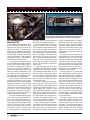
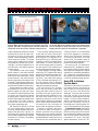
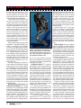
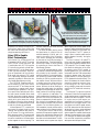
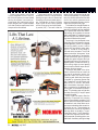
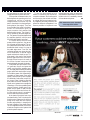
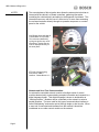
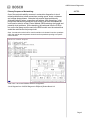
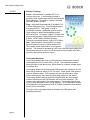
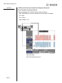
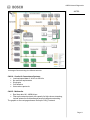
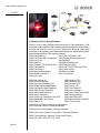
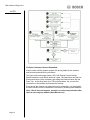
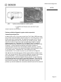
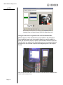
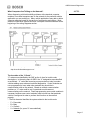
40
July 2007
Meddle With the Pedal:
ELECTRONIC
THROTTLE
CONTROL
BY MIKE DALE
I
t may well be that software integration of
automotive electronic systems will turn out
to be the most significant automotive technological development of this decade. Originally electronic systems such as ABS, HVAC
and emissions were developed separately by
those groups within each carmaker that were most
responsible. The brakes and suspension group
worked on ABS while emissions and engine control
issues were handled by powertrain people. Software
integration has brought these systems together. The
result is new, interrelated technologies that produce
better mileage, safer cars and reduced emissons.
At the head of this trend, as an enabling technology, is electronic throttle control (ETC), which is part
of an industrywide response to calls for better fuel
economy, reduced emissions and a reduction
in vehicular fatalities. This story is
not so much about hardware as
it is about software that uses
ETC as an input and an actuator to make the new technologies possible.
Without ETC, the planned advances in hybrid and diesel technology that are now
right around the corner would not be possible. Cur-
rent advances such as electronic stability control
(ESC), expected to save thousands of lives per year,
would simply not be possible without ETC. Best yet,
ETC reduces cost and complexity for carmakers by
integrating formerly stand-alone features such as idle
control, cruise control and throttle control into a single, mostly software-based system.
This latest version of electronic throttle control
should not be confused with the earlier stand-alone
systems that replaced the mechanical link between
the driver and the engine. In these new systems, the
output of the pedal sensor is an input not only to the
engine control system but to the software system as a
whole. As such, pedal angle becomes a valuable input
to other electronic control systems. The algorithms
that control the ABS, ESC, cruise control, HVAC and
other system functions all use pedal angle data in the
decision-making process. The throttle angle that results is not only what the driver wants but what the
systems needs for correct and safe operation.
In these new-generation ETC systems, the accelerator pedal module becomes a two-way device: It
accepts information about desired engine output
from the driver, plus it can feed back tactile information to the driver as a warning that the selected engine output is either wrong or dangerous.
July 2007
Photoillustration: Harold Perry; Images: Mikuni Corp., Abletronik & Jupiter Images
Doing away with the throttle cable was just
the beginning. Electronic throttle control
(ETC) has allowed engineers to add many
other noteworthy vehicle systems and
capabilities, with more to follow.
41
Photos courtesy Chrysler
ELECTRONIC THROTTLE CONTROL
This is the roller lifter used in Chrysler’s cylinder shutdown
system. Oil flow regulated by a computer-controlled solenoid unlocks the lifter to prevent the valve from opening.
The Technological
Need for ETC
The clear goals of the automotive industry are to improve fuel economy, reduce
emissions and improve function and
safety for the driver. To understand the
design options available to accomplish
these goals, you need to know what produces the best results and what causes
subpar performance. These complicated goals are further complicated by
trade-offs that have to be made.
Fuel economy and emissions output
per mile traveled are directly related to
the size of the vehicle and the size of
the engine. In keeping with the laws of
physics, cutting fuel consumption is
about either reducing the mass of the
vehicle or reducing acceleration. Since
the systems are not perfect, there’s another path that can be traveled—by improving efficiency to reduce losses.
The first thing to know is that most
automobile engines are much larger
than they need to be for most real-world
operating conditions. The big V8 often
selected for full-size pickups is really
chosen to pull a boat or trailer the owner
may have in mind. Yet trailer towing
may amount to less than 10% of the actual vehicle miles; 90% of the time a
smaller engine would do just fine.
The fact that engines generally spend
most of the time running at a small fraction of their peak power output is referred to as the partial power problem.
Toyota says the Otto cycle engine is most
efficient at 40% to 45% of its redline
rpm. This is the point at which torque is
at about 70% to 80% of its peak value
for a given engine. In this most efficient
42
July 2007
operating range, the engine produces
about 40% of its peak power rating.
Let’s use Toyota’s 108-hp ECHO engine as an example. Given the numbers
just mentioned, it would be best if most
of the time the engine output were in
the range of 40 to 50 hp. Unfortunately,
this is not enough for adequate acceleration or hill climbing. Calculations show
that if the ECHO had only a 30-hp engine, it would need 30 seconds to accelerate to 60 mph. If such a vehicle were
to encounter a 10% grade, it would slow
down to 30 mph before it reached the
top of the hill.
On the other hand, only 15 hp or so
is needed to maintain 60 mph on level
roads, and even less power is needed
for idling and low-speed travel. The net
result is that the engine power output
that was chosen for adequate passing
and hill-climbing is larger than necessary for most of the operating circumstances of the vehicle.
In addition, engines are seldom operated under the circumstances that
would produce the best results for fuel
economy and emissions output. For a
typical engine with a redline of 5000
rpm, the sweet spot should be at about
2000 rpm. In practical terms, most engines actually operate in a much broader range between idle and 3200 rpm.
There are the occasional zooms to redline, but they represent a small part of
the true operational circumstances.
Given normal gearing, the peak efficiency point for a vehicle turns out to be
around 55 mph. The double-nickel
speed limit was not chosen randomly,
but rather with an eye to best fuel econ-
omy for the average vehicle. For a given
distance traveled, fuel economy tapers
off at both higher and lower speeds.
Holding a constant speed is an advantage, as it avoids both the extra fuel
needed for acceleration and the increased emissions that often result from
deceleration.
Not surprisingly, the sweet spot of
engine efficiency is also the sweet spot
of emissions output. It’s the cold-start
events and sudden speed changes that
challenge emissions control systems.
Electronic throttle control can actually
help emissions through strategies that
lean out the mixture in concert with retarded ignition timing to assure an earlier light-off for the converter.
Efficiency losses occur on both sides
of the sweet spot for a given engine. At
high engine speeds, friction among the
piston, the rings and the cylinders accounts for more of an engine’s lost output. These friction losses become more
significant as engine size is reduced.
Parasitic losses to engine accessories
such as the oil and water pumps also increase as a function of rpm. Another issue is the need to richen the fuel mixture to get maximum torque output
from the engine. It may help acceleration but it doesn’t help emissions output
or fuel consumption.
The major cause of efficiency losses
at low speed is called pumping loss. Reducing the output of an engine is accomplished by limiting the airflow into
the engine. The throttle plate restricts
the intake of air by forcing the engine to
drag air through a narrow or restricted
inlet. The restriction of the air intake
The black trace at the bottom of this screen capture shows
how the MDS switches between four-cylinder and eightcylinder operation. At higher speeds the load is lower and
the portion of the time in four-cylinder mode increases.
creates a differential pressure across the
throttle plate we know as intake manifold vacuum. Since the air entering the
cylinder is below atmospheric pressure,
less air enters the cylinder. The engine
control system measures the pressure
differential and reduces fuel input accordingly. The reduced quantities of air
and fuel result in the desired reduction
of power output.
The downside to this is that having
partial pressure in the intake manifold
wastes energy. As the piston moves
downward on the intake stroke, normal
pressure below it and partial vacuum
above it cause drag on the rotation of the
crankshaft. These pumping losses occur
during most engine operating conditions,
as the throttle is seldom truly wide open.
Diesel engines are known to be approximately 25% more efficient than
gasoline engines. According to Toyota,
one reason is that the diesel engine uses
no throttle, and thus suffers reduced
pumping losses. In gasoline engines, the
throttle-related losses are believed to be
in the range of 7% to 10%. Diesel engines are also more efficient due to
their higher compression ratio.
GM says that it’s difficult to achieve
all of the design goals of better fuel
economy, reduced emissions and driver
safety at the same time. Typically, in a
fixed-valve-timing engine, best power
has be traded off against other desirable
elements such as torque, idle stability
and fuel economy.
44
July 2007
Photo courtesy Mikuni Corp.
Waveform courtesy Chrysler
ELECTRONIC THROTTLE CONTROL
The stepper motors on these throttle bodies are mounted
on the side. With direct computer control, the throttle angle
can be changed to adapt the engine throttle setting in
keeping with the results of the computer’s algorithm.
There are other approaches that try
to deal with the issue of the throttlerelated partial power problem. Gasoline
direct injection is an approach to improving efficiency by calibrating each
combustion event to the needed power
requirements. The direct injection system controls engine power by injecting
only that amount of fuel needed to produce the desired engine power output.
Another approach is through variable
valve timing. VVT systems offer varying
degrees of control based on system complexity limits. Early intake valve closing (EIVC), late intake valve opening
(LIVO), late intake valve closing (LIVC)
and fully variable valve lift strategies
have demonstrated reduced pumping
losses and improved fuel economy.
GM has tried the EIVC strategy,
which uses the variable intake valve
closing and intake valve lift control to
unthrottle the engine at part-load and
light-load operating conditions. Here
the intake valve duration and lift are
significantly reduced to control airflow
into the engine, allowing it to operate at
higher intake manifold pressures with
the potential to fully unthrottle the
engine under all operating conditions.
Electronic or hydraulic valve actuation solenoids under the direction of
software-controlled cam profiles may
someday offer even greater flexibility.
These systems have been talked about
and demonstrated. Renault had one in a
Formula One racer a while back with a
17,000-rpm redline. So far the software
cam has not appeared in a production
vehicle due to the dynamic complexity
of landing the valve back on its seat
without noise. The actuators shown so
far are also bulky and expensive in comparison to mechanical actuation.
According to GM, the downside to
these various VVT strategies for production engines is that they require moderate to significant changes to the engine’s
architecture to successfully package the
VVT components. Cam phasers not only
take up space, but also add to the vehicle
in terms of complexity, weight and cost.
Using ETC to Achieve
System Goals
Automakers have taken this research
into engine efficiency and done their
best to make sure the engine spends
more of its time in and around the
sweet spot. They know that the vehicle
has to feel “normal” to the driver and
have gone to great lengths to make that
happen. From the driver’s standpoint,
what the computing platforms are adjusting and controlling is strictly in
the background. Getting greater efficiency is accomplished in several ways:
Transmission Control. Keeping the
engine at its rpm sweet spot is accomplished by having more of the need for
rpm compensation between the engine
and the drive wheels handled by the
transmission. Six-, seven- and eightspeed transmissions, as well as CVTs,
are becoming commonplace. As CVTs
are still limited in their peak torque
handling capability, vehicles with highoutput engines have stayed with conventional multispeed transmissions.
Ford and GM are in production now
on their joint venture six-speed transmission. About 85% of the components
are meant to be shared by both manufacturers. Expectations are for a 4% increase in fuel economy while at the
same time providing a 7% improvement in 0-to-60 times. Unlike conventional transmissions, with their ratio
spread of approximately 4.0 to 1.0, the
new Hydramatic/Ford transmission has
a wider overall ratio of 6.0 to 1.0. Electronic throttle control is an integral part
of the improvements in both fuel economy and acceleration.
Having so many gears requires some
adaptations. Toyota’s eight-speed transmission, for example, has a software
provision to skip gears during deceleration to make the downshifting smoother
and less apparent to the driver. The
ETC system smoothes the shift performance between gears by adjusting the
throttle opening at the shift point. Programmed steps in the ETC system can
be used to give the driver the “feel” of a
conventional transmission, so the CVT
doesn’t feel odd.
Driveline management software is
used to select the combination of engine
output and gear ratios that will deliver
the needed torque in the most efficient
way. The software is capable of reducing
the torque input to the transmission
during the shift sequence to reduce mechanical shock to the drivetrain. This
driveline management software is especially important for on-demand AWD.
The shift from two-wheel to four-wheel
drive must be controlled to avoid torque
bumps and other interactions between
the drive wheels.
Displacement Reduction for
Light-Load Conditions. GM, Chrysler
and others have implemented variable
displacement strategies. GM’s Displacement on Demand system reduces effective engine size during steady-state, lowpower conditions. A key aspect of this
system is the ETC system’s ability to create a greater throttle angle without the
need for the driver to change pedal an-
46
July 2007
Photo courtesy Abletronik
ELECTRONIC THROTTLE CONTROL
What was once a simple pedal and
spring arrangement has become a
highly sophisticated sensor/actuator. Triple redundant systems assure that the driver’s intent gets to
the computer without error.
gle. This is a key element to assuring
that the only indication to the driver that
four of the V8’s cylinders are deactivated
is the light on the dash.
Emissions Control. ETC is a part of
the strategy to reduce engine emissions
during cold start-up. One way to cause
quick heating in the catalytic converter
is to retard timing and lean out the mixture. The ability to do this is limited by
the loss of torque and power that results
from these engine settings. For a given
pedal position, the driver will feel reduced power when the strategy is implemented. Software compensations to
the throttle angle can be made that
maintain the original pedal-to-throttle
relationship the driver is used to.
ETC also can be used to control actual throttle angle during acceleration and
deceleration to minimize pumping losses. Often the throttle angle implemented
by the ETC system could be more favorable than the driver is able to select.
The greatest impact on emissions
performance of ETC systems is the
above-mentioned variable displacement
strategies. Cadillac’s first attempt at variable displacement (V-8-6-4) in the early
’80s foundered at the time for a variety
of reasons, including driver dissatisfaction with how the engine “felt” as it
dropped or picked up displacement.
ETC, with its computer control, is able
to automatically make the throttle angle
changes needed so the change is seamless to the driver.
Another benefit of ETC, according
to GM, is the ability to modify vehicle
response to a change in pedal angle position. Consumer research shows that
vehicle response to accelerator inputs
greatly affects a driver’s overall satisfaction with the vehicle. The response of
the vehicle to the first 20mm (.8 in.) of
throttle movement may be more important than the actual 0-60 acceleration
time.
Vehicle Safety. Electronic stability
control is probably the most significant
safety development since the invention
of the seat belt. By federal requirement
and automaker cooperation, this system
will be standard on all vehicles by 2010.
The hope is that as many as 10,000 lives
per year will be saved. To function as it
does, ESC depends on ETC.
Electronic stability control systems
are an integration of existing vehicle systems (ABS, TC, ECM), coupled with
added sensors to determine steering angle and yaw. A key input to the system is
the pedal angle position sensor output.
The ESC system runs an algorithm that
determines if the requested engine output is safe. When it’s advisable, the output from the system can be a throttle angle command that’s not what the driver
requested. When there’s a possible loss
of traction and/or steering control, the
ESC system can overrule driver input to
reduce throttle angle and engine power.
Electronic throttle control can also
be used to protect the engine, driveline
and tires from operation that may cause
excess wear or damage. Rev limiting
can be accomplished in software by
governing the throttle angle rather than
cutting off fuel or ignition. This results
in a much smoother limiting that does
not cause the driver to sense that the
engine has “cut out,” as can be the case
with ignition- and fuel-based limiter systems. Rental car companies have
The stepper motor positions the throttle plate
according to the results of the computer’s throttle
position algorithm. The gear train increases the
resolution so the plate can be set with high accuracy.
pushed for rev limiters as a way of protecting their assets from drivers who
don’t care how hard they push a vehicle
simply because they don’t own it.
Using ETC to Enable
Other Technologies
GM’s Vortec 5.3L V8 uses Active Fuel
Management (AFM), with ETC as a key
input. The 3.9L V6 also uses AFM, but
in combination with VVT. GM says the
3.9 is the first to use both cylinder deactivation and VVT on the same engine.
Under light-load conditions, either engine can deactivate half the cylinders.
Real-world fuel savings of 7% is what
GM is advertising, although the benefit
reportedly is greater for those who do a
lot of steady-state highway cruising.
The E38 ECM measures load conditions based on inputs from vehicle
sensors such as ETC and interprets that
information to manage more than a
hundred engine operations. Fuel injection, spark control and electronic throttle control are all included. When loads
are light, the engine computer automatically closes both the intake and exhaust
valves, while at the same time cutting
fuel delivery. When the driver demands
acceleration or increased torque to move
a load, the cylinders are reactivated.
In these systems, ETC is used to balance torque to prevent the driver from
“feeling” the cylinders as they come or
go off-stream. During deactivation,
both valves are closed. The energy used
to compress the air in the cylinder is returned to crankshaft on the downstroke
as the trapped air acts as a spring. The
48
July 2007
The dual and offset outputs from the pedal
angle sensor are a form of redundancy
that guarantees the accuracy of the
output. Some pedal assemblies can
feed back to the driver tactile information about the correctness
of the desired throttle angle.
transition takes less than 20mS, and the
driver never notices it.
The actual hardware used to control
the deactivation is called a lifter oil
manifold assembly (LOMA), and is located in the valley of the V8 engine.
Four electric solenoids are controlled
by the result of the E38’s processing of
the load algorithm. These solenoids determine the number of active cylinders
by controlling oil flow to the lifters of
the affected cylinders.
In an AFM-equipped engine, pumping losses are reduced during deactivation primarily by the increase in intake
manifold pressure. During deactivation,
the remaining cylinders need reduced
throttling in order to provide an equivalent amount of work. Without electronic throttle control, the driver would notice the deactivation as a sag in performance. Without the driver needing to
change the pedal angle, the software
changes the throttle angle to reflect the
fewer number of functioning cylinders.
AFM operation is load-based. The
load is measured and combined in an algorithm with the driver’s demand for
power as measured by throttle application. Active fuel management does not
affect emissions output from the active
cylinders. For the inactive cylinders, no
fuel is wasted or burned, and the result is
lower emissions for the distance traveled.
The key point here is that the only
mechanical components needed are the
three or four special valve lifters and the
solenoids to control them for the cylinders that are to be deactivated. The software-based control system uses inputs
about engine load, vehicle speed, driver
intention, safety and emissions inputs in
making the decision to shut down individual cylinders. The ETC system already in place is used to make sure the
vehicle operates “normally” during the
deactivation.
The Gen IV Vortec 5.3L takes ETC
to the next level by taking advantage of
the processing capability available in the
E38 computer. The increased integration allows the elimination of the throttle actuator control (TAC) module. In
previous systems, the TAC module took
commands from the ECM and operated
the electric stepper motor that controls
throttle position. In the new system, the
ECM operates the throttle directly. This
direct link between the throttle and the
computer speeds up response time.
Eliminating the TAC also reduces
wiring, reliability issues and the need to
monitor the TAC module for correct operation.
The flex-fuel 5.3 requires no special
fuel sensor. Earlier flex-fuel engines used
a light-reactive sensor to determine what
blend of fuel was in the system. The Gen
IV engine uses a virtual sensor programmed into its software. Based on
readings from the oxygen sensors, fuel
level sensor and vehicle speed sensors,
the ECM determines the fuel blend and
adjusts the fuel injector pulse width and
the throttle angle as required. The ETC
system makes the needed throttle angle
changes. Because ethanol has a lower
BTU rating for the same volume as gasoline, more fuel is required to provide the
same power at wide-open throttle.
Illustrations courtesy University of Toyota
ELECTRONIC THROTTLE CONTROL
ELECTRONIC THROTTLE CONTROL
Toyota is using what it calls Power
Train Management on the Lexus LS
460. With this system, the most suitable
vehicle drive power is accurately accomplished with optimized engine
torque and gear ratio. Toyota’s emphasis
is on what the driver experiences, which
is torque at the drive wheels.
Toyota says that with conventional
powertrain controls, a target throttle
opening and gear ratio are determined
according to the driver’s pedal angle input. Consideration in terms of throttle
angle is given to other vehicle systems
such as cruise control and vehicle stability control (VSC). The result is that the
Circle #27
Circle #28
Circle #29
Circle #30
50
July 2007
target throttle opening and target gear
ratio are set separately. In previous systems, this situation worked well because
each of the vehicle systems was not
large, and the desired accuracy requirements were not particularly high.
This situation has changed. Newer vehicle systems with precrash safety systems and intelligent parking assistance
(IPA) systems have caused the relationships among vehicle systems to become
more complicated. It has become more
difficult to align all the different systems
to achieve the desired drive power.
Toyota says it has developed something called Vehicle Dynamics Integrated Management (VDIM) to integrate
the vehicle stability control, traction
control, ABS and electric power steering. ETC is used for VDIM sensor inputs and control actuators. The VDIM
system controls the “drive power” by selecting the combination of engine power and transmission gear to give the
needed drive wheel torque at the highest possible efficiency. By having an integrated system, the best choices for ignition timing, engine rpm and gearing
can be chosen to deliver torque and acceleration the driver senses.
The torque and power of the drivetrain for hybrid vehicles can come from
the internal combustion engine, the
generator and/or the electric motor.
Combining and distributing the torque
is handled by a planetary gearset that
both Toyota and Ford call a power split
device (PSD). In the PSD, the carrier
gear is connected to the engine, the sun
gear is connected to the generator and
the ring gear is connected to the electric
motor. The planetary gear configuration
provides decoupling of engine speed
from vehicle speed.
While a hybrid drivetrain offers the
possibility of improved fuel economy,
there are some added constraints. Ford
says one issue is that power split vehicles
are sensitive to such noise factors as engine torque mismatches that conventional vehicles are not. These systems are
also sensitive to overuse of the battery
that may affect its durability. To overcome these issues, Ford Escape/Mercury Mariner engineers had to determine powertrain operating points compatible with the battery and high-voltage
bus architecture to ensure that power,
voltage and durability issues were met.
Ford says that the determination of a
desired powertrain operating point for a
conventional vehicle is relatively
straightforward, since there’s only one
path to the wheels from the power-generating device (the engine). There are
three variables that need to be determined—the transmission gear, the
torque converter clutch state and the
desired engine torque. The driver’s intent is reported by the pedal angle sensor. The gear and torque are determined
by computer algorithm, with the result
that the throttle angle is controlled.
In a hybrid vehicle, there are three
power-producing devices—the generator, the motor and the engine. The control system determines what the driverdemanded wheel torque is by way of
the pedal angle sensor. From this, the
computer software can choose the optimum combination of desired engine
speed and desired wheel torque. Engine speed is the result of the throttle
position algorithm’s control of the throttle angle. Wheel torque is the result of
the choice of power sources and the
gearing between them and the wheels.
In the power-split hybrid electric vehicle, generator torque and generator
speed—and, therefore, generator power—are largely determined by the desired
engine speed and actual engine torque.
So the battery power limit is essentially a
constraint on motor power. Since motor
speed is determined by vehicle speed,
this effectively limits motor torque. Motor torque is also limited by what the
driver wants in terms of driveability. The
hybrid control system has to manage the
interactions of the three possible power
sources. Electronic throttle control integrated into the system is used to accept
the input of the driver and to then control the engine’s output in accordance
with the other two sources of power.
At the heart of the hybrid control system described by Ford is the electronic
throttle control system and its ability to
accept driver input and then output a
throttle angle position in keeping with
the best interests of the whole system.
It’s the integrated software of the transmission and engine control systems that
gives the system response.
To sum up, what started out as a
means of eliminating the mechanical
connection between the throttle pedal
and the engine has evolved and taken
on a larger and far more important role.
By integrating the safety, emissions and
powertrain electronic subsystems, it has
become possible to implement new
technologies that could not have been
implemented independently. Electronic
throttle control is a mandatory element
of these advanced systems.
Visit www.motor.com to download
a free copy of this article.
Circle # 31
July 2007
51
OBD II Network Diagnostics
Diagnostics Using OBD II
Data Bus Communication Networks
NOTES:
Overview:
Vehicle On-Board Control Modules are changing the automotive industry in
two related areas. The first area concerns the expansion and use of multiple
on-board control units. Today’s modern vehicle will have on-board control
modules controlling vehicle components such as the engine, antilock braking
system, transmission, instrument panel, chassis and body control functions,
to name just a few. An on-board control module does more than just make
sure its own input and output devices work correctly. The on-board controller
also participates and communicates in one or more communication networks
in the vehicle. These vehicle networks exist to allow the sharing of
information among components and to reduce the numbers of wires and
sensors required in the vehicle.
The second area in which
microcontrollers are changing the
automotive industry concerns the
way we interact with our vehicles.
Computers are now common in the
passenger area and consumers
can now interact with their vehicles
in a variety of ways. This allows
consumers to run already familiar
programs in the vehicle — email,
GPS navigation, calendar
management, etc.
Lexus Navigation Center
Page 1
OBD II Network Diagnostics
NOTES:
The second phase of this migration also allows the automotive technician to
interact with the vehicle’s on-board controllers, gathering information,
controlling the vehicle directly and aiding in the diagnosis of problems. This
interaction can occur with the use of a scan tool or in some case accessing
the on-board controller directly through an operation sequence or a control
panel on the vehicle.
2005 Dodge Neon with Idle Air
Control Motor DTC (P0508).
This code was obtained by
cycling the ignition key on/off
three times. Notice how the
code is displayed directly on
the dash panel.
KTS 200 Communicating
with Generic OBD II
interface. Robert Bosch LLC
Network and Scan Tool Communication:
An automotive controlled network consists of multiple series of control
modules electronically communicating complex information and requests in a
digital language format. This digital language is known to technicians as
“vehicle protocols”. Modules can be connected on the network in serial or
parallel interface. The term used for this type of communication interface is
called “Multiplexing” and can be carried through single or dual circuits. When
a scan tool is connected and interfaced into the network it should be
considered as one other control module on the network.
Page 2
OBD II Network Diagnostics
Primary Purposes of Networking:
NOTES:
One of the major driveability concerns in automotive diagnostics is circuit
related problems due to bad connections creating opens, shorts, resistance
and voltage drop problems. Networks help resolve these problems by
eliminating miles of wires, connections and splices. With networking, a fuel
pump circuit that would normally be wired to the PCM to be commanded on
could now be wired to a Rear Control Module (REM) reducing wire length and
potential circuit problems. With networking, the command from the PCM to
turn on the fuel pump could be sent to the REM module over the network that
would then activate the fuel pump circuit.
Note: As networks evolve look for control modules to be located in various quadrants
within the vehicle and components located near that quadrant reporting to a specific
control module.
2004 Volvo S 80 Control Module Network Configuration.
Circuit Diagram from CAS/SIS Diagnostics ESI[tronic] Robert Bosch LLC
Page 3
OBD II Network Diagnostics
NOTES:
Network Topology:
Linear: Interconnection of multiple ECU’s on
common linear bus. A multi-master principle is
generally used, allowing high stability with enhanced
fault localization. This system is used in drivetrain
and body network systems.
Ring: Short path interconnection of multiple ECU’s
in a fiber-optic series ring. The information passes
through each ECU. This system is used in
multimedia networks. Multimedia systems require
large volumes of data to be transferred in short
amounts of time. To transmit a digital TV signal with
stereo sound requires a data transfer rate of around
6 Mbit/s. MOST (Media Oriented Systems
Transport) can transfer data at a rate of 21.2 Mbit/s.
Star: Interconnection of multiple ECU’s in a star
structure network control by central master ECU.
This system uses a master-slave, time triggered
protocol. The network is designed as a low cost, local sub-system single wire
interconnect network for use in on-off devices such as car seats, door locks,
sunroofs, rain sensors and door mirrors.
Terminating Resistors:
Terminating resistors are used in CAN systems to create proper electrical
load between the CAN_H and CAN_L circuits. This load helps to reduce
electrical noise on the data circuits, which allows for a cleaner voltage signal
on the data bus.
Terminating resistors in the high speed CAN systems are required to be 120
ohms with a maximum range of 118-132 ohms. Lower speed CAN systems
may use different values. CAN systems can use split termination, which
means there may be more than two terminating resistors in the system.
Terminating resistors may be physically located inside any of the control
modules connected to the CAN harness, with a junction connector. The
resistors may also be part of the wiring harness. Terminating resistors may
or may not be identified in circuit wiring diagrams. Do not attempt to conduct
wiring diagnostic fault procedures such as voltage or resistance tests without
proper service information.
The figure on the next page shows an example of a CAN system with
terminating resistors.
Page 4
OBD II Network Diagnostics
NOTES:
Signal protocols:
There are five basic signal protocols currently in use with the OBD-II
interface.
SAE J1850 PWM
SAE J1850 VPM
ISO 9141-2
ISO 14230 KW
ISO 15765 CAN (C&B)
Pin #
Pin Assignment
1
Pin #
Pin Assignment
9
2
SAE J1850 (SCP Bus +)
10
SAE J1850 (SCP Bus -)
3
ISO 15765-4 CAN MS (Bus +)
11
ISO 15765-4 CAN MS (Bus -)
4
Chassis Ground
12
5
Signal Ground Return
13
6
ISO 15765-4 CAN Hi (Bus +)
14
ISO 15765-4 CAN Low (Bus -)
7
K Line of ISO 9141
15
L Line of ISO 9141
16
Fused Battery Power
8
Page 5
OBD II Network Diagnostics
NOTES:
J1850 from the Society of Automotive Engineers Protocols:
Ford “Standard Corporate Protocol”:
Protocol operates at 41.6 kB/sec with two wires on the bus.
_ SAE J1850 PWM (41.6 kbaud, standard of the Ford Motor Company)
_ Pin 2: Bus_ Pin 10: Bus+
_ High voltage is +5 V
SAE J1850 PWM
MTS 5100 Robert Bosch LLC
Page 6
OBD II Network Diagnostics
General Motors Class 2 Bus:
NOTES:
Protocol operates at 10.4 kB/sec with one communication wire. Chrysler also
has an adaptation of the GM Class 2 protocol.
_ Pin 2: Bus+
_ Bus idles low
_ High voltage is +7 V
_ Decision point is +3.5 V
_ Message length is restricted to 11 bytes, including CRC
SAE J1850 VPM
ISO 9141-2 from the European-influenced International Standards
Organization:
This is a single-wire where the ISO modules talk only when asked and only to
the scan tool, not to each other. This protocol is slower than GM and
Chrysler versions of SAE J1850. The ISO 9141-2 protocol has a long
wake-up call which allows for each control module to report PID data.
ISO 9141-2 protocol has a data rate of 10.4 kbaud and is primarily used in
Chrysler, European and Asian vehicles.
Page 7
OBD II Network Diagnostics
NOTES:
_ Pin 7: K-line
_ Pin 15: L-line (optional)
_ UART signaling (though not RS-232 voltage levels)
_ K-line idles high
_ High voltage is Vbatt
Just because a vehicle has an ISO protocol does not mean that the control
modules are unable to talk to each other. An example would be a 2001
Volkswagen Passat where the modules talk to each other on a CAN protocol
network. The CAN protocol is then transmitted to the IP instrument cluster
module where the signal protocol is converted to ISO format for
communication with the scan tool.
ISO 9141-2
ISO 14230:
In use by 1997, ISO 14230 was an upgrade to ISO 9141-2. One of the major
enhancements of ISO 14230 was a faster wake-up call.
_ ISO 14230 KWP2000 (Keyword Protocol 2000)
_ Pin 7: K-line
_ Pin 15: L-line (optional)
_ Physical layer identical to ISO 9141-2
_ Data rate 1.2 to 10.4 kbaud
Page 8
OBD II Network Diagnostics
CAN Systems:
NOTES:
Controller Area Network (or CAN) is the latest communication system within
the automotive world. CAN is a means of linking all of the electronic systems
within a car together to allow them to communicate with each other. As
on-board computers increase, so does the number of different electronic
systems. Today’s modern vehicles may have as many as 50 or more
on-board computer systems on them. The information recorded and
processed by each control module is often used by one or more control
modules on the system. A requirement for a standardized means of quickly
passing information between the control modules was needed leading to the
development of CAN.
CAN History:
CAN protocol was created in 1984 by Robert Bosch Corporation with
anticipation of future advances in on-board electronics. The first production
application was in 1992 on several Mercedes-Benz models. CAN is now
being used on more and more new vehicles. By 2008, all new vehicles sold
in the U.S. will be required to have a CAN-compliant diagnostic system.
CAN Protocols:
ISO 15765 (CAN-B&C)
CAN-B, the medium-speed network (nominally about 125 kB/sec), will be
used for body electrical systems and normally will operate at 83.3 kB/sec. On
some Mercedes cars, there may be as many as 30 modules on the CAN-B
bus.
_ Pin 3: CAN High
_ Pin 11: CAN Low
CAN-C is a 500 kbit/s high speed two-wire system for powertrain,
transmission and ABS modules. CAN-C is intended to operate at a
500 kB/sec baud rate, about 50 times faster than GM's Class 2 data bus
version of J1850 and over 60 times faster than ISO 9141-2.
_ Pin 6: CAN High
_ Pin 14: CAN Low
Note that Pins 4 (chassis ground), 5 (signal ground) and 16 (battery positive)
are present in all configurations.
The next page shows a CAN_High and CAN_Low waveform.
Page 9
OBD II Network Diagnostics
NOTES:
Screen Capture using KTS 570 lab scope Robert BoschLLC
Internal CAN Communication:
CAN networks can communicate internally, but not with the scan tool. Many
CAN modules will talk with each other and a gateway; or translator module,
will convert the protocol so a scan tool can understand it.
CAN Translators VW Example:
Instrument clusters from 08.99 > are integrated into the vehicle CAN Data
Bus network. The CAN-Bus on-board diagnostic Interface “J533” (which is
integrated into the instrument cluster) enables data to be exchanged between
the vehicles CAN Data-Bus network and the Data Link Connector (DLC)
“K-wire”.
The CAN-Bus On-Board Diagnostic Interface “J533” has specific on-board
diagnostic (OBD) capabilities that are accessed by using scan tool address
word 19 – “Gateway”.
The next page shows a network diagram of a VW Passat with three different
networks.
Page 10
OBD II Network Diagnostics
NOTES:
Volkswagen Passat showing four different networks
CAN A: Comfort & Convenience Systems:
• Low/med speed data of 1k bit/s to 20k bit/s
• No real-time requirements
• Single wire
• Cost effective
• Uses various protocols
CAN D: Multimedia:
•
•
Real time data 1M – 400M bit/sec
Fiber-optic network protocol with capacity for high-volume streaming,
include automotive multimedia and personal computer networking.
The graphic on the next page shows a fiber-optic CAN_D network.
Page 11
OBD II Network Diagnostics
NOTES:
CAN-B
Audio
Aux
MOST
Video line
Lin
CAN-D
A Growing List of CAN Applications:
Below is a list of some vehicles that are currently in CAN compliance. CAN
compliant means that the CAN network broadcasts diagnostic information to
the scan tool (Pins 6 & 14 or 3 & 11) in CAN protocol language. Many scan
tools have to be updated with CAN module adapters to communicate at the
higher baud rates that CAN systems produce.
2003 Ford Excursion
2003 Ford Focus and Thunderbird
2003 Lincoln LS
2003 Saab 9-3
2004 Cadillac CTS, XLR and SRX
2004 Ford Explorer
2004 Ford Taurus
2004 Mercury Mountaineer
2004 Mazda 3 and RX-8
2004 Volvo S40
2003 Ford F-250 and F-350
2003 General Motors Saturn ION
2003 Mazda 6
2004 Buick Rendezvous
2004 Dodge Durango
2004 Ford F-150, E-250 and E-350
2004 Lexus LS430
2004 Mercury Sable
2004 Toyota Prius
2005 Audi A4 and A6
2005 Chevrolet Equinox
2005 Chevrolet Trailblazer EXT
2005 Dodge Dakota and Magnum
2005 Ford Escape and Expedition
2005 GMC Envoy ESV and XL
2005 Jeep Grand Cherokee
2005 Lincoln Town Car
2005 Pontiac G6, Grand Prix and GTO
2005 Mazda MPV and Tribute
2005 Saab 9-7X
2005 Cadillac STS
2005 Chevrolet SSR
2005 Chrysler 300C
2005 Ford E-150
2005 Ford Freestyle
2005 Isuzu Ascender
2005 Lexus LS400 and GX470
2005 Mercury Mariner
2005 Land Rover LR3
2005 Mercedes-Benz SLK350
2005 Toyota Avalon
2005 Buick LaCrosse, Rendezvous and Rainier
2005 Chevrolet Cobalt, Corvette and Malibu
2005 Mercury Grand Marquis, Montigo and Sable
2005 Ford Crown Victoria, Five Hundred, Focus and Mustang
2005 Toyota 4Runner, Sequoia, Tacoma and Tundra
2005 Volvo S60, S80, V50, V70, XC90
Page 12
OBD II Network Diagnostics
Strategy Based Diagnostics
NOTES:
General Motors developed strategy-based diagnostics for their technicians
and the diagnostic procedure can be used on all vehicle applications.
• Verify the customer concern: A technician needs to know how the system
is supposed to function normally before deciding that the system is
malfunctioning. A thorough customer interview, or a diagnostic worksheet
filled out by the customer, is necessary before troubleshooting can begin.
• Preliminary checks: Operate the suspect system and evaluate its
performance. Perform a thorough visual inspection of all components,
including fuses, connectors, grounds and harness routing. This is also an
ideal time to pull up the service history on the vehicle.
• Perform published diagnostic system checks. If there is a published
diagnostic procedure that will help you narrow down the cause of the
problem, use it first.
Note: This is the time to connect the scan tool and request diagnostic
information from the control modules on the network.
• Check for bulletins: If you have access to published service bulletins for
the vehicle, search those for a possible fix. This can save time in the long
run. You can also print safety bulletins for your customers at this point, as an
added value.
• Stored diagnostic trouble codes (DTC’s) and symptoms with no
DTC's: If there is a hard trouble code, then follow the diagnostic procedure
for the particular DTC. If you have a repeatable symptom, then use the
Symptom Charts. Both these procedures will quickly help you narrow your
diagnostic focus.
• No published diagnostics: When there is no DTC stored and no
matching symptom for the condition in the service manual, you will have to
develop your own diagnostic process based on your understanding of how
the circuit operates. This is the time when there is no substitute for advanced
systems training.
The graphic on the next page shows the diagnostic flow chart for Strategy
Based Diagnostics.
Page 13
OBD II Network Diagnostics
NOTES:
Verify the Customer Concern Expanded:
Know how the vehicle systems operate, the driving habits of the customer
and the environmental driving conditions.
The figure on the next page shows a 2001 VW Passat Central Locking
Module located in a pan below the driver’s seat. Mud and snow can leak into
this box and short out the computer, thus killing the communication with the
Scan Tool. At this time there is no TSB on this problem, but you can find
information on the problem by browsing the Internet.
Even though the Internet is a great resource for information, you should take
the time to make sure the information is accurate by checking other websites.
Note: Bosch does not support, promote, or endorse any websites other
than its own company website (www.Bosch.com).
Page 14
OBD II Network Diagnostics
NOTES:
Graphic captured from the Internet
Perform published diagnostic system checks expanded:
Connecting the Scan Tool:
Is there power on Pin 16 to power-up the Scan Tool? Many OEM scan tools
may not have internal batteries and will require Pin 16 to have power in order
for the scan tool to communicate. Be aware that no power on Pin 16 may
affect some aftermarket scan tools (consult your operator’s guide). Many
times Pin 16 will not have power due to something as simple as a blown
cigarette lighter fuse. Remember Pin 16 is Battery Power Un-switched.
Many technicians panic when their scan tool doesn’t power up off the 16 Pin
connector. In some cases the technician will think the computer or
computer(s) are dead and not communicating with the scan tool. A quick
work around is to power up the scan tool through an alternate battery source
or AC power source. Remember Pin 16 has nothing to do with
communication, it is only there to power up your scan tool for diagnosis.
Pins 4&5 are also important as one of these grounds will be needed for your
Scan Tool to power up the OBD II link and establish a reference link for scan
tool communication. If you are having communication problems it is
imperative that you check the integrity of these grounds. In some instances
one of these grounds may be open or have high resistance. There is also a
possibility that the scan tool might complete a ground that is faulty when the
scan tool is not connected. If the OBD connector has power or ground
problems you should validate the connections when the scan tool is removed.
Page 15
OBD II Network Diagnostics
NOTES:
Checking Power to Chassis Ground (KTS 570) Robert Bosch LLC
Using the scan tool in conjunction with a 16 Pin Breakout Box:
Different types of 16 Pin breakout boxes are available in the aftermarket.
Some breakout boxes hook up in parallel, allowing you only the ability to
probe the circuit with a scope or DVOM. Other breakout boxes like the AES
LineSpi, hook in a series circuit, allowing the scan tool to command data bus
protocols from the on-board computer while diagnosing with a lab scope or
DVOM.
AES LineSpi, MTS 5200, MTS 3100 connected to Ford ISO 9141-2 in Module Status
Check. (www.aeswave.com)
Page 16
OBD II Network Diagnostics
What Computers Are Talking on the Network?
NOTES:
When diagnosing vehicle driveability problems with networked computer
modules, know what computers are on the network for the particular vehicle
application you are working on. Many vehicle applications may add or delete
computer modules based on the amount of accessories and options. Most
electronic information systems will have a computer network schematic at the
beginning of the wiring diagrams section.
Ford Motor Company Network Schematic (Ford Technical Publications)
http://www.fordinstallersupport.com/
The Invention of the “U Code”:
“U” codes were classified by the SAE as the 4th item for trouble code
descriptions. In the early years of OBD II the “U” designation was classified
as undefined. “U” codes are becoming more prevalent on today’s modern
vehicles adding more advanced on-board diagnostics. Control modules are
now programmed to know what other modules they should be in
communication with on the network. Based on network communication
problems, a “U” code could be set if a particular module was not
communicating on the network. Flash reprogramming new control modules is
necessary because new control modules need to know how that particular
vehicle is configured in order to perform their function on the network
properly.
• The first character identifies the system related to the trouble code.
−
−
−
−
P = Powertrain
B = Body
C = Chassis
U = Network (for years “U” was undefined)
Page 17
OBD II Network Diagnostics
NOTES:
Example of Generic U-Codes:
U0100 Lost Communication With ECM/PCM “A”
U0101 Lost Communication With TCM
U0102 Lost Communication With Transfer Case Control Module
U0103 Lost Communication With Gear Shift Module
U0104 Lost Communication With Cruise Control Module
U0105 Lost Communication With Fuel Injector Control Module
U0106 Lost Communication With Glow Plug Control Module
U0107 Lost Communication With Throttle Actuator Control Module
U0108 Lost Communication With Alternative Fuel Control Module
U0109 Lost Communication With Fuel Pump Control Module
U0110 Lost Communication With Drive Motor Control Module
U0111 Lost Communication With Battery Energy Control Module “A”
U0112 Lost Communication With Battery Energy Control Module “B”
U0113 Lost Communication With Emissions Critical Control Information
U0114 Lost Communication With Four-Wheel Drive Clutch Control Module
U0115 Lost Communication With ECM/PCM “B”
U0116 Reserved by Document
U0117 Reserved by Document
U0118 Reserved by Document
U0119 Reserved by Document
U0120 Reserved by Document
U0121 Lost Communication With Anti-Lock Brake System (ABS) Control
Module
Example of GM Manufactured Specific “U” Codes:
U1000
U1001
U1002
U1016
U1016
U1017
U1026
U1027
U1040
U1041
U1042
U1043
U1056
U1057
U1161
Class 2 Communication Malfunction
U1254 - Loss of XXX Communications
U1015 - Loss of serial communications for Class 2 devices
Loss of Class 2 Communication with VCM
Loss of Communications with PCM
U1025 - Loss of serial communications for Class 2 devices
Loss of ATC Class 2 Communication
U1039 - Loss of Serial Communications for Class 2 Devices
Loss of Class 2 Communications with ABS
Loss of EBCM Communication
Lost Communications with Brake/Traction Control System
U1055 - Loss of Serial Communications for Class 2 Devices
Loss of Communications with RSS\
U1060 - Loss of Serial Communications for Class 2 Devices
Loss of PDM Serial Data
Bosch Diagnostics conducts courses on this subject as well as many
other topics in the field of automotive and diesel technology. For more
information on courses in your area, go to www.boschtechinfo.com or
call (800) 321-4889.
Page 18