1
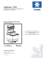
Intellicarb™ 2323 IC2323 Drop-In Ice Cooled 6 & 8 Valve Dispensers with McCann Carbonator Tank INSTALLATION & SERVICE GUIDE Part Number 020000803 Notice: DO NOT throw this manual away. This manual contains important information regarding this product. Keep this manual at the dispenser location. Manitowoc Beverage Equipment 2100 Future Drive Sellersburg, IN 47172-1868 Tel: 812.246.7000, 800.367.4233 Fax: 812.246.9922 www.manitowocbeverage.com In accordance with our policy of continuous product development and improvement, this information is subject to change at any time without notice. May 31, 2007 REV2 FOREWORD Manitowoc Beverage Equipment (MBE) developed this manual as a reference guide for the owner/ operator, service agent, and installer of this equipment. Please read this manual before installation or operation of the machine. A qualified service technician should perform installation and startup of this equipment, consult the Troubleshooting Guide within this manual for service assistance. If you cannot correct the service problem, call your Pepsi Service Representative or Distributor. Always have your model and serial number available when you call. Model Number ______________________________________________________________________ Serial Number _______________________________________________________________________ Installation Date _____________________________________________________________________ Your Local Pepsi Service Telephone Number _____________________________________________ UNPACKING AND INSPECTION Note: The unit was thoroughly inspected before leaving the factory. Any damage or irregularities should be noted at the time of delivery (or not later than 15 days from the date of delivery.) WARRANTY INFORMATION Consult Manitowoc Beverage Equipment for terms and conditions of your warranty. Your warranty specifically excludes all beverage valve brixing, general adjustments, cleaning, accessories and related servicing. Your warranty card must be returned to Manitowoc Beverage Equipment to activate the warranty on this equipment. If a warranty card is not returned, the warranty period can begin when the equipment leaves the MBE factory. No equipment may be returned to Manitowoc Beverage Equipment without a written Return Goods Authorization (RGA). Equipment returned without an RGA will be refused at MBE’s dock and returned to the sender at the sender’s expense. Please contact your local Manitowoc distributor for return procedures. Installation and Service Manual TABLE OF CONTENTS FOREWORD ........................................................................................................ 2 UNPACKING AND INSPECTION ......................................................................... 2 WARRANTY INFORMATION ............................................................................... 2 SAFETY ............................................................................................................... 5 IMPORTANT SAFETY INSTRUCTIONS ........................................................................... 5 QUALIFIED SERVICE PERSONNEL ................................................................................ 5 SHIPPING, STORAGE, AND RELOCATION ..................................................................... 5 INSTALLATION WARNING .............................................................................................. 5 CARBON DIOXIDE WARNING ......................................................................................... 5 ADDITIONAL WARNINGS ................................................................................................ 5 GROUNDING IN STRUCTIONS ........................................................................................ 6 INSTALLATION .................................................................................................... 7 STARTING YOUR BEVERAGE SYSTEM AND DISPENSER ............................................ 7 UNIT INSPECTION ........................................................................................................... 7 PREPARATION & INSTALLATION ................................................................................... 7 WATER, CO2, DRAIN & ELECTRICAL CONNECTIONS .................................................. 8 PURGING AIR FROM THE CARBONATOR TANK .......................................................... 8 PRESSURE RELIEF VALVE TUBING .............................................................................. 9 OPERATION SETUP ........................................................................................................ 9 6 VALVE ......................................................................................................................... 10 8 VALVE ..........................................................................................................................11 OPERATION ...................................................................................................... 12 SPECIFICATIONS .......................................................................................................... 12 BACK ROOM PACKAGE ............................................................................................... 13 PUMP ............................................................................................................................. 13 USER MAINTENANCE ...................................................................................... 14 DISASSEMBLE FOR CLEANING ................................................................................... 14 DAILY CLEANING .......................................................................................................... 14 WEEKLY CLEANING ...................................................................................................... 14 MONTHLY CLEANING ................................................................................................... 15 QUARTERLY CLEANING - BAG-IN-BOX SYSTEM ....................................................... 15 HOW TO ACCESS THE LIQUID LEVEL CONTROL & FLOAT ....................................... 16 PREVENTATIVE MAINTENANCE .................................................................................. 16 3 Installation and Service Manual TABLE OF CONTENTS EXPLODED VIEWS, PARTS & DIAGRAMS ..................................................... 17 PUMP DECK .................................................................................................................. 17 LIGHT BOX .................................................................................................................... 17 IC2323 6 & 8 VALVE EXPLODED VIEW ......................................................................... 18 IC2323 6 & 8 VALVE PARTS LIST .................................................................................. 19 IC2323 6 VALVE ONLY PARTS LIST .............................................................................. 19 CARBONATOR TANK / BAFFLE ASSEMBLY ............................................................... 20 115V MERCHANDISER .................................................................................................. 21 220/240V MERCHANDISER ........................................................................................... 21 115V WIRING DIAGRAM ................................................................................................ 22 220/240V WIRING DIAGRAM ......................................................................................... 22 TROUBLESHOOTING ....................................................................................... 23 PUMP ............................................................................................................................. 24 INDEX................................................................................................................. 27 4 Installation and Service Manual SAFETY IMPORTANT SAFETY INSTRUCTIONS Carefully read all safety messages in this manual. Learn how to operate the Intellicarb™ 2323 properly. Do not allow anyone to operate the unit without proper training and keep it in proper working condition. Unauthorized modifications to the Intellicarb™ 2323 may impair function and/or safety and affect the life of the unit. CARBON DIOXIDE WARNING DANGER: Carbon Dioxide (CO2) displaces oxygen. Exposure to a high concentration of CO2 gas causes tremors, which are followed rapidly by loss of consciousness and suffocation. If a CO2 gas leak is suspected, particularly in a small area, immediately ventilate the area before repairing the leak. CO2 lines and pumps should not be installed in an enclosed space. An enclosed space can be a cooler or small room or closet. This may include convenience stores with glass door self serve coolers. If you suspect CO2 may build up in an area, venting of the B-I-B pumps and / or CO2 monitors should be utilized. QUALIFIED SERVICE PERSONNEL WARNING: Only trained and certified electrical and plumbing technicians should service this unit. All wiring and plumbing must conform to national and local codes. SHIPPING, STORAGE, AND RELOCATION CAUTION: Before shipping, storing, or relocating this unit, syrup systems must be sanitized. After sanitizing, all liquids (sanitizing solution and water) must be purged from the unit. A freezing environment causes residual sanitizing solution or water remaining inside the unit to freeze, resulting in damage to internal components. INSTALLATION WARNING WARNING: The splash panel must remain in place for installation because the splash panel provides structural integrity to the unit. Do not remove the splash panel until after the unit is installed. ADDITIONAL WARNINGS Installation and start-up of this equipment should be done by a qualified service technician. Operation, maintenance, and cleaning information in this manual are provided for the user/operator of the equipment. Save these instructions. 5 Installation and Service Manual SAFETY GROUNDING IN STRUCTIONS WARNING: Risk of electrical shock. Connect to a properly grounded outlet only. This appliance must be grounded. In the event of malfunction or breakdown, grounding provides a path of least resistance for electric current to reduce the risk of electric shock. This appliance is equipped with a cord having an equipment-grounding conductor and a grounding plug. The plug must be plugged into an appropriate outlet that is properly installed and grounded in accordance with all local codes and ordinances. DANGER – Improper connection of the equipment-grounding conductor can result in a risk of electric shock. The conductor with insulation having an outer surface that is green with or without yellow stripes is the equipment grounding conductor. If repair or replacement of the cord or plug is necessary, do not connect the equipment-grounding conductor to a live terminal. Check with a qualified electrician or serviceman if the grounding instructions are not completely understood, or if in doubt as to whether the appliance is properly grounded. Do not modify the plug provided with the appliance – if it will not fit the outlet, have a proper outlet installed by a qualified electrician. WARNING – When using electric appliances, basic precautions should always be followed, including the following: a) Read all the instructions before using the appliance. b) To reduce he risk of injury, close supervision is necessary when an appliance is used near children. c) Do not contact moving parts. d) Only use attachments recommended or sold by the manufacturer. e) Do not use outdoors. f) For a cord-connected appliance, the following shall be included: • Do not unplug by pulling on cord. To unplug, grasp the plug, not the cord. • Unplug from outlet when not in use and before servicing or cleaning. • Do not operate any appliance with a damaged cord or plug, or after the appliance malfunctions or is dropped or damaged in any manner. Return appliance to the nearest authorized service facility for examination, repair, or electrical or mechanical adjustment. g) For a permanently connected appliance – Turn the power switch to the off position when the appliance is not in use and before servicing or cleaning. h) For an appliance with a replaceable lamp – always unplug before replacing the lamp. Replace the bulb with the same type. i) For a grounded appliance – Connect to a properly grounded outlet only. See Grounding Instructions. SAVE THESE INSTRUCTIONS 6 Installation and Service Manual INSTALLATION STARTING YOUR BEVERAGE SYSTEM AND DISPENSER Upon completion of the beverage dispenser and / or system installation, all tubing, dispenser, and system components must be cleaned and sanitized prior to use. NOTE: At installation equipment, dispensers, and tubing get moved through many environments, dirt, dust, chases, insulation, drywall, etc. It is an important procedure and best practice to address cleaning to deliver the best quality drink to your customer. Clean and sanitize the water and syrup circuits according to instructions provided in this manual. Clean and sanitize the dispenser components according to instructions provided in this manual. Consult and use local health codes if a discrepancy occurs between this manual and your local health codes. UNIT INSPECTION Thoroughly inspect the unit upon delivery. Immediately report any damage that occurred during transportation to the delivery carrier. Request a written inspection report from a claims inspector to document any necessary claim. Inspect the accessories to make sure the following components are included: Component Quantity Part Number Power supply kit 1 5030679 Insulated tubing (6 feet) 2 1200417 Valve decals 1 5008376 Installation and service manual 1 5029794 Water regulator 50 PSI 1 5011794 Drain strainer 1 5013878 Pump deck with 75 PSI CO2 regulator 1 5031856 PREPARATION & INSTALLATION ™ The Intellicarb 2323 can be installed in a counter or in a freestanding cabinet. To install the unit in a counter, make sure you have a flat, level counter that is at least 23.25 inches × 23.25 inches and that will support 249 lbs. Also consider the location of the following items before installation: • Water line • Power outlet • Drain • Heating and air conditioning ducts 1. If installing the unit in a counter, first mark the location of the hole in the counter. Cut out the hole in the counter. CAUTION: The unit must be sealed to the counter to comply with the National Sanitation Foundation requirements. 2. Liberally apply a sealant (e.g., Dow Corning RTV 731) to the bottom surface of the flange on the unit. WARNING: The splash panel must be in place before lifting the unit into the counter or freestanding cabinet. 3. Lower the unit into the hole in the counter or freestanding cabinet. 4. Apply additional sealant around the rim of the unit to ensure a complete seal. Remove any excess sealant. 7 Installation and Service Manual INSTALLATION WATER, CO2, DRAIN & ELECTRICAL CONNECTIONS Follow steps 1 through 12 to make the water, CO2, drain and electrical connections. (See the illustration below for added assistance.) Note: If the water supply to the unit, or pump deck is above 50 PSI you must install the 3/8 barb x 3/8 barb 50 PSI in line water regulator that was provided with the unit. 1. Connect the incoming water line to the remote carbonator pump deck inlet barb. 2. Connect the carbonated water line from the remote carbonator pump deck to the inlet barb on the unit. 3. Connect the noncarbonated water line to the inlet barb on the unit. 4. Connect syrup lines from BIB pumps to barbed cold plate syrup inlets. 8. Connect the incoming CO2 line from the remote carbonator regulator to the carbonator inlet barb on the unit (75 PSI). DO NOT turn on CO2 supply at this time. NOTE: Connect the other CO2 line from the primary regulator to the BIB manifold located on the BIB rack (60 PSI). 9. Set Flex Manifold to desired settings (carbonated or non-carbonated) (See Plumbing Diagram in Recommended Plumbing) 10. Turn on the water supply. (See "Purge air from 5. Connect the insulated hose to the drain pan fitting. Run hose to drain. 6. Connect the insulated hose to the cold plate drain fitting. Run hose to drain and add ice to the ice bin. 7. Connect the CO2 line from the primary 105 lb regulator to the inlet barb of the regulator, on the carbonator pump deck. 11. Plug the low-voltage wiring into the Class 2 power supply. Plug the power supply into a 115v electrical outlet. 12. Plug the power cord (from the carbonator pump) into the unit power cord assembly. NOTE: The water must be turned on before plugging the power cord in. carbonator tank" below) PURGING AIR FROM THE CARBONATOR TANK 1. Plumb unit as described in steps 1 - 8. Do not energize the unit. Do not turn on the CO2 to the unit. 4. Follow the instructions in the manual for energizing the unit. 2. Remove the splash panel and open the vent on the carbonator pressure relief valve. 5. Operate any valve to remove all the air from the water lines. 3. Turn on the water to the unit and fill the carbonator with water. Close the vent on the carbonator pressure relief valve when water begins to escape. Follow instructions in the manual for remaining unit set up. 8 Installation and Service Manual INSTALLATION PRESSURE RELIEF VALVE TUBING The internal carbonator tank in the Intellicarb™ 2323 uses a 125psi pressure relief valve that must be vented into a nearby drain connection. Follow the steps below for installation of the pressure relief valve tubing. 1. Turn off the key switch located on the side of the tower (right or left side depending on your unit). 2. Lift out the cup grid. 3. Remove the splash panel by pulling it toward you. 4. Locate the internal carbonator tank, and ¼” tubing supplied with unit. (Both will be located behind the splash panel) 5. Unroll the tubing and assure one end of the tubing is attached to the ¼” barb fitting on the 125psi pressure relief valve located on the carbonator tank. (See Figure 1-A) B A FIGURE 1 6. Route the other end of the tubing through the cutout where the beverage lines come out of the bin. (See Figure 1-B) 7. To route tubing out of unit, remove the screws from the back panel and route tubing as shown. (See Figure 2). 8. Assure all excess tubing is out of unit and replace back panel by securing with the screws that were removed in step 7. 9. Attach ¼” tubing to drain connection. 10. Replace splash panel, cup grid and turn the key switch back to the "ON" position. Note: Plumbing must conform to national and local codes. FIGURE 2 OPERATION SETUP After all of the connections are made, take the following steps to turn on the Intellicarb™ 2323: 1. Make sure to plug in the low-voltage power supply (see step 11, Water, CO2, Drain & Electrical Connections). 2. Activate any valve to remove all of the air from the water line. 3. Turn on the CO2 supply. 4. Adjust the water-to-syrup ratio (brix) for each valve (Not necessary if equipped with Pepsi Intellivalves) 9 Installation and Service Manual INSTALLATION 6 VALVE The 6 valve Intellicarb™ 2323 is manufactured with a Flexible Manifold that allows you to change valves 5-6, 4, 3, 1-2 from carbonated to non-carbonated water by making a simple adjustment. (See example below) NOTES: • • 10 A check valve must be installed to the noncarbonated water connection "PW". Contact factory if not installed. Valves read from right to left. • For making adjustments to the Flex Manifold use the 90o 5/32 allen wrench (5029218) supplied with the unit. Installation and Service Manual INSTALLATION 8 VALVE The 8 valve Intellicarb™ 2323 is manufactured with a Flexible Manifold that allows you to change valves 3, 4, 5 and 6 from carbonated to non-carbonated water by making a simple adjustment. (See example below) Valves 1, 2, 7 and 8 are all plumbed for carbonated water only. NOTES: • • A check valve must be installed to the noncarbonated water connection "PW". Contact factory if not installed. Valves read from right to left. • For making adjustments to the Flex Manifold use the 90o 5/32 allen wrench (5029218) supplied with the unit. 11 Installation and Service Manual OPERATION The Intellicarb™ 2323 is a beverage dispensing unit. Unlike many other beverage dispensing units, the Intellicarb™ 2323 is modular. The modular construction provides flexibility for installation and servicing. The tower of the Intellicarb™ 2323 is constructed of durable stainless steel. The unit may be placed in a counter or in a freestanding cabinet. The Intellicarb™ 2323 is equipped with a remote Procon® carbonator pump and a Class 2 power supply that supplies the unit with 24 volts to power the beverage dispensing valves. SPECIFICATIONS Measurement Stainless Steel Units Counter cutout 23.25" × 23.25" Height above counter 25" Width 23.0" Depth 23.0" Height 48" Ice bin capacity 80 lbs. Weight of the unit 169 lbs. Electrical Specs 120v 60Hz 12FLA LINES 10 9 8 7 6 5 4 3 2 1 12 Line Type 1 Syrup 2 Syrup 3 Syrup 4 Syrup 5 Syrup 6 Syrup 7 Syrup 8 Syrup 9 Non-carbonated Water Inlet 10 Water Inlet from Carbonator Pump Installation and Service Manual OPERATION BACK ROOM PACKAGE PUMP 13 Installation and Service Manual USER MAINTENANCE DISASSEMBLE FOR CLEANING A B A. Turn off the key switch located on the side of the tower (right or left side depending on your unit). C B. Lift out the cup grid. C. Remove the splash panel by pulling it toward you. D D. Lift the drain pan straight up and pull it out. E. Remove the ice bin cover. CLEANING CHECKLIST E • Check CO2 supply. If CO2 supply is low, an arrow on the primary regulator gauge will point to a shaded area that reads “Low CO2” or “Change CO2 Cylinder.” • Check syrup supply. • Clean drain pan, grid, and splash panel. (See below) • Clean the valve nozzles and diffusers. (See below) DAILY CLEANING All cleaning must meet your local health department regulations. The following cleaning instructions are provided as a guide. CAUTION: Use only warm soapy water to clean the exterior of the unit. Do not use solvents or other cleaning agents. Clean the exterior of the Intellicarb™ 2323: 1. Turn off the key switch located on the left side of the tower. 2. Clean the cup grid, splash panel, and drain pan with a sponge and mild detergent mixed with warm (100 °F) water. Rinse with clean water. 3. Wipe the exterior of the tower with a clean, damp cloth. 4. Turn on the key switch. WEEKLY CLEANING Clean the dispensing valves: 1. Turn off the key switch located on the left side of the tower. 2. Remove the valve covers, syrup diffusers, and nozzles and wash with a small, round nylon 14 bristle brush and warm (100 °F) water. 3. Reinstall the nozzles, syrup diffusers, and valve covers. 4. Turn on the key switch. Installation and Service Manual USER MAINTENANCE MONTHLY CLEANING Clean and sanitize the ice bin and cold plate: 1. Remove all ice from the ice bin. 2. Remove the ice bin strainer by lifting it straight up. 3. Prepare a mild detergent solution using warm (100 °F) water. 4. Wash the ice bin using a sponge and the mild detergent solution. 5. Wash the cold plate using a soft, nylon bristle brush and the mild detergent solution. 6. Pour the remaining detergent solution in the drain pan and watch for obstruction of flow. 7. Rinse the ice bin and cold plate with clean water. 8. Prepare 2 gallons of sanitizing solution by mixing 1 ounce of household bleach (that contains 5.25% sodium hypochlorite) with 2 gallons of 120 °F water. The mixture should not exceed 200PPM of chlorine. 9. Sanitize the ice bin and cold plate with the sanitizing solution for at least 10 seconds. 10. Allow to air dry. Do not rinse. QUARTERLY CLEANING - BAG-IN-BOX SYSTEM The procedure below is for the sanitation of one syrup circuit at a time. Repeat to sanitize additional circuits. You will need the following items to clean and sanitize the Bag-in-Box (BIB) beverage system: • Three (3) clean buckets • Plastic brush or soft cloth • Mild detergent • Unscented bleach (5% Na CL O) or Commercial sanitizer • Bag-In-Box bag connector 1. Prepare the following in the buckets: • Bucket 1 - warm to hot tap water for rinsing. • Bucket 2 - mild detergent and warm to hot water. • Bucket 3 - mix a solution of unscented bleach (5% Na CL O) or commercial sanitizer and warm to hot water. Mixture should supply 200PPM available chlorine (1/2 oz. bleach to 1 gallon water). 2. Disconnect the “syrup-line side” of the bag-in-box connector. (See Figure 1 Below) 3. Rinse connector with warm tap water. 4. Connect syrup connector to BIB connector and immerse both into Bucket 1. A “bag-side” connector can be created by cutting the connector from an empty disposable syrup bag (See Figure 1 Below). 5. Draw rinse water through system until clean water is dispensed. Most beverage valves allow the syrup side to be manually activated by depressing the syrup pallet. 6. Connect Bucket 2 to system. 7. Draw detergent solution through system until solution is dispensed. 8. Repeat steps 2-7 until all syrup circuits contain detergent solution. 9. Allow detergent solution to remain in the system for 5 minutes. 10. Connect Bucket 3 to system. 11. Draw sanitizing solution through system until solution is dispensed. 12. Repeat step 11 until all syrup circuits contain sanitizer solution. 13. Allow sanitizer solution to remain in system for 15 minutes. 14. Remove nozzles and diffusers from beverage valves. 15. Scrub nozzles, diffusers and all removable valve parts (except electrical parts) with a plastic brush or a soft cloth and the detergent solution. 16. Soak nozzles, diffusers and removable valve parts (except electrical parts) in sanitizer for 15 minutes. 17. Replace nozzles, diffusers and valve parts. 18. Connect Bucket 1 to system. 19. Draw rinse water through system until no presence of sanitizer is detected. 20. Attach syrup connectors to BIB’s. 21. Draw syrup through system until only syrup is dispensed. 22. Discard first 2 drinks. FIGURE 1 15 Installation and Service Manual USER MAINTENANCE WARNING: Be sure to unplug power cord before servicing the Intellicarb™ 2323. It is a shock hazard if left plugged in and operation of motors without water may damage components. HOW TO ACCESS THE LIQUID LEVEL CONTROL & FLOAT 1. First, unplug the unit power cord from the wall outlet (unit and pump deck power will be eliminated by doing so). Then shut off the water and CO2. 2. Remove the cup grid, splash panel, drain pan and ice bin cover. (See the Disassemble for Cleaning section) 3. Disconnect the carb tank probe connection. 2 4. Activate the relief valve to release CO2. 5. Remove the three screws in the top of the carbonator. 6. Lift out the liquid level control. 7. Remove the three hex nuts in the liquid level float assembly. 8. Lift out the liquid level float assembly. See the Disassemble for Cleaning section 3 5 6 1 7 4 NOTE: 8 Make sure the carbonator power cord is facing the back of the Intellicarb™ 2323 when the liquid level control is reinserted. PREVENTATIVE MAINTENANCE Preventative maintenance is a vital part of keeping your MII dispenser in top condition. Following the guidelines below will assist you in continued trouble free operation of your unit. 1. Conduct daily maintenance of the machine. 2. Perform monthly maintenance of the machine. 3. Perform periodic maintenance and sanitizing of beverage system. 4. Do not overfill the dispenser bin with ice. 5. Do not allow the dispenser to sit for prolonged periods of non use with ice in the bin. 6. Most ice dispenser service problems are caused by low usage of the ice dispenser. 7. Do not allow ice to remain in the bin more than a day in order to prevent ice from freezing together and/or stagnant ice. 16 Possible excess ice storage reasons: • Storage capacity exceeds daily requirements. • Low demand during the off season. • Dispenser oversized with future growth in mind. Lower ice storage to meet one day’s needs. If you manually fill ice, fill only with the appropriate amount of ice. Fill the dispenser with fresh ice each morning. Do not fill the dispenser at night just before shut down. Ice cubes can freeze together if not dispensed. Contact MBE at 1-800-367-4233 for more information about our ProActive Maintenance Program. Installation and Service Manual EXPLODED VIEWS, PARTS & DIAGRAMS PUMP DECK LIGHT BOX 15 10 6 11 8 1 12 14 3 16 2 5 No Part # Description 1 0901915 WASHER STAR #8 SS 2 0905403 CLIP PLASTIC WIRE & CORD 3 1000309 TUBE FLORESCENT 4 1001001 SOCKET END LIGHT 5 1001005 STARTER LEV FS2 6 1200301 PLUG HEYCO CORD STRAIN RELIEF 7 5000974 SCREW 8-32 X 1 1/4" PH PS 8 5008415 WIRING HARNESS IC2323 LB 9 5008416 BRACKET 10 5008642 CORD ELECTRIC 11 5008644 BALLAST 12 5011936 SCREW 8-32 X 1/2 GRND ZINC 13 5011940 SCREW 8-32 X 1/2 14 20001620 MEDALLION PEPSI LIGHT BOX 15 20001623 CAP LIGHT BOX 16 20001635 BOX LIGHT WELDED 7 4 13 9 17 Installation and Service Manual EXPLODED VIEWS, PARTS & DIAGRAMS IC2323 6 & 8 VALVE EXPLODED VIEW 18 Installation and Service Manual EXPLODED VIEWS, PARTS & DIAGRAMS IC2323 6 & 8 VALVE PARTS LIST No. 1 2 3 4 5 6 7 8 9 10 11 12 13 14 15 16 17 18 19 20 21 22 23 24 Part Number 1200322 5000220 5009298 5010332 5013687 5028059 5029327 5029328 5029329 5029539 5029632 5029633 5029638 5029734 5029735 5029742 5029743 5029783 5029785 5029787 5029844 5029892 5029893 5030191 Description PLUG-D HEYCO 2503 KEYSWITCH NIPPLE 3/4 X 2-1/4 SLIPON INSUL MANIFOLD INT CARB ELBOW, 45 DEG. 1/4" BARB INLET INSUL 1/4 X 2-1/4 BASE IC 2323 BIN ICE BLK COLDPLATE NPT BARB PLATE VLV MNTG 8 VLV WRAP TOWER PANEL SPLASH DOOR TAB COVER ICE BIN GSKT RETAINING FOAM GSKT RETAINING FOAM CAP TOWER LIGHT KIT TUBE DRAINPAN GSKT RETAINING FOAM CARB WATER MANIFOLD PLAIN WATER MANIFOLD LINE POSTCHILL VLV 3&6 No. 25 26 27 28 29 30 31 32 33 34 35 36 37 38 39 40 Part Number 5030192 5030556 5030557 5031650 5031856 5031857 020000251 020000986 020000989 020000992 020001036 020001037 5013849 5013850 5013864 VLV 0901805 5011953 5013883 5029797 5011794 5013878 5011377 Description LINE POSTCHILL VLV 4&5 TUBE CARBONATOR OUTLET TUBE CARBONATOR INTLET POWER SUPPLY DECK 115V PUMP VB DECK 220V PUMP VB WRAP WELDED BEZEL MANIFOLD 4 PORT RAISED PLATE MANIFOLD MTG SCR 8-32 X 4/8 T410SS HH TRI-LOBE TANK CARB 115V TANK CARB 220V COVER REAR DRAINPAN BLACK CUP GRID (OPTIONAL GRID ACCUFILL #5013865) SEE BOM WASHER FLAT 1/4" SS SCR 10-24 X 1-1/4 SELF TAP CORD POWER BOLT HEX 1/4-20 X 5.000 REG WTR 50 PSI DRAIN STRAINER VLV DBL CHK 3/8 HB X 3/8 HB IC2323 6 VALVE ONLY PARTS LIST No. 1 2 3 Part Number 5008239 5030836 5031413 Description LINE MANIFOLD OUT 1/4" MANIFOLD PLAIN WATER PLATE VLV MNTG 6 VLV No. 4 5 6 Part Number 5031505 5031507 5031509 Description CARB WTR MANIFOLD 6 VLV MANIFOLD 2 VLV LINE POST CHILL 3 & 4 19 Installation and Service Manual EXPLODED VIEWS, PARTS & DIAGRAMS CARBONATOR TANK / BAFFLE ASSEMBLY 20 ITEM PART # DESCRIPTION 1 16-2115-41 ASSY. PROBE 115V ELECTRICAL, BLACK CAP, SOLENOID DRIVING, SPARE PARTS KIT FOR PROBE IS 16-1404. 2 09-1877 STUD, PROBE 3 15-1951 ASSY, 115V/220V, PROBE, FLOAT RING. 4 5030390 VALVE PRESSURE RELIEF 125 PSI W/BARB 5 00701312 CHECK VALVE, CARBONATOR, SINGLE 1/4 MALE FLARE. 6 19-0934 FITTING, .125NPT X PRV, S.S. ADAPTER. 7 15-3119 ASSY CARBONATOR 10" WELD COMPLETE 8 1701115 WASHER, 3/8 IN. NYLON WHITE. 9 1701110 NUT, 3/8 X 9/16 IN. SWIVEL FTG. 10 5009025 FITTING, 1/4 IN. SWIVEL 3/8 BARB. 11 1701113 WASHER, 1/4 IN. NYLON WHITE. 12 1701109 FITTING, 1/4 IN. SWIVEL HOSE BARB. 13 1701108 NUT, 1/4 X 3/8 IN. SWIVEL FTTG. 14 16-2226-41 ASSY. PROBE 220V ELECTRICAL 50/60HZ BLACK CAP, SOLENOID DRIVING, SPARE PARTS KIT FOR PROBE IS 16-1406. 15 5031855 INSUL DOMED CARB Installation and Service Manual EXPLODED VIEWS, PARTS & DIAGRAMS 115V MERCHANDISER 220/240V MERCHANDISER 21 Installation and Service Manual EXPLODED VIEWS, PARTS & DIAGRAMS 115V WIRING DIAGRAM 220/240V WIRING DIAGRAM 22 Installation and Service Manual TROUBLESHOOTING PROBLEM SOLUTION Beverages do not dispense. Make sure the low-voltage power supply (transformer) is plugged into an electrical outlet . (Step 11, Water, CO2, Drain & Electrical Connections) Make sure the key switch (found on either the left or right side of the tower) is turned on. Make sure the CO2 supply is turned on. The carbonator pump does not work. Make sure the carbonator power cord is plugged into an electrical outlet. (Step 12, Water, CO2, Drain & Electrical Connections) Make sure the water supply and pressure is turned on. Make sure the carbonator power supply is plugged in (behind the splash panel). (Step 3, How to Access the Liquid Level Control & Float) Check the carbonator pump and replace if necessary. (See How to Access the Liquid Level Control & Float) Check the liquid level float and replace if necessary. The carbonator gases out. Clean, service, or replace the liquid level float. (See How to Access the Liquid Level Control & Float) Check water supply and pressure (min 40psi - max 55 psi). The pressure relief valve opens. Clean, service, or replace the liquid level float. (See How to Access the Liquid Level Control & Float) Check water supply and pressure (min 40psi - max 55 psi). The beverages are too sweet. Make sure the CO2 supply is turned on. Brix the valves. (Flomatic valve brixing) The beverages are not sweet enough. Check to see if the BIB is empty and replace if necessary. Adjust the water-to-syrup ratio (brix). (Flomatic valve brixing) The beverages are not cold. Fill the ice bin. The carbonator pump will not shut off. Repair any leaks in the carbonated water system. Check the liquid level float and replace if necessary. (See How to Access the Liquid Level Control & Float) The carbonator cycles erratically. Replace the liquid level float or the liquid level control. The carbonator pump capacity is too low. Remove any kinks in the water supply line. Check water supply and pressure (min 40psi - max 55 psi). Make sure the water supply is turned on and the valve is fully opened. The carbonator pump operates but does not pump water. Make sure the water supply is adequate (minimum 40 PSI). Replace the carbonator pump if necessary. Water leaking from bin/base seam or out back of unit Check drain, unstop bin drain or drain tubing. 23 Installation and Service Manual TROUBLESHOOTING PUMP PROBLEM POSSIBLE CAUSE Pump motor does not shut off. Problem with probe or probe harness. Pump motor intermittent Problem with probe or probe harness. 24 CORRECTIVE ACTION 1. Remove Probe Electronics 2. Pass Magnetic Tip of Screwdriver by Lower end of Tube Extending from Electronics Package 3. Reed Switch Closes 4. Carbonator Operates Installation and Service Manual 25 Installation and Service Manual INDEX Symbols E N 105 lb regulator ......................... 8 A electrical outlet .......................... 8 Exploded Views .. 19, 20, 21, 22 exterior .................................... 14 accessories ............................... 7 non-carbonated ............ 8, 10, 11 Notes ..................... 8, 10, 11, 16 nozzles .................................... 15 NSF ........................................... 6 F B flange ........................................ 7 Flexible Manifold .......... 8, 10, 11 Float ................................. 16, 23 FOREWORD ............................ 2 freestanding cabinet ............ 6, 7 B-I-B ........................................ 15 Back Room Package .............. 13 Baffle Assembly ...................... 20 BIB manifold ............................. 8 BIB Rack ................................... 8 brixing ....................................... 2 C Operation .................................. 5 Operation Setup ........................ 9 outlet ....................................... 16 servicing .................................. 16 Shipping .................................... 5 Shipping, Storage, Relocation .. 5 shock hazard .......................... 16 soapy water ............................. 15 solvents ................................... 15 Specifications .......................... 12 splash panel ....................... 4, 14 start-up ...................................... 5 Storage ..................................... 5 P T Parts .................... 19, 20, 21, 22 Pepsi Service ............................ 2 power cord .............................. 16 Power outlet .............................. 7 power supply .................. 8, 9, 12 Preparation & Installation .......... 7 Procon® .................................. 12 Pump ....................................... 13 pump deck ................................ 8 TROUBLESHOOTING ..... 23, 24 O H health department ................... 14 hose .......................................... 8 Carbon Dioxide ......................... 5 carbonated ........................ 10, 11 carbonator .......................... 8, 16 carbonator pump ..................... 12 Carbonator Tank ..................... 20 CAUTION ........................... 6, 15 claims ........................................ 7 Cleaning ............................. 2, 14 CO2 ...................................... 4, 8 CO2 monitors ............................ 4 cold plate ................................ 15 components .............................. 7 connections .................... 8, 9, 23 cup grid ................................... 14 I D L damage ................................ 2, 7 delivery ................................. 2, 7 detergent ................................. 15 Diagrams ............ 19, 20, 21, 22 diffusers ........................... 14, 15 Disassemble .................... 14, 16 dispensing valves ................... 14 distributor .................................. 2 Dow Corning RTV 731 .............. 7 Drain ......................................... 7 drain pan ................................. 14 drain pan fitting ......................... 8 ducts ......................................... 7 Lines ....................................... 12 Liquid Level Control ......... 16, 23 liquid level float ....................... 16 location ..................................... 7 low-voltage ................................ 9 ice bin ................................. 8, 15 ice bin cover ............................ 14 inlet barb ................................... 8 INSPECTION ............................ 2 INSTALLATION .. 7, 8, 9, 10, 11 Installation Date ........................ 2 Instructions ............................. 14 irregularities .............................. 2 V valve covers ............................ 14 valve nozzles .......................... 15 valves ........................... 9, 10, 11 Qualified Service Personnel ..... 5 Quarterly Cleaning .................. 15 W R key switch ............................... 14 regulations .............................. 14 regulator .................................... 8 Relocation ................................. 5 remote carbonator .................... 8 requirements ............................. 6 return procedures ..................... 2 MBE .......................................... 2 Model Number .......................... 2 Monthly Cleaning .................... 15 Unit Inspection .......................... 7 UNPACKING ............................. 2 Q K M U S SAFETY ............................... 5, sanitizing ................................... sealant ...................................... Serial Number ........................... service assistance .................... Service Personnel ..................... WARNING .......................... 6, 16 Warning ..................................... 5 WARRANTY INFORMATION ... 2 Water ............................. 8, 9, 23 Water line .................................. 7 water line ................................... 9 water-to-syrup ratio .. 9. See also brixing Weekly Cleaning ..................... 14 Wiring Diagrams ..................... 22 6 4 7 2 2 5 27 Manitowoc Beverage Equipment 2100 Future Drive Sellersburg, IN 47172-1868 Tel: 812.246.7000, 800.367.4233 Fax: 812.246.9922 www.manitowocbeverage.com In accordance with our policy of continuous product development and improvement, this information is subject to change at any time without notice. 020000803 May 31, 2007 REV2