1
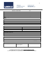
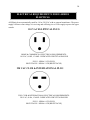
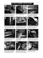
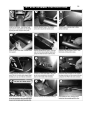
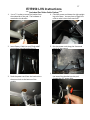
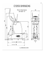
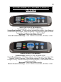
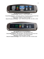
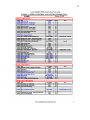
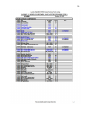
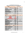
1
LANDICE, INC.
111 CANFIELD RD., SUITE A-1
RANDOLPH, NJ 07869
PHONE: (973) 927-9010
FAX: (973) 927-0630
[email protected]
ELLIPTICAL E7 / E950
HOME & COMMERCIAL
SERVICE MANUAL
Starting with Serial #
E010004
Version 3.2
For Technical Service Call 1-(800)-LANDICE, Ext. 170
EMAIL: [email protected]
8-31-15
2
Table of Contents
Service Manual Version 3.2
Pages 2-3……………………..Table of Contents
SECTION 1 –WARRANTY INFORMATION
Pages 4-8..………………..…..Replica WTY Cards & Warranty Policies
Page 9……………………...…Service Authorization Claim Form
SECTION 2 - INSTALLATION
Page 10……………………….Tools needed for Installation and Repair
Pages 11-13...............................Safety Instructions
Page 14……………………….Electrical Requirements for E-Series Elliptical
Page 15-18……………………Assembly Instructions
SECTION 3 – PARTS IDENTIFICATION
Page 19………………………..E-Series Elliptical Dimensions & Weight
Pages 20-21……………………E-Series Control Panels and Features
Page 22………………………..Accessing Diagnostic Features on Elliptical Consoles
Pages 23-26……………………Definition of Parts
SECTION 4 – SERVICING LANDICE ELLIPTICALS
Pages 27-29…………………….Testing Components
Pages 30….…………………….Relay board, LED Configuration and Function
Pages 32…….………………….Display Button Feedback
Page 33…………………….….. Membrane Bypass Test
Pages 34-35…………………….Heart Monitor Diagnosis
Pages 36-40…………………….Removal and Replacement of Crankshaft and Frame Bearings
Pages 41-43…………………….Removal and Replacement of Magnet Brake and Brake Cable
Pages 44-45…………………….Removal and Replacement of Brake Motor
Pages 46………………………..Flowchart Section - Use to diagnose common problems
Page 47 ………………………...Flowchart – Unit Won’t Turn On
Page 48…………………………Flowchart – No speed feedback
Page 49…………………………Flowchart- PO error, No Resistance, Error in Brake Controller
Page 50…………………………Wire Schematic
Page 51…………………………Main Wire Harness
Page 52-60...…………………....High-Tech Entertainment Center Diagnostic Addendum.
Page 62…………………………Voltage Readings for High-Tech Center
Page 63…………………………Fan/Speaker not Working
Page 64…………………………Fan will not turn on
Page 65…………………………Fan runs at one speed
Page 66…………………………Display turns on but no sound from speakers
3
SECTION 5- PARTS EXPLOSIONS AND PARTS LIST
Page 67…………………………..Parts Explosion
Page 68………………………..…Frame and Shroud Explosion
Page 69…………………………..Uprights, Contact Heart Rate, Handlebars
Page 70…………………………..Lower Electronics
Page 71…………………………..Stride Components
Page 72…………………………..Crank Arm and Pedal Tubes
Page 73…………………………..Brake Wheel Components
Page 74…………………………..High Tech Center Components
Pages 75-80………………………Parts List
SECTION 6 RETROFITTING LVS
Pages 81-83……………………….Retrofitting Landice LVS to an Elliptical (2nd Generation)
4
5
6
LANDICE WARRANTY AND POLICIES
The Service Warranty covers installation of parts shown to be defective in material or
workmanship. The selling dealer is responsible for labor for ellipticals needing repairs. A Service
Authorization (SA) number must accompany any service reimbursement request. Service
Authorization numbers are given when the selling dealer or the service technician calls Landice
prior to beginning work on the elliptical. This allows Landice to verify that the elliptical is within
the labor warranty and also aids us in helping the technician troubleshoot the elliptical. Landice
welcomes technicians to call us from the field and gives these calls the highest priority.
This Service Warranty does not cover customer instruction, installation, setup, or
maintenance. Line Cords (power cords) are also not covered by this warranty as these can only be
damaged by misuse or abuse.
This warranty does not cover cosmetic damage, damage due to acts of God, accident,
misuse, abuse, or negligence of the product.
The part will be covered in full only if it exhibits
evidence of a manufacturing or material defect during the warranty period. Please keep in mind,
“negligence of the product” includes damage inflicted by using the elliptical in an improper fashion.
7
SERVICE REIMBURSEMENT POLICY:
This is offered to all Landice dealers as well as all authorized Landice service providers.
Landice covers our ellipticals with a 1-year labor reimbursement policy. That means we will pay to
fix our ellipticals as long as it’s within one year from the date the elliptical was purchased.
OUR POLICY:
Landice will reimburse the selling dealer according to our labor rate schedule. If you are a
service provider for Landice and do not sell our product, you have the option of billing us direct or
you can bill the dealer that you are providing service for. Generally, if our capped rate does not
cover your labor charge you would bill the selling dealer. The current rate is $30.00 per hour and is
capped at a maximum of one hour labor and one hour travel per elliptical failure. Diagnostic and
return trips are not covered. If parts were credited out or Invoice was partially paid, the claim will
be denied. Note that set-up procedures are not covered by this warranty.
Set-Up Includes: Assembly, replacing parts due to cosmetic damage or abuse, and
performing any additional adjustments that may have been upset during shipping.
The dealer must call for a service authorization number prior to performing any service to
verify the elliptical is under labor warranty. It is advisable to call Landice from the elliptical
location to successfully diagnose the problem. This will insure that the correct part will be shipped
out the first time. Labor claim forms must be submitted within three months from the date service
was performed. Labor claim forms must be completely filled out and have the Landice Service
Authorization number at the top. Generally service claims are paid out upon the return of defective
parts and/or crediting of the warranty invoice. If parts are outstanding for a period of more than 90
days previously submitted service claims will be returned unpaid.
FLOOR MODELS AND DEALERS STOCK:
If the dealer sells an elliptical to a customer within one year of its purchase from Landice, the
warranty period will be extended to start from the date of sale to the customer. If a residential
elliptical is over 1 year old when sold to a customer, the elliptical will carry a 5 year parts warranty
and there will be NO labor warranty. If a commercial unit is over 1 year old when sold to a
customer, the elliptical will carry the remainder of the parts warranty from the date of shipment
with NO labor warranty.
8
PARTS POLICY
Our policy requires that all defective parts be returned to Landice. All warranty parts will be billed
to the dealer at dealer cost. Landice will credit this invoice upon receipt of defective parts. It is the
dealer's responsibility to return the defective parts to Landice with a copy of the invoice or packing
slip. If the defective parts are not returned within 30 days, payment of invoice is expected in full.
WARRANTY PART ORDERING:
When you order parts under warranty please have the following information available. Warranty
orders cannot be processed without this information:
1) Customer's name, address and phone number
2) Elliptical serial number
3) Detailed description of failure
PURCHASE PART ORDERING:
Serial numbers are recommended to help ensure the correct part is shipped. Purchased parts are
covered by a 90 day replacement part warranty from the date the order shipped.
9
LANDICE, INC.
111 CANFIELD RD., SUITE A-1
RANDOLPH, NJ 07869
SERVICE CLAIM FORM
DEALER INFORMATION:
Service Dealer / Dealer Name:
Address
City
Phone(
Contact
PHONE: (973) 927-9010
FAX: (973) 927-0630
[email protected]
SA#
State
Zip
State
Contact
Zip
)
CUSTOMER INFORMATION
Name
Address
City
Phone(
)
ELLIPTICAL/TREADMILL INFORMATION
Model Type:
Frame Serial #
DCP Serial # (if applicable)
Out of box problem
Yes
No
Date of Service
Date of Purchase
CUSTOMER COMPLAINT
SERVICES PERFORMED/PARTS REPLACED
TRAVEL / LABOR: Travel Time:
Labor Time:
VALIDATION SIGNATURES
Service Rep. Signature
TOTAL TIME: _________
Date
Customer Signature
IN ORDER TO PROCESS THIS CLAIM IN THE LEAST AMOUNT OF TIME,
SEND THE SERVICE CLAIM WITH THE DEFECTIVE WARRANTY PART.
DO NOT SUBMIT SERVICE CLAIMS WITHOUT SERVICE AUTHORIZATION NUMBERS.
10
RECOMMENDED TOOLS FOR SERVICING LANDICE ELLIPTICALS
1. 4-18mm Allen Key socket or wrench set
2. 4-18mm wrenches
3. 3/8 to 7/8 standard socked and wrench set
4. Ratchet & Extension
5. Vise Grips
6. #1, 2, or 3 Phillips Head Screwdriver or power bits
7. #1, 2, or 3 Flat Head Screwdriver or power bits
8. Cordless or Corded Drill
9. Rubber Mallet
10. Diagonal cutters/Dykes
11. Wire Stripper
12. Wire Cutters
13. Digital Multimeter (Analog meters are not recommended)
14. C-Clamp or Pressure clamp (12” span)
15. Snap ring pliers
16. Flat tip punch set
17. Sandpaper
18. Two 12” long 2x4 pieces of wood
11
IMPORTANT OPERATING SAFETY INSTRUCTIONS
WARNING:
Failure to observe the following operating instructions can result in serious
injury!
[1]
If you are suffering from any illness, condition, or disability which affects your ability to run,
walk or exercise, do not use this product without consulting your doctor first.
[2]
If you are suffering from any illness, condition, or disability which affects your ability to run,
walk or exercise, do not use this product without supervision present. Failure to do so may
result in serious injury should you fall while the machine is in motion.
[3]
Failure to leave ample clearance around the elliptical could result in the user becoming
trapped between the mechanism and a wall, resulting in serious injury.
Allow a minimum clearance of 6 inches on each side of the elliptical.
Allow a minimum clearance of 1 foot at the rear of the elliptical.
[4]
Be sure to familiarize yourself with the owner’s manual. Look it over carefully. Be sure you
understand the control panel operation before using the elliptical.
When using an electrical appliance, basic precautions should always be followed. Read all
instructions before using.
DANGER: Always unplug the elliptical before cleaning or removing any shrouds. To reduce
the risk of electrical shock in the event of an electrical storm, always unplug the elliptical
from the electrical outlet after using.
12
IMPORTANT OPERATING SAFETY INSTRUCTIONS
WARNING: To reduce the risk of electrical shock or injuries to persons:
[1]
An appliance should never be left unattended when plugged in. Unplug from outlet when
not in use.
[2]
Close supervision is necessary when this unit is used by or near children or disabled
persons.
[3]
Use this elliptical only for its intended use as described in this manual.
[4]
Never operate this elliptical if it has a damaged cord or plug, if it is not working properly, or
if it has been damaged. Call your selling dealer immediately for examination and repair.
[5]
Keep the power cord away from heated surfaces. Be sure the line cord has plenty of slack
and does not get pinched underneath the elliptical.
[6]
Never drop or insert any object into any opening. Be sure no objects are near or underneath
the elliptical
[7]
Do not operate where aerosol (spray) products are being used or where oxygen is being
administered.
[8]
Connect this appliance to a properly grounded dedicated outlet only.
[9]
To disconnect, press the OFF button, and unplug the unit from the wall outlet.
13
GROUNDING INSTRUCTIONS
This product must be grounded. If it should malfunction or break down, grounding provides a
path of least resistance for electric current to reduce risk of electrical shock. This product is
equipped with a cord having an equipment grounding conductor and a grounding plug. The plug
must be plugged into an outlet that is properly installed and grounded in accordance with all local
codes and ordinances.
120 VOLT ELLIPTICALS
Ellipticals marked 120 VAC are intended for use in a nominal 120-volt circuit with a grounding
plug. Make sure the product is connected to an outlet having the same configuration as the plug.
No adapter should be used with this product.
200 – 250 VOLT ELLIPTICALS
Ellipticals marked 200 – 250 VAC are intended for use on a circuit having a nominal rating more
than 200V and are factory-equipped with a specific cord and plug to permit connection to a proper
electric circuit. Make sure the product is connected to an outlet having the same configuration as
the plug. No adapter should be used with this product. If the product must be reconnected for use
on a different type of electric circuit, qualified service personnel should make the reconnection.
DANGER: Improper connection of the equipment-grounding connector can result in a risk
of electric shock. Check with a qualified electrician or serviceman if you are in doubt as to
whether the product is properly grounded. Do not modify the plug provided with the
product. If it will not fit in the outlet, have a proper outlet installed by a qualified electrician.
14
ELECTRICAL REQUIREMENTS FOR E-SERIES
ELLIPTICAL
All Ellipticals are automatically rated for 110 or 220 VAC with no external transformer. The power
supply will know what voltage it’s receiving and will bring it to a 12Vdc supply to power the upper
console.
110 VAC ELLIPTICAL PLUG
HOME & COMMERCIAL ELECTRICAL REQUIREMENTS:
110 VAC, 60 HZ, 15 AMP - DEDICATED CIRCUIT & GROUND
PLUG - NEMA 5-15P (PLUG)
RECEPTACLE - NEMA 5-15R (RECEPTACLE)
220 VAC CLUB & INTERNATIONAL PLUG
220V CLUB & INTERNATIONAL ELECTRICAL REQUIREMENTS:
220 VAC, 60 Hz, 15 AMP - DEDICATED CIRCUIT & GROUND
PLUG - NEMA 6-15P (PLUG)
RECEPTACLE - NEMA 6-15R (RECEPTACLE)
E7/ E950 ASSEMBLY INSTRUCTIONS
15
E7/ E950 ASSEMBLY INSTRUCTIONS
16
17
E7/E950 LVS Instructions
*** (includes iPod Video Cable Option) ***
1. Use a ½” socket to secure the bracket from
the underside of the pod. The hardware is
attached to the bracket.
4. Feed the power cord down the right upright
leg to the base. You may have to jiggle the
cord to make it thru the access hole.
2. Insert Power, Cable line and *iPod cable*
connections into the back of the TV.
5. Run the power cord along the frame and
rest it on the ground.
3. Feed the power cord from the bracket thru
the access hole at the bottom of the
upright.
6. Feed the cable line and *iPod Cable* from
the base of the bracket into the pod
through the 1¼” access hole.
7. If you have an iPod Cable, then connect the
headphone plug to the available jack on the
inside of pod.
8. If you have an iPod Cable, then feed the
docking connector through the pod and
reinsert the black plastic access cap.
9. Feed the cable line down the left upright leg
thru the access hole at the base.
18
10. Connect the cable line to the inside of the
motor cover before securing it. Then mount
motor cover to frame
11. Connect one female end of the “Y-shaped”
AC power splitter into the main power
outlet located at the motor cover. Connect
the other female end into the power cord
from the LVS TV. Connect your line cord
into the male end of the AC power splitter.
19
20
E7/E9 ELLIPTICAL CONTROL PANEL &
FEATURES
EXECUTIVE ON ALL E7 & E9 MODELS
Production Date: July 6, 2010 Serial# E0-10026
Control Panel Features: 8.5 inch computer-animated video display, Chest Strap and
Contact Heart Rate Crossbar, 5 Built-in programs, 5 User-defined programs, 6 Fitness
Tests: Balke, Firefighter, Army, Navy, USMC & USAF
Electronics: Relay board, Brake controller.
Home & Commercial Settings: Level 1-20 Effort Levels, MPH, REV/MIN, or KMH
CARDIO ON ALL E7 & E9 MODELS
Production Date: February 12, 2008, Serial# E0-10020
Control Panel Features: LCD Display windows, Chest Strap and Contact Heart Rate
Crossbar, 5 Built-in Programs, 5 User-defined programs, 3 Fitness Tests: Balke,
Firefighter, & Army, 2 Built-in heart rate monitoring programs, 2 User-defined heart rate
monitoring programs.
Electronics: Relay board, Brake controller.
Home & Commercial Settings: Level 1- 20 Effort Levels, MPH, REV/MIN, or KMH.
21
PRO SPORT ON ALL E7 & E9 MODELS
Production Date: February 12, 2008, Serial# E0-1001
Control Panel Features: LCD Display windows, Chest Strap and Contact Heart Rate
Crossbar, 5 Built-in Programs, 5 User-defined programs,
Electronics: Relay board, Brake controller.
Home & Commercial Settings: Level 1- 20 Effort Levels, MPH, REV/MIN, or KMH.
PRO TRAINER ON ALL E7 & E9 MODELS
Production Date: February 13, 2008, Serial# E0-10004
Control Panel Features: LED digit display, Chest Strap and Contact Heart Rate
Crossbar, 5 Built-in Programs, 2 User-defined programs.
Electronics: Relay board, Brake controller.
Home & Commercial Settings: Level 1-20 Effort Levels, MPH, REV/MIN, KMH.
22
Accessing Features on the E7/E950 Elliptical
To access functions, turn Elliptical off and press and hold first button listed then press
next button listed. Release ALL buttons at same time to access feature.
Executive Trainer 2
1) MENU / START
Diagnostic mode & Open Loop
2) MAIN MENU, go to SETUP,
go to UNITS
Configures Metric or English
3) UNITS ( - ) / PAUSE / START
Reboots
4) With unit off, press in this order:
top left & top right center screen
buttons and the START button
at the same time.
Resets hours and miles
Cardio Trainer 4
1) ENTER / START
Diagnostic mode & Open Loop
2) Display (+) & (-) / START
Self-Diagnostics
3) MANUAL / PROGRAMS / START
Configures Metric or English
4) UNITS (-) / PAUSE / START
Reboots
5) 1 / 5/START
Resets hours and miles
Pro Sport Trainer 4
1) ENTER / START
Diagnostic mode & Open Loop
2) Display (+) & (-) / START
Self-Diagnostics
3) MANUAL / PROGRAMS / START
Configures Metric or English
4) UNITS (-) / PAUSE / START
Reboots
5) 1 / 5/START
Resets hours and miles
Pro Trainer 2
1) DISPLAY / START
Diagnostic mode
2) Speed (+) / START
Open Loop Speed
3) SPEED (-) / ELEVATION (-) / START
Configures Metric or English
4) PAUSE / START
Display Software version
5) WEIGHT INPUT / PAUSE / START
Reboots
23
DEFINITION OF PARTS
Amplifier
An amplifier is an electronic device that filters sound and allows volume control through the
speakers on the High Tech Entertainment Center.
Brake Motor
The brake motor controls the resistance level of your work out.
Brake Motor Cable (External)
The brake motor cable (external) attaches to the brake motor and magnetic flywheel. This cable
pulls on a nylon piece inside the magnetic flywheel to increase/decrease resistance when the
brake motor engages. The cable will move internal components inside the brake wheel to adjust
your resistance.
Brake Motor Cable (Internal)
The brake motor cable (internal) moves magnetic brake shoes inside the flywheel to
increase/decrease the level effort.
Brake Motor Harness
The brake motor harness attaches to the brake motor and relay board. This harness transfers
voltage and data between the relay board and brake motor for level effort change.
Crank Arm
The crank arm attaches to the crank shaft and stride arm assembly. This arm coordinates the
movement of the stride arm with the crank shaft.
Crank Arm Cap
The crank arm cap covers the top of the crank arm and bearing.
Crank Bearing
The crank bearing is part of the crank assembly. The crank side arm attaches to the bearing for
stride movement.
Center Drive Shaft Assembly
The center drive shaft assembly provides clockwise and counterclockwise rotation for stride
movement. This assembly consists of pedal rollers, crank bearings, nylon sleeves and locking
collars.
Control Heart Rate Crossbar (CHR)
The contact heart rate handgrip will provide the user heart rate reading during use.
Drive Belt
The drive belt rotates the drive pulley assembly and braking system.
24
Drive Pulley Assembly
The drive pulley assembly allows the center drive shaft assembly to rotate. This consists of a
spindle and magnetic disc for the speed sensor.
Drive Wheel Assembly
The drive wheel assembly attaches to the arm pinion and crank assembly. The assembly will run
concurrently with the crank shaft. This does not have the drive belt.
Faceplate
The faceplate overlay is found on the Pro Trainer model and is screwed onto the upper display
board.
Fan
The fan blows cool air during workouts. This is attached inside the high tech entertainment
center.
Fan Control Buttons
The fan control buttons allow the customer to control the fan speed.
Footpad
The footpad (gel insert) is the cushion inside the pedal.
Harness, Main upper
The upper harness transmits data from the upper board to the relay board.
HRC Dual Receiver
The HRC dual receiver takes transmission signals from the chest strap or CHR crossbar and
converts it to a digital signal to display heart rate info on the upper console.
Isolation Damper
The isolation damper is a nylon piece that isolates the crank arm from the crank bearing to
prevent metal on metal noise.
Leveling Feet
The elliptical has 6 leveling feet to level the equipment and prevent it from rocking.
Line Cord
The line cord supplies power from the wall outlet to the elliptical.
Locking Collars
The locking collars slide onto the nylon spacers to lock them down and prevent the crank bearing
or pedal roller from moving left or right while the machine is in use.
Magnetic Brake Wheel
The magnetic brake wheel provides mechanical resistance for user’s performance. The brake
wheel uses magnetic force to provide mechanical resistance for different levels of performance.
25
Membrane Panel
The membrane panel sends commands to the upper board when the customer presses one of the
buttons.
Motor Shroud Cover
The motor shroud cover is at the front of the machine to cover the relay board and transformer.
Moving Handlebar Grip
The moving handlebar grip is a foam grip that slides over the handlebar on the stride assembly.
This allows the user to comfortably grip the handlebar while using the machine.
Nylon Spacers
White nylon spacers that crank bearings, locking collars and pedal rollers slide onto allow easy
removal or adjustments.
Pedal Roller
The pedal roller is hard, concave shaped plastic part with bearings inside. It spins on the center
drive shaft when force from the user’s stride pushes the pedal tube. The edges are flared out so
that the pedal tube stays centered on the roller.
Pedal Tube
The pedal tube bolts to the end of the stride arm and rides on the pedal roller. This part takes the
force from the user’s stride and moves the crank arm & shaft to create an elliptical motion.
Relay Power Supply Board
The relay board takes power from the upper display board to supply power to the fan and
speakers inside the high tech entertainment center.
Rear Step
The rear step platform is located at the rear of the elliptical.
Relay Board
The relay board powers the upper board and sends a command to the brake motor for resistance.
Shroud Cover
The shroud covers are plastic covers around the inner and outer part of the frame.
Speaker
The speaker allows sound to be emitted from an *iPod* or MP3 player.
Speaker Control Buttons
The speaker control buttons allow the user to control the volume for the *iPod* or MP3 player.
Spindle
The spindle is a metal clamp that attaches to the drive pulley and locks the center drive shaft into
place.
26
Spindle/Frame Bearings
The spindle/frame bearing is located inside the frame and allows the spindle to rotate.
Stride Arm Assembly
The stride arms are bolted to the upright. The crank arm and pedal tube attach to this arm. The
arm is adjustable for user stride comfort.
Stride Adjustment Covers
The stride adjustment covers are located over the stride adjustment knuckle.
Stride Adjustment Knob
The stride adjustment knob allows the user to adjust the stride and locks the stride in place after
user has set it to desired height.
Stride Adjustment Knuckle
The stride adjustment knuckle attaches to the stride t-handle, adjustment knob and crank arm. It
allows the crank arm to move up and down when the user adjusts the stride.
Transformer
The transformer takes AC voltage from the line cord and converts it to DC voltage to power the
relay board and upper display.
Upright
The upright frame portion of machine consists of the high entertainment center, upper display,
fixed handrails, stride arms, contact heart rate crossbar and VESA-D Bracket (optional).
Upper Display Board
The upper display board is the electronic device that displays the user’s effort level, time,
distance, calories, heart rate and speed and performs commands given by the membrane panel or
faceplate. Also receives feedback from the relay board to confirm correct level effort and speed.
VESA-D Bracket
The VESA-D bracket (optional) gets mounted underneath the bottom base of the upright to
support up to a 24” TV screen.
.
27
TESTING COMPONENTS
1. AMPLIFIER:
The amplifier takes 12V dc from the power supply board to power up the speakers. When the user presses
the volume control buttons, the amplifier increases/decreases its voltage to control volume. You can
measure voltage going into the amp to make sure it’s powering up or measure voltage out of the CN7
harness to test the volume control. Please refer to the High Tech Entertainment Voltage Reading spec sheet
in this manual for further info.
2. BEARINGS:
Bearings are used to allow mechanical parts to rotate when a force is applied. They can make noise or give
a binding feel when they start to fail. You can diagnose the bearings by listening to them with an
automotive stethoscope or place your finger in the inner diameter of the bearing and slowly rotate it to see if
you hear a noise or feel a binding point while rotating it.
3. BRAKE MOTOR:
Remove the brake motor from the drive pulley bracket and disconnect the harness. Take out the Phillips
head screws holding the DC motor in place and pull DC motor out. Using a digital multi-meter set to ohms
(Ω), place your meter probes inside the clear insulation across the yellow and orange wires. You are
measuring resistance so you do no need to observe polarity.
- Turn knob of pot completely counterclockwise. Then slowly turn the knob clockwise and you should
measure 1.5Ω – 4.6K Ω.
- Turn knob of pot completely counterclockwise and you should measure 4.6KΩ – 1.5Ω
Now place meter probes across red and orange.
- Turn the knob of the pot completely clockwise. Then slowly turn the knob counterclockwise and you
should measure 4.6KΩ – 1.5Ω.
- Turn knob of pot completely clockwise and you should measure1.5Ω – 4.6KΩ.
Now place meter probes across yellow and red.
- Total resistance should be 4.6KΩ
4. COOLING FAN:
This fan is powered and controlled by the power supply board located inside the High Tech Entertainment
Center. If the fan does not turn on or only runs at one speed make sure that it is receiving proper voltage out
of the power supply board. Please refer to the High Entertainment Center spec sheet in this manual for
further info.
28
5. FACEPLATE:
Pro Trainer (PT) models utilize a faceplate. The faceplate is designed as a passive panel. This part has no
mechanical or electrical components that can fail. However, if you press a key and it fails to respond, or if
there appears to be a button that is always pressed, check for proper display board spacing. When the user
presses a key (pushes thru the faceplate) they activate a switch mounted on the upper display board. If the
display board to faceplate distance is too great, the display board switch will not be fully activated and will
result in a dead response. Conversely, if the faceplate is too close (touching) to the display board a button
will be activated.
6. HEART RATE RECEIVER:
The heart rate receiver runs off DC voltage supplied from the upper display board. The display board will
power the receiver by sending 5Vdc across the black and red wires. When the heart rate system receives a
transmission signal from the chest strap or Contact Heart Rate grips, it will send a low DC voltage signal
back to the upper board across the yellow and black wires. Please refer to the heart rate diagnostic section
of this manual for further info.
7. MAGNETIC FLYWHEEL:
The magnetic flywheel consists of 2 brake cables and magnetic brake shoes to increase and decrease the
effort level. The external brake motor cable pulls or releases on the magnetic brake shoes to change the
effort level. This applies resistance to the drive pulley and belt. If the effort level feels really difficult at
level 1, or resistance does not feel like it is changing, that is a good indication of a broken brake cable.
8. MEMBRANE PANEL:
The membrane panel has small micro switches laminated inside that transmit the user’s commands into
treadmill functions. Enter “Diagnostic Mode” (see Accessing Diagnostic Features) to confirm proper
operation of the membrane panel. In this test mode you will be able to check each key on the membrane
panel by pressing a key. You will hear an audible beep and also see a numeric code appear in the main
display window. There is a numeric code assigned to each key on the panel (except the STOP key). For a
complete list of these codes see the chart on E7 Display Button Feedback. If you do not hear a “BEEP” or
see the proper code appear, then the key is bad and the membrane panel must be replaced.
9. PEDAL ROLLERS
The pedal rollers have a molded material that the pedal tubes ride on to keep the pedal tube centered during
its rotation. The molded material wraps around a sleeve that has bearings at either end. The bearings allow
the pedal roller to rotate on the crank shaft as the customer applies force on the pedal tubes. Pedal rollers can
be inspected for failure by lifting up on the pedal tube; place your fingers in center of the roller with one
hand, rotate the pedal roller with the other hand and see if you feel a bump along the center of the roller. If
so then it needs to be replaced. Slowly rotate the pedal roller back and forth to feel if the bearings are
binding and causing noise. If the bearings are bad the pedal roller must be replaced.
29
10. POWER SUPPLY BOARD:
This board is powered by DC voltage from the upper board. This board powers up the fan and amplifier.
It also regulates the voltage for volume and fan speed control. Confirm DC voltage is coming in through
the power supply harness. Confirm 12Vdc coming out of this board to the fan and amplifier. Also see if
voltage increases or decreases when pressing the fan control + or – buttons.
11. RELAY BOARD:
The relay board runs on DC voltage. The DC voltage is delivered to the relay board from the J1
connector from the power pack. If the green +12V LED is illuminated that means the relay board
is being powered from the power pack. If this LED does not come on, check to make sure AC voltage
is coming out of the wall. After confirming voltage out of the wall, inspect the line cord for any damage.
If the condition of the line cord is fine, then check the connections from the power pack to the relay board.
If the connections are fine, then measure DC voltage from the J1 connector. Set your voltmeter to DC
volts, place you red test lead at the back of the J1 connector and your black test lead on any of the Phillips
head screws that mount the relay board into place. You should measure at least 12Vdc. If the relay board
is receiving DC voltage it must be replaced.
12. SPEED SENSOR:
The speed sensor can be checked for proper operation by entering DIAG mode (see Accessing
Features on the E7/E9 Elliptical). There is also a yellow SPEED LED soldered to the relay board.
The LED will flash ON and OFF when you rotate the drive pulley slowly by hand. This indicates
proper operation of the speed sensor. If this flashing does not occur, then check for proper speed
sensor gap and check connections. If these are correct, then replace the speed sensor.
13. TRANSFORMER:
Takes AC voltage from the wall and converts it to DC voltage to power the relay board. A green LED will
illuminate on the transformer if its getting AC voltage. The green +12V LED will illuminate if DC voltage
is going thru the relay board. You can measure DC voltage out of the transformer by placing your red test
lead at the back of the Transformer jack and place your black test lead on one of the screws for the relay
board.
14. UPPER DISPLAY BOARD:
The upper board is powered by DC voltage. DC voltage is supplied from the relay board. Confirm the
upper display board is getting DC voltage delivered to it. You can measure across the black and green
wires from the upper wire harness. If the display board is getting the proper DC voltage supplied to it and it
does not light, then perform a membrane bypass test for ET & CT Models (ELLIPTIMILL PT-2/PST-4/CT4/ET-2 MEMBRANE BYPASS). If the display lights up with the membrane by pass test then the
membrane is bad and needs to be replaced. If it’s a PT Model check that the Faceplate is properly aligned
and spaced and/or remove the Faceplate and hit the START button manually to see if it turns on.
30
LED CONFIGURATIONS: RELAY BOARD
The relay board is designed with diagnostic LED lights. The LEDs are color coded according to their
specific function. Green light for +12v should always be ON when power is supplied to the elliptical.
Here is a list of each LED and what it signifies:
+12V (green) – The +12V LED illuminates when DC voltage is being supplied to the relay board. The
power pack takes the AC voltage from the wall, converts it to DC voltage and sends it to the relay
board.
BSW+ & BSW- (red) – These LEDs tell you if the upper board is sending a signal to close the relays
on the board. When the LED lights, it tells you that the coil on the relay is being energized.
MTR+ & MTR- (red) – These LEDs illuminate when DC voltage is being supplied to the brake motor.
When this LED lights the relay has energized and is sending DC voltage to the brake motor.
SPEED (yellow) – The speed LED flashes on and off (relative to rotation of the drive pulley) when the
speed sensor is operating properly.
31
E7-E950 SERIES DISPLAY
BUTTON FEEDBACK
(See “Accessing Diagnostic Features”
then proceed to chart on next page)
32
Executive 2
Cardio 4
Pro Sport 4
Pro 2
1
LEFT 1 (TOP)
AGE
AGE
START
2
LEFT 2
0
0
PAUSE
3
LEFT 3
1
1
DISPLAY
4
LEFT 4 (BOTTOM)
START
START
5
RIGHT 1 (TOP)
4
4
LEVEL (+)
6
RIGHT 2
7
7
LEVEL (-)
7
RIGHT 3
PAUSE
PAUSE
UNITS (+)
8
RIGHT 4 (BOTTOM)
DISPLAY -
DISPLAY -
UNITS (-)
9
BACK
WEIGHT
WEIGHT
10
MENU
ENTER
ENTER
11
NEXT
2
2
12
START
PROGRAM
PROGRAM
13
PAUSE
5
5
14
LEVEL (+)
8
8
15
LEVEL (-)
16
UNITS (+)
ENTER
ENTER
17
UNITS (-)
UNITS (-)
UNITS (-)
18
AGE
19
WEIGHT
3
3
20
0
LEVEL (-)
LEVEL (-)
21
1
6
6
22
2
9
9
23
3
24
4
25
5
UNITS (+)
UNITS (+)
26
6
27
7
28
8
29
9
HRC BUTTON
30
NEXT
MANUAL
MANUAL
31
LEVEL (+)
LEVEL (+)
32
DISPLAY +
DISPLAY +
33
ELLIPTIMILL PT-2/PST-4/CT-4/ET-2 MEMBRANE BYPASS
TEST
NOTE: +12-17Vdc must be confirmed across the black and green wires at the upper
connector on the wire harness to perform this procedure.
Tools Required:
Phillips Head Screwdriver
Digital Multimeter
Jumper wire (only if your multimeter doesn’t have a continuity setting)
Towel or bubble wrap.
Instructions:
1. Pull the console forward of the Velcro seal and then disconnect the membrane ribbon cable.
2. Remove all the display board screws holding the upper board to the membrane.
3. Pop the upper display board off the membrane panel but leave the wire harness connected to the
upper board.
4. Lay your towel or bubble wrap inside the control panel frame and lay the upper board face up.
5. Set your voltmeter to continuity and touch your two test leads together to make sure they beep.
Then proceed to follow the steps below to jump out the START & GND pins on the upper board
model you are working on.
FOR ET-2 UPPER BOARDS:
View of upper
board face up
Jump the two end
pins
FOR PST-4 / CT-4 UPPER BOARDS:
View of upper
board face up
face up
FOR PT-2 UPPER BOARDS:
Jump out these
pins
Once you lay the upper board on a towel the START button is already on it. Just press it manually
and if it doesn’t turn on the upper board is bad. If it does then it’s a mounting issue.
34
HEART MONITOR DIAGNOSIS:
Contact Heart Rate (CHR) Grips Diagnosis:
1. There should be a constant 4.8-5.0VDC across the red & black wires on CHR Grip
harness. If there is 0VDC, then make sure that the Upper Board is powering the h/r
receiver board. Measure across RED & BLK wires at the UPDB. If you measure 0VDC
then the upper board is bad. If the upper board is sending 5VDC to the receiver but the
receiver is not sending 5VDC to the CHR grips then the receiver is bad.
2. If the CHR Grips are working properly this is what you should see with your voltmeter
(not touching the grips):
WIRES
RED & BLACK
RED & WHITE
BLACK & WHITE
TABLE A
Vdc
5Vdc
0Vdc
4.85Vdc
OHMS
No reading
No reading
1.67M ohms
If the CHR Grip is working properly with a Pulse Simulator or when touching the grips, this
is what you should see on your meter:
WIRES
RED & BLACK
RED & WHITE
BLACK & WHITE
TABLE B
Vdc
5Vdc
Voltage fluctuation between
3.2V – 4.6Vdc *NOTE:
Fluctuation will get faster as
you increase heart rate*
Voltage fluctuation between
.3V – 1.5Vdc *NOTE:
Fluctuation will get faster as
you increase heart rate*
OHMS
No reading
No reading
4.5M – 23M ohms
*NOTE: Fluctuations will
get faster as you increase
the heart rate*
If the CHR Grip is not working properly with a Pulse Simulator or when touching the grips,
this is what you should see on your meter:
TABLE C
Vdc
OHMS
5Vdc
No reading
3.2Vdc (reading will be
RED & WHITE
No reading
steady)
.3Vdc (reading will be
4.5M ohms (reading will be
BLACK & WHITE
steady)
steady)
If you get readings from TABLE B and the console won’t output a heart rate reading then the
upper board has failed.
WIRES
RED & BLACK
35
Heart Rate Receiver / Chest Strap Diagnosis:
1. There should be a constant 4.5Vdc – 5Vdc across the red & black wires on the heart rate
receiver harness. If you measure 0Vdc across those two points then the upper board is
bad.
2. If the upper board is working properly, this is what you should see on your voltmeter (not
touching the grips)
WIRES
RED & BLACK
RED & YELLOW
BLACK & YELLOW
TABLE A
Vdc
5Vdc
4.3Vdc
0Vdc
OHMS
0 ohms
0 ohms
9.85M ohms
If the heart rate receiver is working properly with your pulse simulator or chest strap, this is
what you should see on your voltmeter:
WIRES
RED & BLACK
RED & YELLOW
BLACK & YELLOW
TABLE B
Vdc
5Vdc
4.3Vdc
Voltage will fluctuate from
.6Vdc – 1.4Vdc
(Fluctuation gets faster as
you increase your heart
rate)
OHMS
0 ohms
0 ohms
Ohms will fluctuate from
9.85M ohms – 20M ohms.
(Fluctuation gets faster as
you increase your heart
rate)
If the heart rate receiver is not working properly with your pulse simulator or chest strap, this
is what you should see on your voltmeter:
WIRES
RED & BLACK
RED & YELLOW
BLACK & YELLOW
TABLE C
Vdc
5Vdc
4.2Vdc
.6Vdc (reading will be
steady)
OHMS
0 ohms
0 ohms
9.85M ohms (reading will
be steady)
If you get the readings from TABLE B and the upper display board still doesn’t show a heart
rate output then the upper board is bad and needs to be replaced.
36
E7/ E950 ELLIPTICAL PEDAL ROLLER/CRANK & FRAME
BEARING REMOVAL & REPLACEMENT INSTRUCTIONS
Tools Required:
Phillips Screwdriver
4mm, 6mm, 8mm, 10mm Allen Sockets & Wrenches
Ratchet
Rubber Mallet
C-Clamp
2 Blocks of wood
REMOVING THE CRANK BEARING & PEDAL ROLLER
STEP 1
Using a Phillips Screwdriver,
loosen & remove the shroud
disc & both inner & outer side
covers from the elliptical.
STEP 4
Remove the pedal tube
assembly from the elliptical.
STEP 2
Using a Phillips Screwdriver,
loosen & remove both inner &
outer knuckle covers.
STEP 5
Remove the crank arm plastic
snap cover from the crank arm.
STEP 3
Using an 8mm Allen socket
head ratchet w/ wrench, loosen
the pedal tube assembly nut and
bolt.
STEP 6
Using a 6mm Allen socket &
ratchet loosen & remove all 4
crank arm bolts from each side
of the crank arm assembly.
37
STEP 7
STEP 8
Spin the drive wheel & locate
the 1” hole on the wheel.
Using a Phillips Screwdriver
remove the screw on each
side of the crank assembly.
STEP 9
Using a 4mm Allen socket
head & ratchet loosen all 8
collar screws on the left &
right bearing & pedal roller
assembly.
Using a 10mm Allen socket
head w/ ratchet & wrench,
loosen the two crank bolts on
each side of the crank
assembly.
STEP 11
STEP 10
Using an 8mm Allen socket
head & ratchet loosen and
remove the main spindle bolt
on both sides.
Using a rubber mallet tap & remove the entire
crank arm assembly from the elliptical.
STEP 12
Using a 4mm ratchet loosen all of the collar screws
on the left & right bearing & pedal roller assembly.
Remove the keyways on either end of the shaft and
slide out the bearing assembly.
STEP 13
Using a flat tip punch, tap out the
white nylon plastic pedal & crank
sleeves then install the replacement
parts.
38
REMOVING FRAME BEARINGS
TO REMOVE FRAME BEARINGS- Follow “Removing Crank Bearing and Pedal Roller”
steps until you reach Step 10 then continue below:
STEP 10
Using an 8mm Allen socket
head & ratchet loosen and
remove the main spindle bolt
on both sides.
STEP 13
Using a fine grit piece of
sandpaper clean off any
residue left in the hub of the
elliptical. Apply a little grease
on the hub of the elliptical and
bearing.
STEP 11
Once the main spindle bolt is
removed slide out the wheel
and spindle assembly from the
elliptical.
STEP 14
Using the rubber mallet gently
tap both bearing in place on
either side of the elliptical.
STEP 12
Using a screwdriver & mallet
tap out the frame bearing.
STEP 15
Using the clamp and two
pieces of wood press the new
set of bearings back into place.
39
REINSTALLING CRANK SHAFT
ASSEMBLY
STEP 1
ILLUSTRATION B
ILLUSTRATION A
ILLUSTRATION C
Rotate the crank assembly 180 degree.
●
●
●
To reinstall the crank shaft assembly, insert one end of the crank between the spokes at one end of the
drive wheel assembly as shown in Illustration A.
Take the other end of the crank shaft, align the key end of the crank assembly with the slots on the
spindle and slide it into place making sure the locking collar rest against the spindle as shown in
Illustration B.
Rotate the other end of the drive wheel 180 degrees, align the other end of the crank with the slots on
the spindle and slide it into place as shown in Illustration C.
(Do not tighten the two spindle bolts on the crank assembly.)
STEP 2
STEP 3
STEP 4
Install both crank arms on the
stride arm. Using an 8mm Allen
socket & ratchet install and tighten
the stride arm bolt.
Install both of the crank arms on
the crank assembly. Using a 6mm
Allen socket & ratchet tighten all of
the Allen bolts on the crank
assembly.
Install both pedal tubes back on the
stride arms and insert the pedal tube
assembly nut & bolt. Using an 8mm
Allen socket head ratchet w/ wrench,
tighten the pedal tube assembly nut
& bolt.
40
STEP 5
Once the pedal tubes are installed, get on the elliptical and rotate the crank arm assembly forward and
backwards a few revolutions to properly align the pedal tubes and crank arm assembly on the unit.
STEP 6
ILLUSTRATION A
●
●
ILLUSTRATION B
Once the crank assembly is completely assembled and aligned, using a10mm Allen
socket head w/ ratchet & wrench tighten down the crank bolts on each side of the crank
assembly as shown on Illustration A.
Make sure that the rollers and entire crank assembly are tightly fit together with no gaps
before tightening down the collars or they will make noise when in use. Using a 4mm
Allen socket head & ratchet tighten 8 collar screws on the left & right crank bearing and
pedal roller collars as shown on Illustration B.
PLEASE CALL LANDICE TECHNICAL
SERVICE 1-800-526-3423
FOR FURTHER ASSISTANCE
41
Replacing an Internal Magnetic Brake Cable on E7/E9
1. Turn on and set Effort Level to 20. Turn off the unit
once Level 20 is reached.
2. Take off inner and outer big plastic side covers on the
left side (in reference to someone operating the machine)
of the unit.
6. Remove the (2) 10 mm bolts that hold the brake
assembly brackets together. Be aware that it is a 3-part
assembly: screw, nut, and spacer.
3. Detach the blue motor assembly from the black frame
and free the wire from the white nylon spool. Carefully
note how it’s wound; you will have to duplicate it later.
4. Loosen the tension on the magnetic brake assembly.
This will involve loosening the three smaller screws,
followed by the big tension bolt.
7. Remove 9/16” bolts on both sides of the magnetic
brake assembly.
5. Remove the (2) 6 mm socket cap screws at the base of
the magnetic brake assembly.
8. Carefully pull out the brake assembly and lay it down
as shown in the picture.
42
9. Remove the snap-ring from the end of the shaft.
Please use a snap-ring pliers tool to protect bearings
assembly.
12. Remove the (4) black oxide screws around the
perimeter of the magnetic brake. You will now be able
to open it and expose the core.
10. Remove the magnetic brake from the flywheel using
a rubber mallet and gently striking the end where the
snap ring was located.
13. Take out the (2) big springs and disconnect the
motor cable from the nylon block in the brake
assembly.
11. Unscrew the (4) zinc screws at the base of the shaft.
Remove the shaft assembly from the magnetic brake.
14. Take out the broken brake cable and feed the
replacement back into the same position.
43
15. When both cables are in properly and the nylon
block is sitting correctly in the channel, carefully
reinstall the springs.
18. If brake is working properly, you can now feed the
motor cable back into the nylon block.
16. Align the top and gently pop it back on. Screw back
on the (4) black oxide perimeter screws.
19. When installing the shaft assembly back on to the
magnetic brake, use the new snap-ring (provided with
this kit) and install with snap-ring pliers to ensure a
proper fit.
20. You can now reassemble the unit following most of
these instructions in reverse. Remember: When setting
the flywheel assembly to the bracket, the nylon block
channel should be in view and aligned vertically.
17. Using a pen or screw driver, slide the nylon block
up and down to verify brake is working properly on
both sides of the magnetic brake.
44
E7/E9 BRAKE MOTOR REPLACEMENT INSTRUCTIONS
NOTE: THE LEFT INNER & OUTER SHROUD COVERS SHOULD BE REMOVED
BEFORE PROCEEDING WITH INSTRUCTIONS.
B
A
1) Disconnect the brake motor harness
from the brake motor.
3) Remove the brake motor from the elliptical.
Unwrap the brake cable from the motor and
slide the cable out of the notch.
C
2) Loosen the two screws in picture A. Do not take them all
the way out as the housing is slotted. Then take out the other
two screws illustrated in picture B. You can now slide the
brake motor out to remove.
4) Reconnect the brake harness to the brake motor. NOTE:
DO NOT ENTER DIAG MODE TO SET THE
RESISTANCE. YOU MAY GO PAST LEVEL 1 OR 20
AND BREAK THE MOTOR.
Turn the machine on by hitting START. The brake motor will
automatically adjusts itself to Level 1.
D
Notch points to 4
Notch points to 10
o’clock at Level
o’clock at Level 20.
1.
5) Look at the notch in picture C. The notch part should be pointing to 4 o’clock at Level 1.
When you increase the resistance level to 20, the notch points to 10 o’clock in picture D.
45
E
6) Insert the cable back into the notch
and wrap the cable under the pulley in a
counterclockwise direction.
F
7) Slide the brake motor into the screws as shown in
picture E but do not tighten them down. Insert and tighten
the two back screws shown in picture F. Then tighten the rest
of the screws.
8) After the brake motor is tightened down, clip in the brake cable to the clips on the magnetic flywheel. Test operation
out in MANUAL mode by hitting START and increase/decrease resistance.
PLEASE CONTACT THE LANDICE TECHICIAL SERVICE DEPARTMENT
@ 1-800-526-3423 ext. 170 FOR FURTHER ASSISTANCE.
46
Flowcharts to
Diagnose
Common Problems
47
PRESS START, MACHINE WONT TURN ON, NO LIGHTS TO THE
UPPER DISPLAY
Is the GREEN LED on
the power pack lit?
1. Check to make sure
120Vac is coming out
of the wall outlet.
2. Replace Power Pack.
NO
YES
1. Check the connections
at the power pack.
2. Replace relay board.
Is the GREEN +12V
LED on the relay board
lit?
NO
YES
Unplug the wire harness
for the console and
check connections at
both ends of the harness.
Is the wire harness intact?
Replace the wire harness.
NO
YES
If unit has a Membrane perform
Membrane Bypass Test. If unit has
faceplate remove it and press the
start button on Upper board. Did
the upper board light up?
YES
Replace Membrane Panel.
Adjust Faceplate to fit.
NO
Replace Upper Board.
48
DISPLAY LIGHTS UP, MACHINE RUNS BUT THERE IS
NO SPEED FEEDBACK IN SPEED WINDOW.
Take off the cover at the front of the
machine and the left outside frame
cover. Locate the speed sensor at the
bottom right hand side of frame by
the drive wheel. Inspect the sensor
and see if there is any dirt covering
the sensor/magnet on drive wheel. Is
there any?
Clean tip of sensor and
magnet and retest
operation.
YES
NO
Unplug the speed sensor from
harness and check for loose wires.
Any found?
If found on harness end,
replace the harness. If
found on sensor end
replace the speed sensor.
YES
NO
Spin the drive wheel by hand and
check on the relay board to see if the
YELLOW SPEED LED flickers.
Does the SPEED LED flicker?
NO
Replace speed sensor.
Check the main wire
harness going to the
display. Any loose
wires found?
YES
NO
Replace Upper Board.
YES
Replace wire
harness
49
PRESS START, NO RESISTANCE, ERROR DETECTED IN BRAKE
CONTROLLER/ PO ERROR.
Enter Diagnostic Mode:
ON PT’S: DISPLAY & START
ON PST4/CT4’S: ENTER & START
ON ET’S: MENU & START
Does the brake system go up and down?
YES
Does the effort
level increase when
you press the effort
+ button?
NO
NO
Check the harness for
loose connections and
reset the connections.
Does the effort
change?
Is button feedback # present in the display
windows when you press the effort + button.
ON ET’S: #14 will pop up in LCD window
ON CT’S: #20 will pop up in LCD window
ON PT’S: # 7 will pop up in the effort
window
Replace Membrane
Panel.
NO
YES
Disconnect the 7-pin white connector at
the relay board. Then press the effort +
button. Does the RED BSW + LED
light up?
NO
Replace Upper
Display Board.
YES
Does the RED MTR+ LED light up?
YES
Replace the Brake Controller
NO
Replace Relay Board.
50
ELLIPTICAL WIRE SCHEMATIC
AG
E
0
1
4
7
2
WE
5
IGHT
8
3
EN
TE
R
6
9
ST
S
TA
AR
RT
T
PPA
AU
USS
EE
OFF
O
FF
MA
NU
AL
C
PR
OG
RA
MS
SE
LE
CT
HR
51
ELLIPTICAL MAIN HARNESS
52
LANDICE, INC.
111 CANFIELD RD., SUITE A-1
RANDOLPH, NJ 07869
PHONE: (973) 927-9010
FAX: (973) 927-0630
[email protected]
ELLIPTICAL E7/E950
HOME & COMMERCIAL
HIGH-TECH ENTERTAINMENT
CENTER DIAGNOSTIC
ADDENDUM
53
HIGH TECH ENTERTAINMENT CENTER PARTS
CONFIGURATION
RIGHT
SPEAKER:
POWER
HARNESS
1. SPEAKER
2 . BEZEL
3. SCREEN
AMP BOARD
UPPER BOARD
VOL. CONTROL BD/HARNESS
FAN
FAN CONTROL BD/HARNESS
RELAY BOARD
LEFT SPEAKER:
1.
2.
3.
SPEAKER
BEZEL
SCREEN
54
High-Tech Entertainment Center
Explosion Part List
Item Number
1
2
3
4
5
6
7
8
9
10
11
12
13
14
15
16
17
18
19
20
21
22
23
24
25
26
Description
Top
Bottom
Relay Board
Amplifier
Board screws
Speakers
Pod Grip
Plug 1 inch snap
Fan
Fan Vent
Enclosure Screws
Speaker Enclosure, Right
Speaker Enclosure, Left
Fan Vent Screws
Bezel, Speaker, Right
Bezel, Speaker, Left
Diverter Assembly (Fan)
Velcro Strip 26 ¼ x3/16
Membrane Channel Support,
Top
Channel Support & board
screw
Membrane Channel Support,
Top
Screws
Plate Hex Head Bolt
Plate
Washer
Flux guide (Treadmill Only)
Magnetic Stud (Treadmill Only)
Safety Key (Treadmill Only)
Part Number
91119
91118
91116
91107
Misc
91105
70543
91117
91120
91131
M3X10_PPHTS
91129
91130
M3X15_PPHTS
91103
91104
70828
70095L
91102
M3x9_PPHTS
91101
M4X10_PPHTS
M8X20_HHB
91132
5/16_FW_BK
70821
70716
71011-NEW
55
56
HTEC DISASSEMBLING INSTRUCTIONS
(ELLIPTICALS)
Blue arrows are all top cover mounting
screws
Blue arrows are all of the top mounting
screws
Membrane panel access
hole
Not an access
hole
Not an access
hole
ALL OF THE BLUE ARROWS ARE FOR THE TOP COVER
MOUNTING SCREWS.
.
RED ARROW IS THE ACCESS HOLE TO REMOVE THE
MEMBRANE PANEL.
57
STEP #1
A
B
C
Not an access hole
1) Using a long push rod or a Phillips screwdriver insert it through the access
hole on the back of the HTEC Assembly as indicated in (Illustration A).
2) While pushing through the HTEC Assembly, grab the panel, and remove it
completely from the HTEC Assembly as indicated in (Illustration B).
3) Do not use any of the two access holes located underneath the control panel to
remove the console from the HTEC Assembly as shown on (Illustration C).
STEP #2
1) Using a long Phillips screwdriver loosen and remove all of the top cover
mounting screws.
2) Once all of the screws are removed go ahead and separate the top cover from
the HTEC Assembly.
(All of the screws are shown in blue arrows on the main page.)
NOTE: (FOLLOW THE STEPS IN REVERSE TO REASSEMBLE THE HTEC
ASSEMBLY).
58
High-Tech Entertainment Center / Wiring Diagram
INNER POD WIRING DIAGRAM
October 13, 2011
59
High-Tech Entertainment Center / Wiring Diagram
SINGLE BOARD
60
HIGH TECH ENTERTAINMENT CENTER RELAY
BOARD CONFIGURATION.
AMP VOLUME
CONTROL
CONN.
COOLING
FAN CONN.
+12V AUX
PWR TO
AMP
FAN CONTROL
CONN.
MP3
VOLUME
CONTROL CONN.
Ipod
POWER
SUPPLY
HARNESS
CONN.
+12V AUX PWR to Amp: Sends +12Vdc thru the white & white/blue (dashed) wires to
power up the amplifier.
Amp Volume Control Connection: The volume control harness plugs into this board
to increase or decrease volume from the speakers.
Cooling Fan Connection: Cooling fan plugs into this 2-pin connection to control the
speed of the fan. Outputs a variable voltage for fan speed control.
Fan Control Connection: Receives a signal from the fan control board to increases or
decreases voltage in the relay board for the output voltage for the fan speed.
iPod Connection: This connection allows you to use your iPod® by connecting the
iPod® harness.
MP3 Connection: This connection allows you to connect your MP3 player to allow
sound thru the speakers.
Power Supply Harness Connection: +12 & +5Vdc travels thru this harness from the
upper board to power up the relay board and amp.
61
HIGH TECH ENTERTAINMENT CENTER AMP.
CONFIGURATION.
+ 5V PWR
FROM RELAY
BD.
CONNECTION
AMP CONTROL
HARNESS
CONNECTION
LEFT
SPEAKER
OUTPUT
CONNECTION
+12V PWR
FROM RELAY
BD.
CONNECTION
RIGHT
SPEAKER
OUTPUT
CONNECTION
+5V PWR from Relay Bd: +5Vdc is supplied from the relay board thru the red, black
and white wires to power the volume control circuit on the amp.
+12V PWR from Relay Bd: +12Vdc is supplied from the relay board thru the white and
white/blue (dashed) wires to power up the amplifier board.
LEFT speaker output: Sends a signal out of the jack to allow the speakers to emit
sound from your iPod or MP3 player.
RIGHT speaker output: Sends a signal out of the jack to allow the speaker to emit
sound from your iPod or MP3 player.
Volume Control Harness: Sends voltage into the relay board for the volume control.
62
HIGH TECH ENTERTAINMENT CENTER VOLTAGE TABLE
P/N#70683 (182) / AUX PWR TO RELAY BD.
BROWN
BLACK
RED
+15VDC
+15VDC
COMMON
P/N#91109 (E-12) / RELAY BD. TO AMP
WHITE WIRE
+12VDC
WHITE / BLUE
WIRE
COMMON
P/N#91123 (E-10) / VOL CTRL TO RELAY BD
RED
BLACK
BROWN
+5VDC
0VDC
COMMON
P/N#91108 (E-9) / RELAY BD TO AMP
RED
WHITE
BLACK
+5VDC
+5VDC
COMMON
P/N#91110 (E-13) / RELAY BD TO AMP
RED
BLACK
BROWN
ORANGE
+5VDC
+5VDC
COMMON
0VDC
P/N#91124(E-11) / FAN CTRL TO RELAY
RED
BLACK
BROWN
ORANGE
+5VDC
+5VDC
COMMON
+15VDC
FAN VOLTAGE OUTPUT TABLE
LEVEL 1 (SLOW)
LEVEL 2 (MEDIUM)
LEVEL 3 (FAST)
7.0-7.5VDC
9.75VDC
10-11VDC
VOLUME VOLTAGE OUTPUT TABLE (ACROSS RED & BLACK WIRES FROM 91100)
OFF
0VDC
SLOW (1ST CLICK)
1.5VDC
LOW/MEDIUM (2ND CLICK)
2.0VDC
RD
MEDIUM (3 CLICK)
3.0VDC
TH
MEDIUM/HIGH (4 CLICK)
4.0VDC
TH
HIGH (5 CLICK)
5.0VDC
FAN CONTROL HARNESS CONTINUITY TEST FOR + & - BUTTONS
BROWN & BLACK
Get continuity when you press the Fan +
button
RED & BROWN
Get continuity when you press the Fan button
VOLUME CONTROL HARNESS CONTINUITY TEST FOR + & - BUTTONS
BROWN & BLACK
Get continuity when you press the
Volume + button
RED & BROWN
Get continuity when you press the
Volume – button.
63
E7 Fan/Speaker Not Working – OUT OF BOX
1. Identify Connector. On the back of the upper display, you will find an available white 3-pin
connector. There are two possible connector types: Box and Open.
2. Using the correctly specified harness (70683-Box or 70683-Open), connect the upper board
to the available 3-pin Molex connector hanging down from the inside of the POD.
***Make sure you are using the correct harness and connectors are going in as
intended. Forcing an incorrect connection may result in severe damage to the
speakers and fan***.
64
DISPLAY LIGHTS UP, FAN WILL NOT TURN ON
Turn machine on by pressing
START. Is the GREEN LED next
to the fan control illuminated?
NO
YES
1. Make sure extension harness is
plugged into CN3 connector on power
supply board.
2. Check for +12Vdc across the RED
& GREEN wire on power supply
harness (part#70683). Is there
12Vdc?
NO
Replace upper board.
Disconnect fan from the power
supply board. Press the Fan +
button once. Do you measure 7.0 to
7.5Vdc out of the fan connector
from the power supply board?
YES
Replace Fan
NO
1. Disconnect the fan control
harness from the power supply
board (RED & BRN wires).
Check for continuity across the
harness while pressing the fan
+button. If you have no
continuity, replace the fan
control board.
2. Replace power supply board.
65
FAN RUNS AT ONE SPEED
Disconnect the fan from the power supply board. **HAVE THE POWER CORD
DISCONNECTED FROM THE MACHINE**
1. Plug machine into the wall, then press START. Here is the voltage table for the fan
control from the power supply board.
2.
FAN CONTROL
W/O FAN RUNNING
SLOW
MEDIUM
FAST
VOLTAGE READINGS
0Vdc
7.0 – 7.3Vdc
9.5 – 10Vdc
11-12Vdc
If the voltage does not change when you increase the fan control, replace the power
supply board. If the voltage readings are correct then check continuity across the red &
brown wires from the fan control harness without pressing the + or – button.
66
DISPLAY TURNS ON, NO SOUND FROM SPEAKERS.
Did the green LED next the
fan control buttons turn on?
1. Pull back display and
make sure that power
harness is plugged into
12V AUX connector on
back of display board.
2. Check for DC voltage out
of RED & GREEN wires
from power harness. Did
you measure 12Vdc?
NO
NO
YES
Check for 12Vdc across CN6
harness (WHT & WHT/BLU
wires) from the power supply
board. Did you measure
12Vdc?
NO
NO
Replace Upper
Board
YES
Replace Power supply bd.
Set your meter for continuity &
check continuity across the
brown and orange wires while
hitting the volume + button.
Did you get continuity?
NO
YES
Replace amp.
(part#*****).
Replace volume control board
67
PARTS
EXPLOSIONS
68
69
70
71
72
73
74
75
76
77
78
79
80
81
LVS 2ND GENERATION FOR ELLIPTICAL
82
LVS2 RETROFIT INSTRUCTIONS
TOOLS NEEDED:
6/32 drill bit (starter bit).
3/8 drill bit.
½ inch drill bit.
Tape measure, ruler, or t-square.
Drill
Fine grit sand paper to remove burrs.
1. Take the upright end caps and upper console off of the control panel.
2. Measure 1 inch from the left side of the control panel and mark it with a pencil to drill the hole.
3. Drill in the center using a 6/32 drill bit. Then drill the hole bigger using a ½ inch drill bit.
1 inch from
left side.
4. Now that you drilled out your access hole for the cable and power wires, clean of any burrs from the hole
using fine grit sandpaper and run your wires through.
5. After fishing the wires thru the access hole, slide them thru the left side upright. They will come out through
the ‘u’ cut out at the bottom of the upright. (See pictures below).
83
6. Next take off the outer left stride cover. You will need to drill out holes for the cable & power connectors.
Measure 3 ½ inches from the bottom of the stride cover, in line with the bottom left hole for the mounting
screw, and mark it with a pencil to drill the hole. Use a 6/32 drill bit as a starter hole. Then drill it out using
a 3/8 drill bit.
7. Now measure 2 ½ inches from the bottom of the stride cover, in line with the bottom left hole for the
mounting screw and mark it with a pencil to drill your hole. Use a 6/32 drill bit as a starter hole. Then drill
it out using a ½ drill bit. Refer to the picture below for steps 6 & 7.
Cable
connector
3.5 inches
from bottom
(3/8 hole)
Power
connector
2.5 inches from
bottom (½ hole)
8. Remount the stride cover back onto the elliptical and make your connections. Turn the LVS DVD player on
and test it out.