1
WWW.INFOPULSAS.LT / [email protected] HANDBOOK MB Connect Line GmbH ● Raiffeisenstraße 4 ● D-74360 Ilsfeld● Telephone +49 (0)7062/9178788 ● Fax +49 (0)7062/9178792● Hot line +49 (0)9851/5825290 Copyright © MB Connect Line GmbH 2008 No part of this document and its contents may be reproduced, used or distributed without the express permission of MB Connect Line GmbH. Damages will be claimed in the event of infringement. All rights reserved. These operating instructions cover the functions and application of the mbNET router We have aimed to provide the best possible description of the devices and functions. However, we cannot be held liable for the accuracy of the information. The most up to date information is available from our website. We welcome any comments or suggestions for improvement. Trademarks The use of any trademark not listed herein is not an indication that it is freely available for use. MB Connect Line confirms that the mbNET device (MDH6xx/MDH8xx) complies with the basic requirements and overall provisions of European Directive 1999/5/EG. To see the Declaration of Conformity, visit: http://www.mbconnectline.de/support.htm Issued by: MB Connect Line Remote Maintenance Solutions GmbH Raiffeisenstraße 4 74360 Ilsfeld, Germany Tel.: +49 (0)7062 9178788 Fax: +49 (0)7062 9178792 Technical support: +49 (0)9851 582529-0 E-Mail: [email protected] Website: www.mbconnectline.de Page 2 of 229 Version: 3.0 Table of contents 1. Introduction ........................................................................................................................................................................ 8 1.1 Brief description .................................................................................................................................................... 8 1.2 Features ................................................................................................................................................................. 8 2. Safety instructions............................................................................................................................................................. 9 3. Technical data .................................................................................................................................................................. 10 4. What is included in the package..................................................................................................................................... 11 5. Displays, controls and connections............................................................................................................................... 12 5.1 Front panel view .................................................................................................................................................. 12 5.2 Top, bottom and back panel views .................................................................................................................... 14 6. Interfaces .......................................................................................................................................................................... 15 6.1 7. Pin assignment .................................................................................................................................................... 15 6.1.1 Pinout of top panel terminal blocks X1 and X2 ..................................................................................................... 15 6.1.2 Pinout of bottom panel RJ12 jack ......................................................................................................................... 15 6.1.3 Pinout of front panel serial interfaces COM1 and COM2 ...................................................................................... 15 6.1.4 Pinout of front panel LAN / WAN ports ................................................................................................................. 16 6.1.5 Pinout of front panel USB port .............................................................................................................................. 16 First time operation ......................................................................................................................................................... 17 7.1 Connecting the router to the power supply and switching on ........................................................................ 17 7.1.1 Connecting the router to a configuration PC ......................................................................................................... 18 7.2 Configuration prerequisites................................................................................................................................ 19 7.2.1 How to set computer address (IP address) and subnet mask in XP ..................................................................... 20 7.3 8. Initial configuration ............................................................................................................................................. 21 Basic configuration of the router using the web interface ........................................................................................... 22 8.1 Web interface home page ................................................................................................................................... 22 8.2 Icons, buttons and fields .................................................................................................................................... 23 8.3 System settings ................................................................................................................................................... 25 8.4 9. Security Settings ................................................................................................................................................. 27 8.4.1 Save Settings........................................................................................................................................................ 28 Connection Scenarios ..................................................................................................................................................... 29 9.1 General ................................................................................................................................................................. 29 9.2 Configuring the industrial router for connection over the telephone network .............................................. 31 9.2.1 Connecting and configuring the router .................................................................................................................. 32 9.2.1.1 Connecting the router ....................................................................................................................................... 32 9.2.1.2 Configuring the router using the web interface ................................................................................................. 33 9.2.2 Configuring a client (PC) to access the router ...................................................................................................... 37 9.2.3 Establishing a connection between the client PC and the industrial router ........................................................... 39 9.2.4 Displaying and verifying connection status ........................................................................................................... 39 9.3 Configuring the industrial router for connection via the Internet ................................................................... 40 9.3.1 Connecting and configuring the router .................................................................................................................. 41 9.3.1.1 Connecting the router ....................................................................................................................................... 41 9.3.1.2 Configuring the router using the web interface ................................................................................................. 42 9.3.2 Router Internet dial-in ........................................................................................................................................... 46 9.3.3 Displaying the Internet connection ........................................................................................................................ 46 9.4 Configuring the industrial router for connection to the Internet using a DSL modem ................................. 47 9.4.1 Connecting and configuring the router .................................................................................................................. 47 9.4.1.1 Connecting the router ....................................................................................................................................... 47 9.4.1.2 Configuring the router using the web interface ................................................................................................. 48 9.4.2 Establishing a connection between client PC and router ...................................................................................... 51 9.4.3 Displaying connection status ................................................................................................................................ 52 9.5 Configuring the industrial router for connection to the Internet via an existing router ................................ 53 9.5.1 Connecting and configuring the router .................................................................................................................. 54 9.5.1.1 Connecting the router ....................................................................................................................................... 54 Page 3 of 229 Version: 3.0 9.5.1.2 Configuring the router using the web interface ................................................................................................. 55 9.6 Configuring the industrial router for VPN connection to a client ................................................................... 58 9.6.1 Connecting and configuring the router .................................................................................................................. 59 9.6.1.1 Connecting the router ....................................................................................................................................... 59 9.6.1.2 Adding VPN dial-in users .................................................................................................................................. 59 9.6.1.3 Configuring the router (VPN server).................................................................................................................. 60 9.6.2 Configuring a client PC for a VPN connection to the router................................................................................... 64 9.6.3 Setting up a VPN connection between client PC and router ................................................................................. 66 9.6.3.1 Router Internet dial-in ....................................................................................................................................... 66 9.6.3.2 Setting up a VPN connection from client to router ............................................................................................ 66 9.6.3.3 Additional settings ............................................................................................................................................. 66 9.7 Configuring a connection between two routers via VPN PPTP ...................................................................... 67 9.7.1 Settings for connecting two industrial routers – PPTP – server............................................................................. 68 9.7.2 Settings for connecting two industrial routers – PPTP – Clients............................................................................ 70 10. 10.1 10.2 10.3 Creating certificates and revocation lists using XCA. .................................................................................................. 73 Certificates overview .......................................................................................................................................... 73 Creating certificates ........................................................................................................................................... 74 10.2.1 Creating a root certificate ...................................................................................................................................... 74 10.2.1.1 Root certificate source .................................................................................................................................. 75 10.2.1.2 Root certificate subject ................................................................................................................................. 76 10.2.1.3 Root certificate extensions ........................................................................................................................... 77 10.2.1.4 Root certificate key usage ............................................................................................................................ 79 10.2.2 Creating a client certificate .................................................................................................................................... 80 10.2.2.1 Client certificate source ................................................................................................................................ 81 10.2.2.2 Client certificate subject ................................................................................................................................ 83 10.2.2.3 Client certificate – Extensions....................................................................................................................... 84 10.2.2.4 Client certificate – Key usage ....................................................................................................................... 85 10.2.2.5 Client certificate – Netscape ......................................................................................................................... 85 Creating CRL files (revocation lists) ................................................................................................................. 88 11. Importing certificates in Windows XP ............................................................................................................................ 90 12. System Settings ............................................................................................................................................................... 93 12.1 System – WEB ..................................................................................................................................................... 93 12.2 System – Users ................................................................................................................................................... 94 12.2.1 General ................................................................................................................................................................. 94 12.2.2 Editing users ......................................................................................................................................................... 94 12.2.3 Adding users ......................................................................................................................................................... 95 12.2.4 Deleting Users ....................................................................................................................................................... 97 12.3 System – Certificates .......................................................................................................................................... 98 12.3.1 Personal Certificates ............................................................................................................................................. 99 12.3.2 Root certificate (CA) ............................................................................................................................................ 100 12.3.3 Peer certificates (IPSec)...................................................................................................................................... 101 12.3.4 CRL ..................................................................................................................................................................... 101 12.4 System – USB.................................................................................................................................................... 102 12.5 System – Logging ............................................................................................................................................. 103 12.6 System – Configuration .................................................................................................................................... 105 12.7 System – Firmware ........................................................................................................................................... 106 13. Network ........................................................................................................................................................................... 108 13.1 Network – LAN .................................................................................................................................................. 108 13.2 Network – WAN ................................................................................................................................................. 109 13.3 Network – Modem ............................................................................................................................................. 110 13.3.1 Network – Modem – Incoming ............................................................................................................................. 110 13.3.2 Network – Modem – Outgoing ............................................................................................................................. 113 13.3.3 SMS menu settings ............................................................................................................................................. 116 13.3.4 Network – Modem – Callback ............................................................................................................................. 117 13.3.5 Network – Modem – SMS ................................................................................................................................... 118 13.3.6 Remote service control commands using SMS ................................................................................................... 118 13.4 Network – Internet ............................................................................................................................................. 119 13.4.1 Network – Internet – Internet Connections .......................................................................................................... 119 Page 4 of 229 Version: 3.0 13.4.2 Network – Internet – Internet Settings ................................................................................................................ 120 13.4.3 Internet failover connection ................................................................................................................................. 121 13.5 Network – DHCP ................................................................................................................................................ 125 13.6 Network – DNS server ....................................................................................................................................... 126 13.7 Network – Hosts ................................................................................................................................................ 127 13.8 14. Network – DynDNS ............................................................................................................................................ 128 13.8.1 General ............................................................................................................................................................... 128 13.8.2 How to set up DynDNS configuration ................................................................................................................. 128 Serial interfaces ............................................................................................................................................................. 131 14.1 General ............................................................................................................................................................... 131 14.1.1 RS232/485 serial interfaces ................................................................................................................................ 131 14.1.2 MPI/PROFIBUS interface ................................................................................................................................... 134 14.1.3 Settings for Simatic Manager .............................................................................................................................. 137 14.2 Enabling RFC1006 on the mbNET .................................................................................................................... 137 14.2.1 Settings for NETPro Step 7................................................................................................................................. 138 14.2.2 Create subnets ................................................................................................................................................... 138 14.2.3 Add PC station .................................................................................................................................................... 139 14.2.4 Configure PC station ........................................................................................................................................... 140 14.2.5 Add PC/PG station.............................................................................................................................................. 141 14.2.6 Configure mbNET PC station.............................................................................................................................. 144 14.3 15. Connecting to S7 using the mbNET S7 driver ................................................................................................ 147 Security settings ............................................................................................................................................................ 150 15.1 General ............................................................................................................................................................... 150 15.2 WAN>LAN .......................................................................................................................................................... 151 15.3 LAN>WAN .......................................................................................................................................................... 152 15.4 Forwarding ......................................................................................................................................................... 154 15.5 NAT ..................................................................................................................................................................... 155 16. 16.1 17. VPN-IPSec ...................................................................................................................................................................... 156 Configuring a VPN-IPSec connection with two routers ................................................................................. 156 16.1.1 Connection settings ............................................................................................................................................ 157 16.1.2 Network Settings................................................................................................................................................. 158 16.1.3 Authentication ..................................................................................................................................................... 158 16.1.4 Protocol options .................................................................................................................................................. 162 16.1.5 L2TP Server Configuration ................................................................................................................................. 163 VPN-PPTP ....................................................................................................................................................................... 164 17.1 Server settings................................................................................................................................................... 164 17.2 Client setting ...................................................................................................................................................... 166 18. 18.1 18.2 VPN – OpenVPN ............................................................................................................................................................. 167 Basics about OpenVPN ..................................................................................................................................... 167 Connection scenarios ....................................................................................................................................... 168 18.2.1 Client – router ..................................................................................................................................................... 168 18.2.1.1 No authentication or static key ................................................................................................................... 170 18.2.1.2 Authentication with certificates ................................................................................................................... 170 18.2.1.3 Configuring an OpenVPN Windows client .................................................................................................. 171 18.2.1.3.1 No authentication ...................................................................................................................... 172 18.2.1.3.2 Authenticating a Windows client with static key .................................................................... 173 18.2.1.3.3 Starting the OpenVPN connection ........................................................................................... 174 18.2.2 Router – router.................................................................................................................................................... 174 18.2.2.1 Server – no authentication or static key ..................................................................................................... 176 18.2.2.2 Server – authentication with certificates ..................................................................................................... 176 18.2.2.2.1 Single client: Only one client can dial in ................................................................................. 177 18.2.2.2.2 Multi client: Multiple clients can dial in ................................................................................... 177 18.2.2.3 Client authentication: No or static key ........................................................................................................ 179 18.2.2.4 Client authentication: With certificates ....................................................................................................... 180 18.2.3 Authentication ..................................................................................................................................................... 181 18.2.3.1 No authentication ....................................................................................................................................... 181 18.2.3.2 Authentication with static key ..................................................................................................................... 181 Page 5 of 229 Version: 3.0 18.2.3.2.1 Key management ...................................................................................................................... 182 18.2.3.3 Authentication with certificates ................................................................................................................... 183 18.2.3.3.1 Authentication with CA certificate and own certificate ......................................................... 183 18.2.3.3.2 Authentication with CA certificate and own certificate and user/password ........................ 184 18.2.3.3.3 Server ........................................................................................................................................ 184 18.2.3.3.4 Client .......................................................................................................................................... 185 18.3 Inactivity settings .............................................................................................................................................. 187 18.4 Protocol options ............................................................................................................................................... 188 19. 19.1 I/O Manager ..................................................................................................................................................................... 191 Configuring the connection ............................................................................................................................. 192 19.1.1 Creating the PLC connection .............................................................................................................................. 193 19.1.2 Creating the tags ................................................................................................................................................. 194 19.2 20. Configuring the logging function .................................................................................................................... 195 Alarm management ........................................................................................................................................................ 197 20.1 20.2 General............................................................................................................................................................... 197 Digital inputs ..................................................................................................................................................... 197 20.2.1 Multiplex inputs ................................................................................................................................................... 198 20.3 21. Digital outputs ................................................................................................................................................... 201 Status messages ............................................................................................................................................................ 202 21.1 General............................................................................................................................................................... 202 21.2 Status – Interfaces ............................................................................................................................................ 202 21.3 Status – Network ............................................................................................................................................... 203 21.4 Status – Modem ................................................................................................................................................ 204 21.5 Status – Internet ................................................................................................................................................ 206 21.6 Status – DHCP ................................................................................................................................................... 208 21.7 Status – DNS Server ......................................................................................................................................... 209 21.8 Status – DynDNS ............................................................................................................................................... 210 21.9 Status – NTP ...................................................................................................................................................... 211 21.10 Status – VPN-IPSEC.......................................................................................................................................... 212 21.11 Status – VPN-PPTP ........................................................................................................................................... 213 21.12 Status – VPN OpenVPN .................................................................................................................................... 214 21.13 Status – Diagnostics ......................................................................................................................................... 215 21.14 Status – USB ..................................................................................................................................................... 216 21.15 Status – Alarmmanagement ............................................................................................................................. 217 21.16 Status – System ................................................................................................................................................ 218 22. Factory settings on delivery .......................................................................................................................................... 220 22.1 Username and password.................................................................................................................................. 220 22.2 IP address of the router .................................................................................................................................... 220 23. Loading the factory settings ......................................................................................................................................... 220 24. Initializing the modem .................................................................................................................................................... 221 General information on the AT commands ....................................................................................................................... 221 24.1 Analog modem commands .............................................................................................................................. 221 24.2 ISDN terminal adapter (TA) commands........................................................................................................... 223 25. 25.1 26. Appendix ......................................................................................................................................................................... 224 Country codes for analog devices .................................................................................................................. 224 Index ................................................................................................................................................................................ 229 Page 6 of 229 Version: 3.0 Page 7 of 229 Version: 3.0 1. Introduction 1.1 Brief description The mbNET industrial router offers you optimum flexibility and security, making remote communication with your systems both easy and secure. Thanks to its compact design, the mbNET router will fit into any switch cabinet, and with its multiple interfaces and drivers, is the perfect solution for integrating different control systems. The mbNET router is configurable using a web interface. 1.2 Features Fully configurable using web interface via locally connected computer, or remotely. Deployable worldwide using different modem connections, (ISDN, analog, mobile broadband) plus access via LAN and Internet. Secure connection using an integrated firewall with IP filter, NAT and port forwarding, VPN with AES, DES/3DES/DESX, Blowfish or RC2 encryption, and authentication via pre-shared key (PSK), static key or certificate (X.509). Alarm management: o fully configurable digital inputs and outputs, and the ability to send via email, SMS or Internet dial-up o via remote output switching in the event of a fault or with an active Internet connection. Integrated server secures all settings, keys and certificates and allows data sharing within the network via connected USB flash or hard drive. Variable RS232, RS485, RS422 RS interface or optional MPI/PROFIBUS for connecting control systems. Page 8 of 229 Version: 3.0 2. Safety instructions The router is built to the latest technological standards and recognized safety standards (see Declaration of Conformity). The router must be installed in a dry location. No liquid must be allowed to get inside the router, as this could result in electric shocks or short circuits. The router is for indoor use only. Never open the router chassis. Unauthorized opening and improper repair can pose a danger to the user. Unauthorized modifications are not covered by the manufacturer's warranty. Opening up the device voids the warranty. The router must be disposed of in line with European regulations and German legislation on electronics and electronic device, and not as general household waste. Page 9 of 229 Version: 3.0 3. Technical data Voltage V (DC) 10 – 30V Power consumption Max. 300mA at 24V Digital inputs 4 digital inputs (10-30V) (fuse-protected) Digital outputs 2 digital outputs (200mA max. / output) IP protection class 20 Area of application Dry environments Operating temperature 0...50°C Storage temperature -20...+60°C Weight Approx. 650 g Humidity 0...95% (non-condensing) Dimensions (max.) 124 mm x 48 mm x 124 mm (H x W x D) Interfaces General license Page 10 of 229 Version: 3.0 RS232/485, RS422, MPI/PROFIBUS, LAN 10/100 Mbit/s, dependent on device EN 61000-6-4:2001, interference emissions for industrial environments EN 61000-6-2:2001, interference immunity for industrial environments 4. What is included in the package First, check that the following parts are in the product package: mbNET router Figure 1: mbNET router Straight-through Ethernet cable Figure 2: Straight-through Ethernet cable Router variants with analog modem: RJ10-RJ10 cable, and RJ10 to TAE adapter For router variants with ISDN modem: RJ10-RJ45 cable Figure 3: analog connection cable Figure 4: IDSN connection cable For router variants with GSM modem: GSM antenna Quick Start Guide Figure 5: GSM antenna Figure 7: Quick Start Guide If any of these parts are missing or damaged, please contact: MB CONNECT LINE GMBH Winnettener Straße 5 D-91550 Dinkelsbühl Tel.: +49 (0)9851 582529-0 Fax: +49 (0)9851 582529-99 E-Mail: [email protected] Website: www.mbconnectline.de Keep the box and the original packaging in case you may have to send the device for repair at a later date. Page 11 of 229 Version: 3.0 5. Displays, controls and connections 5.1 Front panel view Figure 6 Label Pwr (Power) Rdy (Ready) Fc1 (Function 1) Fc2 (Function 2) Fc3 (Function 3) Fc4 (Function 4) Con (Connect) Err (Error) Page 12 of 229 Version: 3.0 Status LED off LED on LED flashing LED solid LED off LED on LED off LED flashing LED off LED flashing LED off LED flashing LED off LED on LED flashing (1.5Hz) LED flashing (3 Hz) LED off LED on Description Router power source is switched off or router is not connected to power source / power pack. Power source is connected to terminal block and switched on. The Ready LED does this for approx. 35 seconds when the device is switched on. After this, flashing indicates boot sequence. This may take up to 90 seconds depending on the type of device. The router is ready Serial interface COM1 not receiving data. Serial interface COM1 receiving data. Serial interface COM1 not sending data. Serial interface COM1 sending data. Serial interface COM2 not receiving data. Serial interface COM2 receiving data. On if MPI: bus communication OK Serial interface COM2 not sending data. Serial interface COM2 sending data. If MPI: bus transferring data No connection to Internet or VPN Connection to Internet VPN connection active Internet or VPN connection is being established Router working without errors Router error. Diagnostics under System Status(see Status – System) Label WAN WAN LED WAN LED Status LED green LED flashing orange LAN1 – 4 LAN LED1 – 4 (Dual LED) USB Dial out Reset LED green LED flashing orange - COM1 COM2 - Description Router WAN port. (customer network, DSL modem ...) Network connection available. Network data transfer active. Local network ports (e.g. machine network) Network connection available. Network data transfer active. Portable USB drive port. This button establishes an Internet or VPN connection. Pushing this button restarts the router (so-called cold start). COM1 port for connecting to devices with RS232 / RS485, RS422 interface COM2 port for connecting to devices with MPI interface Page 13 of 229 Version: 3.0 5.2 Top, bottom and back panel views Top X1 | X1 X2 + 4 3 2 1 P M O2 O1 X2 Power supply connection 10-30V DC 0V DC connection Digital input I4 (10-30V) Digital input I3 (10-30V) Digital input I2 (10-30V) Digital input I1 (10-30V) Fuse-protection 10-30V DC 0V DC connection Digital output A2 Digital output A1 Bottom GSM/UMTS variant SIM card slot Page 14 of 229 Version: 3.0 Analog/ISDN modem variant Antenna connection Modem connection 6. Interfaces 6.1 6.1.1 X1 X2 Pin assignment Pinout of top panel terminal blocks X1 and X2 Power supply connection + 10-30V DC 0V DC connection 1 Digital input I1 (10-30V) 2 Digital input I2 (10-30V) 3 Digital input I3 (10-30V) 4 Digital input I4 (10-30V) P Fuse protection 10-30V DC M 0V DC connection 02 Digital output A2 01 Digital output A1 Figure 7 6.1.2 Pin 1 2 3 4 5 6 Pinout of bottom panel RJ12 jack ISDN Not Connected TX+ RX+ RXTXNot Connected Analog Not Connected Not Connected Lb/b La/a Not Connected Not Connected Figure 8 6.1.3 Pin 1 2 3 4 5 6 7 8 9 Pinout of front panel serial interfaces COM1 and COM2 RS 232 DCD Data Carrier Detect RxD Receive Data TxD Transmit DTR Data Terminal Ready Ground signal DSR Data Set Ready RTS Request to Send CTS Clear to Send RI Ring Indicator RS 485 MPI Not Connected Not Connected RxD – Receive Data TxD + Transmit Data +5Volts (only in 4wire operation) Ground signal GND 24V Data circuit B Not Connected 5V output Send request GND 5V(200mA) TxD – Transmit Data 24V supply input RxD+ Receive Data Not Connected Data circuit A Send request Figure 9 Page 15 of 229 Version: 3.0 Interface assignment (continued) 6.1.4 Pinout of front panel LAN / WAN ports 1 2 3 4 5 6 Signal TX+ TXRX+ Not Connected Not Connected RXFigure 10 6.1.5 Pinout of front panel USB port 1 2 3 4 Signal VCC (+5V) - Data +Data GND Figure 11 Page 16 of 229 Version: 3.0 7. First time operation 7.1 Connecting the router to the power supply and switching on The router is designed for installation in switch cabinets. The device is designed for mounting on top-hat rails (based on DIN EN 50022). Please note Before connecting the router to a network or PC, first ensure that it is properly connected to a power supply, otherwise it may cause damage to other equipment. You should therefore follow the instructions given below IMPORTANT Connect equipotential bonding to the grounding lug on the router's top panel. Figure 12 Insert the router into the DIN rail. To do this, position the upper guide on the rail and then press the router downwards against the rail until fully inserted. Connect the (10-30V DC) power supply to the X1 terminal of the router. Make sure the polarity is correct. Figure 13 Now switch on the power supply. The green Power LED should light up immediately. After approx. 90-110 seconds (depending on device model) the Ready LED should be solid. The device is now ready for operation. For further support on the mbNET industrial router, visit our online support forum at www.mbconnectline.de Figure 14 Page 17 of 229 Version: 3.0 First time operation (continued) 7.1.1 Connecting the router to a configuration PC Before configuring the router, connect it to the computer using the crossover cable supplied (1). To do this, connect one end of the cable to the router port labeled LAN, and the other end to your computer's network card. Figure 15 Page 18 of 229 Version: 3.0 First time operation (continued) 7.2 Configuration prerequisites To configure the router, you will need: a PC with a network card an Internet browser (e.g. Mozilla Firefox or Internet Explorer) The required settings on your PC are as follows: o the computer's IP address must be set to 192.168.0.X where X is variable o the subnet mask must be 255.255.255.0 Figure 16 For instructions on how to create the required settings on a PC, please see the next page. If you already know how to set the IP address and subnet mask, set them as described above and then proceed with configuration as described in in Initial Configuration Page 19 of 229 Version: 3.0 First time operation (continued) 7.2.1 How to set computer address (IP address) and subnet mask in XP 2 1 To set the IP address, proceed as follows: First, select Control Panel from the Windows Start menu (1) and then double-click on Network Connections (2). 3 Right-click on Local Area Connection (3) and select Properties. In the next window, double-click on Internet Protocol (TCP/IP) (4). In the next window, enter the appropriate IP address. An appropriate IP address would be e.g. 192.168.0.2. Please note: the Internet IP address must be 192.168.0.X and must not already be in use by another network subscriber. 4 In Subnet mask, enter 255.255.255.0 and in Default gateway, enter the router IP Address as shown in the section on Router IP Address. Where a DNS server is in use, there is an option to select "Obtain DNS server address automatically". 5 To save and close the settings, click OK on each of the open windows. Figure 17 Page 20 of 229 Version: 3.0 First time operation (continued) 7.3 Initial configuration Proceed as follows: Open your browser and enter the router's IP address in the address bar. The factory setting is: 192.168.0.100 Figure 18 Log into the router using the following settings: □ User name: admin □ Password: no password required Figure 19 Firmware versions lower than 1.2.0 On successful log in you will be taken to the configuration interface home page (see screenshot, right). Figure 20 With firmware versions 1.2.0 and higher a connection wizard will launch, simplifying network, Internet and VPN connection set up. The wizard is easy to use and takes you through the configuration process step by step. You can also launch the wizard manually. To do this, click on "Wizards" at the top right of your browser window. Figure 21 Page 21 of 229 Version: 3.0 8. Basic configuration of the router using the web interface 8.1 Web interface home page The home page is designed to provide you with an at-a-glance view of the most important information on mbNET router access or status. The side (1) and top (2) navigation bars will provide the support you need when configuring the router. The navigation bar at the top (2) displays the submenu for each of the main menu items listed in the navigation bar at the side (1). 1 2 3 4 5 6 Figure 22 Page 22 of 229 Version: 3.0 Item Label 3 System 4 Network 5 Serial 6 USB Function System information such as device model, device name, current firmware version and serial number of the router. Interface: LAN – WAN: Displays which network connections are currently connected to the existing network via the respective ports. A green icon indicates an existing connection. Internet connection: A currently active Internet connection (or connections) is indicated by a green dot. If there is no currently active Internet connection, the circle is solid gray. Modem connection: Only incoming modem connections are shown here. A green dot means that a modem connection is established. The display also shows which user is connected to the modem. This shows the current configuration of interfaces COM1 andCOM2. Information on connected USB storage devices. A connected storage device (e.g. flash drive or external hard drive) is indicated by a green dot. Basic configuration of the router using the web interface 8.2 Icons, buttons and fields In the rest of these operating instructions you will repeatedly encounter specific icons. These are listed and explained on the next page. Page 23 of 229 Version: 3.0 No. Icon and field types Description 1 Gray LED: connection inactive / cable or USB device disconnected. / Green LED: connection active / cable or USB device connected. 2 This button appears wherever there are settings that can be changed. It saves the current configuration temporarily, i.e. if the router is restarted, any changes to settings will be lost. To save settings permanently, click button no.5 3 If you saved your settings temporarily (see no.2), you can undo the changes by clicking on this button. 5 This permanently stores and applies all saved changes. 6 This is a check box. Clicking on a box enables/disables the option associated with it. 7 If input is required in a field that looks like this, it must be entered manually. 8 Clicking on a checked box will present the available options as a drop-down field. 9 Clicking on this field allows you to change (edit) settings in the associated row. 10 To reverse changes made to the associated row, click on this button. 11 Use this to do a temporary save of the settings that you are currently working on. To save changes to the router permanently, click button no.5. 12 This inserts additional input rows The currently displayed row must contain values or data before you click on this button. If not, an error message will appear at the top of the open configuration page. 13 This deletes the input of the row that you are currently working on. 14 This enables you to change the order of rules. Page 24 of 229 Version: 3.0 Basic configuration of the router using the web interface 8.3 System settings Before configuring the mbNET industrial router for your particular application requirements, you need to implement some specific basic settings. Proceed as follows: On the navigation bar at the top bar on the web interface home page, click System and Settings. This will display the system settings screen shown below. Now proceed as described on the pages that follow. Figure 23 Figure 24 Page 25 of 229 Version: 3.0 Basic configuration of the router using the web interface Label Hostname Host Description Date / Time (UTC) Local Date / Time Function Assign a name to the router. To identify the device within a network, provide a meaningful description here. Displays the current system time in Universal Time Coordinates (UTC). Displays the time based on local time zone. Set Local Date / Time Enter the time here in case there is no NTP server installed, or in case it is unavailable. Example: 2007.10.30-13:33:00 Format Meaning YYYY Year e.g. 2007 MM Month e.g. 10 DD Day e.g. 30 HH Hour e.g. 13 MM Minute e.g. 34 SS Seconds e.g. 48 Timezone Click on the drop-down field and select the time zone where you are. The preset time zone is: Berlin, Germany NTP server Checking this box gives control of the router's time zone to another computer (which must be entered in the next input field) and displays the current system time. The time is updated by NTP every two hours. Registered time server: 134.176.25 The mbNET has an RTC (buffered clock). The set time will buffer for up to 7 days without a power supply NTP server Mail settings Specifies a time server for updating system time. A time server IP address may be entered instead of a name. If a name is entered, there must be a DNS server entered in the network settings, or an existing Internet connection. The NTP server simply needs to be available. Selecting "yes" in "Activate automatic mail" means that the router will use MB Connect Line's mail server and fixed parameters. SMTP server The SMTP server is needed for the router to send emails. SMTP port The port over which emails will be sent should be entered here. Usually this is port 25. E-mail address Enter the appropriate sender address for emails from the router here. SMTP requires authentication The box should be checked or unchecked depending on ISP. Ask your ISP for the correct setting. User Password A user name and password are required for SMTP server authentication, i.e. if the router wants to send an email to the SMTP, it must first authenticate itself if necessary. Page 26 of 229 Version: 3.0 Basic configuration of the router using the web interface 8.4 Security Settings To access the industrial router's web interface from outside the network, Port 80 of the router's integrated firewall must be configured to receive incoming requests. To do this, select Security – Settings – WAN>LAN. Click on the check box to check it. Figure 25 From the drop-down field, select Accept (Fig. 27) From the Protocol drop-down field, select tcp. Figure 26 In Destination Port, enter 80. Then save your settings by clicking on Save Changes. Figure 27 Figure 28 To save permanently, click Apply Changes. Figure 29 Page 27 of 229 Version: 3.0 Basic configuration of the router using the web interface 8.4.1 Save Settings When you have completed the system settings described above, save these temporarily by clicking Save Changes. Figure 30 If you want to undo your changes and return to the original settings, click Clear Changes. Figure 31 To save the settings permanently on the mbNET industrial router, click Apply Changes. Figure 32 If any entries are missing or incorrect, the relevant error messages will appear at the top of the configuration page. Re-check your settings as appropriate. Please note: to ensure that your settings are permanently saved, you must follow the instructions above. Otherwise, you will lose your settings if the router is switched off or restarted. Page 28 of 229 Version: 3.0 9. Connection Scenarios 9.1 General Now that you have completed basic configuration of the router (see previous pages), it needs to be connected via the appropriate connection type, and configured using the web interface. A description of some basic connection scenarios follows. Choose the connection scenario that best applies to you and follow the instructions in the relevant section. Page 29 of 229 Version: 3.0 Configuring the mbNET industrial router's integrated modem for connection with a client PC via the public telephone network (PPP dial-up, dialup networking) see section 9.2 Configuring the mbNET industrial router's integrated modem for connection with a client PC via the Internet see section 9.3 Configuring the mbNET router for connection with a client PC via DSL Internet access, using a DSL modem see section 9.4 Configuring the mbNET industrial router for connection to the Internet using another router see section 9.5 Configuring the mbNET industrial router for VPN connection with a client (client – router) see section 9.6 Configuring an mbNET industrial router for VPN connection to another mbNET router (router – router) see section 9.7 Page 30 of 229 Version: 3.0 9.2 Configuring the industrial router for connection over the telephone network The following diagram shows how to connect the industrial router to a client over the public telephone network. Using this type of connection, the industrial router can be accessed over the telephone network via its serial interfaces (see Serial Interfaces) and LAN interface. In the following example, the client is a PC with a modem connection. PPP server IP address 192.168.0.101 PPP client IP address IP: 192.168.0.102 Figure 33 Page 31 of 229 Version: 3.0 Configuring for connection over the telephone network (continued) 9.2.1 Connecting and configuring the router Before you being: The router should be connected to a suitable power source, and the Power and Ready LEDs should be solid green. 9.2.1.1 Connecting the router Analog connection (applies to device models MDH xx0) Connect TAE adapter to analog cable. Plug one end of the supplied cable into the RJ12 jack (1) on the bottom of the router, and the other end into the TAE jack (2). ISDN connection (applies to device models MDH xx2) With an existing ISDN connection, plug one end of the ISDN cable into the jack (1) on the bottom of the router and the other end into the (2) NTBA. GSM connection: (applies to device models MDH xx3 and MDH xx4) With an existing GSM connection, plug the end of the GSM antenna cable into the jack on the bottom of the router. Figure 34 Figure 35 Figure 36 Page 32 of 229 Version: 3.0 9.2.1.2 Configuring the router using the web interface On the web interface home page, click on Network – Modem. . Figure 37 Page 33 of 229 Version: 3.0 Configuring the router – client connection over the telephone network Figure 38 For more detailed information on this, please see section Network – Modem Label Modem Init SIM PIN ( GSM only ) Provider ( GSM only ) Provider name ( GSM only ) Description ANALOG: if using an analog device, enter the command +GCI=country code (for country codes, see Country codes for analog devices) here, and in the second row, the command X3 (do not wait for dial tone). ISDN: if using an ISDN device, you need to enter your MSN (multiple subscriber number) with the command AT#Z=n (n= MSN number) If you enter "n" as "*", every call will be accepted. GSM: if using a GSM device, you can either keep the preset X3 command, or use the +GCI=country code command. If required, you can enter the SIM card PIN here. However, the device will also work without SIM card PIN protection You can select your mobile broadband provider here. If it does not appear, select "Other" If your provider was not shown, you can also manually enter the APN (Access Point Name) here. You can obtain details of the APN from your mobile broadband provider or from our website at http://www.mbconnectline.de/gsm/grps/mobilfunk.html Incoming Dial-in enable Click on the check box to check it and enable a client computer to connect to the mbNET via a dial-up connection. Enter the IP-address of the PPP server. PPP Server IP-Address In this case: 192.168.4.100 This sets this address as the mbNET address for (here) client computers dialing in PPP Client IP-Address Page 34 of 229 Version: 3.0 Enter the IP-address that you want the client to receive. In this case: 192.168.4.101 From the drop-down field, select only following user (as shown here in the example),or every User with dialin rights This determines whether any user Dial-in Authentication registered under System – User, or only one specific user, can dial in to the mbNET. Authentication protocol that transfers your login credentials (PasswordAuthenAuthentication via PAP ticationProtocol). However, we recommend using the more secure CHAP variant alongside this, as PAP sends your credentials unencrypted. Authentication via CHAP Authentication protocol that transfers your login credentials securely (CHallengeHAndshakeProtocol) Now save your changes by clicking Save Changes. Figure 39 Now click on Network – Internet and enter the following settings. Figure 40 For a detailed description of the Network – Internet settings, please see section Network – Internet Label Description Internet connection Select either Internet via modem or Internet via WAN. Configuring the router – client connection over the telephone network (continued) Page 35 of 229 Version: 3.0 Save your changes by clicking Save Changes. Click on System – User and add a user with dial-in rights. For further notes on adding users and assigning specific rights, please see section Adding users Figure 41 Finally, to save your changes permanently to the industrial router, click Apply Changes. Figure 42 For devices to be able to communicate with the LAN interface, they must be configured using the mbNET LAN interface IP address as the device gateway. Communication is not via PPP addresses, but via the mbNET LAN interface IP address and the IP addresses of connected devices. Page 36 of 229 Version: 3.0 Configuring the router – client connection over the telephone network (continued) 9.2.2 Configuring a client (PC) to access the router You can connect directly to the router, and to a remote network, using a telephone line. Router access must first be correctly configured as described above. Then you need to set up a suitable dial-up connection on the computer, as follows. Click on START and then Control Panel. Click on NETWORK CONNECTIONS and then NEW CONNECTION WIZARD. This launches the connection wizard which will make all the necessary settings. The welcome screen of the connection wizard will appear. Click NEXT. Figure 43 In Network Connection Type, choose the second option, Connect to the network at my workplace and then click NEXT. Figure 44 Choose Dial-up connection and the modem that you wish to use to set up a connection with the industrial router. Figure 45 Page 37 of 229 Version: 3.0 Configuring the router – client connection over the telephone network (continued) Now you need to give your connection a name, then click NEXT. Figure 46 Enter the telephone number of your remote station (the number that accesses the industrial router) Figure 47 Click Finish. Figure 48 Page 38 of 229 Version: 3.0 Configuring the router – client connection over the telephone network (continued) 9.2.3 Establishing a connection between the client PC and the industrial router Double-click on the connection that you created using the instructions in the previous section. In this window, enter the user name and password that you created previously when configuring the modem. If you selected the option "every User with dialin rights", you can enter the user name and password of any user who has dial-in rights. The default settings for Authentication via CHAP and Authentication via PAP must be the same as those on the router, otherwise no connection can be established. Click Connect. Figure 49 9.2.4 You have established a connection to the router. Displaying and verifying connection status On a computer connected to the router's LAN interface, clicking on Status – Modem shows whether a user has dialed in to the router, and where there is an established connection, who has dialed in. Figure 50 Page 39 of 229 Version: 3.0 9.3 Configuring the industrial router for connection via the Internet The following diagram shows how to connect the industrial router to a client computer via the Internet. The client is a computer with a modem connection. IP 123.456.789.21 IP 77,180,121,116 Figure 51 Page 40 of 229 Version: 3.0 Configuring for connection over the Internet (continued) 9.3.1 Connecting and configuring the router Before you begin: The router should be connected to a suitable power source and the Power and Ready LEDs should be solid green. 9.3.1.1 Connecting the router Analog connection only (applies to device models MDH xx0) Connect TAE adapter to analog cable. Plug one end of the supplied cable into the RJ12 jack (1) on the bottom of the router, and the other end into the TAE jack (2). Figure 52 ISDN connection only (applies to device models MDH0x2) Plug one end of the supplied cable into the jack (1), and the other end into (2) the NTBA. GSM connection only (applies to device models MDHxx3 and xx4) Plug one end of the supplied antenna cable into the jack. Figure 53 Figure 54 Page 41 of 229 Version: 3.0 Configuring for connection over the Internet (continued) 9.3.1.2 Configuring the router using the web interface You can configure your connections quickly and easily using the connection wizard. To do this, click on the Wizards link at the top right of your browser. If you have disabled the autolaunch function for wizards, click on the Start button for the Internet connection wizard. Here, choose the Modem option and click "Next" If your ISP is already stored on the mbNET, click on "use a Provider from list". Alternatively you can enter your own by choosing "enter APN manually" and entering your ISP details. If the mbNET is to be used behind a telephone system, activate the box next to "Use the following dialout number" and then click "Next" You can also choose whether the mbNET should send you an email with the current public address, use a dynamic DNS service, or be accessible over the Internet via MB Connect Line's DynDNS. To configure manually, proceed as follows: From the home page, click Network and Modem and then on the Outgoing tab. The following screen (see next page) will be displayed. Follow the instructions on the subsequent pages. Page 42 of 229 Version: 3.0 Figure 55: Figure 56 Configuring for connection over the Internet (continued) Figure 57 For a detailed description of the Network – Modem settings, please see section Network – Modem Label Modem Init SIM PIN ( GSM only ) Provider ( GSM only ) Provider name Phone number User Description ANALOG: If using an analog device, enter the command +GCI=country code (for country codes, see Country codes for analog devices) here, and in the second row, the command X3 (do not wait for dial tone). ISDN: If using an ISDN device, you need to enter your MSN number with the command AT#Z=n (n= MSN number) If you enter "n" as "*", every call will be accepted. GSM: if using a GSM device, you must use the preset X3 command. The +GCI=country code may not be used. If required, you can enter the SIM card PIN here. You can select your provider here. If your provider is not shown, you can enter the APN (Access Point Name) yourself. You can obtain information on the APN from our website at http://www.mbconnectline.de/gsm/grps/mobilfunk.html or from your mobile broadband provider. If you do not see your provider listed, you can enter your APN manually. Ask your provider what details to enter for the APN, or visit our website at http://www.mbconnectline.de/gsm/grps/mobilfunk.html Enter the telephone number of the relevant provider. For example, the dial-up number for an analog data call: 019193384 See comment below table. For GSM Modems the dial-up number always uses the format *99***1# Enter user name (refer to your mobile broadband provider's network details) In example shown: any For GSM modems you can obtain the necessary information at e.g. Page 43 of 229 Version: 3.0 http://www.mbconnectline.de/gsm/grps/mobilfunk.html (In most cases, any user name can be used). Enter password (from provider details). In example shown: any For GSM modems you can obtain the necessary information at e.g. http://www.mbconnectline.de/gsm/grps/mobilfunk.html (In most cases, any password can be used). Password Authentication via PAP Use the default setting for the authentication protocol. This is set by default when a dial-up connection is set up. Authentication via CHAP Use the default setting for the authentication protocol. This is set e.g. when a dial-up connection is set up. Timeout dialout in [s] Enter a time of 300 (=5 minutes in the example shown here), after which dialing attempts will stop. Save your changes by clicking Save Changes. Figure 58 Please note: Dial-up providers change their tariffs frequently. MB Connect Line cannot be held responsible for possible price changes. Page 44 of 229 Version: 3.0 Configuring for connection over the Internet (continued) From the web interface home page, click Networkand Internet The following screen will be displayed. Follow the instructions below. Figure 59 Figure 60 For a detailed description, see Network – Internet Item 1 2 3 4 5 Label Internet connections Connection Mode Description From the drop-down field, select the setting Internet via modem Select Keep connection Using the drop-down field you can decide whether the Internet connecLock connection by tion should be closed when one of the inputs receives a signal (internally-generated, between 10 and 30V). Enable this setting. Send IP address via Select whether the IP address should be sent to the email email address listed. Email Enter the email address to which the IP address is to be sent here. Save your changes by clicking Save Changes. Finally, to save your changes permanently to the router, click Apply Changes. Figure 61 Page 45 of 229 Version: 3.0 Configuring for connection over the Internet (continued) 9.3.2 Router Internet dial-in In the screen shown above, the router is configured to establish an Internet connection as soon as it is restarted. For other methods of Internet dial-in, please see section Network – Internet Transmit IP address For the client to be able to access the router, it must know the router's IP address. Under the configuration settings made previously, the IP address is sent to the email address that was provided. This allows you to access the router via the IP address. Figure 62 As the router IP address changes each time it dials in to the Internet, there is an alternative, which is to use our DynDNS service. For information on setting up and using the MB Connect Line DynDNS service, please see section Network – DynDNS 9.3.3 Displaying the Internet connection Provided that you can access the router, you can see information on the status of the Internet connection by clicking Status – Internet. For information on status messages, please see section Status Messages Page 46 of 229 Version: 3.0 Figure 63 9.4 Configuring the industrial router for connection to the Internet using a DSL modem The diagram below shows how to connect the mbNET industrial router to a client PC over the Internet, using a DSL modem. The client needs to use an existing Internet connection, or to set one up. IP 123.456.789.21 IP 77,180,121,116 Figure 64 Configuring for connection over the Internet (continued) 9.4.1 Connecting and configuring the router Before you begin: The router must already be connected to a suitable power source and the Power and Ready LEDs must both be solid green. 9.4.1.1 Connecting the router Connect the router to the DSL modem as shown in the diagram on the right. To do this, plug one end of the straight-through Ethernet cable into the LAN connector (1) of the DSL modem and the other end (2) into the WAN connector on the router. Figure 65 Page 47 of 229 Version: 3.0 9.4.1.2 Configuring the router using the web interface The connection wizard helps you to configure your connections quickly and easily. To access the wizard, click on the Wizards link at the top right of your browser. If you have disabled the autolaunch function for wizards, click on the Start button for the Internet connection wizard. Now select the option for External DSL modem. Enter your Internet login details. You can obtain these from your Internet Service Provider. You can also choose whether the mbNET should send you an email, use a dynamic DNS service, or be accessible over the Internet via MB Connect Line's DynDNS. Confirm and save your entries. Finally, the mbNET must be restarted to fully implement the settings. From the home page of the configuration interface, click Network – WAN and then the Outgoing tab. This will display the screen shown below. Follow the instructions below. Figure 66 Page 48 of 229 Version: 3.0 Configuring for connection over the Internet (continued) Figure 67 For a detailed description of Network – WAN settings, please see section Network – WAN section 12.2 Label Interface Type Connection Type Description Here, select DSL. If you are in Germany, select PPPoE (most commonly used protocol in Germany). PPTP is most common in Austria. PPP User Login Enter your Internet access user name. Use the name provided by your ISP. PPP User Pass Enter your Internet access password. Use the password provided by your ISP. Save your changes by clicking Save Changes. Figure 68 Page 49 of 229 Version: 3.0 Configuring for connection over the Internet (continued) From the web interface home page, click Network – Internet The following screen will be displayed. Proceed as follows: Figure 69 Figure 70 For a detailed description of the Network – Internet settings, please see section Network – Internet Label Description Internet connections Here, select to connect over Internet via WAN. Select Connect immediately. Connection Mode The connection will be established whenever you restart the router. You can interrupt the Internet connection by means of a signal to one of the Lock connection by digital inputs. Send IP address via Check the box by clicking on it, to have the router's IP address sent to the email email address that you will enter below. When an Internet connection has been established, an email message will Email be sent to the email address entered here. Page 50 of 229 Version: 3.0 Configuring for connection over the Internet (continued) Save your changes by clicking Save Changes. Finally, to save your changes permanently to the router, click Apply Changes. Figure 71 To finish, restart the router. 9.4.2 Establishing a connection between client PC and router Router Internet dial-in. Depending on the router settings (see Internet Configuration), you need to either restart the router, or push the Reset button. For further Internet dial-in settings, please see section Network – Internet Client PC Internet dial-in. Dial the client PC into the Internet. Figure 72 Transmit IP address For the client to be able to access the router, it must know the router's IP address. The option to transmit the IP address is selected during router configuration. The IP address is identified by sending it to the email address specified during configuration. Figure 73 Page 51 of 229 Version: 3.0 Configuring for connection over the Internet (continued) As the router IP address changes each time it dials up to the Internet, a helpful alternative is to use our DynDNS service. For information on setting up and using the MB Connect Line DynDNS service, please see section Network – DynDNS 9.4.3 Displaying connection status Using a PC connected to the LAN interface, you can check for an active Internet connection by clicking on Status – Internet. Figure 74 For further information on status messages, please see section Status Messages Page 52 of 229 Version: 3.0 9.5 Configuring the industrial router for connection to the Internet via an existing router The diagram below shows how to link the industrial router up to a network which already has a router that is set up for connection to the Internet. The existing router must first be assigned the right settings. This operating mode is particularly useful if you need to set up a connection between the mbNET industrial router and a VPN gateway. Standard gateway IP: 192.168.1.1 WAN IP address: 192.168.1.100 Figure 75 Page 53 of 229 Version: 3.0 Configuring the router for connection to the Internet via an existing router 9.5.1 Connecting and configuring the router 9.5.1.1 Connecting the router Connect the router to the existing router as shown in the diagram on the right. To do this, plug one end of the crossover cable (1) into the (1) WAN connector on the mbNET router, and the other end into the LAN connector (2) of the existing network router. Figure 76 Page 54 of 229 Version: 3.0 9.5.1.2 Configuring the router using the web interface The connection wizard helps you to configure your connections quickly and easily. To access the wizard, click on the Wizards link at the top right of your browser. If you have disabled the autolaunch function for wizards, click the Start button for the Internet connection wizard. Now select the option "External router (Firewall)". At this point you have a choice between automatic recognition of your network and interface details, or entering them manually. Read through the information and after clicking "Next", you can complete the wizard by clicking "Finish". A restart is required to complete the process. From the home page of the configuration interface, click Network – WAN – Interface. This will display the screen shown below. Figure 77 Page 55 of 229 Version: 3.0 Configuring the router for connection to the Internet via an existing router Figure 78 For a detailed description of the Network – WAN settings, please see section Network – WAN Item Label 1 Interface Type 2 WAN IP Address 3 Netmask 4 Default Gateway Page 56 of 229 Version: 3.0 Description As in the example shown, select Static IP. This setting also requires a DNS server (see Network – DNS server). Here, enter the IP address of the mbNET connected to the WAN port. In the example: 192.168.1.100 Enter the subnet mask. In this case: 255.255.255.0 Enter details of the gateway that connects you to the Internet, i.e. the IP address of the existing router. In this case: 192.168.1.1 Configuring the router for connection to the Internet via an existing router On the web interface home page, click on Network – Internet. The following screen will be displayed. Follow the instructions on the subsequent pages. Figure 79 For a detailed description of the Network – Internet settings, please see section Network – Internet Item 1 Label Internet connection Description From the drop-down field, select connect to Internet via WAN (external router, fixed line), so that the Internet connection will be made by the existing router. This option means "no Internet connection" because the mbNET itself is not connecting to the Internet. Save your changes by clicking Save Changes. Finally, to save your changes permanently to the router, click Apply Changes. Figure 80 After applying the changes, please restart the router. Page 57 of 229 Version: 3.0 9.6 Configuring the industrial router for VPN connection to a client Setting up a virtual network reduces the cost of a fixed connection between two or more LANs and ensures secure data transfer over the non-secure Internet. Using a tunneling protocol sets up a secure connection called a VPN tunnel. In the connection scenarios described in 9.3 and 9.4, a client can only access the router's serial interfaces (for a description of serial interfaces, see Serial Interfaces). This does not allow for access to the LAN interface via the Internet. Using a VPN connection however, it is possible to reach or access subscribers connected to the LAN interface, such as panel PCs. The diagram below represents a VPN connection. The client can be e.g. a PC or another industrial router, pre-configured for Internet access. Figure 81 Page 58 of 229 Version: 3.0 Configuring the router for VPN connection to a client 9.6.1 Connecting and configuring the router 9.6.1.1 Connecting the router A VPN connection first requires that the router has an Internet connection in place. For instructions on how to configure the router for connection to the Internet, you can refer to the connection scenarios already described above, based on the connection mode required. As a basic principle, the router must be accessible via a public IP address. 9.6.1.2 Adding VPN dial-in users For a client to be able to dial into the industrial router via a VPN, a user must be added and have VPN dial-in rights assigned under user management. For instructions on exactly how to add a user with specific rights, please see section System – Users. IPSEC and PPTP PPTP and IPSEC are the available protocols for a VPN connection tunneling protocol. The diagram below shows a VPN configuration using PPTP. Page 59 of 229 Version: 3.0 The connection wizard helps you to configure your connections quickly and easily. To Configuring the router for VPN connection to a client 9.6.1.3 Configuring the router (VPN server) On the home page, click on VPN in the navigation bar on the left and on PPTP in the navigation bar at the top. The following example should clarify the configuration. A description of the different configuration settings follows. Public IP address e.g. 123.456.789.21 Local IP address 192.168.0.104 Public IP address e.g. 77.180.121.116 Local IP address 192.168.0.170 PC IP address e.g. in the range of 192.168.x.x PC IP address e.g. in the range of 192.168.x.x Figure 82 launch the wizard, click on the Wizards link at the top right of your browser. If you have disabled the autolaunch function for wizards, click on the Start button for the VPN connection wizard. Otherwise, check "VPN – set up a VPN tunnel" and ensure that everything else is unchecked. Important: if you configured your Internet connection manually, the VPN wizard will display a warning. If you have not yet set up an Internet connection for the mbNET, please cancel the VPN wizard and set up an Internet connection first. Otherwise, check the box and click "Next". Please note that with firmware versions 2.0 and higher, to enable IPSec configuration on the wizards page you first need to click on IPSec below the Start button for the VPN wizard, then on Save Changes, and Apply Changes. Page 60 of 229 Version: 3.0 Here, select "Connection between Networkclient and mbNET" and click "Next". Type in your key (PSK) and click "Next". Note that you should not use any special characters, and that your client must receive the key via a secure path. Now you can download a ready configured Windows VPN connection for your computer from the mbNET. To configure manually, proceed as follows: On the home page, click on VPN in the navigation bar on the left and on PPTP in the navigation bar at the top, then on the tab marked Server. Figure 83 This will display the screen below. Page 61 of 229 Version: 3.0 Configuring the router for VPN connection to a client Figure 84 For a detailed description of the VPN – PPTP settings, please see section VPN – PPTP Page 62 of 229 Version: 3.0 Label Description To enable the connection, check the box by clicking on it. If you select "yes" here, the PPTP server will be configured using the Auto mbNET's LAN address. This setting needs to be tried out first. You should config only enter your PPTP server settings manually if there is an address conflict. Enter any local address in this input field. In the example it is: 192.168.10.100 Local IP address or Note: Range you can also use the router's LAN IP address. You should only re-host your PPTP server in a different address space if there is an address conflict. Enter the remote addresses here. In the example: 192.168.10.160-170 Remote IP address or This assigns the IP addresses of the connected clients within the range of Range 192.168.10.160 – 192.168.10.170. Important It is essential that the address or address range entered here is in the same address space as the local IP address chosen above Give DNS Address to Enter the DNS server address. the client In this case: 192.168.0.100 (router IP address) Enable Encryption Use the default setting (MPPE V2 All) Authentication Use the default setting (via CHAP and MS-CHAP V2). Save your changes by clicking Save Changes. Finally, to save your changes permanently to the router, click Apply Changes. Figure 85 Page 63 of 229 Version: 3.0 Setting up the router for a VPN connection (continued) 9.6.2 Configuring a client PC for a VPN connection to the router To proceed with set up, the client PC must have an existing Internet connection. For information on setting up a client PC please see section Configuring a client (PC) for router access In Windows Control Panel, click on Network Connections and then on Create a new connection. In the wizard that appears, select Connect to the network at my workplace. Figure 86 On the next screen, select VPN connection. Figure 87 Now enter a name for the VPN connection. Figure 89 Page 64 of 229 Version: 3.0 Setting up the router for a VPN connection (continued) Configuring a client PC for a VPN connection to the router (continued) Here, enter either the DynDNS service forwarding name, or the current IP address of the router. ► The example in Figure 86 uses an IP address assigned by the ISP. Figure 88 For information on setting up and using the MB Connect Line DynDNS service, please see section Network – DynDNS When entering the router's IP address, make sure that you always enter the current IP address (the IP address changes every time the router connects to the Internet). You can now choose whether the connection will be available to all users or only to the current user. Now add a desktop shortcut to the connection. The VPN connection is now set up. Figure 89 Page 65 of 229 Version: 3.0 Setting up the router for a VPN connection (continued) 9.6.3 Setting up a VPN connection between client PC and router 9.6.3.1 Router Internet dial-in Depending on the connection mode, the router must be configured for Internet access, connected to the Internet, and accessible via the IP address. 9.6.3.2 Setting up a VPN connection from client to router Double-click on the VPN connection icon and in the next screen, enter the user name and password to which you assigned VPN dial-up rights in the router's user management settings. Figure 90 9.6.3.3 Additional settings Double-click on the VPN connection icon and then click Properties. In the "Networking" menu tab you can set the VPN type to LT2P or PPTP. Select "PPTP VPN". Figure 91 Page 66 of 229 Version: 3.0 Setting up the router for a VPN connection (continued) The client PC will display a flashing screen icon the router is connected. You can display the connection properties by right-clicking on the icon On a PC connected to the router, clicking Status on the sidebar and VPN-PPTP on the navigation bar at the top will show you information on the current status of the VPN connection, such as users currently dialed in, or current connection status. Where an industrial router has been set up as a client, please see the next section for settings that will allow it to access another remote industrial router. 9.7 Configuring a connection between two routers via VPN PPTP Instead of a client PC, you can also configure another router as a client. As a client, a router must be configured such that the router on the other end of the connection is its VPN server. Both routers need an Internet connection. For details of configuring the industrial router as a VPN server, please see the previous section Configuring the industrial router for a VPN connection with a client. The following example should clarify the configuration. Host Name xxx.mymbnet.biz Figure 92 Page 67 of 229 Version: 3.0 9.7.1 Settings for connecting two industrial routers – PPTP – server □ From the home page navigation bar on the left, click VPN and on the navigation bar at the top click PPTP. □ This will display the screen below. Figure 93 If you now check the Enable box and save this setting, your server is live. It will then provide dial-in clients with addresses from its local network and use its LAN address as the PPTP server address. Page 68 of 229 Version: 3.0 If you wish to use other addresses, set the "Autoconfig" option to NO and you will see the following screen: Figure 94 Label Description Enable To enable the connection, check the box by clicking on it. Page 69 of 229 Version: 3.0 Selecting "yes" means that the mbNET's local network range and IP address will be used. By selecting "no", you can enter this information manually. Auto config Local IP address or Range Remote IP address or Range Give DNS address to the client Give WINS address to the client Encryption Authentication via PAP, CHAP, MSCHAP, MS-CHAP V2 This is the PPTP server address Enter the address or address range of dial-up clients here. Here, enter the address of the server currently providing name resolution. Usually, you can enter the PPTP server address here. The WINS server IP address can also be entered here for compatibility with older Microsoft operating systems. This option selects the type of data encryption. □ MPPE V2 All □ MPPE V2 128 □ MPPE V2 40 □ None You should only select "none" if it is for test purposes. The data will not be transferred securely. You can select which authentication methods your PPTP server will support here. Place a check next to your chosen methods and click on Save Changes. Make sure that the client is also using one of the supported authentication methods, otherwise it will not be able to connect. Note that when using MPPE encryption, you must ALWAYS use MS-CHAP or MS CHAP v2 as the authentication method. For more detail on VPN – PPTP please see section VPN – PPTP 9.7.2 Settings for connecting two industrial routers – PPTP – Clients Figure 95 Clicking on the green plus sign on the far right will open the following configuration screen. Page 70 of 229 Version: 3.0 □ Enter a name of your choosing for the connection. □ Next, you need to enter the public address or DynDNS name for the PPTP server. □ For "Local IP", you can use the PPTP server address. Generally speaking, this field should be left blank, as the PPTP server sends its address when it establishes a connection. □ For "Remote IP", you can enter a single address or a whole network. We recommend using the settings shown in the screenshot on the right, and entering a network address. This makes the network accessible to all subscribers. Please note that the network address must be in CIDR notation as shown in the screenshot on the right (192.168.0.0/24) □ For Authentication, choose one of the methods supported by the PPTP server. You can see what these are by looking on the PPTP server's web page, under VPN-PPTP. □ Use the same type of encryption as the server. Please note that when using MPPE encryption, you must always enable MS-CHAP or MS-CHAP V2 authentication. □ For the User and Password fields, the user must have been added to the PPTP server (e.g. standard user name ADMIN, without password). However you can add a new user to the server (to do this you need to change the user on the server web page under System Users). □ The final option allows you to choose which events the client should connect for. The following options are available: o Connect immediately o Connect on traffic o Connect on signal high at input 1-4 Figure 96 Save your changes by clicking Save Changes. Finally, to save your changes permanently to the router, click Apply Changes. Figure 97 Page 71 of 229 Version: 3.0 For more information on VPN – PPTP settings, please see section VPN – PPTP Label Description Enable To enable the connection, check the box by clicking on it. Name Host name or IP Local IP Remote IP Authentication Assign a name to the client. In the example we used: PPTPclientConnection Here, enter the name or IP address that the client uses to contact the server. In the example, this is: [email protected] The server address can be entered here. Generally speaking, this field can be left blank. Enter the address of the remote station, or the address for a whole network. We recommend entering a network address. In the example: 192.168.0.0/24. Note the CIDR notation (/24 after the network address) Select an authentication method that is also enabled in the server settings. We recommend selecting MPPE V2 encryption. Note that if you select "none", your data will NOT be sent securely. Enter the user name and password of a user who has been added to the User & Password PPTP server as a system user (e.g. ADMIN, without password). Start connection Select Keep connection. A connection will be established on restart or boot on up. It is also possible to start the connection only for specified events. Encryption . Page 72 of 229 Version: 3.0 10. Creating certificates and revocation lists using XCA. 10.1 Certificates overview Figure 98 Any subscriber communicating over a VPN connection needs 2 certificates. One certificate must be signed by a CA (Certificate Authority). Each subscriber must have the CA certificate plus a "server" or "client" certificate. In our case, the server may be the mbNET or a separate server. The client is either a computer or another mbNET. The certificates are required to set up a secure VPN tunnel and are used to authenticate the VPN subscriber. If the subscriber has no certificate, or an invalid certificate, no VPN tunnel can be established between the two devices if the authentication setting on the mbNET is "X.509". To understand how to create certificates, please see the next section. Page 73 of 229 Version: 3.0 10.2 Creating certificates Christian Hohnstädt's XCA freeware program is useful for creating certificates. Using this program makes it easy to create X.509 certificates as well as the necessary private keys. You can download the program from http://sourceforge.net/projects/xca free of charge, and install it in Windows in the usual way (run the .exe file). When you launch XCA for the first time, a new database has to be created to manage the certificates. To do this, click "File" and then "New DataBase" Figure 99 After choosing a name, file save location and password for the database, you can open it and start creating a root (CA) certificate. 10.2.1 Creating a root certificate To create a root certificate, click on the "Certificates" tab and open the following dialog box by clicking "New Certificate". Page 74 of 229 Version: 3.0 10.2.1.1 Root certificate source Figure 100 First, change the Signature algorithm to MD5 so that the certificate is compatible with the mbNET. Then you can go straight to the "Subject" tab and create the certificate. Page 75 of 229 Version: 3.0 10.2.1.2 Root certificate subject Figure 101 In the "Subject" tab, fill in the fields from "Internal Name" through "emailAddress". For VPNs using IPSec, Subject settings can later be used as an ID (cf. section Authentication) Next, create a private key by clicking on "Generate a new key". Please do not use accents (e.g. ü) (Example: Dinkelsbuehl instead of Dinkelsbühl in the locality field) Page 76 of 229 Version: 3.0 Figure 102 Select key type RSA. You can select any key size and of course, any name. The longer the key, the more secure the encryption but also the more processing power required. 10.2.1.3 Root certificate extensions In the "Extensions" tab you will find the settings for certificate type and validity. Page 77 of 229 Version: 3.0 Figure 103 Basic constraints Type = Certificate Authority (CA) Check the box labeled Critical and Key identifier Check the box labeled Subject Key Identifier Validity You can enter a specific start and end date in the relevant fields or use the adjacent Time Range field. Time Range In the dialog boxes to the right, enter the number of days, months or years. The list below specifies how long individual certificates should be valid for: Personal certificates should be valid for 1 year. Server (SSL) certificates, 1 year. Router certificates should be valid for 1 year (external routers) or 10 years (internal routers). CA certificates should have an extended lifespan (e.g. >10 years). Click "Apply" to confirm the Time Range values. Page 78 of 229 Version: 3.0 Subject alternative name The subject alternative name is a list of alternative names for the certificate holder. These can be RFC822 names (email), DNS names, X.400 addresses, EDI names, URIs or IP addresses. In principle, any structured naming system is applicable. If using PKIX, this extension is essential when the certificate subject field is empty. Issuer alternative name For issuer alternative names, the same applies as for subject alternative names. CRL distribution point To be able to use a public access point for certificate revocation lists, you need to enter the LDAP or HTTP address of the list. The address should always be prefixed with a URI (universal resource indicator) (e.g. URI:http://de.wikipedia.de). For the field separator, use a colon. If you hold local revocation lists, this option is not relevant. Authority Info Access This PKIX extension defines how to access additional information and services from the issuer of the certificate. It can then provide more information about the CA (additional guidelines, root certificates ...) or online verification services (e.g. OCSP). Primarily, where certification applications like secure mail (S/MIME) do not return the entire certification path, using this extension in the end certificate is helpful for showing the verifying application where to retrieve the next higher level CA certificate. 10.2.1.4 Root certificate key usage In the "Key usage" tab you will find key usage and extended key usage options. Neither key should be critical i.e. you should leave the boxes marked Critical unchecked. To create a root certificate, please select the following values in the left hand column: Certificate Sign CRL Sign Selecting these options means that your root certificate can sign the client certificate and revocation lists. Page 79 of 229 Version: 3.0 Figure 104 Now click on "OK" to complete root certificate creation. Your root certificate is now ready and you can now derive and sign your additional certificates. 10.2.2 Creating a client certificate To create a certificate signed by this CA, in the "Certificates" tab, highlight the root certificate that you just created, and click again on "New Certificate". Page 80 of 229 Version: 3.0 Figure 105 The dialog box below will appear. 10.2.2.1 Client certificate source First we need to select our root certificate as the one that will be used as signatory. We also need to set the signature algorithm to MD5 again. Page 81 of 229 Version: 3.0 Figure 106 We see here that our root certificate is already set as the one to use as signatory. Page 82 of 229 Version: 3.0 10.2.2.2 Client certificate subject Once again, assign the client certificate details, from Internal name through emailAddress. Figure 107 Then generate a key for the client certificate. It is recommended that the key should be the same size as the one for the root certificate. Page 83 of 229 Version: 3.0 Figure 108 10.2.2.3 Client certificate – Extensions Figure 109 Page 84 of 229 Version: 3.0 As your client certificate does not need to sign any other certificate, select End Entity as the Certificate Type. Basic constraints Type = End Entity Key identifier Check the box labeled Subject Key Identifier Validity You can enter a specific start and end date in the relevant fields or use the adjacent Time Range field. Time Range In the dialog boxes to the right, enter the number of days, months or years. The list below specifies how long individual certificates should be valid for: Personal certificates should be valid for 1 year. Server (SSL) certificates, 1 year. Router certificates should be valid for 1 year (external routers) or 10 years (internal routers). CA certificates should have an extended lifespan (e.g. >10 years). Click "Apply" to confirm the Time Range values. Subject alternative name The subject alternative name is a list of alternative names for the certificate holder. These can be RFC822 names (email), DNS names, X.400 addresses, EDI names, URIs or IP addresses. In principle, any structured naming system is applicable. If using PKIX, this extension is essential when the certificate subject field is empty. Issuer alternative name For issuer alternative names, the same applies as for subject alternative names. CRL distribution point To be able to use a public access point for certificate revocation lists, you need to enter the LDAP / or HTTP address of the list. The address should always be prefixed with a URI (universal resource indicator) (e.g. URI:http://de.wikipedia.de). For the field separator, use a colon. If you hold local revocation lists, this option is not relevant. Authority Info Access This PKIX extension defines how to access additional information and services from the issuer of the certificate. It can then provide more information about the CA (additional guidelines, root certificates ...) or online verification services (e.g. OCSP). Primarily, where certification applications like secure mail (S/MIME) do not return the entire certification path, using this extension in the end certificate is helpful for showing the verifying application where to retrieve the next higher level CA certificate. 10.2.2.4 Client certificate – Key usage If you create a client certificate as an end entity, you do not need any of these optional settings. You can proceed straight to the next tab. 10.2.2.5 Client certificate – Netscape If you would like additional security, you can also select the SSL Server or SSL client option for your VPN subscribers according to their role (client or server). The advantage of this is that OpenVPN can query whether a VPN server is also equipped with SSL. This option can also be enabled on the mbNET. The section on OpenVPN goes into more detail on this, and on the settings options. If you set up your certificate with both elements, it can be used with a VPN client or a VPN server. Page 85 of 229 Version: 3.0 Figure 110 In the "Netscape" tab, no IPSec settings are required. If using OpenVPN with "Peer must be TLS server" enabled, select only the SSL Server option. See also the screenshot above. Now the certificates need to be published by highlighting the relevant ones in the "Certificates" tab and then clicking "Export". Page 86 of 229 Version: 3.0 Figure 111 In the menu below, you can specify the save location for the certificate on your computer, and also the file format. Figure 112 Page 87 of 229 Version: 3.0 As your client is to be authenticated by the client certificate, it also needs the private key for this certificate. As shown in Figure 112, export the client certificate using export format PKCS #12 with Certificate chain. When you click OK, the client certificate will save to the location that you specified above. The client certificate then has the file extension .p12. You must use the PEM (file extension .crt) format when exporting the root certificate. These certificates can then be imported to the mbNET router via the web interface (cf. section System – Certificates). For an explanation of how to set up these certificates for a Windows client, see Importing certificates in Windows XP. 10.3 Creating CRL files (revocation lists) If you wish to withdraw a team member's rights to use the VPN tunnel, please read this section and create a certificate revocation list. To do this, re-open XCA. Open the database containing your team member's certificate. To confirm a certificate as invalid, right-click on it and the dialog box below will appear: Figure 113 Clicking on "Revoke" flags the relevant certificate with a red X, and it is no longer valid. To remove the flag and make the certificate entry valid again, click on "Unrevoke" as shown in the screenshot. Page 88 of 229 Version: 3.0 Next, right-click on the associated root certificate. The following dialog box will appear: Figure 114 You can create a revocation list here using "CA Generate CRL", as shown in the screenshot above. Please ensure that under "hash algorithm", you also select MD5. There are no check boxes to enable for extensions. The CRL must now be exported, and then imported to the mbNET. To export, proceed as follows: Page 89 of 229 Version: 3.0 Figure 115 In the "Revocation lists" tab you now see the revocation list that you just created. Highlight it, and click "Export". Select .pem as the export format. Choose a suitable save location, then confirm with OK. You can now import the list using the System Certificates menu on the mbNET web interface (cf. section CRL). Restarting the VPN connection or the mbNET will enable the CRL and it will no longer be possible to establish a VPN tunnel using the revoked certificate. 11. Importing certificates in Windows XP To import finished certificates, you need to set up what is known as a Certificate Management Console. To do this, click "Start" -> "Run" and type in "MMC". Then click on "File – Add/Remove Snap-in" and in the next screen, select "Add". You can then select Certificates from the list of available snap-ins. Page 90 of 229 Version: 3.0 Figure 116 In the next window, select "Computer account": Figure 117 In the next screen, ensure that you select "This Snap-in will always manage" ... "Local computer (computer running this console). Once you have created the certificate console as described, you can import a certificate. Page 91 of 229 Version: 3.0 First, open the folder and right-click on "Personal -> Certificates" as shown in the screenshot below, and import the certificate that will be used to identify the client. Be sure to select the ".p12" file for this. Enter the password for the p12 file and then click Next. In the next screen, select "Automatically select the certificate store based on the type of certificate". When you click "Finish" the relevant certificates will import. No further certificate imports are required. The CA certificate is automatically imported. Nor is it necessary to save the console. Figure 118 Double-clicking on the relevant certificate displays its properties. In the "General" tab you can check, amongst other things, which CA issued the certificate, how long it is valid for and whether you have a private key for it. This is very important when using certificates for web server publishing. Figure 119 There is more information about the issued certificate in the "Details" tab. Page 92 of 229 Version: 3.0 Figure 120 12. System Settings The most important system settings have already been outlined above in System Settings. A more detailed explanation of additional system settings is given below. 12.1 System – WEB Using HTTPS (Hypertext Transfer Protocol Secure; detects https: //... in the browser window) encrypts the connection between web browser and web server. Encryption is usually 40 or 128 Bit, depending on key size. Figure 121 Page 93 of 229 Version: 3.0 Label Description HTTP Port The standard port for HTTP requests is TCP 80. You can change this if you need this port for your OpenVPN connection or if it is already being used for another purpose. If you do this however, note that you will need to enter the port in the browser along with the address. (Firmware versions 2.0.1 and higher) Enable HTTPS Clicking on the check box enables the secure Hypertext Transfer Protocol. HTTPS Port To allow remote station access, you need to enter the router IP address and the port. In this case: Port 443 12.2 System – Users 12.2.1 General With user management you can: Give users access rights to web interface administration, and modem or VPN dial-in. Edit or delete existing users, or add new users. 12.2.2 Editing users To edit a user, proceed as follows: Select System and then Users. To select a user whose rights you want to change, click on the edit button. The user will be displayed in the first row along with their access settings. Figure 122 Amend the relevant field entries and apply the changes. Save your changes by clicking Save (disk icon, figure 124) Figure 123 You can undo your changes by clicking on Clear Changes. Figure 124 Page 94 of 229 Version: 3.0 Clicking on Apply Changes applies the changes to the router. Figure 125 12.2.3 Adding users To add a user, proceed as follows: In the navigation bar on the left, select System and then Users. In the first row of input fields, enter the username, password and full name of the user. Please note: all three fields must be completed otherwise you will receive an error message when you save. Figure 126 In the three check boxes that follow, specify which rights you want the new user to have. Choose whether the user o Can make settings in the web interface (Administration) o Can connect to the industrial router's modem (Modem dialin) o Can connect to the industrial router via VPN (VPN dialin) Figure 127 Click the applicable option box to place a check in it. Figure 128 Page 95 of 229 Version: 3.0 Click "Save Changes" to do a temporary save. Figure 129 To apply the changes to the router, click Apply Changes Page 96 of 229 Version: 3.0 12.2.4 Deleting Users To delete a user, proceed as follows: In the navigation bar on the left, select System and then Users. Select the row that contains the user name, password and so on, and click the icon to Delete To apply the settings to the router permanently, click Apply Changes Figure 130 Figure 131 You will now no longer be able to log in or authenticate this user via the web interface, modem or VPN. Page 97 of 229 Version: 3.0 12.3 System – Certificates A key component of VPN connections with IPSec or OpenVPN is the trust relationships between two or more communications peers. Authentication settings are made during configuration, as explained in the section Authentication. For secure communication, authenticity needs to be verified. Certificates help to ensure also that the right peers are communicating with each other. A certificate is proof of the holder's identity. The certificate can be issued by a higher authority (called a Certificate Authority, CA for short) or by the actual certificate holder. The certificate holder is called the Subject, and whoever issues the certificate is called the Issuer. Below is a screenshot of the relevant certificates tabs and the option to import a new certificate. Figure 132 Page 98 of 229 Version: 3.0 12.3.1 Personal Certificates Personal certificates are used by the holder, but issued and signed by a higher-level authority (CA/root certificate). For the router to be able to show and use its personal certificate on a remote station, the relevant PKCS12 file (certificate plus private key) first has to be selected and imported to the router. Single or multiple PKCS files may be imported. Personal certificates also always have a key, which is why a PKCS12 file must be imported. This is actually made up of a .crt file and a .pem key file. Please note that XCA bundles the key and the certificate to a single file with the extension ".p12". This is what is meant by a PKCS12 file. Figure 133 Label Import new certificates Description Choose PKCS12 file: certificate file selection (PKCS12 file). Browse: provides file path for certificate file. Name for this certificate (optional): optional entry of a name for the certificate file. Password: certificate password entry. The certificate must have been assigned a password when it was created, otherwise it will not import. Import PKCS12 file: As long as the above data have been entered correctly, clicking on this button imports the certificate. List of import- This displays a list of the certificates already imported. More certificates can be ined certificates cluded by using Import PKCS12 file. Name Name of the certificate: in this case, mb_HOST Attributes of certificate holders – in the example, this is: C OU Subject (cerST tificate holder) L CN emailAddress Client O Personal certificates (continued) Page 99 of 229 Version: 3.0 Label Description Issuer For an explanation, see Subject (certificate holder) on previous page. Valid Shows how long the certificate is valid for. Download There is a further step after clicking on this button: to download, right-click on the link and select Save target as ..... Clicking on this button allows you to reset or delete the list of imported certificates. 12.3.2 Root certificate (CA) A root certificate verifies whether the remote station certificate is also signed by the root certificate. If the authentication method in the VPN settings is set to "Authentication by certificate from CA", this root certificate must then be imported. The entry in the root certificate is used to confirm that the person dialing in has a valid certificate. In other words, the CA certificate holds information on the validity of the certificate. The CA certificate is available as a (CRT) file and needs to be imported to the router. Figure 134 Label Page 100 of 229 Version: 3.0 Description Import new certificates Choose CRT file:enter the file location or browse the relevant drive for the certificate file. (File extension: .crt) Name for this certificate (optional): optional entry of a name for the certificate file. If you do not enter a name, the common name will be used Import CRT file: As long as the above data have been entered correctly, clicking on this button imports the certificate file. This displays a list of the certificates already imported. More certificates can be colList of import- lected by clicking Import CRT File. ed certificates For more info on Name, Subject, Issuer, Valid from/to and Download please see section Personal Certificates 12.3.3 Peer certificates (IPSec) Peer certificates are remote station certificates. They are only needed if "Authentication by peer certificate" is selected in the VPN settings. In this situation the existence of a local copy of the certificate is confirmation of its validity. The remote station certificate is selected via the relevant crt file and then imported. You can also import multiple crt files. Figure 135 Label Import new certificates Description Choose CRT file: enter the file location or browse the relevant drive for the certificate file. (File extension: .crt) Name for this certificate (optional): optional entry of a name for the certificate file. Import CRT file: as long as the above data have been entered correctly, the certificate file can be imported. This displays a list of the certificates already imported. More certificate files can be collected by using Import CRT file. List of importFor more information on Name, Subject, ed certificates Issuer, valid from/to and Download please see section Personal Certificates 12.3.4 CRL Page 101 of 229 Version: 3.0 The Certificate Revocation List (CRL) is used to verify whether or not the computers dialing in hold valid certificates. The CRL contains the serial numbers of certificates that should be blocked. So if you wish to withdraw someone's dial-in access rights to the router or the PLC behind it, you just need to create a CRL. XCA makes this easy. Figure 136 Label Description Choose CRL File:enter the file location or browse the relevant drive for the blacklist file. Importing (File extension: .pem) new certifiUpdate download address (url): the PEM file can be regularly updated by encates tering the download address. Import CRL file: as long as the above data have been entered correctly, the blacklist file can be imported. List of imThis displays a list of the certificates already imported. More certificate files can ported certifi- be collected by using Import CRL file. cate revoca- For more information on Name, Subject, Issuer, valid from/to and Download tion lists please see section Personal Certificates Issuer See section Personal Certificates Update URL Displays the update address for the blacklist file. Last updated Displays the date of the most recent update. Next update Displays the date of the next scheduled blacklist update. 12.4 System – USB You can connect a USB device (flash or external drive) to the industrial router's USB port and make this available to network users as an additional drive. To set up the USB port, select System on the navigation bar on the left and USB on the navigation bar at the top. This will display the screen shown below. Page 102 of 229 Version: 3.0 Figure 137 Label Description Enable Select whether to enable connection of a USB device with the industrial router. Workgroupname Enter the name of the workgroup through which users can access the drive. Servername Enter a name under which the USB drive will appear in the above mentioned workgroup. Allow only to read from USB device Select whether users will have read-only access to the USB drive, or can also save data to it. Share data to public Specify whether to give access rights to network users who are not registered under the industrial router's user management system. USB devices The bottom area of the screenshot shows whether a USB is connected. A connected USB device is indicated by a green dot. Please note that the drive must have a FAT/FAT32 file system. Other file systems, e.g. NFTS, can cause problems. 12.5 System – Logging System logging for the mbNET can be outsourced to another computer by using a log server. Page 103 of 229 Version: 3.0 Figure 138 Label Description Enable Remote Logging To enable a log server, place a check in the box by clicking on it. System logging for the mbNET industrial router can now be outsourced to another computer. Remote IP Address Remote IP address of log server. In this case: 192.168.0.65 Remote port for log server. In this case: Port 514 We recommend that you do not change this port, as certain applications may not work properly on a completely different port. Remote Port Page 104 of 229 Version: 3.0 12.6 System – Configuration Using this menu, you can both back up and restore a system configuration. The configuration can be saved e.g. to a connected USB drive before making major changes, and if necessary, restored onto the industrial router. Figure 139 Label Description Name this config- Assign a meaningful name to the configuration. uration In this case: mbNET Backs up the configuration. After clicking on this button you will be prompted to Backup enter a location, e.g. the USB drive letter. Include certificates and keys This configures the system to copy an mbNET. Please note that this configuration file should only be used for one device. Save on USB device If a USB storage medium is connected, the configuration can also be stored there. If this option is not enabled, and a configuration file already exists at the same Overwrite existing location, the new configuration will not be stored. Either change the name of one file of the files, or choose a different save location for the new configuration. Page 105 of 229 Version: 3.0 Saved config file (*.mbn, .*mbns): To restore a configuration, the stored file containing the router configuration must be restored, i.e. transferred back on to the industrial router. To perform a restore, first click Browse, then browse to the file location or directory and select the file. Then click on the Restore button. If the storage medium connected to the mbNET contains a configuration file, the Loading a config- file(s) will be displayed as in the example above. You can then select one of the uration from a files and click on Restore. You will be asked which areas of the configuration USB device you would like to restore. Enable the areas that you want, and confirm. Finally you will be asked to restart the device. 12.7 System – Firmware There are two ways to update the industrial router's firmware and these are explained below. Figure 140 Label Upgrade method Page 106 of 229 Version: 3.0 Description When you click on the drop-down field, there are two options available for a firmware update: Upgrade via USB: This requires a USB storage device to be connected to the industrial router so that the file can be transferred across. The firmware name (image.bin) is listed here. To upgrade the firmware, click Start. Then restart the device. Upgrade via Network: In this case you need to enter the IP address of a TFTP server, and the firmware name. In this case: image.bin Before the upgrade can start, the "tftpd32" tool must be launched. You can download this free of charge at http://tftpd32.jounin.net/ . Once you launch the tool, enter the following settings in the "DHCP server" tab: IP poolstartingaddress: IP address of the router that you are upgrading. Size of pool: 10 Mask: Network subnet mask Figure 141 Clicking on Save will store the settings. In the drop-down field under "Current Directory", you need to select the folder where the firmware upgrade file is saved. Do not close the tool until the upgrade is complete. Now, in the web interface TFTP Server field, you need to enter the IP of the computer that is currently running Tftpd32. Now click Start. Once the process is complete, restart the device. NEVER INTERRUPT THE MBNET DURING A FIRMWARE UPGRADE! If you do, the device will no longer be able to start. Page 107 of 229 Version: 3.0 13. Network 13.1 Network – LAN LAN configuration allows you to configure the router IP address (LAN address) and subnet mask. This is the IP address used for accessing the router from the LAN. Figure 142 Label Interface LAN IP address Netmask Routes Page 108 of 229 Version: 3.0 Description To set up the LAN interface, click on the tab. Enter the router IP address. Enter the subnet mask of the network into which the router is to be integrated. To set up specific routes, click on the Routes tab. You can enter both network routes in CIDR format (x.x.x.0/24) and host routes here. 13.2 Network – WAN The industrial router's WAN interface can connect a local network with a remote network, or with a public network like the Internet. Therefore the WAN interface is configured according to how it will be used. Figure 143 Label Interface Type Description You can select from the following interface types: DSL: select this option if your router is directly connected to a DSL modem that connects to the Internet. DHCP: select this setting if there is a DHCP server on the network which is therefore automatically assigned a new IP address by the industrial router. Please also contact your network administrator to confirm this. Static IP: select this setting if connection to the Internet is via an existing router which is not acting as a DHCP sever, or if no server is set up to assign addresses. You should also select this setting if you have received a static address from your ISP, e.g. if you have a leased line. Note also that this type of connection requires you to enter a DNS server (see Network – DNS Server). WAN IP address: IP address of the router connected to the WAN port. Netmask: enter the subnet mask. Default gateway: enter details of the gateway that connects you to the Internet, i.e. the IP address of the existing router. Page 109 of 229 Version: 3.0 13.3 Network – Modem 13.3.1 Network – Modem – Incoming Network – WAN (continued) Label Description Connection mode When selecting interface type, choosing DSL also requires you to select one of the following options: PPPoE: Select this option if your ISP requires a PPPoE (Point to Point Protocol over Ethernet) connection. A lot of modems are set to this option. The external IP address that a remote station uses to access the router is specified by the ISP. Please refer to your ISP documentation for the necessary details. PPP User Login: enter your Internet access user name as provided by your ISP. PPP User Pass: Enter your Internet access password as provided by your ISP. PPTP: Select this option if your ISP requires a PPTP connection (Point to Point Tunneling Protocol) connection. For example, in Austria, PPTP is used with DSL connections. PPP User Login: see the access user name provided by your ISP. PPP User Pass: see the access password provided by your ISP. WAN IP address: here, enter the IP address of the mbNET router connected to the WAN port. This is the address that devices use to access the router if they are connected to the WAN. If your ISP's IP address is not automatically assigned here, you should manually enter the IP that the PPTP server uses to access the router. Please refer to your ISP documentation for the necessary details. Subnet mask: enter the subnet mask of the network connected to the LAN port. PPTP Server IP address: enter your ISP server IP address. Routes This enables you to specify routes to other networks. If the local network has additional subnetworks, you can specify routes for these here. You can enter network routes in CIDR format (x.x.x.0/24) or routes to individual subscribers here. Page 110 of 229 Version: 3.0 The industrial router's integrated modem is for dial-in or Internet connection (analog, ISDN, GSM) where there is no available DSL or network connection. NOTE: If the modem is used for an outgoing Internet connection, it cannot be used for an incoming connection. Figure 144 Label Modem Init Label Description ANALOG: If using an analog device, enter the command +GCI=country code (for country codes, see Country codes for analog devices) here, and in the second row, the command X3 (do not wait for dial tone). ISDN: If using an ISDN device, you need to enter your MSN number with the command AT#Z=n (n= MSN number) If you enter "n" as "*", every call will be accepted. GSM: if using a GSM device, you must use the preset X3 command. The +GCI=country code may not be used. Description Incoming You need to enable this option for the router to handle incoming dial-in or ISDN connections. Dial-in enable You need to enable this function by checking the box so that a client computer can access the router. PPP Server IPAddress (here) You need to enter the router IP address here. You can use the same network area as the local network. But please ensure that you do not re-use assigned addresses as this may lead to address conflicts. Page 111 of 229 Version: 3.0 PPP Client IPAddress Here, enter the IP address that the router sends to the client (the remote station dialing in) as soon as a PPP connection is established. On connection, the router and the remote station establish a separate network. Specify whether a user name and password (i.e. authentication) will be required to dial in to the router. The options are: only following user: only the user entered in subsequent input Dialin Authentication fields in this dialog window has rights to dial in to the router. every user with dialin rights: any user who has been assigned "modem" rights under user management can dial in. Authentication via PAP / CHAP User name & password Close connection after ... [s] inactivity Page 112 of 229 Version: 3.0 Use the default setting. PAP/CHAP are types of authentication. Ensure that this setting matches that of the subscribers dialing in. Disabling PAP/CHAP means that this authentication will not be accepted and that your sent data can be read by others. Enter the user name and associated password for PPP dial-in. These fields will only be available if you selected "only following user". Here you need to enter the length of time before the existing connection is to be dropped if no data has been transferred in the interim. If you leave this blank, or enter "0", the connection will not be dropped. 13.3.2 Network – Modem – Outgoing Figure 145 The following settings apply to outgoing modem connections Label Description If you would like to call multiple terminals, set this option to "yes". You will then see three more fields where you can enter numbers that will be selected on receipt of a signal at digital inputs 2 to 4. Enter the numbers and user credentials for PPP dial-in in these additional fields. Switch on the first, and one or two of the other three inputs to start dialing. Note that you need to switch on the one/two other inputs before switching on the first. Also note that the industrial router is acting only as a PPP client here, and that there must be another industrial router, or a computer, acting as the PPP server to handle the request. Input select Under Network – Internet, set the Internet connection to "On demand" and set the subsequent option to "Connect on Sign 1 at Input". Telephone number To call the first number: switch on input 1 To call the second number: switch on input 2 and then input 1 To call the third number: switch on input 3 and then input 1 To call the fourth number: switch on input 2&3 and then input 1 Here, enter the telephone number of the relevant mobile broadband provider. For GSM modems this number always uses the format *99***1# Page 113 of 229 Version: 3.0 User Password Enter the user name required to dial in via the relevant provider. You can obtain further details on this direct from your provider. For GSM modems there is more information for example at http://www.mbconnectline.de/gsm/grps/mobilfunk.html Enter the password required to dial in via the relevant provider. You can obtain further details on this direct from your provider. For GSM modems there is more information for example at http://www.mbconnectline.de/gsm/grps/mobilfunk.html Authentication via PAP Use the default setting for the authentication protocol. In principle this is preset when a dial-up connection is set up. Authentication via CHAP Use the default setting for the authentication protocol. In principle this is preset when a dial-up connection is set up. As a rule, CHAP is the process used by ISPs for Internet access log in via a modem or ISDN adapter. Timeout dialout in [s] After the length of time entered here, dialing attempts will stop, and restart anew. Page 114 of 229 Version: 3.0 For MDH8xx mobile broadband devices there are two "Outgoing" menus. These are simply SIM1 and SIM2. There is also a second menu, "SMS" settings. The SIM cards can be from different providers SIM1 and SIM2 switch if there is a network fault, or while roaming. Remote control using SMS Label Description SIM PIN Enter the SIM card personal identification number (PIN) to ensure access. If you would like to switch PIN security on or off, you will need a cellphone Provider Select your mobile broadband network provider (e.g. T-mobile). If you want to enter an access point name (APN), select "Other". This opens a new window where you can enter the APN. For a list of APNs, go to http://www.mbconnectline.de/gsm/grps/mobilfunk.html. This takes you automatically to the relevant page on MB Connect Line's website. Page 115 of 229 Version: 3.0 13.3.3 SMS menu settings First, we need to specify a primary SIM card, which will always be verified or used first. The secondary SIM card is always the non-primary one. Switching is based on two (selectable) criteria: The SIM card fails to initialize, or to register on the cellphone network Roaming is detected on the SIM Page 116 of 229 Version: 3.0 13.3.4 Network – Modem – Callback Figure 146 The settings below apply to the call back function. This function triggers Internet dial-in remotely via a telephone or dial-up connection. It must be set up so that the Internet connection will be established via WAN or modem. Note that call back does NOT work with UMTS-enabled devices. Label Call back enable How to call back Description Checking this option enables the call back function. Activate Call Back via Phone: With this setting, the mbNET will connect to the Internet if called from a phone. To establish a connection, the mbNET must be alerted by four rings. After this happens, the mbNET hangs up and then starts Internet dial-in. This can take 30-40 seconds. Log in and press a button: With this setting, the mbNET will connect to the Internet if you have set up a dial-up connection with the mbNET and you click on the Call Back button in the System – Info menu of the user interface. After 30 seconds, the mbNET will establish an Internet connection unless you close the dial-up connection. Page 117 of 229 Version: 3.0 13.3.5 Network – Modem – SMS Figure 147 Label Enable Service Control via SMS Check the Phone Number of the Sender Send an SMS when Internet Connection Established Description This function enables the use of service control via SMS This ensures that the mbNET only accepts SMS commands from a specific number. Then enter the sender's cell number in "Senders Phone Number" in the next field. Commands sent from any other number will now be rejected. The mbNET can send you an SMS as soon as it has connected to the Internet. In the next field, you also need to enter the telephone number to which this SMS should be sent. Please note that your cell numbers cannot begin with 0. You must use the international format e.g. +49 for Germany. 13.3.6 Remote service control commands using SMS INET START or INET STOP This controls the industrial router's Internet connection. Note that you can only control an Internet connection that is active and has been established by the industrial router. IPSEC START [connection name] or IPSEC STOP [connection name] PPTP START [connection name] or PPTP STOP [connection name] OPENVPN START [connection name] or OPENVPN STOP [connection name] Whichever type of VPN you select, this must always be followed by the name of the connection (e.g. OPENVPN START Wizard). In addition, be aware that connection name is case sensitive. REBOOT This will restart your industrial router. Please note that it cannot receive any commands while restarting. OUT ON or OUT OFF Using OUT ON[outputnumber] or OUT OFF[outputnumber] you can also switch your Page 118 of 229 Version: 3.0 router's inputs on or off (e.g. OUT ON 1 switches on output 1; OUT OFF 1 switches off output 1) IN STATUS The IN STATUS command returns input status GSM CMD Using the GSM CMD [at-command] you can send any AT command to the modem. The modem response will be returned to the sender's number by SMS (e.g. "GSM CMD AT+cops?" returns network and provider details). Please note that only the first 160 characters of the modem response will be transmitted. 13.4 Network – Internet Router Internet dial-in is dependent on connection type and on the appropriate configuration of specific settings. 13.4.1 Network – Internet – Internet Connections Figure 148 Label Function Failover enable The failover function makes it possible to switch between different Internet connections. When this is enabled, you can set up a priority order for Internet interfaces, based on device model. Internet connection The following options are available from the drop-down field: Internet via WAN (external router, fixed line) Select this setting if the mbNET itself does not establish an Internet connection. This applies for example if your network has another router that is used for Page 119 of 229 Version: 3.0 connecting to the Internet, or if there is only incoming dial-up via the public telephone network. Internet via modem Using this setting establishes a connection via modem. This requires access data to be entered in the settings under Network – Modem. Internet via WAN If you want to connect to the Internet using e.g. a DSL modem, select this setting. However you also need to enter your Internet access data in the settings under Network – WAN. Then restart the mbNET for the changes to take effect. Connection monitoring In addition, you can PING an IP address to verify an Internet connection's availability. You can set this up at different intervals for up to three different IP addresses. 13.4.2 Network – Internet – Internet Settings Label Connection Mode Close connection if Description Keep connection Select this setting if the router should try to connect to the Internet immediately after restarting or after pressing the RESET button on the front of the router. Important: with this setting, the connection will stay on On demand Select this setting if you want the router to connect to the Internet when one or more of the options listed below are selected: o Connect while pushing dialout button o Connect when a signal is received at inputs I1,I2,I3 or I4 o Connect on traffic Don't lock: select this option if you want to prevent the Internet connection from being closed by a signal to a digital input. Input1, Input2, Input3, Input4: select this option if you want to be able to interrupt the Internet connection using a signal to one of the selected digital inputs. Send IP address via email Here, you can set whether to have an email containing the current public IP address sent to a pre-specified email address. Email If you select "send IP address via email", your need to enter your email address here. However you can also enter it manually in this field. Settings Connect on traffic The Settings tab is only displayed if Internet connection via WAN or modem has been selected along with On demand for the connection mode. The following settings options will be displayed: To connect to the Internet when a data packet is sent, check this box. In other words, an Internet connection will be established if the LAN is trying to contact a subscriber outside of the LAN. Connect when pushing Dialout button If you wish an Internet connection to be triggered by pressing the Dial out button on the front of the router, check this box. Connect on Sign 1 at Input Don't connect: Select this option if you want to prevent the Internet connection from being triggered by a signal to one of the digital inputs. Page 120 of 229 Version: 3.0 Close connection after ... [s] inactivity Input1, Input2, Input3, Input4: Select this option if you want to establish a connection using a signal to the selected digital input. Here, enter the length of time before the connection should be closed if the router has sent no further data packets in the interim. Leaving this blank switches off the function. 13.4.3 Internet failover connection Firmware versions 3.x.x. and higher have an optional failover function for the Internet connection. Page 121 of 229 Version: 3.0 First you need to switch on this function. In the table below, you can select a priority order for the Internet interfaces. The order and number or interfaces are freely definable. The "Retry interface before switch to next interface" parameter specifies how many times an Internet connection should be allowed to fail before switching to the next interface. Page 122 of 229 Version: 3.0 There are additional settings for monitoring e.g. an Internet connection via WAN You can enter up to three different IP addresses which will then be run through in the following order. If the first IP fails, the second will be used. If this one also fails, the third will be used and once all three have been run through, a test will be carried out. If the set test retry limit is reached, the interface will switch. If the system gets to the last interface, it will start again with the first. Page 123 of 229 Version: 3.0 In addition, routers with a GSM/UMTS module and double SIM slot can switch between SIM1 and SIM2. First, we need to specify a primary SIM card, which will always be verified or used by default. The secondary SIM card is always the non-primary one. Switching is based on two (selectable) criteria: The SIM card fails to initialize, or to register on the mobile broadband network Roaming is detected on the SIM Page 124 of 229 Version: 3.0 13.5 Network – DHCP You can configure the industrial router as a LAN or WAN DHCP server. DHCP enables you to integrate a new computer into an existing network without the need for any additional configuration. The only requirement is for the computer to be set up to acquire the IP address automatically. Figure 149 Label LAN – WAN DHCP Server active Begin End Netmask Broadcast Gateway DNS Server NetBIOS/WINS-Server Lease Time [s] MAC/IP table Function Selects to configure LAN or WAN interface. Checking the box for this function allows the router to be enabled as a DHCP server for the relevant interface. Enter the start address for the address range managed by the DHCP server here. End address of the range managed by the DHCP server. Subnet mask of the range managed by the DHCP server. Broadcast address of the range managed by the DHCP server. Optional entry. Here, you can enter the address of a router that connects network clients to the Internet or to another network. Here, enter the router's LAN IP address. Optional entry of an existing network DNS server. Enter the router's LAN IP address here. Optional entry of an existing network NetBIOS/WINS server. Length of time for which a client is allocated a specific IP address by a DHCP server. Here, enter the fixed assignment between IP address and MAC address. In other words, you can specify that a device with a certain MAC address always receives the same IP. Page 125 of 229 Version: 3.0 13.6 Network – DNS server DNS is used to resolve IP addresses to names. The factory settings on the industrial router are configured so that the DNS server is assigned by the ISP. If you have a permanent industrial router connection, you can add a private DNS server here. This, rather than the ISP-assigned server, will then be the preferred server. Figure 150 Label Servers Settings No Hosts Strict Order Filter WIN2K Domain Cache Size Page 126 of 229 Version: 3.0 Function After clicking on this tab, you can enter an appropriate DNS server. This tab allows you to activate or enter the DNS server settings listed below. Computer names entered under the Network – Host menu are ignored. The exact order set under "Servers" will be adhered to. Filters continuous and unnecessary requests from older Windows clients. This setting is useful when using a "on demand" connection as it avoids every request resulting in a connection to the Internet. You can enter what is known as a domain suffix here. Input the number of cached names here, in other words, the number of names that are stored with IP addresses. 13.7 Network – Hosts This setting allows you to allocate one particular IP address to a specific name, enabling a direct response to DNS requests. You can input and store, or delete, IP addresses and their associated names in these fields. This means that the mbNET must answer the request directly rather than forwarding the request to another DNS server. Figure 151 Page 127 of 229 Version: 3.0 13.8 Network – DynDNS 13.8.1 General As the industrial router is assigned a unique IP address whenever it dials in to the Internet, a client PC can locate it via this IP. However, as soon as it closes this connection and dials in again, it receives a new IP address. The DynDNS service makes the industrial router contactable using the same address every time. It resolves addresses to names and vice versa. 13.8.2 How to set up DynDNS configuration A built in DynDNS service is included with firmware versions 1.4.0 and higher. This DynDNS service is operated by MB Connect Line. No log in or registration is required. To use a public version of the DynDNS service you first need to register. Registration is usually free, and should not be particularly complicated. If you are registered for a DynDNS service that is supported by the industrial router, you can input or select the options in the screenshot below. Select Network – DynDNS This will display the screen below: Page 128 of 229 Version: 3.0 Other services: ez-ip: www.EZ-IP.Net dyndns: www.dyndns.org ods: www.ods.org tzo: www.tzo.com easydns: www.easydns.com www.justlinux.com dyns: www.dyns.cx heipv6tb: www.he.net dyndns-static: www.dyndns.org dyndns-custom: www.dyndns.org dhs: www.dhs.org Network – DynDNS (continued) Figure 152 MB Connect Line DynDNS Service Label Enable system dynamic DNS Description This option enables MB Connect Line's automatic DynDNS service. The name structure is fixed in this case, and can only be freely defined on one host: Name: Serialnumber.Hostname.mymbnet.biz The serial number is fixed and the host name can be anything you choose. Example: Device name: mbNET600 Serial number: 123456789 = Name on Internet: "[email protected]" The name will be globally available approx. 1-2 minutes after Internet dial-in. Page 129 of 229 Version: 3.0 Public DynDNS service Label User Password Description If you are registered with a DynDNS provider that you wish the industrial router to use, check this box by clicking on it. The next time the industrial router dials into the Internet and receives a current IP address from the ISP, it will announce this address to the DynDNS service. Using the drop-down field, select the name of the provider with whom you are registered, e.g. DynDNS. Enter the user name that you used to register for the DynDNS service. Enter the password that you used to register for the DynDNS service. Host Name Enter the name that you assigned to the industrial router for the DynDNS service. Interval[s] This field is for whenever the industrial router name changes, e.g. after a new Internet dial-in. Enter the time interval after which the industrial router will inform the DynDNS provider of the new IP address. Enable Provider Page 130 of 229 Version: 3.0 14. Serial interfaces 14.1 General Both serial interfaces can be accessed via a dial-up or Internet connection using a known IP address. Serial interface COM1 can be directly configured to RS232, RS485 and RS422 using the web interface, and any associated control commands can be forwarded to the connected controller or device. Depending on device model, COM2 is an MPI/PROFIBUS interface on one model, and on other models it is the same as COM1. The MPI/PROFIBUS interface allows remote access to control systems e.g. S7-300/400, and supports baud rates of up to 12Mbit/s. Clicking on the Serial button will display the following screen: 14.1.1 RS232/485 serial interfaces Page 131 of 229 Version: 3.0 Serial interfaces (continued) Figure 153 Label COM 1 Interface Type Function Configuration options for COM1 interface The settings that follow it apply only to this interface. Use this drop-down field to set the interface type for COM1. The options are as follows: RS232, RS485 2-wire, RS485 4-wire, RS422 Driver from list: Select a product/brand-specific driver to control your serial device. Drivers User settings: If no suitable driver is available or you need to enter your own configuration parameters. These can be entered manually. Baud rate: Enter the baud rate for communication here. Data format: Select one of the settings for data bits, parity or stop Page 132 of 229 Version: 3.0 bits Handshake: Select a handshake (flow control) option. Receive loops: This is a start counter for serial signals, i.e. how many cycles the system goes through until it sends the data packet. Driver Select the driver that you want to load. Device drivers can be selected for the following brands: AllanBradley, AMK, ASB, AtlasCopco, Baumüller, Berger, Bosch, B&R, DanfossVLT, Elau, F-Tron,GE_Fanuc, Hitachi, I-for-T, Indramal, IQ2000, KEB; Kuhnke, KEB, Lauer, Lenze, Locon, Micro_Innovation, Mitshubishi, Möller, Motoman, Npos, Omron, Parker Hauser CompaxC3, Phoenix, Pilz, PLC Direct, Primo, Proface, Promicon, Quin, SCS Automata, Seidel Kollmorgen, SEW, Siemens, Stoeber, Stromag, Sütron, Tsx37, Tsx47, Tsx57, Vectron, Vega Sensor, Voelkel Grenzlastregler, Winloc Protocol Select the protocol for communicating with the connected device. Options are: TCP and UDP Port Enable ports through firewall Enter the port that will be used for communication. Checking this box means that you can access the serial devices via the public address through the port assigned above, without being blocked by the firewall. Page 133 of 229 Version: 3.0 14.1.2 MPI/PROFIBUS interface Communication with S7 via VCOMLAN2 (PC adapter in SIMATIC Manager) RFC1006 mbNETS7 driver (direct installation in SIMATIC Manager) Label Protocol Function VCOM-LAN2/PC adapter MPI/PROFIBUS Baud rate If you select "VCOM-LAN2/PC adapter", the PG/PC interfaces must be installed on a PC adapter (MPI/PROFIBUS). For bus speeds higher than 1.5 Mbit/s this must be manually assigned. MPI/PROFIBUS network driver Page 134 of 229 Version: 3.0 Note: enabling this option launches the installation of network drivers on the client PC. Dispensing with separate driver installation and using the "TCP/IP (Auto)" option with a PG/PC interface is only possible if the RFC1006 option is enabled. Instructions on this are available on our website support pages under the heading "RFC1006". RFC1006 uses TCP Port 102. Enable RFC1006 You can select to enable the RFC1006 protocol here. Own station address If RFC1006 is enabled, assign a unique MPI/DP station address for the router. Note: the connected router will use this station address to log into the MPI/DP network. This is necessary if you are using RFC1006 communication exclusively. In a mixed operation of connections using network drivers and RFC1006, the router always logs in using the address assigned to the first connection used. Enable RFC1006 routing This option enables routing via RFC1006. Station address of the routing gateway If RFC1006 routing is enabled, you must enter the address of the routing gateway (14 – see example below) Note: to access a slave subscriber station in a subnetwork that is not directly connected, the master gateway must be assigned as the PLC routing gateway station address on the router. Example: The PLC (master) is connected to the router (e.g. address 13) via MPI Bus (e.g. address 14) and a subscriber station (e.g. address 5) is connected to the master PROFIBUS (e.g. address 4). To now be able to access the subscriber with address 5 on the PROFIBUS via the router (13) using MPI, routing needs to be enabled. More information on installation is available via our Support Portal at www.connectline.com MPI/PROFIBUS Select from the following options: baud rate PG/PC Interface Settings, 3Mbit/s, 6Mbit/s and 12Mbit/s Select the protocol for communicating with the connected device. Protocol The following options are available: TCP and UDP Enter the port that will be used for communication. Port Enable ports through firewall Checking this box means that you can access the Internet through the port assigned above, without being blocked by the firewall. Page 135 of 229 Version: 3.0 With firmware version 2.0 or higher, the RxD2 LED lights up when a MPI or PROFIBUS connection is established, and the TxD2 LED flashes when data is being transferred over either of these connections. Redirecting serial interfaces to your PC (VCOM LAN2) To make serial interfaces (including MCI/PROFIBUS) available on your PC, you need the VCOM LAN2 software utility. VCOM LAN2 can be downloaded free of charge from www.mbconnectline.de. VCOM LAN2 installs two virtual COM interfaces on your client PC. Data is then exchanged over these virtual COMs COM 7 <> COM 1 COM 8 <> COM 2 Run the VCOM LAN2 set up file and follow the installation instructions. When installing a system you should be aware that the ports (TCP/UDP 254000 and 25401, depending on settings) are enabled on both client side and router side. Note also that if you select the connection setting "connect when the virtual COM-Port was opened from an application program", a small amount of data may be lost while the virtual COM port is being opened, as some programs send data to the port immediately, before the virtual COM port has established a connection. More information is available under VCOM LAN2 program Help. Page 136 of 229 Version: 3.0 14.1.3 Settings for Simatic Manager If you wish to set up a connection to a Siemens control system, you first need to verify the settings in Simatic Manager by selecting Extras Set up PG/PC interface PC adapter (PROFIBUS) or PC adapter (MPI) and then clicking on Properties. This will open a menu screen with a "Local Connection" tab. The transmission rate here MUST be set to 38400. 14.2 Enabling RFC1006 on the mbNET Enable the RFC1006 option under the "Serial Interfaces", "COM2" menu. Specify the own station address for the mbNET. Page 137 of 229 Version: 3.0 14.2.1 Settings for NETPro Step 7 Launch the NETPro application in Simatic Manager. 14.2.2 Create subnets Create a "PROFIBUS" and an "Industrial Ethernet" subnet. Page 138 of 229 Version: 3.0 14.2.3 Add PC station Following step 2.1 you need to add a PC station. You can skip steps 2.2 to 2.3 if you are using the "NETPro" Import function. A pre-configured mbNET station is available as an annex to these instructions. You can download this as a Zip file from our homepage http://www.mbconnectline.de under Support/Manuals. Page 139 of 229 Version: 3.0 14.2.4 Configure PC station This "PC Station" requires the integration of a "CPU 412-2 PCI (6ES7 612-2QH00-0AB4 V3.4)", found by selecting "Simatic PC Station -> Controller -> CPU412-2 PCI" and a "IE_CP V6.2.1 (IE General)" found by selecting "Simatic PC Station -> CP-Industrial Ethernet -> IE General-> IE_CP SW V6.2 SP1". The finished station must now be saved, and appears in "NETPro". The MPI/DP address must match the settings entered in "own station address" on the mbNET. Page 140 of 229 Version: 3.0 14.2.5 Add PC/PG station Now you need to add a PC/PG station. Page 141 of 229 Version: 3.0 Double clicking on "PG/PC Station" opens the Properties window for this. Here, you need to add this interface by selecting "Interfaces -> New …-> Industrial Ethernet". This opens a window where you need to make the "Industrial Ethernet" settings for the PC. Specify the PG/PC subnet mask and IP address here. The PG/PC IP address can be from anywhere in the network range but may not overlap with other addresses on the network and must not be the real IP address of the PG/PC. Next, in the "Assignment" tab, find the interface that you intend to use as the "Ethernet Interface" and link this to "TCP/IP(Auto) -> xxx" (the LAN card in use) by clicking on the "Assign" button. Page 142 of 229 Version: 3.0 After assigning your chosen interface, the window should look like this. S7ONLINE access must be set to "Active". The subnet "Industrial Ethernet" is now linked with the PG/PC. Page 143 of 229 Version: 3.0 14.2.6 Configure mbNET PC station To configure this "PC Station" (in this case: mbNET), double-click on "IE General". Click on "Properties" to set the interface parameters. Enter the IP address and subnet mask here. The IP address and subnet mask must be the same as those entered in the mbNET LAN settings. The main "NETPro" window should now look like this. Page 144 of 229 Version: 3.0 If everything has worked as it should, then "TCP/IP(Auto) -> xxx" (network card) will appear in the bottom border of the screen as "PG/PC interface". It is recommended at this stage to assign a bus address (in this case, MPI) to the PC station and link this with the subnet. Finally, a CPU of your choice can be added to the relevant subnet. The example here uses a "CPU 313-C2DP" Routing For the station to be able to contact a subscriber from another (slave) network (see picture), you need to make the following settings. Page 145 of 229 Version: 3.0 In the mbNET settings, enable RFC1006 routing and enter the station address of the (master) routing gateway. Page 146 of 229 Version: 3.0 14.3 Connecting to S7 using the mbNET S7 driver Alternatively, the licensed mbNET S7 driver can be used. Once installed, this is directly available as an adapter in Simatic Manager. Page 147 of 229 Version: 3.0 Setting the router IP address then becomes an overall project setting in the driver properties, rather than setting it project by project. Page 148 of 229 Version: 3.0 The router settings for this must be as shown below. RFC1006 can be operated in parallel with this. Page 149 of 229 Version: 3.0 15. Security settings 15.1 General The industrial router has an integrated firewall to protect against third-party and unauthorized access and connection attempts. Incoming and outgoing data traffic is checked, logged and allowed or denied via this firewall. The firewall can generally be configured with one of the following three settings: maximum Security With this setting, rules for allowing data traffic must be configured accordingly. Both incoming and outgoing data traffic is denied. For accessing the web interface (from outside the network), the TCP protocol and the destination port 80 must be entered and enabled in the WAN >LAN rules. If, however, you start a VPN connection, access is accordingly allowed for the data packets from the VPN tunnel. normal Security With this setting, incoming data traffic (data from the Internet) is denied while outgoing data traffic is allowed. minimum Security With this setting, all incoming and outgoing data traffic is allowed. The 'minimum Security' option should only be temporarily set for test purposes since it allows all data traffic from inside to outside the network as well as access from outside the network. This setting threatens the integrity of your mbNET and the connected devices. Page 150 of 229 Version: 3.0 SNAT This function transparently passes on the incoming data traffic from Internet or VPN connections to the LAN. In other words, all data packets going to the LAN are assigned the IP address of the router as the sender address. This means that none of the LAN subscribers need the router as a "gateway". This is a considerable advantage when integrating remote maintenance into existing network structures as it means that these structures do not need to be changed. Security settings (continued) 15.2 WAN>LAN This setting governs the incoming data traffic, i.e. the following settings only apply to data traffic arriving from outside the network. Figure 154 "WAN" is always the currently active interface with the Internet as far as the mbNET firewall is concerned. The following rule is determined by the setting under "Network – Internet": Internet Connection: Internet via WAN (external router, fixed line) The WAN Ethernet connection is the interface with the Internet here. The firewall therefore checks the data traffic from the WAN Ethernet to the LAN Ethernet. Internet Connection: Internet via Modem The modem is the interface with the Internet here. The firewall therefore checks the data traffic from the modem to the LAN Ethernet. All data traffic on the WAN Ethernet interface is denied with this setting. Internet Connection: Internet via WAN The "DSL data traffic" via the WAN Ethernet is the interface with the Internet here. The firewall therefore checks the data traffic from the DSL modem to the LAN Ethernet. All other data traffic on the WAN Ethernet interface is denied with this setting. In the case of devices with a WAN Ethernet interface, this can be explicitly specified as the firewall interface under the "WAN interface" drop-down field. Page 151 of 229 Version: 3.0 Label Description Enable Check the box by clicking it to enable the subsequent settings after they are saved. Action WAN interface The following options are available for selection: Drop: If this option is selected, it means that no data packets can pass and the packets are also deleted immediately. The sender is not notified about the whereabouts of the data packets. Reject: If this option is selected, the data packets are rejected. The sender is notified that the data packets have been rejected. Accept: If this option is selected, the data packets can pass. This setting defines the WAN interface to which the rule is to be applied. "Internet" or "WAN Ethernet" can be selected. Source IP Here, enter the IP for whose incoming data packets one of the set actions is to be executed. If you leave the field blank, the set action applies to all IP addresses. Source Port Enter the port via which the data packets arrive here. Protocol The following options are available for selection: All: The set rule applies to all protocols. tcp: The set rule only applies to the TCP protocol. udp: The set rule only applies to the UDP protocol. icmp: The set rule only applies to the ICMP protocol. Destination IP Enter the IP to which the data packets are to be forwarded here. Destination Port Enter the port via which the data packets are forwarded here. Edits the settings in the current line. Deletes entries in the current line. Accepts a new rule. Temporarily saves the created rule. Changes the order of the created rules. 15.3 LAN>WAN This setting governs the outgoing data traffic, i.e. the following settings only apply to outgoing data traffic. Figure 155 Page 152 of 229 Version: 3.0 Label Description Enable Check the box by clicking it to enable the subsequent settings after they are saved. Action The following options are available for selection: Drop: If this option is selected, it means that no data packets can pass. The sender is not notified about the whereabouts of the data packets. Reject: If this option is selected, the data packets are rejected. The sender is notified that the data packets have been rejected. Accept: If this option is selected, the data packets can pass. Source IP Enter the IP of a computer from which data packets are sent to the Internet here. If you leave the field blank, the set action applies to all IP addresses. Source Port Enter the port via which the data packets go to the Internet here. The following options are available for selection: All: The set rule applies to all protocols. Protocol tcp: The set rule only applies to the TCP protocol. udp: The set rule only applies to the UDP protocol. icmp: The set rule only applies to the ICMP protocol (ping). WAN interface This setting defines the WAN interface to which the rule is to be applied. "Internet" or "WAN Ethernet" can be selected. Destination IP Enter the destination address of the data packets on the Internet here. Destination Port Enter the port via which the data packets are sent to the destination IP here. Edits the settings in the current line. Deletes entries in the current line. Accepts the new rule and temporarily stores it. Temporarily saves the created rule. Changes the order of the created rules. Page 153 of 229 Version: 3.0 Security settings (continued) 15.4 Forwarding This setting forwards requests from specific IP addresses and ports to defined IP addresses and ports. Figure 156 Label Description Enable Check the box by clicking it to enable the subsequent settings after they are saved. Source IP Source Port Protocol You can enter the IP from which data packets are received here. If an entry is made here, only packets from this one address are forwarded. You can specify the port via which the data packets arrive here. If an entry is made here, only packets specifically sent via this port are forwarded. The following protocols are available for selection: All: The set rule applies to all protocols. tcp: The set rule only applies to the TCP protocol. udp: The set rule only applies to the UDP protocol. Destination IP Enter the IP to which the data packets were originally to be sent here. Destination Port Specify the port via which the data packets are sent to the destination IP here. Forward IP Enter the IP to which the data packets are actually to be sent here. Forward Port Specify the port via which the data packets are actually forwarded here. Forward on all The "FORWARDING" setting is applied to all connections, i.e. even incoming VPN interfaces connections. If this option is not set, the setting only applies to incoming packet from the Internet, but not a VPN connection via the Internet. Accepts the new settings and temporarily stores them. Page 154 of 229 Version: 3.0 Security settings (continued) 15.5 NAT This setting enables two networks in the same address range to be connected. If, for example, a network with the address 192.168.0.0/24 is to be connected to a network with the same address, this is only possible if one of the two networks is assigned another address. NAT technology is an easy way of achieving this since only the real network address (LAN address) and the substitute address (NAT network address) are required. The NAT algorithm makes sure that the addresses in the data packets are only substituted in communications between these two networks. This means that you do not have to adapt your entire network addressing scheme. Figure 157 Label Description Enable Check the box by clicking it to enable the subsequent settings after they are saved. Netaddress LAN Netaddress NAT Netaddress Remote Station Enter the real address of the network here (e.g.192.168.0.0/24). Please note that the IP address must be entered in CIDR notation. Enter the translated address of your network here (e.g. 192.168.1.0/24).Please note that the IP address must be entered in CIDR notation. Enter the address of the network to which the translated packets are to be routed here. If the remote station also uses address translation, the NAT address of the remote station must be entered here. Accepts the new settings and temporarily stores them. Page 155 of 229 Version: 3.0 16. VPN-IPSec 16.1 Configuring a VPN-IPSec connection with two routers The settings for a VPN connection via the IPSec protocol are described below. From the start page, click VPN in the navigation bar on the left and IPSec in the navigation bar at the top. Click the button on the right to create an IPSec connection. Figure 158 The following screen appears: Figure 159 Page 156 of 229 Version: 3.0 16.1.1 Connection settings Tab Label Active Check this box to activate the VPN connection. Connection name Enter a name for the connection in the input field. Select the connection type Router <> Router Connection or Client <> Router Connection via the drop-down field. Please note that to communicate with another router, this router must be configured for accessing the Internet and for requests from clients. With a router-router connection, one of the following options for establishing a connection must be selected: Connect immediately: A connection is established following a restart or boot routine. Connect on traffic The connection with the router or remote network is established in response to requests from the local network. Wait for incoming Connection The router on standby is the so-called VPN server. It waits for incoming connections. The appropriate peer address must be specified on the router responsible for the outgoing connections. This can be an IP address or even the DNS name under which the remote router can be reached. Connection type Connection Settings Description Link connection (only with a router-router connection) Peer address (IP, DNS) (only with a router-router connection) Page 157 of 229 Version: 3.0 16.1.2 Network Settings Figure 160 16.1.3 Authentication Tab Label Local network Network Settings Description Enter the address range of the local network in CIDR notation here. E.g. 192.168.0.0/24 Peer network (only with a router-router connection) Enter the address range of the local network in CIDR notation here. E.g. 192.168.10.0/24 NAT-Traversal (only with a router-router connection) This setting is necessary if the VPN connection is established via the Internet and natted between the LAN and WAN (NAT: Network Address Translation). This setting is generally enabled. Permitted network for the client (only with a client-router connection) Set the network accessed by the client here. It must be entered in CIDR notation. Client has a fixed IP address or name (only with a client-router connection) If the client has a fixed static address, this address must be entered in this input field. Win2000 / XP Client (L2TP) Set whether the client is a PC running the Win(only with a client-router dows 2000 or XP operating system here. connection) Page 158 of 229 Version: 3.0 Figure 161 Authentication (continued) Tab Description Page 159 of 229 Version: 3.0 Select the Authentication process via the dropdown field. PSK: Both keys must be known before data can be exchanged between the client and router. The longer the keys, the more secure the connection. Only one key can be specified. Even if there are several PSK connections entered, the key for the FIRST connection is universally valid. Local ID: Assign a name for your router here. This name must be communicated to the peer. Peer ID: Enter the name of the peer here. Authentication X.509: You can choose between two authentication processes via the drop-down field: Authentication by certificate from CA: The root certificate (certificate authority, CA for short) and a personal certificate including key (.p12 file) must be imported into the router for this. (See the section System – Certificates). The remote station must have the same root certificate and a certificate signed by the CA including key. Authentication by peer certificate: The certificates can be signed by different CAs. A personal certificate+key (.p12 file) must be imported into each router. Each router must also have a copy of the respective peer certificate, naturally WITH- Page 160 of 229 Version: 3.0 OUT the key (.crt file). Own Certificate: Select the router's personal certificate via the dropdown field. Local ID: This ID is normally assigned by the certificate. This field can be left blank. Peer Certificate: Select the peer certificate here. Peer ID: This ID can only be assigned by the certificate if Authentication by peer certificate was selected. The field can be left blank in this case. If, however, Authentication by certificate from CA was selected, you must specify the peer ID (in case you want to establish the connection). This ID is selected when the certificate is created (see the section Creating certificates and revocation lists using XCA under the tab Subject). It is the certificate subject and must be entered as follows: /C=country/ST=state/L=city/O=organization/OU=dep artment/ CN=certificate_name/E=email_address If some fields on the Subject tab were left blank when the certificate was created, the corresponding entries must be omitted (cf. the section Creating certificates and revocation lists using XCA). Peer Certificate: Only if Authentication by peer certificate was selected. Select the corresponding certificate via the drop-down field. Page 161 of 229 Version: 3.0 16.1.4 Protocol options Figure 162 Label Description You select the coding algorithms, hash total algorithms, etc. used during the various phases on this tab. Protocol options PFS: This setting is only supported for the router-router connection. PFS must be disabled if you want to set up a client-router connection. Page 162 of 229 Version: 3.0 16.1.5 L2TP Server Configuration The L2TP server can be used for VPN-IPSec communication between the industrial router and a Windows client. The only setting required here is a freely selectable local IP address. The addressees for the clients should be from the same network (the start and end of the range are set under the IP address field). The L2TP server then works in a similar way to a DHCP server and can automatically assign the addresses from the set range to the clients dialing in. Figure 163 Label Local IP Address Remote IP Address Begin Remote IP Address End Description The name or IP address to be assigned to the server during communication with the Window client must be entered here. In the example this is 192.168.0.100 Assignment of client IP addresses. The address range from which remote clients are assigned their IP address can be set here. In the example this is 192.168.0.130 to 192.168.0.140 Page 163 of 229 Version: 3.0 17. VPN-PPTP 17.1 Server settings Figure 164 Label Enable Autoconfig Page 164 of 229 Version: 3.0 Description Check this box by clicking it if the industrial router is to be enabled as a VPN server. The local address of the mbNET will be used if you select "yes" here. Read on if you selected "no". Local IP Address or Range Remote IP Address or Range A local and remote address (start and end point of the tunnel) is needed to set up a transmission channel. You can enter either an individual IP address or an entire range here. The remote range specification determines the maximum number of clients that can dial in simultaneously. Example: Local IP address: 192.168.0.104 Remote IP address: 192.168.0.160 The VPN server can be accessed under the IP address 192.168.0.104. Only the client assigned the IP address 192.168.0.160 (by the server) can log in to the server. Example: Local IP address: 192.168.0.104 Remote IP address: 192.168.0.160-170 The connected clients (max. 10) that can dial in simultaneously are assigned the IP addresses 192.168.0.160 to 192.168.0.170 by the server 192.168.0.104. VPN-PPTP (continued) Label Give DNS Address to the Client Give WINS Address to the Client Description Here, enter the DNS server address that is assigned to a client dialed into the router in order to resolve computer names into IP addresses and vice versa. Here, enter the WINS server address for NetBIOS name resolution that is assigned to a client dialed into the router. Select the encryption method here via the drop-down field: None: No encryption Encryption MPPE V2 40:40-bit encryption MPPE V2 128: 128-bit encryption Authentication via PAP Authentication via CHAP Authentication via MS-CHAP Authentication via MS-CHAP V2 MPPE V2 All: All encryption methods Select the authentication method here. The client keeps sending the username/password combination to the host until it accepts or rejects authentication of the client. Select the authentication method here. This authentication method is controlled by the host. When a client dials in, it is prompted by the host to authenticate itself. The client sends username/password using MD5 encryption. The authentication is accepted if the user data sent matches the data on the host. If not, it is rejected. If the authentication is accepted, the user data is periodically checked during the connection. Proprietary authentication protocol developed by Microsoft. Proprietary authentication protocol developed by Microsoft. Page 165 of 229 Version: 3.0 17.2 Client setting Figure 165 Label Description Enable Check this box by clicking it if the industrial router is to be enabled as a VPN client. Name Enter a name for the client here. Host Name or IP Enter the name or IP address under which the client accesses the server here. Example [email protected] or 80.187.33.55 This entry is optional. If the server is not configured to assign an IP address to the client, the client can request the IP address entered here. The settings are generally made on the VPN server. This setting is for compatibility with other routers. Local IP Remote IP Page 166 of 229 Version: 3.0 Enter the network address of the server in CIDR notation here (e.g. 192.168.0.0/24) in order to have a route into the server network. 18. VPN – OpenVPN 18.1 Basics about OpenVPN -OpenVPN basically works with two tunnel IP addresses, i.e. each connection has two IP addresses via which the data traffic is processed. - Depending on the authentication method, OpenVPN either works in point-to-point mode (with static key or no authentication) or in server/client mode (with X.509 certificates). - OpenVPN can use three different authentication methods: None: No certificate or key is needed. Used primarily for testing the connection. The tunnel data is also NOT encrypted. Static key: A 1024-bit key as required by each peer is generated for the connection. Similar to the password. Certificates, X.509: The following certificate variants are distinguished: Each subscriber needs the same root CA and a personal certificate signed by the root CA. Like 1, but with additional username/password verification. Like 2, but without a personal certificate. In other words, subscribers only need a root CA and username/password. - OpenVPN can use an http proxy server as the outgoing connection. This is important for integration into existing corporate networks with an Internet connection. - The transmission protocol setting (UDP or TCP) can be freely selected with OpenVPN. The same applies to the port numbers to be used for the transmission protocol. The settings for various OpenVPN connection scenarios are described below. From the start page, click VPN in the navigation bar on the left and OpenVPN in the navigation bar at the top. Page 167 of 229 Version: 3.0 Click the button on the right to create an OpenVPN connection. Figure 166 18.2 Connection scenarios 18.2.1 Client – router The connection wizard helps you to configure your connections quickly and easily. To access the wizard, click the "Wizards" link in the top right of the web interface. If you have disabled the autolaunch function for the wizard, click the Start button for the wizard for VPN connections. Please note that you must first select "OpenVPN" in the menu under the Start button for the VPN wizard. You must then click "Save Changes" and "Apply Changes" so that you can configure a connection with OpenVPN. Figure 167 Select the option "Connection between Networkclient and mbNet". Next select the static key. If you have not yet created a static key, you can use the key created by mbNET. Click "Next". Clicking "Next" completes the configuration of the connection. Click "Finish" to apply your settings. You must have OpenVPN installed on your computer to establish a connection. You can find out more about this in section 18.2.1.3 "Configuring an OpenVPN Windows client". . Page 168 of 229 Version: 3.0 Figure 168 Figure 169 Tab Label Connection Settings Description Active Check this box to activate the OpenVPN connection. Connection name Enter a name for the connection in the input field. Select the connection type Client <> Router Connection via the drop-down field. Connection type Only one "client to network" connection can be created. Depending on the authentication method, the client receives an IP address from a defined range or each subscriber specifies its requested address. Example: Client PC [10.1.0.6] VPN – TUNNEL mbNET [10.1.0.5] <> ROUTING <> LAN [192.168.0.100] Page 169 of 229 Version: 3.0 18.2.1.1 No authentication or static key Figure 170 Tab Network Settings Label Description Enter the IP address of the local VPN tunnel end point Local IP address here, e.g. 10.1.0.5 Enter the IP address of the peer VPN tunnel end point Peer IP address here, e.g. 10.1.0.6 Client NAT behind the All packets coming into the LAN receive the sender IP local network (The cli- address of the mbNET. Although this means that it is ent will send the IP of then no longer possible to distinguish between sendthe gateway for traffic ers in the LAN, the LAN subscribers do NOT have to through the local net- have the mbNET entered as a gateway. work) With authentication without certificates, only one IP channel (local IP address and peer IP address) can be specified per connection entry. With manual configuration of the VPN client, the setting "Local IP address" and "Peer IP address" must be reversed accordingly on the client. 18.2.1.2 Authentication with certificates Figure 171 Page 170 of 229 Version: 3.0 Tab Label Description With authentication with certificates, multiple clients can dial into the server simultaneously and are automatically assigned an IP address from the "Client IP Client IP address pool address pool". Enter the address range in CIDR notation. E.g. 10.1.0.0/24 (corresponds to the subnet mask: 255.255.255.0). Network Settings Client NAT behind the local network (The client will send the IP of the gateway for traffic through the local network) The option "Client NAT behind the local network (The client will send the IP of the gateway for traffic through the local network)" assigns all packets coming into the LAN the sender IP address of the mbNET. Although this means that it is then no longer possible to distinguish between senders in the LAN, the LAN subscribers do NOT have to have the mbNET entered as a gateway. NOTE - this can become confusing with multiple clients. No network settings need to be made on the client side. The server automatically passes all the information to the client in this mode. 18.2.1.3 Configuring an OpenVPN Windows client To be able to use the OpenVPN Windows client, it must first be installed on the computer. The installation routine can be downloaded from http://openvpn.net/index.php/open-source/downloads.html . The corresponding client setting can be downloaded from the mbNET via the "Download" link (see arrow). Save this file in the "config" folder of OpenVPN. Figure 172 With manual configuration of the VPN client, the setting "Local IP address" and "Peer IP address" must be reversed accordingly on the client. The downloaded file corresponds to the settings for OpenVPN for Windows. Open the settings file using a text editor to make the additional settings: Page 171 of 229 Version: 3.0 Figure 173 18.2.1.3.1 No authentication Figure 174 To be able to establish an OpenVPN connection with your mbNET without encryption, you just need to delete the ???? after "remote". Next enter the public IP address of the mbNET (the address accessible via the Internet) or use MB Connect Line's DynDNS service. You must then enter the name specified under Network DynDNS. (E.g. remote 0123456789.mbNET.mymbnet.biz) Page 172 of 229 Version: 3.0 18.2.1.3.2 Authenticating a Windows client with static key Figure 175 If you have decided on the method with the static key, you must make a private (secret) entry in addition to entering the IP address (see arrow). Note that you must always use two backslashes in the path name. Authenticating a Windows client with certificates Figure 176 Change the indicated options as appropriate to your circumstances. Note that you must always use two backslashes in the path name and that you need the key of your personal certificate for the directive "key". Page 173 of 229 Version: 3.0 18.2.1.3.3 Starting the OpenVPN connection After completing the configuration, you can right-click the .ovpn file or start the connection via the graphical interface in the toolbar as shown below. Figure 177 18.2.2 Router – router Using the connection wizard: Click the "Wizards" link in the top right of the web interface. Then click the Start button for the wizard for VPN connections, followed by "Next". Select "Connection between 2 Networks" (Figure 158). Select the VPN server in the following window and click "Next". You must then specify the local network address and subnet mask of the VPN client (Figure 159). Figure 178 Enter the key of your choice in the following window or use the key generated by mbNET. Click "Finish" to complete the configuration and accept your settings. Repeat this configuration with the VPN client. This time, however, you must select the VPN client instead of the VPN server. Figure 179 Page 174 of 229 Version: 3.0 Figure 180 Tab Label Active Connection Settings Connection name Connection type Description Check this box to activate the OpenVPN connection. Enter a name for the connection in the input field. Select the connection type via the dropdown field. A "network to network" connection can be created here. Depending on the authentication method, the client receives an IP address from a defined range or each subscriber specifies its requested address. Example: LAN mbNET Client mbNET Server LAN [192.168.99.100]<>ROUTING<>[10.1.0.2] VPN – TUNNEL [10.1.0.1]<>ROUTING<>[192.168.0.100] Figure 181 If "Wait for incoming Connection" was selected for the link connection, this is called mbNET inPage server 175 of 229 Version: 3.0 mode and "Server" in the rest of the documentation. If "Connect immediately" or "Start with an active internet connection" was selected for the link connection, this is called mbNET in client mode and called "Client" in the rest of the documentation. 18.2.2.1 Server – no authentication or static key Figure 182 Tab Label Description Local IP address Enter the IP address of the local VPN tunnel end point here, e.g. 10.1.0.1 Peer IP address Enter the IP address of the peer VPN tunnel end point here, e.g. 10.1.0.1 Local network Enter your network address in CIDR notation here (192.168.0.0/24). Peer network Enter the network address of your peer in CIDR notation here (192.168.99.0/24). Network Settings With authentication without certificates, only one IP channel (local IP address and peer IP address) can be specified per connection entry. With manual configuration of the VPN client, the setting "Local IP address" and "Peer IP address" must be reversed accordingly on the client. 18.2.2.2 Server – authentication with certificates With authentication with certificates, multiple clients can dial into the server simultaneously and are automatically assigned an IP address from the "Client IP address pool". There are two different operating modes in server mode with certificates. Page 176 of 229 Version: 3.0 18.2.2.2.1 Single client: Only one client can dial in Figure 183 Tab Label Client IP address pool Local network Network Settings Description With authentication with certificates, multiple different clients can dial into the server (not simultaneously) and are automatically assigned an IP address from the "Client IP address pool". Enter the address range in CIDR notation. E.g. 10.1.0.0/24 Enter the address range of the local network in CIDR notation here. E.g. 10.1.0.2/24 "no" selected Multiple peers with different network addresses Each client is assigned the peer network address range, which can establish a VPN con- means that simultaneous client logins make no sense here. nection. Peer network Enter the network address of your peer in CIDR notation here (192.168.99.0/24). No network setting is needed on the client because it is sent to the client by the server. The local network and the peer network must be specified. OpenVPN then creates the necessary routing entries using these entries. 18.2.2.2.2 Multi client: Multiple clients can dial in Page 177 of 229 Version: 3.0 Figure 184 Tab Label Client IP address pool Local network Description With authentication with certificates, multiple different clients can dial into the server simultaneously and are automatically assigned an IP address from the "Client IP address pool". Enter the address range in CIDR notation. E.g. 10.1.0.0/24 Enter the address range of the local network in CIDR notation here. E.g. 10.1.0.2/24 "yes" selected Network Settings Multiple peers with difWith authentication with certificates and this operating ferent network addresses mode, multiple clients can dial into the server simultanecan establish a VPN ously and are automatically assigned an IP address from connection. the "Client IP address pool". Peer Name The local network (top) and the peer network must be specified. Each client is assigned a network in the list below these. Depending on the authentication setting (with certificate name or username), the CN (common name in the certificate) or username will be used. OpenVPN creates an appropriate routing entry for the client currently dialing in. No network setting is needed on the client because it is sent to the client by the server. Page 178 of 229 Version: 3.0 18.2.2.3 Client authentication: No or static key Figure 185 Tab Label Network Settings Description Local IP address Enter the IP address of the local VPN tunnel end point here, e.g. 10.1.0.2 Peer IP address Enter the IP address of the peer VPN tunnel end point here, e.g. 10.1.0.1 Local network Enter your network address in CIDR notation here (192.168.0.0/24). Peer network Enter the network address of your peer in CIDR notation here (192.168.99.0/24). Do NAT for all outgoing traffic This option was introduced for compatibility with mdex. It replaces the sender IP address with the current Internet IP address. With authentication without certificates, only one IP channel can be specified per connection entry (local IP address and peer IP address). The setting "Local IP address" and "Peer IP address" from the server must be reversed accordingly on the client. Page 179 of 229 Version: 3.0 18.2.2.4 Client authentication: With certificates Figure 186 Tab Label Do NAT for all outNetwork going traffic Settings Description This option was introduced for compatibility with mdex. It replaces the sender IP address with the current Internet IP address. No network setting is needed on the client because it is sent to the client by the server. Page 180 of 229 Version: 3.0 18.2.3 Authentication OpenVPN offers three fundamentally different authentication methods. None: no certificate or key is needed. Used primarily for testing the connection. The tunnel data is also NOT encrypted. Static key: a key as required by each peer is generated for the connection. Similar to the password. Certificates, X.509: the following three certificate variants are distinguished: o Each subscriber needs the same root CA and a personal certificate signed by the root CA. o Like 1, but with additional username/password verification. o Like 2, but without a personal certificate. In other words, subscribers only need a root CA and username/password. 18.2.3.1 No authentication Figure 187 This setting should primarily be used for test purposes. It provides a quick and easy way of testing the connection with a peer (e.g. whether the correct ports are enabled). The data is sent UNENCRYPTED in this mode. 18.2.3.2 Authentication with static key Figure 188 With symmetric encryption, authentication and encryption/decryption of the data is performed using one and the same key (static key). The advantage of symmetric encryption is its speed: encryption and decryption take much less time than with asymmetric encryption since the symmetric key is secure from a size of 90 bits. The asymmetric key, on the other hand, must be at least 1024 bits. The disadvantage of symmetric encryption is that stations need to exchange keys. Each subscriber must obtain the key in a secure manner. A previously imported or generated key can be selected in the screen shown above. Page 181 of 229 Version: 3.0 18.2.3.2.1 Key management You can import a key or generate it yourself. All imported keys can be downloaded as a copy under "Download". Figure 189 Tab Label Name for this static key Enter the name of the key to be generated here. Choose static key file A key previously generated on another system can be imported here. Static Keys Page 182 of 229 Version: 3.0 Description 18.2.3.3 Authentication with certificates There are three different types of authentication with certificates: 1. Each subscriber needs the same root CA and a personal certificate signed by the root CA. 2. Like 1, but with additional username/password verification. 3. Like 2, but without a personal certificate. In other words, the stations only need a root CA and username/password. 18.2.3.3.1 Authentication with CA certificate and own certificate Figure 190 Tab Label Description CA Certificate This is the root certificate (root CA). All other certificates must come from this certificate. Own Certificate You use this certificate to authenticate yourself to your VPN peer. Additional user and password verification Additional user data may be required from a client dialing in. Please note that this user data must be entered in the VPN server under System User. User Enter the user data of the VPN server (from the System User menu) here. X.509 authentication Page 183 of 229 Version: 3.0 With this option, you authenticate yourself Use only CA and Ususing the CA certificate and the user data of er/password for client verithe VPN server (from the System User fication menu) only. Peer must be TLS Server 18.2.3.3.2 Authentication with CA certificate and own certificate and user/password This setting varies depending on the mode. 18.2.3.3.3 This is an additional security option. The "server certificate" must include the extension nsCertType=server (see section Creating certificates). Server Figure 191 Page 184 of 229 Version: 3.0 Tab X.509 authentication (server) Label Description CA Certificate This is the root certificate (root CA). All other certificates must come from this certificate. Own Certificate You use this certificate to authenticate yourself to your VPN peer. Additional user and password verification Additional user data may be required from a client dialing in. Please note that this user data must be entered in the VPN server under System User. With this option, you authenticate yourself Use only CA and Ususing the CA certificate and the user data of er/password for client verithe VPN server (from the System User fication menu) only. 18.2.3.3.4 Client Figure 192 Page 185 of 229 Version: 3.0 Tab X.509 authentication (client) Page 186 of 229 Version: 3.0 Label Description CA Certificate This is the root certificate (root CA). All other certificates must come from this certificate. Own Certificate You use this certificate to authenticate yourself to your VPN peer. Additional user and password verification Additional user data may be required from a client dialing in. Please note that this user data must be entered in the VPN server under System User. User Enter the user data of the VPN server (from the System User menu) here. Do not use my own certificate for verification. Use only CA and User/password for verification With this option, you authenticate yourself using the CA certificate and the user data of the VPN server (from the System User menu) only. Peer must be TLS Server This is an additional security option. The "server certificate" must include the extension nsCertType=server (see section Creating certificates). 18.3 Inactivity settings Figure 193 Page 187 of 229 Version: 3.0 18.4 Protocol options If the OpenVPN connection is to be started via a digital input or the dial-out button, the conOpenVPN a rangedropped of additional options. An overview of these options can be found on nection is offers automatically aftersetting a defined time without any data traffic. the next page. Figure 194 Page 188 of 229 Version: 3.0 Tab Label Description Encryption Method Figure 195 This setting must be the same on the peers. Protocol options Protocol UDP or TCP can be selected. The default setting is UDP. If the http proxy is selected, TCP is automatically valid. local/peer port OpenVPN communication is conducted via the set ports. These ports generally have the same settings. The default port is 1194. Bind the local IPaddress and port. OpenVPN cannot change the ports dynamically while the connection is active. Allow the peer to change the IPaddress dynamically This option allows the VPN peer to change its IP address while the connection is active. LZO compress active Compression method of OpenVPN. Ping interval [seconds] A ping is sent to the VPN peer if the OpenVPN tunnel has not been used for n seconds. Ping restart [seconds] The tunnel is restarted if the VPN peer does not respond to the ping within n seconds or no data packet is received. MTU [bytes] The default MTU size is 1500 bytes. Fragment the UDP packets in ... [bytes] Packets bigger than n bytes will be fragmented. Regenerate a new A new key will be generated after n seconds. This is set key after ... [seconds] to 3600 seconds by default. Page 189 of 229 Version: 3.0 Send more Information to the System Protocol Enable connection through a HTTP proxy HTTP proxy name HTTP proxy port HTTP proxy username Page 190 of 229 Version: 3.0 This corresponds to the "verb 3" setting of OpenVPN. The default is "off". You must check this box if you want to establish your connection with the Internet via an http proxy server. Enter the IP address or DNS name of the proxy server here. Enter the port via which your proxy server accepts requests here (e.g. 8080 or 3128). If your proxy server requests authentication, enter a valid username and the associated password. 19. I/O Manager The I/O Manager integrated in the router performs the following functions: Displays PLC variables Reads variables from the PLC and saves them to the USB stick at a set interval (logging). Places the logged archives (GZIP) on an external FTP server at a fixed interval. Variables of the type flags, times, counters, inputs, outputs, data blocks and peripherals can currently be read from an S7 controller via RFC1006. The PLC can communicate directly with the router via its Ethernet interface or via the MPI/PROFIBUS interface of the router. Limits: Max. 4 connections to the controllers Max. 256 tags (variables) per connection The maximum size of a tag is one DWORD (32 bits) Page 191 of 229 Version: 3.0 19.1 Configuring the connection If using the MPI/PROFIBUS interface of the router, the RFC1006 protocol must first be activated for this interface. Page 192 of 229 Version: 3.0 19.1.1 Creating the PLC connection The "Name" field must not contain any control characters or spaces. Click the "+" button after entering the data. If using the MPI/PROFIBUS interface, the IP of the router's LAN interface must be entered in the PLC IP-Address field. Otherwise the IP address of the PLC. The slot address is the bus address with MPI/PROFIBUS communication and, in the case of direct Ethernet communication, the slot space of the PLC on the rack (generally two). Page 193 of 229 Version: 3.0 19.1.2 Creating the tags Tags can be added if there is at least one PLC connection created. The following address syntax must be used for this driver: DBx.DBXy.z = data block x, data bit y.z, BOOL DBx.DBBy = data block x, data byte y, BYTE DBx.DBWy = data block x, data word y, WORD DBx.DBDy = data block x, data double word y, DWORD Fy.z = flag bit y.z, BOOL FBy = flag byte y, BYTE FWy = flag word y, WORD FDy = flag double word y, DWORD Iy.z = input bit y.z, BOOL IBy = input byte y, BYTE IWy = input word y, WORD IDy = input double word y, DWORD Oy.z = output bit y.z, BOOL OBy = output byte y, BYTE OWy = output word y, WORD ODy = output double word y, DWORD PIy.z = peripheral input bit y.z, BOOL PIBy = peripheral input byte y, BYTE PIWy = peripheral input word y, WORD PIDy = peripheral input double word y, DWORD Ty = Timer y, TIMER Page 194 of 229 Version: 3.0 Cy = Counter y, COUNTER Display format This format is used for the status display and in the logging data. Description Free label field. Interval [x 100ms] This tag is read from the PLC during this interval. Logging This tag is enabled for logging if this option is checked. The tag is only displayed on the status display if this option is not checked. 19.2 Configuring the logging function The logging function can be configured on the second tab under Server Configuration. The logging function applies to all PLC connections. A storage medium must be inserted into the USB socket for the logging function. This can be e.g. a USB stick. Interval [s] The tags are written to the storage medium at the specified interval. Max archive period time [h] The log file is archived and a new log file is started at the latest after Page 195 of 229 Version: 3.0 the time in seconds set here. FTP Upload Configuration The logged tags can also be archived on an FTP server. The following settings are required for this. The "Maximum" firewall security setting does not permit the agreement of a dynamic communication port as required during FTP communication between the client and server. The router firewall must therefore be set to "Normal" in this case. Interval [min] The log file is compressed and loaded onto the FTP server at the specified interval. A copy of the log file also remains on the storage medium (compressed). Server address Enter the address of the FTP server here. Server Username Enter the username for authentication on the FTP server here. Server password Enter the password for authentication on the FTP server here. Page 196 of 229 Version: 3.0 Log files are in CSV format. The current file is always called logfile.log and is stored in the subdirectory \logfiles\ on the USB stick. Archived files use the following naming convention: logfile.log.[Date(yyyymmdd)]_[Time(hhmmssms3)].gzip 20. Alarm management 20.1 General The alarm management function can be used to query the states at the four digital inputs and, depending on the result, send an appropriate text to an email address you have specified. switch two digital outputs independent of each other in the event of a fault, when there is an active Internet connection or manually. 20.2 Digital inputs Click Alarmmanagement in the navigation bar, followed by Input. The following screen for configuring the four available digital inputs is then displayed. The inputs can be individually configured using the four different tabs. Figure 196 Page 197 of 229 Version: 3.0 Alarmmanagement (continued) Figure 197 Label Function Input 1 .... 4 tabs Each input can be separately configured. Select the input to be configured by clicking the corresponding tab. Enable The input is enabled by checking the box. This is how you determine whether the input in question is to be enabled ("activated"). Query on Action Text EMail/Mobile Phone current State Set the input level for the industrial router in this drop-down field. The available signal levels are 1 and 0. There are three possible actions: □ EMail □ SMS □ System Reboot Enter the text to be sent to the specified email address in this input field. The following special characters are permitted in the text: ÄÜÖ,;.:_#+*~^°!()=?§$%&/<> Enter the email address or phone number to which the industrial router should send the text when the input is activated and the relevant signal level has resulted in the action being initiated. You can read off the current state at the inputs via the LED icons at the bottom of the screen. Gray indicates state 0, green indicates state 1. 20.2.1 Multiplex inputs Page 198 of 229 Version: 3.0 Brief description: There are four digital inputs on the mbNET. An action assignment (number) can be communicated serially via three of these inputs (2-4), i.e. one input is STROBE, one is IMPULS_x1 and one is IMPULS_1x. The pulse at IMPULS_x1 (one digit) and IMPULS_1x (tens digit) can be counted with a rising edge at STROBE. The action is executed in accordance with the entered action with a falling edge at STROBE. Graph Input 2 STROBE Input 3 IMPULS x1 t1 t2 t2 t2 Input 4 IMPULS 1x t1 t2 t2 t2 t2 t2 t2 t2 t2 t2 t1 t1 > 50 ms t2 > 100 ms The action 52 is initiated in the sample graph. Page 199 of 229 Version: 3.0 Action table The action number is defined in the Number drop-down field. There are different actions available depending on device model. The "EMail" function is available with all devices, the "SMS" option is available with devices with a mobile broadband modem. Page 200 of 229 Version: 3.0 20.3 Digital outputs Click Alarmmanagement in the navigation bar, followed by Output. The following screen for configuring the two available digital outputs is then displayed. The outputs can be separately configured using the two tabs. The input and drop-down fields are described on the following pages. Figure 198 Label Output 1 Output 2 Function Function Each output can be separately configured. To configure an output, select the corresponding tab. You can chose between the following settings using the drop-down field: Off Select this setting if you do not want to evaluate the outputs for possible switching operations. On with Malfunction Select this setting if the corresponding output of the industrial router is to be set to signal level 1 in the event of a malfunction. On by Internetconnection Select this setting if the corresponding output of the industrial router is to be set to 1 in the event of an active Internet connection. For example, an active Internet connection can then be indicated by an LED connected at output O1 or O2. Page 201 of 229 Version: 3.0 Switch On or Switch Off This button can be used to switch the currently selected output on and off. The text Off or On above the button shows the current output state in the same way as the LED icons under current State. Green LED icon: Signal level 1 at output Gray LED icon: Signal level 0 at output State 21. Status messages 21.1 General The industrial router must be analyzed using certain status information when errors occur. For example, a flashing ERROR LED indicates that a system error has occurred on the router. The cause of the error can be determined e.g. via Status – System using the list. The various status displays are described below: 21.2 Status – Interfaces Figure 199 Label Function WAN Shows the settings at the router's WAN connection (external connection). The IP address is displayed as soon as the router has a physical connection to the network or is assigned a static IP address. The number of data packets received and transmitted is displayed. LAN Shows the settings at the router's LAN connection (local connection). The IP address is displayed when the router has a physical connection. The number of data packets received and transmitted is displayed. Page 202 of 229 Version: 3.0 21.3 Status – Network Figure 200 Label Function Physical Connections Shows the physical connections via which the router is connected to other computers. Routing Table Shows all routes used. Router Listening Ports Shows all monitored ports. Router Connections: Connections to the Router Shows all IP addresses with ports, e.g. of computers that are connected to the router. Page 203 of 229 Version: 3.0 21.4 Status – Modem Figure 201 Figure 202 Page 204 of 229 Version: 3.0 Label ModemConnection Function Shows the user who dialed into the router via modem. The IP address of the PPP server and PPP client (remote station) is displayed when a dial-up connection is successfully established. The connections are always incoming connections. An active connection is indicated by a green dot. Information from the last connection Shows the connection time and the number of bytes sent and received during the most recent connection as long as the router was not restarted or switched off in the interim. Modem Commands This input field can be used to issue a command directly to the internal modem.This function should only be used as directed by MB Connect Line support personnel. Systemloggings Shows the type of connection and the assigned IP and DNS addresses. Modemloggings Shows the commands sent to the modem to initialize it and the status of the connection process. The error messages that occur when establishing the connection are also displayed here. Manual Control You can use this button to restart the internal modem. This function should only of the GSM be used as instructed by MB Connect Line support personnel. modem Signal Quality Specifies the current network availability in percent and dBm. If you have an mbNET with mobile broadband and UMTS, the device will automatically change networks when UMTS becomes available again or UMTS is no longer available. GSM service Shows the respective transmission method. The following are possible: □ GSM/GPRS □ EDGE □ UMTS Provider Shows the current mobile broadband provider (T Mobile Germany as shown in Figure 211). SIM card SIM1 Shows the status of your SIM card in mbNET. GSM Modemloggings Shows all events and errors related to the GSM modem. Page 205 of 229 Version: 3.0 21.5 Status – Internet Figure 203 Page 206 of 229 Version: 3.0 Label Internet Function Shows outgoing connections to the Internet. These can be both outgoing connections via the modem and connections via WAN. The IP addresses of the local and remote stations are displayed. An active connection is indicated by a green dot. You can manually connect or disconnect the Internet connection here also. However it is not recommended to use these buttons unless requested to do so by a member of the support team. Information from the last connection Shows the connection time and the number of bytes sent and received during the most recent connection as long as the router was not restarted or switched off in the interim. DNS Servers Shows the IP address of the DNS server. Systemloggings Shows the type of connection and the assigned IP and DNS addresses. Modemloggings Shows the commands sent to the modem to initialize it and the status of the connection process. The error messages that occur when establishing the connection are also displayed here. Page 207 of 229 Version: 3.0 21.6 Status – DHCP Figure 204 Label Function DHCP Server Lists the IP addresses assigned to connected clients by the DHCP server. Systemloggings Shows the IP addresses assigned by the DHCP and the IP addresses that are not permitted. Client Information Shows information about connected clients at the WAN connection. Systemloggings Shows all events and errors related to the DHCP server and client. Page 208 of 229 Version: 3.0 21.7 Status – DNS Server Figure 205 Label Function Name Shows the name of the DNS server if not assigned by the Internet service provider. IP Address Shows the IP address of the DNS server if not assigned by the Internet service provider. Systemloggings Shows the individual operations executed by the DNS server. Page 209 of 229 Version: 3.0 21.8 Status – DynDNS Figure 206 Label Function Updated IP Address Shows the current IP address assigned to the router via the Internet. Systemloggings Shows all events and faults related to the DynDNS service. Page 210 of 229 Version: 3.0 21.9 Status – NTP Figure 207 Label Date Time (UTC) Local Date Time Function Shows the current system time in Universal Time Coordinates (UTC). Shows the time using the time zone setting. Systemloggings Shows all notifications and error messages related to the service. Page 211 of 229 Version: 3.0 21.10 Status – VPN-IPSEC Figure 208 Label Function Connections in- Shows both the incoming and outgoing VPN connections of the router. bound/outbound An active connection is indicated by a green dot. The connection duration and active user are displayed. After the connection is disconnected, the active connection time is displayed. You can manually connect or disconnect the connection here also. However it is not recommended to use these buttons unless requested to do so by a member of the support team. Page 212 of 229 Version: 3.0 21.11 Status – VPN-PPTP Figure 209 Label Function Server The incoming VPN connections of the router are listed here. An active connection is indicated by a green dot. The connection duration, active user, local and remote IP address are displayed. After the connection is disconnected, you can read off the active connection time. Clients Shows the outgoing VPN connections of the router. An active connection is indicated by a green dot. The connection duration, active user, local and remote IP address are displayed. The connections are logged. After the connection is disconnected, you can read off the active connection time. Systemloggings: Connection Shows all notifications and error messages related to the PPTP service. Page 213 of 229 Version: 3.0 21.12 Status – VPN OpenVPN Figure 210 Label Function Connections in- Shows both the incoming and outgoing VPN connections of the router. bound/outbound An active connection is indicated by a green dot. The name, local address and peer address are displayed here. You can manually connect or disconnect the connection here also. However it is not recom- mended to use these buttons unless requested to do so by a member of the support team. Page 214 of 229 Version: 3.0 21.13 Status – Diagnostics Figure 211 Label Ping Function After an Internet address or IP address is entered, the ping command can determine whether the address in question can be reached. This is e.g. an easy way of determining whether there is an Internet connection active. TraceRoute This command provides more information about the network connection between the router and a remote or other computer. It traces and displays the route. NS Lookup This function can be used to check whether name resolution (http://www.mbconnectline.de = 88.12.12.34) takes place. If this function ends in an error message, check whether there is a DNS server address under Network DNS in your mbNET or whether your network's DNS server is available. Page 215 of 229 Version: 3.0 21.14 Status – USB Figure 212 Label Shows all connected devices (connected system hubs). Function The manufacturer, model, type and version are displayed for connected USB storage media. Mounted USB / SCSI devices Shows how the USB storage medium is integrated in the router's file system and the file system created on the USB storage medium. Page 216 of 229 Version: 3.0 21.15 Status – Alarmmanagement Figure 213 Label Input Function Shows the states at the four inputs. The states are queried and updated approx. every three seconds. Output Shows the states at the two outputs. The states are queried and updated approx. every three seconds. Systemloggings All events and error messages related to alarm management are saved here (e.g. SMS, activity of inputs). Page 217 of 229 Version: 3.0 21.16 Status – System Figure 214 Label Function RAM Usage Shows the amount of RAM memory currently being used by the router. Memory Usage Tracked Connections System information Page 218 of 229 Version: 3.0 Shows the amount of configuration memory and temporary memory currently being used. Shows the usage of the packet filter. The system information can be used to establish the cause of errors on the router. If, for example, the ERROR LED on the front is flashing, it may be possible to determine the cause of the error using the log. Error loggings Firmware versions 2.1.0 and higher feature a direct error logging function in the web interface. This function logs all of the errors until the "clear all error messages" button is clicked. The most recent error is also displayed on the system information page and the wizards page. Simply click the last error message to go from one of these two pages directly to the error memory. Page 219 of 229 Version: 3.0 22. Factory settings on delivery 22.1 Username and password The router is shipped with the following username and password: Username: admin Password: No password required 22.2 IP address of the router The router is set to the following IP address in the factory: IP address: 192.168.0.100 23. Loading the factory settings Follow the steps outlined below to reset the industrial router to the factory settings: IMPORTANT: You should first back up your configuration. Once you have carried out these steps, your previous settings will no longer be available. 1. Switch on the device 2. Wait until the Err LED is on 3. Press and hold the dial-out button until the Fc4 / TxD2 LED lights up 4. Press the dial-out button again (Fc3 / RxD2 lights up) 5. Press the dial-out button again (Fc2 / TxD1 lights up) 6. Finally press the dial-out button one last time The custom configuration is then deleted, the industrial router is reset to the factory settings and can be reconfigured. IMPORTANT: The IP address of the industrial router is reset to 192.168.0.100. The computer's network settings must be changed accordingly. Page 220 of 229 Version: 3.0 24. Initializing the modem General information on the AT commands The commands can be entered in the input interface (modem settings) in the two fields "Modem Initialization". The prefix always consists of the letters "AT". This does not have to be entered in the field. The command consists of individual characters that are written as described below. It is made up of a code and, if applicable, any associated values. Letters can be in uppercase and lowercase. Multiple commands can be combined into a command line. Example: L1M1\N5 24.1 Analog modem commands B Selects the communication standard ATB0 CCITT modulation ATB1 Bell modulation \B Treatment of the break signal AT\Bn Send break signal to remote station n= 0-9 in 100 ms units (AT\B3 standard) Only possible with a non-error corrected connection %C Data compression setting AT%C0 Data compression inactive AT%C1 Data compression active +GCI Country-specific setting This command configures the analog modem to the country-specific setting Example +GCI=B5 Page 221 of 229 Version: 3.0 Initializing the modem (continued) L Loudspeaker volume ATL0,1 Low volume ATL2 Medium volume ATL3 High volume M Loudspeaker mode ATM0 Loudspeaker always on ATM1 Loudspeaker on until data carrier signal is detected ATM2 Loudspeaker on when the modem is ready to dial ATM3 Loudspeaker off while the number is being dialed and then, after dialing, until a data carrier signal is detected +MS Selects the modulation type This command sets the modulation type and the bit rates negotiated between the local and remote modems. Syntax: +MS=[<carrier>[,<automode>[,<min_tx_rate>[,<max_tx_rate>[,<min_rx_rate>[,< max_rx_rate>]]]]] Example: AT+MS= V34,1,9600,33600,9600,33600 Modulation Bell 103 Bell 212 V.21 V.22 V.22 through V.23 V.32 V.32 through V.34 <carrier> B103 B212 V21 V22 V22B V23C V32 V32B V34 Automode Possible baud rates 300 1200 Rx 75 Tx or 75 Rx/1200 Tx 300 1200 1200, 2400 1200 4800, 9600 4800, 7200, 9600, 12000, 14400 2400, 4800, 7200, 9600, 12000, 14400, 16800, 19200, 21600, 24000, 26400, 28800, 31200, 33600 0=disabled 1=enabled (default) AT+MS? Shows the current setting \N Selects the error correction settings AT\N0 Error correction switched off AT\N1 Transparent transmission of any data widths via the serial interface, without data buffering and error correction. AT\N2 V.42LAP-M or MNP 4 error correction. The modem hangs up if a failsafe connection cannot be established. AT\N3 V.42LAP-M or MNP 4 error correction. A non-failsafe connection will be attempted if a failsafe connection cannot be established. AT\N4 V.42LAP-M error correction; the modem hangs up if this is not possible. AT\N5 MNP error correction; the modem hangs up if this is not possible. Initializing the modem (continued) Page 222 of 229 Version: 3.0 X Message output, dial tone detection This command controls how the modem reacts to the dial tone and busy signal and how it displays the CONNECT messages. ATX0 No busy and dial tone detection i.e. NO CARRIER is displayed in response to a failed dialing attempt. Messages: OK, CONNECT, RING, NO CARRIER, ERROR and NO ANSWER are displayed ATX1 Like ATX0 but CONNECTxxx messages with speed specification ATX2 Busy tone detection disabled, dial tone detection enabled Messages: OK, CONNECT, RING, NO CARRIER, ERROR, NO ANSWER and NO DIAL TONE are displayed ATX3 Busy tone enabled, dial tone detection disabled Messages: OK, CONNECT xxx, RING, NO CARRIER, ERROR, NO ANSWER ATX4 Busy tone and dial tone detection enabled Messages: OK, CONNECTxxx, RING, NO CARRIER, ERROR, NO ANSWER and NO DIAL TONE 24.2 ISDN terminal adapter (TA) commands B Defines the transmission protocol in the B channel ATB0: V.110 asynchronous ATB3: PPP asynchronous to synchronous conversion (PPP asynchronous single link) ATB4: HDLC transparent ATB5: Byte transparent (B channel data) ATB10: X.75 transparent ATB13: V.120 ATB20: X.31 B channel (X.25 B channel) ATB21: X.31 D channel N Defines the transmission rate in V.110 mode ATN0 ATN1 ATN2 ATN3 ATN4 ATN5 #Z Automatic connection speed Connection speed 1,200 bps Connection speed 2,400 bps Connection speed 4,800 bps Connection speed 9,600 bps Connection speed 19,200 bps Defines the MSN (multiple subscriber number) All calls are accepted if the number is set to "*" (asterisk) (default setting). An MSN generally has to be entered as this is required by most PBX systems. The MSN must also be enabled for the data service. AT#Z=n Sets MSN to n Page 223 of 229 Version: 3.0 25. Appendix 25.1 Country codes for analog devices No . 1 2 3 4 5 6 7 8 9 10 11 12 13 14 15 16 17 18 19 20 21 22 23 24 25 26 27 28 29 30 31 32 33 34 35 36 37 38 39 40 41 42 43 44 45 Country Afghanistan Albania (AL) Algeria (DZ) American Samoa (AS) Andorra (AD) Angola (AO) Anguilla (AI) Antarctica (AQ) Antigua and Barbuda (AG) Argentina (AR) Armenia (AM) Aruba (AW) Australia (AU) Austria (AT) Azerbaijan (AZ) Bahamas, The (BS) Bahrain (BH) Bangladesh (BD) Barbados (BB) Belarus (BY) Belgium (BE) Belize (BZ) Benin (BJ) Bermuda (BM) Bhutan (BT) Bolivia (BO) Bosnia and Herzegovina (BA) Botswana (BW) Bouvet Island (BV) Brazil (BR) British Indian Ocean Territory (IO) Brunei (BN) Bulgaria (BG) Burkina Faso (BF) Burundi (BI) Cambodia (KH) Cameroon (CM) Canada (CA) Cape Verde (CV) Cayman Islands (KY) Central African Republic (CF) Chad (TD) Chile (CL) China (CN) Christmas Island (CX) Page 224 of 229 Version: 3.0 Modem operation setting B5 B5 B5 B5 B5 B5 B5 B5 B5 07 B5 B5 09 FD B5 B5 B5 B5 B5 B5 FD B5 B5 B5 B5 B5 B5 B5 B5 16 B5 B5 FD B5 B5 B5 B5 B5 B5 B5 B5 B5 B5 B5 B5 No. 46 47 48 49 50 51 52 53 54 55 56 57 58 59 60 61 62 63 64 65 66 67 68 69 70 71 72 73 74 75 76 77 78 79 80 81 82 83 84 85 86 87 88 89 90 91 92 93 94 Country Cocos (Keeling) Islands (CC) Colombia (CO) Comoros (KM) Congo (CG) Cook Islands (CK) Costa Rica (CR) Cote D'Ivoire (CI) Croatia (HR) Cuba (CU) Cyprus (CY) Czech Republic (CZ) Denmark (DK) Djibouti (DJ) Dominica (DM) Dominican Republic (DO) East Timor (TP) Ecuador (EC) Egypt (EG) El Salvador (SV) Equatorial Guinea (GQ) Eritrea (ER) Estonia (EE) Ethiopia (ET) Falkland Islands (Islas Malvinas) (FK) Faroe Islands (FO) Fiji (FJ) Finland (FI) France (FR) France, Metropolitan (FX) French Guiana (GF) French Polynesia French Southern Territories (TF) Gabon (GA) Gambia, The (GM) Georgia (GE) Germany (DE) Ghana (GH) Gibraltar (GI) Greece (GR) Greenland (GL) Grenada (GD) Guadeloupe (GP) Guam (GU) Guatemala (GT) Guinea (GN) Guinea-Bissau (GW) Guyana (GY) Haiti (HT) Heard Island and McDonald Islands (HM) Modem operation setting B5 B5 B5 B5 B5 B5 B5 B5 B5 FD FD FD B5 B5 B5 B5 B5 B5 B5 B5 B5 FD B5 B5 B5 B5 FD FD FD B5 B5 B5 B5 B5 B5 FD B5 B5 FD B5 B5 B5 B5 B5 B5 B5 B5 B5 B5 Page 225 of 229 Version: 3.0 No. 95 96 97 98 99 100 101 102 103 104 105 106 107 108 109 110 111 112 113 114 115 116 117 118 119 120 121 122 123 124 125 126 127 128 129 130 131 132 133 134 135 136 137 138 139 140 141 142 143 Page 226 of 229 Version: 3.0 Country Honduras (HN) Hong Kong (HK) Hungary (HU) Iceland (IS) India (IN) Indonesia (ID) Iran (IR) Iraq (IQ) Ireland (IE) Israel (IL) Italy (IT) Jamaica (JM) Japan (JP) Jordan (JO) Kazakhstan (KZ) Kenya (KE) Kiribati (KI) Korea, Democratic People's Republic of (KP) Korea, Republic of (KR) Kuwait (KW) Kyrgyzstan (KG) Lao People's Democratic Republic (LA) Latvia (LV) Lebanon (LB) Lesotho (LS) Liberia (LR) Libya (LY) Liechtenstein (LI) Lithuania (LT) Luxembourg (LU) Macau (MO) Macedonia (MK) Madagascar (MG) Malawi (MW) Malaysia (MY) Maldives (MV) Mali (ML) Malta (MT) Marshall Islands (MH) Martinique (MQ) Mauritania (MR) Mauritius (MU) Mayotte (YT) Mexico (MX) Micronesia, Federated States of (FM) Moldova, Republic of (MD) Monaco (MC) Mongolia (MN) Montserrat (MS) Modem operation setting B5 99 FD FD B5 99 B5 B5 FD B5 FD B5 00 B5 B5 B5 B5 B5 B5 B5 B5 B5 FD B5 B5 B5 B5 FD FD FD B5 B5 B5 B5 6C B5 B5 FD B5 B5 B5 B5 B5 B5 B5 B5 B5 B5 B5 No. 144 145 146 147 148 149 150 151 152 153 154 155 156 157 158 159 160 161 162 163 164 165 166 167 168 169 170 171 172 173 174 175 176 177 178 179 180 181 182 183 184 185 186 187 188 189 190 191 192 Country Morocco (MA) Mozambique (MZ) Myanmar (MM) Namibia (NA) Nauru (NR) Nepal (NP) Netherlands (NL) Netherlands Antilles (AN) New Caledonia (NC) New Zealand (NZ) Nicaragua (NI) Niger (NE) Nigeria (NG) Niue (NU) Norfolk Island (NF) Northern Mariana Islands (MP) Norway (NO) Oman (OM) Pakistan (PK) Palau (PW) Panama (PA) Papua New Guinea (PG) Paraguay (PY) Peru (PE) Philippines (PH) Pitcairn Islands (PN) Poland (PL) Portugal (PT) Puerto Rico (PR) Qatar (QA) Reunion (RE) Romania (RO) Russian Federation (RU) Rwanda (RW) St. Helena (SH) Saint Kitts and Nevis (KN) Saint Lucia (LC) St. Pierre and Miquelon (PM) Saint Vincent and the Grenadines (VC) Samoa (WS) San Marino (SM) Sao Tome and Principe (ST) Saudi Arabia (SA) Senegal (SN) Seychelles (SC) Sierra Leone (SL) Singapore (SG) Slovakia (SK) Slovenia (SI) Modem operation setting B5 B5 B5 B5 B5 B5 FD FD B5 7E B5 B5 B5 B5 B5 B5 FD B5 B5 B5 B5 B5 B5 B5 B5 B5 FD FD B5 B5 B5 FD B5 B5 B5 B5 B5 B5 B5 B5 B5 B5 B5 B5 B5 B5 9C FD FD Page 227 of 229 Version: 3.0 No. 193 194 195 196 197 198 199 200 201 202 203 204 205 206 207 208 209 210 211 212 213 214 215 216 217 218 219 220 221 222 223 224 225 226 227 228 229 230 231 232 233 234 235 236 237 238 239 Page 228 of 229 Version: 3.0 Country Solomon Islands (SB) Somalia (SO) South Africa (ZA) South Georgia and South Sandwich Islands (GS) Spain (ES) Sri Lanka (LK) Sudan (SD) Suriname (SR) Svalbard and Jan Mayen Islands (SJ) Swaziland (SZ) Sweden (SE) Switzerland (CH) Syrian Arab Republic (SY) Taiwan (TW) Tajikistan (TJ) Tanzania, United Republic of (TZ) Thailand (TH) Togo (TG) Tokelau (TK) Tonga (TO) Trinidad and Tobago (TT) Tunisia (TN) Turkey (TR) Turkmenistan (TM) Turks and Caicos Islands (TC) Tuvalu (TV) Uganda (UG) Ukraine (UA) United Arab Emirates (AE) United Kingdom (UK) United States (US) United States Minor Outlying Islands (UM) Uruguay (UY) Uzbekistan (UZ) Vanuatu (VU) Vatican City State (Holy See) (VA) Venezuela (VE) Vietnam (VN) Virgin Islands (British) (VG) Virgin Islands (U.S.) (VI) Wallis and Futuna Islands (WF) Western Sahara (EH) Yemen (YE) Yugoslavia (YU) Zaire (ZR) Zambia (ZW) Zimbabwe (ZW) Modem operation setting B5 B5 9F B5 FD B5 B5 B5 B5 B5 FD FD B5 FE B5 B5 B5 B5 B5 B5 B5 B5 FD B5 B5 B5 B5 B5 B5 FD B5 B5 B5 B5 B5 B5 B5 99 B5 B5 B5 B5 B5 B5 B5 B5 B5 26. Index A Alarm management 197 B Basic configuration 25 Brief description 8 Buttons 23 C Connection Scenarios 29 Connection status 39 D Default password 21 Digital outputs 201 Displays, controls and connections 12 F Factory settings on delivery 221 Features 8 Fields 23 Firewall 150 First time operation 17 Forwarding 154 G Grounding conductor 17 H Home page 22 How to set computer address (IP address) and subnet mask 20 I Icons 23 Initial configuration 21 Initializing the modem 222 Interfaces 15 Network – Internet 119 Network – LAN 108 Network – Modem 110 Network – WAN 109 P Password 221 Pin assignment 15 S Safety instructions 9 Save Settings 28 Security settings 150, 151, 155 Security Settings 27 Serial interfaces 131 Status – Alarmmanagement 218 Status – DHCP 209 Status – Diagnostics 215, 216 Status – DNS Server 210 Status – DynDNS 211 Status – Interfaces 202 Status – Internet 207 Status – Modem 205 Status – Network 204 Status – NTP 212 Status – System 219 Status – USB 217 Status – VPN-IPSEC 213 Status – VPN-PPTP 214 Status messages (extract) 202 System – Certificates 98, 99, 100, 101, 102 System – Configuration 105 System – Firmware 106 System – Logging 104 System – USB 103 System – WEB 93 System settings 25 T Technical data 10 U Username and password 221 Username: 221 L LAN>WAN 152 V VPN connection 58 N NAT 155 Network – DHCP 125 Network – DNS server 126 Network – DynDNS 128 Network – Hosts 127 W WAN>LAN 151 Web interface 22 What is included in the package 11 Page 229 of 229 Version: 3.0


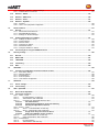


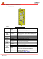

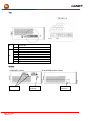

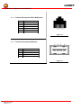


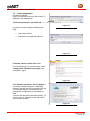
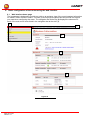

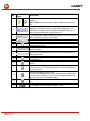
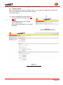

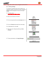


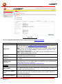
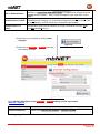
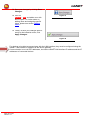


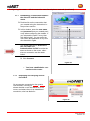
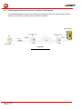
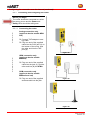

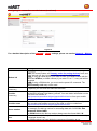
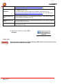


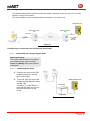

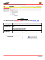

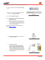

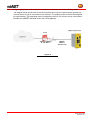
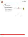

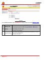

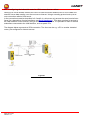

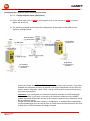

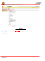


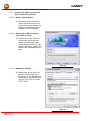
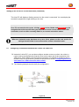


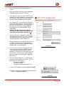
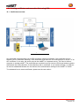


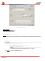
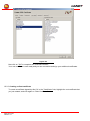

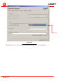
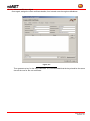


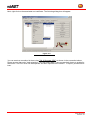
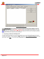
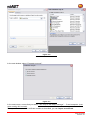

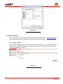
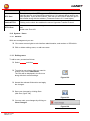


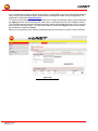
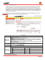


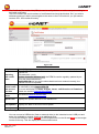
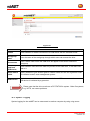
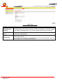


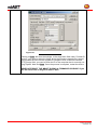

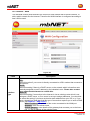


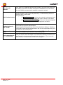

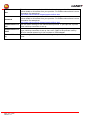
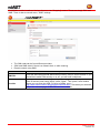
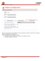

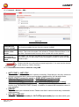
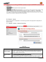
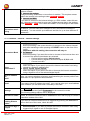
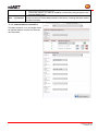
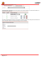
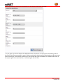
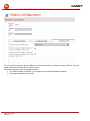

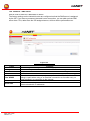


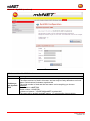
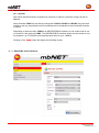


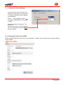
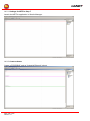


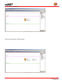

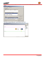
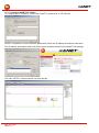

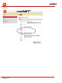


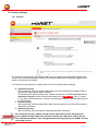
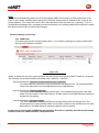
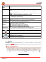

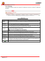


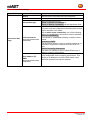
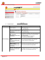
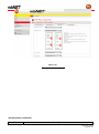


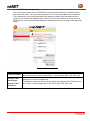


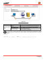
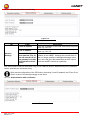


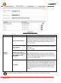
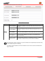

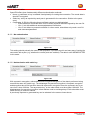

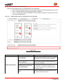
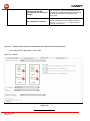
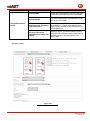
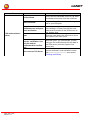
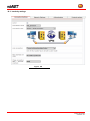


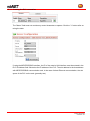
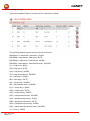
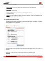
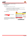
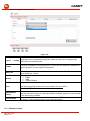

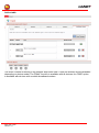

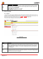

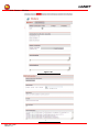
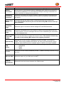
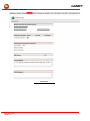
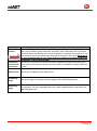
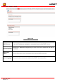
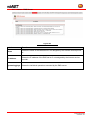
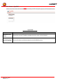
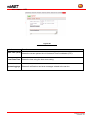
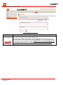

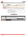
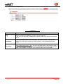
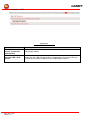
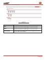


![[+7&ar] - GbbKolejka](http://vs1.manualzilla.com/store/data/006422040_1-b45bf1e30b46cf5ccf9cadeab2e21bc5-150x150.png)