1
r<
MONITOR HEATING SYSTEMS
Service Manual
MONITOR 21
MONITOR 40
The information contained herein is proprietary to Monitor Products, Inc. shall not be disclosed, duplicated, nor
otherwise copied in whole or part for any other purpose without express written permission of the Legal
Department of Monitor Products, Inc. This data is issued to authorized Monitor Servicing Personnel for guidance
in the installation and maintenance of the subject product and is intended for use by authorized Monitor service
personnel only. Further, Monitor Products, Inc. reserves the right to make improvements and corrections and to
alter apecifications of products described herein, at any time without prior notice.
P.O.BOX3408
PRINCETON, NEW JERSEY 08543
MONITOR HEATING SYSTEMS
Table of Contents
Section 1: Description
Page 1-7
1-1 Introduction; 1-2 Physical Specifications; 1-3 Functional Description; 1-4 Description; 1-5 Spill Tray; 1-6 Heater Cabinet; 1-7 Combustion System; 1-8 Combustion Chamber; 1-9 Burner Pot; 1-10 Combustion Ring Assembly; 1-11 Burner Cap; 1-12 Flame Sensor; 1-13 Igniter;
1-14 Combustion Air System; 1-15 Flue Pipe; 1-16 Combustion Blower;
1-17 Heat Exchanger; 1-18 Air Circulation Fan; 1-19 Air Pressure
Switch; 1-20 Fuel Delivery System; 1-21 External Fuel Tank; 1-22
Fusible Link Valve; 1-23 Fuel Constant Level Valve; 1-24 Solenoid
Pump; 1-25 Electrical System; 1-26 Microprocessor; 1-27 Temperature Sensor; 1-28 Safety Mechanism; 1-29 Cloth Covered Exhaust
Pipe; 1-30 Air Circulation Fan Guard; 1-31 Fuse; 1-32 Overheat
Protector Switches
Section 2: Installation
Page 9—20
2-1 Introduction; 2-2 Physical Placement of Heater; 2-3 Drilling
Requirements; 2-4 Power Requirements; 2-5 Fuel Tank Requirements; 2-6 Temperature Sensor Wiring Requirements; 2-7 Building
Codes; 2-8 Un-packing; 2-9 Installation of Flue Pipe Window Kit;
2-10 Installing an Extension Kit; 2-11 Typical Monitor Lifter Pump
Installations; 2-12 Uses for the Elbow Adapter Kit; 2-13 Fuel Tank
Installation; 2-14 Heater Installtion
Section 3: Operation
Page 21—30
3-1 Introduction; 3-2 Operating Specifications; 3-3 Operating Controls and Indicators; 3-4 Pre-operation Check List; 3-5 Operation; 3-6
Manual Heater Operation; 3-7 Automatic Heater Operation; 3-8
Reprogramming the Monitor Heater; 3-9 Heat Sensor; 3-10 Monitor
Shutdown; 3-11 Out of Fuel; 3-12 Recovery from a Power Failure; 3-13
Recovery from Overheat Condition; 3-14 Recovery from Blown Fuse
Section 4: Maintenance
4-1 Introduction; 4-2 Periodic Maintenance; 4-3 Inspect Exhaust/Air
Lines; 4-4 Verify Igniter Operation; 4-5 Clean Fuel Constant Level
Valve Filter; 4-6 Cleaning Fusible Link Valve Intake Fitting on M-21;
4-7 Corrective Maintenance; 4-8 Replacement of Fuses; 4-9 Fuel
Contamination
Page 31 — 35
MONITOR HEATING SYSTEMS
Table of Contents
Section 5: Servicing
•
5-1 Introduction; 5-2 Measurerment of Fuel Flow rate; 5-3 Removal of
Water Deposits and Contaminants from Fuel Constant Level Valve
and Fuel Lines; 5-4 Cleaning the Burn Chamber; 5-5 Cleaning the
Fuel Inlet
Page 37—38
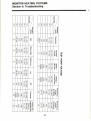
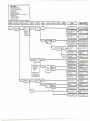
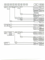
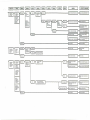
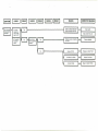
Section 6: Troubleshooting
Resistance Values
component Voltage Readings
Test Point Voltage
Troubleshooting Diagrams (Mecanical)
Troubleshooting Diagrams (Electrical)
Page 39—51
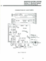
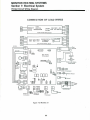
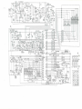
Section 7: Electrical System
Monitor 40 Printed Circuit Board Wiring Diagram
Monitor 21 Printed Circuit Board Wiring Diagram
Schematic
Page 52—54
MONITOR HEATING SYSTEMS
Section 1: Description
1-1 INTRODUCTION
The Monitor Heating System represents "state of
the art" technology and, although the heater is
sophisticated, it is simple to operate, takes little
time to maintain and requires minimum servicing.
The Monitor is a totally integrated heater consisting
of a housing(cabinet),a combustion system, an air
circulation system, a fuel delivery system and
micro-computer system.
Redundant safety devices are included in the
heater's design to protect the user from injury and
the heater from damage.
This section describes the heaters and their components.
Since a number of components have multiple functions, a component may be described more than
once.
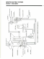
by visually examining a series of indicators on the
Control Panel.
A Temperature Selector Control permits the user to
set the temperature to the level desired in the room.
Upon commencing heater shutdown, a post-purge is
run.
All heating operations cease-except for the air
circulation fan and the combustion fan which continue. The post-purge continues for three minutes
after a flame goes out.At this point, heater operation
stops completely.
Auromatic operation of the Monitor 40 and Monitor
21 is controlled by a microprocessor with four sets of
Time/Temperature programming per day.
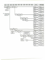
PRE-PURGE
PRE-HEAT
1-2 PHYSICAL SPECIFICATIONS
Listed below, are the physical specifications
apply to the Monitors:
that
Monitor 40:
Height:26.6" (67.5cm)
Width:28.7" (73cm)
Depth:13.8" (35cm)
Weight:82 Ibs (37kg)
Flue Pipe Hole:2'/2"(65mm)diameter
Monitor 21:
Height:25.6" (65cm)
Width:20.9" (53cm)
Depth:12.4" (31.5cm)
Weight:55 Ibs (25kg)Empty
Flue Pipe Hole:2Y2(65mm)diameter
IGNITION
COMBUSTION
HEATING
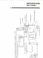
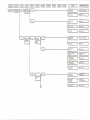
1-3 FUNCTIOMNAL DESCRIPTION
An overview of the functional operation of the
Monitors is diagrammed by Fiqure 1-1 and is described as follows:
Monitor operation always begins with a pre-purge
and a pre-heat, which must be completed before
SHUTDOWN
MONITOR HEATING SYSTEMS
Section 1: Description
mechanisms.
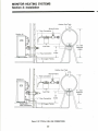
1-5 SPILL TRAY
The Spill Tray:
- Protects the floor from damage resulting from
fuel spillage.
- Provides a secure, tip-resistant heater base.
Metal retainers (2) secure the heater to the Spill
Tray.
The legs are positioned with in the circular indentations.
1-6 HEATER CABINET
A steel Cabinet holds and protects all internal
components.
A number of primary parts are assembled to form
this housing.
1-7 COMBUSTION SYSTEM
The Combustion System is responsible for the
production of heat which is circulated into the room.
1-9 BURNER POT
Designed specifically to support combustion, the
Burner Pot (refer to Figure 1-2) contains a series of
air holes, an igniter tube (to accommodate the
Igniter), and a fuel inlet fitting (interconnects the fuel
line). It is secured to a mounting plate near the
bottom of the Combustion Chamber.
The Combustion Ring Assembly is seated on three
(3) screws in the Burner Pot.
1-10 COMBUSTION RING ASSEMBLY
This assembly is a special structure, designed to
promote efficient combustion.
1-11 BURNER CAP
Secured by tabs and a screw on the Burner Pot, the
Burner Cap "shapes" the flame into its comfiguration
and height.
1-12 FIAME SENSOR
Mounted on the outside wall of Combustion Chamber, the Flame Sensor always supervises the flame.
In the Combustion Systems a mixture of fuel and air
is burned to produce heat. Air is drawn from outside
the dwelling to Combustion Chamber. At the same
time, fuel is metered from a storage tank into this
same Combustion Chamber. Within the chamber,
the air/fuel mixture is ignited to produce heat.
The Monitor combustion systems are safeguarded
by a pair of overheat protector switches; They will
shut down the heater (to protect it from damage) in
the event of excessive heat build-up. The overheat
protector switches reset automatically after cooling
down.
The Igniter is secured by a bracket and screw to the
igniter tube. The cover plate is secured to the
combustion chamber by three (3) phillips head
screws.
1-8 COMBUSTION CHAMBER
This tall cylinder is positioned on the Heater Base.
It is secured to the base by phillips head screws.
1-14 COMBUSTION AIR SYSTEM
The Combustion Air System channels air to and
from the heater.
Connected to the Combustion Chamber are the
igniter, (located within the chamber) a fuel line, the
Heat Exchanger, and a Flame Sensor.
Outside air is drawn into the heater by the Combustion Blower through an airway to the Combustion
Chamber.
Within the Combustion Chamber are the Burner Pot,
the Combustion Ring Assembly and the Burner Cap.
Access to those internally-located parts is facilitated by a removable Service panel. A window on the
panel lets the technician visually examine the combustion process(i.e. glowing igniter or proper flame
color).
A Combustion Blower draws the intake air into the
through a Flue Pipe. This air enters the Combustion
Chamber at the Burner Pot and mixes with the fuel
support combustion, Remaining air is heated and is
drawn into the Heat Exchanger.
1-13 IGNITER
Located within the igniter tube of the Burner Pot, the
Igniter is designed to pre-heat the Burner Pot and to
vaporize and ignite the air/fuel mixture to start the
combustion process.
An airway, in the Cabinet Base, extends from the
intake fan of the Combustion Blower to the hollow
base of the Combustion Chamber. This airway
channels air to the Combustion Chamber.
As the heated air passes through the Heat Exchanger, an Air Circulation Fan blows room air past the
Heat Exchanger and out again into the room, heating passing air by convection. Exhaust vapors exiting from the Hear Exchanger are vented through the
Flue Pipe.
The Flame Sensor is mounted with two (2) phillips
head screws onto the wall of the Combustion
Chamber.
A deterioration of air pressure at the Air Pressure
Switch is an abnormal condition; the heater is shut
down by the malfunction.
MONITOR HEATING SYSTEMS
Section 1: Description
Table 1-1 COMBUSTION AIR CONTROL
1-15 FLUE PIPE
Flue Pipes are available in three (3) sizes. This
provides the flexibility to meet the installation
requirements for dwelling of various wall thicknesses.
One side of the Flue Pipe contains a "T"-shaped
fitting consisting of four ports. This side is mounted
on the interior wall of the dwelling. The pipe side of
the Flue Pipe is vented outside the dwelling.
The Flue Pipe Assembly consists of two concentric
tubes. Outside air is drawn through the cylindrical
space between the tubes.
Combustion by-products are vented through the
inner tube.
As the cool air enters, it is heated by the hot air that
is exiting the system.
A large-bore, flexible hose connects the air inlet port
on the Flue Pipe with the Combustion Blower; a
cloth-covered metal pipe connects the Combustion
Blower with the exhaust outlet on the Flue Pipe.
IMPORTANT: If extension kits are utilized, use the
correct damper as follows:
Extension kit
Up to 3 elbows with
Extra Short Extensior kit
Length: W/2"-T/6"
Up to 3 elbows with
Short Extension Kit
Length: 1lV2"-20'/4"
Up to 3 elbows with
Medium Extension Kit
Length: 20'A"-38"
Up to 3 elbows with
Long Extension Kit
Length: 38"-73"
M-40
M-21
"S" damper
"S" damper
Burn Mode
Fan Speed
Solenoid Damper
High
High
Off (Open)
Medium-High
High
Off (Open)
Medium-Low
Low
On (Close)
Low
Low
On (Close)
1-17 HEAT EXCHANGER
An inlet at top of the Heat Exchanger permits the
heated air to travel from the Combustion Chamber
into the exchanger.
An outlet, at the bottom of the exchanger, permits
combustion by-products to be vented to the Flue
Pipe.
While moving through the Heat Exchanger, the hot
air within the exchanger heats the outside metal
walls. The hot metal walls, in turn, heat air that is
pushed past the exchanger and is circulated into
the room. An air baffle, directly in front of the
exchanger, deflects the heated air upwards, and out,
through the louver assembly.
A pair of Over-Heat Protector Switches protect the
heater from damage due to excessive heat built-up.
1-18 AIR CIRCULATION FAN
"S" damper
"E" damper
"E" damper
"S" damper
unused
unused
1-16 COMBUSTION BLOWER
The combustion blower on the Monitor 21 is a dual
function fan.
The intake fan draws in outside air thru the flue pipe
for internal combustion. The cooling fan which runs
on a common shaft with the intake fan circulates air
inside the heater cabinet to keep internal components cool.
The Monitor 40 combustion blower has a two stage
intake fan.
Burner modes control fan speeds and the solenoid'
damper in the blower casing. Those functions are as
follows:
Both Monitor circulation fans are driven by twospeed motors and are designed to circulate the
heated room air.
If the heater is running in low and medium-low burn
modes, the fan also runs at low-speed; in mediumhigh or high burn modes, the fan advances to
high-speed.
Operation of the fan is controlled by the microprocessor and fan thermostar switch (52°C/126T-on, 35°C/95°F---Off)
Physically assembled with a protective wire cage for
the Monitor 40 and metal mesh cage for Monitor 21,
the entire fan assembly is secured to a bracket on
the rear of the Heater Cabinet.
A metal conduit, at the rear of the heater, protects
the fan wiring from damage.
1-19 AIR PRESSURE SWITCH
This switch consists of a rubber diaphragm which
senses changes in air pressure(it is connected to
the Combustion Blower) and normally-open, micro
switch.
Should an abnormal pressure differential exist, the
switch opens to disable the circuitry that controls
MONITOR HEATING SYSTEMS
Section 1: Description
the supply of fuel. Since the flow of fuel to the Burner
Pot is cut off.the flame extinguishes (after all fuel
currently in the line has been consumed), and the
Burner Status Indicators blink.
This safety mechanism can be triggered by several
conditions:
- Leak or loose connection in air line
- Leak, loose, or broken tubing which connects
the Air Pressure Switch with the Combustion
Blower
- Clogged or blocked Air Line
- Blocked or clogged Flue Pipe
- Intake port of Combustion Blower is blocked.
- Combustion Blower is inoperable
1-20 FUEL DELIVERY SYSTEM
Fuel Delivery is a very important aspect of the
Monitor's operation.
The fuel flow must be maintained at a level corresponding to the burn mode, so that combustion can
be conducted efficiently.
Fuel moves by gravity-flow from the external fuel
storage tank or the capsule fuel tank to the Fuel
Constant Level Valve.
The Solenoid Pump meters the flow of fuel from the
Fuel Constant Level Valve to the Burner Pot.
The metered flow of fuel is carried to the Burner Pot
by a copper fuel line.
1-21 EXTERNAL FUEL TANK
The Monitor 21 gives the user the option of either
using the internal capsule tank or hooking up to an
external fuel tank.
Fuel for the Monitors can be stored in, and fed from
an external storage tank. The tank, which generally
is dealer installed, should contain a shutoff valve, a
fuel filter and a vent. Installation of the tank should
conform to local regulations and to the specifications and guidelines documented in this Service
Manual.
1-22 FUSIBLE LINK VALVE
Basically, the Fusible Link Valve is a safety mechanism that cuts-off fuel to the heater in the event of
an overheat condition at the valve.
The fusible link valve is mounted as a standard item
on the Monitor 21. Located outside the rear of the
Heater Cabinet, the Fusible Link Valve is a springloaded device that cuts off the supply of fuel to the
heater when the temperature level (at the valve)
exceeds a predefined maximum limit.
An inlet on the bottom of the valve allows fuel to
pass into the heater. The handle-which can also
manually be opened or closed-sits on a springloaded stem which contains a low-melting point
alloy.
The fusible link valve can be externally mounted on
the Monitor 40 if required.
1-23 FUEL CONSTANT LEVEL VALVE
This valve has an automatic shutoff safety mechanism and a Fuel Set Lever. The safety mechanism
prevents fuel from flooding or overflowing from the
fuel reservoir. The Fuel Set Lever resets the float so
the Fuel Constant Level Valve can resume operation.
The fuel reservoir is a tank which contains a float
assembly, a safety mechanism, and a priming lever.
Both the Monitor 21 and 40 fuel control valves are
basically the same, however they are of different
size and material and can not be interchanged.
Fuel enters the Fuel Constant Level Valve through
an inlet at the bottom of the reservoir. As the level
of fuel rises, it passes through a filter (which
removes most particles and foreign matter from the
fuel), flows up through an open inlet valve and
enters the tank.
IMPORTANT:
The Fuel Constant Level Valve filter
should be cleaned or replaced periodically. Time intervals will depend
on purity and quality of fuel.
Within the Valve, a float mechanism controls the
level of fuel that will be permitted to the reservoir. As
the fuel level drops, the float drops down to increase
the inlet valve opening to admit more fuel into the
valve. When the fuel level reaches its muximum
volume, the float rises to shut the inlet valve.
In the event that fuel within the reservoir rises to an
abnormally high level, a float within the reservoir
rises to trip a safety lever. This safety lever drops to
prevent fuel from entering into the reservoir.
Should a foreign substance cause the inlet valve to
stick (or prevent it from opening), the Fuel Set Lever
is utilized to free the valve and to admit fuel to the
reservoir.
CAUTION:
Care must be taken to prevent
dust, dirt, or other debris from
clogging or blocking the inlet
valve.
1-24 SOLENOID PUMP
The Solenoid Pump is mounted the Fuel Constant
Level Valve, controlled by a microprocessor, and
MONITOR HEATING SYSTEMS
Section 1: Description
During installation make sure that all Exhaust Lines
are tight. Do not operate the heater without the
insulating covers.
four modes (High, Medium-High, Medium-Low, Low)
fuel flow is delivered to the Burner Pot.
1-25 ELECTRICAL SYSTEM
1-30 AIR CIRCULATION FAN GUARD
Electrical power is supplied to the Monitor to run the
Microprocessor and the other electrically-energized
component.
This guard is an integral part of the fan assembly.
The guard protects the user against physical injury
which could occur from accidental contact with
revolving metal fan blade.
Electrically operation of the Monitor can be thought
of as having the following eight (8) distinct phases:
plug in; turn-on; pre-purge/pre-heat; ignition; precombustion; heating; Shutdown and post-purge.
1-31 FUSE
2-amp. and 10-amp., 125VAC, fuses protect the
heater from damage resulting from power overloads.
All electronic diagrams, Such as wiring diagram,
circuit board layout, and electrical schematic can be
found in Section 7 of this Service Manual.
1-26
In the event of a power surge or internal wiring
hazards, the fuse opens and power to the heater is
cut off.
MICROPROCESSOR
Principally consisting of a 64-pin Integrated Circuit,
the Microprocessor provides safety timings, controls
relays and provides clock and thermostat functions
for the Monitor heater. A component layout of the
Printed Circuit Board is found in Section 7 of this
Service Manual.
The electrical outlet into which the heater is connected should be protected by at least a 15-amp.
fuse or circuit breaker.
1-32 OVERHEAT PROTECTOR SWITCHES
Connected in series, two (2) normally-closed Overheat Protector Switches safeguard the heaters
against damage due to overheating.
1-27 TEMPERATURE SENSOR
The sensor which is capable of sensing room temperature within a range of 42T to 96°F, can be left
mounted on the back of the heater cabinet or be
wall mounted.
The Monitor 21 switches are rated 110°C (230°F).
The Monitor 40 switches are rated 115°C (239°F).
Should a Monitor overheat (internal temperatures
rise beyond 110"c (230°F) on the Monitor 21, 115°C
(239T) on the Monitor 40) either or both switches
will open to shut down the heater. After extinguishing the flame, the Burner Status indicators continue
to blink. The Overheat Protector Switches will automatically reser after cooling dowm.
Approximately 6Vz' (about 200 cm) of No. 20 AWG
Wire is supplied with the sensor to facilitate wall
mounting the sensor in a favorable location.
1-28 SAFETY MECHANISMS
Several safety mechanisms have been built into the
Monitor Heating System. These devices protect the
user against personal injury, protect the heater
against damage, and shutdown the heater if a
malfunction occurs.
Once the heater has cooled to 80°C (176°F), the
system can be restarted. To restart the Monitor,
proceed as follows:
A.
B.
C.
D.
E.
1-29 CLOTH COVERED EXHAUST PIPE
Insulating cloth covers are to be placed over all
metal surfaces of the Exhaust Line during installation.
Since combustion by-products are vented at elevated temperatures, the Exhaust Pipe will become
hot during operation. The insulating cloth covers
protect the user from burn hazards associated with
accidental contact with these heated metal surfaces.
5
Press ON/OFF Switch to OFF.
Allow heater to cool.
Troubleshoot the cause of the overheat.
Press ON/OFF switch to ON
Proceed with normal operation.
MONITOR HEATING SYSTEMS
Section 1: Description
H
QC
CD
6
MONITOR HEATING SYSTEMS
Section 1: Description
CO
m
co
O
Tl
O
co
CO
en
CO
O
33
MONITOR HEATING SYSTEMS
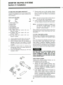
Section 2: Installation
RECOMMENDED TOOL KIT FOR MONITOR
HEATER SERVICE TECHNICIANS
1) #2 Phillips Head Screwdriver
2) Steel Tape Measure
3) Felt Tip Pen or Pencil
4) Caulking Material (exterior grade)
5) Electrical Drill
(reverse capability recommended)
6) Hole Saw, Saber (Jig) Saw, or other appropriate
tool for cutting a 2.5" diameter hole for flue pipe
7) Rubber Clipping Tool
8) Long Drill Bit—1/2"
9) #2 Standard Screwdriver
10) Adjustable Wrenches (various sizes)
11) Copper Tubing Cutter
12) Copper Tubing Flaring Tool
13) V.O.M.(Volt, OHM. Meter with shielded probes)
14) Level
15) Plumber's Pipe Thread Tape
16) Small assortment of Self-Tappeng Screws
17) Assorted Pliers (Slip Joint, Needlenose, Cutting,
Lock Joint)
18) Phenolic Probe or Insulated Screwdriver
19) Supply of 125V, 3 Amp fuses
20) Floor mat to cover carpeting
21) Quart size pan for draining fuel
2-1 INTRODUCTION
Installing the Monitor System at the user's location
can be performed quickly and economically. The
Monitor 21 can be used as either an internally fueled
(capsule tank) or remotely fueled System. The
Moni-tor 40 model is strictly a remotely fueled
system and borh are externally vented. As such both
need the installation of an externally vented intake/
exhaust system and if remotely fueled, will need the
installation of a remote fuel storage tank.
By completing each step of the easy-to-follow
installation instructions (each step should be completed in the exact order specified), the Technician
is directed through the installation process.
This section contains all relevant installation information including:
- Installation specifications
- List of installation tools
- Alternative types of venting systems (and installation procedures for each)
- Basic requirements for fuel tank installation
- Instructions to install the Monitor System
IMPORTANT:
Before beginning installation of the
Monitor vented heating system (including any electrical wiring and
fuel supply equipment), check local
building.electrical, mechanical and
fire codes. The requirements of
these codes must be followed to
Insure lawful installation and use.
2-4 POWER REQUIREMENTS
WARNING
THE MONITOR POWER CORD MUST BE PLUGGED
INTO A DIRECTLY ACCESSIBLE WALL OUTLET.
DO NOT USE AN EXTENSION CORD TO MAKE
THIS ELECTRICAL CONNECTION.
The heater can be located almost anywhere within
the dwelling provided that electrical, fuel, and exhaust specifications are met.
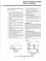
2-2 PHYSICAL PLACEMENT OF HEATER
In addition to the space taken up by the heater,
interior space must also be reserved for free air
circulation. Remove all combustibles from the heating area.
Line current to the system should be 120 VAC at 60
Hz. The electrical system should be protected
against current overload by means of at least a
15-ampere fuse or circuit breaker.
Unless building or fire codes dictate otherwise, the
Monitor system can be placed on any floor surface
(including carpeting or other combustible material)
and provide safe operation.
NOTE:
2-3 DRILLING REQUIREMENTS
Through-the-wall Flue Pipe installation requires that
a 2 'A" (65mm) hole be drilled through the dwelling
wall (interior to exterior). The hole must be pitched
downward toward the outside at an approximate
angle of 2°(about '/ 2 " per foot). The appropriate wall
area (in which hole will be drilled) must contain no
internal obstacles such as piping, wiring, air ducts,
or studs.
The wall outlet should supply electricity for
the Monitor system only. Do not connect
any other electrical appliance to it.
CAUTION:
9
In some installations, it may be
best to hard-wire the heater to the
house circuits. A competent,
licensed electrician should do
this.
MONITOR HEATING SYSTEMS
Section 2: Installation
NOTE:
2-5 FUEL TANK REQUIREMENTS
WARNING:
INSTALLATION OF ANY REMOTELY LOCATED
FUEL TANKS MUST COMPLY WITH ALL LOCAL
STANDARDS AND/OR BUILDING CODES.
D.
Remove the spill tray from shipping carton, and
remove the plastic bag.
E. Remove the plastic bag covering the hearer.
F. Remove the plastic bag containing the heater
parts.and set it aside.
G. Remove the Flue Pipe from the rear of the
heater. When ready to install, separate Flue
Pipe from cardboard packing materials.
H. Firmly grasp cabiet handles (one on each side
of heater cabinet) and lift heater off the cardboard shipping base.
I.
Check for parts as listed in Monitor Owners
Guide.
Heater fuel (crystal clear kerosene only) can be
stored in remotely located storage tanks ranging
from 55 gallon drums to 275 gallon tanks. When
using large tanks a pressure regulator with a max. of
2.5 PSI should be installed near heater inlet.
CAUTION:
In some installations, it may be
better to install permanent fuel
tank plumbing. A licensed
Plumber should do this.
IMPORTANT: Only the standard-size Flue Pipe is
shipped with the heater. The Monitor dealer will also stock Medium
Flue Pipes, Window Kits, Extension
Kits, and other accessories that
may be required for non-standard
installations.
2-6 TEMPERATURE SENSOR WIRING REQUIREMENTS
A wall-mounted temperature Sensor gauges room
temperature and automatically regulates the heating
cycles of the Monitor System.
The standard sensor wire is 6 3 / 4 ' long and can be
left mounted on the back of the cabinet as shipped.
If this is not practical the sensor can be mounted on
a wall.
CAUTION:
The Dealer should complete the Registration Card at time of customer purchase and
return it to Monitor Products, Inc. as soon
as possible.
If sensor is to be mounted remotely be careful not to place it in
direct sunlight, on uninsulated
exterior walls in drafty areas etc.,
as this-will create an inaccurate
temperature reading.
2-7 BUILDING CODES
Fire regulations, electrical and other local building
codes may govern the installation and use of a
vented heater and related fueling systems. Prior to
installation, check and comply with all codes.
2-8 UNPACKING
Save all shipping materials until the Monitor has
been completely installed and is working properly.
A. Cut the two plastic ribbons that hold the shipping carton together.
B. Remove the top.
C. Remove from the shipping carton the Cardboard
(drilling) Template and the Owner's Guide.
10
MONITOR HEATING SYSTEMS
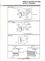
Section 2: Installation
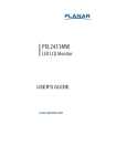
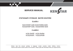
Frontal Clearance
i""1"11111
Combustible "iiniiiniiliii
Wall Any construction
above Flue Pipe
must not come
5 1 / » within 24" (60cm)"
(14cm) °f fr°nt obstacle
24"(60cm) or more or more
24"(60cm)
or more
5'/ 2 "
Body '
Clamp
8" (20cm)
or more
_J
Ground or slab surface
Heater
Overhead Clearance
Combustible
_.
i'l_l
I Front Obstacle
Flue Pipe
Non-combustible
-^.UIIIIIIIHIIIIIilllUIIIHIIIUllllUll
i
-Wall
24"(60cm)
or more
6V."
Body
Clamp
Heater—
Ground or slab surface
Side Clearance
Side obstacle
Body Clamp
18° (45cm)
or more
Heater
Flue Pipe
•Wall
60cm, 24in
13.5cm, 6in
13.5cm, 6in
15cm, 6in
15cm, 6in
25cm, 10in
100cm, 39in
100cm, 39in
Figure 2-1 FLUE PIPE CLEARANCES
11
MONITOR HEATING SYSTEMS
Section 2: Installation
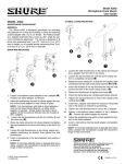
HOW TO PREVENT FREEZING IN COLD CLIMATE.
Exhoust Elbow
24" (60cm)
or more
L
Front Obstacle
20" (50cm) or more
SNOW SURFACE or GROUND
^
Long
Extension \
kit
:
=^
^
ff*- ^—r
Must be higher.
.'•'• •' '-i;:''^'-':'-:
0
Figure 2-2 FLUE PIPE CLEARANCES
12
: '.••• -.'••
Snow
MONITOR HEATING SYSTEMS
Section 2: Installation
NOTE:
After using the installation template as a
guide for drilling the flue pipe hole, the
Monitor Flue Pipe can be normally installed
according to the Illustration procedure in
the Monitor Manual.
Just in case the template was misplaced, the approximate flue pipe hole location measurements are
as follows:
Tha center of The Joint Pipe
opening, which connects
to the Flue Pipe.
M40
The Window Kit is available in two sizes. The Short
Window Kit accommodates windows from 20 to 32"
wide; the Long Window Kit accommodates windows
from 31 to 50" wide.
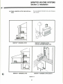
NOTE: The procedure below describes how a
Window Kit is installed in a double-hung
window. The Window Kit can also be installed in a vertical, sliding tylpe window.
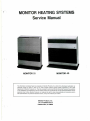
Install the Window Kit in the manner outlined below:
Back of Heater
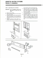
STEP 1: Install Flue Pipe in Window Kit
A. Push the rubber seal into the Flue Pipe hole on
the window kit frame. The hole on the seal
should be positioned at the exterior side of the
frame.
B. Using the four (4) Phillips head screws, fasten
the spacer to the frame.
C. With the arrow on the Flue Pipe pointing UP,
align the screw holes on the Flue Pipe with
those on the Spacer. Secure with three (3)
phillips head screws.
Fuel Inlet
The center of The Joint Pipe
2-9 INSTALLATION OF FLUE PIPE WINDOW KIT
A window kit makes it possible to vent the heater
from dwellings in which through-the-wall venting is
neither practical nor possible.
Back of Heater
M21
Fuel Inlet
Figure Figure 2-3
13
MONITOR HEATING SYSTEMS
Section 2: Installation
STEP 2: Install Window Kit in the Window
point where the inner and outer frame meet.
Expand the frame to fit the window tightly.
Adjust the position of the L-Adapter, if necessary. Tighten the set screw to secure the frame.
Secure the L-Adapter to the window sill with
two (2) wood screws.
F. Lower the window firmly down upon the top of
the Window Kit frame.
G. Measure the width of the upper (outer) window
(which is located in the outer track). Cut a
length of the Rubber Packing to this size.
Remove the protective backing and firmly
mount it onto the underside of the outer window.
E.
IMPORTANT: Prior to installation, clean the window frame of all dust, dirt, and
debris.
A.
B.
Raise the lower window
Place the window kit frame into the innermost
track of the window.
C. Expand the frame until it fits loosely within the
width of the window; it may be necessary to
loosen the large set screw on the frame in order
to do so.
D. Slightly lift window kit frame. Slide the LAdapter under the frame and position it at the
MONITOR HEATING SYSTEMS
Section 2: Installation
STEP 3: Install Window Lock
A special window lock replaces the usual clamshell lock.
To install the window lock, proceed as follows:
A. Turn locking lever to left and disengage lock
from lock bracket.
B. Attach lock bracket to left-hand side of upper
window frame. Use the two wood screws
provided.
NOTE:
D.
If the lock bracket prevents the lower
window from sliding upward, notch the
bracket into the upper window frame.
Two adjustable-position stops are supplied to
accommodate various window sash thicknesses. If short stop is too small, remove two
retaining screws and brackets which hold the
short stop to the underside of the lock. Remove
the short stop and substitute the long stop.
Adjust to proper position, and secure with
screws and washers previously removed.
(Before securing the stop to the window,
remove the protective backing and firmly stick
the stop packing onto the underside of the
stop.)
NOTE:
C.
Slip lock into lock bracket.
IMPORTANT: Window can be locked by turning
locking lever to right; to open, turn
locking lever to left and remove
lock from bracket.
Windows with deep sills may require the
use of an extra intake and exhaust elbow
to provide clearance for flue pipe hook up.
A piece of the air intake line can be cut to
join the two intake elbows together.
Deep Window Sill
One Exhaust Elbow
Two Intake Elbows
Figure 2-5
15
MONITOR HEATING SYSTEMS
Section 2: Installation
IMPORTANT: The PVC air line is longer than the
exhaust line and may need to be cut
to size. Be sure, however, to thoroughly deburr all rough edges.
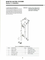
2-11 INSTALLING AN EXTENSION KIT
Installing an Extension Kit requires the construction
of an air line and the exhaust line. The air line is
connected between the Air Supply Elbow at the rear
of the heater and the air inlet port on the Fiue Pipe.
Similarly, the exhaust line is connected between the
joint pipe at the rear of the heater, and the exhaust
port on the Flue Pipe.
Figure 2-6 COMPONENTS OF EXTENSION KIT
ITEM#
DESCRIPTION
ITEM#
DESCRIPTION
1
PIPE, Air supply
6
PIPE CLAMP, Bottom
2
JOINT, Air line
7
SCREW, Legs, mounting
3
ELBOW 90° Air line
8
SCREW, Pipe Clamp
4
LEG, Wall-standoff
9
BOND, Adhesive
5
PIPE CLAMP, Top
16
MONITOR HEATING SYSTEMS
Section 2: Installation
For more detailed information look under Kerosene
Lifter manual.
2-13 TYPICAL MONITOR LIFTER PUMP INSTALLATIONS
MONITOR™ KEROSENE LIFTER
c
MONITOR™ KEROSENE LIFTER
(CAN BE POSITIONED BEHIND UNIT)
MONITOR™ KEROSENE LIFTER
MONITOR™ KEROSENE LIFTER/GRAVITY
Figures 2-7
17
MONITOR HEATING SYSTEMS
Section 2: Installation
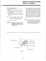
F.
2-14 USES FOR THE ELBOW ADAPTER KIT
Convert trom Monitor 20/30 to 21/40 using an elbow
adapter Kit (part#8213) and utilizing existing flue
pipe installation.
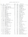
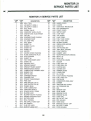
PARTS LIST EXPLODED
Name
Remove metal cap on side mounted exhaust
port of flue pipe and replace into the port (the
Monitor 21/40 is now ready to be positioned
into place.)
NOTE:
Be sure the exhaust elbow is firmly fixed on
the flue pipe with a joint supporter.
G. Insert air suppoy elbow opening over flue pipe
air intake flange and secure with hose clamp.
No
Ref.
of
in
No.
Part
Unit
1 Exhaust Pipe Clamp
2 Exhaust Elbow
1
3 Exhaust Joint
1
4 Joint Supporter
1
5 Heat Insulation Cover
1
6 Self-Tapping Screws
2
7 Hose Clamp (this part comes with your
Monitor™ Heater)
8 Air Damper (this part comes with your
Monitor™ Heater)
9 Flue Pipe (this part comes with your
Monitor™ Heater)
NOTE: The Standard Air Damper is installed over
the flue pipe "air intaka flange." (To locate
flue pipe "air intaka flange", see your
Monitor™ Owner's Guide.)
Elbow adapter kits may also be used to raise a flue
pipe hige enough to clear certain base board heating systems.
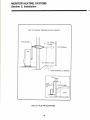
2-15 FUEL TANK INSTALLATION
Pictorial views of alternative types of storage facilities and delivery systems are illustrated (Figure
2-10).
A. Remove Monitor 20/30 heater and flue pipe.
B. Install Monitor 21/40 flue pipe into sleeve.
C. Slide the exhaust elbow onto the exhaust port
opening on the rear of the heater. (To locate
exhaust port opening, see your Monitor Owner'
s Guide.)
D. Secure the exhaust elbow by attaching the
exhaust pipe clamp to the heater cabinet with
two self-tapping screws.
E. Cover the adjustable exhaust pipe with heat
insulation cover.
Since fuel storage tank installation techniques vary
from place-to-place (often dependent upon applicable codes), a particular installation procedure
cannot be specifed. However, certain criteria govern
the fuel hook-up of the Monitor. Use the following
check list as a guide to the fuel storage facilities:
WARNING:
USE ONLY CRYSTAL CLEAR KEROSENE. NEVER
USE GASOLINE, WHITE GAS, CAMP FUEL OR
OTHER FLAMMABLE LIQUIDS. USE OF SUCH
FUELS CAN RESULT IN AN EXPLOSIVE FIRE AND
CAUSE SEVERE INJURY.
Fueling Options Available
Fueling of the Monitor Heating Systems can be
accomplished in one of 3 ways:
1. Capsule Tank (on the Monitor 21).
2. Gravity Fed Large Capacity External Tank:
Practical for large heating needs where bulk
delivery of kerosene is available. This system
should be installed by a qualified plumber or
fuel supply technician.
*3. Large Capacity External Tank with Pump: For
large heating needs where a gravity fed
system is not practical. An electric pump, the
Monitor™ Kerosene Lifter, especially designed
for use with Monitor heating systems.
*if a pumping system is used is used to supply fuel,
the inlit pressure to the heater must not exceed 2.5
psi.
Figure 2-8
18
MONITOR HEATING SYSTEMS
Section 2: Installation
55, 100, and 250 gallon tanks must contain:
To install a large capacity, gravity fed external tank,
follow the instructions below. Use of a qualified
installer is recommended.
•
•
•
•
•
•
•
•
Shut-off valve at tank outlet
Disposable fuel filter (protects heater against
condensation and other impurities)
Fueling inlet (protected by weather-proof cap)
Ventilation outlet
Clearance of at least 6' from any source of heat
Installation height of the bottom of the fuel tank
should be 16 inches or more above the floor
surface on which the heater stands. This
insures that inlet fuel pressure will be sufficient.
The top of the fuel tank should be no higher
than 8'/2 feet above the floor under the heater.
This insures that inlet fuel pressure will not be
excessive.
The horizontal length of piping should not
exceed 100 feet and should be free of sharp
bends or obstructions.
Allowable Height Dimensions:
• Bottom of tank-at least 16" above floor holding
heatere (maintains sufficient pressure)
• Top of tank-maximum of 8'/Y above floor
holding heater (prevents excessive line pressure)
• Position of Lifter-more than 8' above fuel inlet
of heater requires pressure reduction valve.
Piping should include no inverse U-type bends
(to avoid air locks, which could block the fuel
supply).
Only Va-inch OD copper tubing should be used.
The tubing should be bent carefully to avoid
crimping.
A fuel filter is recommended for use on the fuel
line near tank, and a shut-off valve should be
installed at the tank.
Flare connections should be used at the fusible
link valve connection on the heater and at the
fuel filter to be installed at the tank.
The fuel tank should be located no closer than
6 feet to a source of heat.
The fuel tank should have an opening for filling
on the top and a vent with a weather-proof cap
on the side. One some tanks the vent and fill
spout use the same opening.
RECOMMENDATION
Pipe fittings in the fuel supply to the Monitor heating
systems should be sealed with pipe thread tape.
The supply line from the tank to the Monitor™
Kerosene Lifter must be absolutely air tight. 275
gallons and bigger tanks should have a 2.5 P.S.I.
max pressure reducer to avoid excessive pressure
at heater inlet.
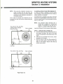
2-16 HEATER INSTALLATION
The Monitor heaters can be physically situated on
carpeting or other combustible flooring with complete safety. The selected heater site must be
accessible to an electrical outlet, must support free
air ciculation (both internal and external), and must
not contain combustible materials in the heater's
immediate vicinity.
Pressure
Reducer
Lifter
Interior or
exterior gravityfed 55, 100, or 275gallon tank
Lifter circulates
fuel from remote
storage tank
Figure 2-9 ALTERNATIVE SOURCES OF FUEL STORAGE
19
MONITOR HEATING SYSTEMS
Section 2: Installation
Outdoor Fuel Tank
Shut-off Valve
Y8" Flare Connection
Monitor 40
8'/ 2 feet
maximum
(2.6m)
Y8" Flare Connection
(0.4m)
Ys" OD Copper Tubing
I
Outdoor Fuel Tank
Shut-off Valve
Y S " Flare Connection
r
II
'
Fuel Filter
s" Flare Connection
Fusible Link
Valve Connection
T
16"
(0.4m)
s" OD Copper Tubing
J
Figure 2-10 TYPICAL FUEL LINE CONNECTIONS
20
8'/2 feet
maximum
(2.6m)
MONITOR HEATING SYSTEMS
Section 3: Operation
- Circulation Fan Output : 388 cubic feet/min.
- Fuel source : Remote, separate tank
- Potential heating area : 900-3200 sq. feet
3-1 INTRODUCTION
Monitor is an easy-to-operate vented kerosene
heater. Routine operation features high BTU output,
automatic adjustment of room temperature, low fuel
and power consumption, and choice of automatic or
manual heater operation.
The energy form the combustion process is
released in the from of heat and vaporized water.
Normally, heating systems discharge water from
combustion to the atmosphere without condensing
it. This 93% efficiency rating means that, assuming
the water cannot be condensed, 93% of the heat
produced by the combustion process is recovered.
Assuming the water can be condensed, the efficiency is 87%.
This section provides all information necessary to
operate the Monitor Heating System. All operation
procedures specified should be performed in the
order in which they are described.
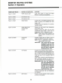
3-2 OPERATING SPECIFICATIONS
The following specifications apply to the operation
of the Monitor 40 and the Monitor 21:
NOTE:
Monitor 40
- Rated Efficiency (as applied to kerosene
heaters): 93%*
- Rated Efficiency (as applied to central heating
systems): 87%
— Power Consumption : as follows
HIGH
IGNITION BURN
340watts 65watts
MEDIUM-HIGH
BURN
62watts
Actual effective heating area depends upon
numerous factors such as type and severity
of climate, type of dwelling construction,
condition of dwelling, and thickness and
effectiveness of dwelling insulation.
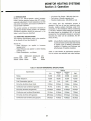
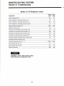
Table 3-1 lists Monitor 40 performance specifications at various user-selected heat output settings.
MEDIUM-LOW LOW
BURN
BURN
58watts
58watts
Table 3-1 HEATER PERFORMANCE SPECIFICATIONS
Setting
Specification
Low
Medium
Low
Medium
High
High
Rating
16,200
21,000
33,900
43,000
Heater Output/hr.
15,000
19,500
31,500
40,000
0.12
0.16
0.25
0.319
8-hrs/day burntime (5-gal. tank)
5.2days
3.9days
2.5days
2.0days
Continuous-use burntime (5-gal.tank)
41.7hrs.
31.3hrs.
20hrs.
15.7hrs.
8-hrs/day burntime (55-gal.tank)
57.3days
43days
27.5days
21.6days
Continuous-use burntime (55-gal.tank)
19.1 days
14.3days
9.2days
7.2days
286.5days
214.8days
137.5days
107.8days
95.5days
71.6days
45.8days
35.9days
Fuel Consumption (gal/hr)
8-hrs/day burntime (275-gal.tank)
Continuous-use burntime (275-gal.tank)
21
MONITOR HEATING SYSTEMS
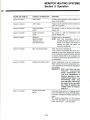
Section 3: Operation
- Circulation Fan Output : 176 cubic feet/min
- Fuel source : 1.32 U.S. gal., separate tank
optional
- Potentional heating area : 600-2000 sq. feet
Monitor 21
- Rated Efficiency (as apply to kerosene heater):
93%*
- Rated Efficiency (as apply to central heating
systems): 87%
- Power Consumption : as follows
HIGH
IGNITION BURN
250watts 52watts
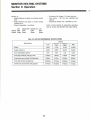
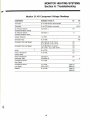
Table 3-2 lists Monitor 21 performance specifications at various user-selected heat output setting.
MEDIUM-HIGH MEDIUM-LOW LOW
BURN
BURN
BURN
51watts
SOwatts
SOwatts
Table 3-2 HEATER PERFORMANCE SPECIFICATIONS
Setting
Specification
Low
Medium
Low
Medium
High
High
Rating
9,600
11,700
17,400
22,000
Heater Output/hr.
8,900
10,900
16,200
20,400
0.07
0.09
0.13
0.164
8-hrs/day burntime (1.32-gal. tank)
2.4days
1.8days
1.3days
LOdays
Continuous-use burntime (1.32-gal.tank)
18.9hrs.
14.7hrs.
10.2hrs.
8.0hrs.
8-hrs/day brntime (55-gal.tank)
98.2days
76.4days
52.9days
41 .9days
Continuous-use burntime (55-gal.tank)
32.7days
25.5days
17.6days
14.0days
Fuel Consumption (gal/hr)
22
MONITOR HEATING SYSTEMS
Section 3: Operation
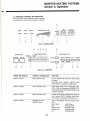
3-3 OPERATING CONTROLS AND INDICATORS
Several controls and indicators are used to operate
the heater and to monitor its performance as follows:
AUTO
RUN
EMPTY
BURNER STATUS
HIGH
LOW
4
6
Figure 3-1, INDICATORS
10
11 12
13
15
14
ON/OFF
TIMER SELECTOR
CLOCK
CLOCK I
AUTO
/TEMP SET 1st 2nd 3rd 4th
TIME/TEMP SET
OPERATION
I]
TIME
HOUR MINUTE SET
3 C3
UP /DOWN
TEMP
20
21
9
CLEAR
16
17
18
19
Figure 3-2, CONTROLS
FIGURE AND ITEM NO
CONTROL OR INDICATOR.
FUNCTION
Figure 3-1, Iteml
RUN Indicator Light
Light to indicate that power has been apllied
to heater.
Illuminates when operation ON/OFF pushbutton switch is pressed to position ON
Figure 3-1, Item2
AUTO Indicator Light
Lights when heater runs in automatic mode.
AUTO, RUN, and appropriate BURNER STATUS Indicators are illuminated simultaneously
if heater is burning.
Figure 3-1, ItemS
Empty Indicator Light
In case of using the cartridge tank, when the
fuel is empty, EMPTY Indicator Light blinks.
This Light is not provided with Monitor 40.
Figure 3-1, Item4
BURNER STATUS
Indicator Lights
Light in accordance
lows:
Heat Output
High
Medium High
Medium Low
Low
23
with heat output as folLight Pattern
8indicators-ON
6indicators-ON
4indicators-ON
2indicators-ON
MONITOR HEATING SYSTEMS
Section 3: Operation
FIGURE AND ITEM NO
CONTROL OR INDICATOR.
FUNCTION
Figure 3-1, ItemS
TEMP Indicator Light
Lights when heater is running and Digital
Window is showing the temperature.
Figure 3-1, Item6
AM Indicator Light
Figure 3-1, Item/
PM Indicator Light
Figure 3-1, ItemS
Digital Display
Indicates SET and ROOM temperature when
heater is running, and indicates time when
heater is Off.
Indicates time and temperature for automatic
operation setting.
Figure 3-2, Item9
TIMER SELECTOR
CLOCK/TEMP
position
Displays set and current room temperature
when heater is ON.
Displays current time (after time has been
programmed) when heater is OFF. Prior to
programming, 88:88 is displayed on clock.
NOTO: During routine heater operation, the
selector switch is normally set to this
position.
Figure 3-2, ItemlO
CLOCK SET
position
Programs current time on Clock by use of
HOUR and MINUTE push-button switches.
NOTO: Prior to programming current time,
Digital Display shows 88:88.
IMPORTANT: Once current time has been
programmed, press the SET
pushbutton switch with in 60
seconds.Otherwise clock display will revert to previously
programmed time, if any.
Figure 3-2, Item11
1ST Position
Programs first automatic heater operation.
When programmed, heater automatically operates at specified time and temperature (i.e. 6:
00 am., 70T), if set for AUTO, providing that
heater has been set for automatic mode of
operation.
TIME, TEMP, HOUR(UP), MINUTE(DOWN) and
SET push-button switches are used to program first operated time and temperature.
IMPORTANTO Once time and temperature
have been programmed, the
SET push-button switch must
be pressed with in 15seconds.
Otherwise, time and temperature will revert to previously
programmed time, if any.
When selector switch is set to this position, 1st
presently programmed time and temperature
are displayed.
Figure 3-2, Item12
2ND Position
Programs second automatic heater operation
as same as 1st position.
24
MONITOR HEATING SYSTEMS
Section 3: Operation
FIGURE AND ITEM NO
CONTROL OR INDICATOR.
FUNCTION
Figure 3-2, Item13
3RD Position
Programs third automatic heater operation as
same as 1st position.
Figure 3-2, Item14
4TH Position
Programs fourth automatic heater operation as
same as 1st position.
Figure 3-2, Item15
TIME push-button
switch
This switch is used to set time and change
display over.
Figure 3-2, Item16
TEMP push-button
switch
This switch is used set temperature and
change display over.
Figure 3-2, Item17
HOUR/UP,
MINUTE/DOWN
repetitive-action
push-button switch
Programs time or temperature.
NOTE: Each time push-button switch is
pressed, the digit advances in increments of one digit, If push-button is
pressed and held, the degits are
advanced repetitively.
Figure 3-2, Item18
SET push-button switch
"Sets" time and/or temperature.
If this control is not pressed after time and/or
temperature have been programmed, the time
and/or temperature programmed (as indicated
by display window) will not be accepted, and
will revert to previously programmed time and/
or temperature.
Figure 3-2, Item19
CLEAR push-button switch
Erases programmed time and temperature.
When cleared, time and/or temperature previously programmed and displayed disappear(s)
from window.
IMPORTANT: Both current time and automatically p r o g r a m m e d
time(s), temperature(s) will
have to be reprogrammed if
electrical operation is interrupted by power failure or by
disconnecting heater plug
from wall outlet. If this occurs,
the heater will go into MANUAL mode of operation and
maintain initial set temperature(72°F).
Figure 3-2, Item20
ON/OFF push-button
switch
ON position (push-button is "in")applies power
to the unit. When this occurs, the RUN indicator lights to indicate that heater operation has
begun.
OFF position (push-button is "out") remove
power from the heater. All circuits-except for
Clock and Air Flow — are shut down.
25
MONITOR HEATING SYSTEMS
Section 3: Operation
FIGURE AND ITEM NO
CONTROL OR INDICATOR.
FUNCTION
Figure 3-2, Item21
AUTO push-button
switch
Places heater in automatic mode of operation.
AUTO indicator lights to confirm automatic
operation.
Assuming that the heater has been properly
programmed, heater will operate automatically.
When pressed again, AUTO indicator goes out
and then heater will operate in MANUAL
mode. During manual operation, the user turns
heater ON and OFF, at will.
3-4 PRE-OPERATION CHECK LIST
3-5 OPERATION
After heater installation, but prior to Monitor heater
start-up, inspect the system for operational readiness. The following check list specifies those items
that should be inspected on a routine basis:
Operation of Monitor heater can be controlled
manually by the user, or run automatically by the
microprocessor.
x/
x/
x/
x/
x/
x/
x/
x/
x/
x/
x/
x/
x/
Paragraphs 3-6 through 3-10 provide the details of
heater start-up, operation, and shutdown. The
controls and indicators illustrated by Figure 3-1 and
3-2 are used to operate the system and to monitor
the heater's performance.
Check that the Monitor heater is plugged into
wall outlet
(120 Vac, 60 Hz)
Verify that adequate supply of kerosene is
available in fuel tank
Confirm that fuel is free of water or other
contaminants
Check fuel tank for good operating condition; it
must be free of rust, corrosion, and/or leaks
Inspect Fuel Line for signs of leaks, loose
connections, cracks, air pockets or blockages
Confirm that Fuel Valves on Fuel Tank and
Fusible Link Valve are open so fuel can flow
freely
Outside dwelling, check area immediately
around Flue Pipe for combustibles or obstructions to free air circulation
Inspect Air Line for cracks, loose connections
or blockage
Check Exhaust Line for cracks, loose connections or blockage
At rear of heater, verify that air flow to the Air
Circulation Fan is not blocked
Inspect dwelling interior and confirm that immediate area near heater is free of combustible
and objects that might interfere with free air
flow.
Make certain that Heat Sensor is not exposed
to drafts, direct sunlight, nor direct heat from
the Monitor.
Confirm that heater is level
3-6 MANUAL HEATER OPERATION
Operation of the heater is under the direct control of
the user (heater will not operate automatically). The
heater will, however, automatically respond to
changes in room temperature signaled by the Heat
Sensor to maintain the temperature of the room at a
comfortable level.
NOTE:
Resetting the Fuel Constant Level Valve is
necessary only if the heater is being started for the first time, hasn't been used for an
extended period of time, or if tank has run
empty. If priming is unnecessary skip to
step 2.
STEP1: Prime the Heater
Gently press and release the Fuel Constant Level
Valve Reset Lever four or five times.
STEP2: Select Manual Operation
If heater operation is in AUTO mode, press the
AUTO push-button switch and change Auto to
Manual mode.
STEPS: Select Temperature Setting
Press the TEMP push-button switch and press
either the UP or DOWN push-button switch to set
the digital set room temperature indicator to the
desired temperature, and then press the SET pushbutton switch.
If this inspection reveals any system deficiencies,
correct the problems before operating the heater.
26
MONITOR HEATING SYSTEMS
Section 3: Operation
IMPORTANT:
as appropriate.
In case no temperature is set, temperature will automatically be set at
72°F by microprocessor.
D.
Immediately after programming the 1st desired
time, press the SET push-button switch. This
step must be completed within fifteen seconds
after programming the time.
E. Press TEMP push-button switch.
F. Press UP and/or DOWN push-button switch(es)
to program 1st desired temperature.
G. Immediately after programming the 1st desired
temperature, Press the SET push-button switch.
This step must be completed within fifteen
seconds after programming the temperature.
STEP4: Turn Monitor On
Press the ON/OFF push button switch to position
ON. The RUN indicator light illuminates to indicate
that power has been applied to the instrument and
the heater is cycled for manual mode of operation.
3-7 AUTOMATIC HEATER OPERATION
Automatic operation is established by programming
the time/temperature settings for specific times. On
a daily basis, a maximum of four time/temperature
settings can be programmed.
STEPS: Program the Remaining Times
With the TIMER SELECTOR slide switch in the
appropriate positions, program the 2nd, 3rd, 4th
times as described above.
If, subsequently, it should be desired to switch to
manual mode of operation, the changeover can be
made at any time.
Be sure to press the SET push-button switch after
each time is programmed.
Proceed with automatic mode of operation in the
following manner:
IMPORTANT:
STEP1: Program Clock for Current Time
A. Position TIMER SELECTOR slide switch at
position CLOCK SET.
B. Press HOUR push-button switch to program
current hour on the Clock.
IMPORTANT:
NOTE:
STEP4: Select Automatic Operation
Press AUTO push-button switch. The AUTO indicator light will illuminate.
Be sure to clock for AM or PM, as
appropriate.
Both hour and minute digits on Display
Window are advanced in increments of one
by pressing the appropriate push-button
switch one time for each digit; digits can
also be advanced repetitively by pressing
and holding the appropriate push-button
switch.
Press MINUTE push-button switch to program
the current minute(s) on Clock.
D. Immediately after programming current time in
terms of hours and minutes, press the SET
push-button switch.
E. Place TIMER SELECTOR slide switch in position CLOCK/TEMP and verify that time displayed on Clock is the current time.
Should heater power be interrupted
by a power failure or by disconnection of the power cord, heater
reverts to MANUAL operation, and
all AUTO programming is erased.
STEPS: Turn Monitor ON
Press ON/OFF push-button switch to position ON.
The RUN indicator light will illuminate to indicate
that power has been applied to the heater.
From this point, heater operation is as follow example:
C.
6:OOAM
9:OOAM
1
76° F
5:OOPM
10:OOPM
80° F
68° F
64'F
Example
STEP2: Program the 1st Time/Temperature
A. Slide TIMER SELECTOR slide switch to position 1st.
B. Press TIME push-button switch.
C. Press HOUR and MINUTE push-button
switches to program 1st desired time.
IMPORTANT:
3-8 PEPROGRAMMING THE MONITOR HEATER
On occasion, it may be necessary to reprogram the
Monitor.
Reprogramming is performed as specified below:
Be sure to set the clock AM or PM,
27
MONITOR HEATING SYSTEMS
Section 3: Operation
3-11 OUT OF FUEL
During either manual or automatic operation of
heater, fuel in the tank may be depleted.
STEP1:
Reprogramming Current Time
(if necessary)
A. Set the TIMER SELECTOR slide switch to
position CLOCK SET.
B. Press HOUR and MINUTE push-button
switches to program new current time. Set
applicable time by watching Clock display.
C. Press SET push-button switch.
IMPORTANT:
The Monitor (in case of using external fuel tank) is
known to be out of fuel when all of the following
symptoms are present:
- Burner Status indicator lights blink.
- Absence of flame (visually verified through view
plate on wall of Combustion Chamber).
If SET push-button switch is not
pressed, current time will revert to
previously programmed time.
STEP1: Turn Heater OFF
Press ON/OFF switch.
STEP2: Reprogramming Automatic Operation
A. Set TIMER SELECTOR switch to appropriate
position (1st, 2nd, 3rd or 4th)
B. Press TIME push-button switch.
C. Press CLEAR push-button switch. Time displayed on window will disappear.
D. Using HOUR and MINUTE push-button
switches program new desired time by watching the Display Window.
E. Press SET push-button switch.
F. Press TEMP push-button switch.
G. Press CLEAR push-button switch. Set Temperature displayed on Window will disappear.
H. Using UP and DOWN push-button switches
program new desired temperature by watching
the Display Window.
I.
Press SET push-button switch.
STEP2: Fill Fuel Tank
A. Close shut-off valve at outlet of Fuel Tank.
B. Drain Fuel Tank (from bottom, if possible) to
remove all condensation, debris, and old fuel.
C. Fill Fuel Tank with fresh, crystal clear kerosene.
D. Upon completion of stepC, open shut-off valve
which was closed in stepA above.
STEPS: Turn Heater ON
Press ON/OFF switch to ON. Proceed with normal
heater operation.
The Monitor 21 (in case of using capsule fuel tank)
is known to be out of fuel as follows:
When the EMPTY indicator light illuminates
and flashes, a buzzer will sound for twenty
seconds. The burner mode is changed to "Low"
automatically, and then, the heater will shut off
after 30 minutes.
3-9 HEAT SENSOR
Heat Sensor is located on the rear of the cabinet. It
is recommended to leave the sensor in its original
mounted position. However should relocation be
necessary, choose a location for the sensor that is
not in the path of direct sunlight, drafts or the flow of
warm air from the heater. Loosen the screw and
release the sensor from the rear of the cabinet.
Fasten the sensor to the wall with the screw.
STEP1: Turn Heater OFF
Press ON/OFF switch and wait 15 minutes for the
heater to cool.
3-10 MONITOR SHUTDOWN
A simple one-step procedure is utilized to shutdown
the Monitor:
STEP2: Lift Out the Capsule Fuel Tank
Open the tank cover and lift out the capsule fuel
tank.
Press ON/OFF push-button switch to position OFF;
the RUN indicator will extinguish.
Turn the tank upside down, and remove the fuel
cap.
IMPORTANT:
STEP3: Fill the Capsule Fuel Tank
Fill the capsule fuel tank with fresh, crystal clear
kerosene by using a siphon.
The remaining burning time is indicated at the
Display Window.
Refueling:
Once heater has shut down, it cannot be restarted until post-purge cycle has been completed. If ON/OFF
switch is left in position ON, Monitor
operation will automatically restart
upon completion of post-purge.
STEP4: Reinstall the Capsule Fuel Tank
Replace and tighten the fuel cap. To insure proper
fuel flow, be sure the cap is secured correctly.
28
MONITOR HEATING SYSTEMS
Section 3: Operation
that impede free air circulation.
Install the tank with the arrow pointing forward, and
close the tank cover.
Look for debris and other obstructions at front of
heater, at Circulation Fan at rear of the heater, and
at Flue Pipe tip outside dwelling.
STEPS: Turn Heater ON
Press ON/OFF switch to ON. Proceed with normal
heater operation.
3-12 RECOVERY FROM A POWER FAILURE
The Monitor is equipped with an automatic reset
feature which restores (the manual mode of) operation following interruption of power to the heater.
Note, however, that a power-failure automatically
triggers a cooling and purge cycle; routine operation
will automatically be resumed following purge cycle.
STEPS:
Remove Louver Assembly
STEP6:
Clean Heater Interior
WARNING:
A switch to manual mode is automatic because the
absence of power to the microprocessor wipes-out
the programmed memory.
BEFORE PROCEEDING TO CLEAN HEATER, BE
SURE THAT HEATER INTERIOR IS COOL ENOUGH
TO TOUCH.
To recover from a power failure (automatic mode of
operation), proceed as listed below:
With a clean, lint-free, damp rag or other appropriate
cleaning material, wipe up all dust, dirt and debris
from exterior of cabinet, including exterior of Combustion Chamber and Heat Exchanger.
STEP1:
Program Current Time
STEP2:
Program Automatic Time/Temperature
operation cycles.
STEP7:
Replace Louver Assembly
STEPS:
Return to Automatic operation.
STEPS:
3-13 RECOVERY FROM OVERHEAT CONDITION
The Monitor is protected against damage resulting
from an overheat condition by two 110°C (Monitor
21), 115°C (Monitor 40) automatic reset thermostats.
STEP9:
Reconnect Monitor Heater Power Plug to
the Wall Outlet
Turn Heater ON
STEP10: Reprogram Heater Microprocessor
STEP11: Select Mode of Operation
In the event of an overheat the thermostats are
triggered to cut off the flow of kerosene to the
Burner Pot, the flame is extinguished automatically,
and user is alerted to the overheat condition by
blinking of the Burner Status indicators.
CAUTION:
To recover from an overheat condition, proceed as
outlined below:
STEP1:
Turn OFF Heater
STEP2:
Allow Monitor Heater to cool
NOTE:
Do not operate heater until problem has been diagnosed and cor
rected.
3-14 RECOVERY FROM BLOWN FUSE
All electrical components of the Monitor heater are
protected against power overloads and electrical
malfunctions by two 2-amp fuses and a 10-amp
fuse. Should fuse blow, the recovery procedure is
outlined below:
Be sure that heater is cool to touch.
A period of 30 to 45-minutes should be sufficient to
permit heater to cool completely.
STEP3: Unplug Heater
Disconnect heater power cord from wall outlet.
STEP4:
NOTE:
If after the completion of recovery
procedure, the heater overheats
again, something is wrong
Check for Cause of Overheating
Overheating is usually caused by objects
29
STEP1:
Turn Monitor OFF
STEP2:
Unplug heater
STEP3:
Remove louver assembly
STEP4:
Remove front cover
MONITOR HEATING SYSTEMS
Section 3: Operation
NOTE:
As the Front Cover of the Monitor 40 is
connected to the Printed Circuit Board by
Lead Wires, pull the Front Cover to the front
side slightly and remove the Connector of
the Lead Wires from the Printed Circuit
Board, and then, remove the Front Cover.
STEP7:
Reattach louver assembly
STEPS:
Plug heater power cord into wall outlet
STEP9:
Turn Monitor ON
STEP10: Reprogram heater
STEPS:
Locate and replace fuse(s)
STEP6:
Reattach front cover
(In case of the Monitor 40, be sure that
the connector is connected to the printed
circuit board.)
STEP11: Program Automatic operation cycles (if
applicable)
STEP12: Select Automatic operation (if applicable)
30
MONITOR HEATING SYSTEMS
Section 4: Maintenance
cally in order to sustain the efficiency of the Monitor
Heating Systems.
4-1 INTRODUCTION
Heater maintenance is divided into two classifications; periodic maintenance is required to maintain
the heater in good operating condition; corrective
maintenance is necessary to repair a malfunction.
At the time of the demonstration or installation,
heater maintenance should be discussed with the
user; emphasize that a clean heater and proper fuel
are the keys to optimum heater operation and
performance.
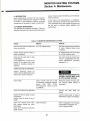
4-2 PERIODIC MAINTENANCE
The Maintenance Schedule provided in Table 4-1
describes the tasks that must be performed periodi-
Table 4-1 SUGGESTED MAINTENANCE ACTIVIES
Activity
Material
Remarks
Check all fuel lines for leaks and
loose connections
3/8" OD copper tubing
Fuel lines must be secure and free
of leaks, Replace tubing when
necessary.
Inspect exhaust lines for leaks or
loose connections
All exhaust lines must be covered
by a cloth insuation cover.
Check fuel for water and/or other
contamination.
If the capsule tank is used on the
Monitor 21 the capsule tank filter
should be checked, cleaned or
replaced.
Fuel color should be crystal clear,
if fuel is contaminated, see Corrective Maintenance procedure,
paragraph 4-9,
Inspect Fuel Pipe for obstruction
Inspect electrical wiring for
cracks, signs of deterioration, bare
wires and/or loose connectors
Clean heater
WARNING:
UNPLUG HEATER BEFORRE PROCEEDING. HEATER MUST ALSO
BE COOL BEFORE STATING.
Clean, lint-free cloth and a mild
non-abrasive household cleaning
agent. USE ONLY NONPETROLEUM
DISTILLATE
CLEANERS.
Wipe down exterior of heater cabinet. Vacuum heater interior (if
necessary).
Clean Air Circulation Fan (Monthly)
Vacuum
blades.
Inspect air lines for leaks or loose
connections.
Inspect rubber Air Hose at rear of
heater.
Look for cracks, wear, or signs of
deterioration; replace if necessary.
Clean fuel constant level Valve
filter. Inspect fusible link Valve
input fitting.
Clean only if necessary, Varify that
heater is level.
Clean Kerosene
fan cage. Wipe
fan
Refer to paragraph 4-5. Procedure
is described in paragraph 4-6.
Check Leveling Guide.
31
MONITOR HEATING SYSTEMS
Section 4: Maintenance
T
Remarks
Material
Activity
Inspect Combustion Ring, Flame
Sensor Rod and Baffle.
(Suggested freguency every 3
years).
Clean all carbon deposits. Replace
if excessively worn or cracked.
NOTE: If any gaskets are torn
when Components are
removed, the gasket must
be replaced.
Clean Combustion Chamber (every
3 years)
Vacuum all carbon deposits from
interior of chamber.
Inspect air holes in Burner Pot
Use a small, stiff brush or a short
length of soft copper wire to clean
any blocked holes.
Clean Igniter
Scrape any carbon deposits from
igniter.
Check air line that interconnect
Combustion Blower and Air Pressure Switch.
Replace air line that is worn, broken
or brittle.
Check for carbon build up in fuel
inlet going into burn chamber (every
year)
CAUTION:
If any obstruction is
felt remove igniter
before proceeding.
Disconnect copper fuel line from
burn chamber and clear fuel inlet
line by reaming with a phillips head
screw driver which should be able
to go in approximately "without
obstruction.
4-3 INSPECT EXHAUST/AIR LINES
Verify that all exhaust and air lines are free of leaks
and loose connections, as specified below:
B.
C.
D.
STEP1:
Dry all lines with paper towels.
Repair any leaks that have been found (if
necessary, replace the tubing).
Replace cloth insulation covers.
Remove Protective Cloth
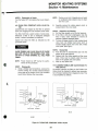
4-4 VERIFY IGNITER OPERATION
Visually inspect Igniter Operation
Remove cloth insulation cover(s) from all exhaust
lines.
WARNING:
STEP2: Inspection of Exhaust/Air Lines
A. Visually inspect both air and exhaust lines for
obvious cracks, leaks or loose connections.
Black carbon deposits may be evidence of
these leaks.
B. Be sure that all lines are installed tightly and
securely, especially at joints.
C. Turn heater ON.
D. Carefully apply a small amount of soapy water
(with a paint brush) to the surface areas of the
air/exhaust lines.
HEATER IS OPERATIONAL DURING THIS INSPECTION. AVOID DIRECT CONTACT WITH ANY
HEATED OR ELECTRICAL COMPONENT.
STEP1: Prepare for Inspection
Remove Louver Assembly.
STEP2: Visual Inspection
A. Turn heater ON.
B. Look (downward) through window on the Combustion Chamber. Verity that igniter is glowing.
Any leaks that may exist will be readily
identified by the appearance of bubbles.
If igniter does not glow, something is wrong.
Refer to the Troubleshooting Chart in Section 6
of this Service Manual to diagnose the problem.
STEPS: Return to Operating Condition
A. Turn heater OFF.
32
MONITOR HEATING SYSTEMS
Section 4: Maintenance
STEP3: Reassembly of Heater
Turn the heater OFF and replace the Louver Assembly.
NOTE:
4-5 CLEAN FUEL CONSTANT LEVEL VALVE FILTER
Contaminants are trapped by the filter to prevent
them from clogging the Fuel Constant Level Valve.
B.
Carefully remove the rubber gasket which is
located behind the cover plate.
STEP2: Inspection and Cleaning
A. Pull the filter straight out of the fuel reservoir.
B. If the filter is dirty (but undamaged), rinse the
filter in fresh, clean kerosene to remove all
particles. Replace damaged filters.
C. To drain off upper portion of fuel constant level
valve, back out phillips head screw which is
located slightly above and to the left of filter
cover plate. (See Fig4-1)
The filter, itself has a great number of small pores.
Whenever a filter is torn or disfigured (enlarged
pores), it should immediately be replaced.
Inspect and clean the filter as indicated by the
procedure below:
WARNING
STEP3: Reassembly
A. Push the (new or cleaned) filter back into the
bottom of the fuel reservoir.
B. Replace both the rubber gasket and the cover
plate. (Take care to properly align the screw
holes in the gasket and cover plate).
C. Wipe up any spilled fuel.
CLOSE FUSIBLE LINK VALVE ON M-21 OR CLOSE
SHUT-OFF VALVE OF THE EXTERNAL FUEL TANK
ON M-40 TO AVOID DRAINING ALL FUEL FROM
TANKS.
NOTE:
Position a six inch U shaped piece of metal
or cardboard under strainer cover to drain
fuel into a pan.
Power should be OFF during the performance of this procedure.
4-6 CLEANING FUSIBLE LINK VALVE INTAKE FITTING ON M-21
At periodic intervals, the fitting on the Fusible Link
Valve should be cleaned to prevent any accumulation of foreign materials from clogging the inlet. This
is accomplished as follows:
STEP1: Disassembly
A. Using a phillips head screwdriver, unscrew the
screws holding the rounded diamond-shaped
cover plate at the bottom of the Fuel Constant
Level Valve. Remove the cover plate.
Strainer
Cover
Drain Guide Container
Drain Guide
Container
M-21
M-40
Figure 4-1 CLEAN FUEL CONSTANT LEVEL VALVE
33
MONITOR HEATING SYSTEMS
Section 4: Maintenance
B.
WARNING
STEP2: Installation of New Fuse
A. Install a new fuse into the fuseholder. The fuse
must be a 250-V, 2 amper or a 250-V, 10 amper
type as marked on the printed circuit board.
B. Replace the Front Cover and the Louver
Assembly and plug the heater into the wall
outlet.
UNPLUG THE HEATER. POWER TO THE HEATER
SHOULD BE OFF DURING THE PERFORMANCE OF
THIS PROCEDURE.
STEP1: Close off Fuel Supply
A. Shut off fuel at the Storage Tank or remove fuel
from the fuel sump tank with siphon and syringe
if using the capsule fuel tank.
B. Manually turn handle to close Fusible Link
Valve.
NOTE:
Remove the fuse from fuseholder on the Printed
Circuit Board.
IMPORTRNT:
Place paper towels underneath the Fusible
Link Valve to catch any spilled fuel.
Whenever the heater is unplugged,
the Microprocessor must be reprogrammed when power is restored.
4-9 FUEL CONTAMINATION
Fuel contamination is often difficult to diagnose,
even though it will adversely affect heater operation
and performance. The best course of action to take
when fuel contamination is suspected is to examine
all of the system's fuel filters, beginning with the fuel
storage tank. If a Monitor Kerosene Lifter is part of
the fueling system, examine and clean that unit's
filter, as well as the filter located in the Fuel Constant Level Valve. When it has been determined that
water or some other contaminants have infiltrated
the fuel, the following action must be taken:
STEP2: Clean Valve
A. Loosen hex nut on Fusible Link Valve inlet
fitting at rean of the heater. Disconnect the
copper tubing which delivers the fuel from the
storage or the fuel sump tank.
B. Using a small, straight piece of wire carefully
and slowly ream-out the inlet fitting on the
Fusible Link Valve.
Avoid scratching the inside wall of the fitting.
With a cotton swab, wipe the interior area of the
inlet fitting.
WARNING
STEPS: Reconnect Fuel Line
A. Reconnect the copper tubing to the intake
fitting and tighten the hex nut.
B. Turn ON fuel at Fusible Link Valve and at
storage tank or fuel sump tank.
C. Check for leaks.
BEFORE PROCEEDING FURTHER, UNPLUG THE
HEATER.
STEP1: Remove Contamination
A. Shut OFF the fuel supply at the storage tank or
at the Fusible Link Valve.
B. Drain off the contaminants from the fuel storage
tank or the fuel sump tank (M-21). Fill with fresh,
clean fuel.
4-7 CORRECTIVE MAINTENANCE
The two procedures below are remedies for very
generalized types of operating difficulties.
4-8 REPLACEMENT OF FUSES
STEP2: Clean the Heater
A. Clean fuel constant level valve filter and filter
compartment.
B. Remove the Louver Assembly and Solenoid
Pump on the constant level valve. Clean the
Solenoid Pump filter.
C. On the Monitor 21, remove the Front Cover, Top
Cover, Front Bracket, Top Bracket, Combustion
Chamber Cap, Baffle, Service Panel and the
Flame Sensor, and then, remove the Burner
Cap and Combustion Ring from the Burner
Pot
On the Monitor 40. remove the Front Cover, Top
A short circuit or similar electrical malfunction could
cause the fuse to blow. Troubleshoot the cause of
the blown fuse.
Replace the fuse as follows:
WARNING
DO NOT REPLACE FUSE WHILE POWER IS ON.
STEP1: Removal of Fuse
A. Unplug heater. Remove Louver Assembly and
Front Cover.
34
MONITOR HEATING SYSTEMS
Section 4: Maintenance
-r
power to the heater.
Cover, Front Bracket, Service Panel and the
Flame Sensor, and then, remove the Burner Cap
and the Combustion Ring from the Burner Pot.
D. Using clean paper towels, thoroughly wipe the
bottom of the Burner Pot, the Burner Cap, the
Combustion Ring, and the Flame Sensor Rod.
If problem still exists and contaminated fuel is
suspected it can be checked by
A. Shut off the fuel supply at the storage tank and
at the fusible link valve.
B. Drain off fuel control valve.
C. Disconnect fuel line at back of heater and hook
up a 5 gallon quick tank with proven good fuel.
D. Test run heater to see if problem clears up with
use of new fuel.
STEP3: Reinstall Cleaned Components
A. Replace the components correctly and install
new gasket.
B. Turn on the fuel at the storage tank and at the
fusible link valve, replace all covers and apply
35
MONITOR HEATING SYSTEMS
Section 5: Servicing
of the unit thus it need not be cleaned. However, if
heavy soot built up does occur the unit should be
opened and cleaned.
5-1 INTORODUCTION
Servicing is required when the Monitor Heater is not
running at proper efficiency. This section covers
possible causes and corrective procedures for efficiency loses.
The burner is assembled using gaskets to maintain
its air tightness. If these gaskets leak, the extra air
can cause a serious soot problem and or exhaust
gases to escape into the area being heated.
Signs of improper heater efficiency and performance
would be:
- Yellowish lazy flame
- Smoke from flue pipe exhaust
- Heavy soot and carbon build up in combustion
chamber
- Lowered heat output.
NOTE: When cleaning the burner it is recommended to replace the gaskets.
If cleaning is necessary, use the following method:
1. On the Monitor 21
A. Remove louver assembly.
B. Remove front cover.
C. Remove top cover and lead wire connectors.
D. Remove front bracket and top bracket to
cover combustion chamber.
E. Remove combustion chamber cap.
F. Remove service panel.
G. Remove baffle from within combustion
chamber.
H. Remove flame sensor.
2. On the Monitor 40
A. Remove louver assembly.
B. Remove front cover and lead wire connectors.
C. Remove top cover.
D. Remove front bracket to cover combustion
chamber.
E. Remove service panel.
F. Remove Flame sensor.
3. Remove burner cap.
4. Turn counter-clockwise to remove combustion
ring.
5. Use wire brush to clean inside of combustion
chamber.
Vacuum and wipe clean with a waste cloth.
5-2 MEASUREMENT OF FUEL FLOW RATE
Fuel flow rates are preset and sealed. These rates
should not and we recommend they do not be
readjusted.
5-3 REMOVAL OF WATER DEPOSITS AND
CONTAMINANTS FROM FUEL CONSTANT
LEVEL VALVE AND FUEL LINES
NOTE:
1.
2.
3.
4.
5.
Disconnect the Monitor from power supply
(unplug) before proceeding.
Use a syphon pump and a syringe to drain off
any fuel in the fuel sump (in case of capsule
tank use on the Monitor 21).
If using separate tank on the Monitor 21, shut
off fusible link valve. On the Monitor 40 shut off
valve of separate tank.
Bend a piece of sheet metal or cardboard into a
U shape and place it under the fuel constant
level valve strainer cover to drain bad fuel into
a 1-2 liter pan. (Figure 4-1)
A. Remove strainer cover and drain.
B. With strainer cover removed, inspect, clean
and/or replace strainer if damaged.
C. Remove drain port screw and drain.
D. Replace strainer, cover and screw.
E. Open fusible link valve or shut-off valve to
refill system with fresh crystal clear kerosene.
F. Repeat steps 1-3 until all contaminated fuel
is drained off.
Remove fuel feed pipe from burner pot and
solenoid pump, and drain fuel into pan.
Once lines are clear, reconnect fuel feed pipe,
turn operation switch ON and start a test run.
NOTE:
6.
7.
8.
5-4 CLEANING THE BURN CHAMBER
Under normal running conditions, soot will not
deposit in great quantities in side the burner, and a
light covering of soot will not affect the performance
9.
37
Make sure all air inlet openings are clear.
If burner cloth on the bottom of burner is
deformed, replace it.
Combustion ring may deform and deteriorate
after several years use and should be cleaned
and inspected before reinstallation. If combustion ring is warped, has cracked or is deteriorating it should be replaced.
When reassembling the unit check that combustion ring is positioned with the correct side
up and is sitting squarely on all three support
screws inside the combustion chamber.
Reinstall burner cap and flame sensor to correct position.
MONITOR HEATING SYSTEMS
Section 5: Servicing
5-5 CLEANING THE FUEL INLET
When cleaning soot from combustion chamber the
fuel inlet pipe should also be cleaned. This can be
done as follows:
1.
Disconnect copper fuel line at burn chamber.
38
2.
3.
Push a phillips head screw driver (about the
same size as the I.D. of fuel inlet pipe) into the
fuel inlet pipe.
If obstruction is felt twist screw driver back and
forth (to brake up soot and carbon) so that
screwdriver ulimately penetrates to approx. 1".
MONITOR HEATING SYSTEMS
Section 6: Troubleshooting
39
MONITOR HEATING SYSTEMS
Section 6: Troubleshooting
Monitor 21/40 Resistance values
APPROX. OHMS
M-21
M-40
COMPONENT
16.8
12.7
97
97
824
824
1.3
1.3
4,600
4,600
68
91
Circulation Fan (M-40:WH & BK, M-21:RD & BK)
310
120
Circulation Fan (M-40:WH & GR, M-21:RD & YL)
365
190
Circulation Fan (M-40:BL & BK, M-21:GR & BK)
270
260
Circulation Fan (M-40:BL & GR, M-21:GR & YL)
210
200
22
78
Igniter (connector B/B)
Power Transformer— Primary (connector H/H)
Power Transformer — Secondary (connector L/L)
Power Transformer -Secondary (connector M/M)
Damper Solenoid (connector I/I)
Resistor (connector G/G)
Combustion Blower (M-40:WH & GR, M-21:BK & BK)
Combustion Blower (M-40:GR & OR)
—
Thermistor (connector Q/Q, at 77° F)
92
10,000
10,000
0.1
0.1
Fuse 10A (read with fuse out)
0.01
0.01
Solenoid Pump (coil)
688
695
Fuse 2A (read with fuse out)
WARNING:
DISCONNECT HEATER FROM POWER SOURCE
BEFORE MAKING ANY RESISTANCE TESTS.
40
MONITOR HEATING SYSTEMS
Section 6: Troubleshooting
Monitor 21/40 Component Voltage Readings
AC
COMPONENT
READING TAKEN AT
Thermistor
Q on PCS Sensor disconnected
Thermistor
Q on PCB Sensor connected
Air Pressure Switch/
Overheat Protector Closed
Connector J
110
Air Pressure Switch/
Overheat Protector Open
Connector J
0
Damper Solenoid
I on PCB
5
1.6-3.3
105
Solenoid Pump
K on PCB
Circulation Fan High Speed
GR to BK BK to RD (M-21)
BL to BK BK to WH (M-40)
110
110
Circulation Fan Low Speed
YL to RD GR to YL (M-21)
GR to WH BL to GR (M-40)
110
110
Igniter
'B on PCB
110
Power Transformer
(primary side)
.H on 'PCB
110
105
Power Transformer
(secondary side)
Connector L
Connector M
120
Combustion Blower
High Speed
F on PCB
110
Combustion Blower
Low Speed
F on PCB
(RL3 is OFF)
92(M-21)
88(M-40)
Resistor
G on PCB
18(M-21)
22(M-40)
1
41
DC
11
MONITOR HEATING SYSTEMS
Section 6: Troubleshooting
tf /
"0
oo
"D
~J
Tl
CD
Tl
01
T)
£.
•o
/
2S
/
/
/
/
TI
CO
1
•o
H
H
Tl
H
Tl
H
U
oo
-•g
cn
cn
•u
H
"0
A
-\
Tl
CO
Ol
3
p
CD
C
co
CO
ss
—.
13
C
3
CD
co
co
CD
o
o<
Ol
<
1+
O
^?
D
ro
l+
8
^
Fo
<
l+
00
o
vo
0^
I
(5'
13 13
C E.
(Q CO
3*
D)
•o
oo
i1 58
S
Ol
co
3
co"
(D
CD
M
i
(Q
2
o
13
co"
CO
CD
5
ro
13
3
co"
(D
p
co
co
P™
H%
&
O
CD
\p
cN
13
tn
(D
CO
co
f!
01 5'
y <Q
I? -
S
Tl
3
1
co
co
D
12V ±30%
Ol
3f
If
01 <Q
01 M
S
?5- ?
•n 01 cr
|i.3
3 ? l'
•A
(D
•o
3
p'
co"
CD
a>
42
co
S
on
<
l+
o
\°
0\
rv>
V±30%
§
ro
O
S
o
m
o
5V±10%
s
Waiting until
programmed tim
comes on
CD
CO
5
O
•n
Post-purg
co"
j§
5V±10%
13
0
CO
\°
o\
ro
<
|+
&
o\
12V ±30%
tn
CD
o
JS
12V ±30?
13
1+
5V±10%
5
infinitly
variable
5
co
Q
<
ja
co"
CD
l+
o
F
infinitly
variable
on
13
co
5V±10%
<*
on
13
12V ±30%
0
<
1+
m
3
%
r\3
o
E'
if\
Ol
D)
3
a:
s
infinitly
variable
1+
i+
—i
o %
\o
|
2.
12V±30%
13
0<
c'
CD
ro
0\
T)
Pre-purge
Pre-heat
5
i§
1+
12V ±30%
•o
(D 3
2V ±30
S
O =£
/
5V ±10%
Ol
/ S3
/ S 3
/ e
S
ao
SCH+A9
/
-•
/
a
///
/ o
/ 3
/ ?
/
I
/
^
O
5
_,, in
gina
^3 3
0 3 3 '
S • <o
ro
MONITOR HEATING SYSTEMS
Section 6: Troubleshooting
43
GENERAL CHECKS
Is power available in wall outlet?
Is power Plug inserted in wall outlet?
Has there been a power interruption? (Display
window shows 88:88;
Has Circulation Fan stopped?
Is fuel in tank? Tank valve open?
Has Fuel Constant Level Valve Set Lever raised and lowered?
Is Operation Switch on?
Is operation mode on Manual?
Is set temperature in High position?
is Fusible Link Valve "open"?
REASON
CORRECTIVE MEASURE
1
Replace or check Circuit Board.
Incorrect wiring of Flame
sensor or Ground.
1
Flame sensor rod touches
to burner parts.
Correct or Change.
Failure of Air Pressure Switch.
ReP|acs Air Pressure Switch.
lilure of Solenoid Pump.
Replace Solenoid Pump.
Failure of Combustion
Blower motor.
Failure of Circuit Board
1
1
Correct wiring.
Soot adhering to combustion
chamber interior.
Replace Combustion Blower
Motor.
H
Replace or cr
Circuit Board.
•"^^•J
Correct wirirtc
H
Clean gently with brush, etc.
REASON
CORRECTIVE MEASURE
Fusible link valve closed on M-21.
Replace handle of fusible link valve
or open valve.
Rec lace Fuel constant level
valv e.
•• Failure of Fuel constant level valve.
Burner joint clogged. (Fuel Line
passageway into the Combustion
Chamber near base of Burner Pot.)
*•< Fuel not fed because or sunase
I tension of water.
[!
'—I Water gathering in fuel tank.
4 Failure of Solenoid Pump.
J Clean burner joint
—«
I
-„
M-E
LJ
JH
!H
Replace Solenoid Pump.
Correct or replace wires.
Straighten fuel line to remove air
pocket, or, correct fuel line
installation.
Extinguished
soon after
ignition.
Is Fuel constant
Level Valve
Lever set?
Fuel not entering into fuel.
Push Fuel Constant Level Valve
Sat Lever 4 or 5 times.
Fuel shortage.
1. Push Operation Burton to "Off"
2. Refuel talk.
3. Turn heater on.
1. Unplug heater
2. Remove air flow obstructions and
or determine cause of overheating.
3. Replace cover and restart healer.
Overheat condition.
Flame does
not increase
Make General Checks above.
* is fuel head too low?
"High"
« |g fuel line lenath correct?
•
.^M—4
Normal,
|—
is solenoid
pump High
[Correct fuel line.
Is unit placed horizontally?
r
w •mg
LJ Failure of solenoid pump,
f^~~ Replace solenoid pump.
™| Failure of circuit board.
r™™ Replace or check circuit board.
Correct as specified.
Poor flame, sounds of comneator.
_J
tighten all connection.
CHECK1
SYMPTOM
Smoke proset -High.-
"•
Is a unit
| RESULT |
• 4
Normal-
^™
zontally?
CHECK2
Does
| RESULT |
CHECKS
|
| RESULT |
CHECK4
j RESULT |
CHECKS
| RESULT |
Failure of Damper Solenoid Assy
i
_^
1
<=~lon«j,1 vunrW
1
CORRECTIVE MEASURE
REASON
L— ^J Replace Damper Solenoid Assy.
f
properly?
Fan
Is flue pipe
too long or
have too many
Check for
obstructions
Sections.
INSTALL)
•4
Normal,
nests) in
i
1
is igniting
time too
igniting.
(Usually 0.5-1
min.)
-1
Normal,
t——
i-—J
ls Air
installed
for flow Of
anr-nrrting tn
Ves.
^^ Fuel solenoid pump malfunctioning.
""™4 Replace solenoid pump.
1
"specifications?"
| 1
r[
1
__ Install Air Damper according
^^T
^—^^
i Lji"-jimd- ™l\"~
i
Combustion fan failed.
L
f— •— Replace Combustion Blower
Clogged air supply or exhaust piping. — •^^ Remove obstructions.
^^
P
""
1
Combustion
noise is made
~
^fH
Pipe
air and exhaust.
supply piping.
1
r^— Check outside
r~"
i
1
Normal.
1—
i
Too much air flow.
Is air damper
t—— Mount Air Damper
specifications?
M
Normal.
1— | See Symptom gs aDove.
Mount properly.
Combustion
Chamber
Is fuel a pure
kerosene?
smoky after
Is Heater
9
rl Nomal H
Does flame
externd to
1
1
Drooerlv?
Combustion Ring is installed
improperly.
1
L
of burner?
horizontally?
-t-ls external
fuel tanK too
low? (See
Sections.
L ; L_
Install
Air Damper,
if needed.
(See Symptom
1
1
to Hioh and Low 5-6 t mes.
1
— —^ Install Combustion Ring properly
r
Air leaks from Igniter Cover.
II
fu 1
due to dust or bubbles in Fuel
_ _ Replace gasket; correctly install
cover.
reset lever.
Is there an
the Combustion
Air intake
-J
Sy
"—'• h
Flame does not extend,
t-
• Failure of solenoid pump.
I— —J Replace sofenoid pump.
9.
[ SYMPTOM |
CHECK1
| RESULT |
The Overheat
Thermostat is
activated.
Is window
curtain too
close to the
rear of unit?
Yes.
Is Circulation
Fan Guard
dusty?
CHECK2
! | RESULT [
CHECKS
| RESULT
REASON
CORRECTIVE MEASURE I
Curtain or other obstruction
covers circulation air inlet.
Clean guard.
Keep curtain from unit.
Does circulation fan operate
properly?
Yes.
Obstacle covers circulating
air outlet.
Failure of P.C.B
1
Remove obstacle.
H
Replace or check P.C.B
Circulation fan failed.
Replace Fan Motor.
Incorrect wiring.
Repair or replace wiring.
]
I RESULT |
|
CHECK3 "]
| RESULT |
| CHECK4
[
| RESULT
CHECKS
REASON
)
| CORRECTIVE MEASURE~j
1
J
{
NOTfi If problem is found to be in PCB,
do not attempt to repair, replace
and send PCB thru your distributor to MPI for repair.
^^
j "
Failure of Tfansfcrmer.
_
~
Replace transformer
1
Failure of Diode
D4-D7>.
-
Replace Diode.
1
Failure of Capacitor
—
Replace capacitor.
|
l^^^^^^
TP1^
"
eplace 1C.
'
L
^^^^^^J
does output of TP8
Failure of Capacitor
(ClOi.
I l^^^^^^^mj
processor HCl).
L[
Failure of com pa rat a
„.
j
1
Failure of resistor
tR22, 23.24,32!
Failure of zener
diode (ZD2!.
L(
~\j
1
J
tv i Fr>
««
|
I
Failure of Copacitor
(C211.
Replace capacitor.
1
Replace comparata.
1
t
Replace resistor.
1
-
Replace zener diode.
I
Replace capacitor.
1
Replace capacitor.
I
Replace operation circuit board.
I
-
Replace resonator.
1
-
Replace resistor.
1
Replace microprocessor.
1
~
1— 1
-
^
^^^^^^^
""
1
,
,
|
T2 pin and T7 pin on PCB.
L.
I
1R17. 18, RJ202i.
Failure of capacitor
(CIS).
L
~
1
•j
No.
r™~"
ls
temperature
n v
m
—pi
No.
p™ Does heater
•_!
Yes.
.— ...
|
LJ
No
l—i-
Failure of operation
circuit board.
Failure of resonator
iXLi.
Move the Timer Sale(C31, 32 1.
Failure of resistor
(H461.
(
Failure of microprocessor (iCI).
-
| SYMPTOM |
1
[
No Ignition
p- Is igniter red
on preheat?
-i •J
'
No.
RESULT |
CHECK2
RESULT
CHECK1
|
h
s there !2Vdc
at coil of relay
' RL1 ) on preheat?
I
CHECKS
| RESULT |
| CHECK4
|
| RESULT |
CHECKS
|
RESULT |
REASON
1
Failure of microprocessor ICi .
-
L
•Ma
ves
I(-
Failure of IC3.
F '1
(RL1).
CORRECTIVE MEASURE
H
-
Igniter open.
during prepurge
and igniting?
s there i2Vdc
at coil of relay
RL4) during prepurge and
Replace fuse.
—
;
Failure of relay
(RL4).
_
Failure of combustion
blower.
Incorrect wiring of
combustion blower
Failure of resistor
for combustion blower.
~
In correct wiring
of resistor
—
-
Rubber hose is
bloked on
discorrected.
L
Incorrect wiring.
Replace combustion
blower.
correct wiring.
Replacs resistor.
correct wiring.
ure switch.
pressure switch.
Does air ressure
switch work normally?
rS
Replace igniter.
Replace microprocessor.
processor (101).
TJ—!1—I i
Replace 1C
f rel
Fuse tF2) Open.
Does combustion
Replace microprocessor.
—
-
Clear and Of
correct rubber hose.
Correct wiring.
SYMPTOM
CHECK4
Is there 12Vdc
at coil of relay
| RESULT |
•
1
V
**
i "
CHECKS
Does solenoid
| RESULT |
•j
No.
REASON
1—
|
CORRECTIVE MEASURE ]
Failure of relay
1
Replace relay,
Failure of diode
(D2).
1
Replace diode.
1
during igniting?
igniting.
H1
1
L
4
H *• h
Is transistor
(Ql) ON during
igniting?
J
Yes.
Yes.
-
f"
1
I-
L
I
H N* r
—
Failure ot solenoid
pump.
^—J
Replace solenoid pump.
1
Failure of fuel
supply parts.
^—J
I
Check fuel supply
parts.
1
1
Failure of microprocessor (IC11.
*H— 1
Replace microprocessor.
1
I
1
Failure of IC6.
1
Replace 1C.
1
Failure of diode
(Dia;.
1
Replace diode.
1
Failure of IC7.
1
Replace 1C.
I
•J
Replace 1C.
1
Replace resistor.
I
Failure of 1C
(ice, iC3).
-
Failure of resistor
i.R48).
••^•J
-
Failure of transistor
(Qi<.
— HJ
Failure of diode
(011).
•
'j
Replace transistor.
Replace diode.
1
1
CHECKS ~[
[ RESULT | | CHECK4
RESULT
| CHECKS
CHECKS [
RESULT
REASON
Failure of resistor
rR4. R5, R6. RJ20H.
1
1
Failure of transformer.
-1
stop heater operation, and
connect equivalent flame circuit
between flame sensor rod (O P'nl
and ground i[Dj pin)
Equivalent flame circuit
CORRECTIVE MEASURE
P^"™1
Replace resistor.
-i
Fuse i.F3i open.
-L
Failure of capacitor
(C14. CIS).
Failure of resistor
(R1.9.10.X201 ,56.57).
Failure of comparator (IC2).
Replace capacitor
Replace resistor.
^•^J
••••••J
Replace comparator.
Replace resistor.
(R51).
^
I
Failure ol diode
(D16K
•J
1
Failure of capacitor
IC37;.
—•!
Failure of IC5.
L
1
I
1
""•i
F
I
Replace diode.
Replace capacitor.
Replace 1C.
Failure of microprocessor.
"•"••I
Replace microprocessor.
—
Failure ol wiring for
flame sensor and ground.
•^••J
Correct wiring.
—
Incorrect installation
of flame sensor rod.
^"^
Correct Installation.
^
J
I
1
1
1
I
1
1
1
CHECKS
j
[ RESULT |
|
CHECK4
|
| RESULT |
|
CHECKS
|
[ RESULT |
I
I
Is circulation fan
L-
change speed?
1
1
"
1
"
1
. ...I
Replace resistor
L^^^_
Failure of solenoid
I
1
Failure of relay
,HU,.
1
Failure of IC6.
1
Failure of circulation
fan motor
^_^J
1
Failure of relay
(RL3,4,5>.
-1
1
.r
1
~I
I
1
—J
Failure of 1C5
1
Failure of combustion
blower.
^_^J
|
I
Failure of clamper
solenoid.
>4
^.^J
1
'R2 . zener diode ZD2 1 .
L
!
I
rnv
2.8V at IC1
1
N
°
l~
Replace solenoid pump.
Replace relay.
Replace 1C.
Replace circulation
fan motor.
R8Dlace relav
nopiacoiuay.
Replace IC5.
Replace combustion
blower.
Replace damper
solenoid.
zener diode.
Failure of capacitor
(C10.C38) .
i
L
r™"
i__^
—[r~
CORRECTIVE MEASURE
1
Failure of resistor
[R47.S2 S3R4,fifi1
L_
] [
lira in nv
~•
Connect 1QKfl resiator at |Q) pins, and
then, set temperature
from Low to High.
REASON
Failure of capacitor
(C11.C12).
—1
1
M
Replace capacitor.
R 1
ssor.
MONITOR HEATING SYSTEM
Section 7: Electrical System
Printed Circuit Wiring Diagram
CONNECTION OF LEAD WIRES
T8
OD
T9
-•—
TIMER
SELECTOR
OPERATION
'
TIME
TIMF a
'
TEMPO ^
TEMP SET
a aa
Panel Printed Wiring Board
1
2
3
4
5
6
-H
i
1
i
1
BURNER STATUS
I^T I I I
f l / / /
-l
TEMP
AM
P M
SET ROOM
"1
1
Lamp Printed Wiring Board
fl
ri_
T?
T3
S T4
TFi
T6
~a~
b
c
(j
e
f
t_g
DC12V
Sensor (Thermistor)
I
l2J
RP~~1 Flame Detector
Power
Cord
Fan
Thermostat
Blower for
Combustion
figure 7-1 Monitor 40
52
MONITOR HEATING SYSTEMS
Section 7: Electrical System
Printed Circuit Wiring Diagram
CONNECTION OF LEAD WIRES
T71
T8
TIMER
SELECTOR
OPERATION
TIMPD
TIME/TEN
TEMPd
T9
1 —1 1 —1
1
[===
'
1
1
1
q
Panel Printed Wiring Board
~l— _
*—
1
2
3
4
5
g
CC"
m.N AMTn PMPTY
R
BURNER STATUS TEMP ±1
' ' ' i*
'
-=-
Lamp Printed Wiring Board
—^
c C12V
M —
AC 120V
•to
- J —
i—-}_
Main Printed
Wiring Board
K
Pump
1—i ^ort
U
m i* « • i
d =M
f
r— n
u
^F
—
1—PI
-* ,
b
—J
r
ROOM
PM'
T3
T1
T51
Tfi
S
—••
r
-^
(Float Switch)
Ul
AirT
Pressure
Switch
J
L°£]
o
0
—y—<^-^
fl s-j-v
-c=HZ3-
ES |
3ver Heat
Ther nostat
E
- 'H
H
|
pi
G fo]
lo|
E
D c
El IJlEg
B
Res istor
1
lul
'
^J~
—
.1
^
—
n TT
""
Blower 1 or V
Combus tion
I_E|
D
1 °'ower
Circulation
C
Fan
Thermostat
figure 7-2 Monitor 21
53
1 Flame Detector
~~1. Ground
f«^ •
foi
E
*
Junction Box
T
n~ i i L%fli 14 -n_
F
*—U—'
A
Power Transformer
C
Sensor (Thermistor)
L
DD DDD ' ®*
t —
\ —
s<)leno id Valve
feu
M
B
~S Heater
fc-
r.
Power
MONITOR HEATING SYSTEM
Section 7: Electrical System
Schematics
54
FAN THERMOSTAT
'
•'
MONITOR HEATING SYSTEM
EXPLODED VIEWS AND PARRIS LIST
55
40
1
)
87)
Carton Box
Cushion Set
[89)
MONITOR 40 EXPLODED VIEW
Owners Guide
MONITOR 40 SERVICE PARTS LIST
NO
•i
2
O
g
!0
ii
12
13
14
ir
18
19
20
71
PART
NO.
5300
5185
6301
6302
6303
5304
•S 3 0 5
5305
6307
6303
5309
6310
531 1
5115
6 1 17
6312
6119
6313
6314
6122
6123
6176
7 t;
95
7
5125
•5069
1
1C
6313
3'1
32 6319
33 6320
?4 "5321
3 5 5 39 2
35 6323
r "! 4 9
6324
5 " -1 -1
42
43
44
45
46
-1 T
6135
5132
6326
5343
51 3 6
5327
•6 1 52
6137
5032
6139
DESCRIPTION
SPILL TRAY
LEG
AIR SUPPLY HOSE (A)
AIR SUPPLY HOSE (B)
CONSTANT LEVEL VALVE
CONSTANT LEVEL VALVE
C
UEL PIPE
'SOLENOID PUMP
BURNER
GASKET (2)
GASKET (2)
HEATER
GASKET (3)
HEATER COVER PACKING
FLAME DETECTIVE PLUG
PLUGPACKING
GASKET (4)
HEAT EXCHANGER ASSY
GASKET (6)
EXHAUST DUCT
n _ p i M n £ p 3 g "\
ITEM
NO.
52
53
54
55
55
STRAINER 5"?
58
59
60
61
6.2
53
64
55
56
67
58
5Q
70
71
72
^3 74
75
76
OIL SUMP PIPE
JOINT SEAL PACKING
WINDOW GASKE T
WINDOW FRAME GASKET
WINDOW PL ATP £(//uj>eu> ,
W T NDOW GLASS
WINDOW BASE GASKET
CHAMBER GASKET
COMBUSTION CHAMBER ASSY
COMBUSTION RING ASSY
BURNER CAP
CHAMBER CAP;
C O N DENSE R'" ( 2 . 5 ) MFD)
B!OWFR ASSY
T n f\| r .\ 5 c A ,\ 2 c v
g SPACER CLIP A
3PAOER CLIP (B)
POWER TRANSFORMER
AIR LINE
AIR PRESSURE SW
RUBBER BUSH
OVER HEAT PROTECTOR
PAN THERMOSTAT
COPD CONNECTOR
JUNCTION BOX COVER
POWER SU°PLY CORD
„•
.'
7:a
79
90
81
82
83
84
35
86
87
83
39
90
91
93
93
94
95
96
97
93
99
ion
101
102
PART
NO.
4833
5037
6138
6186
4004
5328
5.329
5145
4014
4015
4006
4008
4805
6147
5148
6075
6330
6331
63,32
6333
5334
5335
6336
5154
DESCRIPTION
CORD BUSHING
LEVEL GUIDE
CARRYING HANDLE
SENSOR ASSY
JOINT PIPE
AIR DAMPER (E)
AIR DAMPER (S)
AIR SUPPLY HOSE ASSY
EXHAUST OUTLET CAP
A I R PORT O PING
D
IPE HOLDER
HOSE BAND
AIR OUTLET CAP
FLUE PIPE ASSY
SLEEVE FLANGE SET
FAN
CIRCULATION MOTOR
BLOWER GUARD
UNDER COVER
LOUVER
CONTROL COVER
FRONT COVER
LAMP PANEL
SWITCH ASSY
5155
L A M P ASSY
6337
6339
5339
6157
6168
6169
6171
6172
6173
5340
5341
5342
! i 43
TOP COVER
RESISTOR
CABINET ASSY
MICROPROCESSOR .'M^n940xR E!_ .A Y ( A )
RELAY (B)
B UZ Z E R
FUSE (250V 10.A)
FUSE (250V 24)
CAPACITOR (1.3MFD)
CARTON BOX
CUSHION SET
OWNERS GUIDE
S187
IC3 M54563P
5138
5190
i c 9 - i Q - i i PHOTO COUP! PR
BASE TRAY R E T A IM F P.
6194
6195
6196.
WALL CLAMPS
IGNITER BRACKET
FLAME ROD BRACKET
6197
6344
5345
SCREW SET FOR FLUE PIPE
STRAINER GASKET
UNION NUT
56
5345
IGNITOR COVER
6347
5343
8216
W I R I N G GUARD
MOTOR FOR COMBUSTION =M -^TOUCH-UP PAINT (WHITE;
I I
(75)
Carton Box
(75)
Cushion Set
(77)
Owners Guide
MONITOR 21 EXPLODED VIEW
MONITOR 21
SERVICE PARTS LIST
MONITOR 21 SERVICE PARTS LIST
ITEM
NO.
1
2
3
4
5
6
7
8
9
10
11
12
13
14
15
16
17
18
19
20
21
22
23
24
25
26
27
28
29
30
31
32
33
34
35
36
37
38
39
40
41
42
43
44
45
46
47
48
49
PART
NO.
6100
6101
6102
6103
6104
6105
6106
6107
6108
6109
6110
6111
6112
6113
6114
6115
6116
6117
6118
6119
6120
6121
6122
6123
6124
6125
6126
6127
6128
6129
6130
6131
6132
6133
6134
6135
6136
6137
6138
6139
6140
6141
6142
6143
6144
6145
6146
6147
6148
DESCRIPTION
SPILL TRAY
AIR SUPPLY HOSE A
AIR SUPPLY HOSE B
FUEL PIPED
FUSIBLE VALVE
CONSTANT LEVEL VALVE
CONSTANT LEVEL VALVE STRAINER
AIR LINE
SOLENOID PUMP PACKING
SOLENOID PUMP
OIL SUMP PIPE
FUEL SUMP
GASKET (1)
BURNER CLOTH
GASKET (2)
GASKET (3)
HEATER
HEATER COVER PACKING
FLAME DETECTIVE PLUG
PLUG PACKING
GASKET (4)
HEAT EXCHANGER ASSY
GASKET (6)
EXHAUST DUCT
WINDOW GASKET
WINDOW FRAME GASKET
WINDOW BASE GASKET
COMBUSTION CHAMBER ASSY
BURNER CAP
BAFFLE ASSY
CHAMBER GASKET
CHAMBER CAP
POWER TRANSFORMER
PWB ASSY
PWB SPACER CLIP (A)
PWB SPACER CLIP (B)
PUBBER BUSH
CORD CONNECTOR
CARRYING HANDLE
POWER SUPPLY CORD
BLOWER ASSY
BLOWER MOUTH PACKING
DAMPER SOLENOID ASSY
SUCTION CASE
SEAL PACKING
AIR SUPPLY HOSE ASSY
AIR DAMPER
FLUE PIPE ASSY
SLEEVE FLANGE SET
58
ITEM
NO.
50
51
52
53
54
55
56
57
58
59
60
61
62
63
64
65
66
67
68
69
70
71
72
73
74
75
76
77
78
79
80
81
82
83
84
85
86
87
88
89
90
91
92
93
94
95
96
97
98
PART
NO.
6149
6150
6151
6152
6153
6154
6155
6156
6157
6158
6159
6160
6161
6162
6163
6164
6165
6166
6167
6168
6169
6170
6171
6172
6173
6174
6175
1142
6176
6177
6178
6179
6180
6181
6182
6183
6184
6185
6186
6037
6068
6069
4004
4805
4006
4008
4014
4016
4833
DESCRIPTION
UNDER COVER
LOUVER
OVER HEAT PROTECTOR
FAN THERMOSTAT
FRONT COVER
SWITCH ASSY
LAMP ASSY
TOP COVER
LAMP PANEL
FUEL TANK COVER
FUEL TANK ASSY
BLOWER GUARD
CIRCULATION MOTOR
RESISTOR
AIR PACKING SET
JOINT SEAL PACKING
FLOAT SWITCH
CABINET ASSY
MICROPROCESSOR (M50940)
RELAY (A)
RELAY (B)
CAPACITOR (1.5MFD)
BUZZER
FUSE (250V 10A)
FUSE (250V 10V)
CARTON BOX
CUSHION SET
OWNERS GUIDE
0-RING (P39)
OIL FILTER
FLOAT SWITCH PACKING
FUEL TANK CAP
FAN BLADE
COMBUSTION RING ASSY
BURNER
JUNCTION BOX COVER
AIR PRESSURE SW
LEG
SENSOR ASSY
LEVEL GUIDE
WINDOW PLATE
WINDOW GLASS
JOINT PIPE
AIR OUTLET CAP
PIPE HOLDER
HOSE BAND
EXHAUST OUTLET CAP
AIR PORT O RING
CORD BUSHING