1
X.
5§
E:i
‘=;.f
"=»&e1\~:==e".’_
g_N<';¢ ‘Q15?-mi”
<;:;<€~_{a<2r*<:>
Q"->‘=.=:»~':;"'
T?{x¢:1rEf.~.;1;:» §>~“lt:»
Q!
<:t>:-\*».;~—s
»|
" @‘\€_“">~=:."@...
._~.,»_w.-»,¢_~».-
W
:,._
--, _ , ‘#1, :3 T31; ., ;1’€ ‘iggn.
'- $/12:14 1-< 1;‘
Q
.
1\‘?5?§i‘
~‘
21$.
-». -13:L%1!<;-
‘‘¢*1;1v<‘‘ \-T
"41
_ "
'~-
¢§~
141
'3'?
wfifigfifi Qgfiaagfig
‘
If
.
» T
'9
SEEWEE NEMQQM,
_.,,
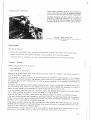
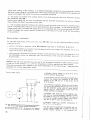
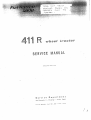
Service
nenartmeni
Via Canap,;;1,3 - 8tupinigi A- Torino (Rely)
Fm.-n
ED3_5d.5B~3 - Aprfl, {Q63 .. 2000 ~ 5. A.N. - ‘Fcrino
1
|_~m$‘)>_'|I£fill
.;E_¥s>|l‘V;m_iv:|_;i>;_vm_ >:_
_h
_%_I;
fitf
_
\flMi
V
A@_M_AflH§_P\=I‘'_t1.{‘MI“!l“|___‘1]irtEI!_miHsi;%@1_|wHa}EHMHV» W
*
J
gm
>
E
A)
W
M
Jb
_fi__
m
_‘(
WT?
Iv¢___w“
¢
/‘if:
1 lm%!d
AW
I
___,__m,)1I_vV
‘__v:_M6
_|J
,__’l‘_
_'fi_A_“_'JI'7
_'_‘__‘1*‘
*‘____‘”E_5_qw_p
1_'M
_“N__
E"
“‘| 1"‘ H‘
_A
__/as
_‘_ _____
_
IW
Q
“\‘ K\agfimfikpfi
lg'u5%ah“:
K_E__$
~\flaw
_?A_ _
_1/M_F”‘mv
_‘
_{A
5/E%/\
i
fig“
w
$
‘In.
K3
_A
4“
H‘~‘~‘
[AW
Ii\_‘ffi’
‘
gm“;
m~__
“}_ki_g§
X
_ qllédfllj
R_ _ ‘X‘_i_H_‘£_!EAH_I1JH
L_,~N|M|V4”//I
Hu{Vfi/1%’?
_’ ,/6km")
F’
1:‘;I1}P‘
fJ_,
'_E‘ll>11 ‘_lJ9
La'_h/VF...’
_
"uW
Eé_asumm
U¢°3mmam
m"_‘___w
_ w°_:w_ P
M
/IQ_/Ru_Mi
fix
%\ \
52
t\ \
‘in
(1
»-.=
5...
9.;
;.
l
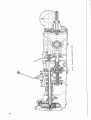
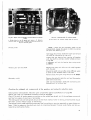
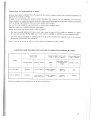
TRANSMISSION ASSEMBLIES
.l- W-._»,~_
CLUTCH
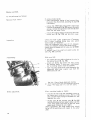
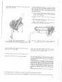
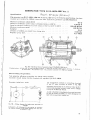
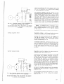
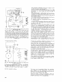
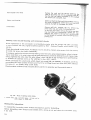
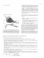
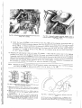
The master clutch assembly is composed oi two dry, single-plate clutches, one for the tractor transmission
drive and the other for the power-take-off drive.
The unit is controlled by one single pedal which, during the first part of its travel, disengeges ihe main
clutch (transmission) and En the following one, the power-take-off, but only when this attachment is
directly driven by the engine (independent powewtake-oh).
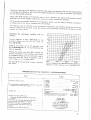
The three diagranns of Fig. 82 illustrate, respectively:
a) the clutch engaged; ii) the main clutch disengaged; 0} clutch completely disengaged.
€l¢i{}[$£t_
‘
Nu <l:zrin::
III
L ».
~'
i '
' »
i
‘* Ali! ’
:~\\\§-:l
X;L
,--—-i
..
'0
'@"
l L 1"?
\ i l
~ e I
-
I ,
/ ./1-r,:_*'fC<//
.,
'
2'2/f
at //.0
§
'
______,,__
'
"M \
//",/*__/' -'
,
|
;
H
)7 ‘;\.\§§\.-E
./fr _
».
,<;L".\
|
3», - ,=
.' . .'
JH P
"n
'
.
‘
'
1-
ifi
I
a
I
__\v:L@(
,L_
i‘
.
;
..
-“F
L
/W/ )3?/”J<”‘
‘~‘:2.1-*i'_‘
iv;
kl
"’.’/ ;_/,.-'z*'=:\-I1.
e f imlli 2%;
('3
s /Tit;
1""
D‘
,1
I-41
_, '
W-
.
gig,o 1
-
_
Q
‘
5 //'l
,_=w-.
—
I
"1;§‘
,
“‘K:
*- -__§}
..
,,
,_..1_ ,,__.-'!:.,...._;\
l-—""
Fuureuu
Q. *1;; *-aI:~—~
__
5
'
F‘
§_ ,
,
‘
i
~ . .
A MaulT?
I
._é:
;m'~
1- ~
,
'
1
.>‘F)
;
\_»»-I
1
Fig. 82. - Clutch functional diagram.
a - engaged clutch.
b A main clutch. disengaged.
4 I
I
c - clutch, completely disengaged.
F we Power take-off dm-en plate - C = Gearbox driven plate - P = Lever points.
l
I
>
I.
-1
\
1
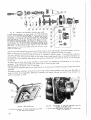
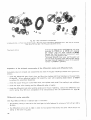
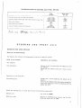
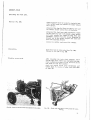
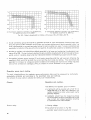
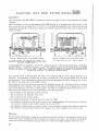
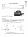
Removal and stripping of clutch.
Removing the clutch assembly from tractor:
Paris to be removed.
i
Operations and cauiions.
The batteries.
The exhaust pine.
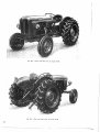
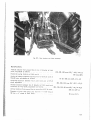
The engine, with the front axle (Fig. 83}.
‘
Disconnect the following components:
1
'
»~— the hydraulic pump oil lines, the steering shaft
lever longitudinal iie~rod, the board‘ from the bailery
1
J
I
support and this support from the gearbox case, the
accelerator pedal fife-rod from the transmission shaft;
the electric cables central connection;
~»— firf two‘ wooden wedges on the froni axle, attach
the engine assembly to a lift and place the gearbox case on a stand;
¢— remove the screws assembling the engine to the
gearbox and facilitate {he removal by acfuatlng
the clutch pedal.
"
.
Nofie. - To pull the flywheel inner pllol bearing
use fool A 619827.
Fig. B3. - Removal of engine, with front axle.
53
-._-. -_0. _.i-<~\.-»,. ._-i
i
[
‘W
~,§‘i"?
"!§;L
ilfi
5'".-'
"
3: --J‘ '*.w,.;"-J
‘ “
‘
-
|‘ .
_
.
E _ -_
;-:'
"'~
w
‘
_ ~
‘=
'
.
.
2
b
'
’ 15$.2”.
v
‘=5
' A
—
‘
,.
‘ _V _. 7 _
‘ '~ ~~
'
_~'
__
"\
p--- 1.
‘i3 ~'I >~-4 :='&»''
7-
:1,.;%,=':1.<:=¢,r1:‘.-2;:..=§.=;1 .4
7‘ "-"-»j - 1' '
:1-..> ;'-'-5-‘_.
;.<‘::'1'¢"—»;,.'-}=a*.£-;¢;“
‘ a ;;.’;,.,Q.I‘..‘,""'"
'
-;’f'§.. .___1~* -~
;
L
-‘$=£:'-‘>1-..',;‘:“,i-;fi'~'_f3
2‘-:5, ~;1,_-=:‘__:'_‘
-_:J\_|h-‘».~_;_
-1,.
1%a..-,:=..~
,_._=_._7,,
=1 -»‘
1-.-. _-...—___.,,.,
F -'___.4§'vm_:-_1;:1-&<{5;t~
rd"-36
,_.‘
~- - V — "h~-‘
*~
‘2:;=r.~~"-.'-2;-_#=1:,
'
-- .
. ' 1»
*1 =,"_-J-',.:-—;
"K. .. .9‘-V
. ;;; ,~:;
'
...--. '~.=.»=.;.- &,~~'
1'4‘.
- =;;;‘~:~::.
"ii
’
, J
'~I='i-"
'*£:i£"-.'.:'§:
. '
'
1'
_. .,
.=’
A " “
-‘“"’%:=;‘,4
;-.-- ; '
"A:
‘- ‘ ~
5? :1 *-: """ ‘ < 5"--.~~ ‘=‘
all
,;.-‘/-"0=2"5L:Ki’;-;$i"e.1=‘="'<:§2.':"2’1‘l11'
'¥= 1- "
‘ ‘-.. .3 .1--,1
ac:-;;¢=.-";I=—-‘i;:1~.*."§We-1*'
~ '
"Q
’»
,4?“
~
_:-.-L:;.2‘ii=¥'.%'s¢;*1»;@=.¢&~1f5“*%!1¥=*f-A".fi;;€:#
-.— ‘- .~. 1..
;~+._
"~“"5'-.'fi"L'¢?i5€?"'*=’%€‘@;£1.&v*‘.‘§*u_%1€3"‘ ‘ 1»-X-~:
.‘i’-;'--
''7? J’-?Y_<:'1‘.T","!f':‘,5’?
Y
_ . a;-'1.=j=
<1 1-)1-'—::"~‘i-;:Z,1=1r,;<:.
,
I-. -
41,H._-.
\ L‘'
_
~
-
‘
.
'
. , "
“'?$‘:::“
‘:1-,»
‘. .
.; _ ;,;r\>,
_‘
..=.§g
K
J=*~~.~=~“ -
_fi~**_;,,..-.,‘.1
.!i=‘-1-"
.. ._
\
' '_
-"
_~..
.'-'- 53::-=
. -.,
-,1
..M
"
‘
l_41_".:?1’
-‘
Hr ' .~F
-,':I~<;'lv='-:":'T:<*I_,=1-_=.. -~
: -
,
-.'5'.~
'
:11
=1“
a»
--
.,..
'
_ . ix‘,
wk
. _
-\
"
‘ :“-- =' -~
5:-.-gé
' F.~. -
i‘?'4-’ *'
_‘ ,_ _ __
_
:,=
.,:~»- .-.
7--V'§§.§:"a‘L‘,‘ '
_
“‘
- Q '#;{ZIi(’§-g§-x
1-_
la '
Q ‘J <11-_'~
Si’
in
.
.
= 1:‘
=-'¢;‘i;;
.
=
_:_~
a -- "~
'-' ..
;:= ~,:. ;
-TF1‘-1.'€.‘.:
=
"
3‘ L ‘£:_
'._{,___.;_“ , .-1 ¢. , - ._
L
‘
(4
K =1.
*~'---' ,- t
'
J5,
“ .-.'.=_-~.1."=.;<”:-a-111:2-'_:,§'..=i_'‘fly. Lt: ,1
=
A’ . I
_ _: ~_‘;.F_‘,_:,%€;_:i,;,:€M_..E..
'-'—'"-".
.‘;-':-
1 ,.
.. ,_
..
_
. . . . .
.
'- -. - “ 1
,1
.»-1;--‘-'._:-'
._e'=--a=7p¢;.;:-‘=.=' ' '- LI
;"'_.I‘_
“"'
-“':
Y"
I,-.;~<_;_'. ='
. I,-.,, -‘' ;Z'3‘**:
..-a_-.-=.~w-a1?.
'
.. 2 . .,
- - <:ii-'-'.=7¢‘
Q2"
.-z-§.=~.—\
tf».‘.~,-_
"
"‘=."'v'L‘-"
"='
'
'
:‘;'1"
‘
.- -"-3.1 ,.-1-‘1=K_<‘»""5-:r‘f;.‘=L'§§=j&l§_?'
‘
15,,
_- -F§'=<:§§l'r:¢
1 _ ='¢,1{<}2-, ; ..' '.
1» ;._._¢;:_.§’~
< ,
.
_
>
.~i=
é
11;, s‘.-';‘=,\ 3*
~..~
"“*='i;.-E?-.;_-_ .'
.
V7 ‘ .;;
v. .. :5; .= _. -
I':‘~
-L. "‘*-"=¢.-§‘?~ 3 ~ '°*~a=.=.-
.
afia
=?,-;;<@-;.=;_;.~ 1; _.- .-< - ::.~=»;:{;'=_:"-_=-"--.=;.-arr:
=1
p
— ‘__‘ ‘ — L
_ ‘
_,_:_¢.,,_¢;_2_,,.,
_;:E
“
» ‘
-E
.._. “-~= -.¢-~-- --*-a,,::=;'1.‘;—T,k».,r='.:»-"
.. 3
\. ‘ ' -"'
A 7;"-='-.-"‘\'\::B?':7‘~PWh'rl>\‘§
' F.
,
§"~§='-‘».—‘»‘="'==-.=" ' --"~'-‘:-5'-'1‘.
1-';~,~_
=~~ ‘5‘"-'*'i':>f- -H5
, ¢ 1 1. '
'
Q S'="I3w-J;
~
=-J'~
_%_;L;..l=3_fl.;'-_,__ _ .;_-_;-‘:.1=:.¢~
1- » , ::_,_r_.;;_;;;§”_._~:,;;§;;_4,§
.1 V
WW
‘ ' " "
};=='=.
¢..;~
._ 1-» a .2:
-‘ F
L-"
i-I =-I-2?:i'IT-“v‘iirifla?-‘~1:;¢%
J
+1;1~;.“<:=£&~.‘,¢->'f‘-—_—,:-e;'+.:$;ta:-.Yz.:" '1".
._ .-. =‘»;’-'3.-'=
‘.. ‘~_ - ~ --. ~ >.'-."-: .‘_._- . _.-.:r—,.'
.:.-_
~.--ar:_ :1-=1:--.~-.
F ;_-.;~*-~.=
, -. ~ .
, .. * -.'
-=p~',1"\1;---.~<~.L'_r_—_=,-1,.-=.—¢.-»
=-.
.., \_;,~_
,-.._ . . _ _ . ,' ._. .-._ ~.—_*\
. , ‘.0.-.-<
L5 _.r, _
:- ;
_ -. 7
| _ .. .-_.
~
-__‘ =:‘n-£_-=-.‘-‘:;:'-‘.-=..~
h
_. - "
‘_=
, - .= - ‘. 1'-JITT.\l >6
-.
'».-1::=.=.:a§=.—.;.:;=.:,
,
,
.- ,,,,-.
K,; '*
L
,.
I
-r:.\;§----»‘
:
‘*~’ -‘$1 ‘. m
'-l
1;;-. 1' ':=;.-|..»1‘-;l_."..¢::;
;‘.":‘ 1 1" » as . -r—,=;'-..-:='\.;;-"l';'<-3.8“.
_.l.;__._-_,._§» ;@_'.;—
‘J;-.
- -.~.. 2.-;*2=:~‘
:".=..;,-.12. =»¢*.'+-.:.*.'.¢:w4:-;':¢:;:--,2
'
"
'
"
3
r
@:_-_-;\.;=‘.~. V‘ -'-E-,A V,-_,»_.~.'.?I_‘:-'--;".§1,,‘z-__
_
1; £5
> ‘-"‘ ' .. ‘ ;~.‘_<-- -;-,V;,-_¢_'1=>-:'§={<
-f===;41.""‘.:-.
" ‘___ = _ __ _
I;-1,11»,
7,.-..
_;.__.5—-4;
15‘ -,__
__
.' ;-.1. -, --.’:~ .&:~~»,..._
4' $7-31.-,¢~s'~-V
.._-.‘_~<~1.. ._~ 3;
_» ",..~.,_-v-avzt
-~
. .
-l-)-A" >
Alli“
-‘-.»':'
‘W’ »~,.;4
*""'-“"'
- =-"~-.-=.==<~>:==
< - »~
:»,=- .H 12_,
4;;
,
~ .‘
- \ "-=.:-.¢‘,‘—":**=‘.-.-:.‘*f:‘-=‘:?‘.:"@a~2@;‘
--=:@.,¢w~>=:*-;-';;=.~--»"
. ..-=-A ='
‘A-4-**.
-<4-»;=-<.
,
~*'».
~\-____
-a ’ ¢' ' _.6 ._ wag
*‘_2-. _ Ffiggaq
1
, ‘.'1;=iL-.‘\.;—
K" - r.
~_.,_p_,'“,:;.
»,
gm- - . ‘BL!
“vi. “‘~.£;a_§~ii"
_ ~‘fl-'
."'?v.';.-i.;".
1.~4
.
1 ' ".-"F ‘_ ...- V ‘ - ~='¢-‘
--ml--‘.--_'-,=;
W4 7,, _
=;~'-'-_>;
' *=._- -'. 1-I.-‘-:11‘
1-‘’ K1“-'.‘;‘..-=.‘;!,f;~
_e '-sii?“
4»,-'ri-.,.
.=."-='_ ~~=
‘ ~ _ -''-'-a
"'‘ V _’" - '- '‘ ‘
:~
. ;,;..
, Fug,
..,. _\w;.1
'“
"'--
_.,-‘ ,
I """'€,£s<
7'» :5‘ -
.
: Q.»
=1' :51
-
»;,_ ‘,1;
-s-.,
M.:‘.':"""‘5".§:I>-L"3:=
" =‘_I‘ ‘
-*7::-*
*1
__
.
=
.,
>
.
"'
. , _ .
'
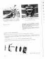
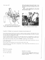
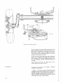
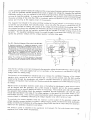
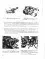
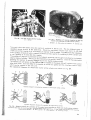
nt view of a tie-rod and oriemaiion of
of clutch cm device A “I'HOE3fA
Fig. 85. - Fro
elastic
(See the last
figurepins
for references).
Fig. a - ‘i
"pp Q
I i
A. Disengagemeni {ever adjustment nuts - 1. Elastic pins
2. Lever pivots - 3. Forks - 4. Fork adiusfing nuis.
i
l
1
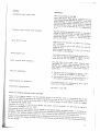
Mount ciuich on fixfure A 711063 or on fixture
A 711063_lA, remove the elastic pins (1, Fig. 84) and
Stripping of ciuirchz
i
push out the disengagement lever pivot pins (2).
By siackening the siua‘ boffs fasiening the cluich £0
fixture, a1! parts become free.
If the clevises (3) must be removed urzscrew them
from the pressure plate after slackening the adjusting
i
1
nuis (4).
l
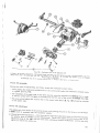
Inspection of clutch dismantled parts.
Check the oiutch components as follows. according to the data of fable at page S7:
- them;
I‘
surface smooth
brushingthem.
are
- check condition of friction linings and of metai surfaces contacting
iindnecessary
lf the rings are soaked with oii, replace them, as washing in Q0150 me a
insufficient;
-— check cléarance between the clutch driven disk hub teeth and splined shafis;
-— check the throvwout bearing, and the clutch shaft piiot bearing, located in the flywheei;
am
‘
1-La.»
~‘;';;,-“i.
%
_=,\~:" .\
w &
“.5
E
J:-,
-
1
'
\.
a
“
V-I ' » ‘
».__
._‘ 1. :._.
*3‘
54
Fig. as. - Ciuich, exploded view.
;s
1'3
VI’
ii
- check ciearance between bushes and disengagement lever pins;
- check piate spring characteristics;
- check the throw-out coiiar working siiding surface. If wear does not exceed the permissible iimiis.
the shaft can be mounted again after rotating it ‘i8G°; if necessary replace the parts when grease
I
drips due to excessive clearance.
i
‘
Assembling and adiusting the cluich.
1_;_,i;,;i¢a1§Qn_
Smear iighiiy the foiiowing oomponenis before
assembling using quaiity chassis grease:
i
i
i
*
.-.-
i
— the clutch disengagement lever pivots, the cievis
ends confaciing the disengagement fevers (3.
Fig. 34), the c1uZcn~gearb-ox and the clutch power
iaise-off
baiifever
endsends
of where
push
levers (P,shaft
Fig. splines,
88), the the
ciei/is
confaciing the disengagement collar; in addition
$
,....._.._
i_i
r
i
service the bearing housing in engine fiywneei.
\
s
1”‘
._;.._-r;»'==‘- “.F '\I
,-
1
__
\__._.....a-
'l_:_f:T
*'~i <—-_
-
' 3"
W‘
.
'
‘.__¢_
_ *"'1‘<1'”"
.._
C ’,;x_>,;y_~ < cw ._‘_ —xx vu -
M
'£-2.~¢-'=I-*- i.
l:I{'*'—‘$_“"
=—»
W
'
rams.
i,‘
155%,
W1
in .33»).C4
'f.'-~’/_,
' -
-=.:=~.‘~:—
,.
-.1
T‘
:§ F.
ii '-
.e¢;::‘=v‘" ;_=.=-~"_»1.‘=_=+e3~...'.' -, _
was
IA.- J.
1- .1
i-1.->.$'1,_
-,fi~!4.‘»§
~._
I3
'-
—..e.
-
i
_
T.\
‘_T.'.'_
‘
'
I
1
v
~
vi
. " ~ .=. 1:1.
—‘ 1:.-es.
w . .
”‘7"-“'2 1 {YT ':,- '1'e.'§-";?.-'i“-'§‘-‘§»'=_**-‘Q=~'~*-._._- II“--\.,_\
' ' .'\';=""..,=\_-‘
_.-1:?-E§~\"‘€' -‘ w
“ '- "’39::§'7;F
""<I=i_»:w,
""ror"-.=
¥;'-'_"
-"7
51;‘-Lei".-:-'='_l
P
5":
‘P’.V."
_' \
'_.;§'1.;<.-.;E;ii;i==.=i‘;
531,‘-;Tf§;f“-;7;'*_,
*___=, . _;?.'§
_ Z .-.\_\
__ -.-1-Y
» __—
. “:7 ca: -_
.
i
1
|
.':.;-..-. .,
1-‘7'?l7g":T'.‘-5-'Z:~: :;_.“ .
i
'-':=l1;"‘a.i!“;',-;
_i_;.7?‘§ ".i:_.f'_§:'-‘
.
i '
i*
X
‘ :,;jij;u;-;—\;,
.,
‘f-"1
f.}. '1'-': '§:;'-§]L;i=T%¢fifi1-j§»""
_.;_-1 -.
‘I _..v .
..
i‘
‘
I
2
4/
.
/'“mi
._, .
,1--—m-I‘--\
‘
'_T. _._._--.'
"'_.
"-"'
* ~
s__
“Fag. av. 1 Cluich section.
,
}
'
i
Assembling the ciutch components.
W ,__
'Cf.._‘\"
Fig. 83. - Clutch piaie centering with reference to points P.
it is easiiy performed by foiiowfng Figs. 86 and 8?
and caring that the ciuich-gearbox piate is centered
with
referenceastoshown
the caps
and35.
that the eiasific pins
are oriented
in Fig.
Clutch assembly £0 be performed on fixture A 711063,
using if on the side marked with the tractor number.
Ciutch adiustment.
For clutch adjustment ii is noi necessary io place
upon the fixture A 'I11i}63 the power take-off disc,
which remains outside the assernbiy, and is subsuiuted by a ring (Fig. 89) superposed to fixture E.
56
E
_
'
G
E -
D
‘
3-,, _~..
qr" ,'."/_;=
“-
. -._~» r;-y '»,;':v:
H
33
ll Q’
1,1
-r--" __
i l_I'f.';_;:"""~‘-‘Q
..
'-1:‘; ‘~"::‘I¢."-‘_E
_;.=,;l,'::-‘
\
-:5-<2;-2-~,»..=X "
~'—“*-"=‘”—'"1'<—:-W».-1 '5.-I
.-s
v__,, /____
§'='v'-'5
‘
'
“"
‘
r
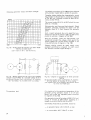
a) adjustment of the complanarily 0;’ the clutch
disengagement three lever ends. The adjustment
to
be made
the Fig.
89 :'.e.,
checking,
using
feeleraccording
gauge, that
between
thebylever
ends
and the checking elements laid upon the spacer
there is a max clearance of 0,1 mm (0.0039”);
a different clearance requires to unscrew the
fastening nut and adjusting the proper screw.
_
"]'T
_F.
;._Li-=1 -f‘.--‘
1-=__
»'.:—1‘—~>-. r Ll_,_
7:‘l'-‘7'T:‘-F
-
J
V"
‘
.1;-.§A‘;:jg,_I-"=1‘,’E;'_7‘_'T;-':.t_,__
‘-"- L‘%€:.:-l‘:‘§-‘:2£:|:§E‘£)hI-7‘ '
..=
V;-¢ "
*'=:¢-‘ K1’
-" "
*
I
I
-
.
V
_k_ _ I
¢'
v— ~
'
-
..“7:fi'_=3' ‘V
"V
,6
4'
s.
.,;:_:‘i;;5;-_;;i~":g;‘=j :1
"“'"‘-+-=~ '—---\—*""“'.'I
'.'l.'-57! '=-;.=€r'-'3-""'.irr‘"‘
-"-"fi'-‘*~*.-. -r‘-PE-.":".»:»§rv'
" =.
'_=- ?
.-
-
i
Ctutch adjustments should be made as follows:
.»§:4_A':w.».¢--s
- -“
‘~
"
w l !_‘£v__°1;i_-é,;_:.‘-_‘:‘,___H=‘=‘_-
.3‘_|.§_-¥3’k,'§j;1;::‘;‘>’-.':|?:;,:'_P
Y-:11; .~_'r1fi'i1_1==~.5.';i@»:r~
:»1~“’
7‘-
1
Mote. - lfclutch is installed on fixture A 'l1‘l063lA.
the adjustment may be made after the assembly on
the tractsr, using fixture A 117683 provided with a
suitable flange (Fig. 96).
l
1er..1F4;glhr:_'_wfl
- 7 '
~
in->
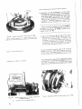
Fig. 89. - Clutch adjusiment using fixture A 711863
5,6,1»-I
Fixture cornpcnenis - D
Spacer bearing No. M1 R,
used also for other wheel types belonging to fihe series 490.
Clutch contro! adiusirneni.
Assembiy of clutch on engine.
b) Adjust the clearance (E, Fig, QB} of the power
lake~off pressure plate clevis. Check that clear-
ance be 1.5 to 2 mm (0.059'l"' to 0.0787"), and
if different, unscrew the loclmui and screw on
or unscrew the sleeve. The clearance adjustment
may also be made when the clutch is mounted
on the tractor through the gearbox side cover.
The free travel of the clutch pedal is 25 to 35 mm
M19843" to 7.37190"). Plate wear, however, decreases
fine free travel. Unscrew the pedal lie-rod clevis as
much as n€cessa1'y to reestablish the previous value.
i
l
The centering oflhe assembly on the engine flywheel
is facilitated by using fixture A 117083 (Fig. 91) that
may also be used for the disengagement levers
adjustment, when tilted with the proper plate (Fig. 90).
l
I
_
H
,.;;,_ 1.5 +.2
B“
i -~,~r-E-J:-¥l~.n
/‘\
PS5
»_~~
\_______,,_.,..----—--'
§>‘_‘{~
lg;
ll.
Fig. Bi. - Mounting clutch on engine using tool 11 ‘.1'l0fi3.
Fig. Q0. - Clutch adjustmeni on engine, using ioul
A 11'£fi63, complete.
B
56
Clearance €,5-2 mm (0.059!-0.078‘? in.).
_r"
‘
>-
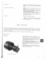
FLEXIBLE COUPLING BETWEEN CLUTCH SHAFT AND GEARBOX
Calls for the dismantling of the elastic coupling to
check the rubber block e;‘i‘7ciancy,' if blocks have
Noisy transmission.
excesslve wear, replace them.
.-_,_
I
l
.I
“ ‘~
'1’
:
I
.'.'_".-_v‘_
1~'-.1 --4
-
.
L
_
1.--=.3~-.:~‘.i~i-'_'
"“
.-}{:_'E>.\;':k;;_-'fy-__‘-
A
':'-}>?=,_-2"-‘--.*-3:
.= '-‘-
~_ --
.L|-
\\I
ina 7'
_
Z
— \ _
jg u
AW“-‘l-’“*' --
__
“ "Q;
"'-_.
/1;?
-$5
1‘.
"*':‘.>3",-'4'.E-Z"'.':'-‘J1'2.
-:~E-‘--
>:‘l§;"
'_'?.1‘: ""-‘lhw ’
,/%'%_\;f;1._‘3
. QT‘ \ \"-7
H11
‘._.
II;
..~..
'1 ~’3‘:':E';'.€'
1
\‘
1':-fill-5.‘-I
5-J-'1.-'I‘.=‘---,
V’ ....-. ~....,,_.,.---~-K.’ Q3
-'T
2
"III
\. mun \n1~*_$\_“-“\ __ 1Q \\
"'
I
,
-:- ..-T -_~ .= n_._-: .*‘
Riff
_
the fastening bolts of {he flanges to a torque of
2,5 kgm (18 ff./la).
:_-»
..,.“\
~:»-_-.~z='_: ‘
~_—
rm3:*
._‘,-¥=,_¢~_§.
.,
_l1:¢ .-".1
IT
.
._ .
3.1,».-_ » ‘.J"i]:;vPfl_— .,__.
7,21 _ 1 ._ .
___.r
When reassembling ascertain the correct functioning by locating coupling and shaft splines correctly
according ihe drawing of Fig. 92, in addition iighien
I
,,,;.:.»~
,=;'.'.'.“Ti” ‘ ,_;-:\::1'.-2'-'
_.M/W
I
l
1
Fig. 52. - Diagram of flexible tolxpfing for clutch-gearbox
'
shafts.
v
I
I
“'4
H
-as
1.4
I
I -I ;
K’
'[ IIii
.2
I _=__,.>
EM
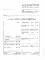
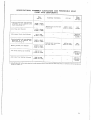
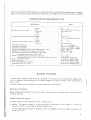
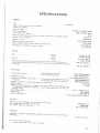
CLUTCH COMPONENTS: SPECIFICATEONS, ASSEMBLY CLEARANCES
AN D PERM1SS1BLE WEAR
'25?
I
I Em
1;
!
2'3
I §§ :
E
I cl e aran ce s
Assemby
.
In .
mm
Between wheel drive splinad shaft and its disc
0,010 to 0,105
Wear iimits
mm
E;
m,
0.0004 to 0.0042
0,35
0.6138
0.0005 to 0.0045
0,35
0.0138
-0.0809 in -0.0028
0.20
0.0079
I?
1:
I 1:3‘
1155
I
2‘?-;
..
. LIE
£2”
II }
Between powe: take-off clutch spiined shaft
and its disc . , . . . . . . . . . . . . . .
Between wheei""drive shfiaftvspline flanks and
€1exib!ejoim': collar . . . . . . . . . . . . .
Setween disengagement lever bushes and their
0,013 To 0,115
-0,024 ‘£0 -0,072
1:-»_
§._.,
11
if
I
glns . . . . . . ._ . . . . . . , . . . . . .
0,613 to 0,064
CLOUDS to l3.fiG25
0,30
0.0113
Between shaft and ciuich throw-out collar .
0,930 to 0,145
0.8912 to 0.005?
0,30
0.9118
Clutch driven disc thickness (wheel drive and
power take-off), complete whh friction fining
B,6
0.3386
T
0.2755
Tightening torque for flexibie coupling flange
nuts (Fig. 92) . . . . . . . . . . . . . . .
2.5 kgm
I
18 ft.Ib
I
Clutch spring speciiiazafions
Spring free length . . . . . . . . . . . . . . . . . . . . . . . . . . . . . 65.? mm (26024 in)
Spring {ength under check load . , . . . . . . . . , . . . . . . . . . . . 45.2 mm (£3795 in)
Check load
. . - . . . . . . . . . . . . . . . . . . . . . . 112,810 124,6 kg (248.7 to 2':'4',7 lb)
€'-\l...-J»
'
/
_
-‘w
’
_‘ in’
ll. Elva‘,
4/IL ‘ 45/"ifs.
,7 ».._’_ Léw
c..J'.:;
:1"/.
.
-4 ,
I
f
57
I
Z
-
4
1
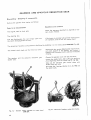
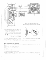
GEARBOX AND EPECYCLKC REDUCTION GEAR
I
I
Dismantling - Stripping of components.
Remove the gearbox from tractor as toilows:
Pgrts to be disassembled.
The engine, with its from axle.
Operations and cautions.
Follow the sequence described on page 53 for the
main clutch removal.
The steering box.
The two foot-boards, the rear temps cable and
the dutch disengagement tie-rods.
if the tractor is provided with oil lines rfiihning from
the hydraufic pump to the lift, remove them.
I
5
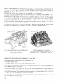
The stripping of gearbox components is ’§aci§itaied by instaiiing it on the rotary stand ARR 2284 (Fig. 93).
The centrai clutch shaft and the throw-out collar.
Remove the two screws fastening the clutch throwout collar .5UppOI"i to the gearbox, and remove it
together with the engine clutch shaft and the fie-xI'bie
coupling.
The gearbox and the epicyciic reduction gear
shifter rods.
r
Remove the gearbox cover with the shift lever;
remove the shifter forks, after puliing the fastening
pins, beginning from the central rod (2, Fig. 95);
siide out the reduction gear control sleeve with
shifter forks and rods;
take away the 3 springs {Section C-C, fig. 108) and
the detent balls.
"-.:—--.
1
I
I
I
I
I
\
I.
1
'./-'~ I
";;£
__
4. ,
Q"/ZS
:\‘\
- _.
" 3'?‘";’
=i»a
o...-..
t'*i'?" 51? - *:,..T1‘," “L; g; .
- .. 1. .I"-"**¢"-‘.'_'<f"""",“9"" .41; ;__;,;1.
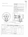
Fig. 93. - Gearbox casing mounted an rotary stand
ARR 2204.
58
Fi . Q4. - Removal of gearbox casing from tractor.
Q
i
E
£1
l
lv
Fig. 95. - Upper view of gearbox control gears and shifter
forks.
1. Shifter forks for 1st, 4th gears and reverse - 2. Epicyclic
reduction gear control fork - 3. Shili fork controlling 2nd and
5th, 3rd and Sih gears.
ll
Fig. 96. - Disassembly of primary shaft.
(Arrows show the wooden wedge and lhe punch).
Note. - When also {he secondary shaft is to be
disassembled, engage lwo gears in order to unscrew
the fronf end fasrfening nut.
Primary shalt.
Take away the primary shaft front cover and remove
the shafé by hammering on rear end.
Prevenl the rear bearing from coming off together
with the shaft by placing a w0oo’en wedge as shown
in Fig. 98.
lf necessary pull out the hearing also using punch
A 9613703.
Reverse gear and its shaft.
Remove the slop and slide out the shaft together
wifh ihe gear.
Should fhe shall‘ removal offer some dlfiiculty, apply
a screw to the threaded hole in the axle.
Remove bush from gear using the punch A 928251.
Secondary shaft.
-04-.
Remove ihe epicycllc reducllon unit and fhe gearbox
wall lnner thrust disc;
slide out the secondary shafl with a bronze punch
hammering ll on its front end.
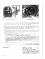
Checking the stripped out components of the gearbox and epicyclic reduction gear.
Check gearbox and eplcycllc reduction gear components against specifications of page 63.
Neither gear teeth nor chamfered surfaces should he damaged.
Check if the teeth of mating gears are working on the whole face length, and if the surfaces are smooth
and free from signs of scoring or hammering.
The sliding gear hub internal splines should be free from marks 0% wear or seizing, and ali splines should
have their corners without signs of hammering.
The splined primary shaft should be absolutely free from pitting or scoring. especially on gear sliding surfaces. Slide the gears on the shaft and check for clearance between the gear guide flanks and the corresponding shaft spline flanks.
59
»
I
F .&f:A§;?¢‘I.“
‘I
_
_-
~': '1
I-_T‘V‘V
lb’?
E
1 =:~
_»
_
lllli
llllll
mm
@£1
%M
—- - -""
:_.'"""
I
<-__._.___
'
‘
_
r
E
‘gal
,i
_ <,_
.
.-
,: wt
r.
'@
\ /
@\
we ‘B
@
€*_.T. '3?l
f
Q
Fig. 9'1. - Gearbox and epicyciic reduction gear parts.
1. Clutch~ge-arbox coupling - 2. Cover gasket - 3. Primafy shaft from
bearing - 4. 1st speed and 4th speed gear ~ S. 2nd and 5th, 3rd and 5th
speed gears ~ 6. Primary shaft rear bearing - 7. Reverse gear mounted
on its shaft - B. Secondary shaft bearing retainer ring - Q. Secondary
shat? front bearing - 19. 1st and 4th speed driven gear - 1?. Srd and
6th speed and reverse driven gear - 12. 2nd and 5th speed driven gear 13. Secondary she'll rear bearing - 14. Thrust ring -15. Epicyclic reduclion fixed gear - 16. Thrust outer plate - 17. Epicyciic reduction driven
gears -18. Shim rings -19. Reduction gear engagement sleeve- 20. Driver.
gear shims - 21. Stop ring for pivots - 22. Driven gear axle rollers.
Note: Starting from chassis No. #27935 helical teeth have been super-
1
g ' gt
\
62
I7‘
'~
Q
1
‘“"
20
®/
'-ff
1
‘Q
...;._;,;
§i:.,_W.;;..,c%-:
ir 5;=e?;i;"~:
‘l
J
l
l
__
e__
j
i
seded by straight teeth.
The reverse shaft should be smooth and without scoring; it the permissible clearance between the hush
titted on the gear and its shaft is in excess of the wear limits, replace both bush and shah.
The bail bearings should be perfectly smooth in operation, without clatter. The epicyclical reduction
driven gears roller bearings and those for the bevel pinion shaft should have an assembly clearance not
exceeding the value listed at page 63 and the surfaces mating such components should not be damaged
in any way.
The gear control forks should be checked for deformation and hardening characteristics of the working
surfaces. They should slide freely with shifter rods in the box guide holes.
Replace gaskets whenever worn or damaged.
The epicyclicai reduction gear thrust rings should be checked and it presenting signs of wear should be
replaced.
At gearbox major overhaul, remove the control lever sector plate, located under the cover (Fig. 98), in
order to check its components efficiency, especially the ratchet (3) and the control lever dowels £1},
which are subject to wear.
.<_j ‘»‘~_
'=‘}'1“‘“
‘sq,
1-.
_., .
,__._ .,,‘;.,,.-_'
i, —_-.:_=...-;-;.;~'1F'~*--""“
"~_
'
l5:'f-.i’.'¢~.=."I"
' .
1-i.-re:"‘$ '-
—~‘ ‘A
-‘:2 ,.
>1 = ..
I
‘l
‘/-§.f‘“‘—‘L'1'!5§->‘!7*7T\'3’
- J»,
_
jg
,_
_;::_-, ,'-',,_;_i,1.-.'-'.<¢f=‘-.1’ “.1-2*
. . 1,~;._,;= ' - 1...-:1
lg,
»‘.;~;- '%:*:
_r;J;.'
§z_;:~§/: ,_~.>.1 W - -?;;,.=—
. ;.-‘Y. .f"f
.
.< =~ v_=.-.1‘.
‘;i:,M<.;."_--
€
"W -‘-.§1ifiF1:'=.‘:'.7i 1'-.
'Ji~'-"~=“:.--'.:'§=""_'=_.‘u, "
_;;~,.=:_..<:".s~ -..-‘ l:
‘—
's._“r;,.;-,.‘%~_...._,.'-r."{';'_.~';.»; ,
-._.=_ -‘gl;—,‘;"-_f—f . L - - -1 _. ."i.\l':'v~;-?"".‘;':':'L'}‘ .
~''3?
-T-ivf’
5
..
6»; " ‘*"»._~%_e;j;_e-;-‘-Id.*¢*=.~.~':I-21
.-if5‘
,
‘§:‘r.;:.-'=,3“;.;-3;.
»~3_:
1;3,-1.';:’:u'=,="i'.
E\E_§§_
;-...=_,~."'
i=~= _ I i 1--K-_=~‘e_.~~
7-2;‘:
='""-"."-- 1- ’
1»;-:.'.
:' 1 u..~
:53.
.<-4 ~ i¢;;_,.<. -_.
..»_.‘_-_V_e.~,_;,
..,;_.\~
j.~.__..-"__ _
-133.
_-_'§_ '7"—" <l‘j 1"-1?‘
1
2
r‘.'é.."§‘
.i,~.-.:~
.. 3- ‘
.-. ,.,
_ *'
i
~-;'.'.="'
"A :'¢.=-'~§--:1.;.;.5-'
wk
fucjw. M.’/'_.j_;_::-;;___:_‘-,:‘J._N."..
-.1?.»?%zLh-1' -".5" _,,,,.";‘-7"lz,r'~*. - "-.5
e. _
ea
;_':¢,i<;;,*:_-‘,Y_/.-I
l.
- -
'
<
.'£._v.l-‘V’,-,'.» *-
‘."-’$T~=i' 5'
-;.-':"i':>*'i5
11¢”-5';:o';--_-=.§¢""'""' '
~.-,“.-Rm_.- R»-~. ,-.
Fig. 93. - Gear shift lever.
Fig. 99. - Assembling
epicyclicshaft.
reducfion gear on
gearbox ofsecondary
1. Control lever doweis - 2. Sector plate fastening screws 3. Gear selector pivot ratchet.
6. Primary shaft rear bearing - 14. Shim _ R = Reverse Bea,shaft » V = Shim pin,
60
il
Gearbox and eplcychc reduchon gear reassembly.
To reassembfe geaubox components proceed as roiiowsz
Paris to be assembled
Operations and cautions.
S-=cond=ry shaft
Assembfe on the shaft the rear ball bearing after
heating ii in an oil bath to a lernperature 01‘ 80° C.
&ppr0X.,'
install in éhe gearbox fhe front bearing after sfiding
in the shaft from the box rear end, and mount on
it the gears according to Fig. 97.
Note. — The shaft nut tightening sjmuid 59
made after the insfaliafic-n of the primary shaff, as
if could be facilitated by meshing two gears af the
same time.
If the bush has been replaced, after reassembfy it
must be reamed using reamer U 8321, up to the
dimension of page 53.
Fasfen fire reverse shaft (R) as shown in 1~'ig.9B.
,_ - - fiW_____.__.__
5
II
\
\\!'».:,;)€
I18
\§
"~§~=¢
\\
\‘~<aq
‘On
_\_
(§1:
\
say
1' W{I
\.‘\
'U._~
W’
was
muj
:4
_nT
¢*ii;.
x//
‘\-=—
a
19659!
.L»f'~'., ¢ypg _
_
3‘ ~ _
_ ______ _
'°'
_
'/
I
2%?.. F‘?'-1%..
ti ~ —
-
____ ?
Q
fifi“ “
I
~ H.»
‘$1 *
'2-,_
__
‘
$3?!‘ 1%;
"m:."%'".;.§“**“ '
;>
'"
______
mu
_
————7——
—
3*‘?
_
gggfi
Ea_§“________
~
"—'>
v
§'§°§“..'.1:-.,.,.»~mw
film
,
11-.|.m-'-’’ “5‘" ‘ ?4%b_~.n.\:'k|
II
filnv
_,,
—-
_(.—
A A
\
I
"%.~/
‘
_
L
_
*=—"‘
q
|
\
n F ‘_
\,
‘
\_
r
I
t
\
\ 9,9,,
{gs
"<
__ _
‘\
I
{\
fig?”-1,’
:&1
,
1
/
ran \.
:;t
‘*
\
_;'
7 7
"-* ‘M‘ " '
Far"
'a
_
7
_
"“*_
'
' ,,
1 =
~uBs2r~
§.aw¢ =m-oz-n», :-~=v.,:>_§_
‘Q
‘* ¥;~'§e
*2
5),,
§i‘
QM
ll.
‘
/,__,_'
_
’
».-.=
‘Inn. if .141-'
> ,_
i
‘-:9-W
,'* 52%“.
""""
'%%>»~=<~
'
l|uILl;§;§;. __ _ _ - ‘ "" ” ‘* F?,,_W___-___!
1
4."‘
<aa's
R
»-;_
--
rm-V‘
--
_, .' W “““
V EL 1n E ‘““ "
,:_
_
4pm»---_:~
\
_;--E
g
.:’"‘ "1
.
av)“. V
§___
,’,;$/I .
P‘
\
\\\\$
i
, )
7‘
an K
'
.
‘ , ‘
"14; -E.*i=£| F)?’
Q9 \\
--
:
\
_
‘I
I
\.
"I
2
\,§\x \\
‘~'\‘-\~_\' 2 '
,,
~-
-'
w
-_
-\
Fag 163
-\
Gearbox section.
1!-21’-31 I-2 3 a e |ndxcat|ng respectively ‘ls’: End, 3rd 4th 5th and Bth speed, obtained by the displacement of the epicycfic
§'%dLECtiUfl gear sieeve according to the a row lZ!H'ECfiOi"l indicated by r or opposite tn 5:,
Ra Taper ro¥l r bearmg adjustment shims
Rb
Rmg for centering the pinion on bevel ring gear ~ Section C-C ihmugh
CGSIFQ fflrward wail, ar'd correspondmg to tne control rod - As Rod - Sf. Balls - Mm Bali sprin 95 ~ b. R eve r se gear sechon.
'
61
i
A .
—~-
--';-:3,“*7
h;v='..1=-'1'?»
;
fie‘-<;;i=I<'" . 'I>- ‘r-.
-=--Y, ~~.:;-_ \.
.
.
.. ,
~Q
m___._=..:..-:.-..‘.._-....._-.....T_
..__'-_.
_ K. -..-5
"
Y
1-
;
‘I-..‘f_#::: Q5
*
J ‘*-.635" “" *""‘*‘-"‘"'“-
.
3:‘
4
1.
1
"h:~ll'-‘-,1‘
:21
'5
L..,»,!'
T.
-.
-
-
."';
:‘;~';u.5<‘.,1?1"'»_€";--
"ii" I"
l;§'~‘,
L
l
*
$2-{ "1 ==
-Q3‘.
Y
»":.P;=-‘re '
1
=
l
/I,»
>".=»-.;<\;+;",*\ 5*},-1;
.
:
1»
Y
-
<
'
-.1-~ . . .
.. .;"..'-:1.-.. -.=~
Tel
- '
'1.
.
its
7 2
Z fl;
:.;.-:'~'»3 .\ -:3
ea -A.5-‘i"ii“'»j:I.:. =I=
' §—w-,;:;
‘-I~='
J
Fig. ‘E01. - Epicyciic reductiun components.
(Note: Skirting from chassis No. 427935 up helical teeth have been superseded by straight teeth).
.2
Assemble the epicyclic reduction gear c0m,00fl8niS
according to Fig. 101.
Mount on the gearbox the primary shafi rear bearing
Epfcyciical reduction gear (Fig. 191}.
{6} and fasten by its pin (V), the inner thrust disc
(14), having its lubrication passages Iocéied as in
Fig. 99.
Mount on shaff front end the bearing, the oil baffle
and the efasiic rings;
slide-in the shafi from the case front side and fit
on it the first, second and third speed gears;
Primary shaft.
-
_
~
<~
-
—
__
I+ ,
1
~
_ " ; .'5.
'
~-T
-
»:- >'
I
__
<,.-
~.:'-@;?fi..
. -‘ '_ .
.
.;?‘~.
~
3.
1.
2
.-
-
-;
_
-
f;-¢.Y ~=:—- _,_ _
F
- 5:
.
.
.
W
1
and their gaskeis.
When mounting the first cover, slide if on fixture
A 137003 which avoids the oil sea! gasket being
damaged by the primary shaft splines Confacf
(Fig. 102).
";».-:5s'_i-.415
.- r--334"’
'-=-=1
.r@F'f.--,-__
.‘I
., —
.
._",,.=.~.._.?,=::;;;=~
L_-
- ~_,.‘.-Y.
P "~:*-=~-.~.~::u='=“r~J“-'*~~ .
.~f"?.E
mount the primary and secondary shafts front Covers
'*@='-‘~i=‘:‘~ -a:_;'¢:.-r,=fs~’1-1:-.'-
A '
'~~‘--
,
';,<+i=;_1;-/,€;;i5;.*.<1:.5.:
1’ —,7=f5":§:c'
:‘#:1<2-:$-
'"1%¢:'{‘1i‘.2-"A,
‘
<-Y :1"
-"
. ~'-"..,. Q-.~¢>.11&?~:,-$1.
1‘;
‘-
- -~=.;_~;= ‘;.==:-:-
%»‘=1"<-14;'<;:;':=*-\\‘-5:1 .,1-»¢<,,
. ..:->’_:\.*~é\'.. -'1 '- "= .‘A _.
‘ .r
;:‘*""'
5‘?-£i~‘='. '="
- .'+"i:I>.‘%="
.- -'1": 1
_
~ n
‘;,.;~._- 2' ii.-.
‘
(;1':‘;I:_'::"-';~€:;£4l;..
,, . . ,_.,, ..
.
,$~‘.'we_;§",»\_-;g.g.-‘¢,-=-
?=-=-»'~e1=;»'-'=.
&,;'»'-,:a;N-~.~
.
->,!\;.
:.
"'= '~
*
"
.
" “"~~"~'1='i=-;
--~ =:*.-s~1- gag. 4. ‘*+=-@:='11..-,
.¢,=',-_ .__;._
».~~ ‘_>1.~.:.~-9,59;-.,»..-1:2-»:.
;¢;,;;;-|‘;~.¢,-’_~=;.\-.,_-=;.'==->~Z3I;="
__.;,; -
es
1
. ye
14
;--
'
E? -‘2:1"l?<5IZ-fl‘/‘»Z!1':
.
»..;.»-' .
.-
._ . I
-
'
.
..-_i ~ .- .~- - '
'"~_
'
—
-_
—;-.
~. -.1i=~,
:29-,1"'
-'
»~
. ‘
;
*
11
1:
11
#1.? "~.'1'-."—¢‘-lo,‘
.
=.4¥¢:.i.:".'-‘:*'!!:v9=@@$§=_=,-4-1.1?-.1-i~11'?:%=£a§§!='=>
.
F.'-L';i#'*’-'—'QL'_
E»
iv-.‘-.4~1~ -
‘ .-.1‘ (~".L
:-
$5;.e1-,;;._.-‘J:
§_;¢;;_:,:_1.;i
-'
1.1,. e?‘ .'.w..~ -’*
.- »"‘-.. ‘ fr
e '11:“-=;>'
‘
’i
"' 9' {:-
Rods and forks for the gear contra! (Fig. 95).
Fig. 102. - Mounting ihe primary shaft front cover using
too? A 137803.
Introduce through the gearbox wall holes the three
detenf springs and mount the ball and the first
gear shifter rod with its spacer and fork;
introduce through the waif middfe no/e ihe two
epfcyciic reduction gear control roe‘ check belfs (see
é_
{_X
F
diagram C-C, Fig. 106) and compleie the assembfy by
infroducing {he two balls from the reievamf hole and
rnoum.‘ ihe rod, ine spacer and fork aciuaiing the
second and the third gears.
Fig. ‘I63. - Orientafion of the various spring pin cuts with
reference io direction of force (F) or of rotation.
Note. - The cuts of the p:'ns fastening forks io
rods should be oriented so thaf the strain expand ihe
pins in their holes (Fig. 183).
Gearbox cover with control lever (Fig. 93}.
Mount the lever and the two dowels in the cover
and add the cap and snap ring;
\x
62
I
mount to fhe co-/er lower section the sector pia-fie and
fasten it wiih the two screws (2, Fig. 93); mount
also the gear selector pivot (3).
Before mounting ihe cover, shift in neufrai all gears.
Mount on gearbox-clutch contra! shaft, the flexible
joint, the suppcri, the bearing, and its disengagement
Gearbox-ctufich control shaft.
s/eeve.
Before mounting all parts on the primary shaft, be
sure that the sea! ring is 1'nsz‘afied (Fig, 97),
NOTE: Shift the gear shift fever backwards, thus disengaging the reduction gear, in order to faciiitate
the operation of fastening the gearbox to the transmission casing.
GEARBOX AND EPKCYCUCAL REDUUHON GEAR COMPONENTS:
SPEGFICATIONS, ASSEMBLY CLEARANCES AND PERMESIBLE WEAR
Bat?
mm (In)
‘
_
,
Assembly ciaaranhes
T
'
0,35
(03133)
Beiween gearbox driving w
0,10 to 0,20
3 and driven gear toath flanks , (Q0039 to 0.0079)
0,50
(O-.0197)
1 of epicyclicai fixad redu<:: tion gear
Epicyciical
reduction
driven
gear ;
j Epyciclicaf reduction
need,“ éiamaiel.
driven
gear
needie seat diameter
1
,
20,41to20,¢3
limits
mm (in)
Between gearbox shaft ‘
0,010 to 0,105
splines and their driving - {Q0004 to 0.0042)
and driven gears
,
i Between driver: gear pinion .
‘ tooth flanks and the flanks _
1
Wear
mm (In)
0.07 to 0,13
_
2
(Q0028 to 0.0051) ’
j
W
0,35
(Q9135)
‘
E
,
§ 10.5035 to 0.8043) Y
‘“
,
0,01 m one
\
2
2.99 10 3-9°
1 8e‘W?en ‘?°“°HB$ an?‘ axie?’ 5 (M004 to 0,0024) ’
_ (91177 to 93131)
of eprcychcai reductlun dr|'
E-Ipicyciicai reduction driven gears axis
diameter
Q
or
(0.0'0§9)
ven gearS
14,-$00 to 14,389 I
(05669 to 0.5665) _
I
Reverse shaft bush inner diameier
25,065 to 25,098
{obtained by accurate tapping)
5 (£19868 to 0-9881)
=
WV ""”""W WW Z" 1""
Reverse shaft diameter
_
7_
gr 7”"
=
- Between bush inner diam- 1;
777‘
25,000 to 24.979
Bier 9-fld H5 F9‘/9l'$9 5115“
E
1 (09842 to 0.921.243 ;
I
!
0,065 to 0,119
(919925 £0 Q0947)
_____ ___ ___
, _
.
_.
0,30
,
(Q0118)
'
V
'__
_
:
____"
i
5
g
Control rods release spring
Spring free Iength _ _ , , , _ , , _ _ _ 36,5 mm (14370 in)
Spring length under check load
Check iuad
1
Gearbox seieciion release springs
1
. . . . . . . . .
21,2 mm (0.8-345 in)
. . . . 31,5 mm (1.24CI2in] , Spring length under check Toad . . .
‘
16,5 mm (£16495 in)
. . . . . . . . . 14,710 15,3 kg {32,4 to 35.9 Ib)
Spring free length
Check load
_ . . . ‘ . . .
{SA to 20,4 kg [40,6 to 45 lb)
n
,
1
63
4-=*N.¢-,~v?.HM- ,w._i
BiFFERENT!AL
AND
LGCK
The rear half of the tractor body is a case housing the differential assembly and its lock; it is closed
at the rear by a cover through which the power take-off shaft projects; the belt pulley unit may be attached
There/:0.
The case upper opening allows the fitting and removal of the power take-ofi drive and driven gears.
-k
5'!-N-',a1'.'*=‘=-"""“""“""“"' ‘
_
Fig. 104. - Removal of engine and gearbox from rear
Fig. 105. - Transmission casing rear cover removal.
transmission casing.
Disassembly.
To remove the differential case from tractor and to dismantle it, proceed as follows:
Paris to be removed.
Operations and cautions.
The hydraulic lift.
Remove, if installed, ihe /lfl unit, its oil lines, and
the implement hitch.
Drain lubrication oil.
Remove the two plugs found under the tractor body.
The gearbox from the dii-Ierential case (Fig. 10¢}.
Disconnect the rear light cable connection.
Place the differential casing on a stand and lift the
gearbox with a winch; remove bolts connecting such
two components and disconnect them by a lever.
l
l
The final drives (Fig. 195).
Remoi/e the rear wheels and their discs.
To help the disassembly ofthe various units, remove
the mudguarcls.
The soar.
The seat should be removed lo facilitate the operations which follow.
The transmission case rear cover (Fig. 165).
Remove the dlfierenlial case upper cover and sei
the power fake-off control levers at the position
<< MOTORE n (engine).
Unscrew the rear cover fastening screws and remove
the cover by pulling and lowering it very slowly, {'0
allow the removal of the front bearing of the power
take-off shaft from its housing.
l
64
l
l
At the same time, remove from the upper opening the
\V
./‘w
."
r
_.*'
- Y‘
/'
. J ~
.
gear which is thus free from the shaft’ end, to avoid
damages from its faffing in the box,
"1
T \
'
1
-
1,‘
.
‘-
.
.
‘
‘
-
Note. - To easify disengage the rear cover from
the transmission casing, set the power take-Off
engagement fever in the <1/VIOTORE» (engine)
posiiion.
,
‘ ,‘
,
1
<*rW?;
‘?:§=,i" %ifi*§%““e
;.
I Y -T-; y
Q: _=‘_
5%"
1
Wlf;--‘ »
fit ‘-.
;-5 t‘3§;I&}
5'
if: f-="1';‘f
V
‘ha, _-A
.V':..,_.~
. -" T311 ‘-.-.1-‘ -' _7
-L, -J - .'_';.;; _ ~_ -.
'
wYmfl
Fig. 106. - Transmission casing mounied on rotary stand
ARR 2204.
The differential iock controi.
To inspect or rep/ace parts remove the rear cover,
ihe pedai compiete of aiiachmeni, the plug from the
shafi /eff end, in order to make ii possibfe hammering it out from fhe right side.
Differential gear Casing supports.
Fasfen the casing on support ARR 222$, mounieo‘
‘J97
3
-.--\‘
Y
on rotary stand ARR 2204 (Fig. 106).
Remove {he gear casing supports and remove the
bevel gear, complete.
MNWWWEYMM
'l. :;1"
L‘).
,___/-f“
if ihe difiereniiai casing inner bearing races have to
be removed, use puller A 537105.
_.7_\_‘- .__¢,-y.
\_'I~
I}
<_-5.; ,
~.~~;-1“
=
\=:c-==\=\y;zi
L}, ‘. z*-*-' ~*
|
1
31‘!!!Llsih Q .
s'fi§§W@it
.¢.
>
—,
.1_ Q V
‘__;;._¢:>k~_*__—:;‘iii-_:r?;1i;;;;;:';;~$_‘
*'
_\Y'§Z'.§s,¢j§l_
~..~
K. 1*, \c_ 2 1u>»'~%:;i-§:= ,es~:'
I
gs,
..r~¢-.
.\
= . P ’ ..»~—v
A‘
.‘-
-:u—I4
F.
»_;.
‘§»."-‘ii; <51: “
_o
:
=..
\‘
- =
F~¢*fl;fi“F€'fiQ*
,5
,- it-1;;
1':’f':_"-“
’. Q . ;-.~“";r;-t-,1
,, J"’”’f‘
V )3?
1
I
i\
\
Fig. 167. - Lock conirol spring mounting using tool
Fig. 108. - Beve! ring gear assembly with differeniiai.
A 237033.
1. Differential lock.
i
(OFI WP. the spring is represented before assembiy (A) and
after assernbiy (B) on the tool).
I‘
I
65
i
|.
4
1:
1;
‘_
‘l
'-
‘WE-s
-
'4.» 1’/®
a
“T4
'
-
6
C0
)
e
"
i
Fig. $59. - Rear iransmission components.
1. Differential loci. - 2. Power take-off driving gear - Ra. Bevel pinion roller-bearing adjustment shims - Rb. Ring for centering
bevel pinion on ring gear ~ Re, Ring gear adjustment shims.
The bevel pinion.
Unscrew the beve! pinion shaft fastening nut using
wrenches A 711109 and A 611108 and stopping
the rotation with the brass hammer A B61322.
Remove the shaft by applying a bronze punch upon
ifs front end, and hammer it out.
The power £ake~ofi' driven gear and the spacer are
removed from the casing upper opening after setting
ihe power taI<e»off engagement lever in the position
marked << CAMBIO » (gearbox).
inspection of the stripped components of the differential casing and differential lock.
.
ll
,
5
i
lI
l
Accurately clean all stripped out components and check if the gear meshing surfaces are in good conclitionsi
»— check the diiferentiai gear thrust rings, and the pinion bushes and thrust bearings vs. ihe wear limits
oi page 59. When replacing bushes, after assembly, ream with expanding blade {earner U 6‘lf814
to achieve the prescribed clearance;
-— check the copper lining on crown wheel hubs. and replace such parts if the coating is not sufficient;
- check the taper roller bearing and the differential axles oil seals;
— check the difierenfial lock collar working suriace and the pin fastening. Check the differential lock
control spring (Fig. 107) by a comparison of its characteristics with {he specifications on page 69.
D iffereniial casing asse mbiy.
See Figs.1H9 and 118 and in addition bear in mind ihatz
- the planetary casing is secured to the be-vei gear by bolts fastened to a torque of 4.5 to 5 kgm (32 to
36 it.lb);
—~ the differential. pinion axle is held in place by two special head bolts, the same which secure the
casing is the bevel ring gear;
66
l
l
,l
~>l
l_
“‘SL154’
_~>
l
\
‘r
s l~
A
. _.,-)
is
./W_/5";
'\ '* K
,
,_Q>\
F‘-1
_“'~.“
\
\, L...
_ _ _‘_~'¢:»,‘\El;
R
‘Ear.
'1
~
V - : 4
'
\.“' u-
_
2
-
l
r,
ii
./‘T
'
\
Q
"i_@"l@‘-i=- .---
_-
;
it
IT *‘ ' 5
'
_
Q gr»
" ‘
'
_
. z__r_';»\'i*.*‘_iv€fil-if _._
'
_
l l_, 4, i
-*‘
5
_|_
.e,§
én
, W
“~-
$’*%-s
_u'
ms
V H 4*f§::-as
no
l___ I 7”’
-_
J‘
i
w->3 1
6
.
W‘,
' _ ‘:-5
3>
é
._./
.; I:
ls.-.;
.
‘ii
lg l
~»u;,3,g5;_ .M.-&._-1,
7 f 1%
l
1‘
ii
i
Il l l
W4'
/
~
114%
15%
:21.
-i"'»#._l-I
9_~
_ l ,
‘F
_k_
‘l > .—— s
.'_
~
li"“fl
,.i,.;T,,.,*T-"
isig4:
1iwi 2,-s»
-"“—"“‘"""
cu
/'
\x-..\-LW.._._.\-._~._. . _ .
M5J..A:<
A-UMZIW.YI£A\F4 PI'\I§1'Ii"NT-V." \./K
,.,,~.\’<{.-:. 't:*>»,_‘.1
,
i
1
V
Tl
H
.:i _W, 'hilfii
A
§
i
i
fl
= w --*='-""*'=*-*’*‘¥‘“‘~*‘*'~ - ,
'
1
_
‘I
*L“'.v;
, *
I i
_
-_
r1-“*3
;:.;_;_ \">
.s
ii-,=g,“
1*-=1-l K-\ .
#_
/_‘
\
'\;
0
'
,(-
;
a
;s€
:§?.33
2;’¢1;2'2'~"n
/’>‘_},'; ~
36%m"_-‘Aa37
/5?"
gi~!"’
-i"‘ZIn
‘»*o'+“’
l
“$
.
», -.
§
‘xx
.
‘Jem’
art
'9-r
¢*".‘
i
"
'
£74{fl
Fig. 1113. - Rear transmission sectional view.
1...’?av‘
R: 7 Ring gear shaft adjusirnent shims - a = Drive wheel
shaft and spacer, up io iracior no. 4-33¢S5§.
F’
/
L.2z'&,e_
\\
\;\
\.
M».., ». ,T;4_
— the assembly of the taper roller bearing inner
*
races on the casing should be made after
-._>.i4_=. .
heating the bearings in an oil bath ‘co a temperature of 80° to 90° C; the same procedure
applies to two bearings and to the power takeoff driving gear, on the bevel pinion shait (2,
5
_;
\ ‘\.
\
\ ""
To facilitate the reassembling of the differential
I
l
%/
—.¢_¢,_;;;:: ;.
’ ‘E.
'\
"
"~:»:~ .
\
Fig. 109);
~— the differential lock control spring is installed
as shown by the Fig.10'I, using tool A 23"i'lI}33.
sr
L)‘
1
Fig. ‘E11. - Bevel pinion and gear correct tooth hearing.
case to the gearbox, we suggest placing very near
to the shaft {Font ends -— by manoeuvering the
relevant levers —— ihe power ts5<e~0fi driven gear and the reduction gear engagement sieeve.
|
I
l
Bevel pinion and ring gear adiustmeni.
When chécking or replacing the bevel pinion and gear, the following adjustmeni sequence should be iol~
lowed:
a) bevel pinion shaft bearing adiuslment;
1
b) differential case bearing adjustment;
‘
c) tooth bearing adjustment;
cl} tooth backlash adjustment.
l
The sequence of operations is as follows:
al lr:-stall the bevel pinion shaft and its bearing, the power take-off driving gear, the spacer and the
adjustment shims Ra (Fig. 106}. To calculate the shim thickness, subtract from 58,5 to 59,5 mm
B7
ll
F-
i
i
i
i
. - M,._ _. M_. ‘_,. -
\
,i'-'.
' =-'s=.-
‘
_I"‘
‘L-"=
1
=1
::A-‘:11,-,‘,*~t;=-4-="=-V
- 1==::="; "
.'fl.'lz‘,_1q-“=:;l‘{;‘r':;":v,§T11?‘
-. _h_
'». *=“»;~-:-
=="ik1‘-f<?‘.-T'-ii"
.
*
t-.
'
4*
;i-
I-";“i“;1'-‘<1.
;:-;'1,+:5;.t~;"-1
; kt
=.=f;: ;
-
_-
5n$"l€l~'!“;
fl‘-'
i
l=“‘-Q
'
1
T':‘<.?i‘l-1'
it
fa.-'1?
5;?-i=_‘.<~_31,
_i
t
‘_
-
_, ' ‘.1 .-
ii~‘l'-'1-‘¥.§-.-.‘
4;_$"“_'».",3—-'~
,-i if:
"‘ "'-P?‘ - his
;
-.e">‘”*§e~;;2§-1-;-$11-?>,,=,_; ._.-..‘..-.
-- .
‘L.'1
‘
21~-W =.- -11-‘
-
=
._
V 2*?
' ~4*
"' be
57;
~
rt
t '
‘¢-1'-1 '1'.‘-’=‘;":?..i. ,"-'%':1~-L‘-'»
:-*=!~. '
_» ..
_.‘,‘:<»‘.:It.l= .\
iL:
. t
/r
»_=- 55"
< i =-.7-:10-.=< -
r-1,51“
~—. irr;_~
".-.J~.*- . -.-',~"_'.;_=u:-1-=,;_.
'---*6 =~»‘;.-2-is '.
"1?-mi"-T;'-,
--’75'-v="»-1.
1
.1» aw
“'1-‘»-J:-“i 7 .1!
-vi.-Y
1 1 ' FIT?" " " cl
_ is
?'=.
*
=1
.i
.
-~‘-1::;%;,'-‘.i.E'g.- _‘= ti '-.5 5.‘;-tile‘
'-'11‘-"1r:n=s:; ‘~ 1
er
-
“-7
Q“
‘~€1.'-i ;-.‘."*'‘.-1"'5"’
=
- "
1 1.‘-=1‘-:~‘.>:-'
;,‘_ - 7.x‘;
:-"=,_- ,1-t~_
._+
--:=_ -,3--- éf:-}L_‘f‘|-:13" t,.;
1»; ;
rir. 5»-'=.-4Q‘-. i"':’.'§1."
‘
f.
I-I‘ ‘Se, . :-; -<1-1»t:t'.*+
>"~
i
2.’:
§~_
==' 11*‘-_='z'<-i rs;"*
=
¢ f-‘-14¢‘:,t:.=“i"i:¥'1'=<>;!"l"': :17‘-=",'-*,';‘:=='».=!?E3t
_ ~;' E" '.-'£,‘=fi?2i';‘;l-Fh\;.? :1‘ =
_4J';-P1
V*_':~;‘;V‘:"V;"r-l ll?‘ ‘E1
=»'-3"F;‘—j"-L‘.-‘1 ‘.1,@r'>c::.'s.¥2:;<;.?,-. "-2.11.153‘},-s-,:T-,-,'3;:--t=1¢l'iS;==‘4'§'L;H;e¥_' I"g‘{,-i:;‘3'5_¢-'-i.;r_ -
~
"J, ‘ =?.'-".=‘:1"f"i",J5:=,..?—I':"§-is"'eT11‘='*~i.?;if"
=.-= -~-.-.,-_,.- -s
+-set» ‘
,,
*':':e:3»' '."‘I
'
V-¢e<1-=_ , 1-'6;
: 7 l‘ ' '- -3'55?
>.:‘=f';a-‘*5?-til?-'¢$'."*1" -1‘ ' l . ,
"11-’-
=;¢:~
,‘ ~ ;~€-
-
f£1?'_=‘=5"£-:;“fL§fi.?1‘!-iii’ 7v“l-%"£~’*;’3,-i=1‘-;=='-1': -.i‘3i.l";i.‘lY;l'j*
l.
9’We
@,
zif;
"~
1;: ' kl 5.-ihjri
K: - ~ * -1'fli=-*l"I‘=3?i.‘-‘fl"
--1 ".-~ :i'>-1:1?
-“1'-T;“‘»l.‘;- 1l-"¥.-
-'
-" "-?.T-'—':1'I'§”-T 1' i "3? vii
5:‘e:_t£.-_=:-'.=T"‘
ii; '2 - 1 ' :»-‘
- , -..">'-_l =;('§fi1=lZ'I;"Ci,;17;,,2:-=1-$*§€$.%“§;»§i&’%;‘fI!1FiTi='—
__ w-it ""l‘\—_-4' l_-‘-.- _—¢n <¢~H.|Iu.,»Q,
. -- -~ l
>11.,».
-- <;_
1,-.'.._
;~.
'-:_s=:=—..i.
.
'-
o~:-~--
»'-.~.-=‘n."-21357. _;;,_ _,__-1; ;¢
c
_i".-"
'3'?-“'..:l"‘¢¥‘§?i-‘<‘i’_:'
§~'l‘-ti?
' ~_'§"T‘-L?,,’_“",,';:§_‘l";J_
'
-
1
. -:¢r.e‘“e: ‘l':'JA:ii‘l‘:'»_f:,:‘T
l e
~
-0 ‘S1
1 _-.::.
ffi-‘\;'.;,;:é\$‘—'fi:-;
’ L ‘
E5;-€’!i"*'“_ '_
1*»:-' L»
r
’;.?‘f,i,i-Jzti
'
$
.; e
>;;~ls'
=‘ t ..
E '%_»l~’é§'.~'.v.=;-'rt§=é‘=z'.¢_;==-L-sii@ :-gr .
'~.-i’f"*"
5 2;" ;;=.;~l
-
r..>: 5 13-.=.e.‘e =.
'¢;.\;+‘.$,"}5l"J.i£1l';_§J'i ‘
,
'_ - -Q
‘-=-—-=“=?5-F»:
1'-1., 1
, ‘;'§‘|>_gZ‘*.;]7|'§§‘:‘:_u}iT_mi'Eb§4‘.4'..
~-2'2‘
?.-.1~u‘z.- " i.-i--. - .
._-‘?:‘=»~‘_-;»:~.-r.==~__—»‘{1—"‘.»‘1-Z1;T.:"'-'=-“'_i‘i.15.fit_
’=:<==_=:i:'.;e.&r-55'"!:.:é;~:‘i;;
'1-;1=‘=i—,_a . "‘;?;;.-..».=
;,;;-*_';<Y‘ _ - I5"; $5,“ __,,=~r< ._,;»:‘,,
-<~h—--i=.-~'.-~,.=~.-,.~ I
,‘A
='=
,,;g,»s.'§";~'
I1;_
F7. "
4 -I,= ,.-*2» =i=="¢:-=.-:>~r=--"..‘.~- V . .,=~
5 - _' 1:
ig::;se=sa=3';»g=;g§;- t.» l~;=1-“"1-ti-9"“ _--ta-;;‘=':=.:\=i:.~—: ‘:1==,1~'-*£:1»1~—.: .;.“
,fi-_'rr;,#-.-¢
net - ,_~._-L7,;--_ 1‘—I\;._
_,»--ea‘
¢>‘ls
~I;§.,€;§'cq.'¢
._ --_-'\ i",_f-“=;>.,'!_\_'-;,~l.=>s-‘q';‘:_~,,
= L , -.
; —:_: -":_~"5~ j
.'
“
--
V,
- I;
'
e~ 5‘
.
’ -€3l’i"7' ‘
. .
1
=
i,.a__
we
‘-~"=..—=-F ;===, ‘
"
, 1-4,15 ~ .; 5v 5 '*"‘ -‘.~..-_ =»= .-n" Q,-'
tens
__- .
i
E"
Lu . '-l»—._ ~4- A‘L _<' <-; ‘@111 —-_»
V
-u|¢;j;=<'1,="— 1‘. Y-.
-»—-ii. ~-‘
_.
Fig. 112. - Rear view of tool A ‘£37010 for bevel pinion
and gear adjustment.
Fig. ‘H3. - Right view of ‘cool A €376€’0 for beyel pinion
and gear adjustment,
(2.362? to 2.342") the sun": of the gear width and the spacer width. Finally, check the shalt tor tree
rotation and mount in place of the foregoing shims others having their total thickness minus 6,05 mm
(0.G{J2”), which will set a 50 ltgimm (ill) lb} pre-load on the pinion bearings.
b) Remove the bevel pinion and mount the bevel gear complete with differential pinions and supports;
tighten one of the pinions with its screw and check with a teeter gauge, at the other support, the
overhaul thickness of the bevel roller bearing shim rings. Divide it by two placing each ct’ the two
halves Rc on the two supports and check it rotation is tree but without end"piay.
c) For a correct tooth bearing (Fig. 111) pay attention, at pinion assembly, to the number stamped upon
the smaller base and marl-ted by -+~ or —~; this is C§Ul’E8* necessary to determine that thickness ot ring Rh,
which will be most tit to avoid noises during operation.
We suggest the following sequence:
»- mount the bevel pinion shaft titted with all its parts and with a ring Rb oi any thickness;
— mount on the casing the tool A 133110, according to Figs. ‘E12 and 113;
—- rotate the tool shalt clockwise so that the eccentric zone contacts the pinion base, and read on
the quadrant graduated from 92 to 94 mm £3.62?’ to 3.700”) the value at which rotation stops. it this
value, indicated on the quadrant, exceeds the one calculated by adding or subtracting from the
theoretical distance existing between the pinion smaller base and the bevel gear axis (93 mm - 3.661”)
the number marlzed on the pinion (not proceeded by any letter mark}, it will be necessary to replace‘
ring Rb.
The ring to be mounted should have a thickness increased of an amount equal to the difference
between the two values.
On the contrary, it the value read on quadrant results less than the one read on the pinion after
adding or subtracting (accotding to the + or M sign) from 93 mm (3.6614”), the thickness Rb should
be decreased.
Example No. 7.
Reading on the fool quadrant
Measure read on the pinion
93.-1 mm
~{~ 0.2 mm
Distance between pinion and bevel gear:
93 + 0.2 = 93. 2 mm ($6614 -i— 0.0978 = 3.5692”)
The ring Rb should be 0,2 mm thicker than the one
installed, calculated by subtracting 93.4-93.2=
0,2 mm in order to set the pinion at a distance of
93.2 mm according to the indication marked on ii.
68
Exampfe No. 2.
Reading on the tool quadrant
92.6 mm
Measure read on the pinion
—0,3 mm
Distance befween pinion and bevel gear:
93 —~ 0,3 = 92,? mm.
The ring Rb should be 0,1 mm thinner {ham the one
insta/fed, caicu/aied by subtracting 92,7 -— 92,6 =
== 0,1 mm.
d) Check with a dial gauge the tooth backlash which shouid be 0,20 mm (U.O08”J; the correct backlash
can be obtained by shifting adjusting shims Rc from one support to the other, in order ta set the
bevel gear farther or nearer the pinion as required. The overhaul thickness, determined according to
paragraph b} should not be aitered.
SPECIHCATIONS, ASSEMBLY CLEARANCES AND PERMISSHBLE
WEAR OF THE DEFFERENTIAL COMPONENTS
.
Assembiy clearances
mm
:1
(in)
mm
1
(in)
Wear iimits
5
Wearlimits
i
1 Between pinion and crown whee! taeth backlash . .
Beiween splines of differential axles and their gears .
Diiferentiaipinion and geartoeih backlash . . . . . .
i
Between bushes and differential pinion axle
. . . .
0,20
0,010 te 0,105
0,15
(0.008)
1
(0.unc4 to 0.0042)
(00059)
(00008 to 0.0037) \
(00031 to 0.0052) .
0,020ia 0,093
‘ Between casing and differential gears . . . . . . .
Beiween differential lock coiiar and casing . . . . . -
Specificaticns
0,030 to 0,153
{}_120{¢0,245
i
0,4
i
(0.015?)
0,5
(0.019?)
0,25
o.ss
0,5
(0.004? to 0.6697)
{0.0E]98)
(011133)
(0.0? 9?)
mm
(i rs}
i
‘ Crown wheel adjustment ring s!1im)thicknesS (Ra, .
3
Fig-1103 - - ~ - - - - - - . - . . . . . . . .
i
1 Bevéi pinion sifiiii adjustment shim ticim:-ass (between Q
Biniw and fear fairer bearing) - - - - - - - - - -
‘
0,3-0,5-0.7 (toier. -30,02)
3,g.3!g.¢.4,1.4,g.4_3-4,4.4,5..4,5-
0.011s-c.0197-0.0215(=1-_a.0ooa>
. g_1495-0,;535_g_1575_g_15q4_g_1554_
1 0.1693-0.1732-0.1772-a.1a11-u.sa59e.1s§n (i 0.0008} .
1 Beveipifliw shaiibearins adiustmentshim pa¢kihi¢i<- ij 1,1-1.754,s-as-2-2,1-2,2-2,25-2,3 0.0569-0.05894:.07u9-o.o'14s~o.0?s7-\
‘
4,?-¢,s (toiar. :1: 0,02)
mess - - - - - - - - - ‘ ~ - - - ‘ - - - - - - - - §
‘ Differential gear ihrust ring thickness (1) . . . . .
‘ Differential pinion round thrust washer thickness .
i
_.
-
i
1 Tightening torqué of bolts assernbiing pianetary gear ‘
casing to crown wheel . . . . . . . . . . . . . .
i
Differential ¥ock control fork spring
(toler. $0.01)
_—‘-Ii-3U1 r-0-I-PO0
-1-A
,
I
5
32' to 36 ftib
‘
. Check load . . . . . . . . . . . . . . . . . . . . .
28.5 to 31,5 ks
H
:
I
4.5 Y0 5 F4901
.
{i 0.0004)
0.0531 E0 0.6509
0.0551 fo 0.0536
.
(DU!
188
126,5
_
0.0827-0.0866-0.0386-nneoe
NI O1
Spring free ienth . . . . . . _ _ . . . . . . . . . .
‘ Spring length under check ioad . . . . . . . . . .
_,
.
,_;.,__f_.
7.4036
4.9803
62,8 to 69,4 ib
‘
_
»
,_
»
_.,
.._..
V____
..
|
I
4
_________[
(1) Rings of oversized thickness of 0.1 mm (00039 in) are avaiiabie. Wear iimii of a shim: 1 mm (00394 in).
69
i
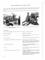
FINAL
BRIVES
Each consists of a pair O f gems ha VI‘n Q individual casings, mounied lateraiiy to the differential and driven
by it (Fig. 110).
Final drive overhaul.
‘ii
The majsr overhaul thereof should be made as .0 ows:
Removal from tracter (Fig. 114).
Remove the electricai cabfe energizing the rear
lighting from connection, and take ihe mudguard
away;
place the transmission casing on fhe stands and
remove the whee! assembiy, with disc and fire.
Remove the final drive casings frcm the tractor and
null outwards to slide out the difierenfiai axle from
bevel gear.
Shipping out of components.
v
1
1
.r
\
Mount fire assembiy on the roiary stand ARR 2284
with support ARR 2221, and remove the brake drum
fasfening nut.‘
E
Remove the drum using a universai puiler (Fig. 115};
remove boih finaf drive casing cover and driven
gears;
remove the axie inner bearing stop ring {see Fig. 116)
and push it out the casing.
i
Note. - The final driven gear remova! does not
necessarily require removal of the casing from
tractor.
To unscrew the driven shaft nui of the final’ drive,
mount £00! A 137014 to stop gear roiaiion (Fig. 116);
ihen use a universal puffer provided with 2 screws
5:
E
1;
\I
1|
i
{diameter 15 MB, pitch 7,5 mm} (Fig. H7),
I
\
Fig. 114. - Removal of final drive casing from tractor.
YO
Fig. 115. - Removal of brake puiiey using the universai
puller.
i
3:
1
<
%
-/
‘
i
L
1
1
Fig. 116. - Final driven shaft nut removed.
Fig. ‘E17. - Removal of final drive driven gear using
universal pulier (16 MB x 1,5 mm screw - 2 required}.
51
4
lnspeflfion of components.
Check the or‘! sear’ of the difierentfal axles and of the
driving wheel shafi‘, to prevent off feakage on brake
bands and fiom {he driving wheel.
Check “bearings for free running and iooz‘/1 backlash
(see specifications an page 'Ir’3).
Assembling,
When reasssmbling avoid damaging the sea! iocafed
in the chfierenirar’ bevel gear support.
BRAKES
The pedai and hand actuated band brakes act-on the puiiey keyed on the differential axies. The tractor
when used on roads requires sudden and quick braking and therefore the peda¥s can be connected by
a lock which ensures simuttaneous braking action. This fact must be born in mind when setting the
pedal free travei which should be equai for both.
'T‘.‘_“-»
_c-__:: Tjj-__
___
____
.._.._.
. "==~==
_...__k
\
'—z::3@ _ _. _.-._,~--—~»~—w_A___/*~—-.=
f
J
.,
_“\
‘"
‘*
/
A
_fi, _M__
\
"if; \
a
'
-1 1
§
.
.0‘.
kn)
'
\.-.-1.
9‘-1.9..‘ ‘u. ,‘.
IR!
nan
S» ii! ~
_' 11L»,
*1 _
94-‘=\I7‘;‘\\‘\\\\\1'vi\\&\
.‘ .
.:-wmlxom
R
\F
_\ 43
/
_
‘
,
'
‘" '
_,
3
A
-
fina-"_ ‘
»~ ~.
-
~:.*'_m*.s.s_-‘Q
"
/\~_ /'
\"?:;_<_=o_,__
-'
-
'
'
i
--\.
U
—’“‘ E’
.
r
I
F
. Q;
~
I -
i
.
* 1
s
~;tf»"
.t_
A @
“
Q
‘rJ
~l€.>>A|A.'
'%- -fir? , '1
-r
.
’“"“
.
o_
_|
|
i
//' ~
Z19‘-':1L_—.:,-
!\|
ruw
-
v
W
_
_-
-
Ix
’--
F
_
_‘__ .
_
_,.._--
R
h /
‘Q! _
;
|
rum:--._,;",1
. ;
;
b
Y
.
J, :_,_ {sa: -= '
Tm
'
Fig. 118. - Brake assembly, pedal and hand conircls.
a. Clutch contra! pedal assembly - b. Brake pedai assembly.
A ¢ Cievis lock nuts - B 1 Caps ~ R’ = Brake band centering screws * S = Inner arm - '1‘ = cute; arm - v 5 1,-me, am-,
fastening screw - Z 1: Brake band pivot pins.
.
’/Mmn?
5_;€_%__
1
.‘}\¢v¢;
4
J"/1:
Z
--
- J
5:'?'n1¢1Js /10!
1
,i> I A
.
'
‘m
1" I -
"'9 “73"'$/C
-
_
, -
.
“J v
flfca cw: $'f*1'1~<f’ 5% K-3 ‘ /530 “E7 ”‘
<~ /4»
5
/"°" J"
r
" .G‘'
V1.3
__:
:
§
. -
)2‘
-
71
i.
,
2
i
Brake overhaul.
1
i
r
To be performed as follows:
To remove brake bands:
— drain transmission casing oil and remove from
Removal from tractor-
the iracior the final drives, according to page ‘F0
instructions,’
- remove the differential casing lower covers and
unscrew the screws (V, Fr'g.119) remove the pedal
I
|
springs, remove the adjusimeni rod ends B from
outer arm and slide it out;
-— remove the braking band end pins from the inner
confrol arm (Z, Fig. 118) and lake them away‘.
w...
Checlr the brake pulley surface and rr necessary
iurn it down, avoiding faking deep culs which
would impair its resistance;
check the dlfierential axle seals for oil leakages;
correct any leakages smearing the ferodo lining;
inspection.
replace bands if soaked with oil using tool A 513007
for riveting;
in addition check the shall and pedal bushes for
wear (Fig. 113 a and b).
A/lake sure that:
Assembling.
'- ....13
~"
‘3.—.
.
~I5I:i». *:?“,'""
.~
~,
.~.
.1
‘
— the screws (V. Fig. 119) are fasiened by wire lo
the internal levers (5, Fig. 118);
— screws are facing the tractor rear end; if not,
'.
'
-
~’l\.e.'-'J;="'5“'2‘?>;?5fL-",.@1?.r;;§’E=;L’3s¢ " '1'"
EM: :§~":*
.,~.:;-,¢_7=""
=.,=§.='-:.?=l"'-I?
.
.\-
‘.=-.-‘.\-;<
\\.-
"
o. ll-ii"
‘
1. i
~.~#r.@&f~:.!1"
7*‘?
_..".'=-I-'_>,?“-.71-' r
‘
~ ~=<.~.-‘e
z’-'<'~!;.r,gZ--*2
‘J
r“=P’-.wl2-7»
.~,¢ ’_
Q» _; -'
*1
w‘
-
~*
"’.'_‘£.o-'
?'
'9 »
" . .
D
and no braking action would be possible;
- when mounting final drives, avoid damaging the
‘.
differential bevel gear support seal wilh the
differential axle end.
>-'<Y:~
.
l
, ., -_;,_. :; ,;;_;-‘
‘ . 11.___ .1‘-_w;*;,\<_
'
, '>;':.-<— '_ ‘ I ~ 2% .~.'.-.-.»..r. - -1»~,
. -
ll. v
~ \-.. '-'2 f"
,»_r »> 1 E~
.::-.'~-;.-;=’
,.-3=2'-,,:;», . Pu _ . . ~:j;
4 |
._>.,;../%=: ~9..
*
fie-.1-*~ :5 g ;;:; 1
..-~~=>~—<~.~.c.A.;-5/;=<;;:e:v.=':=.~;~5:,t:;*.i%i&.+,
‘ #5.
-"7
;' .lli R
’
?§,:-.=;’i.<.;=?:=*.‘;;".f;:=.>=5451;.l<:l:.ro:§;;§;;§I1i»"
A
,. {.3
-5-}=.n‘5'» :¢;:-.:.~:+;:.;i1:¢e$-§.-?-‘5§?=‘:
‘ _»,+;;=-,.-_,_"";,‘, 31» """.‘f"'__
Brake adiustment.
the exiernal levers T have been interchanged
1;
,
\
‘ ':%>
-..-
~:§=,_',;-~...;;—;;-;_:;,;3~.7,5.,
, v>..==';-#=:~i;.r‘
~‘ . ". ~=».<;_=-‘*
.. .o-'1
.1» I-1.
,_.
5
'-
ow-@;l
.
I
.
:
'
"eo i‘-J./'‘. ‘J=_;;;/"
-
,
Fig. 119. - View of brake hands ané ccmtrois.
'
A = Clovis lockouts - B = Caps - R =- Brake band centering
screws ~ T = Outer arm - V = inner arm screws.
When mounting brakes on irecior:
- unscrew [he two nuts and compleiely screw on
the brake band tenierlng screws (R, Fig. H9)
then unscrew {hem lhrouglv a complete Zurn, and
re-lighten the nuts;
- slacken nuis A and unscrew rods (B, Fig. 119)
until the free travel of each pedal is taken up, than
screw them again two turns so that the brake
pedal travel is about 50 mm (1 .969”).
Before adjustment, the brake control lever should
be set all live way down with respect lo the sector
plate.
72
1
l
I
ll
F-PE£ZiFiCATlONS OF BRAKES AND HNAL DRIVES
WWW
s
:
Final drive pinion and bulb gear tooth backlash
. . . . . . . . .
0,15 to 0,25
I
(~0.002G Yo 0.0019)
=
(8.287?)
Brake pulley diameter . . . . . . . . . . . A . . . . . 4 ‘ , _ . . =
I
*1
_ .-. -. . -
r
J
(£10059 to 0.0098)
-0,050 to 0,048
Clearance between driven gear driven shaft splines ané gear hub .
1
om
mm fin)
Brake band shoes thickness . . . . . . . A . . . . 4 . . . . . . l
‘
; Clearance bet-ween bushes and brake pins . . , . . , . . . . . .
1
0,5
(0.019?)
0,20
{0.D\'J?Q)
210
6
(02362)
0,120 to 0,144
(Q0016 to 0.0857)
I
E
_
l
‘E5’/-3-Lu. &'1Ca.
815:] -$1;
Wear limits
mm (in)
4
((131575)
0,4
(0.015?)
5;“ Pg?“
~l
l
_.<-. -.
STEERHQG
AME
FROM?‘
AXLE
STEERING BOX AND LINKAGE
.3
l
Removal and disassembly.
E
The steering box removal and disassembly should be made as follows:
l
Parts £0 be removed.
Operations and cautions.
l
The batteries.
The dashboard.
E
x
Remove if wiih ifs frame from the batéery box and
the gearbox;
detach the rear /ighfing cable from central cormection.
Steering arm from drag link.
The steeri ng box.
5/acken the 4 screws fastening the baféery box to
gearbox;
remove screws fastening the steering box to gearbox;
remove the steering box with the dashboard {lift the
battery box firsi).
Clamp the steering box in auvise and remove the following components:
$%@e-"ire arm.
Use puller A 735003.
Shaft and roller,
Remove the adjusting Screw 1'Q¢k,r7uf and {he ,0/ye,
F
5
shaft side cover (see Fig. ‘$23),
1-
73
EI
-_'I,|~>¢<;.aw=-u1~,\»a_<l/.kw&b1T
Remove the steering whee! and {he board; remove
{he screws fasiening the sfeering column to the
sfeering box and remove the steering shaft and ifs
bearings.
Worm gear shaft.
5
f
Mole. - When d:'smam‘lfng the ro!/er bearing
outer races from the sieering box, do not alter the
shim pack (S, Fig. 120).
\%
@ \=-a.
g,
~5_;T€—i
/-1-3
v,
V
)>\
'
.-<....,,__=_‘_'_
E I 3'"F‘f'.‘.‘.';\4»
--“‘\ \ \ “
~
i;. nxy‘
.-"
"-~
in
WT:‘\
$1
T
I5
;
:*~.:.'-sh:-1
7_;:_;
Ii e‘ 1‘ 1,3,2.
§12-_‘;. 1‘. =_’_
' ‘a
»..~T'1.*
»>:».;., 5
‘I:
e:‘:l"'*'J
5*
fie>4»'
“l-"‘ - Y-“.1?
2585?}???
-._--mm‘ —:;
id" '*17‘1'?"€ -T1
r-_=..A
:
L. =..-‘.1,-~
_.»,¢‘- .1.
Fae‘ '
:- m..--
3
in
.,3‘ . . .» -
.~,-'-‘,- I
\.
Y»I
.|_
’ §::.'=3.?\i~.'-"5
1.<,;__;;
l/,1;d_1i;l‘ r.:€‘_
§1- _l':.f':
-‘"=._ .;z Fl.1‘
~. ig._ Q ,
4;-_f~, _. ‘Q;
r-"
_, -:=;:;.. 5:
.,--
Fig. ‘E2<}. - Steering box perspective view.
R == Roller washers » S = Screw to roller tooth aligning
__
. 3
- ‘Kg-;»~
R
L
“‘\?‘I
:w‘:A;'
:i_fl"'
d
*i;'§ ~‘,;;' '.~e;:;_.5.,;§
~. ~, l
F
R
at
‘
J‘-‘An
;
~.m_1. ;~:_.l;-:1‘=-~ '.';.4.r,-W!. J
‘‘“Z9,IT‘I?».-; [f "'9;,
w~
.-.8lg:
C?
==-I-~ -.--—-1;:
".
_
I’.-
eh
.. ‘.—.-=1".-‘:"1‘---5-'
W
.,T‘
h“*1”we "ii~M.;.<.s':.=¢‘<
,
'_
i’
.2"?
.fi=
2%
'
’
£6 ‘$1!
..
.~f_::~*;*
6;
';.~__.:
.
,. ..:¢';~.';z_
3%?
.3‘;-'=
F5; , L? P*~‘:"E'=.‘
‘”'§;»\;»
'-'7" ~f{5!."=§Z%>!‘&1..~'§h¢"
-~.~:1¢~>:l
.1 .
—;. f»»\—. ’ _ _ ,1.
-. 1.V 1 . 1
.
"‘/'4‘-‘§4":=_‘>
.
so
,1
31:;
51115’
_~=.-.~-.__.__ . .
,.__§'"'
4-€'1~F
2:: <-,. ~, ‘ ---"25’; ‘ -- :;'.-=_-;'
‘
f‘i‘=‘.¢1..
V .;'
~12--’7€\;
'" ' '
_~.
.-Ir-.‘-"1"‘ '{=i'~17' W-‘*2 ¢-..‘:~'-1:‘ +1
.»; 3..
;._. -.1.-.--‘.~; .-‘.»- '
.;. .-.-;-;-.'_
--;-=7
-g
" :I._‘.J.','-1;’ .,
:_:_‘-‘-§‘1“::i€-__‘-I,-—:_E'
_';:l.;:n-1j1_§l:'
~;;Z€‘=.. - . .
_
-r
-.. =,,_
V
P
»- ;.~: V.
9;:
~rz‘;.~\29_'
T. '
1: "
$35.2"? .i'.",~,.=Il1=‘$Zt‘1
" fi“*‘»q='%=>-1?‘-""-n‘
-=-=:-‘.‘>':-":'»:§»,._. ' F
' ;.:"&=.“e—~"‘-‘.
--‘;4;;>;:r
shims ~ T =1 Taper roiier bearing adiusténg shims - Gg and
Gp = Roller shall seals » VI’ =1 Adjusting screw.
Fig. 121. - Steering box muunied on iractor.
hlspection of stripped out componenis of steering box and steeréng unit.
Check mating surfaces of roller and worm gearfor notches or traces of seizing. Check alignment of roller
and worm gear, this signifying that the roller and worm screw reciprocal position is correct; if otherwise,
the shims should be changed (S, Fig. T28).
Check for clearance between bushes and the roller shaft, according to specifications of page 76 and
replace bushes when iimits are exceeded, in order to maintain proper mesh between roller and worm gear.
Ream bushes after assembly, using reamer U 611916 to achieve the correct diameter. ‘
H roller shows end play, due to wear of the two washers (R, Fig. 122}, replace the shaft also, being the
parts riveted together.
l
Check the taper roller bearing for free play and the roller shalt oil seal.
v~+/
Check eieering arm and drag links for straighthess; if bent, straighten ihem anci make sure ihat their
strength is u nlmpaired.
-._ . -~. ,_. _
l
.- . _= -.
Steering box assembiy.
Parts to be assembled.
Operations and cautions.
The roller shaft bushes.
If bushes have been replaced, after reassembiy ream
l
l
l
them using reamer U 611916 up to fine rfiameéer
specified In page 76.
74
l;
'£
!
§. . . ._-.
lg
1;
l.
ax.»
-‘.:c>,¢.»c4;g-.u4_-
The lower taper rolier bearing outer races and
shims (S, Fig. 122).
To avoid eitering the setting of roiier and worm
gear, the shim pack S thickness shouid be varied if
ii
i
the worm gear, the roller or the steering box have
been replaced; the shims pack should the/7 be
J
.
adjusted as foiiows:
‘i
w
a) mount the worm gear assembly, after smearing
/*~-\
1
it with red lead compound, and adjust rj‘/f,-‘&(3_r;§Q
of taper roller taearings;
/ /
\
b) mount the roller, shaft, cover and the steering
arm;
5’’ 5':1
C} adjust theroiier and worm gear bearing afiggfds
ing to indications following.
z
4
¢";'£fq
'.'¢--'
.21?"
.
.
“ii”
*'¢
»~'/
-_.; .
.7
”-
_.-=.i-4.;-e
iv
.1
-4
|
Wf
it
"
'=.\
.
hi“\rer,
5
‘,-
new adjustment of bearings with shims T.
\*
if-_-.§__,
;.'
_, _,_.
.:5’
star»
J
Note. - Each variation of shims S, calls for a
* "““'*~
I
|
'
‘*1-_.t at
c-."-;“e~
-
=9 _,¢/,§'-er:-Tu.-_ \\-iu;€§§‘
6‘
“
\J
\_/
-' “
,
.
.1"-.-.’,.'.r..-.r—
fur
-»_...../ J
I
‘E’ “T”
"' "'
I
"l\
K)
_
_
>
‘
5',-\
1
'V - '
/
,
\
‘Ed/I g F
c
* ""
t
.. _
D
~5 QV Q
"
1.8
\ 5 ‘Q’!
1%}
2; ‘
'.
s
5:-:1:
5‘.
I
D
Q M
liiréjl
_
,,.
K7-
.---§
-_. _—- J 4
Fig. 122. - Roller tooth cross~sectinn.
R = Rc-Her washers - S = Shims centering screw to roifer - E;
T = Centering shims taper ‘nearing adjusting shims.
The worm gear, with the taper roiier bearing actjustingshims (T, Fig. 122).
Fig. 123. - Longitudinal section of rolier tooth shaft.
Gg and Gp = Sears - Vr : Adjusting sci-9W_
Mount the worm gear shaft with its bearing shims
and check it for flee rotation which must be ac-
complished without excessive effort.
The roller shaft, the cover and the steering arm.
-...,,
Adiustment of rofier and worm gear bearing.
The correct functioning of the mechanism requires
that the distance between roiier and worm gear be
as sm aii as possible and corresponding to the original
specifications.
To this end, after mounting the unit and positioned
the steering arm as in Fig. 122(this corresponding to
straight forward motion of the tractor) the adjusting
screw (Vr, Fig. 123) should be screwed on, in order
to take up the piay between roiier and worm screw;
in addition, check that this condition remains un-
varied as the steering wheel is turned 30°, ieft and
right.
After adjustment, tighten the lock nut of screw E/r.
To refit the guide box assembly to tractor reverse the dismantling procedure.
I
3
5
After assembly, service the guide box with SAE 90 oi! and the drag link grease nippie with chassis grease.
75
~., -y~,».-'=
Steering {@518-
After adjustment. check the steering wheeis aiignment with the tractor axis; nevertheless a toe—in of abeut
5 mm (0.‘|Q69”) and a camber of 2° are acceptable.
Check tightening of the steering lever baits and the cross tie~rod ciamps and check tie-rods and levers
fgf gtraightness, to avoid eariy front tire wear.
!
i
sP£c%r=z<:A"r1o:~ss, ASSEMBLY CLEARANCES mm PERMISSEBLE WEARVOF swaaams
mscmmssm rsvzsrasm BOX), "ma-zoos AND LEVERS
|
i
1
I
_
~—~ *
— *'
"f
"W
:
r
i
! *"
5
nah?)
I
,
mm U"
"'
'
"***
””""" 3
'
1
i
Assernbiy clearances
' '
'
7""
mm (in)
Wear
E
limiis
3
mm {in}
i
Steering box bush inner diameter
34,925 to 34,050
‘
~
Between steering roiler shaft |
0.3750 to 1.3160}
0,025 to 0,075
and its steering box bush
Steering roiier shaft diameier
i
i
1
I
i
"'
i
g
2
.
\
0,15
(00010 fio 0.0030] E
34, Q00 to 3d B75
~ 0.3740 xG 1.3.30) ,
(00059)
5
I
k
‘
i Coverbushinnerdiameier{afierpress | 34[g12m 34.93? I
ii
fining)
1 (13745 to1.3755) l Ba-.weera
‘
_
steering roiler shaft
"i
”” mi
i
Steering control rolier shaft diameter
34,875 to 313,900
1
0312 10 {L052
iwl anditsbush °“s‘e“"‘g hm‘
Cover
(00005 \° 00024) -
P .. 5
‘
moose)
‘
;
(153730 ‘I0 1.3740)
29,020 10 29.0729};
Y Upper bush inner diameter of steering
_ (1-1425 *9 31445)
i_, _ _
transrnissinn lever
_ _
i
_
,_ __
Between upper bush inner
diameter and ihe steering
' transmission lower iever
28,96‘! to 29,000(°)
pivot
Steering transmission ieverpivot diami
9421' (Section A-A, Fig. 126)
i
(‘M404 io 1.1417)
inner diameter of lower bush of steer»
mg arm
~
K
——
Steering arm pivot diameter
7
i
__
_____ _ _
_____________
‘
!
38,025 ta 38,087
¢
'
0.4910 to 1.-£995}
---z'
V
—r
—
|
" __
;
Drag-fink pivct djameier
=
i
¢
;
i
_
'
B EIWEEI1
,0
I DWQF b U5 h IHFEEF
.
E;
!
0625100126
i diameter
the steering 5- ((100.0
'6 10
. 0.0050)
'
arm iowerand
pivot
0'35
" i
_________i
M
12,000 to 12,043 ;
(04724 to 0.4741)
W __ _,_
Beiween drag-fink end bush
f and its paw
.
_ ________ _
ir
(00138)
Z
I
‘ Drag-link bush inner diameter
‘
'
___
_W___
0,35
(00138)
I|
w
! 37,961 to 32,000 1I
(14945 in 1.-mar)
___§
0,020 to 0,105 :
(00003 to 0.0041‘)
0i
__
_________
1
__,__
Mi
1
0,000 is 0,070
(mono to 0.0025)
0,3
<u.e11a)
‘
'2 1i,9T3 to 12,000 '
i (06714 To 0,4724)
‘_. .- . v~_
1 Note. - The steering arm upper and iuwer bushes shali be mounted into their seats on the support wiih an inierference
i
of 0,05 io 0,28 mm (CL0020 in 0.0091 in), bushes §or steering bu: side cover shalt be mounted with an inierference
i,
of o,o1s to 0,053 mm 01.0005 to o.ua2s in}.
'
Assembiing iorque sf steering transverse tiered ciamp screws is of 2.5 kgm {:83 ‘it.ib).
5
(O) The data are the pre-modification ones; the post-modification ones (from Tractor with irame Na. 402251) have been increased
of 1 mm (D.il391$“ in}.
76
€‘,.'\u.'_ _,.
i
-_. . _:»,/
i
'”i
FRONT AXLE
5
i
Checking the front axie.
. .\_.u_L, . _t
ji
s
Remove! (Fig. 124).
1
\
J
Piece the engine sump on a stand or hydraulic jack,’
drain radiator water and s/acken the rubber sieeves
band stamps;
disconnect the drag /in/< from the steering arm and
the radiator shutter control’ from its front end;
disconnect the head iamp cebie connection; fasten
the two ends of a rope in the radiator upper section
and insert wooden two wedges to stop front axle
osci/iation; remove the sump screws fastening its
forward end to the radiator support and move the
front axle assembly forward,"
remove the radiator cowifng and the radiator.
u
1
i
Dismantling.
Apply front axfe to rotary stand (see Fig. 125).
To strip it out refer to fig. 126,
Checking components.
Afier mounting the hubs check bearings which
should rotate freely without any noiiceebfe end play;
check surfaces and plays of king pins and of the
axle pivot pin with their bushes;
check the bronze thrust rings thicimesses and
replace them if in excess of wear ifmitsfsee table
on page T9).
*9
,f'7v-1:"
.
='
i
<
"\__,1 ,, ‘E ;
v
-,
-= _~ .e~:'%;é:‘<f2.e§T>=;Z;;~:-ea
L‘
.
~_,.
.-,_ -‘ .. ’.»,.%::»-1;.I’3€:fi‘1"‘
.-,-e-'~ _: -_=¢_;§-‘=,e;71-e-'
-. . , '4>r\' »=e:y-
'=-?s."* -_,_,-._v
:__ 1
5. e
' :__
‘-
~_
r
<P
~‘- 2-Zea‘
-_e_’~*e
»%1*r’
'.'5‘}I»'
I » —
-.~;' s-‘<9,
5--1‘.-‘~ ,3?
-;: .
_-1”--~.~‘,?~ {fix ’.-;,\~1¢F- ;=w=—.:_.‘/
' ~ , '
~51»
_ __,.=
"'1'-.-1
\~_»v~'L1=.*e‘%e5_,L$,. ‘iv
¢"“'"F!
7
if ea;
, _ "_._-
--
'5__;;_¢|-"
" _.,@.;_.—
ale". iv-;"
— _ 4.-.1-*5"? 1.‘ _ ».' ~=: 1;» -." e ,:!-
WWea:
..
“£1-i-;,"'11:5, e . ,.:E>. ;
‘lé.-fie,
e‘
. ;=.-::=<
‘e " '1,*.-.~ =¢
..»_!; -i1L‘l%“r'5i“e,
‘=;_l..§;;+-5-.-: _ 1
- .'“=.1--'3
"2
'1-'J;'§'§'~.::é=K;-¢_<1
f ;if!7:;1g? '36‘
‘
.;
1:-
!
e
e
.-;
/Q
K’
2:-as-1*;¢‘;=\. \-.,sI1\‘~- -'/
“r ""§r>.;§_
,.,,,~.
.2-» “ _ --
Fig.124. - Remove! of front axle and radiator from engine.
;E
Fig. ‘I25. - Front axle mounted on rotary stand for over”.,_ ~-.<_+,\.u»e-,'_—.~»
5
2
3
>§
hauling.
§
§
77
¢~.-w»-,~=.-1»~?-
JVZ Z/‘I3
I
1"
4&3.‘
/
>.,2
bi
r5
‘i
'\
'\_l
_
-1
4
“
x '~" £__\" I
~.- ~r9V\V 1/.»
v-_\ J 1?’;/1-'-'-’\f-r\:/>.J:\';§-/r.\r 3&1
, ;~\;;.;\_;.-i-q\'_
“.".;, ~__>\""._;_- ._._.-.c,::Jw__....».-um" .6-“>3. .g;,..___...-:1;/__.a,,1;gfi"'~€-104'?-4'Tr_¢2E/1 i»
1
"
\1!|\x
m.Q
w1»--'
-fmm“
"'
l
~_\..
.; .m_
i .
- £3
i
i
‘___‘_:*
_‘_
.‘__~T__-_
I
‘
‘i .x-=~*‘**‘“““ ‘ ““~\u.
mam‘
4
| 'd. _»/
'~
\='~.~' :.-;_‘~T:r
$19? d f‘
;
L
is
_ _,_,.»
W
._/1‘-M
I
1
,,_ A
;,//
‘i
1
‘
:n4e,,.
4:-I-h
4v.,,-4___’£.:'.; ?’
.e -ma».
j./{’*"§._i‘j._s;,;":>\
ex '¢"/ arms
_\ "‘ "~
sq
i
ill
l
-.;§
1,_.._
'
"~<%-7
.,.
F“ “
1
"1.
'1
-
z
_\ ‘ . ‘
‘Z
I‘
~
"e.
In .
~Ii '
I‘
-
I
'
9%
‘u¢;,\ \\\$ \\\\.\»>\
‘-\;\w\\ 1*‘
I ?
-
was
v...
J
Sect. A-A
i
_ _
. » . i,—;_-;=;.§-.-;-r_>_ -.—~-€—-1'--in-:-1~'c<'v.-iqif "
é
é
i
I
.
Z
. - . ,_._ - —.
KJ
I
"'\
unnmnonm "L ~
.
_-.J_ _
Fig. 1&3. ~ Front axle section.
Check the wheel nub cover rubber seals which must
ensure protection against slush and moisture infiltration from outside into the bearing; set near to
the wheel a surface gauge and rotate the wheel to
check the disc and rim for deformation: this check
concerns both steering wheels.
Check the camber of the steering wheels by laying a
square in the vertical plane along the wheel axis,
and checking if for any two opposite points on the
rim, the difierence between measured distances is
constant;
_
check front tires for wear and replace them if their
central steering ribs are too worn.
I
i
!
Assembling.
Assemble axle according to Fig. 126; no difilculty
l
should be experienced.
Note. - The lower bronze thrust bearing of the
steering knuckle shall he installed with its lubrication
passages facing the steel upper thrust bearing.
End the assembly by greasing the hinge pivot, the
steering knuckles, the front wheel hub cover and the
front wheel hub with chassis grease.
78
E
E
SPEClFlCAT'!ONS, ASSEMBLY CLEARANCES AND PERMISSIBLE WEAR
FRONT AXLE COMPONENTS
§
1
ii
4‘
~
9
J
Data
mm (ml
1‘
\
,‘
. _ _ ._ ‘ .
3
1
1
Axle hinge pivot bush inner diamtfzer
(dimension to be obiaaned &?ter
bush press~1‘ittir:g) (1)
1\
w
‘
\
"
W
W’
l Min
WW '
W’ "
‘ Axle support thrust HFIQ
-_ t h-ickness
mm (in)
'
f
31,975 to 32,660
Z
(12589 to 1.2598)
hing!-1 Pivvf
3
‘
\
'
‘
0,025 to 0,112
0,35
f (0-9019 '50 E‘-99“)
Q
(onisgég is gfigso) _t
we”
limits
mm (in)
:
. Between bush and from axle 5
‘
;'
_
1
’
\
Assembly cfearances
‘
32 025 t 2 08?
H5603 is iéfiss)
Axle hinge pivot diameter
>
1!
1
1
___
I
‘
‘
3
___
‘= thickness
fiftinimum 2 ‘
‘
1
\
_
(OMS-B)
{0.0?87}
Y
.
1
5 Sfeering knuckle bush inner diameter
38,025 to 38$”
(dimension to be obtained after
(_M9?0 to 1.4995)
;
1-
bush pressmflng} (1)
A-" * '
'
Steering knuckle pivot diameter
a e nv ear:
'
<1‘sa m .. bush Inner
'
'
-i
37,975 to 33,000
‘
‘ eter and king pin
@025:
,
0 cm
',
g5
(011010 ‘:0 0.0044)
ass
,
£03138)
1
(14951 EC 1.4951)
1
1
1 Axie thrust bearing cup thickness
Axie hinge thrust bearing thickness
v
\
n
-
3.925 to 4.600
(031545 to 0.1575) 1;
5
1
1
Minimum
0,91 10 1,09
_ 410.0358 to 0.0429)
_
—
_§
—~
jthickness 0,6 §
g
(0.022:-5;
1
Minimum
»—
thickness 3
(Q1181)
11..
W
WK.
._;_W
_ ,_ _,_
(1) Axle hinge pivot bushes and steering knuckie bushes shall be mounted into their seats with an intederence af 0,05 to 0,23 mm
{c.0020 to 0.0091 in).
1
I
|
1
\
E
w
i
1;
\
I
7
>
I
1
1
J
|
\
79
>
p
_.é_._
"-
OI
“’~“* ——~ev ~:-~M.'\m'~f‘-.
c
Z ‘
1
M
til¢t~§|§izls§:1:l*&=@ @g:l:|=;§l;
B
1
Q
<1
nr (3! cf
E
8
l
T"
~
r-J
1
Yc'l{wie::_ Slack
L'“'
__
j
‘
klluw
__8r¢L
"'_(— II
"O
_'
_ -6: =1- - . _¢l},;_.j=},_ _ _; ¢,:_'°——I-¢l'»;__»';__ §:fi\‘t1€12=3‘.§|.
7
___U|
‘
'
I
P
Brawn
I
'
»Z
"
‘l"
_--_-'*'fr--—*r
l
‘
U,_. _ ,
_
.
l
c:::.»—
PC
so
‘I
Q
§ l;
=
'1"
Brren
2 .1a
1
‘i
r(».T\—
J
_¢D@~. M._ .
lB
G]
‘l
1'24! | JCIZ
'v _
l
‘
1
39% 54/2
:
=l
"1]
n.r‘h
Sn 6?,
I
2
"A
Qt FPG
_
C1~r'
, W’
GreL
' "'7
_
fit
h
1
,
Blue
W
L-@¢?B>"j
.
.'_""""—j'
Ls
I
£&lu<-I
l
5§3
F
.
r
-
=
-_.,- *_.
i
1
'
!=r=1
L?"
_
7, *___m____ l
‘E:
l <6;___.._ |___-
l- H_
iii»
__‘_ __V_ B|=c5___
J
r
.
L4_ it
uni B'.;t\:____~_~i
‘
I
f
I
9-‘own
7 ”9{="*"\ r
Y
mu
:
-.r»~4. _=.t~-.M-~. _ . _
il
50a
.-_ .
. 56b........i'_ I
__
,
1
m1.!@
.
51
V:
lbw.T‘
. _ _ “ (“I
and 2 Elazk
'
Q-‘
I-»—1-~—- I
ac:
Green
l
1;
‘
|
* “ 4i‘
»—
_;..._.__
_., _.,,..:[._._.,.
I
I
1
gr)»
_.-_. -. -O l
a=r
I1
r.
l
l9
-
*»**=5.#-54
_f_ ;
M.__i.W____ ..Y
::_’__,.,_
.
-
W >__
_
_V
_V;_r_:i
l
,i--..~...--4
~
mfg
FPT
12]
-*
F
Yeiio
Fr — ~~*~'
Lf -
ii|___.;
‘W
~
Q
T’
q§_l_9__*-
if-‘-*-—2?
GP
"
and
Black
‘i—'—-"3
,
— -t— ~'.'¢70— ;-
-
——-—'-—-~--—--—--
/l*_‘
:~-&‘§§@>rl%*-
PR
W |..
r;=>
Fig. 127. - Electrical diagram cf tractors series 400.
8. Generator - M. Starting motor - C. Glow plugs. - B. 12V Battery - A. Horn, optional ~ PA. Horn button — FPA. Horn
i
fuse - P. Headlights, with a 5€J_='1.‘5 W bulb - GR. Control box - PC. Fuse box ~ FPG. Control bax éuse - LS. Battery charge
warning iight - F0. Dashboard lamp - CLA. Lighting and starting key switch - CA. Starting lever switch » FP. Right taiflghl ~
' FPT. Combination number plate and lelt tall light - GP. 2-pole socket - FR. Rear lamp (optional).
1
»
80
&l\bAI-v.y<wAflQ\:-‘fl$'ALr€tQ.»\&l1HnJ‘~AZ.X1<Ja4lt-Dn~EI.\M3aflY»!‘r¢.’A
rF‘
at.5
E
ELECTRICAL SYSTEM
DESCREPTION
The tractors belonging to the 460 series are equipped with a 24 V system, including generating. starting
and lighting units. The diagram of Fig. 12? includes:
No. 1 Fiat generator {type R 115-Mt},-‘24-1600 Var. 2), HG W, replaced by a generator type
DC115f24[7!3 C starting from engine No. 005045 up.
No. t Fiat control box Mod. A53-140,l2f$, replaced by a Mod. GP 1,-"24,!7 unit.
CAUTHIEN: The control box Mod. A,"3-140,-‘24 may be used with both generator types, whilst the
GP1,"2-ti? unit must be used with generator Mod. DC1'l5__~‘24[7/SC only. See details in the respective
chapters.
_
— No. T fuse (16A) for the control box protection;
»- No. 2 batteries (12 V), of 54 Ah capacity at 28 hrs. discharge, connected in series;
- No l electric starter (3 Kw) equipped with a solenoid Mod. E115-3124;
-~ No. 1 five~position starting and lighting switch;
~» No. 1 three-position lever type switch tor starting and glow plugs;
-W No. =1 glow plugs (140 W};
— No. 2 three~light headlamps, each with a 50,145 W bulb for driving and passing lights and a ll) W bulb
for parking light‘
— No. 1 dashboard lamp with 10 W bulb;
—- No. 1 battery charge warning light (10 W) bulb;
-~ No 1 fuse box with tour SA fuses for equipment protection;
-— N0. 1 tailight with ‘ll? W bulb;
‘
~.» No. 1 combination number plate and taiiight with 19 W bulb;
— No. 1 two~pole rear socket;
.
—- No. 1.rear floodlight (optional);
— No 1 electric horn with push-button control and 8 A fuse (optional).
Lighting and starting switch.
Each position of the key on the switch corresponds to a_ circuit, and precisely:
—— position 0:
30
3011
- All circuits off;
~ position ‘l:
30-51
3[l_./1
- Starting switch - battery charge warning light;
—— position 2:
30-51
3011-58
- Starting switch - battery charge warning light - front
parking light ~ dashboard light - number plate and
taiiights - two-pole socket - t00 mm dia. floodlight
with built-in switch.
81
C
‘t‘rlI‘.T.~T.“L‘:-;l -F 11% ‘
— position 3:
30-51
30/1-58-56%:
-- Starting switch ~ battery charge warning light - tron’:
parking lights ~ dashboard light - number plate and
.
tailtghts ~ two-pole socket — 100 mm dia. tloocllight
with built in switch - passing lights.
e
I
I
- position 41
£51-56a
3611-58
-— Starting switch — battery charge warning light - front
parking lights — dashboard light - number plate and
tailights - two~pole socket - 100 mm die. tloodiight
with built-in switch - driving lights.
The key can be removed when at position 0 onéy.
Starter switch.
The starting switch operation is dependent upon the position of the combination lighting and starting
switch.
. , .r .. ,m_.,-._,._ ,. >-.
Each position of the iever on the switch corresponds to a circuit, and precisely:
~— position £1:
15/54
—— All equipment off.
~— position ‘t:
§5;'54-19
—— Glow plugs.
~— position 2:
15,r'54-‘E9-filla
- Glow plugs - starting.
The lever returns automatically to position 0 from levers 1 and 2.
i
i
s\
Fuses.
The equipment belonging to the electrical system is protected by tour 8 A fuses contained in a box pieced
near the dashboard and by two other tuses.
I
1
I
i
— Fuse 54,3 protects:
L. H. side front parking light - R. H. side taliight ~ 100 mm die. tloocilight
with built~irr switch.
— Fuse SUEZ protects:
Driving lights.
-— Fuse 301'? protects:
Passing lights.
— Fuse 54,"2 protects:
R. H. side tront parking light - dashboard light - L. H. tailight and number
plate light ~ two-pole socket.
—~ Other fuses
1:
-*w»v'-e—wr_»~=.<-w>»~.=¢_,-».~r,_
protects the control box;
protects the electric horn (optional).
The generator with spy-light, the starter and the glow plug circuits are without fuse protection.
-\ QM»-,. @r—.< ,_~.w_,.
Find the cause ot fuse failure prior to repiacing a fuse.
-vu».~ \<¢--ul.>»no1\-=.|~rum.s_-'
B2
1%--~v\ —
1
1
§
§
r,.
g .
3*"
Q Y.
3
=!
.,it
1:
GENERATOR TYPE R 115-140;'24-1600 Var. 2
2
='\
Specifications.
'?jd:1LE‘~f;
7;/‘W7 éffififjd
1'00."-*1 fin)
Fiat generator type R 115- 146,!24- T660 Var. 2 (see fig. 128) having the foiiowing specgifications. has been
mounted up to engine No. 005644; it has than been repiaced by generator type D(3115_/24,f?;'3 C.
Maximum continuous output (24 V) . . . . . . . . . . . . . . . . . . . . . . ,
Maximum continuous current output (Ampére—fimitaf:ion at 28 V) . . . . . . . . .
Speed at maximum continuous current ouiput, at 24 V and 20° C (68° F} . . . . .
Maximum continuous speed
3:
‘r
. . . . . . . . . . . . . . . . . . . . . . . . . . .
Excitation . . . . . . . . . . . . . . . . ‘ . . . . . . . . . . . .
Direction of rotation, as viewed from driving side . . . . . . . . .
@
O"1\
3e2.A»-A
/
i;
E:-A
31
_"?'1. 1.
i,
~
'
Err ~..\
"
‘
r:§<’,ir
on
‘H
1]
A fé‘
\J\
shunt
cfockwise
.
A53-14-0j24
V
/K
I /
..»
,
,
4%;
_. ii‘.
4|;
5.,
6' /1.64%“
‘\§.__V. _
\
/
J’
/., 7
J\
§gH_».
:\ua1\¢~Hé\-';’
(‘W
, 2
/Ix-r _
1 -
g,
‘
7 7
1
__ \
,
r; __
6
‘_-
n|
o
:._
:5“)
'
_.__,iV;"::
'
W5!‘
by
*%\\~-av‘
T
‘T’
5,
- av.
lip‘
,
_'“"oi‘
I
o rrio M
-—-‘W ——- 5
%
1")
7: '\
I
}
i
K
5»'2
9592
5*_
1,_L
‘-.
7i 1
"
Tr
‘—m-ii’ -~M_~_--W“ I ~
, 4
I
@
/
'9?
4
u
W
|,._._..-__..._,
1%
~
=3 In
‘I’;/fit
/‘Q1
‘
_._;
4000 R.P.M.
. . . . .
Reguiator group type . 1 ". . . . . . . . . . . . . . . , . . . . . . . .
.:‘. .,.:§;,.A
‘HG W
4,75-5,25 A
1400-1880 R.P.M.
~:~:n»:~1¢,U1
-(Q.-[$3
\
@%\\@
/2
‘
“J“
+9
as
".~’
Fig. 128. - Seciional View of generator iype R115-Ԥ48,"24-1EDO Var. 2.
‘Vi
L Radial brushes - 2. Fieid coiisr - 3. Pole shoefasiening screw - é. Pole shoe A 5. Driving side support » 6. Frame ~ T. Armature 8. Comrnutatcr ~ 9. Lubrication wick - 10. Lubrication chamber -_11. Field coii terminal.
Bench testing the generator.
r."4u=-I."-hnair‘
Test generator efficiency, according the checks Jisted hereafter:
Generator shoufd aiways function coupled with regulator type A/3-'14€!,f24.
7\
E
-<..._
Generator tested as a motor.
The arrangement consists in connecting fermfnais
67 and 51. shoré cfrcuifed, as shown in Fig. 129.
\ 5;
Generator shaif be fed as an electrical motor aé 24 V.
K“
Check that afasorbed current, under such a voltage,
is 3-5,5 A at 9504150 R.P.M.
A5
g\
As test is finished, immediately disconnect terminals
Q
~:—!.-=\_¢I,M-\_<;.n,o_q
P
=s
a
,=‘\
1
e ,>.
, 1
moJ9
/-~r-M-*2 /r 1._
57' and 57 (short circu/Ted), to avoid damaging the
V
fieid coils as generator speeds up.
AG
Q
\
\
.....L__
Z
¥--r
ML?
E-a
Fig. 129. - Wiring diagram for testing the generaior as
a motor.
G. Generator ~ V. Voitmeter, 30 V ,€op reading - A- Amrneter,
top reading. (B?-1?9='5' should suppiy slightiy more than 2:1 V,
V
as current is TA).
=
f-Inna»
>-;J~_-M.ur1:u =.-M,
83
’|
i
s
The output curve shown in Fig. ?3B has been obzfained
Chegking generator output (constant voifagel
with generator heated after a period of operaiion.
Therefore, before plotting the characteristics, mouni
the generaior on five tesf bench, according to diagram
amr>@r@_
,__
of Fig. 13%; rim it through a moior for about 30 rml
.— .1 —- en
*1 i‘ § _
‘J
nuies, at 20-00 R.P.M.
The current output (5-5,5 A az‘ 28 V) shouid be Sup-
_*_i_1_.
piied by a rheosiai,
Siop generator, and disconnect ioao‘-rheostai. Fioéaie
44v4“\
5——;
_
‘
\
E
4
‘
|_.T____
‘
I
.
W ‘
3.
Q.J>(<€?Y‘_.,..L 1
37
2; _
‘
_
r _*_
1
_ 1.7%
_
,I
\
er. I I
‘
‘ .‘_ .____Ti
o . 5.
‘ '1
0
_
,
P
-/ \
- _-._ -._,__ _ _r____
_ ,. 11>
_
__
EGG
L\‘;
—
I
Such e speed represenfs the cui-in speed {hot con-
~
__
a
_
ditions) and shouid lie between 1230 and 1360 R.P.i‘vi.
(points on abscissa ~ diagram of Fig. 139).
W
__ _______ HM ii W?’
1‘
7
»~--.
i
r,
1
\
3
‘l
~,e-§i“i: :;:; ;§§“
_o ii
ier;
—nv-~V6on~-;e:-_ ; " : : : :iTfi: mom“o ;om o-._.:~
; u._ L.mL._ >
E
E).§;.:_
.,._.‘
_..1.‘_ _, _ _wi;_ _
W_.w _o . T..- /\
“M1
“‘4W4; 4 1
_i
generator, graduai/y increasing ifs speed uniii ihe
voiimefer reads 24 V, Eben measure the generator
speed.
F568
Fig. 130. - Output curve of generator type R115-$40_!24$603 Var. 2, when warm.
Sfop fhe generator, inseri the /cad-rheosiaf, and
meiniaining constant fise voltage, check againsi the
various speeds fine current values included in the
cross-haicheo’ area of diagram in Fig. 138.
Diagram piofiing should be made rapidly when
generator performance is beyond iés rated output
and therefore overioaci mighi damage ii.
{Cut-in speed at 24 ‘v'.: 12OD»‘lé(}0 F?.F.M.).
i“m“%__‘=
I
’}I‘~
'1"
m
’
G
\/“"1 “
_:o 21 57 51
'\
,
+
i
=
e—Jmn@
._-M.-M;@.- _- _ _
IL,_
it- - - J
.q]..L..e_..
_..
e ‘r—\£l§1$2l.:Q ./‘-3;"Q
HG-_
;
Kn”
K/LP
"W.
it---if
\\J/
_
Fig. 13?. - Wiring diagram for the output curve pioiting
{ampére versus R.P.M.) at 2 constant voitage of 24 V.
Fig. ‘I32. - Diagram of connections to check genaraior
heaiing.
Ni. Generator actuating motor - G. Generator - V. Voitmeter,
M. Generator actuating motor - G. Generator - V. Voitmeier,
30 V top reading - A. Amrneter, 10 A top reading.
(The reguiator group to be coupled to the generator should
30 V "lop reading ~ A. Ammeter, 20 A top reading.
be of the A;‘3-140f24 type).
Temperature test.
if in doubt es lo the maximum temperature of the
generator during operation mount if on the iesi
bench, with pulley and regulator group, according
to diagram of Fig, 132.
Run generator coring 45 minutes at 2000 R.P.M. and
during Y5 minutes at 4000 R.P.ii/i. supplying to a
resisior a current of 4,95 to 5,55 A at 28 V.
Overheafing measured by pyromeafer, should be:
— on generator frame: 45° C (113° F), or less;
W on commuiafor: 90°C $794" F}, or less,
84
<,.LZ'lZ‘IlTl;'
Checking ohmic resistance.
l
Field-winding resistance at 20°C (68° F) should be
7-<!.5 to 15,5 ohms, and may be measured between
termin ai 67 and ground, when generator is assembled.
Armature resistance at P0" C (63° F) is 0.520 to
it
0,545 ohm; it should be measured only exceptionally
to avoid damaging the commutator bars, owing to
the soldering of two pieces of wires spaced of 780".
i
l
Fig. 133. ~ Field winding test.
(Connect the measuring instrument ends to terminal 67 and
to ground).
>.' ;.~-.l '-4
l
l
l
l
Bisassembly.
Proceed as follows:
- remove the commutator head, disconnect terminal 67, unscrew and remove the through-bolts:
1
cl
1
-» remove commutator end bracket and slide out the armature with the other bracket;
-— clamp armature in a lead-jaw vise and remove the drive pulley and the remaining bracket.
Troubles ~ Repairs.
W. -ew. e-l. .
,‘ l
l
l
l
l
Battery charging faulrs may be due to:
i
~1‘auity generator;
- other trouble in the system.
l
l
Make sure to locate trouble first. The tell-tale lamp may furnish an indication with engine stopped or
running at different speed rates.
if the generator is faulty, the cause may be sometimes found elsewhere, and particularly in the regulator
group or in the circuits; "therefore. the operator should take care of generator efficiency and also check
the regulator §?oup and the whole system in order to prevent repetition of the generator trouble after its
I
lI
l
l
reconditioning.
The battery charge spy lamp may be helpful to detect trouble. li when introducing the starting and lighting
key, and setting it’on position 1, the battery signal lamp remains lighted, the generator is normal; if
engine is being started and accelerated to a given speed, the light should go out.
i
-
l
If, on the contrary, the lamp goes out only when engine has reached high speeds, the trouble may be
due to faulty windings (grounded or short circuited), or to the armature.
Generally, the higher the R.M.P. rate at which the charging begins, the higher the potential damage.
ll the lamp remains lighted, this indicates an interruption between the generator cables and the regulator
group; or shows that the group contacts are oxidized, and internal connections dissolclered; or that some
generator coil is interrupted, or completely grounded.
ii the above procedure leaves the light out and the trouble persists also after replacing the bulb this
signifies that the trouble is to be found between bulb holder and switch, or between switch and the con-
l
l
nections oi the components branched upon it.
When the battery indicator light goes out to go on again the engine speed being steady the fault is probably due to the regulator group or fuse or to‘ the electric connections (the jacks),
i
85
is
§:
Generator repairs are to be carried out as foilowsz
a) Brushes.
li broken, chipped, or worn out, replace them with spare parts furnished by the FIAT Company ~ Sezione
Ricambi. Be sure to avoid the installation of other brush makes, as FIAT spares only can ensure a regular
and iong lasting operation ot both commutator and generator.
b) Field-winding.
A
Check field coils by circulating test bench current though them (Fig. 133) and measuring the voltage and
the current with the bench instruments, then calculating the coils resistance.
I
1
if connections alone are interrupted, repair them carefully; but it the winding is damaged replace the essembly with a new FtAT spare. We do not suggest maicing {laid coils, as a speciai procedure i§‘requlred.
Poie-shoe’screws shouicl then be fully tightened to set the air gap at its previous vaiue. Reboring cf
poie~shoes must never be resorted to, if the air gap (see table on page 87] is not obtained; we advise
warning up somewhat the coiis, which are already shaped, to facilitate their installation.
0) Armature.
Commuiator. - li commutator bar surface contacting the brushes is worn or out-of-round, turn down
the commutator. Be careful when fixing the armature in a lathe and centering it, as the instailation
of armature assernbly between centers is not possible. Commuiator centering should be most accurate,
as commutator out-of-round, measured on brush ways should not exceed 0,01 mm {0.0004"). After
commutator turning undercut the mica between bars using a saw blade to a depth of 1 mm (0.0394”}.
l
Armature winding. —~ If damage is in the armature winding, replace the whole assembly. it is not advisable
to attempt making a new coil, as a special procedure would be required. Armature checks are to be
made with the instruments illustrated in Figs. 134 and 135.
i
1
4
i
i
I
Fig. 134. - Checking the armature with twin-contact tool.
(The interruption is located by the no indication of the
ammeter).
Fig. 135. - Checking the armature on the testing
apparatus using a blade.
-._. ._t.
(Blade vibrates at short circuiis).
l
4
1
86
n
=
Y
-5
_’J\
.0
Reassembiy of generaéor.
5
i
After any repair or replacement and before reassembiing the generator proceed as foiiows:
.;'
i.
a) biow away aii dust — chiefly carbon dust — from aii components. using an air jet;
§|
b) oiean brush hoiders and the commutator end bracket from grease and carbon dust deposits, using
_;r
a dry cioth;
Ii
"
3.
0) ciean commutator surface, removing carbon dust between bars. Avoid using emery paper or cioth
soaked with gasoiineg or soivenis.
d) check brushes for play inside brush-hoiders, against the vaiuee iisted beiow:
;.u~.,_
ii,
—~ cross clearance
i
—~ and ciearance
. .
. .
.
.
.
. .
0,1 to 0,3 mm (0.603? to 0.6113";
. . . . . . . . . . . . . . .
i1,2’:o 0,5 mm (0.6£i78” to G.0f9?”}
e) check brush spring pressure which shouici be 69 to ‘F6 kg (1.521 to 1.675 1b.);
1‘) service with high meiting point grease the baii bearing, the commutator and bracket bush and the
recess at the end of the bushes (Hi, Fig: 123) and replenish with oii SAE 50 HD the wick of the same
bracket
ii.1
The sequence shown in the chapter << Covering disassernbly» shouici be reversed to reassernbie the
generator. Mind that when assembiing the drive end bracket, its introduction may be facilitated by holding
iateraiiy both brushes and springs.
-
emu
After reassembiing, repeat the functionai checks as shown in paragraph << Bench testing the generator»,
‘*'"~i-urg;_.
I.
1
FIAT GEEERATOR R 115-14€];’24 - 1600 Var. 2 - SPECIFICATIONS
;
Items
i
Values
i
&
-_.a~mi.2~_;.-g‘SA
~ ‘,-<-,4
Operational test as motor
.- _~.¢-.
“ _-sew-L
' Running genegaior before piotting oi the curve (hot condition-run duration: 50 minutes}, amp. versus re-vs . . .
.-§A.- _
Ti
r
.
.
.
.
.
.
.
.
.
.
.
.
,
.
.
.
,
.
.
.
.
.
.
.
.
.
.
.
.
.
.
.
.
.
.
.
.
.
.
.
.
.
.
.
.
.
.
.
.
.
.
.
.
.
.
.
.
.
.
.
. . , . . r.o.m. 9504150
. . . . .
Q4 v
. . . . .
3-55 A i
. . . .. f.§3.rn,
goon ‘
. . . . ,
28 v
. . . . .
5-55 A i
oi 4:“: min. ai 2006 r. .m.
. . . . . . . . . . . . .
535$ 0,3 A I’
. Voitage . . . . . . . . . . . . . . . . I
QB V i
i ‘ Commutator temperature
(
‘ Resistance, at 20°C:
—fieid-coils
3
. . . . . . . . . . . . . . . . . . . . . .
3'
— armature . . . . . . . . . . r . . . . . . . . . . . . i‘
i
r Commifiator bar maximum aiiowed out-of-round . . . . . ‘
r Brush duration
1
5
.
.
.
.
.
.
Output current
_‘ 1-leatingtesf . . . . . . . . , A . . , . . . - K
~
|
r
.
.
.
.
.
.
i .~ R““m“9 ' ' ‘ ‘ ' ‘ ' ‘ ' ' " 3 of 15 min. afi woe r.§.m.
._._‘.,-_/;M. ._
I
Speed
Voltage
Current
Speed
Voltage
Current
-
. . . . . . . . . . . . . . . . . . . . . 5
I Pressure by springs on brushes (new)
. . . . . . . . .
_=
increment . . . . . . . . not more than: 90° C (£940 F} ‘|
Casing temps-raiure
'
increment . . , . . , . . not more than: 45° C (1130 F)
14,5-15,5
i>
ohm.
0,520-0,545 ohm.
i
0,01 mm (().0OO39”)
i
0,59-0,76
R9 (1.521~‘i.675
1500-2500
hours lb.)
‘ Brush cross clearance inside brush-holders . . . . . . . ‘
Brush end clearance . . . . . . . . . . . . . . . . . .
r Diameter between poie shoes midlde fine . . . . . . . . i
0,1-0,3 mm (0.I3D39”-U.0f18")
0,3~0,6 mm (0.011?-0.0235’)
70,6-?0,8 mm (2.'I79” -2,737”)
Air gap . . . . . . . . . . . . . . . . . . . . . . . . .
“ Tightening éorque of drive puiiey not . . . . . . . . . .
0,3~Ei,-$57 mm (0.Q1i8"-0.0186")
7 kgm (50.63 ft.ib.)
r
S7
l
1
q
r-.H.n-,w.~
GENERATOR TYPE DC ‘l'§5/'24,"7;’3 C
Witt‘: -Eli» mm’ {O-Q it M)
Specifications.
The generator type DQ115124/7;‘3 C, illustrated in Fig. 136, has been mounted beginning from engine
No. 005045; its specifications are:
Voltage
. . . . . . . . . . . . . . , , . . . . . , . . . . . . . . .
Maximum continuous current (ampere - limited)
24 V
. . . . . . . . . . . . . .
‘I A
Maximum current . . . . . . . . . . . . . . . . . . . . . . . . . . . . . .
Maximum continuous power . . . . . . . . . . . . . . . . . . . . . . . .
8,5 A
195 W
233 W
Maximum power
. . . . . . . . . . . . . . . . . . . . . . . . . . . . . .
Cut-in speed, 24 V, 26°C (68° F) . . . . . . . . . . . . , . . . . . . . . . . . 1550 to 1550 R.P.l\fi.
Speed of maximum continuous current, ‘FA, 26°C (68° F)
Speed of maximum current, 8,5 A at 20°C (68° F)
Excitation
. . . . . . . . . .
. . . . . . . . . . . . . . . . . . . . . . . . . . .
. . . . . . . .
Regulator group
. . . . . . W25 to 'lB'i£i R.P.Ni.
. . ‘£776 to i930 R.P.iii'l.
58% R.?.M.
. . . . . . . . . . . . . . . . . . . . . . . . . .
Maximum continuous speed
Rotation (trorn drive side}
.
ciockvrrise
shunt
. . . . . . . . . . . . . . . . . . . . . _ . .
i
A""‘-$46124
. . . . . . . . . . . . . . i . . . . . . . . . . . . . . . . . type ;
’;P1,.24!7
i
I
r
Main features of this generator compared with the preceding one are: completely enclosed, more power,
reaction type brushes.
Reaction brushes are advantageous as vibrations against the brush-hoiclers are reduced, compared to
the radial type.
.
For equal brush sections they allow a larger contact surface on the commutator, thus reducing both
sparkling and temperature: the excitation current also ls reduced, and the regulator group contacts,
\
voltage and current regulators have longer life.
When the generator is coupled to regulator group GP 1,-‘24,|’7, starting (cold), it may generate a current
greater than the maximum one; but it is reduced when the internal continuous running temperature has
3
i
reached appropriate levels {thermal equilibrium), without any damages to the components.
The feature is due to the current regulator, which, as explained when describing the regulator group, is
thermostabilized.
.A
V
an
2;
=
i|
|
I~
.,
‘y
:1
“J-T""'
en $1~
"“il'* l
l
1
“Ia I
GI:
Id»
can
/ ~\
E
l
&""'i-'1
J r
‘
"
'
'
____
1
I
Z
I
<
i
'u -,'I, ~‘_‘~
»'>'¢L’:3'»"”" ‘}3:“ 1
;/"7 '
\
I
IA»Q
,,
$55,631
$1
‘N S-'
h
lam
i
—
.,-"z-in1:
=2 ‘“4t».\iie?
(5:5'3"—'-"~' --H 'i’i/
E1
iii
\
\~
1- '
-
=’
ll!
i
é
"N
I-I
"
—
A
. ._I.1Zi‘
‘uiqr
. t ......-.=-
.,
'
_ ,e__,_e_,_e_r_ _
l-=---~Y§-4%$
fQ
551$ -Z ,;_§
N~
.,#._ .
1'
or ‘Tn
"*1
ol¢5§4,gm
l_
'
IE1
'
g,
,2‘
-1 a
Fig. 136. - Longitudinal and cross section of generator type DC ‘H5124/"7,'3 C.
Note: A bracket is fastened by screws (hot represented in the figure) to the generator frame. Bracket must be required separately.
88
mu-.»:r=-. _ ., -.,\»WMl.-i
l
3
Therefore, if required by the equipment inserted in the system, the generator may be overcharged without
any damage to windings: in tact, they are at ambient temperature at the start of operation and therefore
are not yet thermally stabilized.
5
it
When, after 20-30 minutes of functioning, due to ohmic resistance, the group and generator become
stabilized, the current regutator reduces the current to a vaiue continuously possibte.
1
ll
The temporary overcharged operation of the genera-.or,
allows a quic knba
-r artery rec h arge, especially if
c
its charge level is tow, due to repeated and cold startings.
'4
T;
The timiting current is a function of the surrounding temperature; and therefore during the summer the
limiting current will be Jess than during the Winter, and the generator temperatures during the various
il
seasons are more uniform.
‘I
Vi
Checking the generator: troubles and re-
1!
KP
A
medias.
21it
A
P1
Consult diagrams of Figs. 129-131432 for the
13‘11_e.
54;!-5‘I-\4%.~'.1
generator checks, and for the coit check the
Figs. 133-134-135.
l
F5 1 _
1
Tests to be carried out as for generator type
’r'E'l15~14t3;’24-1680 Var. 2.
tabie on page B9.
-
_
_1
11~
_
1
\
I
rm.
[ 1
5l11_
1__-
__._ l 1
"
4*-1.1_
27.;
takes place after ten hours of operation, with a
current output of 7 A at 2900 R.P.i\/l.
l~1
_i1.
tu.-_-.¢_a. .;
i Q;
__‘ L
‘
,..
J
::j._
1r
.__
1
1
.. ,
__.
,L
Té
___*_
1 ;
:4 ‘ 4;. :
J
11L\
~29
1'1iii
_
—
J
ir
0*—l
rooo
See page 85 for the generator trouble ~ shooting
and repairs.
Kl... 1.
. _.
g
1___.1\
it
:
;lt_‘_111_‘i:=’
j
‘1 _
be completely seated upon the commutator, which
4.. -4.:;_
1
1
. ; ;_? l .
7"‘"
1
*1 do
8.-— ‘ii
For specifications, see
ee
_
i_
Plotting the output curve (Fig. 137), requires the
previous inspection of the brushes, that should
r_-»1.;‘_.e-_‘.-t'. -'r.;
1"»-—_.J
em-L ~
~
~ ~_
_
isoo
_
’l
r.__u
2000
Cl
‘__J
1;_lJ;
2 .
ll
1
zsao
Fig. 13?. ~ Output curve of generator type lJC1t5,.‘.'z'r1,'1_/3 C.
{Beginning of battery charging, at 24 V. T550-1650 R.P,M.3.
at-_-.;~w_, .-.~i-1
GENERATOR FIAT DC 115_."24,1?;’3 C - SPECWICATIONS
‘
l
1
__.
*1.
1 1 _
11
11
1_.
_
_.
Items
,
1
1
1
’
sti
-...
i Operational test as motor . . . . . . . . . . . . . . . .
. . ._~.‘.~.¢u._=‘.-
1
Values
Speed . . . . . . . . . . . . . . . . . 1170-1330 r.p.m.
Voltage . . . . . . . . . . . . . . . . .
24 V
Current . . . . . . . . . . . . . . . . .
Running generator before piotting or’ A]r.p.m. curve {hot
condition-run duration 30 minutes) . . . . . . . _ . .
l
i
Speed
Rmmmg ' ' ' ‘ ' ' ‘ ' ' ' ' Z
,l
Resistance at 20° C [63° F) ohm:
i
I
A
1
»
A
v
»
-
-
1
5,75-7.25 A
23 V
90° C (1940 F)
Casing temperature, not more than . . .
60°C 840° F)
15. 5-159
- . Ohm
030 O32 Ohm
'
Tightening torque of drive pulley nut . . . . . . . . . .
——
7'
A__-.
i
_____
i
__**_ !______i;_
l
001 mm (0 oooae)
or 04 mm recess"-<1 0157)
o.ee~o 75 kg (152-1 67 lb)
ro,rs-10.15 mm (2.*17s"-2.135")
o,a-0,45 mm (o.o11a”~o.ot1r")
1 kgm (50.6 ft.ib.)
I
Diameter between pole shoes middle tine . . . . . . . .
t Air gap . . . . . . . . . . . . . . . . . . , . . . . . .
of15 min. at 5800 r.p,m.
Output current . . . . . . . . . . . . .
Voltage . . . . . . . . . . . . . . . . .
Commutator temperature, not more than .
, . l
Cammutato: bar maxrmum aliow-d out of-round
E‘-rush end play with f19SP€Ct to holders)
i Pressure by springs on brushes (new)
l
2900 28
r.o.m.
V
Current . . . . . . . . . . . . . . . . .
6.75-7.25 A
.
‘
5 of 45 min. at 2300 r.p.rn.
Voitage . . . . . . . . . . . . . . . . .
l Heating test . . . . . . . . . . . . . . . . . . . . . . .
-- Fteld-coils (between terminal 67 and ground
— Armature . . . . . . . . . . . . . . . . . .
4,5-6,5 A
. . . . . . . . . . . . . . . . .
—_—__ *7
- —
—
__
'
—-——
_
1
W ;
-
_ i
..__
__ _
_
_
_
89
I
COHTROL EOX MOD. A,t3-1-£€l,i24
Description-
The Fiat A,‘3~14G,»‘24 regulator unit: contains three elements: voltage regulator, current limiting regulator
and circuit-breaker. These three elements (Fig. 138), fastened to the block, are enclosed in a sealing
cover, equipped with gasket, which prevents shocks, dust and dampness.
Mote. — A distinction will be made in the test between modifications made on regulator units with numbers
up to 088917 and on those with numbers starting 088918 up; the numbers are marked on the
coven
Figs. 139 and ‘I40 represent voltage regulator and circuit breaker; the current limiting regulator iooks
quite similar to the voltage regulator.
Fig. 141 represents the wiring diagrams of the regulator units mounted on tractors series 400, and bearing
the production number up to 088917 and from number 088918 up. The diagrams have thick lines to represent
the coiis in series on the generator recharge circuit, to differentiate them from the shunted ones gm the
same circuit.
Ali armature stops are of the spring blade type, and adjust their toad according to the calibration value,
through the screw located at each regulator unit element side.
The temperature increment due to the shunted circuit currents and deriving thermal expansion. might
influence the calibration values of the voltage regulator and of the circuit breaker. This is prevented by
the Contact hinges, which, being bimetallic, are thermally compensated.
The group bears the following terminal numbers:
—
-
51
67
31
30
-
connected to positive generator terminal;
connected to generator field coils;
grounded;
connected to the battery positive terrnirral and to etectric system.
The wiringdiagram oi Fig. 127, points out the valve (FPS) protecting the regulator group.
.
g -..*=5fa "‘-A».
' 1'.‘
.37
-..T4,1‘:J-3.
I2
_
ii :1. E -.
_
?.= ' /-‘
-“B .'.i;;.,'~{:‘.=.~_'-
f‘7"‘-""7
“
"1"
'31)‘
..~~"~'J"§"
‘:__’
.F..-'16.»-—--E;-L-iF*?""'
_,=_ .,_.
'__1 »
..~r1-‘M
1-,.~
' ."‘_'-.*}')__.‘.‘_*_
_. ..,,“'. _.=_>: _,-
.7
1.
. A'-1‘_,_..'._.__!_, _.,V:
.
’~_ -
.
'-.,
.-I
"
_. 1.
Fi§- T33» ' R99?-liilifll‘ unit (from no. 083918 up) as seen
from the circuit breaker side.
i. Terminal 31 - 2. Terminal 51 - 3. Terminal 30 - 4. Vottage
regf.1latorto_current regulator connection - 5. Current reguiator
“"95 ‘*‘""di"Q _terminai soidered to circuit breaker - 8. CurFQRT Feilvlator rixect contact connection with the regulating
resistance.
90
.- .a
‘ii
;-,-,_
Q
9
'
er
0
:1
,5‘
'
”l‘:
at-1:
~
__
.
‘ii’
'"‘.
-'
"w'-"-I*1--=.
-M.
0
-
E;
."“3‘
-L1‘;TjET‘§*.9,e;,,
,~
;.
Q lrt: 5
j
='
,
.?:\<.,. _ 413*
‘~
IR
_: 1
9
‘
__" _
. J, r._".,~1e{
_ 9'-ta
1.“:
,
‘Ill.
__
,
rfi
"'*
5
'
-
_ll l l iZ
--_
_
___..
.‘I
5‘
1 .
...."“”‘“l.."’ ‘-"q‘ii‘r‘lE-'-'-"==-'~-"'
.
'
'~ - gt,:-- *"*=t.-.-'“"
1 I~
.
_.
W 5
'
Fig. 139. ~ Cross section of reguiator unit: (section shows
voitage regulator}.
1. Armature adjustment spring - 2. Calibration screw ~ 3. Voltage regulator body - 4- Armature - 5. Fixed contact holder
screw - 6. Fixed contact bridge - 7. Hinge steel spring (the
bimetallic blade is located on top).
r
.4
-i
ii
Fig. 14-8. - Cross section of regulator group.
(Across circuit breaker).
2MR:.4-_§l‘*-=\“Z'
i
C1 2
1. Fixed contact bracket - 2. Pre-load shim - 3. Hinge spring
(steel) bearing mobiie coniact - 4. Body - 5. Armaiure stop 5. Calibration screw — 7. Adjustment spring - L. Thermal
compensation by~metaiJic biade - (a. Up to No. 088917 b. From No. 088976 up). ~ R. Armature rivet - C. Cuniact
gap 0.7-0.85 mm (.00275-043334”) for armature, fiiied with
rivet R for rivetiess armature, the distance between contacts
i
I2
i
ii
,1.
J:
i
‘:’,,....__:_;.;~.:.~=w_z,r..—.._-.~.1;.~.5':_Z":_--...,,‘~
4
:8.
‘+
0
_
G mm
F, [mm
' ..<.4“
i
V
_i_ /:\ if
_
__
-L"-»
’-JP ‘*1-§Q.,.!£=§:i
5
‘
‘~" - —-
is 1.15-1.30 mm (0.0-£52~0.0512“).
_ 3
i
1;
1*‘
“(-3
- K;
,
la |
.
I
J
--~,
- =1
7
_
\—/
'
ii ”L oo
~'-J§@.s=s mm?)
R
L
ii i
:
3}
E
1-nnnauxulit
BI‘....,...........
..=-:3.“ :1,
$4;
""-'
..;
V
.... .£_.. > '~ . .. _
_.__._.
,
- . .
‘or
i1 4i;
O
'
‘-*4;~“.- . .|-<
..
'17’r
1-
0
-v¢~""
.74’
1
<22“ Q.
A51
\
'
,.
""'-§ilIiE25"‘
till
i
=3..
. ";w~»"i=
'Ԥ~..-.-Jr
‘... ,_._,.__.
L
..*i
s<
,.=- Iv
Fr;*"
~’{1_LlB;~='
;
’""
The wiring diagram of Fig. 12"? shows the regulator group fuse.
The diagram of Fig. 142 represent ‘she characteristics of the poshmodification and the pré-modificatign
groups. Thejunction zones between the two hatched strips, represents the-functional limit beiween voitage
regulator and current reguiator.
important.
1. The regulaiion group type A,"3-14Uf24, should function only with generaior ijrpe R115-14!),/24~16G0 and
type DC ‘I‘!5,’24,!?,!3 and derived.
The group shaii never be used with a third brush generator even if of size corresponding to the
generator prescribed above; the elimination oi the third brush would not change things; even worse
it wouid be to connect a third brush generator as if it were controlled by a reguiation unit.
The reason is that both groups and generator circuits, mainly the fieici coiis of the generator, that
are so reciprocaiiy arranged as to get the best performance for the whole combination.
»-. :\;.-¢~:.; -zs.:-i_.'-.‘- ._4§_,H.i;m._ _“ _
Ji '
./‘Voltage reguiaior
comer l’E'§i‘_1' X
r r"*""""i
~i"~*==.=:3 .iH
i
F
.
Curran? reguiaiar
/"
i
W
'
xi
as ii“ . "
Q3 "I
i
““' W
‘+ so
‘-1*‘
"I
E
-1;
/._
21
__.:
WW
[
\_
'3 31
T‘ e?
ii Q1?
-1
:>
an
+
:1
+
G
a) up to group No. 088917,
5..
. ., 2_ »- _q~¢-=-~
'
‘i :11
”'?£~='Eé@~=
o
£67
51
' —
T51
95/
=1:
i;“'“'\‘
Q. i i
'I
':'
E
Ii
_
‘/1
‘
G
2)} from group No. 0869i8_
Fig. 14$. - Regulaiion unit type Af3 ~ 148/24 electric diagiflm.
(As group is at resi, with generator running at iow speed the voltage regulator and Curréflf regulaior conracts are cioss-ci whilst
fhose of the circuit breaker are open}.
91
1
vi 1
l r1 freer
it ,
° ¢@Z$%%%%%%Q
-l e____-.-..
=
"
—
|
24L
£1
~ 1 ~
t
:“**“
2
—
LII,"
W
_
,
=
7
ff;
fft"
,. “““*“"W °e"fl§'we2. ., m__ ;TWeju 1;Tf i ,l;§lf'
*—~~~ ~-~~
-1.)
—--._~ —‘-—- ‘—- - -.-.
a) Characteristic obtained as generator runs at 2000 R.P.M.§
for regulation group up to No. 088917.
_ ;§
_,
1 .
Elli
iJ%.. m~*e
e@—e»»~e
2511-
;
z
-
_M;
l\> CD
25. ~
i
~__-—— ~
u
0
;;lL;I ....;._‘__1__,_.;i.-_F. i;a
_
e....__
\
N
—Li
Qin"
l
ll‘
_____ __ _
22 *~—
l
—__ _____e
_
L1 V
.1
~~~~3
l
4.-~».—r-i¢~._vn~) '
U1
.
mH
“T? 11>
’e) Characteristic obtained as generator runs at 2600 R.P.M.,
for regulation group irom No. 088918 up.
Fig. 142. - Output characteristic on battery, with group at 50$ 3° C (1221 37.4“ F].
Q
i
l
3
iA
2. Avoid connecting group terminal 67 to generator terminal 51, even momentarily, because i'reavy'sparkling and group contact oxidation would follow and contact welding would also eventually fellow. it is
thus irrctispensable to connect terminals having the same number; as even it wrong connections are
eventually corrected and the group functions regularly, its usefulness would be nonetheless shortened.
3. Shocks to regulator unit should be avoided, especially to its lower part containing the adjustment reelstance (Fig. 146). During the bench-testing, the group shall be mounted with its terminals placed downwards, and an insulating sheet shall be -interposed between the fastening support and the base.
4. Connection between group terminal 31 and tractor grounding shall be well secured, otherwise the
regulation effect would fail as both the current and the shuntcoils are lacking. This case allows the
generator to increase its voltage as speed increases and windings are burned and voltage regulator
and cut-out contacts are damaged, owing to excess of current excitation of the generator.
Regulator group bench "testing.
To avoid miscalculations, the regulator group performance data must be measured by instruments
pe-rioclically calibrated and according to the prescribed rules and methods.
No removal of group seals is allowed for taking such measurements.
Checks.
Gperatlons and cautions.
Test efiiciency of regulator group as follows:
a) a fest bench will be provided with a HAT Fr’ H5740,»'24~160lJ Var. 2 or FIAT DC 115;'24j'?l3 C generator, coupled £0 a motor whose speed may be
gradually stopped;
ta) insfallaiion should have the measuring devices
and in slrumenis, concerning the testing of cutout
relay, current and voltage regulators, according
to instructions and rules hereafter.
Cl-li~f>1lT r'9l<'=1§/-
1) Closing voltage.
Wiring should be as shown in Fig. 143:
- generator speed should be gradually increased;
Q2
J
$..
-- check the vohfmeter vaiue when cut-out relay
closes; it must he read at the moment the lamp
T
I
of 24 V, 5 W, lights; insert lamp between terminal
39 and ground.
30 3! 5? SS
3
'<‘l
.5 .
Q
3.
ii4 \
'x
Closing value must be 25,1 to 25,9 V, for both
pre-rnodification and post»moo’ification groups.
®—F_.
Checks shouid be made when cold, before col}
temperature increases.
mi}
a_. _®1_.-_
2) Back current at 25¢ F0“ C (F73 50° F),
Wiring should be made according to Fig. 144 and
Fig. 1-£3. — Eiectricai diagram for testing the out-out reiay
generator run to 2000 R.P.M. during about 5 minutes.
making sure that voltmeter reads at least 29 2/, than
decrease the generator speed.
closing voltage.
M. Motor 01' test bench - 6. Generator - V. Voitrneter.
The ammelfer pointer which was indicating a certain
charging current will decrease and approach 50 gem
and begin to show the inverted current value.
33671
0
'*- "g‘\.z|
':,§H
<.-"L,'5§~m~.
-*,1am;
;g.‘*E
)_H-.‘I
;“
§=3~
+
to
'
or
51
..|.
7&7?"
Z
3.’
....-/
to 088917 and within 5 to 10 A for groups from
number 088918 up.
Fig. $44. - Electricad diagram for testing the inversion
Note. - Such a test should be carried out quiclrly
to avoid battery discharge. When repeated, start
from a stopped generator.
iii
.1.
-u' m;
_l
.-‘:5
2-v.n,5:,| m-.m
As the generator progressively slows down the
ammeter dial will show increased vaiues, up in a ¢@,tain iirnit; after that a sudden fall to zaro v/ii! be
observed, due to the opening of the cut-out relay
points. Such a current value will be not larger
than 3 A for groups having production number up
I
._
P—-UlI
1‘
current.
M. Motor of test bench - G. Generator W A. Ammeter V. ‘voltmeter.
(iafieries are connected in series and must be fuity charged,
at a capacity of 60 Ah).
Voltage regulator.
Regulation voltage at hair’ load on batteries, at
566313306 (.12:?i37.4°F).
Close the cover and connect it according to the dia-
gram of Fig. 145 and operate the group until the coil’
temperature reaches 41" to 53° C (11? to 127'" F).
\.N§1ulE\:rlu
ii
Start the generator and siowly run it up to the speed
rate of 2000 l?.P,M.;
adjust rheostat so that generator delivers a current
of 4 A fhalflload currenz‘);
Check that at such current value, the voltage is
about 28,? to 29,7 V.
=~
Current regufator.
Limitation current on batteries.
Connect group according to wiring of Fig. 145, and
check the limitation current on batteries immediateiy
5
.»_. _=-
313 3‘!
:.1-21mac1.¢| :.tivu-4:s;I.->'~‘-
a-Hrifi
ili.,,¢---J
after the foregoing test, using the same instruments;
6? 51
*_o--
5+*
-._
proceed as follows:
-— rheostat should be set at its maximum resistance
value;
-— resistance shall then be reduced until the current
K
.
I
Fig. 145. - Electrical caonnecfion diagram for the checking of the voltage regulator and of the current regulator.
M. Motor of the ‘(est bench - G. Generator - V. Voitmeiar -
A. Ammeter.
limitation value of 5 to 5,5 A has been reached,
for groups up to No. 088917’, and of 4,75 to 5,25 A
for groups from No. 088918 up (corresponding
voltage: 28 V);
'
-~ said currents should not decrease when resistance
is reduced, and on the contrary, voltage should
go down nearly to 24 V (for groups up to No.
088917‘).
93
.»
.-~» _. -.P=_~W.<V,
1.?
For ihose groups with numbers from 088918 up,
{he resistance being decreased, the current shall
increase up to 5 A, approximately, and the voltage
decrease down to 24 V.
Regulator group repairs.
in most cases when the unit does not perform correctiy, it is advisable to substitute it instead of attempting
5
to repair and calibrate it.
Zn‘$Wi1l5I-!1‘,iw'W\7‘Z».!\"‘¢i'>»Q5’7'-\~i‘"c,m4r.&-'‘1\~Z:i"»-¢1.'r >.;<-it.‘1=2!‘-z
Exceptionaily, ii in need of repair, follow the bench checks already described; successively, according to
the data, obtained replace the resistance, Fig. 146,
and faulty elements.
units.
Always replace complete
v
new
Components elements as wet! as resistances
should be kept into suitable containers, which
prevent their being damaged deformed, smeared
by grease or foreign matter, etc.
I
s
we
1'0
%=~@
§§“‘-5-,1.
.»
~
'-‘-'*"
.
' ‘
-» er»-'"
if-:.~esa=,
5‘,
.1-I ‘
r
1-2. Screw and nut, fastening the resistance - 3-4. Nut and
cup fastening the cut-out reiay - 5. Nut fastening the voltage
regulator - 8-'1. Nut and cup fastening the current regulator.
’T‘~li‘?5“’"*’=?_"*. ___,
3
1r*
.
.\.3-Ea;
=‘ei,;i '"27‘
5.$'!”N
3-
'17)‘:-L'}2
iii’;
"
...
-
.l .-'-,.= ~.
_ r7
re o 10)
‘Q19?-'51
:.~§;=~=
.,..,,‘2r.'t:
_",i‘."
Fig. ‘I46. - Regulator group bottom view.
ae.‘-29"
',
‘llwfn 1 ‘ ““;'.,, --
1?“
-i-5;:
'
r3
$1
i0 0 @ > *
‘
T=ilIr~‘|i§fl:TLil§-’~Tl5i‘lvQi;.'|Pnl>I'u‘ir
I___ 5.-.1:-gi
-%— -~’ :_~,,
.
Q Q? (?
ii-4?."
,,e’
“”‘-3‘
i ’/lriéifiai l‘
ii
:£
>1
55
52
1W4. .;:.
9-.
-'.
2
»-h
"1~;§;}
r=@;l“‘56}:
ere
Bir‘it
H.—§'
;",..,
L2
B
<1
Note. ~ Mosi taiiu-res, especialiy the important ones, such as:
— excessive wear, or cut-out relay contact sticking;
—- oxidation of voitage and current regulator points;
r
|
I
-- burnt or fitted points;
— short-circuited coils;
— coil burning;
may be due to causes originating outside the regulator group and chiefly to generator rnisiunction, as, for example, to field winding resistance alteration, impaired circuits (cables, etc.).
Therefore the operator should make the group operate correctly, but in addition extend his
checking to the generator and to the charging system.
_ _-.4-..
6:,
-:
0
_».\._—___,_-.._
“°';§‘3"
‘J
,
3
1
- -E" __
-\r.4:» <¢}g<E3"“ 7’
5, "iii: “ '.
“ *1‘/.‘
-,¢‘v:v/ :3 _-_,. - __
~:$,/
J‘ l kn
-v
‘
-
e
_
of
m.-v’
-
'
./
mieliiii
r e
\
he
L
,
H iv~;"f.
-'
I‘
_ '8 “
-4’
via
.
VJ
' '
_ ~=.~_-
_ 1,
"
,4,
c
. /
Fi9- 147- - Reeufator Qrfitip {up to No. essem as seen
from cut-out relay.
1. Terminal tube 31 i_or shunt winding end -.2, Terminal
tube at - 3. Terminal tube 30.
94
_*._>
"‘“"- I ’m
, e:
£3-P
-1
=
-.‘._,_ -§___“
//i
if
it
§\"P
_ '-
.,
\£
3"‘‘91,
o /(‘:"‘g::"\*5".. cc‘-i_‘_“
Fig. £48, - Regulator group (up to No. 688917) as seen
from voltage regulator side.
1. Terminal tube 31 - 2. Terminal lube 51 - 3. Terminal tube an 4. Connection from current regulator to voltage regulator 5. Current regulator series winding and ~ 6. Connection of
reguiator to the adiustment resistance.
1
2
r
»
-. ta-pr.
1-r.-1~:-_~:_
'-. 153
V
- £:’_='
,.,~. t
’ '-. an
Q»
~;:
.__=t1
.~
Dismantling and reassemi;-ling of group.
Remove lead seals; unscrew the nuts fastening the cover to base, remove both cover and gasket and
dismantle according to needs.
Unweld the coil terminals connected to other elements, and unscrew the nut fastening it to the base.
When checking or reassembling such elements, make sure that the setting screws are not being tampered
with, as during manufacturing they have been sealed with varnish.
For coil terminal seldering use exclusively a neutral flux, avoiding acids.
Carefully watch the insulating washer assembling.
.“‘*‘?‘*"l
F
_
.1‘
.
Beeora reinstalling the group cover, make. sure that:
- the open contacts distance of the cut—0ut relay, when at rest, is 0,?!) to 0,85 mm 63.0275” to 0.0334”)
for rivet-type groups (R, Fig‘ 140), and 1,15 to 1,30 mm (Q0452 ”to 0.0512") for non-riveted groups;
x
- Check the group insulation by applying 500 V at 50 cycies between the magnetic coils and the base,
ad between terminal 30 and the base.
'
Mount cover when group is hot, to avoid moisture condensation after closing,
CHECKING AND CAL§BRATiOH VALUES OF REGULATOR GROUP A13-’i4i}f24
Cut-out relay
iwhflfi COW)
'3?‘
"
" "
Group
'—
I
>
j
@
i
.
*———~ _
'
—— — .*
Up to No. 08891‘?
Closing voltage
i
A
_..
W __
25,1-25,9
25.1~25,e
;
e
-
Battery
Ah
I _ _
5,
__,_,,_
not more than 5
8t1{Nca. 2 batteries
in series}
s m 10 (with
so (No. 2 batteriein
l
‘ Fwm ?~lr>- 088918 up
e
inversion current ;
v
Voltage regulation (when heated
to 50° C - 122° F on battery)
wiring of Fig 144)
in series)
I
~>,_—=_~_
Cutwut relay (when ‘
cold on battery) F
e~_
r
_
’ Regulation voltage
at halt load on
1
E mitaticm current
battery
I
v
__
,____
;
A
‘I
,_
28,1-‘-29,7
(with 4 A)
2a,1-29,1
Y r ~—|
l
-(with -1 A)
55,5
~
l
'
4,1:»s.2s
3
ft‘-"‘
I‘,1:
3'“it-.!-1‘
‘'7‘
~
Adjustment resistance of gii-oup (Fig. 148) at 20° C (68° F) is 138442 chm.
= E 1;:-i=_,
.; » ix:
f ;2l-;-
'1> -,
3'
' feat
:
,1 _ -_,_-;-H.
¢- - _-i~
.='.>_~3
= _*;=».~'»
.‘ =*§'<
'.._<;e;1
-
'41:~|
i
~52
i
z
‘ ~ ‘-'E§<:'_$:
(Y‘l>'%\4¢—.A_-VW4 ,~.-~
"*1:
‘—- 1'5-';1 ‘
K
.. .- —s-=</;
+ ":.= re;
'~ >3!’ ":">‘.
95
|
1
i
. ~,. <-mt, e
S
465‘b'885
cortTRor_ BOX rnoo. on-r/24/7 (PadNo.
Description.
The Control Box Mod. GP ‘i/24/7 is composed E:-y three units: cut-out relay, current regulator and voltage
regulator.
Both the voltage and the current regulators (Fig. 149) consist of a U—shaped body with a bend on the
and oi one arm and a tongue (5) on the other. An armature (2) supported by a tension spring (1) is
fastened to the body (9). The spring is made of two blades lying flat on each other, one of steel and the
other bi-metallic.
51 fin"g;x»;‘ hi.»-.~;4i,§
,-1 L ; ;-. :\»\-;\- .- . V, . ,. ;. »..' .~.
'......=
‘\‘$E?~'-
L
Q;
-'-'-"'
_
Q -~
-
,j
..
_-‘
_$
GP
('5
I4
nus; r‘
@@@@o
I
Llli
l
,...¢
L;
\_=~:~>.
ii
IQ‘
I
—::.
'"'""'*B= -r ‘ =
‘ J_sr“‘.*3¢x__u. _. *'—"~
'
'"
'
'"'.
'
_"'
'_'_"
'-'=
=
-5 —-— mi
-— .W, /I
will»
l'
Xow“
i
@@?@swept
,
m
r
-.
U
_
1' .
as "v
i
‘ '_'
‘ii’
§?§.‘TQ.‘¥‘i!'0§iII|i"
‘
"
-—-—»
Fig. 145. - Sectional view of the voltage regulator.
c. Air gap between core extension and armature (to be
measured at the position indicated by the axis 0-0 10,99
to 1,11 mm or 0.039 to 9.044 in).
'5?.r.
.‘
Q)
'_
i
~
'maw$fi a1¥fl%IM1FWM§wWn M'w#lfl&f wnaum:w 4W
¥h.._...-".11"
'
{£4.41
I»
i ll
m
"=--
i¥.OlP..‘
' i’
"----*w----~'~'-—
Q" .3?
..
'
ill;‘
nan.“-£*=—-’
__
.
m_.sWm
5
di@“ @ ~®_ I
(L
;_,fl_£-;~I1%;
_ '\/v r- rd}
_
---»
-.
(F2 _ @- QB
'1;
5sv
*5
2
E
s
vi:~;,.-.:
Fig. 150. - Sectional view of the cut-out relay.
cl. Air gap (EL64 to 0,76 mm = 0.025 to 0.030 in).
1. Hinge spring {steel and bi-metallic). - 2. Armature. - 3. Adjusting spring. - 4. Fixed conlact supporting lip. - 5. Adjusting
spring supporting lip. - 6. Regulation resistance. - 7. Additional resistance in series with the shunted winding of the voltage
reguiator. - 8. Base. - 9. Body. - 10. Damping resistance. - 11. Additional resistance in series across the shunted windings
of the current regulator and cut-out relay. ~ 12-13. Plates ciamping the leads of the windings to the additional (7) and
regulation (5) resistances. - 14. Resistance terminals insulators.
».4-.~>.i“\;.
1‘
\
a
?
Q
i
The contacts points of the elements are fixed to the armatures (2) and to a support applied to the
elements. Point resetting is carried out by using a special tool on the tongues which carry the fix-ad
contact points. The cut-out reiay is similar to the other two elements and is also equipped with a hinge
(1) made of one sleet and one bi~metalllc ieaves.
,
The armatures of the three units are equipped with adiusting springs (3). Adjusting is done by loading
the tongues £5) of the springs. The three units are fastened to the base by the threaded ends on their
cores and sealed by a cover with a rubber gasket. The base is provided with three terminals, the numbers of wlch are marked on the cover connected to the cables as follows:
'
.
- 51, connected to the generator positive terminal;
- 6'1, connected to the generator field coils;
- 30, connected to the electric system.
The following resistances are riveted under the base (Fig. 159):
--~ the additional resistance for the shunt winding of the voltage regulator (7) and additional resistance
tor the shunt winding to the current regulator and cut~out (11);
- the regulator resistance (6) connected in series to the acceleration winding {a}; damping resistance
(10) shunted to the generator field~wincling (between the current regulator body and ground).
O peration.
At iow speeds the generator voitags is not sufficiently strong to induce in the shunted windings of the
control box units a magnetic flux apt to attract the armature to the cores. All ermatures are therefore
at rest and the out-out contacts are open, whilst the current and voitage regulators ones are closed.
96
wt.»
1 *3
§.__.,
if
i
Ll
As the generator speed increases the voltage and the currentoutputincrease creating a stronger magnetic
flux, when the generator reaches predetermined values oi speed and voltage the magnetic flux becomes
sufficiently strong to win the resistance of the tension springs and so attract the armature to the cutout core to close the contacts. A current is then circulated from the generator positive terminal through
the series windings of the units (Fig. 151) to the electric system equipped and positive terminai of the
battery and returning to the negative brush of the generator.
\‘—:_-—_.-':fl=_-¢u4»ai~ed.*\-€L»1:Lm*.->t*-;
-W
3
¢._»-_' -=:_-
-Ll
The magnetic flux induced in the series windings is added to the one induced in the shunted windings
to hold the cut-out contacts more securely closed. As a rule, otter the cut-out is closed and the generator voltage keeps on raising, the contacts of the voltage reach the predetermined setting value. As
the contacts open due to the magnetic flux induced by the shunt winding and acting on the armature, an
acceleration winding (a) and the regulation resistance (6) are inserted in the tield winding circuit of the
generator. The regulation resistance lowers the current through the generator iieici winding and consequently the generator voltage until the voltage regulator contacts close again.
J
1-'5‘-A-J_-;'.-_Ji>‘ .~@
ii{ii
,_
__., ..
Tin '
7’
---~~-u*=nnlur_nrt.
7,
5rl_l ..l_l..;iIp._fi_il ni°—i1-
Fig. 151. - fiectrical diagram of the control unit GP 1;‘2-1,17.
1.1
=1
.i
'1
?i
6. Regulation resistance - I. Additional resistance in series
across the shunted wintzling otthe voltage regulator-10. Damp»
ing resistance -1?. Additional resistance 1|‘! SEHES across the
shunted windings of the current regulator and cut-out relay -
vn_=_=gn=r
2_ “‘9"":1___L§1
;|l i;.-.-»?.
a. Accelerator resistance in series with the regulation res-
,|
erator model DC 115/'24]'7/3 and its modified versions ~
”""‘"' *‘ ""
(Note: The windings of the three elements of the control
,.
_
'
istance (6) - B. 12 V batteries connected in series - G. Gem
30‘ Electrical equipment terminal -31. Ground - 51. Generator
positive terminal - 6?. Generator field winding terminal,
*"/:m*:\_“~\.
___£=__
_, -=s~1i{i€1
%§[““'F-;;;.
;
i
I
Z
=
' ‘*m
-
i
u-_W._-/
_
1
!
I For -o==__:1_=v
x ;,l;%_‘;_._“':‘_:"_='-5;-,
-_
ii
-
3
,
3
__,_
1
L-*'>*~"~—'
i
J
“W W
H
box drawn with light lines are shunted across the generator
circuit, those drawn with black lines are connected in series}.
Mic?
z‘|’2o*’*'
"--
bl
-1
_
J_=.c_. u_;1t:,. t'.u-42.
11
TEEit
W/’>J.§,-. u. .
_
E
‘$.‘;._B
f
J;
Then the field winding current and consequently the generator voltage increase resulting in there-opening
of the contacts. The cycle repeats itself and an oscillation of the at-matures is maintained to keep tho
voltage within the setting limits.
The function of the acceleration resistance (a) is to increase the oscillation frequency or the voltage
regulator which reduces its pull on the armature (2). in tact, as the contacts open the field winding
current going through the acceleration coll creates a magnetic field which is subtracted from the one
created by the“'regulator shunt winding and therefore reduces the magnetic pull on the armature, favouring
its release.
Should current consumption exceed a certain limit, or the battery be discharged, a great current output
will he required from the generator: this current induces a magnetic pull on the current regulator
armature sufficient to close it against the action of the springs. The contacts open and insert through
the generator field winding circuit the regulation resistance and the acceleration coil with the same
results described above in the case of the voltage regulator, in this case it is the current which is con._ .-»-.-_._.,__.».-=;_,.“ _;, _~;,_MI.
.
tained within set limits.
if the current output requirements remain above said limit, the current regulator
armature keeps on oscillating substituting the voltage regulator one, which remains at rest.
To conclude, the current regulator limits the maximum current output of the generator, whilst the
voltage regulator ensures through the system a voltage ranging within pre-determined limits (calibration
limits), not harmful to the battery, for all the charging range which requires an output below the maximum
values from the generator, equipment and battery.
l
E
The maximum power is reached at the operational limit between the two units (current and voltage
regulators} and is also known as peak-load.
i_.
9?
The damper resistance coil (10) protects the voltage and current regulator contacts from the sparking
deg-iying from the electromagnetic energy of the field coils during the opening cycles by grounding part
of the energy»
When the generator slows down to a‘ point where its voltage is lower than the battery voltage, a reverse
current is produced from battery to generator. This reverse current will go through the series windings
of the current regulator and cut~out in the opposite direction. No consequences will derive to the
current regulator, as the current is not strong enough to pull the armature, but it will cleznagnetize somewhat‘ the cut-out relay which has the contacts closed, so that as soon as the reverse current will reach
a certain value the armature will be released causing the contacts to open and consequently discharging
from battery to generator will be prevented.
Finally note the functional importance of the bi-metallic blades which together with the steelgones make
up the fastening hinges of the armatures (1, Figs. £49 and 1503.
~
The passage of current across the shunted windings oi the control box units causes a temperature rise,
which produces an increment of the ohmic resistance, and consequently the quantity ol current going
through them is reduced. As for the armature-s, the current reduction results in less magnetic pull,
there-lore a voltage higher than the set values would be needed in Summertime to open the voltage regulator
contacts and close the out~out contacts.
To compensate the reduction of the magnetic pull on the armatures, the bimetallic blade which makes
up the hinges is so disposed as to gradually reduce the tension in the spring as the temperature rises.
in the case of the voltage regulator the action of the bi—metalllc blade is more than sufficient to maintain
the set voltage against the variations of ambient temperature (thermal overcompensation), therefore the
setting is slightly lower in the summer and slightly higher in the winter. This setting value ot the voltage
which varies slightly according to the temperature favours long lite of the batteries the voltage of which,
when current passes through, decreases as the electrolyte temperature increases, and on its part electrolyte also is sensitive to the surrounding temperature.
Therefore, should the voltage setting of the voltage regulator not follow the requirements of the battery
temperature conditions, the following trouble would develop:
-- when room temperature is high, the voltage would exceed the set limits and the battery would be
compelled to absorb a very strong current resulting in excessive electrolysis and consequently wear
of plates, insulators, etc.;
— when room temperature is low, the voltage would be scarce and could not ensure a correct recharg~
ing rate.
Also in the current regulator, the bi-metallic blade (1, Fig. 152) which is part oi the spring hinge of the
armature is so disposed as to gradually reduce the tension as temperature rises.
But, as explained‘el:iove regarding the other two units (voltage regulator and cut~out}, as the shunt winding
temperature rises the current put across it decreases and consequently also decreases the magnetic pull
on the armature.
When the unit is cold this results in a higher regulated current and when it is hot a
2
lower current because of the hi-metallic blade.
The bi-metallic spring of the current regulator works as thermal compensation of the current going
through it and determines the following advantages:
-~ at the start or aster an interval of about 2 hours from the last period of operation, the control box is
at room temperature (that is, not thermally stabilized) and theretors, as explained beto re, the regulated
current is higher than the maximum continuous permissible one tor the generator, and should the
$Y$l9l"='l “squire it, the generator DC.l‘l5_l24,l7,'3E can be overloaded. '
when the control box and generator temperatures rise, the l:>i~metalli<: blade reduces (in about 20
to SD minutes) the regulated current to a value which the generator can tolerate. therefore the tem98
s
:
l
1
‘i
porary overload oi the generator not only does not damage the windings but is good for the battery
particularly when the charge is lOW, Whifili may happen after diiticuit or repeated coid starting or after
‘I.1,].
\_-
f
the kind of work which requires repeated startings for short hauls;
- the regulated current is dependent upon the
Mi '59? Flfikl’
temperature of the surroundings and will be
'1
nnanznr arsaumn
'i£'ii»iE£ aslsumer
[1
higher or lower depending upon a low (Winter)
or high (Summer) temperature, which for the
generator means more uniformity of temperature through the seasons.
*~'"-'.~‘ta_-s.m-_l.u‘-LP#.‘;
TA‘;'
:-1
V
5:5 .
.3
5..
5; Z
The curve of a hot control box is piotted in Fig. 153
and as one can notice it starts with an almost
horizontal line which shows that the current is
maintained constant up to a certain voltage, then
drops quickly.
,. -.
3 :1
The junction area between the two strips shows
the operating iimit between the voltage and cur-
-'0"fit“~
2‘:-'.I!'
i
Q
rent reguiators.
Fig. $52. - Front view of the control box.
1. Current regulator armature hinge - 4. Fixed contact support
tip - 5. Adiusting spring support lip - 51~5T-30. Terminals.
This regulation system takes tuli advantage of the generator output and maintains the battery at a good
level of -charging even after difficult or often repeated starts. Should the battery be discharged, it will
be recharged with the maximum output current up to a high charge (28 V) and when the latter is exceeded
(29,5 V} the voltage regulator intervenes to reduce the generator charge (all electrical equipment oft).
.~,._.
[It=.5,,-ms,
1,1;-m<_Kn,-L03_qf% £i4V
;Z
When the battery is charged, the delivery current is reduced to a few amperes to prevent excessive
electrolysis, overheating, insulator damage.
“L
$1
IMPORTANT
1. — The control box mod. GP‘i,"‘24,-’7 must only operate together with the generator rnocl. DC1t5,"24;'?;'3;
this iimitatienis necessary tor two reasons:
~.»
~:
3.
a} only the generators specified above can be overioaded at cold starting;
b) the controi box has been designed to suit
these generators and the field windings have
been designed to suit the control box. Should
the latter be connected to a different generator, the operation wouid be incorrect, the
settings would change, the useful life of the
contacts would be pratically shortened and
the generator would soon be put out of use.
~ V. is
ca .
;._,
,_l
2o~ ,1———
2. ~ An incorrect connection of the control box
5
~~
A
,'
~
g
~
—
*\ll.
r e
i ioiT;¢s¥*
__,
rx_r. _.c
’ §~i‘~——’ hi-""- ;ur_. ,_.< __
. <. is
|_ __
. -._
Fig. 153. the control
plotted with
505:1»; 39 C w
_
.s
4!,’ A/.,
-
E
!
,___,l
_
at
aaiie -
terminal No. 67 with the generator terminal No. 51
which oxidizes the contacts of the elements of
the controi unit, it orotracted longer it caneaslly
—~., K
wt
;
produces immediately a strong sparking effect
sir:
___c_
24 W» I
‘, ».
,
V
j
_
it 7']M-.1;i “F,}r._*__T.. . §._;
"*"‘”*%
l
5"?
Regulation characteristics {volt~a.-npere) of
box model GP 1/24/‘F on the battery {curve
data obtained at an ambient temperature of
122°;§< 37° F and generator speed of 3506 r._o.rn.).
99
l
O
l?
cause Spark welding of the contacts. it is therefore absolutely necessary to connect terminals bearing
the same number, keeping in mind that even if the wrong connections are corrected and the operation becomes normal again, the useful life has been nonetheless shortened.
3. - The control box should never undergo shocks of any kind, particularly the lower side which houses
the resistances (Fig. 159).
During bench testing the box must be positioned with the terminals downwards, and with an insulator
lining between the bench mounting and the base.
4. - The grounding connection between the control box and the tractor must be secure, otherwise there
will be no regulation there being no current going across the shunt windings. In this case the generator
voltage output which increases with speed (es it is not regulated). will burn the winding ends and deteriorate the voltage and current regulator contacts clue to the excess of current across the field winding
of the generator.
Bench testing ~ Instructions.
To check the performance of the control box rnod. GP1;’24,l7 start with the following operations without
unseallng the unit:
— piece on the bench e generator model DQ113124,/‘i_l3 (regardless oi modification 5%., E, etc.};
- connect the generator to an electric motor the speed of which can undergo tine variations over a wide
range and provide a 30 V battery;
— make ready the instruments end gauges necessary to the elements oi the control box keeping in mind
that dependable results are dependent upon the observance of the ruies and procedure which will
be given below.
Caution: The test must absolutely be performed at the temperature specified for each control and after
at least 30 minute operation i. e., when the temperature condition specified has been reached.
This requires a special oven suitable for the thermal stabilization of the control boxes. Tests performed
otherwise will not give dependable results.
Cut-—out relay check.
1
w
a} Contact closing voltage at 25°i'I0°C (77@;j;
gt; 50° F) ambient temperature.
in suri-oundlngs with the temperature specified above
connect the control box according to the wiring
3|
5!
E?
5:
/"\
Kit/‘““”
|;.
30
diagram of Fig. 154 and run if idle at 30 V for T5
to 18 minutes.
This preliminary operation allows the unit to reach
the thermal level allowing the cut-out shunt wino'fog
and the bimetallic spring blade to reach thermal
5?
“
J
1
stability after en initial period during which the
voltage oscillates considerably,
is
lmmecfialfely after obtaining thermal siab1'lity, starting from an inactive generator, gradually increase
the speed to check the voltmeter for the value of
the cut~out contact closing voltage, which should
-=vi-.»
real:-‘ 25.1 to 25.9 V when the light goes on.
llFig- 154» Electrical diagram of the arrengementforiesting
the ':“t'°"t 'Bi*'1Y Contact closing temperature.
M. Test bench electric motor - cs. Generator DC l15;'24f7_/3
and its medlfied versions ~ V. Voitmeter, 39 V top reading.
la) Reverse current (in ambient temperature of
25°i10° C = ?7°i 50° F}.
Z
s
i
This test soufd be performed immediately after the
contact closing voltage tesi, in order to keep the
thermal stability reached in the preceding test.
S
1
100
!~
Q’
i1
>
Hook up according to the wiring diagram of Fig. 157
1
.
IA-3:
i
and run the generator up to 3500 l?.P.M. ho/cling
31‘Fl'--hi
6?
it at this speed for 5 minutes.
30%
See that the voltmeter reads at least 29 V, than
gradually decrease the generator speed. The ampemmeter indicator which had shown at first a certain
‘u.‘ ;_.#\.
'5
//’”_“\\ ,/;gl“\\
r\\ii//r""”\E:;i//j
l
V
.552”
‘lg;
+
»-»fr sir orzrg,J
- ~e.-‘
c
Yr
amount of charging current, will graduaily go to
zero, then will show the reverse current on the
opposite scale. As the generator speed gradually
decreases, the reverse current will increase up to ,3
given limit at which it will drop to zero (cut-out
contacts open). Said limit represents the maximum
reverse current value which should be 6 to 14 A,
Fig. 155. - Electrical diagram of the arrangement for
testing the out-out reiay return current.
M. ?es': bench electric motor - G. Generator DC €15,i24;’7;'3
and its modified versions — A. Amrne1er- V. Votimefier, 30 V
top reading.
Voltage reguiator check.
Note. ~ To repeat the test, if necessary, begin
from a stopped generator to avoid incorrect readings
due to residual magnetism in the magnetic material
of the cut-om‘.
Regulation voltage on half-charged battery (ambient
temperature of 50° i 3° C or i22‘° i 37.40 F).
Connect the group according to the a‘ia_qram of
Fig. 156 and operate it at 50°;!;3°C temperature
in-'=._;i-|=.1_"‘-“':M*a.‘»1=?'¥“;2.ra»L§-‘'I¢:.§J=|1;'¢.‘-in|Ju:a.->'irms‘;"-“:'~.\I’.»‘¢m;si“.:a‘. s~‘»u
for about 30 minutes, with e half-charge current
output corresponoing to 5 A.
immediately afterwards. maintaining the box at an
ambient temperature of50° i 3° C stop the generator
and run it again at a gradually increasing speed up
to 3500 rpm; adjust the rheostat so to set the generator half-charging with e current of 5A at 28,7
to 29,7 V.
»w~u;<.i|~.-m_<.\-'~*.‘:\u».:v*'_\:-‘.1:|
Current reguiator check.
Regulation current on battery: this check must immediately fol/ow the preceding one.
Connect the unit according to the diagram of Fig. ‘£56
and connect the rheostat maximum resistance;
operate the unit at 50°i 3° C ambient temperature
for 30 minutes, at regulation current speed (to this
end decrease the resistance of rheosiat until the
51
rt
rwmnkuq|\vr¢,"w“.':;ai1!Lun‘£\.~4¢;M:-)<z~.AL4\_;v,|u,:=a.ih-qn,;‘_|g.":»,<__,r_,
i
-1
."\
+
5;
cs?-‘
i/7;\\\--J//f:\\\
Kwix
4
.»i,. »L,;§.L_Im;,.\.H_w
E
3
it
or
‘
‘“~31
so
current remains about constant and the voltage
drops) and at the specified 28 V. At the enci check
I 1'
that the output current has become stable (i. e.,
I
5? c i“ ‘
,+
o
<1)
* 553“
i-_- ~—.~.~e L~wJi.m >%r
Fig. 158. - Electrical diagram of the arrangement for
fasting ‘the voltage and current regulators.
thermal stability has been reached); stop the generator
and connect the rheostat maximum resistance, start
it again and run it up to 3500 F?.P,M.;
decrease the resistance graclually until the voltmeter
indicates 28 V and the ammefer a regulation current
of 6.6 to 7AA.
1
As the resistance continues to decrease the current
should slowly rise, and the voltage drop sharply
almost to 24 V.
\
E
M. Test bench eiectric motor - G. Generator DC 115,"24/7'13
and its modified versions - V. Voltrnefer, 30 V top reading A. Ammetar. 10 A top reading.
T01
ti;
_-. _, .-_,
Trouble-sh00i1'fiQ-
Q
The various cases which may occur during the operation of the control box are the following:
A - Low charging rate with a fully charged battery.
This is the condition of a generator-control box system working correctly.
B - High charging rate with a fully charged battery.
This condition indicates that the voltage regulator does not limit the output as it should because a high
charging rate not only damages the already iuiiy~chargecl batteries, but also the equipment oi the system.
The causes are the following:
a} high voltage regulator setting;
b) detective voltage regulator windings or additional resistance (7, Fig. 159};
c) short circuit across the generator positive terminal and field winding which prevents the current from
passing through the regulation resistance at voltage regulator contacts opening;
cl) insuiiicfeni connection between control hex and generator through mass;
e) high temperature which reduces the battery electromotive force reacting to the charge, so that the
battery absorbs a high charging current even if the regulator set voltage is normal;
l‘) self-welding of the voltage and current regulator contacts.
in all the above cases, excluding case e), one of the two following conditions will occur on disconnecting
the cable 67 from generator to control box:
1) Output remains high (trouble covered by point c).
2) The output stops completely (the trouble lies in the control box which should be checked as to points
a), b), d) and i).
Note ~ If the generator output remains high even after a long period oi charging but neither trouble nor
high temperature show up in the control box. the battery is old or maintenance wrong. It does not absorb
any more current, the voltage does not rise above a certain value and the generator current does not decrease.
C ~ Discharged battery and high charge.
Condition of correct operation of the generator and control box unit.
D - Discharged battery and low or no charging rate.
This condition is due to the following:
a] burnt control box fuse » b) interruption of the additional resistance of the cut-out relay shunt winding
(H, Fig. 159} - c) loose connections, detective cables - d) detective battery - e) charging system high
resistance - t) voltage or current regulator low voltage setting - g) voltage or current regulator oxidized
contacts - h) generator trouble.
Should the above condition be caused by the failure of the additional resistance (ii, Fig. 159} repiace it.
ii on the other hand, it is caused by fuse failure, search tor the cause of tuse burning before replacing it.
The reason may be found among the toliowing:
— the out-out relay contacts do not open as the engine stops;
—~ short circuit;
-— reversed generator polarity.
‘I02
Finally, if the trouble is not due to one of the causes described at paragraphs a), b) and c), look for it in
the battery, control box, or generator. To find out whether the trouble is due to the battery replace the
existing one with a new one discharged so that it the output still goes to the maximum evidently the fault
is in the battery. it not, look for it either in the control box or generator by shorting momentarily the
terminal 67 with the 51 and increasing the generator speed. Should the output, previously absent or very
low, either reach a set value or increase, the trouble is due to one oi the following:
- low current or voltage regulator setting;
Fl-4 current or voltage regulator contacts oxidized;
v.
.1; .
~~ undue resistance, interruption oi the generator field winding or inside the unit.
Otherwise, look tor trouble in the generator.
-‘sit:
REPAIR ¥NSTRUC'£'iONS
As a rule it is preferable to repiace the control box rather than repairing or acliusting it, therefore only
exceptional cases may justify handling it. The repairs which can be done. provided that it has been
found for sure that it is the cause oi trouble, are: repiacing the cover, the additional resistances (‘i‘, 11,
Fig. 159}, the damping resistance (10), and the regulation resistance (6).
"i“."viv‘>1',i"'E
gg .
The spares are furnished in special containers to avoid contacts with foreign material.
Most of the faults oi the trouble, particularly the more serious ones such as excessive consumption or
welded cut-out relay contacts, oxidized or pitted voltage or current regular contacts, coil shorts and winding overheating, are due to faults outside the unit and particularly to the same faults of generator com~
ponents (field winding resistance altered, wrong brushes, faulty cables, etc.).
Therefore, the repair man should not content himself by replacing the control box, which has anyhow
a high factor oi safety in operation, but rather check the generator and the whole charging system.
Cover replacement.
Shouldlthe replacement be due‘ to bruises or warping we suggest to check the control box prior to
:.,;‘=ru:l.i;-mrj,i1.:ntr$u.b;£i4ar.\ i 4»2.:¢icu.4‘
replacement, according to the testing procedure of page 100 and following.
When replacing the cover check the seal gasket and place spring washers under the screw heads of the
base, then tighten the screws until the two ends of the washers come in contact. Finally, apply a paint
seal on the head oi one screw.
5}-,
T32
-»=,
Replacing the regulation and damping resistances (6, 1&3, Fig. 159).
if1! .
|
|
s
Here follow the causes and their respective consequences in case of wire interruption or shorts of the
resistances (5, 10, Fig. 159):
3».
‘Fl:
;§1:J
a) control voltage low or very low;
a) oxidized voltage and current regulator contacts;
b) control voltage rising because out of control;
h) voltage regulator contacts stuck because of
c) control current rising because out of control;
self-Welding;
c) current regulator contacts stuck because of
i
d) control voltage very unstable particularly at
self-welding;
ti) temporary sticking of the voltage regulator
l
i
ix
1,1;
W1Auuuo
-P-‘k=lfdri*!~'fl£Mfi~-a¥1>,=.ri1.~-<.‘<:i.=,z‘'.,r7<=;:,7:.'L
xii
high generator speeds.
Paragraphs e),
lo), c) concern
I
contacts.
the control resistance, paragraph cl) the damper resistance.
103
Z
If still in doubt, repiace these resistances which are fixed to the base by rivets. Drtil the rivet head
first, then drive the rivets out with a punch paying attention not to damage the Wires soidered to the
pistes (12 and 13, Fig. 149).
To prevent the current regulator core from rotating whiie removing and
refittina the resistances use tool A 127650 as shown in Fig. 157. The new resistances shaii be fastened
down zvith the screws, spring washers, and nuts specified tor the replacement.
The vaiue of the control resistance (8) is 136 to '14-4 ohm, that of the damping resistance (10) is 60 ohm.
Check that the air gap between the armature and the expansion edge of the current regalator core (at
position B-0 of Fig. 149) is 0,99 to 1,11 mm (-3.039” to 0.044"). To correct the air gap use tooi A 127051
on the fixed contact support (4, fig. T52} and check with a magnifying iens it the contacts are atigned
cerrectiy. The gap between contacts of the cut-out reiay shouid be 0,64 to 0,76 mm (0.026 to 6.030”) and
the air gap measured on the expansion edge of the core facing the contacts (Axis A-A, Fig. 158} and
with contacts ciosed shouid be 0,25 mm £0,010").
Then toiiow test bench checks, reported on page 100, to ensure that the troubie has been compieteiy
eliminated and reassernbiy has not altered in any way the operation of the various parts.
cur-our ear»:-r
cue.-van? eseuuroe
'./orrnss eaauuzron
W
~
‘
Iii’
- -‘“'
. .-3:‘
.-.///-‘r’-"/"'
I
h
.
'
\
‘
=
r
\\
"'
--3* '41’;
‘tar
~
\
.
r. :\_!;_
¢"*¢§;;
4
.
i'i‘*
“~”\
®0‘>,r/Q
s‘
_,
"
“
'1 ' “¥\
re W“
es
*—'7=t'-—e‘-‘_».=§=:'!:::=\
_’_
/Q
=
YU»., _
.
\\-___//f
‘
51
-/ @
=
i
-
.,
17
-*-‘P ‘-..:~;;-4.‘
-.'.‘l"1"§'.- 1‘ 1»"1'-‘.,-.‘~.
i ¢.. I
"3?" u;.=.-i'I1’I*"'
I
. ii»--fig“--\‘%§_,~"
=.; Ll
_ X--"' .
_
_i _
6?
I
.
-
..
.j§
_,»._.~,.,
x ,
re.‘
~/‘
,
_ __
,,--,- ,
-
‘
,.~.»
jggasr
FF:5iiLl’eiUR
'
i ,
ye“?iii:
%4,?=__i2§§HEiir Résmmr
on-our
nun
TEP?M!!a'A'.5
Fig. ‘i5'!.- Control box GP‘!/241'? withiool A12?B5U instailed
Fig. 158. - Rear view of the control box.
to replace resistances 6 and 10, Fi9- T59-
1. Cutout reiay armature hinge - 3. Setting spring - 4. Fixed
5_ getting spring, suppmt tam}
contact support tang -3?. getting Spring, support tang -
.
roun .
Ftepiacing the resistance on the voltage reguiator shunt winding and the resistance of the current
reguiator and cut-out relay shunt windings ('7, 1'1, Fig. 159).
It the voitage setting of the reguiator has changed, that is:
-— reguéating voltage is low;
~— reguiating voitage rises to high values because out of controi;
the cause can be attributed to the resistance of the voltage regulator shunt winding (7, Fig. 159} which
can be aitered (short) or interrupted.
A coil short increases the absorption on the part at the voitage reguiator shunt winding (because the
resistance ts connected in series to said winding} and increases the puii on the armature resuiting in a
iower regulating voltage. Shouid the reststance he interrupted, the voitage regulator shunt winding does
no longer get across to the generator but remains Ensuiated.
Théfeififth as the flow of current is interrupted the core cannot putt the armature, contacts do not open
and the voitege, out of control, rises.
104
3,
3
Th e r esistance value is 73 to 77 ohms at 29°C (sew F), ii {he cut-out contact closing Vglfage 53 fmmd R,
be low or the conlacis remain open even at high generator speed, check the resistance (11, Fig. 139) to
!
ascertain whether the cause musi be attributed lo altered value or to an interruption of the wire.
}
n
Fig. 159. - Botfiom view of ihe comb-oi box GP 1124,17.
i
"J
lg
i'n‘l'*'
&.‘ '§.2l‘a. i_Z"
B.- Regulation resistance » 7. Additional resisiance connected
to the vollage regulator winding - 18. Damping resistance
shunted across the generaior between current regufator and
ground - 11. Addiiional resistance for current regulator and
out-out relay shunt windi:-|gs~ 38. Electrical equipment terminal
- 51. Terminal connected to the positive pole of the generator ~
67. Terminal connected to the generator field winding.
in case of a coii short , the value of the resistance decreases while the current regulaéor and out-om
relay shunt winding absorbs more (as the resistance is connected in series to these windings and closes
the circuit to ground) that is, it‘ creates a greater pull on the armatures, partacuiary
'
1 on t h e cu r -ou t one,
where the magnetic effect is greater and therefore the contacts close at a lower voitage.
51.5
"houid the resistance wire
o.
. be interrupted, the cutout and current regulator shunt windings have no
current flowing through them as the circuit is not closed across the generator casing, therefore the
cu tout
~
contacts remain open, which is signaled on the dashboard by the battery charge warning lamp
which remains lighted. Resistance trouble has no effect on the current regulator.
d
The resistance value is 73 to T7 ohms at 20° C (E8° F).
~i:.2m*;u-.&!.1i‘
'e
Replacing one resistance calls for repiacemeni
of the other one, too. To replace them proceed as for resistances 6 and 10.
~a-.ar>-,.*:1m<-;1a;:,_»<-1»-*3‘
Conirol box seiting.
The setting of the control box on the test bench should be performed without the cover, placing the box
verticaliy w§th_ihe terminals facing downwards.
<
Cautions: if the control box has remained for a certain iength of time at ambient temperature below
15° C (590 F} or above 85° C (95° F), place it for about one hour at a temperature
of25°I10°
C 07°:0 :10
|
-“ Q F).
Cui~ou?t reiay setting.
Wire the control box according to the diagram of
Fig, 160 and p/ace the insfrumenis as follows:
- potentiometer P at minimum (1/oiifmefer at zero);
c
— switch T open;
-.~ rheosiai R all on (max. resisiance);
~ swiich T1 open.
§
7) Contact poinis closing voltage (at a femperature
Q
of 25°i 70° C 2 77°7’;5O°!-‘j.
Close switch T. Stabiffze the temperature of fhe
unit, equipped with its own cover, by feeding it
ior about 75 ‘£0 18 minutes at a voltage of 2 30 l/.
through potentiometer P;
._,.-_ .- ,_ _ o4.mc,p3ag._“kg”,
\;_.§_sn»,;_a‘~=wm,;_s»u_r nmuqr¢“;»w_m;\,$};§M,;_
iO5
1
I
I
I
I I I I
I
I II
II E
once thermally stabilized, firing the I/oliage lo 25.1
to 25.9 V through potentiometer P;
adjust the load on the calibration spring (3, Fig. ‘$53)
by bending its rneial tongue (5) unfil the light S
goes out;
bring poieiiomefer P setting back to the minimum.
increase the voliage again acting once more on the
pofenfiomeier and check fhaz‘ the light’ S goes out ai
I
IVWW
a::.'::;"5Ii:‘§ Ii -""—"-"-"-".1_
LIE
I
I
1
“ "“" " "‘ "7
5
I VI II
u--]ig__-..__
,_. _ I I I I I I I I
R‘
v
the specified setting.
The contact points emflre closing stroke shoulci occur
at a voltage variation lower than 0,2 V.
LI cl»-
Q
.’,
I
i
_
‘
F’
JVV
2) Reverse current (at a temperature of 25°_-'-; 10° C
m
W”W
rr
= rrfl i 50» F).
m
\\‘_,“'“'
Fig.'i5I1. - Electrical diagram oithe arrangement for settlng
the cut-out relay.
B,. 2V battery - B2. 40V battery » A. Ammeter, 20A iop
rerxriing {I% accuracy} - V. \/olimeter, 30V top reading
(0.5% accuracy, class) connected across terrninais 51 and 31 P. Potentiometer, volrage acfiusting; capacity must be such
This test rnusi immedia1‘ely follow the preceding one
in order to take advantage of the thermal sfabiliiy
achieved by the unit.
With switch T closed, bring the voltage lo 27 If by
acting on the potentiometer F‘ “(the cut-out relay
contact points are closed and light S ofi',I;t1'ose switch
‘P, increase the reverse current through the rheoslat
R. and check that the light S goes on when the
contact points open. The opening may result to be
unstable eviclenceo‘ only by a ringing noise;
chock the ammelar reading of the reverse current
which starts the confacts opening (6 to I4 A}.
that the I:ut~ou'£ reiay shunt winding coil consumption does
Should the reading be uncertain or should the lighi
not create notab§e variations oi the no~Ioad vcléage measured
by the voltmeter ~ S. Warning Iight indicating opening and
closing of contacts (2 V-3 W bulb) - R. Rheostat 4 ohm 213 A - R1. Drop resistance sufiIcient to allow lighting up oi
go on like iolerance limit, bring the reverse current
back to minimum and increase if again working on
the warnings, Iighrs S by switch T1 with the cu?-out reiay
contacts ogxen.
Voltage regulator setting.
31
SI
Pl
67
'
'
1 @J
—-O—i-
open switches T and T1 and bring the sliders of the
potentiometer F’ and rheostat R back to minimum.
Provide the conditions suitable lo mainiain the unil
at a temperature of 50°;I; 3° C (7221 37° F).
After wiring the unit according to the diagram of
Fig. ‘£61, wind {he adjusfing spring of the current
regulator by shaping the adjusting fongue (5, Fig. 152);
close switch I, star! the generator and stabilize the
lemperalure of the unit, for 30 minutes, af 2 30 V.
||.
39
the rheosiat R, as instructed before;
by varying the generafor speed;
open the swiich I and bring the generator speed up
lo 3500 R.P.lI/l.; adjust [he load of the adjusting
spring of the voltage regulator by bending the
tongue, and the rheoslat R, so to obtain a regulaiing
voltage and a medium charge current of 28.7 to
29.7 V and 5 A, respectl:/ely;
_.;.§
-III:
for
r ~
\
check stability and accuracy of the regularfion voltage’
by sr'o,oplng the generator and running ii again up
to the speed of 3500 R.P.M.
fin
Fig. ‘IE1. - Electrical diagram for setting the voltage and
current reguiators.
G. Generaior DC I15/24/7,l3 and its versions - V. voltmeter,
30 V Iop reading (0.5% accuracy cIass} - A. Ammeter, I0 A
top reading ~ R. Rheostat, 3 ohm-20A - B. 12 ‘I! - 190 Ah
batteries connected In series, I‘uI%y charged - I. Switch.
Current regulator seiting.
This test musi immediately follow the preceding
one, holding the fest temperature at 50°i3°C
(l22°i 37° F), and using the same instrumenis and
the same wiring diagram (Fig. 161);
close the switch I, start the generator, adjust its
speed and rheosfai R £0 obfain a volfage and a current
of 28 I-’ and 5.-5 to 7.4 A., respecEive!y,'
106
after 30 minutes of operation at’ the above conditions
stop the generator and open the switch I. Bring the
generator back to a speed of 3500 R.P.M.; aofiusi ihe
load of the adjusting spring by acting on the tongue
(5, Fig. 152), and the rheostazf R fo obtain a regulating
current and voltage of 6.6 to 7.4 A and 28 1/, check
the sfabi/iiy and the accuracy of the regufafing
current by stopping the generator and running rr
A
again up to a speed of 3500 R.P.M.
Performance check and sealing of the unit.
Once set, close the hot control unit with cover and gasket before it undergoes the bench test as from
instructions of page 100 and following. Then put the paint seal on one of the cover fastening screw heads
before returning it to the owner.
Overhauling or repairs must be entrusted to FIAT Service Shops only.
Whenever a control box is opened for overhaul or repair, operate if for a certain length oi time without
the cover on so that it will warm up and eliminate any residual dampness on its elements, if any.
W
-_._-______.,.
1
’
.
WCiO»NTRfOl. Box GP1_i24,i‘i sneoarrcznrsons (inf
.--
Description
I
W
_. _
W __
a
—- out-in voltage .
,1; 30
. . . . . . . . . . . . . . . . . . , . . . . . . . . . . . 4
1
_ — voltage variation for Contact closing stroke . . . . . . . . . _ . . . . . . '
I‘ ~ reverse current . . . . . . . . . . . . . . . . . . . . , . . . . . . . . .
I
‘ — air gap, contacts closed (axis A-A. Fig. 159)
J
-~ gap between contacts (cl. Fig. T50)
-
3.
_.
V
25,1 to 25,9 V
. . . . . , . . . . . . . . .
. . . . . . . . . . . . . . . . . . . . .
> 0,2
6 to 14
V
A
6,25
mm
0,64 to 0,?
mm [ A325 to 3,830 in)
6
(0.010 in)
D
I
-
i Voltage regulator:
1
— batteries capacity at 30V
l
. . . . . . . . . . . . . , . . . . . _ . . . . .
100
— average load current . . . . . . . . . . . . . . . . . . . . . . . . . . . .
i —~ rated voltage after thermal stabilization at a room temperature of 50°i~ 3° C ;
J
3
(122: 3?“ F} for 30 minutes
tr
5
. . . . . . . . . . . . . . . . . . . . . , . .
_v
,
l
;~= 38
V
0,98 to 1,11 rnm [(3.039 to 0.044 in}
l
1
12
3 Current regulator:
7
Ah
A
28,? to 29,7 V
»~ feed voltage for thermal stabilizaeion . . . . . . . . . . . . . . . . . . . .
— air goo (C. Fig. 149) . . . . - . . . . . . . - . . . . . . . . . . . . . . .
'-Y
Q
1
— rated current on battery at 50°i 3° C {t22i 37° F} room temperature, after
I
thermal stabilization . . . . . . . . . . . . . . . . . . . . . r . . . . . . ;
- rated current check voltage . . . . . . . . . . . . . . . . . . . . . . . .
5,6 to 7,4
28
— air gag: (C, Fig. 149) . . . . . . . . . . . . . . . . . . . . . . . .
0,99 to l,1fi mm (0.039 to 0.044 in)
.5!tr
l
3
Resistances, Fig. 159:
E
I — regulation resistance (5) . . . . . . . . . . . . . . . . . . . . . . . . . . l
‘ -» damping resistance (10) . . . . . . . . . . . . . . . . . . . . . . . . . .
— additional resistance for voltage regulator (7) . . . . . . . . . . . . . . .
3
Data
._
l
Cut-out relay:
5 -~ ‘lead current for thermal stabilization . . . . . . . , . . . . . . . . . . . .
>
-..
. I
A
V
136 to 144 ohm
60
ohm
73 to 77
ohm’?
-~ additional resistance for cut-out relay and current regulator (11) . . . . . .
?'3 to Tr‘
‘
ohm*
l
‘s
Note: The generator check and adjustment speed is 3500 r.p.m. V
i
(‘fl See data for modified groups under the ioilowing heading.
CONTROL BOX TYPE GP ‘H24/7, MODIFIED (Dwg.n0 4035433).
|
The modified control box 4085433 diners from the previous type (4055883) as follows:
1‘
—~ the series and parallel windings of the cut-out relay are mounted in succession instead of being super—
E
1
imposed;
'1 ‘-;Lourq|~I\:‘,-"»Lg-‘»,¢t~.-\;Jn.W~»;,-r 1 1%,;
ii
Z.
i
~ the value of supplementary resistances for the voltage regulator (7, Fig. 151}, cut-out relay and current
regulator (1i, Fig. 15*!) have been lowered from Y3-7? ohms. to 56,5 to 63,5 ohms. These resistances.
together with those placed under the base oi the control box, are not furnished as spare parts.
.,<>lF,I-'!_~Wnf—.r<V,~hI.a\'APW|
-~q»_-A |;u_|1-
.3. .
ii‘
107
' 5
_ ..v=v
'§§“"'
" .?'5:.'*Pigi ~
BATTE REES
Tractors are equipped with two 1'2V batteries, Capagjfy
Specsficabons and damensions
56 Ah {measured at 20 hours discharge) connecieg
in series, to reach the generator voltage of 24 5/,
The main battery characteristics are:
1. Connections, covered with mastic insulating
material to prevent current a'is;Jersiohs and prg.
tect against corrosion the connections and the
pole terminals.
2. Separators, for protection of battery lead plates
from vibrations, made of extremely thin paroug
rubber, or of poiivynil plastics.
3. Self-levelling and splash-proof plugs, allowing
electrolyte self-levelling, and preventing its splashing from the vent. holes, when tracts; jolts in
operation.
Sizes:
— length . . . 368 to 372 mm (f4‘4882“ t0 l1i.6-455")
-— Width . . . 173 i0 777 i‘l’?m( 5.31 l0“ to 5.9555” j
~— height . . . 197 to 200 mmf Z7559" to 7.8739”)
Battery makes:
'
— Marelii 6 TF 9;
- Titano 6 CR 4 F.
Weight (with electrolyte) approx. 24 kg (52‘Q10 lb).
Keep batteries clean and dry, particularly the upper
parts, thus avoiding, especially after the recharge,
the corrosion of the element sealing compound,‘
smear terminals with pure Vaseline, avoiding the use
of lubricating grease as it reacts with sulphuric acid
of the electrolyte (vapour or liquid).
Electroixte level checking and ’cop—up
Electrolyte should completely cover the element
plates, and top-up them of about 5 mm (0.1969").
Distilled water only should be used for topping-up
then make sure the plugs (A, -Fig. 162) are fully
tightened.
For longer battery life, avoid any contact between
water and metallic containers.
>
Battery charge check
Unscrew the plug, and introduce the hydromeier in
each element; the specific gravity represents the
battery charge conditions, as follows:
Electrolyte gravity
1,28
i
Condition of battery charge
100%
1,22
E
;
1,15
I
nearly discharged
1,13
l
completely discharged
1,25
I
E
1,19
.
I
2
75%
511%
25 %
i
Fig. 162. - Batteries mounted on tractor.
A. Funnel of levei control plug for water filling - C. Cover
for levei control plu.
134345
r
Therefore a battery may he considered charged if
the electrolyte gravity reads between 1,28-7,24 at
25° C g'77° F). Avoid letting the battery to discharge
cornpletely; recharging should be made when grarity
is not less than 1,16‘ (20° at). The recharging current
rate should never exceed 6 A.
in order to rnaintain the battery charging within
actual conditions the checks should not be made
when:
. .>_.,-_ . _ .-,_m.- ;~.1_.-,
7
3
1
J
i
x
I. the electrohrte is clifierent from the prescribed one.
if distilled water is being poured in, take time to
set a uniform distribution,‘
2. battery is hot, or immediately after repeated
startings, or when electrolyte is cold. The most
suitable temperature is between 15° and 25° C
(59-77F).
.
‘J1.,!-._.u.
5'4
’§
17$21
it
if the battery cells have a specific gravity with differences exceeding 0.02 or high or low gravities,
It
accompanied by excess of heat (more than 10° C 50° F, above the ambient temperature), call the
Service Organization of the battery supplier.
fi3g
it
~:_-1
Discharge of battery during operation.
at4 I
35:
-i
s
'2
Li
F":
During operation, the batteries are not to he perio~
dically recharged, as the tractor charging plant can
maintain their efiiciency.
When discharged (excluding after long tractor stops
which cause battery self-discharge), the batteries
indicate abnormal functional conditions.
These may he traced to:
.1. Faulty recharging system (generator, regulator
group): see service instructions.
+7.a
ti
2. Current dispersion, due to insulation clefacts in
the electric system.
This may take place after
heavy current draw due to the insertion of extra
accessories, A rapid check is made by inserting
a microarnmeter between battery positive terminal
and its disconnected clamp, after having stopped
.2}
21¢.
the engine and excluded all equipment. The
current rate should not exceed l miliiarnpere.
P1?.~:—.
7-5
3;;
r
3. Extra accessories in addition to the standard ones
installed by the manufacturer are dependent upon
.9.
the electric system capacity.
4. Tractor short hauls, using
gears at low
speeds and with frequent stops.
To maintain the generator at its normal recharging speed rate, use low gears when running at
t.it
1‘!lf5:T51‘
’\‘"if
£>;' -°<'=i;‘Ff§-1?<=‘.'>-'T.‘=“3'.’/,3
¢
v|fifi.‘
lg‘
1;
’};\i_m5,h\'i‘rfin~i
¢m'l.; |fi'=-u<ffl
5. Sulphated battery; short circuited elements, or
;;.~
'7 as
~
5"-
interrupted.
Refitting and removing from tractor.
Y:
‘f
low speeds.
No difficulty should be met in installing or removing
the battery from tractor; to avoid heavy discharges,
he sure to disconnect the grounding cable, before
working, in addition use proper wrenches, and
never use pliers to screw or to unscrew the terminals.
.4.V4._¢.r .,
“ah;:3
mu;
.,-1%))
1,1};
i‘:<5.11‘.-'-*1‘
i1;1§,1§;1;‘é-,=r§\
109
'..".:?~!!’=.?~.-.=.:=k-::'§!=*.r.-
'
3::-'
2-“;7~
, K.-..~.
.__,.
'='=‘~..-.-'=:;:.:1<<@==. or ~
. .";»'I;_‘.f‘1?f'I’-'$'§<_$'
STARTING MOTGR
Specificaiions.
7
'l'ype.._...
-
Rated voltage .
Rated output . . .
. .
Excitation . . . . . . . . . . . .
Direction of rotation [pinion side)
.
.
-
.
HAT E‘l15-8/'24 Var. 2 _ '
y _
24V‘
3 Kw
Ccmpgund
. . . . . . . . . . . . . . . . _ . . . .
7!- iii;
9-5..A
-\~§_=<'<.:
.'_ 54$;
"J" 15';
".1.’;
W{-4
rig}
4’, W4;\
,1.-= ‘'4
~ >'.;f:’
<;l@¢;;<w;Se
The starting motor mounted on tractors of series 400 is a direct current 4-pole motor with solenoid, am}
£21.
free—wheel engagement pinion drive (Fig. 163).
5%
ea
£31
$13
—
~-~_ v-.".__ . _,,
5:‘
/‘\
—..
5:‘41¢»:
1
1.
1
1
Fig. 163. - Starting motor.
1. Remove-conirol switch ‘terminal - 2. Terminal ior motor
field coil - 3. Rem-ole control switch - 4. Pole piece fastening
screw - 5. Starting pinion - E. Bell for brush prDY'.EC‘IiOr! 7. Through bolt nuts.
Tesi bench checks.
As voltage, during rests, should be approximately constant, the starring motor shall be energized l:-y large
capacity batteries.
The specified voltages, applied to the motor terminals, shall determine the prescribed current drains,
through the setting of a rheostat. No result would be reliable if such conditions were disregarded, with
the exception of the torque reading, and only approximately.
To verify The motor performance check the electrical and mechanical specifications as follows.
J“
_,.,...,\"“'-_
%_ L
I
J‘
WMMNW
4
“
x
“l/'\/\/\»~
P--O50
I
--
‘D+re
""1"
f__
5
Pi}: --
K?’
meowwq
q+_
M
+'
_
‘
d)
é
Kl
‘.9
Fig. 164. - Electric diagram for bench test of éiariing mcrior.
M- siaiilfifi lTl0'rOr_- V. Yoltmeier, 30 V top reading ~ A. Arrrrneier, 10% A, top reading - B. Baiteries, 12 V, 100Ah, connecied
an series, fully charged ~ R. Rheostat, carbon plate type, 1000 A, lop reading - I. Switch.
a) Starling motor electrical diagram.
‘I10
_..-.__. _.....-...;
__ _
5
Checks.
Operations.
Operational test (under load).
woe up agcgrding 50 1-79, 154,
Use a test bench ,1‘Ftzfed with a ring-gear having 5
ratio tastween pinion and gear of about 1 to 1'0; moire
some startings of short duration. and check, by
braking the motor until a current of 285 A is rem-17e,;.'
that its torque is about 7,85 to 2,15 kgm (11-14 go
f57ftlb)at1510to?o‘10l?PMth
= Ubeing
79-V
A
- l -. .e voltage
\’_9Ufily-V>~)\4Ihl!-4"“\>¢I'fllFn\I1_al-LAn'45l"‘
13
.1
Checking motor torque when stopped.
-,.-:
x.,_ _a.-,4;.t=—,.-¢,4;
11-%'‘-'42‘-li l ;
_ld?lm; lest Of fl'1OlOF-
E;
Ȣ
with the pinion.
Shut the starting switch and adjust the terminal
.=s
C‘-1 .'
voltage at 24 V.
Motor should then absorb a current not exceeding
30A at 4090 to 5000 R.P.M.
étxfl
:9 .
E?@<3?F@m@Qnel run.
1:
til
The mobile contact of e/ectromagnet should perform
a run of 6,4 to 8,45 mm (0.25? to 0.333"); the core
Q
25
Ti’
Stop the test bench ring gear; switch on, and aajigysf
voltage to motor terminals, so that .-'1‘ will ecsorh a
current of 620 A at I2]-13 V. The starting motor
should than deliver a torque of 4,62 to 4,?5 kgm
(33.4 to 34.3 ft.l/5).
Clear away the ring-gear, to prevent its meshing
being Of 3,5 {O 10,7 mm (0,331?! {O 0.397”).
Motor internal total resistance.
'
The test data of the motor when Sfappgd 5/gow
calculating the motor total res/stance, by the ratio
between the voltage applied and the current, ,4:
55
40° C (104° F) the resistance should be of 9.0205 to
3%?
0,0275 Ohm.
Field col I resistance
5-$5.
>”—e
M
1') The main field coil resistance (in Series), at 200 c
(58° F), should be of 0.0060 to 0.00%? Ohm,
2) The secondary field coil resistance (shunted), at
2:100 (saw-') should be of 1 to mt Ohm,
~..3-.
r3L}“1&.’a.)\
C0“
FQSESHHCE.
The
efesffofnagngf
fesjsl‘an€e)
at
/680;)
.--w.';.;
should be of 1.36 to 1.46 Ohm.
‘
Mechanical characteristics.
See data on page 115.
Guide for finding starting motor troubles.
Faults in the charging system may he localized either in the electric motor or somewhere else in the
system; it is the-retore necessary to localize trouble first in order to avoid a waste of time by lookm 1°
faults in the electric motor not being there or clue to outside causes, so that repairs would be use-less
g or
as trouble would repeat itself.
’\1'1;:*§"‘i.,lT:€%'i§{.:‘,f1§lT;:?il“.=-$:'.=? ~1:t=?é. 1';-
111+}?
V !.=~7.~¢
l~.~.=__
: W,
Therefore, if cranking is very slow or absent, the defect must be localized.
To this end, as engine is
'1' "*‘§é';>,'-
stepped, the headlights can be used.
Comparativeiy scarce illumination can be traced to low battery charge, damaged cables, or terminals not
lightened. Naturally, the check is made taking for granted that the headlight circuit and its Cflmponenfjs
are efficient and without tension losses for poor contacts at the switches, bulb-sockets, etc.
It happens less often that the recharge plant is defective, and this may be ascertained through the regulator
checks. Anyway, the battery recharge, without having found out the causes, will not eliminate the trouble
Y 1;,
that will repeat.
_
1."1“.I_'
z 915-‘
..P :h__
‘ é~
‘*|—'-<
2 3;?-;
: , :.»t~,
we
T=
l11
!
r
,_ .
.r-1:»»:-.-...;
_~=:=.,-1
.-.-'2.--1-,,2“...
The battery being normally charged, and the starting motor operated, causes the iollowgi-,9 headfigm
behaviour:
-._ 2-':~
E -_
1) No light: traced to poor connections between battery and motor, or corroded battery terminals,
2) Considerable dimming as engine is started, and the latter runs slowly or stops:
a) excess of oil crankcase density;
?3.i>; j
ӣ
;§,;.§:'
wri-
:7};
W,
!i.*I ‘_
b) armature spindle bent, bushes and support worn, and polar shoe screws toose;
“'12 :-
iii:
=4;
c} commutator damaged, series field coil or armature coils grounded or short-clrcuited.
3) Bright headlights, and starting motor cranking slowly or stopping:
a) ioose terminals of the motor solenoid contacts oxidized or insulated by foreign matter intrusion,
or damage of the excitation circuit and commutators circuits;
.,
b) poor or iauity brush contact on commutator.
5;
E’
s/v
s
»
Troub§e~shooting instructions.
1
1
item 1) of the preceding chapter, increases the ohmic resistance laetween batteries and motor and may
be measured by a voltmeter, when motor is running.
'
The voltage drop measurements to be taken are as follows: between tractor body and battery negative
pole; between tractor body and the electric motor frame; between battery positive poie and the solenoid
terminal, where the battery feeding cable ends.
Each measurement should not give more than 0,1 V, when the starting motor is running.
However, if the voltage drop is excessive, disconnect the cables, clean the battery terminals and smear
them with vaseline, to prevent corrosion.
items 2} and 3) oi the preceding chapter, call for a commutator check for efficiency and the removal of
the starting motor, to perform its test with no load and when stopped (torque test).
The following cases may occor when such tests are being performed.
l - Torque current and speed up to specifications,
it - Low speed and torques with no»load; high current drain: trouble to be traced to armature winding
partly short circuited, or grounded; or to rnechanicai defects, such as worn-out bushes, armature shaft
bent. loose poiar shoe screws.
A simpie inspection may indicate that some armature turns are grounded, as the corresponding cornmutator blades would be deteriorated by heavy current passage that wouid take place through the
brushes.
Ill-Motor does not start and high current drain: might be caused by the armature or the iieid coil completely
grounded.
IV-Motor does not start and no current drain or less than 24 A: no current drain requires checking the
solenoid contacts on the commutator, and of the brush spring performance.
Very low current drain signifies that the tieid series winding is interrupted.
The solenoid winding interruption may be checked with a test lamp.
V‘ LOW Speed. with no load low current and torque, the fault may be traced to the internal resistance or
The m0f<>F, or to commutator expanded bars due to centrifugal force.
The first trouble is reacliiy detected when the motor is dismantled, the second one may be caused by
the tree~wheei too hard to turn or by field coil connections unsoidere-d from the commutator bars.
112
Ca?
Q.
, ._.,. _ . -,. -
__!._;D
/1»;.
‘l
49.\
A
'
/zi"
_
__
‘1— __..
-1
‘“‘
Ei
>1,1
;1
.-»
§'4
.1:1 "
:
...
.
_
A
,
.
%§\.
,. ‘E
w
.
'
-<1?‘
‘__-V»,
‘Hf’
:1-§\;_iiA.‘.
‘
,
W. :1 -
‘zg,.,~:
*1 1
~ i777 —— ‘
Q
{:1
wf:
4
-—--*%">'—.| --
V é’__;—;: ';.;>;%-.- ..;__*:I_’ -.
A~-;“,_$é§?__
.-I.;,MU-.(o|l3J.FDI§|v-'1"F,
<,-;.¢:~,g2._\‘-A4R .-l<,¢I-. _u-élfifl 1-
M
@
-*= '85‘!
' ‘"
....m_.._
.____,__
@
2. fa?-2'. ‘.5-
W
J
____
.
":'“»:~-*
"E.$"i'
.._.,
5
.
5‘-“J
_5[§ if-1'» -'
%
. 35
-1
’
-- ~...~...-' I ’ \
___
“
_
:
-' -5» gfigza
P-
®-33:
@\
B
69/
Sect. C-C
Sect. C-C. ~ Longiiudinai section.
Ԥ4
a--’
,. Q.
A
Seal’. A-A
21"
'
2
'33:.
_i
5;.
O‘;
=
.
~
'
-~
_ q
.='@‘\.¢. »»
"i'r‘,‘£-\
.,:/Ti
\
45%
_ \
in‘
V .,j
'1 _;g\-
.
\
0
35.
¢_‘.IIrv
.
SEC’: B'B
-a H
Sect. A-A. ~ Cross secfion on fork Eever.
Sect. B-B. - Cross section an commutator.
Fig. 155. - Sectional views on starting meter type iE1€5-3i24-Var. 2
1. Starting drive pinion ~ 2. Fork lever - 3. Solenoid core - 4. Selenoici coif - 5. Solenoid tea-minai - 6. Fixed contacts - 7. Ciamp
fur mater fieid coil end - 8. Commutator - 9. Armature -10. Fieid coil ~1f.S1eeve -12. Overrunning clutch hub - 13. Over.-unning
cluich ~ A. Solenoid corg trayei (8.5-1Q.1 mm m 0.334”-0.397”) - B. Solenoid
bi]
ta
» “
'
"
mo e ~con
ct travel (6.4
8.4:: mm m 0.252’-9.333 ) C. Armature shart end piay (0,35-0.75 mm = 0.0138"-0.0295”).
D. Sulenoid
terminals.
Mow! disassembiy.
The starting motor can be dismantied into the foilowfng subassemblies: sofenoid unit, commutator and
bracket assembfy, armature assembly, clutch assembly, pinion end bracket assembly. motorframe assembiy.
3*?‘-‘
x
=’§
;
> .4»
aw
i 93¢;
.
5
*-Z."
Operations and cauiions.
The sofenoid.
Remove the screws fasiening it to the support, afso
the fieid coif end from terminaf (2, Fig. 163). L/'7?
the solenoid assembly and fake it away.
To dismantle ii remove the upper cover (in order to
2;'
.- 1:1;-L;
2. <-1.-'
*3»
disengage the coil end) and make free the ceniral
\~ *4-’=..
15 .2;=<--
iv 1*-5."?-'
23‘
1
Paris to be remaved.
331-
part of the soienoid body (3) from five screws fastening it to the support. and ;‘7/om the terminal ends.
7'0 remove {he solenoid coil core, remove the split
pin and éhe mobile contact nut.
I‘ ;_ *sl~:'_i
..~‘~“-1;’
_ r —_,.=
. ‘>1
.~, ._~_w<
;_. 2 ».-;;i_
,».
113
. _
’_wt~A E ______,fi,_-~ r
_
_ .....~.-....“. ;._s....... ~».s\.w._;--.1".~:>._~'1v>:z<'air.»2:*;~$v<1‘$1':\1:_?ri:££.Sfi'4¥'$Li'l.5-fin‘? 1.;’aZ»‘2$5;;5;;;;:;i;.:,f%"&?»§; ‘;:_.;g;;;;—3i;:.;j.;<j»i1;_g¢;.; _;_,.;- ‘Av
1' ..\-‘.'§5_\e-'>|~_;_{;'!;- * —_~.;
..~a}?;.'5:;;_€>§;-R >"\if.
Y >_ .;~.~;<-,:. Y;-5;-5:13
.. -'='~.~i .==.~:~¢‘.s-1
.__g.__.
Commutator end head.
$51.
Remove the nuts and the tie-rods fastening we
head to the frame (7) and the protection strip (6)..
free the field coil leads connected to the brushes,‘
and remove the complete head.
’
‘
.,~;-;._; .;f
lw;5::i
3”’-\i
3.»--.<
9" 5
»~
Pinion end bracket.
r_n7,;_-,
Slide it out from the frame with the armature; remove
the pinion engagement control fork pivot and pg”
upwards the fork to disengage the pinion.
Free-wheel.
-;-1'.
Ye; ‘
Remove split pin, unscrew the nut, remove the
pinion stop ring, and slide the free-wheel out.
To strip the free—wheel, remove the spring cup 510;;
$5.
5?:
ring, and slide out components; remove the ring
fastening the wheel to the bell and carefully slide
out the spindle, to prevent rollers and springs from
jumping out.
Starting motor troubleshooting and component checks.
-\
1
x
Brush replacement En the commutator is comparatively simple: raise the springs and slide out broken
or worn brushes. Use only original brushes supplied by FlAT — Sezlone Rlcambl, which ensure a long
service.
Check the solenoid contact which, if oxidized or burnt, should be cleaned using emery cloth, then remove
all metal and emery dust before reassembly.
'
ll necessary, replace the solenoid, and the starting motorlield coils using original spares, without attempting to repair them or to wind a new coll, as good performance cannot be obtained by such means. Alter
having tightened the coils under the polar shoes, check that the air gap corresponds to specllicatlons;
to facilitate the essemlqly warm up the windings to about 50° C (122° F).
Check commutator for out-o"l~round, which should not exceed 0,02 mm (0.00078"); if necessary, and if the
commutator bars have not been thrown out-ohound by centrifugal force, turn them down, then undercut
the mica of? mm (0.039") using a saw blade.
Check armature conditions with the same device used for the generator and ll grounded renew it.
Fig. 166. - Parts of starting motor clutch.
1. Clutch rollers way - 2. Clulch rollers - 3. Push rod for
clutch rollers - 4. Clutch hub.
Reassembly instructions.
To reassemble the starting motor reverse the sequence used for dismantling.
Before assembling, clean armature and brackets with a strong air jet, and clean the commutator using
a dry cloth.
‘H4
l
Refill ihe free-Wheel, and the starting E3iniOn fork guides with high melting point grease; when assembled
before the test~bench checks, see that end clearance (C, Fig. 185) ls 0,35 to 0,75 mm (O.l)€38" to 0.0295")
.-.~,»-.-mu»1-r. ~-¢.u,_~.;
STARTING NIDTQR PERFORMANCE DATA
.~.<.~»-.‘,4.
‘
or K
7
..~_W —
- F1
Ti
Specifications
.
-»
I
235
A
L55 to 2,15 Rgm (13.3 ‘to 15.5 Ftlb.)
Q' current . . . . . . . . . . . . . . . .
1 Operational test (under load)
<v torque" ' ' ‘ ' ' ' ' ' ' ' ‘ ' ' ‘ '
;
.r._
i speed i-are . . , . . . . . . . . . 4 _ ’
. voltage . . . . . . . . . . . . . . . . 1
.
i
1
i
3
‘current . . . . . . . . . . . . . . . .
1 Checking motor ‘torque when stopped > voltage . . . . . . . . . . . . . . . . 5
r
_;
r
‘.lf\i:2'.S;l§Jti€;Il-(7’1i'I£‘<$\-i1-=1-H
gr
‘
‘
i
‘
r
l
=
"4
‘
21'
1-4'
_ torque . . . . . . . . . . . . _ . . .
i
l current. . . . . . . . . . . . . . . . .
ldling test of motor (under no load) 4 voltage . . . . . . . . . . . . . . . ,
speed rate . . . , . . . . . . . . . . ’
Comrnutator out-of-round . .
. . . . . . . . . , . . . , . . . . . . , . . . 1
Pole shoes inner diameter . . . . . . . . . . . . . . A . . . . . . . . . . . ‘
Armaluro outer diameter . . . . . . . . . . . . . . . . . . . . . . . . . . .
internal iotal resistance of motor, when stopped (at 40°C - 104° F) . , . . . .
Resistance of main field coil {in series), at 25°C E68“ F) . . . . . .
. F
Resistance of secondary field coil (shunted), at 20416 (58°F') . . . . . . . . . ~
,
l
‘ energizing current at 24 V, (2G° C - 58° F} . . . . . . . . . . . . . Z
. l
=
30l<-Bflvld " solenoid internal coil resisrance when heated . . . . . . . . . . . l
solenoid liii force, with a current of 9 A and an air gap of 5 mm (0.1'S-"} g
Solenoid mobile coniact travel . . . . . . . . . . . . . . . . . . . . . . . . .=
Solenoid core travel
._ . . . . . . . . . . . . . . . . . . . . . . , . . . .
A
Brush spring pressure (new brushes) . . . . . . . . . . . . . . . . . , . . I
‘ Armature axial play (C, Fig. 165)
. . . . . . . . . . . . , Q . . . . . . . . .
_
7
___ _ ___
Values
--. M_\~-'n.u!_1l\a4'
:.<-¢:-
,7
_
_
_
Vl
ll
1510 to 1610 !‘.p.m.
l9 V
l
620
12.7 to 13
A
V
36
24
A
V
I
'
4,52 lo -4,15 kgm (ss.4 to 34,3 ftib.)
4000 to some r.p.m.
l>,l_)2
mm (0.GOD'?8")
75.83 ‘zo 76 mm (29855 to 2.992l”}
?4,95 To 75 mm {Z9508 to 2.9528”)
0.0205 to 0.0215 ohm
0.0060 to 8.0070 ohm
1 to 1.14
ohm
17
‘
A
1.36 to 1.46 ohm
not less thou H kg (24.2 lb.)
6,4 ‘£0 8,45 mm (0.252 lo 0.333”)
l
8,5 lo 10,1 mm (0.334 lo 0.391")
1,15 to 1,30 kg
l
(0.52 to 0.58 lb.)
0,35 to 9,75 mm (013138 f0 0.0295”)
77”’,
'_—___—:_~s'_— ___
_;'
I
___'_____;l
_
El
ii _
GLOW PLUGS
Z11
_-5 -_
.3 Z
The glow plug ‘consists of a thin wire helix, contained in an insulaior and surrounded by a metallic shell
_:i,.
iq
I
which is hosted by the incandescent coil to 856" C (?562° F) through the insulator when energized by a
24 V current.
V’
The glow plugs are shunt branched (nominal voltage 24 V, MOW each}.
.M
_,
551
;§
na-
rcemovai and cleaning.
Before unscrewing the plugs, free their terminals.
Clean them with a metallic brush, wash in gasoline
and blow them dry.
Checks on fhe fest bench.
a) Check the plug current absorption at 24 V (5.82i0.2 A};
b) Sealing.
" I
T.
4?
The plug is screwed in a seal similar lo the one existing on the engine in a vessel the
pressure of which can be raised to 30 kglcmi (426.70 p.s.l.).
Air leaks, against the atmospheric pressure of 760 mm (29.92l3"') of mercury, shall not -exceed 2 cm“
110.1220 CU.il‘l) of air.
'
115
'~ Tiiféit
L- .7,
#1 .
.,gn-L.
'
.>.-r
ATTA€i-EMENTS
E
;&:-
Dis
_ -. _ _'=Q,
_—;:‘,’
_,.,
g,
..»,.¢
POWER "i"Ai{E-OFF
iézlf
,
The power take-ofi assembly is Located inside the transmissien casing rear cover and may be actuated
by a lever directly from the crankshaft or from the gearbox (through a gear instalied on the bevel pinicn
shaft, Fig. 81}.
In the first case, the power iai<e~o1’"i shaft runs at a speed prapoiflonai to the engine (575 r,p,m=, engine
ins
§:E:_
Ti!
‘M
I;-'
:1;
running at 2300 r.p.m.), and in the other case the speed is proportional to the tractor forward travel
(3.75 revoiuticns per rneier of forward travel).
1,2
Major overhaui.
As
1-‘~
Removai.
Drain cr'i;'i"erenr'ial and gearbox oil;
1
set the contra] lever for engine drive and remove
the screws fastening the rear co:/er to the tramsmfssion casing (Fig. 105).
-i.-'*r.§‘i§i§’:,>'£-3'5“-l’?
"‘"'
"if/x‘=.‘§-I
5;;-[_
1'
.f;T‘w~¢I.
?:\-.a.-
.‘
.2.
I _.:‘iT'
"
I: “ " “
"
fxiote. - If tractor is fiffeo’ with hydraulic ./1',-‘t, {here
1:‘-
is no need to remove ii; we suggesi, instead, to
remave the bait pulley transmission cover, ifmounied,
to simplifl the assembly.
‘_ {Esq =_'.
1. .
__.>.. - F
in-.
:*A'_r'_r - r _,
QJZE‘-'_J-‘v
F
s -'75"‘§_'v'-‘,2-':l7'.-L‘
J
,5
_ _
.
IL
.'-F -JW
-<~:;;;=:j<._-,.r.‘
.
r_, ‘ii
:§\
ii‘:1§:Ag§-;=';”;i-;
_ A-\
l ';,-»_-51;-._;.;;‘
?af.’2‘r;-’1,-. --~_
T5:-Z-‘;__ :9 \
' —+,_.~.‘=§'.1 \;_
,.
.
' 5 = ._
Mount the assembly on rotary siand ARR 2204
-_v
I
.
(see Fig, 167).
; ‘K.
_
.
Th
ihe
the
the
Th
vbihi
-I-¢"""5
.i=‘
" T;
F‘ =,:
1 5
1
/-'7
Fig. 16?. - Cover-rear transmission, with power takemff,
mounted on rotary stand ARR 220-i.
. W‘: ?'i 0V
M2
Dir
'*~‘--‘ ,_
____ i. ,
‘ Q’
_
$-
;
/ . 3'2-I-§Q ~ I7‘.4
2
'
"r;.%‘fi>
ii
Q
=i=§*=;‘L1fiat:#,.Ir_‘
r
-1% __ 1=-U-7
V,__._‘,.|.}_.“,A
1wt
_\r_ _:_ . "A5‘
1-1~ -'l.‘; ‘j\g‘_
' -.
=:.‘.i,2*
"i..;ur=
:“!‘_: '*f_\ .:"'aT“" ;-—
i‘ -:1:
V
>"
P .
Pifif.-D
La,
H!
"
R»;
'.‘:'J=-,_Lj.-~h1.;1;‘
v}-\
“ya -H15‘
[M];
_
~31
¢ ~‘,-
-;_
O
.1
Q ==
Fig. 168. - Power take-off assembiy,
shipped.
A. Driving shaft componenis.
B. Driven shaft componenis.
116
‘*=
4
I
\\:
iii
Dismantiing.
See A. B, Fig. 168 represeniing the disassembling
sequence of the various components, from iheir
seats.
inspection of components.
Check gear teeth and shafi and hub splines condifions.
The power take-ofl" driving shaft s/idfng gear can be
checked and also disassembied by removing the
iransmission casing upper cover.
Check the bearings for smooth running and ihe
power take-ofi’ driven shaft oil seal conditions.
See page 118 for main assembling cfearances and
permissible wear limifs.
Assembiy.
SA-\§fli;.<lI1»-‘¢iA>d.4'tH_A-J\>.;»€wiIbo~§.;»-u,Afr_¢.w- <~'-
Reverse the dismanfling sequence.
Note. ‘- To fit ihe power fake-off driving shaft
into the siiding gear hub, turn the power take-off
driven gear by hand.
BELT PULLEY
The belt pulley assembly is mounted in piece oi the power take~ofi cover (Fig 81) and m
V of
- rotation 55’
the puiiey either on the right or left side, according to the required direction
in
~
the vent" shouid be mounted on top and the drain piug at bottom (Fig. 159); if necessary,
the position of the parts.
A
b
e= setcase
with
both
interchanges
The unit is coniroiied by the power ta-1ke»oi"f Fever shifted info KMCFTORE >> (engine).
Major overhaul.
Dismantling.
Drain Iubricafion oif, remove the puiley from driyn
shafi end, and fake away the o,oposii‘e ‘end cover:
K
_
-..».,,_
remove the snap ring from the driving shafi supporé,
and hammering‘ on a bronze punch from the inside,
remove the shaft and ah’ ifs parts.
The ro/fer bearing outer race, ifnecessary, is removed
from its seat afier taking away the snap ring;
from the pulley driven shafl‘ remove fhe nut and its
;;:'z-.‘__=: e; _-, 1
.';:.:'.~_.>:_"~‘.“x:;~..
P‘
7
-or
spfif pin and, using a bronze punch, push out the
V...
‘. “.1
_MT.
,.J
i\§m‘-R¢.,m-‘i-1_>i,:-.;‘j._i
B.M‘,:\
5i.fl.-,<\\fi1;‘3,r.2.¢__W-'-=,<1m|:{l.w~“.!‘i_...
,mW;=.3:;
,_J~g,;4|@‘f:‘-1{“'i.|-,<‘4-m_I;iH..'f:‘,->»w_-,!Z;,<|.1€_(i‘i-.,<;:.‘<;_.,_lw:-‘,m.v-.\w_m_mM,_.a
r Z21
driven shaft.
The roller bearing outer race and the ball bearing
. :1;
‘
remain in their seats, and may be removed after
taking away ihe snap rings.
Q ~?T1F—E
I
|
i
1
‘.17;
r ~‘~;.'
. <.-=\--
§‘*‘"r~:_:
i
'.=v;_<_-3
""2"-
es \
;'I‘:=i*.T
s-
1
~‘
~ ,1+_-f';_>_-I
2*‘
Fig. res. - Belt puiiey unit.
11?
. ' .1 -1-.?
Y ,2-.::\-27'».
__,._;_
*
Checking all component?-
Check bevel gears and shaft splines accom'ing {Q
cfafa of page 118;
check bearings for correct functioning and Sfmfi
seal for oi! leaks.
Reassembling and adiusfing the pulley assembly.
fig .
Q
{($11
E?
ii-5'
Refer to Fig. 178 and reverse {he sequence ;'of!ow@d
for dismantling.
Bevel pin/‘on and wheel adjusfmenf made by varying
zhe shim rmg P of a'rr|/mg pinion and shim flng ;__
of bevel cmwn gear
The suggeeied clearance for bevel pmron and wh.;-9,1
rs of 0 “'5 mm (0 0059 ,l am shoufd be Obfdlfiéd by
73“-*?L’
§
5»
Z
3
/arymg the L and P shzm ring thicknesses
s
Service wiih SAE 140 oilfhe belt pulley assembly
unifl level reaches the plug faceted on the cover
opposiife to the same,
"
I1
»
u
p_____,_____
//A
i¢“\
\
\
\\
i
O
l .
l __-_L
I
-F‘
,‘_
_ 0gl
_~ 1,-1:: .<~@:mnumm#
+1
$v ,q
ll
l
l
.f
;
J
'_
Q:
.'
5
_--
f
/."’+.gfilfiian.
; %.,.-I_;1;v¢w,<"g¥¢wI.(%
_
-*:.v_-‘F-,.“
f
Q‘,
K
A
30
-—-—4
—-
nu’;
.
.
E
J,
ii
‘I70.
{
Z
////L
_
/‘i
i Qlillili
#5?‘
§|'i§\
n‘
‘r
?&4§m§
':'~'
'L
P491:
$557“
3i
‘_
<&4(
-%._.-
-
Ll4i§A%L*'“‘?I
i M5
I’,--~‘-' '-
,1
_ _ her
3
‘.
,.§
v-""_......'=-_,,—
__HV_ _
‘U.
_
i.
in-mi-_.=~._A
,
"-0;;
V
ml 1,‘;
Fig. 170. - Belt pulley unit section.
F.. Bevel gear adjusiment shim.
P. Bevel pinion adjustment shim.
SPECEFICATFQNS, ASSEMBLY CLEARANCES AND
F
We
PERMISSIBLE WEAR OF POWER
TAKE-OFF AND BELT PULLEY COMPONENTS
1 , _ er
V
e
Assembly clearances
"
Data
"
7'
*
mm
' Tal;e»off gear backlash . . . . . . . . . . .
1 Between driving gear splines and power take
l
Bel? pulley pinion backlash
. . . . . . . . .
6,15
i
-
EBWEEH driven gear splines End pulley shaft ' -0.024 to 0.872
ll~W
,
e
,
7-
,
,
‘
'
to 0.0041
_
7'
-
0.0959
7
118
1.5-1.8-2-2.2-2.4
"*7
;
eE
I -8.0009 to 0.9028 ‘
_
:0 asst;-0
07n9~0 0787;‘=
0‘B85'5_O_0g4'5
0.0157
.‘
0.8098
‘
‘
-
l
0,4
l_
__*,_,
4
_
’
,
0.0157
_,,*_.__
i
59?? Pulley gear adjustmeni shims . . . . .
“II
in.
l
3,25
shafi . . . . . . . . , . . . . . . . . . . . 1 -0,024 is 0,012 I-0.0009 to 0.0005 _
l
i
.
O .0004
2
Between gear splines and power fake-off driven
e »_
9,4
l
0,010 ‘E0 0,105
i
mm
3 oaoss :0 0.04119
‘
uff control shaft . . . . . . . . , . . . . .
er
Wear limits
W" ’—|
~
Vfl
in.
0.19 :0 0,20
1
'
—
HYDRAULiC L§FT
%»
l
_ /.
‘ 1:’
¢ ,
>
“
,
-.~
-*‘-‘-~=
-,
oi‘?
weH5 r
- 1‘
-‘-=9 —
=;§§'-"
- - '33.”‘@;’;
,“,'.":‘3'-?r‘i‘_‘5’1“‘9r, fie
,~.,"‘g?§_.~
..§
P
5'
-1
E}
e
l
~ "'i='§_rl" i.- 1»
.
Fig. 17%. - Hydraulic pump mounted on fractal‘.
"'
Q
-=
‘E’
..
L
.
'
:~;
iii lfl:-.i='=~?‘
'
l ~.>' 4
I I
:~
—’-*
:.» -
..=
I
- ‘.
3;!
2;‘
‘ " i _..~. -'—l_r;_- _~:;e:;;=‘.;~-"r¢; . iL‘,- V -;!.=_.r~' ;
7*5é'
—-P=‘l§~1-'{EL
r
»,
,-;';';l"+'-,-2~;\~;;e<-‘=-,,-=‘~";1 ‘""-J
iv
P :l":l l ‘-"¢"¢_r‘
- *1» -’ ‘,o,,~'~"’
M
. A-=21-‘ea.’ f~:~.r§>=i-. ?‘_ H. I
_'J‘
m *3
A
. ‘.12.! »5'*_~l-4»
=
l
45.
=.
=. ,1;
_
"
" -
-l
,,
. ; ._l ~‘»-l:.‘ ;. _*. ~r. -
:=~;:=
‘~i“"
‘"~i> -'
__
"
1-"1;
-
as
.e .»~>=.ml,~".-“<¢=»."-~1,'¢-"'* "
“
-
,».. J
cl: ,.»~?‘==@==Z*‘=e,).*s§&_ _{§§:?F>'*‘~ '§7!M-J.‘
-7%-‘?‘.l'~>"’»‘»',e:K__
—;-4.-_l -,- ,
—
.»~»,~e!i_——ee=\
~11;
" el-,’§,-Ii)’ i‘?‘fi'\ W514‘: _.>"¢:-4‘. i
1%
. ~~>-v~R§‘M=-V-=~=~
l
+.- V
‘
-.
-. 1»)
>
s-
5'3!
"
~--M
- l 57- -.
--
\.*
..
~...- .= ;.'~»-..;-s.‘-.l.,-.=-.
.4
_ i .1-,-..,-.i»;-.§,..¢_»».v»-~
-.~ -,l~.-/..- ~ Mi
..
.-_ 1-fr
~_<-.>--.1
._,-,r ‘A‘ _ _
-<»
1 » iv ;'__?:.!-t --1 .5-1.1;-<,=,;:.,.,'?;: - .5 ~ _
._;e:-;' " i:2!l;-'£‘2-L'=3Z§'Ii-'L‘_"‘I'::‘.- iii .:_:';'§;’i
Fig. 172. - Hydrauiic iifi mounted on tractor.
1?
A. Lift control lever - B. Seleclion lever (position coairoi
requires the lever lo be shifted down) - M. Spring for reaction
2: E
*»
.'1"!
§=
strut.
Hereafter are the main components of the lift mounted on 411 R tractors:
~»~ a gear hydraulic pump, driven by engine timing gears (Fig, 171];
— a iii-t, with integral‘ oil tank composed oi a ram (simple efieci) acting through a ball-heeded linl-: on a
I
av;
lever keyed on the lifting arm shaft;
l
— a three point implement hitch, adjustable with a screw controlled by a hand wheel on the right link,
allowing the cross adjustment of the implement position (Fig. 127);
fa! ._
;‘l .:‘; ‘Z
:5 av
—~ a control valve, optional, to be applied in place of the control valve cover for supplementary attachment
control (Fig. 193).
E,
+5 If
HYDRAULIC PUMP
'%cé/ fig’?
7%“/"~
The hydraulic pump needs no maintenance, checking or adjustment even eiter long operation. This is
Q,
or ‘
,
.
ue to the factrlhal clearance between “me gears and bushes [S taken up automatically by the oil pressure in the pressure side.
The bushes have their side facing the delivery fitted with a fillet (1, Fig 1'53), which the oil crosses tr ro
h
I
to act upon a surface recessed on the two covers and defined by . two rubber
gaskets shaped: as{jg a
heart, and laid eccentrically (2).
Pump general overhaul.
.- Q;
1- 9-=7}
F ‘fie
.,
.- 15.
$5.?‘
5
See Fig. 173 r'or the disassembling and assembling sequence of the hydraulic pump components. The
explanations of the preceding paragraph should facilitate a correct assembly and disassembling; sense
of rotation oi the drive shaft is indicated on the pump cover.
in addition, notice that assembly and disassembly require no special tooling, as the high finish of
mac h.med surfaces would be damaged by a careless assembly.
I4
Never disassemble a hydraulic pump if original spare parts are not available: if repairs are necessary
,
if
K
entrust them to FJAT Service Organization.
1
ii’;}‘;‘€r>
.7
‘ll?-'1 1
119
___v .
,1.
- v§:=_I'
r
We give hereafter the specifications oi the hydraulic pump, to check its performance:
1*v-.»~1-4
._ ratio between engine and pump R.P.M. . . . . . . . . . . . . . . . . .
_ pump speed (with engine at rated speed, 2390 R.P.M.)
-L152
r
. . . . . . . . .
2.000 R.P.m_
. . . . . . . . . . . .
(clout-(W339
E
_ suction heed . . . . . . . . . . .~ . . . . . . . . . , .
.
. . . . $380 mm (,+_‘l2.8Hi}"}
__ deliveries {oil at temperature at G kg/'sq.cm (O p.s.i.) . . . . . . . . . 1? litersfmin (3.75 lmp,gal‘_]
or 5005 -1409?)
at 150 l<g;'sq.cm (21335 p.s.i.) . . . . . . 16.5 litersfmin (3.fi5lfl1p,gal_)
‘rD'»:*_Ior:=*ru.:='-.‘
H gump rotation, as viewed from driving shaft end
- pressure valve opening pressure (marked C or E) . . . . . . . 145-‘SS5 kg/sq.cm (2862-2205 p.s.l.)
9'.
Mr<<
To secure a good performance of the lift hydraulic pump, use exclusiveh/SAE 20 hydraulic oil avoiding
all mixtures.
l .
The customer shall be warned that periodical checks and cleaning of the hydraulic lift oil filter is absolutely
necessary. After the first 20 hours from any oil change clean accurately to remove dirt from the litter.
..._
*.;i:::l:<
°
:
0
°
0
V
%
W
of
':-_i
‘_l
P" “
it
Ge
i
_
Fig. 173. - Hydraulic lift pump components.
1. Shahi bushes - 2. Forward cover - 3. Delivery port.
HYDRAUHC POWER LIFT OPERATION
The power litt consents performing two different operations: position control and draft control. To
choose either one just move lever B (Fig. 172) downwards in the former case and upwards in the latter.
The lever can be actuated only when the litt arms are raised.
The lift arm raising or lowering control is performed by lever A. in the position control operation, at
every position of lever A corresponds a dltterent height of the lift arms, and consequently of the implement. in the draft control operation most of the excursion in the quadrant is used to determine the draft at
the implement during work.
Whenever lever A is moved, the control valve spool rotates and according to its sense of rotation lets
oil pass in ditiereni conditions through the valves of the hydraulic circuit which control the raising or the
lowering of the arms. in the position control operation, the height of the arms can be controlled through
lever A only, white in draft control also intervenes the reacting force which the implement passes on to
the spring M, Fig. 175. The deformation of the latter consents the rotation of the control valve spool,
(the strain of the spring being transformed by a lever mechanism) and consequently a movement oi the
arms which brings the resistance encountered by the implement in the ground back within the limits
established by the position of the lever A in its sector.
In position control operation the selector lever B, acting on the relative position oi levers and rockers
of the linkage cuts oh‘ the control valve spool from the effects oi the strain set by the implement on
spring M.
Fig. TF6 illustrates the hydraulic diagram of the system. For further details on the power lift operation
see the Technical information Bulletin, Form No. 324.192.
120
%
8.»,
_
..
J
7
1
_-
/'7//_/'f/’/"V
//"///'//’
, ,,_
* \ '
W $5*
_-~_1!..-..__.._ill
,, -
._
ynfl
_
_
-
'
IIIII
""3
*
*-"'
J
\\;\g;<&\
._._i.1,-
Q.
*
I “M
I \
*E
i
y
‘gi’./\\v
~_
I §
\\>4:<;\>
;\\\¢>:i
-Q"
*
\
> LJM
a
77;‘:/WW
4
riif-“ii
é
%
"i€—_‘W
,1
Iii
4
I=
x / ,- / /
E
,
‘
D)
‘ax
fi- é. _i
‘
1"»
»
\
L!Z2-~‘=t:.
,
/
'
q __
,—’' fig
Q. ‘ 1
,.-._.,; . if’
\\‘\ _‘ X‘
':
4,-~\ 1?
5 ~
3'__
Fig. 174. - Arm cantro! shaft section.
4. Cylinder discharge valve - 8. Lift arms "cunt:-0! shafi - 9. Shaft bushings - f. Thr u’ F
_
_
_ arms - 1. Contra! spouf adjusting piug
O 9in theCuntrei
controilave,Spun] _
P. Conirol speoi ~ s. Torsson
sprung
- S. Lzft
~ L.Port
Linkage
‘
~
§
.
in
1 /,.»->7
1 nun
2/
/
_____?j;// 131%
'
F
5
5
../
*
/ "*~— -. “
/I
A-
J1
I —- :1
Q?
I-*5'=1=-’ .._r-1"-"-.9’--=‘-¢
'-.‘ a:.m
.r;1-
3'
my4!,
\¢4 #9:_»
J, ,
1'
1“-“J
~
,
J
’ "
1/
""
/’§_‘::‘;‘_
/i_
I
‘*3’
H
1
\
,/
-~—-73
3
_-
»:+.;_,;;;.;.$;
_/K
I’
“A‘§""§%§'iP‘
V
]
‘W
/\E¢"§$
F
5'
-
!___|;
i
'
l
"
_
v
?
‘nix!’
I. i
_. __.__<,"i-4’4¢;»;_<,///'/’.//
;‘-- ‘
I
”/ ,
fig
\
GB
h.75$‘
..“
.
\
/‘/‘
8 z
C \fi
$1‘c
25
=
‘ _, /
F
///I
, '‘
I
14é\
4
:5
"/
/\\%' ' ',v/"I
r‘“%—“-—-_."°'_'§3‘
Q
-,
,K
,..:»*\'-égtg' g
\v -
*k
//' /
;
.:-“ I=:1‘
‘*1.,;_~
D
~
R33‘
/9* ,~ 1‘
I’ - pi, ‘-_,1 _/
,
"-1
A“scrum
fig v~;.
_.~
_ 1;
Ifl
?1!.3
':-\
1_g_?~q”
'
83'
ii5'!<1
-A.
\§~
’
*
Fig. 175. - Sectional view of the hydrauiic lift unit.
_
I
PQy’§:ncier7 péessum safety valve - 4. Dzscharge valve .
.
'
.
' .
_
'3
,
_
_
l
j '
on - u i-I am
s=at
on_ peston
18
Arms
hf? -8djUSI
mg acre-Iv
Sormg
ad;ust|ng
shims
M max
Spnnu
D E
E
I=
'
§
Igaié
_
f’ _
Q,
v.
I
(cl E
.
B
m
5%
if
2
;
_
~\
9
‘5
‘
_
I
I
\
A *~
I
ra
*@
-
- .
i~ .
-
gm-_+
F“
‘Um /
;
I
C
i
--
' '
4 ‘ \>
' ‘
H~\~
/iw
- r. Control spool. - =1) Sectional view 0%
the piston of the hydraulic lift No, 06993
,,-.-_..,‘
*
/
4"‘
_=
/ ,///’
or |t - P. Cantrai spooi.
A
'
'
"7/,/L?’
ff,
5}
~-
prs on and The rubber sq:-:1 on fr" umts an to No 521992)
a) Sectional view of the cylinder intake valve.
2. Lifi contra? vaive - 5. Cylinder intake valve - h. Groove
machined along he control span! axis to discharge the oil, the
pfgssure of which keeps valve (2) closed by acting an the tap
b) Detai! of seciion through the control spool
as~:‘- 1%l
31:21}
1
"
P I Fthe
Fag ~ ‘£16
—
(The <=rrow md|ca‘es
lather
piacw
b=tween
ine
I g*,c
' Seegasket
~
.5
A:-mm_rs.zr».;»=-» aw
F‘
»__; ~1;‘ ‘- -t_ /.
and ujJ.— d) Starting from fiitn.27108 up (April
1*:
T952) the number of tap link mounting; hofes
has been increased from 3 to 4.
Q
-'‘.r
‘$3;
Pi‘;
E
f
Ltancvzo
‘‘Q
Xt}‘ti3
I9§\
§QT0T
,\
Q.
@
?
7?‘;
._ ¢.A_. <. :.
‘|
1'5-ii
3'?E'.$;=
127
v.=
'2'
a
I
1-
~;.:-i
- ~!i'.;’.-::".'~.".~‘;';-‘lé
» .';~.1'.;'_:=:,7~
--
_ ‘£12..
-Q21‘.
iii.
‘U
$11
. / /' I 1;»?_
ca_;l-
!i'?:f'C/_¢__
/_
_
_ _
-:'*-*;*;-:*.‘-;/
‘Ll:g:fibLiAiL:f:<<:§':;;;g::§i_7f'::‘
ill
»:;.
A '1'
\\_‘
g.‘.§-_1*1~2~!~I‘f‘I\—.V_ _
‘
_ __
rr_.¢.v.»m-n=€ I
“Q
13'
\\_
NW
r’-iii‘
-
5:}? 1'2 ,1
, ‘4
"
J
/
.
$.1-
A
7
if
\\\\!
‘
‘0
§n=
.3-~
—
F“
z 1 1 if/'_ "J .-' /"Big Q"'11
‘\ \. _
_ 7
Q’
I45;
_
-2
7-='
Q.
Q
Fa“
$93‘
II
1??
"‘ .‘
l_J-1 ‘1_
~ -o
.~.
5
\\\
1;3'“ I-
\*m\§\\ \ \ \ ~§
. .: .=,.=-.m
\~‘
<
I
I-
» .,5
‘@:
~430,
9,1;
(fl
7
05/
oV
“&"
v\~
.5,
.
s=% Ziwiz:
“R\‘
.;.
EE§§‘. '
I
I
Q
~
\\_ ‘
,
Y; -
2:"
\
.-
*§
r,
wH
V
1) 5/
l 2/W 4!
1
W
V Z
W
R
'3
S. Arms lifrlng.
'i“l1e control spool P is ro_2a'l.ed so to let oil pass from {he pump onto the top cl the llft Eoniroi waive plunger 2. ensuring?) its closure. The pregSurized 0l| can thus llawm to the cyimder through valve 5 and dlsolace ‘lhe piston to lnt the arms.
7/ i»'/_-':_i/ .1 ,1 / {3‘// //;-"/7 ,~ 1 //3 1 ,1 /_,_ ,FiF,r
Q!/01:11
5
#~gm;
Elli
_____
__
~ h Q
_7
7“'"to.1
...-
'Y
"W
sax‘
lg,
M
,
\~1\\\\\i
E ?"
\\.T
El'llll$'
*"’§\
Q-\\-:3-M.‘ \§=
_..‘
D
ii
._.\u _ as
".
§%=-—-H-= = =C:
:=i;: ; ";i: ;. ;&@
.;s
'<-'_:r
w-unIL$~
'
F. Arms floating.
"'1
';‘&.%
Jr<
As soon as the oislon moves. the confrol spool F relates being conneclcd to lhe Inner arm through levers F, E, D. The spool rotallorlal movement causes tho cl! under pressure which kepi the valve 2 closed by pressing on lts top to discharge Into the reservoir through the grc-Que
machined along the spool axis. The pressure of the oil coming from the pump and aciing on the bottom of the valve wins ‘lhe resistance. the
valve opens and the oil flow is conveyed into the reservoir Instead oi the cylinder.
/5 /.1 1/111 /,///W//'////,/((/
._
?T77
A. Arms Lowering.
To lovqer the arms, the valve spool opens by cam action the discharge valve (4), which allows the oil to outflow lowards ihe tang undgy the 9,93Mme or the plston.
Fig. 175. - Working diagrams of the hydraulic sysiem for different arm positions.
(Note: The oilfiow patrern in the circuit is ldenilcal both for position and draft control operation) -1. Pressure relief \'fillF9— 2. Control
gllvg - 3. Cylmder saretyyalve T
Cylinder discharge valve - 5. Cylinder lnlakg valve - D. Link ~ E. Rocker - E Yoke link * °';*l‘°{ 59°03 ' 9: ¢- F’WO’l l30|l'k5 Y
Gfoove alongfhe control spool axzs for oll dzscharge when valve (2) opens - L. Linkage
conlro eler - U.V.Z. Top lmk rnountmg noles. (Srarhng from lrlt No. 27108 up the number of holes has been increased from
3 to 4. see Fig. W5).
122
Ii
\
!
\
i
'-‘
..
I
-:"$‘;~
I-I?
"‘;+!?'
.1‘
‘.4-.*}.;
._ .. ,
-. ‘ .»=- . "'1?-"_..
;»-,;
.
@::=.-.,--.."'~@ .
.:a:;r;71=a.
. -.1-‘.- ' 1,,»_f‘-L“.
-:.
-.;_=~._.-_Eli.
.1.“-.=.,E *
'
'1 A -'
1._=.§ I7'."’€=il.'5.ie‘?:"_
‘
“‘“°"‘:"k; ‘h
"
‘;,§;.£
r
~I
Q
\_- - _.i,‘
__
;-,,
Q)
1"
.11 1 '7-,
-->- ‘~;—-;.
.'vl
I
\
;J‘ 1:.--li*.;51=--.“*1--4--5:1 ‘.1-'0 1*
,';j_.=':"-;5.'*i-,'."-'_'-;'=‘Ar?‘
.
_ .-v ";—::._.~,_ .JV-:35.‘
‘4_.-I.-_-‘L;-_,
11';
-__-‘w-1--.
.
l
1-"~
-.‘W~..’4»,
‘:9;
A
‘:_-953'-"3"_';:_‘;‘~_:1‘_?f4'1f}
4 -¢.§=;1
_;,- '»_~.,_-, _-,1;--,_, ,_. , 17:.
-4.» ,, _ ,
,' ,\
..
‘=L‘:Z,—l'j3_-‘_=¢.)
mH,_..._- ‘»~._-,.~»-<,.~»=-m;.4:~,
M“._.._ _. . .
.1.-“<14.
~25‘
:5.
1
?S
if
.,.
?!§
il
ii:1
_
a
~12‘;
-1.‘
a;
:3~l
:1 .
5!!
33;
I". .
33%
I
I
‘K’-‘Y
ll?
fli
.~ .
.~-. " ‘*‘
<-:--
V-;¢>'_I_"
~:
Fig. 177. ~ Removing the arms lifting shaft (the arrow
shows the direction of extraction}.
,
'
‘
~="" '3
Q
._'
'
, - '
I_.';-iitl
"Fl,-’,:'
'"§.}'v;‘1*. ‘\,~ ‘*3 ~
>.,»1';-'1
:_:.":;-:,.~_I:-;_;_
¢—»~»T-'~ -#2:»:/,
.. 'v,:~_.:-.
‘rm-Z,"~.',
_~,-1-1,, : .
§,,—:€.\_—*,§.'
.=.1.= - q.>-.*;-.2.‘_:3=¢~}-'!;i;f—‘~-.
-.1. 2-*.;‘:_ I
J1 ,=:.'#v ~ f
T»
;-'~ :..~.~z,r . ‘R_. ,_-+
q'yL,,'
-
:,~;~..- .
Y ~
*4
;~
Fig. 178. ~ Removing ‘the valve block.
'
17. Valve block
- L.to Linkage
control
pin
conneciing
the link
the control
spoollever
lever~ - O.
Q. Cotter
Set screw
‘ zhe
‘ control lever to the ccmfrol spool - R. Access
CGl‘||'§BCtifl§
21. Screws which fasten the levers to the inside arm - L. E.in?<~
a g e con trol lever.
port lor removing screw ‘R (gee Fig. 182} ~ t. Confrol spool
adlustmg plug.
E‘
.25%:
‘¢~»
‘.‘~."‘"“'1. ‘
I
'1:
.,.
3.
~<
' ._
_. "*e-.f.=‘;'l'.~i**.-¢~..
.1
'
‘ .*.J
' ""
-I 1 ":‘*_Z=-;-.:"._'1-v";='.=_‘~.-.::51.‘,
‘
..'.;-.».=.-:Y"'i.‘¢-;’.'=-*-3~*"
Dismanfling the power lift.
To remove the unit from the tractor so-para t e t h e arms from the implement hitch first, then disconnect
the two oil Zines and remove the screws wh? ch fasten the unit to the transméssion housing. To dismantle
the power lift proceed according to the following sequence:
Components to be removed.
Operations and cautions.
Filter (H, Fig. 133).
Pu/H
Outside 3 lnkago (12).
Remove the comp/ate assembly freaing it from zfha
iifi box and spring support.
Can be removed éogether with the spring Suppgri,
Cover (13)-.
he paris out 1'/we lift box.
.53;
Li -:
5:
.- -‘
" ., ll“:
' “'“"““'
‘
Fig. 119. - Cylinder discharge valve Parts.
‘w‘-21%
4. Plunger.
1
aw
.»
;5.—:‘
-421'
/
'
--‘Hr-u\1
Q» Q;-1 i.
11'-..
,,:-:-1
.‘.
.
1/
_
.223
13
M.
I
mu-"
__"'_'_’__
--
-.=j£zQ'E
. 33;
'
'1 _-'
1..
"- .5
> T»
‘
_
-_ Q : '
_-'.'
i:‘*e:';;.
1%;=.;
1+ Er‘
‘$42.5;
-..' '-
"'
”
.
'95’
"'11 ~ -
<-<42
/
,1 -
*~ 0.
.-.i-‘#2
1-
+=
"1-.-1.
.
.
~’-‘l-'_*‘A
,¢:~.»,' ~.<-G ‘"‘*'<='-5‘
- ='l~'- ..
~ ‘ -- './,“__:_m-3, i ,5
..:~_é$___
.
"
,1;' "~‘\
1- .".. 19'
"_2-- ~ -:¢-ii
_
l.
J7%§{
|;;:%.:',;:.'-.'.."—‘—" ¢~_
I '1 ._ ‘-’~-
.
'~
1' ;.:
’» -A .Q~_.¢-vL:.____\..
::-.-‘- ;~; .--iv
.- —~‘-
"--;_;'-"T _..;.1
Fig. 180. ~ Undoing {ho auxiliary equipment ca:-nfrol cock
screws.
» {li-
:.=.<~,;‘»~~.~.~'-
El:"’??~‘.<’£
’l ?~
.
‘< ‘~=;~i=:= ='i_,-1".-~'
<~*--~ ‘ .1 .-. J
- . .' _.-‘;:"~'¢ ». » Y‘ "aT*.=‘~r.i*5-.1-éla=‘?5.?',L-'1-:1
‘=
.e»»-
' =.
_=.{- ”’
'1 ?‘¥¥’=.‘l ===~.-».l= -.
P"?!-‘5">l?TI?"J"3‘
-.;<-z.‘—.\.=r~r:-;;
J.‘-:='.;?+
_ 3-‘.53: 1‘ ._:'z§:~-. ~_.~.l._;vé ".14--—; _'..=fi=;.,;,"_;- f:-[_=:~f 1"‘
1 -;»~_,
f+=_->:i§5’J-‘Fu>..
=1;-.\
-E
2:;-..
ls:-.'
-:=-».'-1.1;-7..
‘
l ,,_*'
_ ~
-.2? _,,,‘:;1~1;%‘i
.4- . ,_~';2=?f~"
-- -.-1» .‘~FI‘,_~'i>.*—‘-F“ .- =.-???’ — *1“-~?~.~.-‘ .~-2» '-'1"
».;,-z?:-2%-:=-"
----2.-..='
. -1;<=*"'
" ‘Iv
'»-‘=‘
.
t
E
.
Fig. 131. - Testing apparatus for safeiy and pressure
’
'
rel:-sf valves, usmg valve holder A ‘l&?O32fA;’B.
|
in .
'
5 :1 .
3*
123
. ,. _. _,
Remove the rrrr oufer arms; the screws which fasign
{he levers to the inner arm (21, Fig. 1??) and slide
the shaft in the direction shown by the arrow/.,
Arms control shalt.
Noie. - To prevent damaging the seal ring
located on the /eff end of the arms control shaft,
more the shafi about 2 cm (25/32”} in the sense
oppos/Ye io the arrow and remove the ring (Fig, 177)_
The inner arm wifh its pision n'rl'w'ng strut remains
inside the power lift.
Control valve (Fig. W3).
Fl’e-moi/e pin (0) which fixes {he waive spoof control
lever fo his link prior to sliding {he whole unit ofi’
the studs.
,\
%
=..»:.
5;
,4
<" .-.'*£‘
.
E _'
‘,
V
+
5
"=1:-‘Q
Q’
‘
~
“J:-Si
ere
ab:
i
-’f‘.;*“' ¢:_ -
‘
outer fever (L) in a second time;
- fie).-L.~;L
-- fhe pfsfon and barrel.
El
Q
P
»~ the lever mechanism which is removed by unscrewing ihe screw (R) first and sliding ofi the
al-
-'
a{.i~I‘ Er?‘-2esi1§Tl'5."§}';l'»T>,, ‘
“A,
_
'
it '17 —- 2
X;$51; .11;
®
=+_
.
Nofe. - The for/owing components rerpafn free
inside {he power /ffi:
~
* .‘@re;r—;":<"§r13;:7,%riee;=eEi_
pi 2*‘
\
f
,
.
‘E7
/7
3%,
_V___ ‘ ‘
‘.§o:
__‘f_‘:.‘L_:§E‘;‘__:_“ H. 3
. _,
“*r~‘.‘-‘av
£3519
‘fl
The fatter can be slid oui
the front by applying a slight force.
The vah/es can ah’ he disassembled easily enough as
they all are accessible from the outside, l-vfih the
exceptfon of the off inlet into the power cyfinder
valve (5) which requires removing the control valve
group. To disassemble the confrol’ valve slecken the
screw which fixes the control lever (Q), remove {he
adjusting plug (t) and the side cover of ihe conirol
valve for auxiliary equipment (Fig. 180).
Fig. 182. - Lifl outside and inside control linkage.
(The illustration shows: on ‘lop, the outer leverage removed
from fhelift; belov.',%l1e insldeieverage placed as during work).
A. Lift control lever - B. Selector lever - 1.. Leverage control
lever - P. Control spool - Q. Screw securing the control lever
to the spool - R. Screw securing the lever L to the rocker.
Fig. 183 shows the power lh’{ suhassemhlies in the
dismantling sequence and Fig. 182 the outside lever
mechanism (above), and {he inside lea/er mechanism
connected as they are during operation (be/ow).
lnspeciion of components disassembled from ‘the hydraulic lift.
After dismantling the power lift unit check the following:
— check conditions of the gasket between barrel and housing and between piston and barrel;
-— check the play between the arm control shafi journals and the bushings; if found exceeding the values
specified on the table of page 130 replace ihe bushings;
~—- check that the play between the control valve spool and its bore lies within the specified Eimlls.
Note that the valve spool is not furnished singly as a spare, but always Together with the valve block
being fitted to the bore;
wash 8%‘; replace the oil filter cartricigelli found defectlve)ancl make sure that the filter seat plug is well
welded lo the plate for carfridge protection to prevent aifsuction on the part of the hydraulic pump;
replace the oil seals for the lift arms shaft and the gaskets of covers, plugs and valve seats if they are
not dependable;
check sealing characteristics of the discharge valve and of the lift control valve (4, 2, Fig. 185}, grind
the seats if necessary and check spring performance;
check the selling of the pressure limiting and safety valves by means of a hand pump equipped with
valve carrier A 197032;'A,/B, Fig. 181. lf data do not correspond, replace the valves. as component
oarts are not furnished separately as spares.
124
711/l‘¢l-' w_l.e
H
U
‘-9
¢7l
in
3'53 "$7"? 1"”
{9»5»r'..
l
rf.#!W;1;: ;*'~"
o
i
g.
.
:
I“ r
e
‘_..
1
L 'L‘1i.=a=¢.
1% (5
7
,-_q, ,5‘:
([1:
“El
Q
,
-' -'
_~ . --‘K:
.r-_1;'.,-;‘:,;_ '<!"
‘
' ‘-
re
.____.
.‘-=11?
i
%
,3»! ’
.,§;1~\.;§
If
we
,=.?‘;
i
.
V
,r
ftfif
f’
‘§“~i|K"l$:
qr?
1
\@
‘
A
'
'
.
k
‘
’
f
Z
I
l
_
6
J’
if
\
s
'3
%0._
\.
_
_.
_‘
c
_
.
..
»
""
/
r
z
Fig. 133. - Exploded view of the hycirauiic lifi.
1
6. Piston ~ ii.‘ Oil filter components - 12. Outside linkage - 13. Rear cover with spring mounting - iii. Inside linkage - 15. Arms
lifting conlrol shaft - 15. Inside arm with ram - 17. Control unit - TB. Barrel - 19. Lift body - 29. Breather plug - 21. Screws
1
E
fixing linkage to inside arm.
Z) Exploded view of Ehe auxiliary control cc>ci< ~ 1. Pressure reiief valve - r. Control spool.
ze
1%
Power lifi assembly.
:3
Reverse the order of dismantling and follow Closely the instructions given below:
la
“4
.,;. -§§,v.1,~
- when piecing the/inside and outside arms on the control shaft make their respective stamped marks
to register (see Fig. 184);
’— the installation of the seal rings on the arms requires using the protection A 1970El3;'A first, in order
to prevent contact with the teeth of the shaft end, then the use of the punch A 'l9'i9G3,lS (Fig, 135);
- the screw which fastens the control lever to the control valve spool (Q, Fig. 182) should be mounted
on the piston side.
r
Y:
Power lifi adjustment.
i
The adjustment of the power lift should be carried out by placing the unit on the tr +
I 495065 which is equipped with the necessary weights.
ac.or or on the bench
3L
._..
a) Confroi valve spool aofliusfmeni. —~ Run the engine to high idle speed, then raise the lift arms, and place
the selector lever on position control (downwards). Remove the cotter pin and slowly screw in the
adjustment plug (1, Fig. 138) until the load starts oscillating (vertical oscillations}; unscrew the plug
half a turn and fit the cotter pin.
125
1
'5
!-1
-1
;
3
'
-~ .4:
'
L..
,._.¢r
=
-,. .
Qgpx
K"-'* I‘ 2 .1';¢'. .1‘;i‘+==T-"
?-1%.?*.?P.*-‘
=’:1 ‘
,
1-*4‘ -ix-F1‘
1-:53?‘
J V
IA‘
'.
2*‘ _1"‘-'3
or "
'-
1.‘
~'->. _ ’
‘"5"
'
, r .‘_-j-‘= 1-='::
.-:;,,‘.'-t;,;
'<»'- -‘_-var ~ *,:;'.=='i=r
i;-1—
:1-V‘
-_,:$;-.3._;=1.~‘
'.-. ms Yr: ~*.-1*’? .1 1 :'
15;-,;;§-.";‘_,.1i;_¢,
-=5; 5'1‘ .> "
=.E-W1:
1» . , -i - <E5.~.-' ~'-.21'
.§.=j=j;1?-;;--.§_;:
-:,‘;=j_‘
‘I
‘_. -, -.
~.»_ '
'
Fig. 184. - Register marks for fitting the inside and
outside arms onto the control shaft.
‘E1:i:'.
-<
-1/4. 1' ~~'=.-“r -
..
' .7 _' .v
It
= .F :;_:_',
- "-1,1.-;
'-'5 - 1-."..-».-»
- . -
Q
1=-‘$1’
"._. _..”':a.§:?F~
.
~.» .
Q. 4
.__.~.i‘_
,. -_r,1-3‘ ‘ .-_,'_.’“".~'.‘.
“* "i .1: - ¢E:' -"Q." ‘
-=. -
1
.Y'l"'<»g-e--1""-'"~—
Yr
I‘ -5-'-r re =..-\. .
-
'
.
‘"
».~
_
.14'94!‘
If--2*.
. =' ' " -.,
~.¢.~
3
p-‘#11;
five
-. 11:‘:-§
'-’*
1 5 mg;-“"'
'~
5'15-‘e 3 7"“.
=€$
.13. i
""“'$¥:'1~-’
Fl =»~"~E!<.-5
’‘gm-=-I-'
r
J’
L.-et
.~.~.:i#:-1;
L.-i; -e‘~-.4=*»‘-?-
1
Fig. 185. ~ Lifi arms control shafi seals fitting.
A = A 1El'il3l33,"A Punch - B = A 1971303,/B Proleciion.
in} Arms stroke adjusimenf. - Start the engine and check fhat ihe stroke of arm ends of the implement
hitching device (with the links connected in the holes as shown in Fig. 18? is from 580 to 600 mm
(22-27,'32” to 23-5/'8"). if the stroke length does not lie within the above tolerance, act on screw
(19, Fig. 186) by means of spacers.
Note that when the implement hitching device arms are at their highest position there must be a
margin left, which is controlled by raising by hand the lift arms.
c) Aojusimenf of ihe distance between the iifi co:/er and strut support. - Whenever parts have been
replaced (spring, strut support or lift cover) or after a major overhaul check the following:
ii Remove the strut and check that distance l (1, Fig. 190a) is 153 0,5 mm (O.590"i0.02”). if otherwise change one or two spacers H between spring and support. Note that it would not be Com
venieot to use a large number of shims H to decrease the clearance I because that would vary the
load and conditions of the spring M.
5'
1
i
’ ‘ ‘—J.;i 1
.
“iv;
_.‘,.b' . 4 1 I
'*
r.'.~;w_.g
K
-
X
-J
1’ 6
’
"'
F
‘
1-/'1
7'5,-‘igt/?w;,»:"l_‘i
.._§'__ r‘ fl'
.‘
J‘,
ii
°
1"
*1.
1
i
Y-3:}
Wei-‘I i
.1-.‘.=.--fr
.
,
"
.
'
"4
-.
en MW
i=
(-
i
l
0l
r
i
Fig. 186. - Valve block.
5. Pressure relief valve - 2. Lift control valve - 3. Cylinder
pressure safely valve » 4. Discharge valve -. ‘iii. Lift arms
stroke adjusting screw - t. Control spool adjusimeni plug.
' :7-hr “L P 13;“
0
T:
7
Fig. 187. - Hydraulic iifi linkage installed on the tractor.
i
l
1. Top link, acljusiabie - 2. Removalale pin - 3. Fixed pin 4. Left lifting rod - 5. Check chains » 6. Left lower link - 7. Snap
pins - 8. Right lower link - 9. Levelling iever - 10. Top link
mounting pin.
|
1
2
{See new, improved drawbar assembly on page 139}.
l
‘i213
i7
l
§
l1
i
i
-* ~ 1.
_~r\-A-.44.
TL‘-’?{\-’{".-L".‘.,'
t*'-" ‘ ,1:‘L‘*
, ,,_
.;
x»
,'\._
e;""'&vZ~;'=e3gs:*»<==-1';sr;=-£3»
- ,; - > -
;.:.:f;is_ - __\._c:_».-f.~§;r' '
V.--M; 64- -
_;._-
.._,,.
.~..-‘-.;'-~» _,;=: =
i
J
_.._. _. -. - . - 1.- =.u<-=.‘;
_
.3; -
is
‘T-,\v.
'.
,f_‘,;,!
r
~
_ 1-
. ‘
,
= -~
'
‘VH4-_~.
'- -
._-. ---_-'.~<,_. ._ -
- =
rr’
'i-filial"
;¢;';{";=_:
~>.__
~
‘
=,5
5,
r
»-
‘H1
~
.~s=;
..
Jig -.1
_ >4’
rs
-aw:
“>133?
_ .__L,
‘
.
~
.r
K:-".—.
Ire“.
.79.‘-="“" 1-
1
. -
~r I 5*-=
-§,j;_r:,~.-"-§'V‘;'
___>_
"
~
"
1
_
__, _.
4 ?.\‘
*=:'!'*$- ',_ "‘ h "
'
-f
\
.r;;*~~
“ir==;-"' ~
_-_
~' rm r
_~---.\
'1 ll
'
Y-1=._
.
‘F
‘J?
‘iii
.
}
1.
'
_,
..,_
.' _~
~
1
“=1‘?=
'
\
_i
V: i - ~ I i~;-$.41-;
i'~;1l-'
Q1. 1
i
'~':-3-1-. "?.1»i- -2;‘.
"W
"
51'-'
-55.’
V V ‘- J ;-w_- r;.-i
-*-~ -'_, ; _.‘i.~- ,- ' 'r..';',.-=- :
1 ‘us. »-,
"1"" “"3:
\;
re A4 ;‘§.:P»;»,>°“*
k ., -*~<l,~s
s
.: in *
~
1 ”" '--TT"1'<_'.'j-_‘_i
1:",-_
' 19??‘
=1I-'-:..
_7-
.4
-.-
3
’ r, 5 ‘_'.';'r.';
eiil‘1,T_' '>' “J:
_
-
‘
*';
_
- 0-~ -A
_,L.. .‘:{
@~=-_
-_
*
_~.~:<";>; 5».-* 1 :.:2-=
r-.‘*-_=-‘+9-»= ,_
V
:2
1-"-:=‘7;L»..i...;~",%$3=5?1-11» -'1" -
"'
=
:
ff-“
=-
.
;;
.,
.'
_'
_ 1-L_
-VI-.5
‘-tr»
~—1- -~
'7 ,., 1 A. ~-1».
,-4*
-
<2: -:
~25 a
'
To- E~
"
“'_“ 5
_g,:;:e;;i§§'_
‘
2J
Q
‘-_" Y‘; 1;
.
,
4
;_i-_ ~ 5v" =
IQ
. “"- ye»-. :;‘=, -
-‘$5.:
5
~f' ‘hi-‘-L“">l ‘Pia?’
W
-5,5,1 _ "axe _
Si
Fig.188.-Adjusting ihetop link supporting spring iension
us in g f 00 I A 7 $7016 .
~:<\n.-~',‘;=s..<m@.»,'¢-;=\‘N».<
.
1, .
‘.
. ,-L ~,-.-,;;1‘r¢ H: ‘
1
=
j -
1*
‘ ~' I';="~:';».-:-~;.‘r,- __ -.: oi '_i .v
* rm
"
;,
f~
i»
‘
>
W
‘_; .:‘€‘!.L
ii: ' x
i
~.1*»_'=e‘ 1"
.—
"'1
v_Mfi=.~
I
»_~
-vi.
‘:3
_
i
1 1» ‘
TY e 5?
F‘ ‘ iv"!
"
“=. \-
‘:4;-'
‘I
'
i
ii_
i
-M-
~s-i';1'i;L>;l?'
_
E
»i_' . . .’,..,_<) j_(:1,,,_‘ r
.-'
/.332‘
:
'-:4?
‘
I =
s
'
51;"? :7
.
'
7‘
i “ »~:<1l'31' V,2' ‘
‘Q -“§’€§;
‘ " "~::=,,
3.>.“~;.:::1r_-_~»—_we;-v»:;=v.z5;@
I -e
‘*
’??‘= _*;j2 ,;;;-_ ; L3
_\_.=;
Fig. ¥S9.,~ Hydraulic system pressure reading using a
' fifirng
' A 191835 mounted in place of
presszzre gauge with
E
the safety vaive.
5,
$
J
c
.2;
.e
2) Iristeli the iever A 197816 in the mounting hoies (Fig. 188) and by pressing downwards take up
:5
gs
compieteiy the ciearance existing between cover and support at the lower siop shown with an arrow
(2, Fig. 191) a). In these conditions, the disiance I shouici measure 22,5305 mm ((18865 0.02”);
Z‘?
11
a greater distance means that the surfaces of the iower stop are worn and need added material.
The distance I in cases 1) and 2) of Fig. 190a can be checked using the two ends of the << C30 -
.1!‘
2|"
No ~ Go » gauge C 197i3€5.
d)
Adjusting the pfay befween rofler and sector (F;7g. 190 b). — Move the iift controi fever to the highest
position in the sector slot to get fuii raising oi the arms, and place the seiector lever in draft control
(upwards); appiy the iever A 197016 tofhe mounting hoies of the struf to ifs support so as to compieteiy
take up the piay existing between cover and support at the lower stop: in these conditions the distance
Q’:
wx.
is?-
ii
i ?‘
J‘
?
got
‘i
i
i
between cam and foiiower shouid measure L5 to 2 mm (1/16 to 5/64"). if necessary, the distance can
be corrected by rotating the eccentric on which the foiiower is mounted.
Note. - Should the working pressure of the lift hydrauiic system need checking, piace e pressure gauge
with fitting A 1933135 in piece of the safety vaive as shown in Fig. 189.
gifi
Ii
‘
Skfifii
. 1 -"HI 22.5805
H
.,W
nugget
_\
f‘_\
—-
\_/
h
I
Fe
4'5
>.
G)
I; 5")’x
‘%
1
..
an.\.-c-we-._.
i ago
1,_‘_,: ,_'" _j"',
nii
Q: ~/,
<i?;_-L:Y
@._
~wyififd
ii’;fihlee_
..,=
\\
\>
"ta
Fig. $80 a. - Sefiing {he ciearance between lift cover and
iop link mounfing bracket.
i
1) Setting ihe clearance I (i4,5 to ۤ,E_i mm = 0.571 to 0.510 irs)
between cover and top fink support bracket, spring M being
free.
2} Sefling the ciearance I (22 to 23 mm -7: 0.865 to 0.905 in)
between cover and ‘cop iink support bracket, spring M
1ii
35%‘;
:i~
being loaded.
H. Acijusiing shims - M. Top iink support bracket spring.
%
9-:an
-w$35‘e~<.u‘_u\=;1=:;.fi-»e3i;:@-i(.M:¢'‘ElZ~=1e.,':‘=<W.,i‘Z!"$£-EQ‘)
‘i
i
§
Ciearance I indicated in sketches 'i and 2 of Fig. 190 must be
considered as a praticai working dimension; for new iifi uniis
the ciearance is 14,3 to 15,? mm (0.583 to 0.594 in) and 22,2
T0 22,5 mm (0.874 to 6.888 in) respectively.
?’“
\
.\s\\
CI
p %E///
(‘ QT;/ Ie,
_
5
so
‘U
_ 1
filo
1'
Fig. 190 b. - Adjusiing the ciearance between cam and
rc-iier.
A. Lift control lover - B. Selector iever - r. Reaction rofier S. Lif€ arms » P. Load to apply to the sugport bracket to take
up the piay existing beiween the parts indicated by ihe arrow.
1i
Ii
1' 1~;;f'§3
err»?
-’
127
- ».;:;'_-:15 _
=e_..
,_ .
important
L’
l-
To be sure to make the best use of the power iiit in every circumstance, read the following lnstruciiong,
E-.
Position coniroi opera-Zion.
Move lever B (Fig. 199 b) downwards and inserr the strut support wedge as shown in Fig. 192. in these
conditions the holes oi the support shown in Fig. 176 can be used to mount the top link.
kn
~:'rw-’n-"=I_r.1;=.:r-]1;
if
F
F
F
1.
firafi control oporaiiorr.
ll
F
s
‘
L
Move lever B upwards (Fig. ‘£88 b) and take the wedge away from the strut support (Fig. 192), For a mare
sensitive operaiion use the intermediate hoies but not for implements which determine heavy loads on
the srrui (rippers, disc plows etc.) which require the use of the iower holes. Exceptionaiiy, a_qVci only for
very light work requiring high sensitivity, use the top hoies. Never mount the top fink in the top hole for
alt other cases in order to avoid excessive stresses on the spring.
.-/’
rs
Ii
‘ix
‘“*\~
) ‘
.
‘in
so
‘
7-
G
A -
play
6"
In.
835* so“sir";raga. in).
-'
‘E
,8?
0<.-"
'“
/\
‘/‘:“‘~\:‘\\\
\,L~,. ~.»l.\__ __‘X?’“ §_!§-‘,1»_"»'f:?i5" ,¥'>
§
. ' \__w:*
\-z/
\‘&;§.€-.'§~."Q.“!$§ls.-flu‘
‘“
~,.!,}| 1:§\w*- *>;.¢_
3%“
>’i?""- 1,_199% I
‘Yr,-see~ h
_____
.'{: _\-
\.—\_
'
~
-'
v\ »\»\§'!\'\'_Y4&\Q:z;_\§Q1-
_
A.
I
3"’
§2§,'
..___.Q_i\:'§)§
’ “‘““""“ raw‘ '0*¢‘....§.“
5
‘ \
to
Y
rs
I
1/
"
i
_._eu_s,__§~s
/
\_/
#2
I,o.+@¢,g\/r
-
""4
jrw“
__
'lT. iIf
I
* i i
ex
I’
1
=-
_
l}lll;
.,,==
;:.~sé
so
C""Oq
-;--~
‘
LU
5
\\ ___~<s.-::,-a»-
Hm:m;i-up
iiiiii75"”
S
Fig. T91. - Sectional view of five hydraulic Iifi linkage rods.
Di Right iifiing rod - S. Left iifiing rod,
AUXILIARY COCK
The hydraulic power lift can be equipped with a conirol cock unit in piace of the control valve cover in
order to actuate attachments controiled by hydraulic power cylinders, boih single and double acting.
This otiachmeni: is not controlled by the fever which determines ihe raising and Iowering of rho arms,
bui rather by a lever which is part of the controi cock lever. This makes the ‘two operations indlpendent
128
-1
,-
- -i-
E1
“H? *
l
i
=5.v-14:_pf.;tAow.-|tq.i‘|_,.i »e-\<~* '
4.
;,L
vi
4:
Elf
~j.
5;
Q.
ea
3
Iii
_
12:1
1'22
§
r:
2
—--..-‘J-»
.
Fig. 192. » Top link support bracket wedge.
1. in - 2. Out
I
-_
.
~
Fig. 193. - Auxiliary oil reservoir installer! on the left
fender and supplying a sing|=_=~acting cylinder.
l. Breather - 2. Filler plug with dipstick ~ 3. Control cock.
55'
z;..
51':
V2
from each other and allows using the same oil contained in the lift unit.
Tl
E
operation cannot function at the same time. Should the application require more than 2 to 2,5 liters
( i -3/'4 to 2~1_.f4 imp. quarts) of oil, an auxiliary oil reservoir must be added. Fig. 193 shows the installation
'1 .
ii ~
The two different types of
of an auxiliary oil reservoir with a capacity of 9 liters (8 imp. quarts) for actuating a power cylinder with
£1It
a max. capacity of 11 liters (9.5 imp. quarts).
3.1
plug by means 0"! a fitting. The plug is then installed on the auxiliary reservoir. Check all the seals before
installing the reservoir to prevent leakages clue to the higher pressure head.
The auxiliary oil reservoir is connected to the hydraulic power lift unit through a tube fixed to the breather
.15, .—'
1 >.
27%;»E
rs-1;
The control cock unit shown on Fig. 130 and 193 ls installed on the power lift unit in place of th
valve block cover. From the latter it is possible to recover the gasket and the complete
pressure
Va" e
. .
e control
which can be installed in the new unit.
c.
:1‘
The operational diagrams for single and double acting cylinders are shown on Fig. 194.
6
I
5
‘.41
_
'
"
ewe
__ I J”.
‘ml _}v:£u£
Y
~
¢="»
1 \ *9 W
1-%¥~w+¢:
F /
M 6
'
».:‘~-.—_r
er ego
_ ;.;<:-,».-'.l,..-\{‘.L___
cw
"*1-s
E
~
-
Q} oi,“
1,:
‘.335
3‘
*
.r
C
, _ .-¢.<w;¢>~ea.¥
Hydraulic diagrams showing the operation of one double acting cylinder.
F E557
"‘ *2?‘
.x ..@.
Aris.i
=*
-I .
F -v-u
5,11:
W
AI
‘L e -5.:
.\__:
.~1l_=J
r. :44»
7.
IIi‘-;
1: “Z!
@
J
‘-19’
1-=~
».->.~:¢;
\<»1
43*“
J
\\
B
.1
{
n
'-~
Y3»
\i{ik
"r. T4
c
‘$3
3‘:
\‘-:1i ’iJ\
2*“QrC-M» 3
._cE. =;<
.3’
,.-
‘.::~‘
x‘
Hydraulic diagrams showing the operalion of single acting cylinder.
. Fig. 191. - Diagram showing the operation of the control cock
d
connects
single
doublwacting
Cylinders,
4. Pressure relief valve - 5. Control cock pin ~ B. Double-acting cylinder line
fitting - 7. to
Plug
16 M8and
x1,5to
be used when
operating
single acting cylinders - A. Stop position - B. Lifting position - C. Lowering position.
1
' 3 »‘->11.
3
r
129
1
1L
~¢<-».rm_-.»i=, .-_?\mWi
,
if
F
HYDRAUBC LEFT ASSEMBLY DATA
__————~
_=—
..__
—
-_M.V,-¢.
.
_
Data
Description
\
Assernbly ciearances
mm (in)
______ M?
__7__
_ __
\
\\
——
85,036 £0
'
rnm
Diameter of piston
5
(3.3479'1O
ss,o?1 1
(3.3-451 {O
0,036 to 6,10uI
Sleeve and piston
-.
:
;‘
g
H7,
Iéfi
55,909 1
end
;
insidediemeterofbushingsfor rocker § 1 2,016 is
supportlevertpress-fitted bushings) I {D A730 in
12,059 l
0.4146) 1
1
2.1:-:54) Q
I
; inside diameter 01' bushings 1
"**“,i
Diameter of draft ccmtrol Fever pin
1
(O 1,973 to gglggg
.4714 :0
_
__.~H_..,._
7.-_ V ——
_-_
7,
W, _
-~~~7~
0-‘T54?
i_'
__
,_
V
,
7,,
‘
"W
4
__ _ _
__...
__
‘ Compressed lengfh
6,15
(0.005;
,
0,25 - V
(0.0%)
-
-
'
»~
_
-
W
_”__i
_
-
=
__.__
____
/1 _
H ,_
_
,
‘
_
'
—
,
.
25,000 to 24,942
<e.ss4s to o.ss2o>
Bushings and upper iink
bracket hinge axle
___,_
. . . . . . . . . . . . .
0,016 to 0,083
(muons in 0.0034) ‘
1
Q
S afeiy
(eylindm-)
Valve spring specifications
Free Eength
‘,
1
'
j ,-
\
__ ,
,
0,032 to 0,122
_f
25527210 25,020
_
,
0'4
(moss to 0.5076)
fitted bushing and their _; {(10013 to 0.0040)
(0.018 to 0.022)
F Diameter of upper link bracket hinge
; axle
*
[ever pin
,_|_
(O.98"H ‘:0 0.9351)
.
and the diameter of the
F
H
fitted into the upper fink bracket (3)
_,
'
}
a
,
1
I inside diameter of bushings pFess__
0,100 fo 0,200
(QD939 TO 9.0075)
0,45 to 0,55
adjusfing screw {1D, Fig. 186)
,’,_,
'7
§
!
pins
£01179}
Thickness of spacer for Iifl arm run
,___
7
Inside diameter of ;J!'esS-
2
control lever
,,.-._
._,Y
g,‘x-v,‘.|-_»,r,_
12,075
__ ,, W?
I Thickness of friction discs for lift ’|
_
,.
0.4724)
1 Diameier of roiler (r, Fig. 1% b) iii?
11,973 ta 12,000
\
control lever (L, Fig. Q82) pins
’ (0.47i4 io 0.4‘/'24)
H,
1041,03
3:». s
i
i Inside diameter oi rofler and liftcontrol , 1 2,032 to
lever bushings (press-fitted)
‘l (0 .473? to
i
t
s-.,
-r.
tO
41000 *
1.8504;
Engs:
00014 to 00041)
1
x
->:¢='=
5 4,970 to
right end 5 (2 .15-f-2 to
E 4 5,975 to
Fefi and l (1 .8é‘5‘5 to
1
. . . . . mm (in)
U322]
. . . , . . . , . . . . . . . ‘ mm (in)
(1258)
Test ma . . . . . . . . . . . . . . . . . . , . kg (lb)
i
'1,
mm 5")
'
1 Diameterofarrncon’zra1shafiatbush-
‘
_ _
Wear
“mus
I
to 55.170
to 2.‘!Y21) Q
to H.170 5 Arm shaft and bushings:
I
to 1.8571)
rigm end ,
l ‘
,
_7
;
3.3492) _
— ,‘
B5,00i}
3.3465) ,
B4-9135 50
!
, inside diameter of bushings on arm § 55,108
I
Control sheit (1):
réghi end
(21693
7.100
Eefi and ‘ (1 .8543
l
E,
_,
|
H
5 inside diameter 0?’ cylinder
‘
,
__
.
(m)
I
Inside diameter of cylinder sleeve
1
_
'
;
=
"
..._.i__
s
0,02O to 0,130
0,5
(moses to 0.0051)
(@1120)
1
W
C
t
Eaiigfilia
"*
I
46
(0.82)
20
.
=*-
Discharge
'
22
(6.87)
10
1,8 ta 2,2
[4 10 4.2)
(0.40)
'
,
I1
‘I
-j 1
.
Q
(0.79)
25 ‘° 29
(55 to 64>
~"
\>,‘
2,3 fo 2,6
<5 m 5.7)
.
1
‘
I
'
Opening pressure of relief vaive (1, Fig. 186) (marked worh Jetter C orE)
‘
Opening pressure cf cyiimier szdety vaive (3, Fig. 186) . . . . . . . . . 145 in 155 kg_/cm: (2062 £0 2205 p.
196 to 205 kg/cm“ (2774 to 2916 p.sE”. L»-1,
Discharge valve (4, Fig. ‘$86) io control valve body wrench iorque . .
9 in 10 kgm <65 to 72 mu) ‘E
Cyfinder safety valve (3, Fig. 186} wrench torque . . . . . . . . . . . .
!
4 to 5 kgm (29 to 35 7'1-éb}
1,
(*1 Bushings are fitted mm their housings in ‘(he lift casing with an interference of (1,020 w 9,102 mm (011003 to 0.0939 in). ("*1 Bl-l$i\iflg$ are fitted into their housings with an,inie:%erersce 9+ 0,55 to 0,23 mm 63.8920 is 0.0091).
i
130
I cviriq 7 {mi
r 11¢, 0 n‘ Vlive, Lad M ?’F§e!:i=I'3 vziae c [mJ¢r
,'
7/?”
5'7? 1394"? 51%?” 674.. 35 - '
"Re.i:§.f‘ ya}-I-2.! 7
1
Ci’ I/5 IQ
65$’ /2' 7% F25
‘
mm=hw~a-@~_~i.. 44 .__ .
~=-,».@¢~%,_<¥-1»F~.,—Mi-<~_
l
HYDRAULIC HFT SYSTEM FAULT TABLE
1
l
FAULT
l
i
POSSIBLE muss
1
'
- A r Tel‘-lTlONS REQUHED
l
‘ Lift fails to operate.
» 1) No oil.
1 Top Up,
2} Control valve sticking.
‘E Dismantle and clean it.
3) Hydraulic pump does not werlr. _! Overhaul the pump.
l
i 1) Oil level very low.
Lift lelts.
. .- .-_» .- ._-~ ¢
l
; Top up.
2} Oil filter clogged up.
3) Air bubbles in suction duels,
E Clean it.
‘ Check fittings and seals.
‘J
hmF$.~"'» :-.“W4 Q,_.,5_ ,r,;_ i,;‘.-
Lrll: does not hold the
i load in raised position
1) Faulty adjustment of valve spool.
:!'
J.
ll (when the engine is
2) Faulty sealing or sticking of
Dismantle and check the parts ln- i
discharge valve.
l volved; assemble the valve tigl-ate,-,_
ill
on oscillating up and
clown ; when the engine
is stopped, file load
3 drops}.
33
3?
:94
fili
L”?-
1
ll
iii _
Niall’
(5
'7; 3
1%,“
'ILB.'
- ing the plug with a torque wrench
; order to avoid possible clistor3 lions.
S) Oil inlet valve of hydraulic cylinDismantle and check the parts in- l
der leaks.
i valved.
r
4) Oil leeks past lift piston seal or l Replace them.
*
cylinder seal.
5) Cylinder pressure relief valve 1 Replace ii.
1
leaks.
l
Replace them.
l
rcrewf
§>r'e'='s2<-'l’E¢.i 6) Discharge valve seals damaged.
lee ll-'
I
1) Pressure relief valve ou’c-ol’-ad- l Check setting.
i
justment.
l
l
l
2) Cylinder pressure relief valve = Replace it.fg,2;~- lf0<_;‘-£{l‘l‘l
out-of-adjustment.
l
\ Ida‘
' '
3) LBW Plump efficiency f*).
I Test pump performance and over-
11 =.<~
E .2
l
l
V
‘ll
l
l
F 3‘ .
l
‘ haul ll, if necessary.
Pressure relief valve
cuts in when l’fi
‘ arm 5
are -53 raised -‘e§a_.
‘ '
1'1 ail .sf
{ii
ll
1) Lift arm sircke adjustment screw
Take a few shims from underneath
L
0U?"°1'"adll151m@¥flf_
5 the screw head (see paragraph << b >>
l‘ oi lift adjustment on page 125).
Traces or engine oil in
1} Oil leaking through between
the hydraulic fluid.
‘
hydraulic pump and seal.
‘iii?
l|
l
A setat9to 10 kgm (65io 72 limit) in
lI
'I
1
l
5 “E, r;;_,
$5?
-6 {.1
‘l
l
l
H on page 125.
running, theload keeps
1;:
Readjustthe valve spool as specified
l
l
' Check the parts involved and re- '
L place the damaged Oi’!-3S.
l
) Usually accompanied by a considerable increment of the time required lo raise the load.
:.,,='=;;:
z
l
e
‘E i‘-‘
l
l
i
i
H
iii-'
l
s
7
(‘I
1 fir, 1
l
1
¢
:a
2 -;
-* ~ :2
4+"-"‘>
''1
5 .1-l
-H
-" ':
’\_.
1,3;
l
l
'—.e -,
Ii?!-.
._-I s Q
, 5|
45
e
7
1
l ._<'z'
> .. _-
3
I¢
4
T
T001. HST
Tool No.
'
Description
Page No.
-"*£=r+'.1*2~: <.>"c:-»~
Fig. No.
5:’
$3»
+4
1*:
A B61322
A $117
A 11401
A 12131
A mow
A 19171
____A mew
A mesa
A 117683
A moss
A mesa
A 121051
A mans
A 131010
It»
£3
‘J.
~.
Fe
.
Hammer, brass . . . . . . . . . . . . . . . . . . . . . . I
l Swlwel sland, pump overhaul . . . . . , . . . . . . . . . ‘
.l I Grinder, engine valves . . . . . . . . . . . . . . . . . .
Hand pump . . < . . . . . . .
Adaptor . . . . . . . . . . .
Dial gauge . . . . . . . . . .
Wrench, injection pump timing
Wrench, engine timing . . . .
PilrJtrod.....~ . . . . . .
Bushing . . . . . . . . . . .
Gauge, control box sorting . .
.
.
.
.
.
,
.
.
.
.
.
.
.
.
.
.
.
.
.
.
.
.
.
.
.
.
.
.
.
.
.
.
.
.
.
.
.
.
.
.
.
.
.
.
.
.
.
.
.
.
.
.
.
.
.
.
.
.
.
.
.
.
.
.
.
.
.
.
.
.
.
.
.
.
.
.
.
.
.
.
.
.
.
.
.
.
.
.
,
.
.
.
.
.
,
.
as
39
1s
as
as
40
49
49
as
41
1'04
. .
. .
. . ,
. .
. ,
..l
. . l
. .
Gauge, control box selling _ . . . . . . . . . , . . . . . . _
A 187014
A reruns,/A/B
A 191015
I
A 197fl32fA_fB
A 197035
A 2“1'1’£32B
'
l
Adz-:p£or, gearbox primary shaft
Gauge, bevel pinion setting . .
Lock, final drive gear . . . . .
Driver and prclieciion . . . . .
Lever . . . . . . . . . . . . .
_l./alve holder, hydraulic lift . .
.
.
A
.
.
.
.
.
.
.
.
.
.
.
.
.
.
.
.
.
.
.
.
.
.
.
.
.
.
.
.
.
.
.
.
.
.
.
.
.
.
.
.
.
.
.
.
.
.
.
.
.
.
.
.
.
.
.
.
.
.
.
.
.
.
.
.
.
.
.
.
.
.
.
.
.
.
.
. E
. l
.
.
.
. '
Fiiting . . . . . . . . . . . . . . . . . . . . . . . . . .
l
t
3'3. .'
ll
B3
98-91
l
15?
‘H14
52
68
302
112~1’33
70,
'
125“
121
124
121
13
12
11
as
67
13
as-as
40
44
as
37
35~36-33
as-as
as
Valve spring compressor . . . . . . . . . . . . . . . . .
l A z1ress;'A/e,'c;o/e,rF;'s Curlers
and spindle set, for valve seat grénclirlg . . . . . . l
=
A
211022/A/e
31'
2
F.
Driver, cylinder liner removal and installing A . . . . , . .
..
A 227005
Puller, injection pump drive . . . . . . . . . . . . . . . .
WA zsms
2
Adepior set, differential lockinstalling . . . . . . . . . .
5
A
muss
Driver, valve guide removal and insralling . ., . . . . . . .
‘E
A sz:-mo?
,1
4
Puller, injection pump plungers . . . . . . . . . . . . . . l
A seam
Wrench set, injection pump adjustment . . . . . . . . . .
A 323623
Support, injectors . . . . . . . . . . . . . . . . . . . . . I
A 222025
Puller, injection pump shafi bearing . . . . . . . . . . . . 1
#5 r _
A szan.-as
Puller, pump bearing outer race . . . . . . . . . . , . .
A 322023
Retainer forks, lnjecfion pump followers . . . . . . . . . . ‘
11$-?v.{I§T_o
A seam
Tool, injeciicm pump tappet removal and installing . .
‘
A 3223044
35%;:
Screw driver . . . . . . . . . . . . . . , . . . . . . . .
ll
A
423112
#2
..
l
Measuréng sel for control rack travel . . . . . . . . . . ,
-3;»:
z
|
A swear
Rivetfng set . . . . . . . . . . . . . . , . . . . . . . . .
55?.41
‘; :I_£-,
A 511021
|
Wire brush . . . . . . . . . . . . . . . . . . . . . . . .
72
A
same:
Connection,
inlection
pump
plunger
stroke
check
.
.
.
.
.
l
12
35?
=».;-_5*;'
A sevens
Puller, injection pump delivery valves . . . . . , . . . . . ‘
40
5:1“; 5
A szms
Connection set with pressure gauge, injectors and pump l
as
elements check . . . . . . . . . . . . . . . . . . . . . '
A same
Puller . . . . . , . . . . . . . . . . . . . . . . _ . . . .
39
A amas
.' 1‘
Wrench . . . . . . . . . . . . . . . . . . . . . . . . . .
as
A
aware
Clamp
piston
rings
.
.
.
.
.
,
.
.
.
.
.
.
.
.
.
.
.
.
.
.
_
56
il
A maze
Pliers, piston rings . . . . . . . . . . . . , . . . . . . .
l8~20-46
A swear
Puller, pilot bearing in flywheel . . . . . . , . . . . . . . i
18
A 7i1flfi3;'.lk
Fixtures, main clutch dismantling and reassernbling . . . .
53
A 11110.»:
Wrench........................
54-65-as
A mzsn
Spring tester . . . . . . . . . . . . . . . . . . . . . . .
as
A
735002
Puller, steering arm . . . . , . . . . . . . . . . . . . . .
14
'5’ £7
A 928251
Driver, gearbox . . . . . . . . . . . . . . . . . . . . . .
73 '
A arms
Driver, gearbox . . , . . . . . . . . . . . . . . . . . . .
59
ARR am
Rotary stand, medium size . . . . . . . . . . . . . r . . ‘ 5
59
ARR 22:6
Rotary stand, large size . . . . . . . . . . . . . . . . . .
3-55-re-11:5
ARR 2221
45
F
Stirrup set, for rotary stand ARR 2204 . . . . . . . . . . 3
ARR mom
Stirrqp set, for engine installation . . . . . . . . . . . . . 1
65-70
ARR mans.
f‘
Engine lifting hook . . . . . . . . . . . . . . . . . . . . E
8-45
i<§;“4§'§
c ear:
Dial gauge, with stand . . . . , . . . . . . . . . . . . .
5-B
c es?
Dial gauge set . . r . . . . . . . . , . . . . . . . . . .
20
c 731
Gauge blocs . . . . . . . . . . . . . . . . . . l . . . . '
11
c mars
~ 8:6,
¢< C-So-no-go» gauge . . . . . . . . . . . . . . . . . . . .
20
c 517023
Fixlure, connecting rod alignment check . . . . _ . . . .
127
c mm:
_,i<:.§_,
Ring gauge, for setting dial gauge C 687 . . . . . . . . .
20
masses
3%Bench, hydraulic lift . . . . . . . . . . . . . . . . . . . '
11-18
1'
u
0321
f-'?~
Reamer, reverse shaft bush . . . . . . . . . . . . . . . .
125
l
c.
u D337/A/B
Reamers set, engine . . . . . . . . . . . . . . . . . . .
61
7: *51'
u 211011
Esoanslon reamer. . . . . . . . . . . . . . . . . . . . , .
14
u 313030
Reamer, valve guides . . . . . . . . . . . . . . . . . . . i
17-19
u mm
Reamer, pump rack bushing . . . . . . . . . . . .
14
u sum
"5;
Expansion reemer . . . . . . . . . . . . . . . .
37
u
am-:15
Expanslnn reemer . . . . . . . . . . . . . . . . . . . . ,
65
25» ~
2% ZI=
2
ll
?85
138
781
189
21
‘I7
107
54
67
53
60
27
29
84-89
fin.
&
_
.
96-$05
ll
3
51$’.
1532',
~_..=¢
5.-.,
ii-Er
'1
_
_. .-_
4
l
7'4
‘
,.,=»~ ~rt)! _a
,_|_E)~ ,.
V: 3": ‘V
>§1‘*=s
*1
-» =2-_.~__
_
‘
»-:;=~E.s
131
=55‘ .a
,W,-; 3*‘;
~
_.-»~=_.<o_w-A,.WMw~,»_-.<,_~
Y
é
5
-3
_4»..»---W
‘
2,
-»>-.\,-4. .’- ‘.v-0“>4
Fig. 195. - Front and side view of tractor 411 R.
I>
ix
5:
I
i.
1
l
Fig. 196. - Rear and side view of {raster 411R.
132
,
--3-.f_-‘T__._‘__..:..__-,_<_,7;,.;...‘ __,__’,_._..... -.__.___ __. -5_.__fi_....___~_
_ __7V.,__.7.. .__v_v_>.____...v,..‘
_ 7,...
_ _ .__,._.__. -_ .
,
.. ._ ...—.v,_T~.. ,__--_-_.....v.,..v.._..._......7...-_..___>.,.....__.-j.
>_v____
____
_
_
~,> ~_@,-<.»~,-Wm_
SPECEFECATEGNS
i-.»'>~i.-"M' \u- .~»r-nM‘\":'*
E.f‘{GlNE
5,V. »- _-<1».
Type . . . . . . . . . . . . .
Diesel 4-strske, with turbulence
Numbers of cyiinders . . . .
Bare and Stroke ‘ _ _ _ _ _ ,
‘_iiL-“'§vlF‘\QwJ\" f
;
_ . . . . . . . .
, . 615.000 F‘;
chambers,
. . . . . . . . . A . . . . . . . . . . . . . ‘ . . .
4
_ _ _ _ _ . . . . _ . . . . . . . . . . . . . .
. 85x1E]i) mm (3.3'i6”x3.93?”)
Pistcn displacement . . . . . . . . . . . . . . . . . . _
Compression ratio, appr 0 >< . . . . . . _ . . . . . . . . . .
Maximum rated horse pawer {with air cleaner, without fan
Maximum l-i.P. developed aé: . . . . . . . . . . . . . . .
Maximum torque . . . . . . . . . . . . , . . . . . . . .
Maximum torque deveiopeci at: , . . . . . . . . . . . . .
Engine weight {with air cleaner, withuut lubricating oi?) . .
fiflnwkn xwnl
J44!w»
.3?
Q
s
Z
1
1
i
»
1
. .
_ .
and
. ,
. .
. .
. .
. . . . . . . . .
. . . . . . . . .
exhaust muffier)
. l . . . , . . .
. . . . . . . . .
. . . . . . . . .
. . . . .
. ‘ .
.
.
.
.
.
.
.
.
i
.
.
.
.
.
Lubricating oil quantity (in sump and pipes) . . . . . . . . . . . . . . . . . . , .
2276 cm“ (138.5 cuin)
215:‘!
40 H.P. (1)
2300 R.P.M.
14,3 kgm {$01 ftib)
‘$500 R.P.l‘v'l.
275 kg (609 lb)
7 kg (15.5 ib)
11
Timing
.1
I I
Q
~.
i opens . . . . . . . . . . .
“Qt - ' - - ‘ - ' ‘ ‘ A ' " ‘ ‘ ' ‘ ' ' ' ‘ ' ' ' " l closes
Exhaust ‘ ' ' ' ' ' ' ‘ ' ' ' ' ' ‘ ' ' ‘ ' ' ' ' ‘ ji
Clearance between valve stem and rocks: arm for check
Nnrmal running clearance between valve stem and rocker
exhausi). . . . . . . . . . . , A ‘ , . . 4 . . . , .
=
1
4
. . . . . . . . . .
opens . .. .. .. .. .. .. .. .. .. ..
cioses
of timing engine cold
. .
arm engine coid (inlet and
. . . . . . . 4 . . . . . .
3° before T.D.C.
23¢ after B.D.C.
23°3°before
B.lIJ.C_
after T.D.C.
0,375 mm (0.014? in)
0,29 mm (U.0D'.’B in)
Fae! supply
Plunger-type fuel {Jump
"-
Operating pressure
- » - - ~ ' " ‘ E tijithosuedimelri?
bo'~vi0i;peyp.e
. . . . . . .
-‘th t ed‘ eni
b ‘it
. . . . . . . . i . . . . . . . . . . . . . . . , . . . . . . .1,2i0’l,5kQ;'cm5:('l?io2i$3.53.}
lnjeciion pump {Bosch licence) with 4
piungers
:4
-,1
FIAT
HAT FPIKE
FP,»‘KE 22A:48
22A:L.4;'i
l for fuei pump without sediment bnwl, type
Ii for fuel pump with sediment bowl, type .
PES 4A 608 »1TG:L4_f‘§
PES 4A BBB 4‘l(]:L4,-‘I6
Direction of rotaiion of pump shaft (looking on drive side) . . . . . , . . . . . . .
clockwise
I A
Enjeciion order . . . . . . . . . . . . . . . . . . . . . . . . . . . . . . . . . . .
1.3-4.3
"5.
Setting of injection assembly on engine. The pump assembly with plunger No. 1 at
tha beginning of clelivery, is mounted on engine having piston No. 1 in the cam»
D3
=a::=
I75 -.';
*2’-:7
$11 =1
éefi
'
pression stroke . . . . . . . . . . . . . . . . A . . . . . , . . i . . . . . . .
20°¢ 1° before T.D.C.
Nozzie holders type . v . . . . . . . . . . . . . . . . . . . . . . . . , . . . . .
KC 55 S B F
Nozzles type . , . . . . . . . . . . . . . . . . . . . . . . . . . . . . 4 . 4
. .
DN ‘l2 SD 12
injectors calibrated ai: .
. . . . . . . . . . . . . . . . , . . . . . . 'i2G;_'~ S i-cg,-'cm” (£700 78 p.s.i.j
>‘.=_;§
Go vem or
$2“
"iii
Vacuum governor (embodied with the injeciion pump) type: . . . . . . . . . . . .
Max. engine speed (no load), not less than: . . . . . . . . . . . . . . . . . . .
Min. engine speed (nu lead). from: . . . . . . . . . . . . . . . . _ . . . . . . . .
EPJM 60 A:L45
2608 R.P.M.
420 tn 480 R.P.M.
5
-*2}
i 1:"‘
?£-‘ii
1*}. ‘f
3
>5
71’;
Pii
l
Lubrication
:
Lubrication oil pressure (automaiicaliy adiusted by a valve) with hot anczirse =t normal
R.P.M.rate..i........... . . . . . . . . . . . . . .
3kQ;'CFi‘i2(*$3p.S.§.)
s*-.was
wevzd_m_wa» aiv
52:»
3:-iv
me; “ii
(*3
Far tractors £11 R and 421 R
(3)
Engines with 5°,', less pr:-war should be accepted.
i
l
i
l
:
%
fgiiz-.
2
133
. ., -..____,_>
;.. ~
.1"-=. »1.
Starting
Eieciric motor with engagement contmlled by eiecfro-magnet type FIAT E1i5-3524
.
3 KW
Giow plugs for caid starting . . , . . . . . . . . . . . . . . . . . . . . . . . . .
143 W
- Ln-/awJ
»
TRANSMISSION
1st
I-Ind
3rd
4th
5th
6th
%
E
gear . . . . . . . . . , . . . , . . . . . . . . . . . . . . . , . . .
Gearbc-x ratios
Overall reduction rams
5.901 . 1
130.276 . ‘¥
82.756 I
64.847
35.873
22.738
16i}.3443
44.151 ».1--ll. . -1-Aha.-ah;-A
10.863: ‘i
gear . . . . , . . . . . . . . . . . . . . . . . . . . . . . . . . .
gear . . . . . . . A . . . . . . . . . . . . . . . . . , . , . . . .
3.749 : 1
gear . . . . . . _ . . . . . . . . . . . . . . . . . . . . . . . . _
gear . . . . . . . . . . . . . . . . . , . . . . . . . . . . . . . .
gear . . . . . . . .
. . . . . . . . . . . . . . . . . . . . ..
1st
£'@VE!'S€
-
_
.
.
.
.
.
.
.
-
.
-
.
,
.
.
.
.
.
.
.
.
.
.
.
.
.
<
2nd
FEVQTSE
,
.
.
,
.
.
.
.
.
.
.
.
.
.
.
.
.
.
.
.
-
.
.
-
.
.
.
.
.
235.449 ; 1
2.938 : 1
1.825 : 1
1.632 1 1
7.283 : 1
.
2: I
._ \._, ~.\,-'.\_ .-,A~.,-4‘:
Rear reduciion train
Bevel gears $850 . . . . . . . . . . . . . . . . . . . . . . . . . . . . .
Fina! drives ratio . . . . . . . . . . . . . . . . . . . . . . . . . . . . .
Total reduction raiio (bevel gears and finai drives) . .
. . . . . . . .
.‘.
.
.
~
.
-
.-
-
.
-
.
.
-
--
.
=
.
|
.
.-
.
-
....
....
3.917%
5.636:‘l
22076:?
TIRES
Tracior ‘type
. . . . . . . . . . . . . . . . . . . . . . . . . , . . .
515.100
(411 R)
|
i
Size of front fires . . . . . . . . . . . . . . .
Max. inflating pressure of front tires . . . . . .
Séze of rear tires . . . . . , . . . . . . . . . . . . . . . . . . . . .
Nlax. inflating pressure of rear fires
' fieid wark
mad Work
i;
. . . . . . . . . . .
51
8.00-‘I6
2,5 kg‘/cm’
(35 p.s.i.}
11-28
D,8 kg,/cmz
(11 p.s.i.)
;
'
i
1,2 to 1,5 kgfcm” [1
(17 to 21 p.s.§.)
Y
515.163
(42i R}
5.50-16
2,5 kgjcm’
(S5 p.s.i.)
11.2428
0,8 kgfcm’
11 (p.s,§.)
1,2 to_1,5 kg,/cm?
(17 to 21 p.s.i.}
_
E
i
.
E
‘~
STEERING SYSTEM
TurningraciIus......
. . . . .
. . . . . . . .,
.
3 m (9 ft. 103:1)
|
2,2: m (9 fi.2 in) i
BRAKES
Outer diameter of drums . . . . . . . . . . . .
Width of brake lining —~ . . . . . . . . . . . , .
2100 mm (82%/5"]
50 mm (2”)
-
2180 mm (825,?) i
59 mm K2“)
.
DRAWBAR (1;
Horizontal swing of drawbar clevis . . . . . . .
Height of drawbar cievis above ground i minimum ' ' ' ' ' ' ' ' ' ' '
I maximum
. . . . . . . . . .
!
ENMENSIONS AND WEiG¥-[TS
Wheelbase . . . . . . , , . . . . . . . . . . . . . . . . . . . . . ,
Front tread . . . . . . . . . . . . . . . . . . .
!
R !
-
F
669 mm(26")
'
660 mm (26”]
270 mm (1'c:5;;> Q 20$ mm ( mg’)
ssn mm(215,'3”)
4713 mm (121,/5.";
1525 mm (713/4")
1}
1289-1336-1480i580-1 688-1338‘!8B0-1989 m m
}
E
1815 m m {7'i1;’f)
1260-136%]-146$ E
1568-1656-1'?6l% .
.,.-_
1sea.1eso mm
5531";-54‘/4-53‘i'¢~ ' 425/Q-se=,I,-swag Q
52‘»’=-55‘r's-79‘/'v
e1=,/8-es=/,-es=/,
74"-78'
73‘:'<-77%”
‘
\
1
J.
(1) See naw drawbar specifications on page 139 for tractors with chassis No, 429451 up.
134
3
3
.4V_-‘“.,_.
1
if
1?
I
4
1
Tracior type
. . . . . . . . . . . . . . , . . . . .
§
Rear tread . . . . . . . . . . . . . . . . . . . . .
>\.-&_vm~\a.|mu\v-.¢m» w.H- -.1Agni
' r
,1
|L42.'r.*|l\vc|
{Er
-=.
3‘F
5
I
T
N
1'
r
~<
!
*
ir 1 with
.. drawbar
f‘
Que all Engm 9 ‘raga
. . . . . .
‘Nlih0!.3’[ drawbar
. . .
f
Over-ail width
:,V~'iH‘l min. tread
. . .
iwith max. tread
. . . . .
,,
.
" to the to of steering
Max height
tothetogof bonnet
Ground ck-zarance under front axle . . . . . .
Ground ciearanne under rear axle . . . . . .
Operating weight of tractor . . . . . . . . . .
whee!
. . .
. . .
. . .
. . .
Weight of the two front wheel weights, approx.
.
it
.~
¢
.
.
.
.
.
.
.-
.
.
.
.
.
-
,
1.
I
Ki
ae
..
Weighi of the four rear whee! weights, approx. . . .
3
‘a
»,
c
J 1*
k
1‘:
'I.'~:2';7.:;'1"=.-,>'=i 1*1‘,
I zasa mm(113§r;)
2755 mm(10a=|r;;
(50"}
‘I490 mm (585/4*’)
{855,IE”) ;fi%mm@Wfl§
(55‘r;,",”) ; 1335 mm (521/2")
(540
1300 mm (5¥1l"}’}
(1B"'j8”) . 409 mm ('i5°/1,")
1400 kg (3000 Eb)
T0 kg(15fiib} 5
3 220kg-(4B03b}
s
PERFORWUKNCE AND FUEL CONSUMPTION
Speeds, with engine at rated speed (on concrete
course}:
1st
2nd
3rd
11th
gear
gear
gear
gear
.
.
.
.
,
.
.
.
.
.
.
.
.
.
.
.
.
_
.
.
.
.
.
.
.
.
.
.
.
.
.
.
.
.
.
.
.
.
.
.
.
.
.
.
.
.
.
.
.
.
.
.
.
.
.
.
.
.
.
.
.
.
.
.
.
.
.
.
.
.
.
.
.
.
.
.
.
.
.
.
.
.
.
.
k.p.h.
m.p.h. i k~D-i12.2 '
1.4
2.:
.
.
.
.
4.0
1
2.5
5.3
3.0
8.0
5.0
14.5
22.9
6th gear . . . . . . . . . , . . . . . . . . _ . . .
1st reverse . . . . , . . . . . . . . . . . . . . .
2nd reverse . . . . . , . . . . . . . . . . . . . .
_
3.3 j
11.3 ;
..
1011
_|-3;2%?
IW.
for type 615.100
I
'vn~.
5th gear .- . . . . . . . . . . . . . . . . . . . . .
rt;
-.1
2
1500 mm
2200 mm
‘I410 mm
13'?!) mm
430 mm
.
j
;
0.0
14.2
2.0 !
1.3 '
§m.p.h.
,
1.3
3.3
2,1;
5.1
7-7
14.0
22.1
3.8
4.3
8.7
13.7
3-2
11.4
2.0
Diesoi foo! consumption . . . . . . . . . . . . . .
' 3.54 kg {7.7~B.8 lb) 3.5-4 kg (1.7-3.2 I or
Maxi:-nurn drawbar puiis on concrete course, with tractorfuily ballasied (iron disos and 75% water ba|!ast-
I
ed tires):
1st gear . . . . . . . . . . . . . . . . . . . . . .
2nd gear . . . . . . . . . . . . . . . . . . . . . .
3rd gear . . . . . . . . . . . . . . . . . . . . , .
4th gear . . . . . . . . . . . . . . . . . . . . . .
5th gear . . . . . . . . . . . . . . . . . . . . . .
6th gear . . . . . . . . . . . . . . . . . . . . . .
J
~~_
jrsou kg rages :b)(*>§
‘
-
-
.
-
»
.
.
.
.
.
<
|
.
.
.
.
.
.
$500 kg (3,300 Ib)(*)?
3500 kg (3,300 lb)(’“) The same as for
-
¢
|
.
.
.
.
.
.
i 1350 kg (3.000 Sb)
750 kg (1.850 lb)
450 kg (1.000 Eb}
type 615.100
.
i
(*') Whcelsiip is limiting factor.
Running at 24 V.
See page B1 for instructions on ifs components.
or.
ACCESSOEUES
The performances of the accessories (power éake-off. be-it pufley, hydraulic Hfl] are the same for the severai types of
tractors.
Po we? take-off
3»,
= SE:
a
"=1.'-
.=
1:
j
i
ELECTRIC SYSTEM
.
.
1.1
:91:
27.?
2..
:>,
rd‘
||
the same as
‘M20 kg (3130 Ha}
70 kg ( ‘$50 Eb)
220 kg ( 4301b)
5!
.>
1200»? 300-14001500-1500-1?00~
1800-1900 mm
=4'1",",-fi11_f¢—55‘,'}.59%-63-67 ?0‘,'s-7432.1”
2900 mm {‘!14”)
282:1 mm (1113
:5
.-;.
615.102
615.000
Diameter of shaft . . . . . . . . . . . . . . . . .
. . , ,
11;;
Speed of Eive power take-off (at rated engine speed} . . . . . . . . . . . . . . . . . . . . . . . . . 57:; R_[-EM.
Revoiufions in ground speed . . . . . . . . . . . . . . . 1 revolution for approx. $0?/J’ of forward travel (2? cm)
185
I
\
1
Bela‘ puffs?
puney Speed ai rated engine speed
Belf $§}86G]
.
.
.
,
.
.
.
.
.
.
.
.
. . . . . . . . . . . . . . . . . . . . . . . .
.
.
.
.
.
.
.
.
.
.
.
.
.
.
.
.
.
.
.
.
.
.
.
.
-
1195 R.P.M.
$5.6 IT?’/'5 (3,070 f.p'm.)
Diameter of pulley . , . . . . , . . . . . . . . . , . . . . . . . . . . . . . .
259 mm (975,)
Width cf band . . . . . . . . . .. . ._ . . . . . . . . . . . . . . . , . . . . . . .
159 mm (5,)
Weight of pulley (without lubricaimg oil) . . . _ . . . . . . . . . . . . . . . . . .
35,5 kg (53 [5]
Hydraulic lift
Hydraulic gear pump, type: . . . . . . . . . . . . . . . . . . . . . . . . . . . . .
Piessey g 13 X
Reduction ratio between engine shaft and hydraulic pump drive shaft speed . . . . . .
31.162 :1
Pump speed (with engine at rated siiasecll . .1’ . . . . . . . . , . . . . _ . . . . .
2900 R_P,m,
Dsliveryifii flfapproxl_50°C-140°FJjZ’;150O:;i:<:?cCr-tan(g§éSc|:g.i.}i 3 J J J J J I .... J $2.5 12322 l§tZ§i$§33Zl;§
+
-
--
Relief valve opening pressure (Marked with letters C or E} . .
Bore of hydraulic lift cylinder . . . . . . . . . . . . . . . . .
Displacement . . . . . . . . . . . . . . . . . . . . . , . . .
Maximum travel of iifi iower links . . . . . . . . . . . . . .
Maximum weight raised at the end of the lower links . . . .
indicated lifting capacity . . . . . . . . . . . . . . . . . . .
Lifting time (with engine at 2300 R.P.M.) . . . . . . . . . . .
Weight of draft-and-position-coniroi hydraulic lift, inciuciing pipes
. .
. .
. .
‘ .
. .
. .
. .
and
1
l
1
5.-_ . -. i,.
.4
Q
1
"
. . . . . . . . .
150 kg/sq.cm (2190 p_5_;_)
. . . , . . . . .
85 mm (3.3-4")
. . . . . . . . ..
500 cu.cm. (30.5 cu.in}
. . . . . . . 580 in 600 mm (1) {22’/," 10235/8’)
. . . . . . . 9£l0to12iJ0 kg (1)(1985'l:o2645lbs)
. . . . . . , . . approx. “I51; kgm (5425 ftib)
. . . . . . . . ,
3 59,;
pump {without oil)
82 kg (130 11,}
(1} Starting from chassis No. 4i2é274 up, specifications are as follows:
Max. Travel of lift lcwer link
. . . . . . . . . . . . . . . . .
. . . . . .
559 and 650 mm |f21‘,'s" ancit251/Q")
Max. weight raised an lower link ends . . . . . . . . .
. . . . . . . . 900 and 1200 kg ($985 and 2645 :53;
CAPACITIES
X
Part to be filled
V
I
Quantity
:
~
. Cooling system . . . . . . . . .
' Fuel tank . . . . . . . . . . . . i
12 I.
39 I.
included)
injection pump and governor .
l Air cleanser
. ‘
0,5 >>
. . . . . . . . . .
12 >>
;1 Finsldrives (each) . . . . . . . .
2 >>
_ Steering system . . . . . . . . . ‘T
—
i Transmission
Frcmt wheels
Grease nippies
. .
.
—
I-\_.. . . . . . . .
-
Belf pulls ‘<1 . . . . . . . . . . . c
>>
‘l Hydraulic lifi . . . . . . . . . . .
>>
Generator l slpports
. . . . . . V
1:
iwicl-:.........
l
Y Starting mo‘-zarr c-.-errunning clutch
7 3/'4 Q{$.
N-B
..°"°
'12
»
‘I’! if;
2)
1 3|f4
)7
DJ -.-¢1. _ av
m~.
-
-
l
‘,
i g
SAE10 W oil for temperature below 0° C (32° F)
SAE 50 HD oil for temperalure above 35° C (Q5° F) ‘
l
Same oil as used for the engine sump
i
SAE 80 HD oil
‘
—
, . . . . . . . . , .
A
Water
Diesel fuel
SAE 30 HD oil for temperature from 0° C (32° F)
81,’; !mp.gaI.
8kg
. . . . . . . . . . ._=
1-
l
2‘_r‘2 lmimgal.
| Engine crankcase (filters and pipes
'
Material
Mk
c.,_~u_l..__...
SAE 90 oil
SAE140 oil for temperature above -10° C 64° F} 3
SAE Q0 oil for temperaiurc below —10° C (i4° F)
SAE 90 oil
1
Chassis grease
‘
Chassis grease
J)
it J‘
D
.
i
SAE146 oil for temperature above ~»~10° C (1-4° F}
SAE 90 oi! for temperature below --10° C (14°)
i
1:
ii
SAE 20 hydraulic oil
High meiting point grease
SAE 50 HD oil
l
High melting point grease
I
i
i
l
i
li
§,
l.
l
l:
l
r
is
ll
W/~.F-'_Ifl!W4A-.I<» .»
186
"""“"‘_-‘
-
.
.___._
__
_...
__._
- .- s,-A.us-
i,
5;
l.L.
~vwe w.»v-'
F‘rl?0fi5FlCATlO§"&S
Starting from the tractor with engine No. 020425 and chassis No. 411789 up, the fuel filter and feed pump
have been modified as follows:
DOUBLE FUEL FILTER
in addltion to the single paper element a cloth element has been added.
inspect each 300 hours the filtering elements to check their efficiency and to wash with kerosene the cloth
ene, and replace, ll‘ necessary. the paper element, which must not be washed.
-=-.4»_F.-~Y»I._L>-»_Iw.-~>.I-A_r.vU,-»_. . -. . ,. . ._. . . _.-¢ r.»- ~.-+
r‘-':¢-.--.~.*-.;-'=1'-'7-'~t*.'~.~~;e-'
— 11- --M-~~»--_~.
»-..- ‘~w»i 1, l 1» V-r-* r r =r_». _.¢,:=.-.,....-1,»,r- r
-»--,~-»|!-- '5?.19:-uv:*
~ - 1'12"
r- 4- --=~:- .-.-1-.
~%1‘¢§¢'ay).1-‘K
W; -_=
‘,r~m-gr-.91-;,,5-lea‘:~.;
r »£-..‘=1-“ s :1: v
.' _,
- 1 ‘=4 ‘, '1 --r< A
_- .1~_ -.}
,,--,-up-.
., =* c-"~ .-‘ ;_;r;'.'._‘w
’,,~
~ ‘Z.'7?“;"~'<’.“»-.-”.+:»4~’rf11=";?'-'-"' -'
~-=r2:r;r
+"- * 1 \
V,,.‘;l-=4-;=:*;¢"-T=-we-=rfi>*=*'"'"~
w4'=*~»r==‘~v==;-.-¢.1!:'5."‘=.= . “ .k:|.?,=wv.:.v~:
,
=.
W
-' ;.' '-.;;= r"r-.-‘<-£z',Et;,_r‘.‘- _,_@'.;='<. 3.,"--'>:1
“
'=*’""""..M
— ~-;--
Lam.
'
,-4.‘
i‘.
- ,__~»:a.-»-
_
.;=-=-fie"?
F -V Wz\.,*
£7-.‘—’;
T
v
A»
2
6;’, '
Er
»
'
.i1;>Z,'_ ,_
_ W"
»».
é,,,~;; A5. 1 ,7 4' ’l».:*2“ Pv-
_
f ~.
‘gave
-A.._c-e
G
.. .
M I];'9*.~._-.
5»P
. - »-~ V, . _ 1~.F%
'-1'v ~>>---~-‘ ‘.1 Er“-:»"?—"~‘:r'1§4{":§
"
,_.-3--,3 -'i.:~> "E*~L=:"'; ‘:n:l§';l=
.
Q _fi.»;‘
4 “
_.-=r*u-‘He
’
-»- ..-— ._. j .W!".:r..,
=‘..»;.."I-=."_"",._.".2-I--“’=-""““’"
. "
-1
P
<~‘\
_
~;;*§e 1 *_"r
-
-
4
§;"l4:')'($’\5‘
L 11?-=1~“-I,-:;=-.c ‘“"'
0
.
_
e ,
'55;
an
<1
1
-e.§-Y“ 4.~£ ‘:-uua
.»
=1=;»' 5%
‘~t».\r'-'."<-‘~ -*%+.~:»%l1_-»*‘"
"
'
,.
,» l <_
"Eva
__,¢'.-‘
“=;_1‘5"'
Fl
‘r
‘it-'1,
- 1 J.
§:z?i',;l,—,:rr?;‘:I
T3*; “?=‘?F=‘-$11-‘E
»*
1'
—-..-em‘-.1.-».‘
—_~-mrnut<IN¢'-'
~ 1
-~'*-"::5>'=1
e
i
Yr L-= -r*=*#v»'=
' ' .
"
- »-»-,-H,-..l-.A,>.1,¢»,.,
=il;P-Y'Q.-I'l‘I:—¥'—-e
II-3%.-f:1'-Bi-"~'~:#L.
—“."*—,\q~-<5-.'~4l‘§rr*~~'..
..—.1 .
‘VT
..-=;-.1557"-*==:-'=:=r“1-‘er;-- =%-;-¢=:ur=":;:,:--17-‘-v-:***}‘ »1\ll"
:..e»=::1%%'1*'-‘*
~|
r
.-P
_‘
_,-I: ;§,+'-=:=;>.-1=-'
%¢
""
~.
' ‘Er
‘YT’-‘ ='il'€-<§:
11ii;:"Z=:f‘~ w:-4
-9r\'+x,;~-r-—=1:-~,:=-=
~__-'- .:»,¢-~~r=;j'
=.~~- ,-»- ?» 1I=.‘*"%iJ‘:a=i:§§:i
>=<» ‘,.l‘.Y:.m. ,—‘__-\‘_~r.-'4,»
,~.
9-;
—
'
'
-.;.‘- = ‘__“-"3-.4,'_H.—"-=
5w,-:_r:2:,;,’~'.2‘-»:‘ - ,1: -‘~ 4535'.;-15gu*;.;',*.,.'fi{r_--1:»
"‘ .,~‘
"I:-fi"”' ,-J-‘;".;?IJ-':-'-1=?.i~l;Z€=*‘3
‘I’-r“Lil3:11?-'%:f*T‘;;5-2.5-s~*§'
r.--~‘—':.';;r'J‘Ei-"’*“'!"'~"l;sI~?,' g,;}f}'b§_‘?" 3-” ‘-':."51-iF§é'~m.1=..::ii‘§@'§.. "*Ir“¢‘;<‘:‘
.1
F*:~&’,-:52
> -1
~ - ~*" ‘V
Al
=1
‘Q .
.
'._.-_r¢-,<'___="__ _:._,- »= :-
H
Fig. 197. ~ Two element fael filter.
1. Flllzer air bleed screws - a. Filtering cloth element - b. Paper
1. Cover protecting the pump control sleeve - 2. Reference
filterlng element.
marks - 3. Pump €astening nuts - 0. Feed pump fuel filler.
Fig. . 198- injection pump type PES 4 A 86 B -110:L4;"1fi.
gj;
After the filter elements assembly, bleed air as follows:
25.;
;3.‘=
- screw back of two turns the screws (1, fig. 196);
K»<
— unscrew the knob of the priming pump of lime feed pump and pump till the fuel that flows from the
holes located under said screws is free from air bubbles. Retighten said screws. V
A§
r.1'.‘
3' I
5 ..
.%=i%-
5}
=
"IA?
ea?
FEED PL¥l‘v‘lP WITH
BOWL-?YPE
FELTEFE
£71
5:
E2;
$1,r_
_
The iniection pump type PES¢A6€}l'3 1¥l{):l_4_l1.6
features a feed pump fitted with bowl filter
mounted out side the pump body (figs 198
and 199),
‘ ’ '
F5?
5
<11
l
gee
2%
‘'"*l*-1-r
'
:>'-.‘¢I:M‘
”
@@‘»~r
If
__..
Frg. ‘I99. ~ Feed pump components
,
I ‘J 1%
15. ¥-‘we! rilier.
--<1-L
“/
13?
i
3
i
I
The caiibration with respfifiii T0 i3i'B\‘iOL%8 Dump type PES4A60B4i0:L4j‘i is the same and the gqfqg
diiierence concerns the fuel feeding.
i
Fuei filter cieaning should be done with petroi every 120 working hours and before reinstaiiing it, it is
advisable to check and to replace it if necessary.
T
After assembiy, bleed air bubbles from the system by siackening the relevant screw iocaied on the
iniection pump body and by acfuating the priming hand, pump.
U-FLEX TYPE GIL RING
-
<
fix U-Flex type oil-ring has been insiaiied on engines No. i}i6?36 and above. This type ring is higher than
standard ones, therefore the piston groove has been modified accordingly.
Said changes have aéso been made on engines from No. 016266 to 016518;
Modified dimensions are shown in Fig. 289.
Z; Z ii ii
I
1
I
Fig. 280. - Dimensions of pisicm ring and its graoue.
12.5
5.530-5.550 mm
5./I80-5.510 mm
12.6-72.4 mm
72.4
(0.217?-0.2184 in.)
(0.215?-02169 in.)
(28583-2.850-3 in.)
NEVV DRAWBAR AND HITCH
Starting from chassis Na. 429451 up the drawbar and hitch device of the series 400 tractors (except
mod. 431,‘R) have been modified in order to bring iocatiun of the various parts within the requirements of
international standards. Changes are as follows:
1.
ii
1;
12
~ stronger and simpler frame;
i
~ more adjustment possibiiities, in fact:
Z
~ the cirawbar plate can be fixed to the tractar at two different heigiizs, and for each one it is
1:z
i
furiermore possible to adjusi the height by turning the drawbar plate upward or downarci, More
verticai settings are possibie by turning over the cirawbar;
i,
i
—— the drawbar can be set on 3 iongituciinai and on 3 traverse positions.
~— Besides, the lower links are made 4 cm ionger, and the PT~O shait 1 cm ionger.
2
138
-~, »\.~ -~"i-\4~<-.‘=1\-'mi.-
~*.!"'F?1§“”'"P!‘H*R°"'\.€T~nW.1uIviH¥4"~<‘!*§'\~v1?*fl:'!"r¢1H‘P
31
Q
.53
if
1:
§i
in
'~'=!
i-1 .-
,
'-'5
€= 2
T5 5.
5:
5+ 1
Bi‘-
Fig. 201 - New drawbar and hiich assembly.
if-fl
-51 E:1-
'€ L";
Specifications.
Verticaf distance from ground Fine to top of drawbar at hitch
point, adjusfabie as foflows
2\
. . . . . . . . . . . . . . . .
Horizontaf swing distance at hiich point . . . . . . . . . .
318
I
0»)
“Jca
-42:2 mm (121,-';'- 11z=;S".111;;;
570 mm E20")
F
Hcarizcntal distance between hitch point and reasrnost point of
12.4-28 tyres. adjustabie as follows . . . . . . . . . . . . .
Horizontal distance between hitch point and end of PT-O
shaft, adjustable , . . . . . . . . . . . . . . . . . . . . .
»
18-455-‘iI}D mm (3f8”-215;”-4”}
354-399-44¢ mm (1é"~€5”,/_{’-1782”)
J2
Vertical distance between top of cirawbar at hitch point and
centerline of PT-O shaft, acifustabie as foflows . . . . . . . 229-ifilh ififi-49 mm {3?:'3”- 61,»',;"~-‘:»”-‘£1,'2”}
I.
Pi‘.
=§‘z"#.
3‘ _
Verticai distance from ground line to centeriine of PT-O shaft ‘
538 mm (21*,’8")
Diameter of h=Ytch hole (plus one 115 mm == 11,516” hole at
102 mm = 4" ahead of hitch hole) . . . . . . . . . .
.
29 mm ("E*_l5"')
V.
i
¢_§'§.¢:>%a¢.&§ ,
'
1‘?
.1
1.
s
1
he
=_
A3,‘
1125;
, /..,
:15 -3;-I
1
1; 1';-J.
139
" 2.
§%%
0;"?
.-.-2:
-'-"S1."
<.. .
g
it
ii
:.
\§
TABLE CF CONTENTS
5-w-:H»,-;mWm..»
i
%_
€
i
L;
5
Page
Foreword and Service Notes . . . . . - - -
3
Engine . . . . . . . . . .
4
(_3enerai_
. . . . . . . . . . . . . . . .
Operation
. . . . . . . . . . . . . . .
Removal . . . . . . . . . . . . . . . .
Disassembiy . . . . . . . . . . . . - Oi/erhau/'5 and C/veks . . . . . . . . . . .
Cylinder biock and barrels . . . . . . .
1.1
11
Cyiinder head _ . t . . . . . - - - . - .
12
Timing gear
. . . . . . . . . . . . . . .
13
Valves, guides and springs . . . . . . .
Valve tappe-is and rocker arms . . . . .
Camshaft . . . . . . . . . . . . . . . .
13
74
15
Specifications
. . . . . . . . . . . . .
76
. . . . . . . . , . . . . . .
Specifications
Steering and firom‘ axis
73
. . . , . . . . . .
F3
Steering box and linkage . , . , . . . .
73
80
Pistons . . . . . . . . , . . . . . . . .
Connecting rods . . . . . . . . . . . .
Crankshait . . . . . . . . . . . . . . .
17
19
20
Wiring diagram . . . . . . . . . . . . .
Description . . . . . . . . . . . . . . ,
5'0
37
Main and connecting rod bearings .
.
Specifications . . . . . . . . . . . . .
2?
22
Generator Type F? 715-740/'24-7600 l/ar. 2 . .
. . . . . . . . . . . . .
6'?
.
.
.
.
25
26
26
27
Generator Typo DC 115,"24,="7,i3 C . . . . . .
Specifications . . . . . . . . . . . . .
88
89
Coiifing . . . . . . . . . . . . . . . . . .
2a
Confrof Box Mod. A_i3-140524 . , . . . . .
Specifications
. . . . . . . . .
.
W
95
Control Box Moo’. GP Ti’24,~’7 . . , . . . .
Specifications . . , . . . . . . . .
.
95
10?’
108
Lubrication . . . . . .
Oil pump . . i . . .
Oil filters . . . . . .
Specifications . . .
Water pump
.
.
.
.
.
.
.
.
.
.
.
.
.
.
.
.
.
.
.
.
.
.
.
.
.
.
.
.
.
.
.
.
.
.
.
.
. . . . . . . . . , . . . .
Thermostat . .
. . . . . . . .
28
28
Front axle
75
. . . . . , . . . . . . . . .
Specifications
77
83
. . . . . . . . . . . . . . . .
29
. . . . . . . . . . . . . . . . . .
30
Air feeding . . . . . . . . . . . . . . . .
30
Batteries
Air cleaner . . . . . . . . . . . . . . .
30
Starting motor
. . . . . . . . . . . . . .
710
. . . . . . . . . , . . . . .
30
G/ow plugs . . . . t . . . . . . . . . . .
H5
Fuel tank . . . . . . . . . . . . . . . .
3?
Attachments
. . . . . . . . . . . . . .
7'15
Power Take-off . . . . . . . . i . . . . .
Se/t puifey . . . . , . . . . . . . . . . .
116
1??
Fan
Fuel feeding
Fee-dpump . . . . .
37
injection pump and governor . . . , . .
Calibration data . . . . . . . . . . . .
32
47
Specifications
. . . . . . . . . . . . .
44
g
Reassembly of engine . . . . . . . . . . .
45
I
Timing , . . . . . . . . . . . . . . . .
48
injectors . . . . . . . . . . . . . . . .
Brake test
43
. . . . . . . . . . . . . . . .
50
Performance data . . . . . . . . . . . .
Sf
Transmission . . . . . . . . . . . . . . .
53
. . . . . . . . . . . . . . . . .
Specifications
. . . . . . . . . . . . .
718
Hydraulic lift . . . . , . . . . . . . . . .
719
Pump . . . . . . . . . . . . . , . . .
Operation . . . . . . . . . . . . . . .
119
720
Control Cock . . . . i . . . . . . . . .
Specifications . . . . . . , . . , . . .
128
236'
53
Fiexible coupling . . . . . . . . . . . ,
57
Specifications . . . . . . . . . . . . . .
733
5F>ech‘:cations
57
Moo‘ifFcat:'ons . . . . . . . . . . . . . . .
137
. . . , . . . , . . . . . . . . . .
. , . . . . . . . . . . .
l
l
2
@
I
Tool list . . . . . . . .
Clutch
- ~w -¢=wv=n-:g.'=a:w
71
. . . .
Eiectrical system . . . . . . . . . . . .
‘
-
Brakes . . . . . . . . . . . . . . . , . ,
I7
Radiator
'
79
. . . . . . . i . . . . . . .
?9
l
J -'
Final’ drives
. . . . . . . . . . . . .
l
1
54
59
Specifications
V
I
Dffierentiaf and lock . . . . . . . . . . .
Specifications . . . . . . . . . . . . .
. . . . . . . . . . . . .
Power chain
I
Page
53
53
Specifications
.
'
Qo<. r1-fk~£=.
Gearbox and epi'c,'»'c//‘c reduction gear . .
Specifications . . . . . . . . . . . . ,
.
.
73?
140
2
.~ -.»—,(.“-_,.~