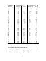
1
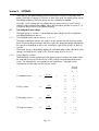
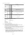
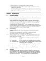
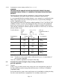
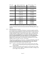
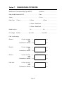
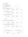
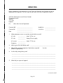
Service Manual
Type MCGG
Overcurrent Relays for Phase and Earth Faults
Service Manual
Type MCGG
Overcurrent Relays for Phase and Earth Faults
HANDLING OF ELECTRONIC EQUIPMENT
A person's normal movements can easily generate electrostatic potentials of several thousand volts.
Discharge of these voltages into semiconductor devices when handling electronic circuits can cause
serious damage, which often may not be immediately apparent but the reliability of the circuit will have
been reduced.
The electronic circuits of ALSTOM T&D Protection & Control Ltd products are completely safe from
electrostatic discharge when housed in the case. Do not expose them to the risk of damage by
withdrawing modules unnecessarily.
Each module incorporates the highest practicable protection for its semiconductor devices. However, if it
becomes necessary to withdraw a module, the following precautions should be taken to preserve the high
reliability and long life for which the equipment has been designed and manufactured.
1. Before removing a module, ensure that you are at the same electrostatic potential as the equipment
by touching the case.
2. Handle the module by its front-plate, frame, or edges of the printed circuit board.
Avoid touching the electronic components, printed circuit track or connectors.
3. Do not pass the module to any person without first ensuring that you are both at the same
electrostatic potential. Shaking hands achieves equipotential.
4. Place the module on an antistatic surface, or on a conducting surface which is at the same
potential as yourself.
5. Store or transport the module in a conductive bag.
More information on safe working procedures for all electronic equipment can be found in BS5783 and
IEC 60147-0F.
If you are making measurements on the internal electronic circuitry of an equipment in service, it is
preferable that you are earthed to the case with a conductive wrist strap.
Wrist straps should have a resistance to ground between 500k – 10M ohms. If a wrist strap is not
available, you should maintain regular contact with the case to prevent the build up of static.
Instrumentation which may be used for making measurements should be earthed to the case whenever
possible.
ALSTOM T&D Protection & Control Ltd strongly recommends that detailed investigations on the electronic
circuitry, or modification work, should be carried out in a Special Handling Area such as described in
BS5783 or IEC 60147-0F.
TYPES:
MCGG22
MCGG42*
MCGG52*
MCGG53
MCGG62*
MCGG63
MCGG82*
CONTENTS
SAFETY SECTION
5
1.
DESCRIPTION
9
2.
2.1
SETTINGS
Time delayed element settings
10
10
3.
3.1
3.2
3.3
3.4
INSTALLATION
General considerations
Relay mounting
Unpacking
Storage
13
13
13
13
14
4.
4.1
4.2
4.3
COMMISSIONING
Commissioning preliminaries
Instructions for commissioning the relay on any setting or curve
Instructions for commissioning the relay at settings calculated for a
particular application
14
14
16
5.
5.1
MAINTENANCE
Power supply healthy test
22
22
6.
6.1
6.2
PROBLEM ANALYSIS
General
Procedure
23
23
23
7.
COMMISSIONING TEST RECORD
27
REPAIR FORM
29
Page 4
18
SAFETY SECTION
This Safety Section should be read before commencing any work on the equipment.
Health and safety
The information in the Safety Section of the product documentation is intended to
ensure that products are properly installed and handled in order to maintain them in
a safe condition. It is assumed that everyone who will be associated with the
equipment will be familiar with the contents of the Safety Section.
Explanation of symbols and labels
The meaning of symbols and labels which may be used on the equipment or in the
product documentation, is given below.
Caution: refer to product documentation
Caution: risk of electric shock
Protective/safety *earth terminal
Functional *earth terminal.
Note: this symbol may also be used for a protective/
safety earth terminal if that terminal is part of a
terminal block or sub-assembly eg. power supply.
*Note: The term earth used throughout the product documentation is the direct
equivalent of the North American term ground.
Installing, Commissioning and Servicing
Equipment connections
Personnel undertaking installation, commissioning or servicing work on this
equipment should be aware of the correct working procedures to ensure safety.
The product documentation should be consulted before installing, commissioning or
servicing the equipment.
Terminals exposed during installation, commissioning and maintenance may present
a hazardous voltage unless the equipment is electrically isolated.
If there is unlocked access to the rear of the equipment, care should be taken by all
personnel to avoid electric shock or energy hazards.
Voltage and current connections should be made using insulated crimp terminations
to ensure that terminal block insulation requirements are maintained for safety. To
ensure that wires are correctly terminated, the correct crimp terminal and tool for the
wire size should be used.
Page 5
Before energising the equipment it must be earthed using the protective earth
terminal, or the appropriate termination of the supply plug in the case of plug
connected equipment. Omitting or disconnecting the equipment earth may cause a
safety hazard.
The recommended minimum earth wire size is 2.5 mm2, unless otherwise stated in
the technical data section of the product documentation.
Before energising the equipment, the following should be checked:
Voltage rating and polarity;
CT circuit rating and integrity of connections;
Protective fuse rating;
Integrity of earth connection (where applicable)
Equipment operating conditions
The equipment should be operated within the specified electrical and environmental
limits.
Current transformer circuits
Do not open the secondary circuit of a live CT since the high voltage produced
may be lethal to personnel and could damage insulation.
External resistors
Where external resistors are fitted to relays, these may present a risk of electric shock
or burns, if touched.
Battery replacement
Where internal batteries are fitted they should be replaced with the recommended
type and be installed with the correct polarity, to avoid possible damage to the
equipment.
Insulation and dielectric strength testing
Insulation testing may leave capacitors charged up to a hazardous voltage. At the
end of each part of the test, the voltage should be gradually reduced to zero, to
discharge capacitors, before the test leads are disconnected.
Insertion of modules and pcb cards
These must not be inserted into or withdrawn from equipment whilst it is energised,
since this may result in damage.
Fibre optic communication
Where fibre optic communication devices are fitted, these should not be viewed
directly. Optical power meters should be used to determine the operation or signal
level of the device.
Page 6
Older Products
Electrical adjustments
Equipments which require direct physical adjustments to their operating mechanism to
change current or voltage settings, should have the electrical power removed before
making the change, to avoid any risk of electric shock.
Mechanical adjustments
The electrical power to the relay contacts should be removed before checking any
mechanical settings, to avoid any risk of electric shock.
Draw out case relays
Removal of the cover on equipment incorporating electromechanical operating
elements, may expose hazardous live parts such as relay contacts.
Insertion and withdrawal of extender cards
When using an extender card, this should not be inserted or withdrawn from the
equipment whilst it is energised. This is to avoid possible shock or damage hazards.
Hazardous live voltages may be accessible on the extender card.
Insertion and withdrawal of heavy current test plugs
When using a heavy current test plug, CT shorting links must be in place before
insertion or removal, to avoid potentially lethal voltages.
Decommissioning and Disposal
Decommissioning: The auxiliary supply circuit in the relay may include capacitors
across the supply or to earth. To avoid electric shock or energy
hazards, after completely isolating the supplies to the relay
(both poles of any dc supply), the capacitors should be safely
discharged via the external terminals prior to decommissioning.
Disposal:
It is recommended that incineration and disposal to water
courses is avoided. The product should be disposed of in a safe
manner. Any products containing batteries should have them
removed before disposal, taking precautions to avoid short
circuits. Particular regulations within the country of operation,
may apply to the disposal of lithium batteries.
Page 7
Technical Specifications
Protective fuse rating
The recommended maximum rating of the external protective fuse for this equipment
is 16A, Red Spot type or equivalent, unless otherwise stated in the technical data
section of the product documentation.
Insulation class: IEC 61010-1: 1990/A2: 1995
Class I
EN 61010-1: 1993/A2: 1995
Class I
This equipment requires a
protective (safety) earth
connection to ensure user
safety.
Installation
Category
(Overvoltage):
IEC 61010-1: 1990/A2: 1995
Category III
EN 61010-1: 1993/A2: 1995
Category III
Distribution level, fixed
installation. Equipment in
this category is qualification
tested at 5kV peak, 1.2/50µs,
500Ω, 0.5J, between all supply
circuits and earth and also
between independent circuits.
Environment:
IEC 61010-1: 1990/A2: 1995
Pollution degree 2
EN 61010-1: 1993/A2: 1995
Pollution degree 2
Compliance is demonstrated by
reference to generic safety
standards.
Product safety:
73/23/EEC
Compliance with the European
Commission Low Voltage
Directive.
EN 61010-1: 1993/A2: 1995
EN 60950: 1992/A11: 1997
Compliance is demonstrated
by reference to generic safety
standards.
Page 8
Section 1.
DESCRIPTION
The MCGG 22, 42, 52, 62 and 82 are single, two, three or four pole overcurrent
relays, with separate measuring boards for each phase or earth fault input.
The MCGG 53 and 63 are three pole versions, having their phase inputs combined
onto one measuring board.
Each pole of the relay provides a choice of four IDMT characteristics and three
definite time characteristics. Additionally, each pole is provided with an
instantaneous high-set element which can be disabled if not required.
The seven versions of the relay covered by this manual are as follows :
MCGG 22
Single phase with instantaneous element
MCGG 42* Two phase with instantaneous elements
MCGG 52* Two phase plus earth fault with instantaneous element
MCGG 53
Two phase (with polyphase measurement) plus earth fault with
instantaneous elements
MCGG 62* Three phase with instantaneous elements
MCGG 63
Three phase (with polyphase measurement) with instantaneous
element
MCGG 82* Three phase plus earth fault with instantaneous elements
The rated current of the relay (In) is either 1A or 5A and appears on the module
rating label.
The relay comprises a case and single plug-in module, which utilises either one or
two 28 way terminal blocks. The module is designed with ease of assembly and
maintenance in mind, with a switch mode dc-dc converter on a mother-board at the
back of the module. This board carries connectors so that printed circuit boards
carrying timing/measuring circuitry which can derive IDMT and definite time
characteristics can be plugged in.
* Refer to ALSTOM T&D Protection and Control Ltd for manual applicable to
MCGG 42, 52, 62 and 82 relays with the last four model number digits 0501,
0751 or 1001.
Page 9
Section 2.
SETTINGS
These settings are determined by positioning miniature switches on the relay front
panel. There are two groups of switches on each relay pole, the upper group sets the
time delayed element, the lower group sets the instantaneous element.
Normally, switch settings are only altered during commissioning. If switch setting
changes under load are unavoidable, follow the procedure outlined in Section 2.1.6
to minimise the possibility of accidental tripping.
2.1
Time delayed element settings
The upper group of switches is sub-divided into three sub-groups which enable the
time delayed element to be set.
2.1.1
Time delayed current setting switches, I = ∑ x In
The upper seven blue switches are used to set the required current sensitivity setting.
Each switch may be positioned to the left or right, the setting level being indicated at
the same horizontal level as the switch, to the left or right of the switches or bank of
switches.
The overall setting is obtained by adding the indicated values of the individual switch
settings, and may be set in steps of 5% over the range 0.05 to 2.4 x In.
2.1.2
Curve selection switches
The three black switches positioned in the upper group of switches are used to select
the required time curve from the choice of four inverse time and three definite time
curves. The characteristic curve equations are listed below. The eighth switch
combination sets the relay into the ‘trip test’ mode.
Switch
Position
0
SI Standard inverse
VI Very inverse
EI Extremely inverse
LTI Long time inverse
t=
t=
t=
t=
0.14
(I0.02 – 1)
13.5
(I – 1)
80
– 1)
(I2
120
(I – 1)
Page 10
s
s
s
s
1
0
0
<- - <- - -
0
<- - -
1
0
- - ->
<- - -
0
<- - -
0
1
<- - - - ->
0
<- - -
1
1
- - ->
- - ->
0
<- - -
Where I is the ratio of the applied current to the setting current Is.
D2 Definite time 2s
D4 Definite time 4s
D8 Definite time 8s
Trip test
Note:
2.1.3
0
<- - -
0
<- - -
1
- - ->
1
- - ->
0
<- - -
l
- - ->
0
<- - -
1
- - ->
1
- - ->
1
- - ->
1
- - ->
1
- - ->
It is recommended that visual indication of the curve selected is made by
marking the appropriate square(s) provided for each (use the pegs provided
on earlier relays).
Time multiplier setting switches x t = ∑
Six blue switches positioned at the bottom of the upper switch group are used to set
the required time multiplier. The time given by each of the time delayed operating
characteristics must be multiplied by the time multiplier to give the actual operating
time of the relay pole. The setting is obtained by adding the indicated values of the
individual switch settings and is indicated by
x t = ∑.
Note:
2.1.4
Although it is possible to set the switches to give a TMS of 0.025x t, this
setting cannot be guaranteed to give specified accuracy. Therefore only
settings in the range 0.05 to 1.0 x t should be used.
Instantaneous element setting Iinst = ∑ x Is
The lower separate group of six blue slider switches is used to select the required
instantaneous current settings between 1 x Is and 31 x Is. The selected setting is
obtained by adding the indicated values of the individual switch settings. This value
multiplied by the time delayed current setting gives the operating current of the
instantaneous element.
If the instantaneous element on the relay pole is not required, then the switches
should all be set to the left (indicating zeros), or the bottom switch should be set to
the right (indicating infinity).
Page 11
2.1.5
Relay setting example
In this case:–
Current
setting
switches
0.1
0.1
0.2
0.4
0.4
0.4
0.8
<- <- <- - ->
- ->
- ->
<- -
0.05
Is
0
0
0
Is = ∑ x In
0
0
0
Curve
select
switches
0
0
0
<- <- <- -
1
1
1
TMS
switches
0.025
0
0
0
0
0
- ->
- ->
<- <- <- - ->
0.05
0.05
0.1
0.2
xt=∑
0.2
0.4
0
0
0
0
0
0
<- - ->
<- - ->
<- <- -
1
2
4
8
16
∞
Instantaneous
current
setting
switches
= (0.1 + 0.1 + 0.2 + 0.8) x In
= 1.2 x In
Standard inverse curve
TMS = (0.05 + 0.05 + 0.4)x
= 0.5x
Iinst = (8 + 2) x Is
Iinst = ∑ x Is
= 10 x 1.2 x In
= 12 x In
If the above settings were applied to a 1A relay
Current setting
= 1.2A
Curve
= Standard Inverse
TMS
= 0.5 x
Instantaneous
current setting
= 12A
(Currents are secondary values.)
2.1.6
Procedure for resetting the MCGG DIL switches in service
Normally settings are changed with the ac input and/or the dc auxiliary supply
disconnected during commissioning at the required setting.
If either the current setting (Is) or the highset threshhold setting (Iinst) has to be altered
in service then, to minimise the likelihood of any resultant tripping, the following
procedure should be adopted:
1. Temporarily disable the highset element by moving the Iinst 0/∞ switch from the
left (0) to the right (infinity) position.
2. Increase the Is current setting to the maximum by moving all Is switches to left
hand positions. Set the new setting current by moving to the right the switches
required to achieve the new setting. This ensures that an intermediate Is value
lower than the load current is not accidentally applied, resulting in operation of
either the highset or the IDMT element.
Page 12
3. Move the highset (Iinst) switches to the new setting required.
4. Re-enable the highset element by moving the Iinst 0/∞ switch from the infinity
(right) to the 0 (left) position.
Note that the TMS switches and the black curve select switches can be moved at
any time when the load current is less than the setting current (ie. when the green
LED is off) without affecting operation.
Section 3.
3.1
INSTALLATION
General considerations
Protective relays, although generally of robust construction, require careful treatment
prior to installation on site. Upon receipt, relays should be examined immediately, to
ensure no damage has been sustained in transit.
When handling a relay, great care must be taken, particularly when the relay is
removed from its case. Touching the printed circuit board should be avoided, since
metal oxide semiconductor (MOS) devices are used, which can be damaged by
static electricity discharges from the body.
If damage has been sustained in transit, a claim should be made to the transport
contractors and ALSTOM T&D Protection and Control Ltd should be promptly notified.
Relays which are supplied unmounted and not intended for immediate installation
should be returned to their protective polythene bags.
3.2
Relay mounting
Relays are despatched either individually or as part of a panel/rack mounted
assembly.
If the relays are to be installed into a panel/rack assembly after receipt,
then construction details can be found in Publication R7012.
3.2.1
When the MCGG is used in conjunction with other ALSTOM T&D Protection and
Control Ltd relays, the following guidelines should be followed for positioning the
relays in the modular assembly :
(1) Test facilities:
MMLG test block should be positioned at the right of
the tier.
(2) Current relays:
MCGG overcurrent relay should be adjacent to test block.
(3) Directional control:
METI directional relay should be adjacent to, and to the left
of the MCGG relay it is controlling.
(4) Other relays:
Any other relays required for the relay scheme, should be
positioned to the left of the tier viewed from the front.
3.2.2
For individually mounted relays, an outline diagram is normally supplied
showing panel cut-outs and hole centres, these dimensions will also be found
in Publication R6054.
3.3
Unpacking
Care must be taken when unpacking and installing the relays so that none of the
parts is damaged or their settings altered and they must at all times be handled by
skilled persons only. The installation should be clean, dry and reasonably free from
dust and excessive vibration. The site should be well lit to facilitate inspection.
Page 13
Relays which have been removed from their cases should not be left in situations
where they are exposed to dust or damp. This particularly applies to installations
which are being carried out at the same time as constructional work.
3.4
Storage
If relays are not installed immediately upon receipt they should be stored in a place
free from dust and moisture in their original cartons and where de-humidifier bags
have been included in the packing they should be retained. The action of the
de-humidifier crystals will be impaired if the bag has been exposed to ambient
conditions and may be restored by gently heating the bag for about an hour, prior to
replacing it in the carton.
Dust which collects on a carton may, on subsequent unpacking, find its way into the
relay; in damp conditions the carton and packing may become impregnated with
moisture and the de-humidifying agent will lose its efficiency.
Storage temperature –25° to +70°C.
Section 4.
COMMISSIONING
4.1
Commissioning preliminaries
4.1.1
Inspection
Carefully examine the module and case to see that no damage has occurred since
installation and visually check that any current transformer shorting switches are
wired into the correct circuit and are closed with the module withdrawn.
Check that the relay serial number on the module, case and cover are identical
and that the model number or rating information is correct.
4.1.2
Wiring
Check that the external wiring is correct to the relevant relay diagram or scheme
diagram. The relay diagram number appears inside the case.
4.1.3
Insulation
Isolate all wiring from earth and test the insulation of the external wiring with an
electronic or brushless insulation tester at dc voltage not exceeding 1000V. Terminals
of the same circuit should be temporarily strapped together.
The directional control circuits are isolated from all other circuits but are electrically
connected to the relay case. These circuits must not therefore, be insulation or impulse
tested to the case.
4.1.4
Electrostatic discharges (ESD)
The relay uses components which are sensitive to electrostatic discharges.
When handling the module, care should be taken to avoid contact with components
and electrical connections. When removed from the case for storage, the module
should be placed in an electrically conducting anti-static bag.
See full recommendations inside front cover.
4.1.5
Earthing
Ensure that the case earthing connection above the rear terminal block is used to
connect the relay to a local earth bar.
Page 14
4.1.6
Main current transformers
DO NOT OPEN THE SECONDARY CIRCUIT OF A LIVE CT SINCE THE HIGH
VOLTAGE PRODUCED MAY BE LETHAL TO PERSONNEL AND COULD DAMAGE
INSULATION.
4.1.7
Test block type MMLG
If test block type MMLG is provided, the connections should be checked to the
scheme diagram, particularly that the supply connections are to the ‘live’ side of the
test block (coloured orange) and with terminals allocated with odd numbers (1, 3, 5,
7 etc.) and also that the dc connection is routed via test block terminals 13 and 15.
4.1.8
Terminal allocation
Reference should be made to the diagram supplied with every relay.
4.1.9
Test equipment required:
Overcurrent test set with timing facilities
Multifinger test plug type MMLB 01 for use with test block type MMLG when required
Calibrated multimeter 0 – 10A ac 0 – 250V dc
4.1.10
General
Secondary injection commissioning tests should be carried out using a portable single
phase overcurrent test equipment, preferably injected via test block type MMLG. It is
most important that the test equipment is capable of injecting an undistorted
sinusoidal current waveform.
4.1.11
DC supply
Remove the relay module from its case. The incoming supply should be checked at
the relay case terminals. Relay case terminal 13 should be positive with respect to
terminal 14 and the incoming voltage must be within the operative range specified
below.
DC rating (V)
Operative range (V)
24/54
48/125
110/250
19 – 60
37.5 – 150
87.5 – 300
CAUTION: The relay is designed to withstand an ac ripple component of up to
±12% of the nominal dc auxiliary supply voltage. However, in all cases
the peak value of the dc supply must not exceed the maximum specified
operating limit.
Operation of the supply battery charger with the batteries disconnected could cause
damage due to overvoltage.
4.1.12
Relay CT shorting switches
With the relay removed from its case, check that each CT shorting switch is closed by
injecting rated current into each phase circuit. The rated current of the relay (In) is
either 1A or 5A and appears on the module rating label.
Page 15
4.1.13
Energise relay
For secondary injection testing using test block type MMLG, insert test plug type
MMLB 01 with the required main CT shorting links fitted. It may then be necessary to
link across the front of the test plug to restore the dc supply to the relay.
Isolate the relay trip contacts and insert the module. Ensure that the curve selection
switches on each pole are set to any position except 111. Connect the dc supply to
the relay. The relay has a non-volatile memory which remembers the state (ON or
OFF) of the LED trip indicators when the relay was last powered, and therefore some
or all of the indicators may be illuminated.
Press the RESET button and check that the LEDs on all of the poles are illuminated.
Release the RESET button and check that the LEDs reset.
Note:
To commission the relay with the settings and curve required for the
particular application, omit Section 4.2 and proceed directly to Section 4.3.
If the settings/curve will be altered by the user without re-commissioning the
relay, complete the tests in both Sections 4.2 and 4.3.
4.2
Instructions for commissioning the relay on any setting or curve
4.2.1
Current sensitivity switches (Is = ∑ x In)
This test checks that each of the front panel current selector switches operates
correctly. The green relay start LED provided on the front panel gives indication when
the input current exceeds the setting current Is.
Inject single phase current into a phase circuit and slowly increase the current until
the start LED lights. Repeat the test for each switch in turn and check that the pick up
current is within the range shown in Table 4.1
Switch selections:
Current
Curve
TMS
Instantaneous
(Is = ∑ x In)
)
(
(x t = ∑)
(Iinst = ∑ x Is)
Is
( x In)
AC current operate level (amps)
In = 1A
In = 5A
0.05
0.10
0.15
0.25
0.45
0.45
0.45
0.85
0.05
0.10
0.15
0.25
0.45
0.45
0.45
0.85
- 0.055
- 0.110
- 0.165
- 0.275
- 0.495
- 0.495
- 0.495
- 0.935
0.25
0.50
0.75
1.25
2.25
2.25
2.25
4.25
-
:
:
:
:
as shown
any
any
any
0.275
0.550
0.825
1.375
2.475
2.475
2.475
4.675
Table 4.1
Note:
1. The above current levels make no allowance for errors in measurement of
the ac current amplitude
2. The reference range for MCGG 22, 42, 52, 62 and 82 relays is 0.05In
to 2.4In
3. The reference range for MCGG 53, 63 relays is 0.2In to 2.4In
These tests should be repeated for each pole of the relay.
Page 16
4.2.2
Curve selection switches (
)
Connect the relay time delayed output contacts to both trip the test set, and to stop
a timer. Inject single phase current into the pole under test at a current level of 10 x
rated current.
Check that the operating time for the relay for each curve setting is within the range
shown in Table 4.2.
Switch selections:
Current
Curve
TMS
Instantaneous
Selected curve
SI
VI
EI
LTI
D2
D4
D8
(Is = ∑ x In)
(
)
(x t = ∑)
(Iinst = ∑ x Is)
:
:
:
:
1 x In
as shown
1xt
∞
Operating time range at 10 x Is (seconds)
Nominal
Range
Standard inverse
Very inverse
Extremely inverse
Long time inverse
Definite time 2s
Definite time 4s
Definite time 8s
2.97
1.50
0.808
13.3
2.00
4.00
8.00
2.82
1.42
0.747
12.6
1.94
3.88
7.76
–
–
–
–
–
–
–
3.12
1.58
0.869
14.0
2.06
4.12
8.24
Table 4.2
Note:
The above operating time ranges make no allowance for errors in
measurement of the ac current amplitude.
These tests should be repeated for each pole of the relay.
4.2.3
Time multiplier setting switches (x t = ∑)
Connect relay time delayed output contacts to both trip the test set and to stop a
timer. Inject single phase current into the pole under test at a current level of 10 x
rated current.
Measure the operating time on the SI curve at the TMS switch positions shown in
Table 4.3.
Switch Selections: Current
Curve
TMS
Instantaneous
TMS value
0.125 x t
0.2 x t
0.9 x t
(Is = ∑ x In)
(
)
(x t = ∑)
(Iinst = ∑ x Is)
:
:
:
:
1 x In
SI standard inverse
as shown
∞
Operating time range at 10 x In (seconds)
Nominal
Range
0.371
0.594
2.67
0.322 – 0.42
0.534 – 0.654
2.48 – 2.87
Table 4.3
Note:
The above operating time ranges make no allowance for errors in
measurement of the ac current amplitude.
These tests should be repeated for each pole of the relay.
Page 17
4.2.4
Instantaneous current setting switches (Iinst = ∑ x Is)
WARNING
THE RELAY MAY BE DAMAGED BY APPLYING EXCESSIVE CURRENT FOR LONG
DURATIONS DURING TESTING. IT IS IMPORTANT TO FOLLOW THE INSTRUCTIONS
PRECISELY.
The following test checks that the instantaneous current switches are operative.
The instantaneous trip output contacts must be connected to trip the test set.
It is recommended that the time delay element is set to operate in 4s and that the time
delay output contacts are also wired to trip the test set, to prevent relay damage if
current is applied for too long.
The current level should be set and then suddenly applied; DO NOT INCREASE THE
CURRENT SLOWLY since this may damage the relay. The test must be repeated for
each of the switch positions shown in Table 4.4 initially at a higher current level to
check that the instantaneous element operates and then at a lower level, at which the
element should not trip.
Switch selections:
Instantaneous
value
Current
Curve
TMS
Instantaneous
(Is = ∑ x In)
(
)
(x t = ∑)
(Iinst = ∑ x Is)
:
:
:
:
Current level (A)
In = 5A
In = 1A
0.5 x In
D4 definite time 4s
1xt
as shown
Iinst response
1 x Is
0.55
0.50
2.75
2.5
Trip
No trip
2 x Is
1.05
0.95
5.25
4.75
Trip
No trip
4 x Is
2.1
1.9
10.5
9.5
Trip
No trip
8 x Is
4.2
3.8
21.0
19.0
Trip
No trip
16 x Is
8.4
7.6
42.0
38.0
Trip
No trip
Table 4.4
Note:
The above current ranges make no allowance for errors in measurement of
the ac current amplitude.
These tests should be repeated for each pole of the relay.
4.3
Instructions for commissioning the relay at settings calculated for a
particular application
4.3.1
General
If there is any possibility that the relay settings are to be changed during the life of
the relay without re-commissioning, then the instructions in Section 4.2 should be
completed initially.
Ensure that the main system current transformers are shorted before isolating the relay
from the current transformers in preparation for secondary injection tests.
Page 18
4.3.2
Relay CT shorting switches
If not previously checked, and with the relay module removed from its case, check
that each CT shorting switch is closed by injecting rated current into each phase
circuit. The rated current of the relay (In) is either 1A or 5A and appears on the
module rating label.
4.3.3
Energise relay
Connect the dc supply to the relay and record the dc voltage at terminals 13 (+ve)
and 14.
4.3.4
Trip test
Set the curve selection switches to 111 (test mode), on one pole of the relay.
Check that the LEDs associated with that pole of the relay flash at a frequency of
approximately once per second.
Press and hold the RESET button. The LEDs of the other poles of the relay should
illuminate continuously, whilst those of the pole under test should continue to flash.
After approximately 6 seconds, the time delayed and instantaneous output elements
associated with the pole under test should trip and at the same time, the LEDs should
then illuminate continuously on that pole.
Release the RESET button. The output elements should reset.
Change the curve selection switches from 111 (test mode) to 101 (4s definite time),
and repeat the test on the other poles of the relay.
4.3.5
Instantaneous current settings (Iinst = ∑ x Is)
WARNING
THE RELAY MAY BE DAMAGED BY APPLYING EXCESSIVE CURRENT FOR LONG
DURATIONS DURING TESTING. IT IS IMPORTANT TO FOLLOW THE INSTRUCTIONS
PRECISELY.
This test is to check that the instantaneous current level as set, is correct.
The instantaneous trip output contacts must be connected to trip the test set.
It is recommended that the time delay element is set to operate in 4s and that the time
delay output contacts are also connected to trip the test set, to prevent relay damage
if current is applied for too long.
The current level should be set and then suddenly applied; DO NOT INCREASE THE
CURRENT SLOWLY since this may damage the relay.
Two tests, shown in Table 4.5 below, are specified for the particular x Is setting
required for the application. Initially the higher current level should be applied to
check that the instantaneous element operates and then the lower current level should
be applied to check that no trip occurs.
Switch selections:
Current
Curve
TMS
Instantaneous
(Is = ∑ x In)
(
)
(x t = ∑)
(Iinst = ∑ x Is)
Page 19
:
:
:
:
0.5 x In
D4 definite time 4s
1xt
As specified for the application
Instantaneous
setting (x Is)
1
2
3
4
5
6
7
8
9
10
11
12
13
14
15
16
17
18
19
20
21
22
23
24
25
26
27
28
29
30
31
Current level (A), In = 1A
No trip Iinst
Trip Iinst
0.50
0.95
1.4
1.9
2.3
2.8
3.3
3.8
4.2
4.7
5.2
5.7
6.1
6.6
7.1
7.6
8.0
8.5
9.0
9.5
9.9
10.4
10.9
11.4
11.8
12.3
12.8
13.3
13.7
14.2
14.7
0.55
1.05
1.6
2.1
2.7
3.2
3.7
4.2
4.8
5.3
5.8
6.3
6.9
7.4
7.9
8.4
9.0
9.5
10.0
10.5
11.1
11.6
12.1
12.6
13.2
13.7
14.2
14.7
15.3
15.8
16.3
Current level (A), In = 5A
No trip Iinst
Trip Iinst
2.5
4.75
7.1
9.5
11.8
14.2
16.6
19
21
23
26
28
30
33
35
38
40
42
45
47
49
52
54
57
59
61
64
66
68
71
73
2.75
5.25
7.9
10.5
13.2
15.8
18.4
21
24
27
29
32
35
37
40
42
45
48
50
53
56
58
61
63
66
69
71
74
76
79
82
Table 4.5
Note:
The above current levels make no allowance for errors in measurement of the
ac current amplitude.
This test should be repeated for each pole of the relay.
4.3.6
Instantaneous element operating time
It is not recommended that the instantaneous element operating time is checked, due
to the possibility of damage to the relay. The tests of section 4.3.5 and the previous
works tests provide adequate assurance that the operating time is correct.
Page 20
4.3.7
Curve selection (
)
The following test checks the selected curve characteristic at specified points.
WARNING
THE TEST EQUIPMENTS THERMAL LIMIT MAY BE EXCEEDED IF THE LONG TIME
INVERSE CURVE IS SELECTED.
Connect the relay time delayed output contacts to both trip the test set, and to stop a
timer. Inject single phase current into a convenient phase of each separate time delay
element at the current levels specified below for the particular curve selection
specified for the application.
Check that the operating time for the relay is within the range shown in Table 4.6
below.
Table 4.6 details the inverse time operating time curves at 2 x, 5 x, 10 x and
20 x Is. It is recommended that results are recorded at 10 x followed by 2 x Is,
the others are listed in case they are specifically requested by the user.
Definite time characteristics should be checked at 2 x Is only.
Switch selections: Current
Curve
TMS
Instantaneous
Curve
2 x Is
Nom. Range
SI
VI
EI
LTI
D2
D4
D8
10.03
13.50
26.7
120
2.00
4.00
8.00
9.52 - 10.6
12.8 - 14.2
24.6 - 28.7
114 - 126
1.94 - 2.06
3.88 - 4.12
7.76 - 8.24
(Is = ∑ x In)
(
)
(x t = ∑)
(Iinst = ∑ x Is)
:
:
:
:
1 x In
As specified for the application
1xt
As specified for the application
Operating time at specified current (seconds)
5 x Is
10 x Is
Nom. Range
Nom. Range
Nom.
4.28
3.38
3.33
30.0
2.27
0.711
0.201
6.32
4.06 - 4.50
3.20 - 3.55
3.08 - 3.59
28.5 - 31.5
2.97
1.50
0.808
13.3
2.82 - 3.12
1.42 - 1.58
0.747 - 0.869
12.6 - 14.0
20 x Is
Range
2.15 - 2.38
0.675 - 0.746
0.170 - 0.231
6.00 - 6.64
Table 4.6
Note:
The above operating time ranges make no allowance for errors in
measurement of the ac current amplitude.
These tests should be repeated for each pole of the relay.
4.3.8
Current sensitivity setting (Is = ∑ x In)
This test checks the sensitivity of the relay at the selected setting. The green relay start
LED provided on the front panel gives indication when the input current exceeds the
setting current Is.
Switch selections: Current
Curve
TMS
Instantaneous
(Is = ∑ x In)
(
)
(x t = ∑)
(Iinst = ∑ x Is)
:
:
:
:
As specified for the application
As specified for the application
1xt
As specified for the application
Slowly increase the applied single phase current until the start LED lights.
The minimum value of current to cause the start LED to light should be recorded.
Page 21
This level should be greater than
1 x Is x In
and less than
1.1 x Is x In
Note:
These levels make no allowance for errors in measurement of the ac current
amplitude.
These tests should be repeated for each phase of the relay.
4.3.9
Operating time at final selected settings
The relay switches should be set to the specified settings and the operating time of the
time delay circuit (t) should be measured at 2 x Is.
The measured time should be within ±5% or 40ms of the value computed from the
previous time measured at 2 x Is (in test 4.3.8) multiplied by selected TMS settings.
Switch selection:
Current
Curve
TMS
Instantaneous
(Is = ∑ x In)
(
)
(x t = ∑)
(Iinst = ∑ x Is)
As specified for
the application
Repeat test 4.3.9 for each pole of the relay.
4.3.10
Final check
Carefully check that the LED indicators and relay output contacts are all operating
correctly and that with the relay front cover replaced, the reset button satisfactorily
operates/resets the LEDs.
If required, check that the relay output contacts trip the circuit breaker, connect the
relay through to the main CTs and remove the CT shorts.
Section 5.
MAINTENANCE
Periodic maintenance is not required; however, periodic inspection and test is
advisable. It is recommended that the power supply healthy test outlined below is
carried out at regular intervals.
5.1
Power supply healthy test
The availability of power to the measuring boards can be checked at any time
without removing the protection provided by the relay. This is done by pressing the
reset button on the front panel.
All LEDs should illuminate if the relay is performing satisfactorily. When the
pushbutton is released, all the LEDs should be extinguished.
Page 22
Section 6.
6.1
PROBLEM ANALYSIS
General
These instructions enable a fault to be located to sub-assembly level. Fault finding at
component level is not recommended.
The major reasons for this are as follows :
(1) Fault finding on printed circuit boards (pcbs) requires specialised knowledge and
equipment.
(2) Components used in manufacture are subjected to strict quality control procedures
and in certain cases selected for particular characteristics. Metal oxide
semiconductor (MOS) components are used which require very careful handling.
(3) Damage can be caused to printed circuit board track unless extreme care is used
in replacement of components.
(4) Replacement of certain components will require recalibration of the relay.
In the event of a faulty sub-assembly being found, it is recommended that the
relay is returned to ALSTOM T&D Protection and Control Ltd or sent to a
competent service centre for the work to be carried out. However, replacement
sub-assemblies can be made available from
ALSTOM T&D Protection and Control Ltd upon request, provided the relay model
number and serial number are quoted. Recalibration of the relay is not required after
the replacement of a sub-assembly.
Note:
6.2
Before fault finding on the relay is commenced, all external connections and
supplies to the relay should be checked to ensure that the fault lies within the
relay.
Procedure
The following tests should only be carried out under laboratory conditions, when a
faulty relay has been identified and removed from its case.
6.2.1
Gaining access to the relay internal circuitry
The method for removing the frontplate on the Series 2 MCGG varies according to
the date at which the relay was supplied.
The earliest types are identified by the presence of one pozidrive type screw in both
the top and bottom plate of the module towards the left-hand side, adjacent to the
frontplate.
To remove the frontplate on this type, firstly remove the plastic handle strips from the
module handles to expose the two screws which secure the relay frontplate to the
module. These are located to the right-hand side of each handle and are recessed so
that their heads lie flush with the relay frontplate. Remove these two screws, together
with the two pozidrive screws mentioned above to release the frontplate.
Later types are not fitted with the two pozidrive type screws fitted in the top and
bottom plate of the module.
To remove the frontplate on this type, firstly remove the plastic handle strips from the
module handles. Next, remove all the screws which secure the handles to the
frontplate.
With the handles removed, remove the two remaining screws to release the
frontplate.
Page 23
On all versions of the MCGG 22, remove the handle strips followed by the handle
securing screws. Finally, with the handles removed, unscrew the remaining two
screws to release the frontplate.
With the frontplate freed from the rest of the module, tension on the wires to the flag
reset switch should be avoided. If necessary, the switch can be unscrewed from the
frontplate.
The latest types utilize clip-in type moulded handles. The black frontplate securing
screws are of the pozidrive type and are directly accessible without removing the
handles. Removal of these screws will release the frontplate. On these types, the reset
switch is not attached to the frontplate.
The measuring/timing PCBs can now be accessed as required.
6.2.2
DC internal power supply check
This can easily be done by pressing the reset button on the front panel.
All LEDs should illuminate if all measuring boards are operating satisfactorily.
Upon releasing the push-button, all LEDs should be extinguished.
Note:
6.2.3
This test may be carried out at any time whilst the relay is in service without
affecting its ability to measure or trip.
Output relay trip test
Set the curve selection switches on each measuring board, in turn, to the ‘111’
position.
This should result in the three LEDs on that measuring board flashing at a rate of one
per second.
If the reset bushbutton is then held pressed for approximately six seconds, both output
relays associated with that measuring board should energise, the LEDs will stop
flashing and remain in the on state until the push button is released.
In this way each measuring board, the associated output relays and their changeover
contacts can each be checked individually without the need for any input current
being applied.
Output miniature relays are an integral part of the module’s mother board, so in the
event of such a unit failing, the whole relay should be returned to ALSTOM T&D
Protection and Control Ltd for repair.
Note:
6.2.4
During this test, current transformer measurement is inhibited.
AC input tests
If one or more poles of the relay are inoperative, the input transformer for that relay
should be tested. For this test a current source capable of delivering 2x rated current
to the relay, and an ac ammeter, are required. The current should be applied to each
current input of the relay in turn and the ammeter should be used to measure the
current flowing from the directional control terminals for that particular pole of the
relay. With 2x rated current applied to the relay input (2A or 10A) the current
measured at the directional control terminals should be 20mA ± 10%.
Page 24
Relay type
Apply 2x rated current
to terminals (2A or 10A)
Measure 20mA ± 10%
at terminals
MCGG22
27 and 28
23 and 24
MCGG42
21 and 22
25 and 26
49 and 50
45 and 46
MCGG52
21 and 22
25 and 26
27 and 28
49 and 50
45 and 46
43 and 44
MCGG53
21 and 22
27 and 28
49 and 50
43 and 44
MCGG62
21 and 22
23 and 24
25 and 26
49 and 50
47 and 48
45 and 46
MCGG63
21 and 22
49 and 50
MCGG82
21
23
25
27
49
47
45
43
and
and
and
and
22
24
26
28
and
and
and
and
50
48
46
44
If 20mA is not obtained at the directional control terminals, then firstly the relay
wiring must be checked, both at the module contact moulding and at the pcb
connectors. If these are sound, then the input transformer of the faulty pole must be
replaced.
6.2.5
Measuring/timing circuitry tests
In the event that one or more poles of the relay is found to be inoperative and the
power supply and input transformer have been proved to be working correctly, then
the measuring/timing pcb (ZJ0091 on earlier versions, ZJ0161 on later versions)
must be suspected. In order to establish that this pcb is faulty, a ‘known-good’ pcb
should be moved from another position in the module, and tested in the position
where the suspect pcb had failed to work. Section 6.2.1 describes how to gain
access to the measuring boards. The measuring boards to be interchanged should
gently be pulled out from the mother board. When the measuring boards are
replaced, care should be taken to ensure that their connecting pins are correctly
aligned with the rear socket. See notes 1 and 2 below.
If this pcb works satisfactorily in this position, it can be assumed that the suspect pcb
is faulty and should be replaced. If, however, this pcb does not work either, the
mother-board should be suspected necessitating that the whole relay should be
returned to ALSTOM T&D Protection and Control Ltd for repair.
Note 1: Under no circumstances should current be injected into any of the relay
inputs when the corresponding measuring/timing pcb has been removed
from the module.
Note 2: At least one of the measuring/timing pcbs must be located in the module
when the dc auxiliary supply is connected to the module or damage to the
power supply circuitry may result.
Page 25
Page 26
Section 7.
COMMISSIONING TEST RECORD
Multifunction Overcurrent Relay Type MCGG
Serial No ...................................
Relay Model Number MCGG ....................................
Date ..........................................
Station.....................................................................
Circuit .......................................
Relay Type
1 Phase ......................... 2 Phase ........................ 3 Phase ...........................
2 Phase + Earth Fault ............................................
3 Phase + Earth Fault ............................................
Rated current In
DC voltage
1A ............................... 5A .................................
24/54V ..................... 48/125V .................... 110/250V ...........................
Final switch settings
Phase A:
Phase B:
Phase C:
Earth fault:
Current sensitivity
curve
TMS
Instantaneous element
Is
x In
Iinst
x Is
Current sensitivity
curve
TMS
Instantaneous element
Is
x In
Iinst
x Is
Current sensitivity
curve
TMS
Instantaneous element
Is
x In
Iinst
x Is
Current sensitivity
curve
TMS
Instantaneous element
Is
x In
Iinst
x Is
Page 27
Test results
4.1.13
Energisation test
................................
4.3.2
Relay CT shorting switches
................................
4.3.3
DC supply voltage
................................
4.3.4
Trip test
................................
4.3.5
Current level to trip Iinst (A)
Phase A
Phase B
Phase C
E.F.
........................
.......................
........................
.......................
Current level NOT to trip Iinst (A)
4.3.7
Phase A
Phase B
Phase C
E.F.
........................
.......................
........................
.......................
Operating time on selected curve(s)
Curve ......................
4.3.8
Phase A
Phase B
Phase C
E.F.
........................
.......................
........................
.......................
10 x Is .......................
.......................
........................
.......................
2 x Is .......................
.......................
........................
.......................
Current sensitivity at selected setting Is (A)
Is ..................................
4.3.9
Phase A
Phase B
Phase C
E.F.
........................
.......................
........................
.......................
Phase B
Phase C
E.F.
.......................
........................
.......................
Operating time at final selected setting(s)
TMS .......................
Phase A
2 x Is ........................
_____________________________________
______________________________________
Commissioning Engineer
Customer Witness
_____________________________________
______________________________________
Date
Date
Page 28
REPAIR FORM
Please complete this form and return it to ALSTOM T&D Protection and Control Ltd with the
equipment to be repaired. This form may also be used in the case of application queries.
ALSTOM T&D Protection and Control Limited
St. Leonards Works
Stafford
ST17 4LX,
England
For:
After Sales Service Department
Customer Ref: ___________________________
Model No: __________________
Contract Ref:
___________________________
Serial No:
Date:
___________________________
1.
__________________
What parameters were in use at the time the fault occurred?
AC volts
_____________ Main VT/Test set
DC volts
_____________ Battery/Power supply
AC current
_____________ Main CT/Test set
Frequency
_____________
2.
Which type of test was being used? ____________________________________________
3.
Were all the external components fitted where required?
(Delete as appropriate.)
4.
List the relay settings being used
Yes/No
____________________________________________________________________________
____________________________________________________________________________
____________________________________________________________________________
5.
What did you expect to happen?
____________________________________________________________________________
____________________________________________________________________________
____________________________________________________________________________
____________________________________________________________________________
continued overleaf
✁
Page 29
6.
What did happen?
____________________________________________________________________________
____________________________________________________________________________
____________________________________________________________________________
____________________________________________________________________________
7.
8.
When did the fault occur?
Instant
Yes/No
Intermittent
Yes/No
Time delayed
Yes/No
(Delete as appropriate).
By how long?
___________
What indications if any did the relay show?
____________________________________________________________________________
____________________________________________________________________________
____________________________________________________________________________
9.
Was there any visual damage?
____________________________________________________________________________
____________________________________________________________________________
____________________________________________________________________________
10. Any other remarks which may be useful:
____________________________________________________________________________
____________________________________________________________________________
____________________________________________________________________________
______________________________________
Signature
_______________________________________
Title
______________________________________
Name (in capitals)
_______________________________________
Company name
✁
Page 30
Page 31
A L S T O M T & D P r o t e c t i o n & C o n t r o l L t d St Leonards Works, Stafford, ST17 4LX England
Tel: 44 (0) 1785 223251 Fax: 44 (0) 1785 212232 Email: [email protected] Internet: www.gecalsthomgpc.co.uk
©1998 ALSTOM T&D Protection & Control Ltd
Our policy is one of continuous product development and the right is reserved to supply equipment which may vary from that described.
Publication R8054J
Printed in England.