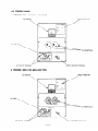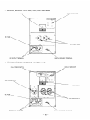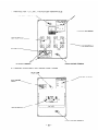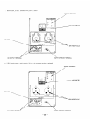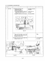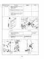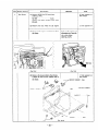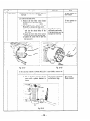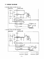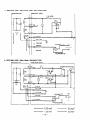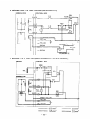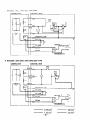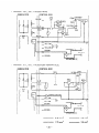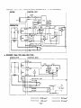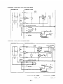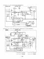
1
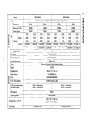
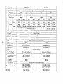
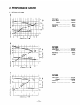
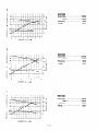
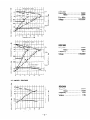
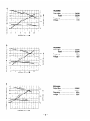
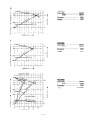
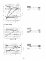
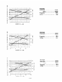
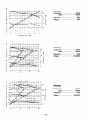
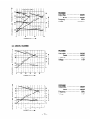
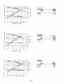
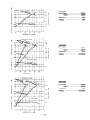
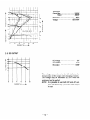
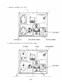
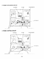
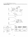
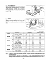
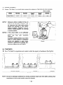
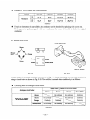
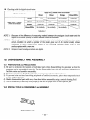
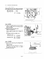
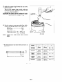
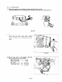
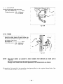
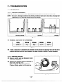
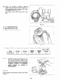
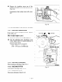
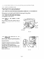
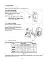
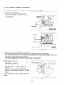
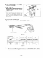
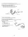
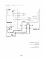
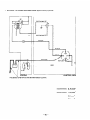
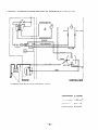
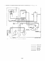
z&or
Model
RGXl80
RGX35OOlR
evised]
I--ISSUE EMD-GS0597B 1
CONTENTS
Section
Title
1. SPECIFICATIONS ....................................................................
2. PERFORMANCE CURVES
...............................................................
2-1
2-2
Model RGX1800
.......................................................................
Model RGX2400 .......................................................................
2-3
Model RGXCJ500.......................................................................
2-4
Model RGX5500 ......................................................................
2-5
DC OUTPUT ..........................................................................
3. FEATURES .................................................................................
4. GENERAL DESCRIPTION OF THE GENERATOR .................................
5.
1
3
3
5
8
11
14
15
16
4-1
External View of Generator
4-2
Control Panel .........................................................................
17
4-3
Location of Serial Number and Specification
31
32
CONSTRUCTION
..........................................................
Page
AND FUNCTION..
Number ..............................
..................................................
..........................................................................
5-1
5-2
Construction
5-3
Description of Generator Operation
Function ...............................................................................
16
32
32
.................................................
36
SAFETY PRECAUTIONS ................................................................
7. RANGE OF APPLICATIONS
............................................................
..........................................................
8. MEASURING PROCEDURES
Measuring Instruments ...............................................................
8-1
39
6.
8-2
8-3
AC Output Measuring
Measuring Insulation Resistance
9. CHECKING FUNCTIONAL
9-1
................................................................
Pilot lamp
....................................................
MEMBERS
...............................................
.............................................................................
......................................................................
40
43
43
46
46
48
48
48
9-2
AC Receptacles
9-3
Circuit Breaker ........................................................................
Stator ..................................................................................
49
49
50
9-6
Rotor ..................................................................................
Condenser ............................................................................
9-7
Diode Rectifier
9-4
9-5
10. DISASSEMBLY
........................................................................
AND ASSEMBLY
10-1 Preparation and Precautions
.....................................................
........................................................
10-3
Special Tools for Disassembly and Assembly .......................................
Disassembly Procedures ..............................................................
10-4
Assembly Procedures
10-5
Checking, Disassembly and Reassembly
10-2
................................................................
of the Control Box ......................
50
51
.52
52
52
53
61
68
Title
Page
Section
11. TROUBLE SHOOTING . . . . . . . . . . . . . . . . . . . . . . . . . . . . . . . . . . . . . . . . . . . . . . . . . . . . . . . . . . . . . . . . . . . 69
11-1
No AC Output . . . . . . . . . . . . . . . . . . . . . . . . . . . . . . . . . . . . . . . . . . . . . . . . . . . . . . . . . . . . . . . . . . . . . . . . 69
11-2
AC voltage is too high or too low . . . . . . . . . . . . . . . . . . . . . . . . . . . . . . . . . . . . . . . . . . . . . . . . . . . 71
11-3
11-4
AC voltage is normal at no-load, but the load cannot be applied. ......................... 72
73
No DC Output . . . . . . . . . . . . . . . . . . . . . . . . . . . . . . . . . . . . . . . . . . .
. . . . . . . . . . . . . . . . . . ..
11-5
Idle Control
. . . . . . . . . . . . . . . . . . . . . . . . . . . . . . . . . . . .... . . . . . . . . . . . . . . . . . . . . . . . . . . . . . . . . . . . 74
12. WIRING DIAGRAM
. . . . . . . . . . . . . . . . . . . . . . . . . . . . . . . ..................
77
RGXI 800
__-_--_. -.. .,__
----.,,.-.
Model
Type.
Brushless, Revolving Field, Self-Exciting,
--- ...-.
..---60Hz
--..--..,-.,_.
18OOW
..--.-. .,_-15oow
.- - ._.
Frequency
-.
.-_ _ -. ...-_.---Maximum Output
Rated Output
50Hz
-. --_--_
Rated
15oow
1300w
,--- -.
RGX2400
---
._._,__ _
---
13.6A
--,-.
12.5A
2-Pole, Single Phase
50Hz
.-
.--
2ooow
---._--....
17oow
.,
2400W
...--
2ooow
11ov
2;OV
.60Hz
-----.
- -- .._240V ‘.6.8A
-.-.- _--_
--I. ----. ,.Current
13.6Al6.8A
11 OVl22OV
._-.- .,
- --.-....._---_. .12OV/24OV
12.5Al6.3A
.-~
-- .i--..
.-_-..
. _--.
-._..._ . .._
-_---__A._.
--.. ._ .-1 .o
Power Factor
.--.
_ -~
_._..,,,,
,---_._,.
- . --._
.-_-.
..-._.._.
- -.-.--12V-8.3A (1 OOW)
DC Output
__--_.
,-_-__,...__
..- --_
,.,...--.
. __
-..
-,.
Condenser Type
Voltage Regulator
_..-..-_
..--..., .._~__
_,-,..
- ---.-.,-I-.,....- .Within 10%
Voltage Regulation
--.-.
..---_..__.
--.-._..-.-.....--._-.._,._
Robin Air-Cooled 4-Cycle Gasoline Engine
Type
-_
---_
..____
_. _.
EY20D
Model
--.
-..
. - _.___
--.----.-_- -., ... -_..--;83 cc (11.17 cu. in.)
Displacement
-_ . .,. _..-..-._.. .-.-..-.-.
3.5 HP13600 rpm
Rated Output
.- ..
_.-- ..,. .-. -_.,--. --.. -,-. ..-.-..__...---..Automobile Gasoline
Fuel
_-~_-..-..-.. . . _ - ...-.-.._.,.---_ .._
10 lit&s (2.64 U.S. gal.)
Fuel Tank Capacity
-.-_.
-. .._.----.
..-.- .-..
---_.
..-
-
Voltage
I
-L
I
Fuel Consumption Ratio
(at Rated Output)
._. .-- .
Oil Capacity
‘.,.. .. -, -__. ._.,-.,--Starting System
._. -.
- _._-.-.
--. .-,.., . ..--~.-.
.,._----.--
_
Dimensions L X W X H
-.._-._ _.. .._.
Drv Weight
.
. --
-_.------45 kg (97 Ibs.)
.- .-._--._- ..,.
600 cc
,_Recoil Starter
- ..-
552 X 377 X 482 mm
(21.7 X 14.8 X 19.0 in.)
---
..--
-.-. .45.5 kg (100 Ibs.)
Model
.-- ._,,--.-- .. _.___ --.
le
RGX5500
RGX3500
.._._
--.-
Brushless, Revolving Field, Self-Exciting, 2-Pole, Single Phase
- . ,..,..-_---._.
.____.
-.-----.-.-..-------.--...-- ._..
_.- -Frequency
50Hz
60Hz
50Hz
60Hz
--_.-,....- _...-_--_ ._.
--.
_,.._.
-.
-.-- -Maximum Output
3ooow
.-3500w
5ooow
5500w
-.-.-.--~..
____
-_---..---_
Rated Output
2500W
4400w
4800W
3ooow
._..--.. .,._, - -,,....--_
---- - .--.-...---.----_----1lOV
11ov
22.7A
1lOV
1lOV
43.6A
26.4A
40A
---------.--220v
11.4A
12ov
220v
12ov
40A
Rated
24.2A 20A
..---,--...--Voltage
240V
‘-220v
13.2A
240V
-. 18.3A
220v
21.8A
10.4A
-..-_-,-_._-_Current
11 OVi22OV 43.6A121.8A
11_OVl22OV
22.7Al11.4A
11 OVl22OV 26.4Al13.2A
11 OVI22OV
40Al20A
_.,
_-..
--.. -..
.- .-_
12OVI24OV
40Al20A
12OVl24OV 24.2Al12.1A
-’ . . .._-..- _--__-- __._,, .,
-.------.-,. .---. .Power Factor
1.0
--_ _._... __--_.. __.____-_.._.
. ,. . .~_______
-.-,.----..-_
DC Output
12V-8.3A
(1
OOW)
_._
..---...
._____
--.------.
-_-- --.
-.- ---,-.
Voltage Regulator
Condenser Type
~--.~
. _-.-_ -.-.- ._._-.---....--.-- .-.-.,-_ .__..-. ..-._--._.-Voltage Regulation
Within
10%
--,.,._- -.., .----.~--___
____--..,...-Robin
Air-Cooled 4-Cycle Gasoline Engine
Type
..-_-.____.
-._.
_
--._ .-__- _._----
I
N
I
Model
---.. ,,,.-Displacement
._..--.
. . .__--
Rated Output
. . .-._- .. .
__
Fuel
----- -,,._Fuel Tank Capacity
- .-.
Fuel Consumption
(at Rated Output)
,,
~
,._
-
-
Ratio
.-
--..--, _.--
----
------Automobile Gasoline
___
._-.-...
.. ..-.-
- .-..
.
85Occ
___
EY40D
..--.-._- -.-,.--388 cc (23.68 cu. in.)
------.
._-,8.0 HP/3600 rpm
-.,..-----
,-..--. .._-
_.--.15.5 liters (4.10 U.S. gal.)
--.-_--_-_---,--...---.---.---_---
-...-
-
50Hz: 2.7 liters/hour
60Hz: 3.1 liters/hour
-1200 cc
50Hz: 1.8 liters/hour
60Hz: 2.1 liters/hour
Lx W x H
-..
Dry Weight
--.-_
273 cc (l-6.66 cu. in.)
._ ..-...._5.5 HP/3600 rpm
____
--___
.--... .--~
-.---.13 liters (3.43 U.S. gal.)
..-..,.--
.._
- ,_.-.--,_
.--- -,.. -..-Oil Capacity
- ._
-.
-_ ,.
__Starting System
-... -- --___ -. _-.-.
Dimensions
EY28D
,,,. .-
. ._...-..
-- -.
-.-- .-. .-. .-_-----Recoil Starter and Optional Electric Starter
---.---..._....-..-.-~---.-----
552 X 413 X 520 mm
(21.7 X 16.3 X 20.5 in.)
.-_ ..-.
56 kg (123.5 Ibs.)
635 x 448 X 596 mm
(25.0 X 17.6 X 23.5 in.)
--_--
-_
76 kg (167,6 Ibs.)
2. PERFOMANCE
2-l
CURVES
MODEL RGX1800
t
RGXl800
Output Max. ......................
Rated .....................
JZpqueacy ........................
Voltage ...........................
0
2
4
6
8
10
12
15(-J(-jw
13oow
50Hz
ll()V
14
CURRENTIAI-
RGXI 800
Output Max. ......................
Rated .....................
Frequency ........................
Voltage ...........................
0
3
6
9
12
18OOW
15oow
60Hz
1lOV
15
CURRENTcAl-
RGXI 800
62
Output Max. ......................
Rated .....................
Frequency ........................
Voltage ...........................
60
0
I
3
.
.
6
Ii
/
9
,
I
12
I
1
15
CURRENT(A)-
-3-
18O()W
15oow
60Hz
12ov
RGXI 800
i
I
‘-1
Output Max. ......................
Rated .....................
Frequency ........................
Voltage ...........................
i
Llk
5
15oow
13o()w
C&Hz
22(Jv
0.5k 0’
t0
2
3
CURRENT
4
5
6
7
IA) +
RGXI 800
62
61
Output Max. ......................
Rated .....................
Frequency ........................
Voltage ...........................
2k
60
59
18()(-jW
15()ow
60Hz
22OV
240
2
5
Li.l..ll:lil,
0
j :
3
6
CURRENT
iAi
9
__)
RGXI 800
Output Max. ......................
Rated .....................
Frequency ........................
Voltage ...........................
0
1
2
CURRENT
3
4
5
6
7
IA1 __+
-4-
15o()w
13(-J()w
50Hz
24oV
I
52
RGXl800
x
I
z
51
2
u
49
;
240
Output Max. ......................
Rated .....................
Frequency ........................
Voltage ......................
50
3
110
:
100
a
k
d
,
0
2
4
6
CURRENT
6
10
12
14
IA)-
FREQUENCY
122OVt
62
7t
61
I
z
60
z
u!
59
i
a:
u.
15oow
13oow
50Hz
11 (y//22()v
RGX1800
2k
1.5k
t
4
Output Max. ......................
Rated .....................
Frequency ........................
Voltage ......................
180(34/
15oow
60Hz
11 ov/22ov
240
220
?
200
I
5_
120
bj
a
c
2
5
I
L0
110
100
0
3
6
CURRENT
9
12
15
IAl-
2-2 MODEL RGX2400
?
RGX2400
2k
t
t lk
0
4
6
12
CURRENT
(A)-
16
20
-5-
z
Output Max. ......................
Rated .....................
Frequency ........................
Voltage ...........................
2(-J)ow
17oow
50Hz
11ov
RGX2400
Output Max. ......................
Rated .....................
Frequency.. ......................
Voltage ...........................
/
I
E
2
!
II
0
1
s>
,
I
4
i..
!
i
i
i
8
c-ll!?RFh!T
11
12
i
I
I
1
24mw
2-Joow
60Hz
11(-g/
i
I
;
16
l
I
’
l
20
‘I
1
iA:-
RGX2400
Output Max. ......................
Rated .....................
Frequency.. ......................
Voltage ...........................
RGX2400
52
Output Max. ......................
Rated .....................
Frequency ........................
Voltage ...........................
51
50
49
240
220
200
j
!
0
2400~
2o(-Jow
60Hz
12ov
2
4
6
CURRENT
(A)-
a
’
(
10
-6-
24oow
2()oow
50Hz
22ov
RGX2400
Output Max. ......................
Rated .....................
Frequency.. ......................
Voltage ...........................
1 I ! i ’ I
I
I I
VOLTAGE
,
0
.g
5
1_
.
x
r
i:
z
w
3
0
Y
31
u.
t
I
I
2
I
.I
,
,
1
6
CURRENT
24oow
2()oow
60Hz
22ov
I
8
10
12
IA)-
RGX2400
52
Output Max. ......................
Rated .....................
Frequency ........................
Voltage ...........................
51
50
49
2o(-Jow
17oow
50Hz
24ov
260
240
5
u,
‘3
a
!I
220
2
0
2
4
6
CURRENT
I
I
I
I
FAE&JENCY
a
10
(A!-----)
I
i22OV!
52
1
2k
51
50
49
240 +
222
200
) +LT+E:,22+
0
4
8
CURRENT
12
(
)
16
20
(A) -
-7-
RGX2400
Output Max. ......................
Rated .....................
Frequency ........................
Voltage ......................
2ooow
17OOW
50Hz
11 (y//22(-y/
FREQUENCY
1
1220v)
*
1
I
0
.
12
e
4
CURRENT
2-3
MODEL
I
I
16
I
i
20
iAi __)
RGX3500
I
RGX3500
Output Ma.
-3k
2
w
c2
51
52
50
L
u
LL
49
110
1
10s
......................
Rated .....................
Frequency ........................
Voltage ...........................
t
C2K
z
c
2
k
2
0
-1k
120
t
Y
300Ow
25oow
50Hz
1lOV
-0
I
C
I
:
1
i
10
;
CURREilT
1
I
20
30
IA. __)
I II 1
4k
t
d
I
!II
(
3k
2k
1 lk
t
z
5
E
2
0
,
24()Ow
2-)(-jOw
fjo,-,z
l~()V~~OV
I
I
T
=
3
a
J
0
>
RGX2400
Output Max. ......................
Rated .....................
Frequency ........................
Voltage ......................
CURRENT
(At __t
-8-
RGX3500
Output Max. ......................
Rated .....................
Frequency ........................
Voltage ...........................
35oQw
3o()ow
60Hz
11ov
62
61
60
59
t
I
3
z
cl
6
I-
RGX3500
Output Max. ......................
Rated .....................
Frequency ........................
voltage ...........................
35(-j()w
3()o()w
fj0t-j~
12ov
RGX3500
Output Max. ......................
Rated .....................
Frequency ........................
Voltage ...........................
30@#
25oow
F&Hz
RGX3500
Output Max. ......................
Rated .....................
Frequency ........................
Voltage ...........................
3500w
30()@4/
6(-JHz
130
120
110
30
20
10
0
<
CURRENT
(Ale
t
I!!I!I!!!
I
-z
I
!!I!II
3k
52
51
2k
50
t
j
220v
s
49
i
2
240
220
200
8
4
0
>
CURRENT
I
T
63
z
v-
62+:
I i 11
!
I
I
,
:2
(A!-
4k
!
E:
CURRENT
(A\) d
-9-
220v
CURREIQT
i
0
i
I
,
1
62
-;=
61
7
v
u2
60
z
z
‘A
.I
I
I
20
10
III1
I
35(-Jaw
* .. 3oo()w
50Hz
11 ov/22(-jv
RGX3500
Output Max. ......................
Rated .....................
Frequency.. ......................
Voltage ......................
35oow
3o()()w
60Hz
11 ov/22ov
I
(Al-
240
220
10
CURREXT
RGX3500
Output Max. ......................
Rated ..................
Frequency ........................
Voltage ......................
30
59
0
3(yJ(-Jw
25oow
50Hz
24ov
(AI-
1
CURRENT
RGX3500
Output Max. ......................
Rated .....................
Frequency ........................
Voltage ...........................
20
30
IA,-
-
10 -
t
3
5
52
2
LL
62
61
60
59
RGX3500
3k
Output Max. ......................
Rated .....................
Frequency ........................
Voltage ......................
260
2k
240
f
4k
t
t
I
3
;:
3
35oow
3()o()w
60Hz
12ov/24ov
220
1
lk
I 0
30
CURRENT
2-4
MODEL
(A) +
RGX5500
RGX5500
5k
CURRENT
Output Max. ......................
Rated .....................
Frequency ........................
Voltage ...........................
5ooow
44OQW
50j.j~
11ov
(A\-
RGX5500
Output Max. ......................
Rated .....................
Frequency ........................
Voltage ...........................
62
61
60
59
I
i
’
’
;
120
110
100
CURREXT
iAld
-
11 -
55o()w
4@-Jow
60Hz
11ov
62
RGXSSOO
61
Output Max. ......................
Rated .....................
Frequency ........................
Voltage ...........................
60
59
i
1
,
5oo(-jw
48()@‘,/
60Hz
12ov
130
1
I lk
120
2
1’0
‘i
:I:;;
z
5
I
0
I
I
10
I
20
I.
30
CURRENT
(A;----)
I
40
I
I.
50
RGXSSOO
Output Max. ......................
Rated .....................
Frequency.. ......................
Voltage ...........................
0
5
10
15
CURRENT
(Al----)
20
5o(-Jow
44()()w
50Hz
22OV
25
RGXSSOO
Output Max. ......................
Rated .....................
Frequency
Voltage
‘2k
t lk
I
LO
)
0
5
10
CURREUT
15
1
(
23
I
I
(
1
I
1
z
5
0
’
25
IA!------)
- 12-
........................
...........................
55oow
48(-J&j/
60Hz
22ov
RGXSSOO
Output Max. ......................
Rated .....................
Frequency ........................
Voltage ...........................
5o()(y#
44oow
5(-~Hz
RGXSSOO
Output Max. ......................
Rated .....................
Frequency ........................
Voltage ......................
5OO()W
44(-J)w
50Hz
11 ov/22()v
RGXSSOO
Output Max. ......................
Rated .....................
Frequency ........................
Voltage ......................
55OOW
48()()W
fj(-)Hz
11 ov/22(y/
240V
I
0
I
?-
I
5
10
15
G
CURRENT
20
25
(A,-
52
1
51
Sk
so
49
-4k
t
240
-3k
2:
220
200
-2k
120
c lk
2
;r
3
2
2
110
100
0
10
20
30
CURRENT
(Al -
40
so
62
- 6k
61
t
60
- 5k
59
-4k
240
3k
t
I
2
;:
t
L
z
VOLTAGE
Zk
1220V1
I
lk
t
I
0
10
20
CURRENT
30
40
50
iAl ___)
-
13-
0
5
0
( 1 I ( I : ( [ ( 1 !
’
I
I
f?40Vi
FRFnl:Fk’rY
’
i
RGXSSOO
Output Max. ......................
Rated .....................
Frequency ........................
Voltage ......................
l 5k
55oow
48()&I,/
60Hz
12oVj24oV
L4n
i
‘3’<
0
2-5
20
30
CURRENT
(Al -
10
40
t
3
‘3
0
k
50
DC OUTPUT
DC
18
>
z
cl
14
dz
12
>
10
DC
16
Voltage
........................
Ampere
........................
DC output
........................
12~
8.3A
lO(yJ/
The voltage curve shown in the left indicates the
characteristic of DC output when charging a battery.
The voltage may be decreased by 20% when the
resistance load is applied.
NOTE:
CURRENT
(Al-
-
14 -
It is possible to use both DC and AC outputs simultaneously up to the rated output
in total.
3. FEATURES
3-1 BRUSHLESS
ALTERNATOR
Newly developed brushless alternator eliminates troublesome brush maintenance.
3-2 CONDENSER
TYPE VOLTAGE REGULATOR
A trouble free condenser type voltage regulator ensures a stable voltage under all working
conditions.
OIL SENSOR
3-3
Oil sensor automatically shuts off the engine whenever the oil level falls down below the lower limit
to protect the engine from seizure.
3-4 QUIET OPERATION
Robin RGX series generator delivers a quiet operation with :
A large super silent muffler.
A quiet 4-stroke Robin engine.
l A silent cyclone air cleaner.
l
l
3-5 NO RADIO NOISE
Noise suppressor spark plug and spark plug cap are equipped standard to prevent radio frequency
interference.
3-6 LARGE FUEL TANK
The large fuel tank allows more than 5 to 10 hours of continuous operation which is sufficient for a
half day or one day work without refueling.
3-7 RUGGED TUBULAR
FRAME
Full cradle type rugged tubuler frame protects the generator all around.
3-8 COMPACT AND LIGHT WEIGHT
Newly developed brushless alternator enabled the RGX generators to be very compact in size and
light in weight.
3-9 MINIMAL MAINTENANCE
l
l
l
l
l
l
A brushless alternator release the operator from periodical brush maintenance.
A trouble free condenser type voltage regulator.
A drip-proof alternator design.
No-fuse circuit breakers.
An electronic pointless ignition system.
A dust-proof cyclone air cleaner.
3-10 LONG-LIFE DURABILITY
The heav-duty 4 stroke Robin engine and virtually maintenance-free brushless alternator ensure
greater durability with :
l A brushless alternator with a condenser voltage regulator.
l Full rubber mount in a sturdy tubular frame.
l A forged steel crankshaft supported by two main ball bearings.
l A pointless electronic ignition system.
l A cast iron cylinder liner.
l A forged aluminum connecting rod.
-
15 -
4. GENERAL DESCRIPTION
OF THE GENERATOR
4-1 EXTERNAL VIEW of GENERATOR
NO FUSE BREAKER
(RGXl800.2400:
CIRCUIT
VOLTMETER
(PI LOT LAMP)
FULL POWER SWITCH
(DUAL VOLTAGE
TYPE)
IDLE CONTROL
(Option)
BREAKER)
/
/
SWITCH
CHOKE
/
I
/
LEVER
I .
/
,
AIR CLEANER
AC RECEPTACLE
3
DC FUSE
HOLDER
---I1
DC OUTPUT
RECOIL
STARTER
4
TERMINAL
1
EARTH
(GROUND)
FUEL
TERMINAL
C&K
TANK
PLUG
COVER
(SPARK
PLUG,
INSIDE1
MUFFLER
CAP
FUEL
GAUGE
/
.
FUEL
STOP
TANK
BUTTON
\
OIL SENSOR
(Option)
UNIT
DC FUSE
(RGX3500
OIL
FILLER
HOLDER
ONLY)
CAP-
/
OIL
DRAINING
DC OUTPUT
TERMINAL
(RGX3500
ONLY1
PLUG
-16-
4-2 CONTROL PANEL
l
RGXI 800 : SOHz-11 OV, 6OHz-120V TYPE
VOLTMETER
CIRCUIT
BREAKER
DC FUSE
-
\
DC OUTPUT
l
‘EARTH
TERMINAL
AC RECEPTACLE
(GROUND)
TERMINAL
RGX2400 : SOHz-11 OV, 60Hz-120V TYPE
CIRCUIT
VOLTMETER
+
BREAKER
AC RECEPTACLE
0
\
DC OUTPUT
EARTH
TERMINAL
-17-
(GROUND)
TERMINAL
l
RGX1800, RGX2400 : SOHz-220V, 24OV, 60Hz-220V TYPE
VOLTMETER
CIRCUIT
BREAKER
\
AC RECEPTACLE
A
DC OUTPUT
l
TERMINAL
EiRTH
(GROUND)
TERMINAL
RGXI 800, RGX2400 : SOHz, 60Hz-11 OV/22OV TYPE
POWER
FULL
SWITCH
CIRCU
IT BREAKER
)d
220V
RECEPTACLE
VOLTMETER
\
I
DC OUTPUT
A
-
11OV RECEPTACLE
\
TERMINAL
EARTH
- 18 -
‘GROUNDI
TERMINAL
l
RGXl800,2400
VOLTAGE
: U.K., SOHz-llOV/l20V
CHANGEOVER
[BS RECEPTACLE]
SWITCH
CIRCUIT
BREAKER
VOLTMETER
220V
RECEPTACLE
-
11OV RECEPTACLE
DC FUSE
DC OUTPUT
l
TERMINAL
EARTH
(GROUND)
TERMINAL
RGX2400 : U.S.A., 6OHz-120V [NEMA RECEPTACLE]
PILOT
LAMP
/CIRCUIT
BREAKER
(Option)
IDLE
coNTR\
120V
RECEPTACLE
I!
E
‘C
‘22
j
EAkTH
- 19 -
(GROUND)
TERMINAL
a RGXl800,2400
: GERMANY, SOHz-220V
CIRCUIT
BREAKER
;\
/’
C\
-nO=F
-l-l-
o
-------
u
VoLTMETER
I
DC
FusE\
DC OUTPUT
l
TERMINAL
RGX1800,2400
*C
52:.
/
A
EARTH
220V
(GROUND)
RECEPTACLE
TERMINAL
: SOHz-220V [WITH SPECIAL RECEPTACLE]
CIRCUIT
BREAKER
/
DC FUSE
+
220V
.
DC OUTPUT
EARTH
TERMINAL
- 20 -
(GROUND1
TERMINAL
RECEPTACLE
l
RGX1800,2400
: SWITZERLAND,
SOHz-220V
CIRCUIT
)
BREAKER
/
II
VOLTMETER
DC
FUSE\
DC OUTPUT
l
d22OV
TERMINAL
RGXl800,2400
: AUSTRALIA,
EARTH
RECEPTACLE
(GROUND)
TERMINAL
SOHz-240V
CIRCUIT
BREAKER
/
-
Dc
FusE\
/
VOLTMETER
I
AC
ii0:
+
240”
0
DC OUTPUT
EARTH
TERMINAL
- 21 -
(GROUND)
TERMINAL
RECEPTACLE
l
RGX3500 : SOHz-11 OV, 60Hz-12OV TYPE
START
(OptIon)
NO-FUSE
VOLTMETER
SWITCH
BREAKER
\
DC FUSE
/
AC RECEPTACLE
\
3
EARTH
l
(GROUND)
DC OUTPUT
TERMINAL
TERMINAL
RGX3500 : SOHz-220V, 24OV, 6OHz-220V TYPE
START
(OptIon)
NO-FUSE
VOLTMETER
SWITCH
BREAKER
\
DC FUSE
AC RECEPTACLE
\
EARTH
!GROUND)
DC OUTPUT
TERMINAL
- 22 -
TERMINAL
l
RGX3500 : 50Hz,60Hz-11
START
(Option)
OV/22OV TYPE
SWITCH
FULL
POWER
SWITCH
NO-FUSE
BREAKER
\
VOLTMETER
-
AC RECEPTACLE
A
0
EARTH
l
(GROUND)
TERMINAL
DC OUTPUT
TERMINAL
RGX3500 : U.K., 50Hz-1 lOV/22OV [BS RECEPTACLE]
START
(Option)
SWITCH
VOLTAGE
CHANGEOVER
SWITCH
*NO-FUSE
BREAKER
\
DC FUSE
VOLTMETER
220V
’
RECEPTACLE
)
11OV RECEPTACLE
/
0
\
EARTH
IGROUND)
- 23 -
TERMINAL
DC OUTPUT
TERMINAL
l
~Gx3500
START
(Option)
: U.S.A., 5oH~-120~/240v
[NEMA RECEPTACLE]
FULL
SWITCH
POWER
NO-FUSE
SWITCH
BREAKER
\
\
/
IDLE CONTROL
(Option)
240V
RECEPTACLE
-0
<O
12OV RECEPTACLE
EiRTH
l
TERMINAL
RGX35OO : GERMANY, 50Hz-220V
START
(Option)
NO-FUSE
VOLTMETER
SWITCH
BREAKER
I
\
22OV
(GROUND)
A
RECEPTACLE
/
EARTH
(GROUND)
DC OUTPUT
TERMINAL
- 24 -
TERMINAL
l
RGX3500 : 50Hz-220V
START
(Option)
WITH SPECIAL RECEPTACLE]
NO-FUSE
VOLTMETER
SW11
\
BREAKER
/
/
22OV RECEPTACLE
/
EARTH
l
(GROUND)
RGX3500 : SWITZERLAND,
START
(Option)
DC OUTPUT
TERMINAL
TERMINAL
50Hz-220V
NO-FUSE
VOLTMETER
SWITCH
\
BREAKER
I
C
220V
A
RECEPTACLE
/
/
,
)
,P
C
EARTH
(GROUND)
J
DC OUTPUT
TERMINAL
- 25 -
TERMINAL
DC
FUSE
RGX3500 : AUSTRALIA,
l
START
(Option)
50Hz-240V
VOLTMETER
SWI’ TCH
NO-FUSE
BREAKER
/
/
I
240V
RECEPTACLE
EARTH
l
DC
FUSE
(GROUND)
TERMINAL
DC OUTPUT
TERMINAL
RGX5500 : 50Hz-1 lOV, 60Hz-120V TYPE
VOLTMETER
DC FUSE
NO-FUSE
BREAKER
START
AC RECEPTACLF
EARTH
(GROUND)
TERMINAL
- 26 -
DC OUTPUT
TERMINAL
SWITCH
l
RGX5500 : 50Hz-220V, 24OV, 6OHz-220V TYPE
NO-FUSE
DC FUSE
VOLTMETER
BREAKER
/
START
SW.TCH
START
AC RECEPTACLE
l
k
EARTH
(GROUNDI
TERMINAL
DC OUTPUT
SWITCH
TERMINAL
RGX5500 : 50Hz, 6OHz-1 lOV/22OV TYPE
FULL
VOLTMETER
22OV
POWER
SWITCH
NO-FUSE
BREAKER
RECEPTACLE
/
\
DC FUSE
START
11OV RECEPTACLE
EARTH
(GROUND)
TERMINAL
- 27 -
DC OUTPUT
TERMINAL
SWITCH
l
RGX5500 : U.K., 50Hz-1 lOV122OV [BS RECEPTACLE]
VOLTMETER
11OV RECEPTACLE
VOLTAGE
CHANGEOVER
U
\f!-‘IS.=
NO-FUSE
SWITCH
9?:‘A.<i.?
BREAKER
DC FUSE
/
c f3artervchargec%“l
b//
220V
l
START
RECEPTACLE
RGX5500 : U.S.A., 6OHz-120V/240V
PILOT
240V
EARTH
(GROUND)
TERMINAL
DC OUTPUT
TERMINAL
SWITCH:
[NEMA RECEPTACLE]
FULL
LAMP
POWER
SWITCH
NO-FUSE
BREAKER
RECEPTACLE
\
IDLE
120V
RECEPTACLE
k
EARTH
iGROUND
TERMINAL
- 28 -
/
(opt’on)
1
START
CONTROL
SWITCH
l
RGX5500 : GERMANY, 50Hz-220V
VOLTMETER
NO-FUSE
DC FUSE
BREAKER
J
f
AC
223V
7
-
22OV RECEPTACLE
l
EARTH
(GROUND)
TERMINAL
START
DC OUTPUT
SWITCH
TERMINAL
RGX5500 : 50Hz-220V [WITH SPECIAL RECEPTACLE]
VOLTMETER
DC FUSE
NO-FUSE
BREAKER
START
22OV
RECEPTACLE
EARTH
(GROUND)
TERMINAL
DC OUTPUT
TERMINAL
SWITCH
l
RGX5500 : SWITZERLAND,
50Hz-220V
DC FI JSE
VOLTMETER
/
.
d
l.
22OV RECEPTACLE
l
RGX5500 : AUSTRALIA,
/
EARTH
!GROUND)
b
DC OUTPUT
TERMINAL
START
SWITCH
START
SWITCH
TERMINAL
50Hz-240V
DC FUSE
\
RECEPTACLE
BREAKER
\/
!I -
VOLTMETER
240V
NO-FUSE
I
EARTH
NO-FUSE
1
/
(GROUND!
TERMINAL
- 30 -
BREAKER
I
DC OdT
T TERMlhAL
4-3 LOCATION of SERIAL NUMBER and SPECIFICATION
NUMBER
Serial number and specification number are stamped on the LABEL (MODEL NAME) stuck on the end
cover.
NOTE: Always speciw these numbers when inquiring about the generator or ordering spare parts in
order to get correct parts and accurate service.
LABEL,
/
- 31 -
MODEL
NAME
5. CONSTRUCTION
AND FUNCTION
5-1 CONSTRUCTION
END
MOUNT
RUBBER
STATOR
COVER
BOLT
REAR
BALL
ROTOR
COVER
BEARING
THROUGH
STATOR
CO’vJPLETE
BOLT
SUPi’ORT
Fig. 5-1
5-2 FUNCTION
5-2-l
STATOR
The stator consists of a laminated silicon steel
sheet core, a main coil and a condenser coil which
are wound in the core slots.
The condenser coil excites the rotor field coil
which generates AC voltage in the main coil.
:
Fig. 5-2
-
32 -
RING
COMPLETE
\
FRbNT
COVER
5-2-2
CONDENSER
One or two condensers are installed in the control
box and are connected to the condenser coil of the
stator.
These condensers and condenser coil regulate the
output voltage.
I
I
J
Fig. 5-3
5-2-3
-
ROTOR
The rotor consists of a laminated silicon steel
sheet core and a field coil which is wound over the
core.
DC current in the field coil magnetizes the steel
sheet core. Two permanent magnets are provided
for the primary exciting action.
Fig. 5-4
A diode rectifier and surge absorber is mounted inside of the insulator.
Fig. 5-5B
Fig. 5-5A
- 33 -
5-2-4
I
FUSE
(1) The 10 ampere DC fuse mounted on the
control panel protects whole DC circuit from
getting damage by overload or short circuit.
;
i
Fig. 5-6
5-2-5
NO-FUSE BREAKER
The no-fuse breaker protects the generator from getting damage by overloading or short circuit in the
appliance.Table 5-l shows the capacity of no-fuse breaker by each spec. and their object of protection.
MODEL
I
7I
SPECIFICATION
llOV,
NO-FUSE
BREAKER
12A
120v
220v
RGXl800
240V
RGX2400
15A
Total output amperaae
8A
I
Total output amperage
240V
1
I
RGX3500
60Hz-11 OV/22OV, 12OVi24OV
10A
i
8A
(2 PCS.)
10A
(2 PCS.)
Total output amperage
22A
Total output amperage
25A
Total output amperage
50Hz-220V
12A
1
60Hz-220V
14A
10A
50Hz-11 OVl22OV
:
12A (PPole,
60HZ-11 OVl22OV. 12OVi24OV
,
14A (2-Pole, 2-Element)
llOV,
120v
I
Total output amperage
Total output amperage
I
2-Element)
Total output amperage
Total output amperage
!
Total output amperage
40A
Total output amperage
30A
Output from 30A receptacle
50Hz-220V
20A
I
Total output amperage
60Hz-220V
22A
I
Total output amrseraae
50Hz-240V
18A
I
~OHZ-1 1 OVi22OV
I
I
Total output amperage
1
50Hz-11 OV
I
1
Total output amperage
60HZ-11 ov, 12ov
50Hz-240V
RGX5500
Total output amperage
i
I
50Hz-11 OVl22OV
I
Total output amperage
5A
60Hz-220V
!
Total output amperage
6.3A (2 PCS.)
1lOV. 120v
50Hz-220V.
OBJECT of PROTECTION
Total output amperage
6.3A
11 OVi22OV, 12OVl24OV
I
I
60Hz-
!
20A (2-Pole. 2-Element)
30A
11 OV!22OV,
22A (2-Pole. 2-Element)
12OV,‘24OV
30A
Table 5- 7
-
34 -
Total output amperage
Total output amperage
Outwt
!
I
from 30A receotacle
Total output amperage
OUtDUt
from 30A receptacle
5-2-6
RECEPTACLE
and AC PLUG (STDSPEC.)
These are used for taking AC output power from the generator. A total of five kinds of receptacles, each
varying in rated voltage and current from another, are used. Each model has at least one receptacle to
deliver the rated generator output. As many AC plugs as the receptacles, each matching the
corresponding receptacle, are provided. Table 5-2 shows the rated current for each receptacle. Be careful
not to use the receptacles and AC plugs beyond the specified amperage limits to prevent burning.
g&z@
up to total 15 amperes
from two receptacles
up to 15 amperes
up to 20 amperes
up to 30 amperes
(See Caution.)
Table 5-2
Caution:
To connect the appliance to locking receptacle,
insert the plug into the receptacle and turn it
clockwise to lock.
Fig. 5-7
NOTE: If your generator has receptacles peculiar to your country, Table 5-2 does not apply.
NOTE:
The generator for U.S.A. market is equipped with NEMA standard receptacles shown in table
5-3. Use the proper plug for connecting appliance to the generator.
Ampere
Style
Receptacle
125V
20A
125Vl25OV
20A
i
1
AC plug
NEME
5-20R
NEME
5-20P
NEME
L14-20R
NEME
L14-20P
Description
GFCI
i (Ground Fault Circuit
I Interrupter)
/ Receptacle, duplex
1
i Locking Receptacle
I
!
125V
30A
i
j
NEME
L5-30
I
Table 5-3
- 35 -
NEME
L5-3OP
8
Locking Receptacle
5-3 DESCRIPTION
of GENERATOR
PERMANENT
FOR INITIAL
FIELD
OPERATION
MAGNET
EXCITATION
COIL
MAIN
I
COIL
i
APPLIANCE
SURGE
ABSORBER
/
-----A~
I
I
I
DIODE
CONDENSER
COIL
CONDENSER
----_----I
Fig. 5-8
5-3-l
GENERATION
of NO-LOAD VOLTAGE
(1) When the generator starts running, the permanent magnet built-in to the rotor generates 3 to 6V of
AC voltage in the main coil and condenser coil wound on the stator.
(2) As one or two condensers are connected to the condenser coil, the small voltage at the condenser
coil generates a minute current -3 which flows through the condenser coil. At this time, a small flux
is produced with which the magnetic force at the rotor’s magnetic pole is intensified.When this
magnetic force is intensified, the respective voltages in the main coil and condenser coil rise up.
As the current @ increases, the magnetic flux at the rotor’s magnetic pole increases further. Thus the
voltages at the main coil and condenser coil keep rising by repeating this process.
(3) As AC current flows through the condenser coil, the density of magnetic flux in the rotor changes.
This change of magnetic flux induces AC voltage in the field coil, and the diode rectifier in the field
coil circuit rectifies this AC voltage into DC. Thus a DC current 3 flows through the field coil and
magnetizes the rotor core to generate an output voltage in the main coil.
(4) When generator speed reaches 2700 to 2800 rpm (50Hz type) or 3000 to 3300 rpm (60Hz type), the
current in the condenser coil and field coil increases rapidly.
This acts to stabilize the output voltage of each coils. If generator speed further increases to the rated
value, the generator output voltage will reach to the rated value.
5-3-2
VOLTAGE FLUCTUATIONS
UNDER LOAD
When the output current g flows through the main coil to the appliance, a magnetic flux is produced and
serves to increase current ,@ in the condenser coil. When current .z increases, the density of magnetic
flux across the rotor core rises. As a result, the current flowing in the field coil increases and the
generator output voltage is prevented from decreasing.
- 36 -
5-3-3
FULL POWER SWITCH (Dual Voltage Type)
The full power switch is provided for the dual voltage type to take out the full rated power from one
receptacle in each voltage.
120124OV
r - - - : Ior 110122OV)
I
P i
I
Fig. 5-9
low
Fig. 5- 10
Rec. 1
120v
MC,
Switch
Position
LOWER VOLTAGE
RECEPTACLE
HIGHER VOLTAGE
RECEPTACLE
1lOV
or
12ov
Rated output
’ No output can be taken.
11 Ol22OV
or
120!24OV
Half of rated
output
Rated output
(1lOV)
Rec. 3
4
Table 5-4
Fig. 5-11
-
37 -
Two main coils are wound over stator core. Each main coil outputs half the rated power at the lower
voltage (11OV or 12OV). These main coils are wound to be in the same phase. The full power switch
reconnects these main coils in parallel or in series.
Fig. 5-9 shows a circuit diagram.When the full power switch is set for single lower voltage indication
(1lOV or 12OV), the switch position is as indicated by the lower solid line in the diagram. Fig. 5-10 is a
simplified representation of this circuit, showing the two main coils connected in parallel.In this case, the
higher voltage (220V or 240V) at Rec. 3 cannot be taken out. Rec. 2 for the lower voltage can output up
to the rated power (up to 30A if the rated current is over 30A), and Rec. 1 can output up to a total of 15A.
When the full power switch is set for double voltage indication (llOV/22OV or 12OV/24OV), the switch
position is as indicated by the upper dotted line in Fig. 5-9. Fig. 5-11 is a simplified representation of this
circuit, showing the two main coils connected in series. In this case, power can be taken simultaneously
from the receptacles for the both voltages. Rec. 3 for the higher voltage can output up to the rated power,
but Rec. 1 and Rec. 2 for the lower voltage can output only up to half the rated power each.
Table 5-4 is a summary of the above explanation. Select the proper output voltage by full power switch in
accordance with the appliance to be used.
5-3-4
VOLTAGE CHANGEOVER
SWITCH
The generator of 50Hz llOV/22OV dual voltage type for U.K. is provided with voltage changeover
switch instead of full power switch.
The output voltage is selected from 1lOV and 220V by turning this switch and both voltages cannot be
taken out simultaneously.
1lOV
RECEPTACLE
220v
RECEPTACLE
IO-l
I
YFB
Fig. 5-12
- 38 -
I
I
9
6. SAFETY PRECAUTIONS
1. Use extreme caution near fuel. A constant danger of explosion or fire exists.
Do not fill the fuel tank while the engine is running. Do not smoke or use opern flame near the fuel
tank. Be careful not to spill fuel when refueling. If spilt, wipe it and let dry before starting the engine.
2. Do not place inflammable materials near the generator.
Be careful not to put fuel, matches, gunpowder, oily cloth, straw, and any other inflammables near the
generator.
3. Do not operate the generator in a room,cave or tunnel. Always operate in a well-ventilated area.
Otherwise the engine may overheat and also, the poisonous carbon monoxide contained in the exhaust
gases will endanger human lives. Keep the generator at least 1 m (4 feet) away from structures or
facilities during use.
4. Operate the generator on a level surface.
If the generator is tilted or moved during use, there is a danger of fuel spillage and a chance that the
generator may tip over.
5. Do not operate with wet hands or in the rain.
Severe electric shock may occur. If the generator is wet by rain or snow, wipe it and thoroughly dry it
before starting.
Don’t pour water over the generator directly nor wash it with water.
If the generator is wet with water, the insulations will be adversely affected and may cause current
leakage and electric shock.
6. Do not connect the generator to the commercial power lines.
This may cause a short-circuit or damage to the generator.Use a transfer switch for connecting with
indoor wiring.
NOTE:
The parts numbers of the transfer switches and of the plastic box to store them are as
shown in Table 6-1.
Part No.
I
a’tY
Phase
Transfer Switch
1
1
15A
367-45605-08
Transfer Switch
1
1
30A
340-45606-08
Transfer Switch
1
1
60A
Plastic Box
1
1
30A
Plastic Box
1
1
60A
365-45604-08
367-43008-08
348-43009-08
)
Part Name
1
1
I
Allowable
Current
Table 6-1
7. Use a fuse of the correct capacity. (DC output)
If the generator rpm is increased excessively in the overload condition by using an over rated fuse, the
generator may be burnt.
CAUTION : If the fuse is burnt or the circuit breaker tripped off as a result of using an
electrical appliance,the
cause can be an overload or a short-circuit.
In such a case, stop
operation immediately and carefully check the electrical appliance and AC plugs for faulty
wiring.
- 39 -
7. RANGE OF APPLICATIONS
Generally, the power rating of an electrical appliance indicates the amount of work that can be done by
it.The electric power required for operating an electrical appliance is not always equal to the output
wattage of the appliance. The electrical appliances generally have a label showing their rated voltage,
frequency, and power consumption (input wattage). The power consumption of an electrical appliance is
the power necessary for using it.When using a generator for operating an electrical appliance,the power
factor and starting wattage must be taken into consideration.
In order to determine the right size generator, it is necessary to add the total wattage of all appliances to
be connected to the unit.
Refer to the followings to calculate the power consumption of each appliance or equipment by its type.
(1)
Incandescent
lamp, heater, etc. with a power factor of 1.0
Total power consumption must be equal to or less than the rated output of the generator.
Example:
A rated 3000W generator can turn thirty 1OOWincandescent lamps on.
(2)
Fluorescent
lamps,mercury
lamps, etc. with a smaller power factor
Select a generator with a rated output equivalent to 1.2 to 2 times of the power consumption of the
load.
Example:
A 400W mercury lamp requires 600W to 700W power source to be turned on.
A rated 3000W generator can power four or five 400W mercury lamps.
(3)
NOTEI:
If a power factor correction capacitor is not applied to the mercury lamp or fluorescent
lamp, the more power shall be required to drive those lamps.
A rated 3000W generator can drive one or two 400W mercury lamps without power factor
correction capacitors.
NOTE2:
Nominal wattage of the fluorscent lamp generally indicates the output wattage of the
lamp.
Therefore, if the fluorescent lamp has no special indication as to the power consumption,
efficiency should be taken into account as explained in Item (5) on the following page.
Motor driven tools and light electrical
appliances
Generally the starting wattage of motor driven tools and light electrical appliances are 1.2 to 3 times
lager than their running wattage.
Example:
A rated 25OW electric drill requires a 400W generator to start it.
(4)
Initially
loaded motor driven
appliances
such as water pumps,compressors,etc.
These appliances require large starting wattage which is 3 to 5 times of running wattage.
Example:
A rated 9OOW compressor requires a 45OOW generator to drive it.
NOTEl:
Motor-driven appliances require the aforementioned generator output only at the starting.
Once their motors are started, the appliances consume about 1.2 to 2 times their rated
power consumption so that the excess power generated by the generator can be used
for other electrical appliances.
NOTE;?:
Motor-driven appliances mentioned in Items (3) and (4) vary in their required motor
starting power depending on the kind of motor and start-up load. If it is ditficult to
determine the optimum generator capacity, select a generator with a larger capacity.
- 40 -
(5) Appliances
without
any indication
as to power consumption
Some appliances have no indication as to power consumption; but instead the work load (output) is
indicated. In such a case, power consumption is to be worked out according to the numerical formula
mentioned below.
(Output
of electrical
appliance)
= (Power
consumption)
(Efficiency)
Efficiencies of some electrical appliances are as follows:
Single-phase motor . * * . . . . a. . . - . . * . . 0.6 - 0.75
Three-phase motor . . - . . . . . . - - - * - . . 0.65 - 0.9 ItFluorescent lamp - - - * . . . . * . . . - ae. . . . 0.7 - 0.8
The smaller the motor, the
lower the efficiency.
Example 1: A 40W fluorescent lamp means that its luminous output is 40W. Its efficiency is 0.7 and
accordingly, power consumption will be 40 i 0.7= 57W. As explained in item(2), multiply
this power consumption value of 57W by 1.2 - 2 and you will get the figure of the necessary
capacity of a generator. In other words, a generator with a rated output of 1000Wcapacity
can light nine to fourteen 40W fluorescent lamps.
Example 2: Generally speaking, a 400W motor means that its work load is 400W. Efficiency of this
motor is 0.7 and power consumption will be 400 t 0.7= 57OW. When this motor is used for
a motor-driven tool, the capacity of the generator should be multipled by 1.2 to 3 and 570W
as explained in the Item(3).
MODEL
RGXl800
I
50Hz
’ 60Hz
Frequency
lncandesent lamp,
heater, etc.
Fluorescent lamp,
mercury lamp, etc.
j
Motor-driven tool,
general-purpose motor.
etc.
Water pump.
compressor, etc.
!
RGX2400
i
RGX3500
50Hz
60Hz
50Hz
60Hz
50Hz
3ooow
j 4400w
4800W
ZE
approx.
: 2800W
approx.
3200W
approx.
2600W
approx.
; 2900W
; approx.
1300w
approx.
1 1400w
13oow
15oow
17oow
2ooow
2500W
approx.
9oow
approx.
1ooow
approx.
11OOw
approx.
1300w
i approx.
; 17oow
approx.
800W
; approx.
/ 9OOW
I
! approx.
1OOOW
approx.
12oow
approx.
15oow
approx.
4oow
! approx.
450w
I
approx.
1 5oow
approx.
600W
approx.
750w
Table 7-1
-
RGX5500
41 -
approx.
18OOW
’ approx.
9oow
1
60Hz
NOTES:
Wiring between generator and electrical appliances
1. Allowable current of cable
Use a cable with an allowable current that is higher than the rated input current of the load
(electrical appliance). If the input current is higher than the allowable current of the cable used, the
cable wilt become excessively heated and deteriorate the insulation, possibly burning it out.
Table 7-2 shows cables and their allowable currents for your reference.
2. Cable length
If a long cable is used, a voltage drop occurs due to the increased resistance in the conductors
decreasing the input voltage to the load (electrical product). As a result, the load can be damaged.
Table 7-2 shows voltage drops per 100 meters of cable.
I
Nominal cross
sectlon
i Resistance
Amp.
I
mm2
I
No.
A
18
7
i
I
30/0.18
:
2.477
1.27
16
12
!
50:0.18
i
1.486
; 1.5v
2.0
14
:
17
37 i 0.26
0.952
I lV
; 3v
3.5
12-10
I
!
I
23
45!0.32
j
0.517
: -
j 1.5V 1 2.5V
] 4V
5.5
10-8
!
25
70:0.32
:’
0.332
/ -
( 1V (
!’ 2.5VI ’ 3.5Vi
0.75
I
Current
i
No. / mm
1
Q/iOOm
1A
3A j
2.5Vi8V
5A
12.5V
5v
! 7.5V
1 5v
2V
8A ] lOA
-
--I-
12V
15V
j 8V ; 1OV
12A
15A!
18V
-
12V i 15V
5V j 6.5V
7.5V
4V 1 5V i
Table 7-2
Voltage drop indicates as V = -&XRXIXe
R mens resistance ( 0 /lo0 m) on the above table.
I means electric current through the wire (A).
g means the length of the wire (m).
The length of wire indicates round length,it means twice the length from generator to electrical tools.
-
42 -
I
8. MEASURING
8-l MEASURING
8-l-l
PROCEDURES
INSTRUMENTS
“Dr. ROBIN” GENERATOR
TESTER
The “Dr. Robin”generator tester is exclusively
designed for fast, easy diagnosis and repair of
Robin generators.
The “Dr. Robin” has the following features:
(1) Functions of voltmeter, frequency meter,
meggertester, capacitance meter and circuit
tester are combined in one unit.
(2) Fast and easy readout by digital indicator.
(3) Built-in automatic battery checker indicates
the time to change batteries.
(4) Tester and accessories are installed in a
handy, sturdy case for easy carring.
l
!
I
’
’
L
Fig. 8-J
SPECIFICATIONS
Model
Dr. Robin
I
Part Number
388-47565-08
o-5ooV AC
Voltage
b
5
Frequency
E
::
Resistance
‘C
2 .
Condenser Capacity
9
zz
j Insulation Resistance
2%70Hz
I
0.1-l ,999 4
lo-100
fiF
3MR
Fuse
Circuit Protector
2 x 6F44P (006P) Dry Cell Battery
Power Source
Test leads with needle probes . . .l set
Accessories
Dimensions
Test leads with jack plugs . . . . . . 1 set
285 mmx200
i
(L X W X H)
I
Weight
mmxll0
mm
1.6kg
Table 8- 1
The “Dr. Robin”generator tester can be ordered from Robin generator distributors by the following part
number.
Dr. Robin Part Number : 388-47565-08
If you do not have a “Dr. Robin”generator tester,use the instruments described in the following section
for checking generator parts.
- 43 -
!
8-l -2 INSTRUMENTS
0)
I
I
VOLTMETER
AC voltmeter is necessary.The approximate
AC voltage ranges of the voltmeters to be
used for various types of generators are as
follows:
0 to 150V: Type with an output voltage of
110 or 120V
0 to 300V: Type with an output voltage of
220,230 or 240V
0 to 15OV, 0 to 330V: Dual voltage type
’
)
FOR
I
AC
Fig. 8-2
(2)
AMMETERS
AC ammeter is necessary. An AC ammeter
with a range that can be changed according to
the current rating of a given generator is most
desirable. (About lOA, 20A, 100A)
I
I
:
FOR
AC
i
Fig. 8-3
(3) FREQUENCY METER
Frequency range : About 45 to 65Hz
NOTE:
I
I
I
Be careful of the frequency meter’s
input voltage range.
-!
----
I
I
Fig. 8-4
-
44 -
(4) CIRCUIT TESTER
Used for measuring resistance, etc.
Fig. 8-5
(5) MEGGER TESTER
Used for measuring generator insulation
resistance.
Select one with testing voltage range of
r
5oov.
(6) TACHOMETER
There are various types of tachometers, such
as contactless type, contact type, and strobe
type. The contact type can be used only when
the generator and engine have been disassembled. The contactless type is recommended.
I
’
1
1
I
CONTACTLESS
TYPE
I
1
;
I
I
I
STROEk
Fig. 8-7
- 45 -
TYPE
8-2 AC OUTPUT MEASURING
Fig. 8-8
Use a circuit like the shown in Fig.E-8 for measuring AC output. A hot plate or lamp with a power factor
of 1.0 may be used as a load. Adjust the load and rpm. and check that the voltage range is as specified in
Table 8-2 at the rated amperage and rated rpm.
I
Rated voltage
1
Voltage range
12ov
11ov
220v
117-l 3ov
107-119v
215238V
240V
235-2aov
Table 8-2
8-3 MEASURING
INSULATION
RESISTANCE
Use a “Dr. RobirPgenerator tester in megger tester
mode or use a megger tester to check the
insulation resistance. Connect a megger tester to
one of receptacle output terminals and the ground
terminal, then measure the insulation resistance.
An insulation resistance of 1 megohm or more is
normal. (The original insulation resistance at the
time of shipment from the factory is 10 megohm
or more.)
If it is less than 1 megohm, disassemble the
generator and measure the insulation resistance of
the stator, rotor and control panel individually.
Fig. 8-9
l
STATOR
Measure the insulation resistance
(1)BLUE
lead and the core.
the insulation resistance
(2)Measure
WHITE lead and the core.
Measure the insulation resistance
(3)YELLOW
lead and the core.
Measure the insulation resistance
(4)BROWN
lead and the core.
between
between
between
between
I
I
I
Fig. 8-10
-
46 -
l
ROTOR
Measure the insulation across one of the soldered
terminals of the rotor and the core.
(
I
I
Fig. 8-11
l
CONTROL PANEL
Measure the insulation resistances between the
live parts and the grounded parts.
Fig. 8-12
Any part where the insulation resistance is less than 1MO has faulty insulation, and may
leakage and electric shock.
Replace the faulty part.
.- 47 -
cause electric
9. CHECKING FUNCTIONAL
MEMBERS
9-1 PILOT LAMP and VOLTMETER
Check the pilot lamp and the voltmeter if it is
turned on by applying specific voltage.
Pilot lamp and voltmeter cannot be checked with
circuit tester because its resistance is too large.
(See Fig.9-1.)
PILOT
I
LA’vlP
Fig. 9-7
Pilot lamp should be turned on at 70 to 120V.
9-2 AC RECEPTACLES
Using a “Dr. Robin”or a circuit tester, check continuity between the two terminals at the rear of the AC
receptacles while the receptacle is mounted on the control panel. When continuity is found between the
output terminals of the receptacle with a wire connected across these terminals, the AC receptacle is
normal. When the wire is removed and no continuity is found between these terminals, the receptacles
are also normal.
I
AC RECEPTACLE
I
I
I
I
I
I
I
.
Fig. 9-2A
F/g. 9-28
- 48 -
i
9-3 CIRCUIT BREAKER
Check continuity between each of two terminals at
the rear of the circuit breaker while it is mounted
on the control panel. ISormally, there is continuity
between each of the two when the circuit breaker
is on while there is no continuity when the circuit
breaker is off.
Fig. 9-3
9-4 STATOR
Disengage connectors on the wires from stator and
check the resistance between wires with a “Dr.
Robin” or a circuit tester refering to the following
table.
i
COUPLER
Fig. 9-4
Table 9- 1
NOTE:
If the circuit tester is not sufficiently accurate, it may not show the values given and may give
erroneous readings.
Erroneous readings will also occur when there is a wide variation of resistance among coil
windjngs or when measurement is performed at ambient temperatures different from 2O”C(68”F).
- 49 -
9-5 ROTOR ASSEMBLY
(1) Using a “Dr. Robin” or a circuit tester, measure the resistance of the field coil at the terminals.
(RXlQ
MODEL
RGX1800
RGX2400
RESISTANCE
2.5 Q
2.7 R
RGX3500
(50Hz)
!
;
RGX3500
(60Hz)
)
:
2.2 Q
2.1 a
&lo%)
RGX6600
1.6R
Table 9-2
NOTE 1: Because a diode is soldered to the coil
ends at the terminals, resistance may
be measured only when tester probes
touche the terminals in one combination of polarity. Therefore, if no resistance reading appears, try checking
in reverse polarity.
NOTE 2:
If the circuit tester is not sufficiently
accurate, it may not show the values
given
and
may
give
erroneous
readings.
Erroneous reading will also occur when
there is a wide variation of resistance
among coil windings or when measurement is performed at embient temperatures different from 20°C(68”F).
i
I
!
Fig. 9-5
9-6 CONDENSER
1
Use a “Dr. Robin” in capacitance meter mode to check the capacity of condensers. (See Fig.9-6).
/ ,I.
$:
j;‘I
I
:,: ‘8
I!,I
II .I’
i:Ii
RGX1800. RGX2400
RGX3500
,
!
RGX5500
Fig. 9-6
NOTE: Be sure to discharge condensers by shorting condenser leads each other before checking their
capacitance,or the accurate reading cannot be obtained.
- 50 -
I
NORMAL
CAPACITY
OF CONDENSER
MODEL
.
RGX1800
RGX2400
/
I
14,tiF
0
/
20,zF
Resistance
14,ciF
0
1
20fiF
I
I
RGX3500
RGX5500
17,uFX2
28fiFX2
17pFX2
28,uFX2
A
Table 9-3
N If such an instrument is unavailable, the condenser can be checked by replacing with a new one.
If the generator performs good with new condenser, the cause of trouble is defect in original
condenser.
9-7 DIODE RECTIFIER
DIODE
RECTIFIER
Brown
Brown/
White
Orange
Orange
0
Brown
Brown
II
II
Brown
[I
Brown/White
cl
CIRCUIT
TESTER
Fig. 9-10
Fig. 9-9
Circuit inside of the diode rectifiers is as shown in Fig. 9-9. Check continuity between each terminal by
using a circuit tester as shown in Fig. 9-10. The rectifier is normal when condtinuity is as follows:
n
Checking table for analogue circuit tester.
r
Apply black Qneedle
Analogue
circuit
of the circuit
tester
tester
Brown
Brown
Brown
Orange
No continuity
No continuity
! Brown/White
1
Continuity
Continuity
Apply red @ needle
of the circuit tester
Table 9-4-i
- 51 -
n
Checking table for digital circuit tester.
I
Digital
circuit
Apply
red @ needle of the circuit
tester
tester
Brown
Brown
Brown
11.
No continuity
Brown
! No continuity
I
1 Continuity
I
Apply black 0 needle
of the circuit tester
I
Orange
1 BrownMlhite
1 No continuity
I
i
Orange
Brown/White
1 No continuity
\i
t
No continuity
Continuity
1 No continuity
I
i
Continuity
.I
No continuity
Continuity
I
Continuity
I
Table 9-4-Z
NOTE 7: Because of the difference of measuring method between the analogue circuit tester and the
digital circuit tester, polarity of tester needles should be reversed.
NOTE 2:
“Continuity” means forward direction characteristics of the diode, and different from short
circuit condition (in which a pointer of the tester goes out of its normal scale), shows
resistance to some extent. When results of the checking indicates failure even in one
section,replace with a new one.
NOTE 3: Simpson brand analogue testers are digital.
10. DISASSEMBLY
1O-l PREPARATION
AND ASSEMBLY
and PRECAUTIONS
1) Be sure to memorize the location of individual parts when disassembling the generator so that the
generator can be reassembled correctly. Tag the disassembled part with the necessary information to
facilitate easier and smoother reassembly.
2) For more convenience,divide the parts into several groups and store them in boxes.
3) To prevent bolts and nuts from being misplaced or installed incorrectly, place them temporarily back
at their original position.
4) Handle disassembled parts with care; clean them before reassembly using a neutral cleaning fluid.
5) Use all disassembly/assembly tools properly, and use the proper tool for each specific job.
10-2 SPECIAL TOOLS for DISASSEMBLY
REAR
COVER
and ASSEMBLY
PULLER
- 52 -
10-3 DISASSEMBLY
jtep
1.
PROCEDURES
‘art to remove
Fuel Tank
Remarks
Description
t
(1) Dischargefuel from the tank.
1. Shut the fuel strainer.
2. Removethe strainercup.
3. Put a vessel to receive fuel under the
strainer and open the fuel cock to
dischargefuel. (SeeFig. 10-l.)
4. Attach the strainer cup to the strainer
body.
I
Use utmost care about 1
fire hazard.
Wipe off sprit fuel
thoroughly.
Do not lose the filter
screen.
Fig. 10-I
I1 Pliers
(2) Disconnectfuel hosefrom the strainer.
Loosen the hose clamp on top of the
strainer and pull out the fuel hose from
the strainer.(SeeFig. 10-2.j
(3) Take off the four nuts and remove the
fuel tank. (SeeFig. 10-3.)
Fig. 10-3
Fig. 10-2
- 53 -
Tool
Step
aart to remove
2.
Control Box
Remarks
Description
Tool
(1) Take off the grommet from the rear
pannelof control box.
(SeeFig. 10-4.)
(2) Disconnect the connectorson the x+-irmg
from the control bos to the alternator.
(3) Removethe fuel strainer.
Remove the nut on top of the fuel
strainer locatedbesidethe control box.
(SeeFig. 10-S.)
I
1
/
I
I
r
Fig.
Fig. IO-5
10-4
I
(4) Take off the three bolts and remove the 1
control box from the frame.
(SeeFig. 10-6.)
10 mm spanneror
box wrench
(5) Take off the bushingfrom the bottom of I Pressthe upper end of
the control box.
i the bushing and pull
(SeeFig. 10-Y.)
out.
I
I
I
I
:
OUT
Fig. 10-6
Fig. IO-7
-
54 -
I
r-
,
itep
‘art to remove
3.
Pipe Frame
(1) RemoveSIDE PLATE from frame.
(SeeFig. 10-K)
64,
bolt.
.
.
.
Tool
Remarks
Description
. .
.2
10 mm spanner or
, box R-rench
II
I
I
I
I
/ 12 mm spanner or
1 box wrench
,
I
pc-.
Remove the mount rubbers from SIDE ’
PLATE.
(2) Remove the nuts which fix the engine
and alternatoron the mount rubbers.
(3) Dismount the engineand alternatorfrom
the frame.
Take out the engineand
alternatorass!:from the I
side of the frame.
1
i (SeeFig. 10-9.)
I
I
I
!
I
I
I
akeout 1
I
Fig. 1O-8
Fig. 10-9
(4) Removethe mountrubbersfrom frame.
Loosen the nuts on the bottom side of
the frame.
VOUNT
RUBBER
A
MOUNT
RUBBER
2pcs.
-MOUNT
2pcs
60 BOLT
82 NUT
- 55 -
RUBBtH
. .
2~3~s
2 PCS.
Step
Part to remove
4.
Rear Cover
Remarks
Description
(1) Removethe endcover. (SeeFig. 10-l 1.)
6Q bolt.
..
10 mm spanner or
box wrench
. . .4 PCS.
(2) Take off the rear cover.
1. Remove rhe four bolts which fasten
the rear cover to the front cover.
64 bolt
.
Tool
10 mm spanneror
bos wrench
.4 PCS.
2. Use a special tool “REAR COVER
PULLER” to removethe rear cover.
a) Insert the two screv.sof the special
tool into the thread holes of the
rear cover.
b>Apply the center bolt of the special
tool on the headof the through bolt.
c)Tighten the center bolt to pull out
the rear cover.
Insert the two screws
sufficiently and evenly,
or the threadhole may be
damagedat removing.
Fig. la-li
Fig. 70-72
In the casethat -‘REAR CO\‘ER PULLER” is unavailable,remove the
rear cover by the following instructions.
2’. Hit on the boss and legs of rear
cover Lvith a plastic hammer to
loosen.
Fig. IO-13
- 56 -
Do not give a strong hit
on the bossor legs.
I
Box wrench
Plastic hammer
Step
Part to remove
5.
Startor
Remarks
Description
(1) Remove the four bolts which fasten the
statorto the rear cover.
(SeeFig. 10-14.)
Tool
1 10 mm socket
wench
&BOLT
.
60 SPRING
WASHER
60 WASHER
4~~s.
4~~s.
Fig. lo-14
(2) Put a piece of lumber on the floor in
upright position.
(SeeFig. 10-15.)
I
1
1
1 (3) Hold the rearcover and stator upside
I
doxvnLx-ithboth hands.
I
I
I
I
(4) Dolvn the rear cover and stator over the
lumber hghtlp hitting the bottom of rear i
cover to the top end of lumberto pull out 1
the stator.
(SeeFig. 10-16.:)
I
!
r[NOTESl
Apply fingers to statorcoil to keepthe stator from dropping on the floor.
, 2. Gently hit the bottom of rear cover to the top end of lumber severaltimes until the stator
comesout loose.
Fig, lo-16
Fig. 10-15
- 57 -
Step
5.
I
(5) Take apartthe supportring and
stator from rear cover.
Stator
1
I
!
Tool
Remarks
Description
Part to remove,
SUPPORT
I
RING
I
I
/
I
6” BOLT
6~ SPRING
.
Q WASHER
. .
. . 4 PCS.
WASHER
. . 4 PCS.
. 4 PCS.
Fig. lo-17
1
(1) Take off the through bolt.
Apply a box wrench on the head of
I
through bolt. Hit the wench handlelvith
a hammercounter-clockwiseto loosen. I
!
!
/
6. i Rotor
!
1
I
i Box wench
Plastic hammer
!
!
I
1
I
I
I
I
!
1
I
;
I
I
I
!
I
!
!
Fig. lo-18
i (2) Put the engineon the n-orkingtable recoil starterside do\vn.
I
i
I
I
I
I
I
-
58 -
Step 1Part to remove
I
6. ! Rotor
I
I
Description
Remarks
I
I
Tool
I
I
i (3) Ese a bolt and oil as a tool for pulling
out rotor in the following procedures:
I
1. Pour engineoil into the centerhole of i
rotor shaft.
I
I
!
Fill xvith oil to the shaft end.
(SeeFig. 10-19.)
2. Prepare a bolt with the following I
I
threadsize:
RGx1800.
2400.3500 MlOXP1.25
I
RG.?i5500.
\f12xP1.50
3. Apply a fen- turns of seal tape around
I
the tip of the bolt.
(,SeeFig. 10-20.)
I
I
Fig. 1O-20
Fig, lo-19
I
I
I
I
I
1. Screw the bob into the thread of the /
rotor shaft.
I
5. Torque the bolt using a socket wench
until the rotor comesoff loose.
* The hydraulic pressureinside the rotor
shaft takes apart the rotor from the t
engineshaft
I
I
I
I
1 (4) \Vipe off oil thoroughly from rotor shaft
and enginePTO shaft.
I
I
I
I
,
!
I
I
I
I
!
I
I
n
I
I
I
!
I
Fig. lo-21
- 59 -
I
,
I
I
Socketwench
step
‘art to remove
7.
Front Cover
B
Descrlptlon
the front cover.
t (1) Remove
Loosen the four bolts and remove the
I front cover.
84 bolt . .
.
.
Tool
Remarks
12 mm Socket
wrench
4 pcs.
I
I
I
I
4 .!i
ii
fi
J
I
/
1
Fig. lo-22
1
- 60 -
10-4 ASSEMBLY
10-4-l
PROCEDURES
FRONT COVER
Attach the front cover to the engine main bearing
cover. Match the faucet joint and tighten the bolts.
M8 X 18mm bolt . . . . . .4 PCS.
M8 spring washer . . . . . 4 PCS.
Tightening torque : 120 - 140 kg-cm
8.7 - 10.1 ftalbs.
Fig. lo-23
1O-4-2 ROTOR
(1) Wipe off oil, grease and dust from the tapered
portion of engine shaft and matching tapered
hole of rotor shaft.
(2) Mount the rotor to the engine shaft.
Tighten the through bolt.
Apply a wrench on the through bolt and hit
wrench handle clockwise with a hammer to
tighten.
If an impact wrench is available, use it.
Tightening torque :
RGX1800,2400 : 115 - 135 kg-cm
8.7 - 10.8 ft.lbs.
RGX3500,5500 : 230 - 250 kg-cm
16.6 - 19.5 ftmlbs.
10-4-3
Fig. lo-24
STATOR
(1) Put the stator in the rear cover setting the four
grooves on the side of stator with thread holes
of the rear cover.
Tighten the four bolts tentatively to check if
the grooves and thread holes are aligned
correctly. (See Fig.lO-25.)
(2) Remove the four bolts.
60 BOLT
60 SPRING WASHER
4
. . . . .
60 WASHER
Fig. 1O-25
- 61 -
4 PCS.
. .
PCS.
4 PCS.
(3) Apply the support ring between the rear cover
and the stator.
Tap on the support ring evenly using an
aluminum bar and a hammer to press into the
rear cover. (See Fig.lO-26.)
I
CAUTION:
1 ;LIMINUM
Be careful of the position of hooking holes of the support ring.
I
(4) Join the stator to rear cover with four bolts,
washers and spring washers. (See Fig.lO-25.)
M6 bolt . . . . . . . . . . . . . . . . . . . . . . . 4 pcs.
M(j washer . . . . . . . . . . . . . . . . . . . . 4 pcs.
M6 spring washer ******~...* 4 PCS.
Tightening torque : 80 - 100 kg-cm
5.8 - 7.2 ft. lbs.
Fig. 1O-26
NOTE : Tighten four bolts evenly taking several
steps.
l
The dimensions of the stator bolts are shown in
Table 10-l.
MODEL
1
]
s
!
d
I
RGX5500
Table 1
1
- 62 -
!
I
;;;
.
$rh
40 mm
1.57 inch
Ml0 x 1.5
10-4-4
REAR COVER
(1) Attach the bushing over the lead wire drawn out from the rear cover.
Press the smaller end of the bushing into the window of the rear cover. (See Fig.lO-27.)
Fig. 10-27
(2) Put the rear cover with stator over the rotor.
Tap on the rear cover evenly with a plastic
hammer to press the rotor bearing into the rear
cover.
I
Fig. IO-28
(3) Fix the rear cover to the adaptor with four
bolts, spring washers, and washers.
M6 X 25 mm bolt .****..*-***** 4 PCS.
M6 spring washer ..*.*-..***.. 4 PCS.
M6 washer . . . . . . . . . . . . ..-. . . . . . 4 pcs*
Tightening torque : 50 - 60 kg-cm
3.6 - 4.3 ftlbs.
Fig. lo-29
- 63 -
104-5
END COVER
Attach the end cover to the rear cover.
M6 X 8mm flange bolt -**.**.***. 4 PCS.
Tightening torque : 40 - 60 kg-cm
2.9 - 4.3 frlbs.
I
Fig. lo-30
104-6
I
FRAME
(1) Attach the mount rubbers to the frame.
Insert the setting tongue of mount rubber into
the hole on the frame and tighten the nut from
the bottom of the frame.
M8 flange nut . . . . . . . . . . . . . . . . . . . . . . 4 pcs.
Tightening torque : 120 - 140 kg-cm
8.7 - 10.8 ftlbs
I
I
I
I
I
I
I
Fig IO-37
NOTE:
The mount rubbers are selected to reduce vibration most effectively by model and its
frequency.
Be sure to use the correct mount rubber for your generator.
Although mount rubbers have the same appearance, their characteristics are different.
(2) Attach the 56 terminal of the grounding wires (green/yellow) to the unpainted thread hole of the
frame base plate using a 5 mm brass screw.
- 64 -
(3) Install the engine and alternator assembly into
the frame.
Put the engine and alternator assembly into the
frame from the side of it.
Tighten the nuts over the mount rubber bolts
to fix.
M8 nuts
Tightening torque : 120 - 140 kg-cm
8.7 - 10.1 ftlbs.
I
I
,
I
Fig. lo-32
NOTE : When tightening the nuts, slightly lift the engine and alternator assembly so that the weight is
not applied to the mount rubbers.
(4) Attach the side plate frame.
M6 X10 mm bolt ....*.**...... 2 PCS.
Attach fuel tank mount rubbers to side plates.
The nuts for mount rubbers are welded to side
plates.
Tightening torque : 40 - 60 kg-cm
2.9 - 4.3 ftlbs.
Fig. lo-33
104-7
CONTROL BOX
Mount the control box assembly to the frame.
Refer to Section 10-5 for disassembly, checking and reassembly procedures of the control box.
(1) Attach the 4@ terminal of the grounding wires to the rear panel of the control box.
M4nut (brass)......-.........
1 pee.
(2) Connect the wires drawn out from the stator to the wires from the control box.
Connect the oil sensor wires at the same time.
NOTE : Connect the wires of the same color.
- 65 -
(3) Press the upper end of the bushing into the
bottom window of the control box.
Attach the grommet for the oil sensor wires to
the rear panel of the control box.
Fig. 1O-34
(4) Mount the control box to the frame.
M6 X 12 mm flange bolt *-.*..*..- 3 PCS.
Tightening torque : 40 - 60 kg-cm
2.9 - 4.3 ftlbs.
Fig. lo-35
(5) Fasten the one earth cable with 86 terminal drawn out from the control box to the rear cover leg.
M8 nut . . . . . . . . . . . . . . . . . . . . . . . . . . . 1 pee.
Tightening torque : 80 - 100 kg-cm
5.8 - 7.2 ftlbs.
Fasten the other earth cable with 54 terminal to the unpainted bolt hole on the frame. (See Fig.lO-36.)
56 TERMINAL
(FRAME)
0
A
0
60 TERMINAL
(CONTROL BOX)
0
80 TERMINAL
(REAR COVER)
I
I
Fig. 70-36
- 66 -
104-8
FUEL TANK
1) Connect the rubber pipe to the engine carburetor and fasten it with a hose clamp. Attach the banjo to
the opposite end of the rubber pipe, tighten it with a hose clamp, and fasten the pipe to the fuel
strainer with the banjo bolt.
2) Fasten the strainer to the strainer bracket with the joint nuts.
3) Mount the fuel tank on the side plates with rubber washers between them.
M6 X20 mm black bolts . . . . . . . . . . . . . . ..-...... 4 pcs.
M6 washers . . . . . . . . . . . . . . . . . . . . . . . . . . . . . . . +. . . . . . 4pcs.
M6 spring washers . . . . . . . . . . . . . . . . . . . . . . . . . . . . . . 4 pcs.
NOTE : For easy tank assembly, glue the rubber washers over the holes on the side plates.
4) Connect the rubber pipe
First, fit the hose clamps on the rubber pipe, connect the strainer and fuel tank, then fasten the rubber
pipe with the hose clamps.
NOTE : Apply a drop of oil to the rubber pipe so that it may easily be connected to the strainer and the
fuel tank.
-a--FUEL
TANK
CAP
L
FUEL
FUEL
FILTER
TANK
FUEL
-
HOSE
GAUGE
STRAINER
CLAMP
BRACKET
RUBBER
NUT
(JOINT)
FUEL
STRAINER
/
BANJO
BANJO
Fig. lo-37
- 67 -
BOLT
PIPE
10-5 CHECKING,
10-5-I
DISASSEMBLY
and REASSEMBLY
of the CONTROL BOX
CHECKING OF THE CONTROL BOX
Dismount the control box from frame.
Remove the control panel and check each components and wiring.
Refer to Section 9 for the detail of checking procedure for the components in the control box.
10-5-2
DISASSEMBLY
(1) Remove the control panel from the control box.
M4 Screw . . . . . . . . . . . . . . 6 PCS.(RGX1800, RGX2400, RGX3500)
M4 screw --*.**.-.se.** 8pcs. (RGXSSOO)
(2) Disconnect the connectors on the wires to detach the control panel and box.
(3) Remove the condensers and diode rectifier from the control box.
(4) After disconnecting individual wires, remove the control panel components.
NOTE : DC fuse, full power switch and pilot lamp have their wires soldered.
remove those parts if necessary
10-S-3
Unsolder them to
REASSEMBLY
(1) Install the receptacles, no-fuse breaker, fuse, terminals, switches, etc. on the control panel and wire
them.
NOTE : Circuit diagrams are shown in Section 72. Colored wires are used for easy identification, and
are of the correct capacity and size. Use heat-resistant type wires (permissible temperature
range 75°C or over) in the specified gauge shown in the circuit diagrams.
(2) Install condensers, and diode rectifier into the control box.
(3) Connect the wires of control panel components and control box.
Fasten the earth wires to the rear of the control box using a M4 nut to the bolt which fixes the
condenser bracket to the inside of the control box. (See Fig.lO-38.)
(4) Attach the control panel to the control box.
M4 SCrew . . . . . . . . . . . . . . 6 PCS.(RGX1800, RGX2400, RGX3500)
M4 screw -.~**-*-.*.*** 8pcs. (RGX5500)
Tightening torque ...* 12 - 15 kg-cm
CLAMP
REAR COVER
EARTH
M4 NUT
WIRES
WELDING
NUT
To EARTH TERMINAL
CONDENSER
I
I
Fig. IO-38
- 68 -
BRACKET
11. TROUBLESHOOTING
11-l
NO AC OUTPUT
1 l-1 -1 CHECKING CONDENSER
Check the capacity of condensers using a “Dr. Robin”generator tester in capacitance meter mode.
NOTE : Be sure to discharge
CapaCitanC8,
condensers
by shorting condenser leads 8aCh other befOr
or the accurate reading Cannot be obtained.
checking
their
RGXlfJOO, RGX2400
Fig. 11-1
n
NORMAL
CAPACITY
OF CONDENSER
MODEL
RGX1800
CAPACITY
14,uF
RGX2400
ad=
RGX3!500
17j~Fx2
RGXSOO
28,uFx2
Table 11-l
n
If such an instrument is unavailable,the condenser can be checked by replacing with a new one.If the
generator performs good with new condenser, the cause of trouble is defect in original condenser.
11-l -2 CHECKING STATOR
n
n
Remove control panel and disconnect stator
wires at the connectors.
Measure the resistance between terminals on
stator leads. (See Fig.ll-2)
Refer to Table 9-l for normal resistance.
If stator is faulty, replace it with a new one.
I
Fig. 11-2
-
69
-
W Check the insulation resistance between
stator core and each stator lead using a Dr.
Robin generator tester in megger tester mode
or a megger tester. (Fig. 11-3)
If insulation is bad, replace stator with a new
one.
I
i
I
I
Fig. 1 l-3
11-l -3 CHECKING
ROTOR
(1) CHECKING FIELD COIL
W Remove rear cover and stator.
Fig. 17-4
n
Using a Dr. Robin or a circuit tester, measure the resistance of the field coil at the terminals.
(RxlR
MODEL
RESISTANCE
RGX1800
2.5 C-2
RGX2400
1
I
RGX3500
(50Hz)
2.7 R
2.1 c-2
1
RGX3500
(60Hz)
2.2R
MO%)
RGX5500
:
1.6R
Table 1 l-2
NOTE 1 : Because a diode is soldered to the coil
ends at the terminals, resistance may
be measured only when tester probes
touch the terminals in one combination
of polarity. Therefore, if no resistance
reading appears,
try checking
in
reverse polarity.
[Remedy]
If the resistance is not normal, replace rotor with a
near one.
I
I
I
1
I
!
I
Fig.
- 70 -
I1 -5
n
-Measure the insulation across one of the
soldered terminals of the rotor and the core.
(Fig. 1l-6)
’
If insulation is bad, replace rotor with a new
one.
I
I
Fig. 7 1-6
11-2 AC VOLTAGE
IS TOO HIGH OR TOO LOW
11-2-l
ENGINE SPEED
CHECKING
If the engine speed is too high or too low, adjust it
to the rated r.p.m.
[How to adjust engine r.p.m.1
n
Loosen the lock nut on the adjusting screw
n
Turn the adjusting screw clockwise to decrease engine speed or counter-clockwise to
increase engine speed.
Kormal engine speed at no load is :
3100 - 3150 r.p.m. for 50Hz type
3700 - 3750 r.p.m. for 60Hz type
’
HIGH
,
SPEED
fl
?y
LOW SPEED
,
I
\
I
I
0
I
ADJUSTING
BOLT
I
1 l-2-2
CHECKING CONDENSER
:
I
Check condenser referring to Step 11-1-1.
11-2-3
CHECKING STATOR
Fig. 1 l-7
Check stator referring to Step 11-l-2.
1 l-2-4
CHECKING
ROTOR
Check rotor referring to Step 11-1-3.
- 71 -
1 l-3
11-3-l
AC VOLTAGE IS NORMAL AT NO-LOAD, BUT THE LOAD CANNOT BE APPLIED.
CHECK THE ENGINE SPEED.
If the engine speed is low, adjust it to the rated r.p.m.
* Refer to Step 11-2-1 for engine speed adjustment.
11-3-2
CHECK THE TOTAL WA-l-l-AGE OF APPLIANCES
CONNECTED
TO THE GENERATOR.
Refer to Section 7 “RANGE OF APPLICATIONS” for the wattage of the appliances.
If the generator is over-loaded, reduce the load to the rated output of the generator.
11-3-3
CHECK THE APPLIANCE
FOR TROUBLE.
If the appliance is faulty, repair it.
11-3-4
CHECK IF THE
HEATED.
ENGINE
IS OVER-
If the cooling air inlet and/or cooling air outlet is
clogged with dirt, grass, chaff or other debris,
remove it.
AIR
OUTLET
Fig. 1 l-8
113-S
CHECK THE
GENERATOR.
INSULATION
OF
THE
Stop the engine. Measure the insulation resistance
between the live terminal of the receptacle and
the ground terminal.
If the insulation resistance is less than 1 MQ, disassemble the generator and check the insulation
resistance of the stator, rotor and the live parts in
the control box. (Refer to Section 8-3.)
Any part where the insulation resistance is less
than 1 MS?, the insulation is faulty and may cause
electric leakage.
Replace the faulty part.
I
I
I
I
!
Fig. 1 l-9
- 72 -
114
114-I
NO DC OUTPUT
CHECK THE AC OUTPUT.
Check the generator by following Step 11-1-1 through Step 11-1-3.
1 l-4-2
CHECK THE DC FUSE.
Check the fuse in the fuse holder.
If the fuse is blown, check for the cause of fuse
blowing, and then replace with a new one.
FUSE : 10A
NOTE I If the DC output is used to charge a
large capacity battery or an over-discharged battery, an excessive current
may flow causing fuse blow.
1 l-4-3
CHECK THE WIRING.
Fig. 11-10
Check all the wires to be connected correctly.
1144
CHECK THE DIODE RECTIFIER.
Remove the control panel and check the diode
rectifier with a circuit tester.
Refer to Section 9-7 “DIODE RECTIFIER” for the
checking procedure.
114-5
Fig. 17-77
CHECK THE DC COIL
Check the resistance between two brown leads from stator with a circuit tester.
MODEL
RGX1800
RGX2400
RGX3500
RGX5500
(
SPECIFICATION
! 50Hz
60Hz
11 OV, 22OV, 24OV, 11 OV/22OV
8 12OV, 22OV, 1 lOVt22OV, 12OVl24OV
50Hz
11 OV! 22OV, 24OV, 11 OVI22OV
) 60Hz
1 50Hz
i
60Hz
j 50Hz
L
I 60Hz
/
RESISTANCE
0.41 R
0.35Q
0.299
12OV, 22OV, 11 OV!22OV, 12OV!24OV
0.27Q
11 OV. 220V. 24OV, 11 OV122OV
0.26Q
12OV, 22OV, 11 OV/22OV, 12OVl24OV
0.220
11 OV, 220V. 24OV, 11 OVl22OV
0.15R
’ 12OV, 22OV, 1 lOV/22OV, 12OVl24OV
0.14R
Table 11-3
If the resistance reading is much larger or smaller than the specified value, the DC coil of the stator is
faulty. Replace stator with a new one.
- 73 -
11-5 IDLE CONTROL
(OPTIONAL EQUIPMENT)
1 l-5-1 ENGINE SPEED IS NOT INCREASED WHEN A LOAD IS APPLIED
(1) Inspect the solenoid bracket.
Check the bend angle of solenoid bracket.
If the bracket is distorted, correct the angle
with proper tool.
RGX2400
RGX3500
SOLENOID
110.
96.5”
I
BRA
I
I
i
SOLENOID
BRACKET
RGX5500
I
Fig. 17-12
(2) Check the wattage of load appied to the generator.
If the generator is loaded over the rated wattage, the engine speed can not be increased.
-Most induction loads such as electric motor or electric tools or welding machine require three to five
times large wattage of their ratings at starting.
This starting wattage must not exceed the rated output of the generator.
(3) Check the slow set r.p.m.
The normal idling speed by
CONTROL is as follows :
l
the
IDLE
RGX2400,3500 ..**.* 3150 - 3200 r.p.m.
RGX5500 ...**.+...*..* 2700 - 2800 r.p.m.
Adjust the idling speed monitoring the voltmeter so that it indicates between 75 volt and
85 volt.
Turn the adjusting screw to adjust the slow
speed.
-yJ7+//i
I
Fig. 11-13
-
74 -
I
(4) Check the wiring through ZCT on the IDLE
CONTROL UNIT BOARD.
A) Single Voltage Type
Make sure that an output wire from main coil
is passing through the ZCT on the IDLE
CONTROL UNIT.
B) Dual Voltage Type
Check that two output wires (black wire and
red wire) from main coils are passing through
the ZCT on the IDLE CONTROL UNIT in the
same direction.
Fig. 71-14
(5) Checking the IDLE CONTROL UNIT
Check the resistance between six leads of IDLE CONTROL UNIT with circuit tester.
\
IDLE
CONTROL
TES-
UNIT
Fig. 11-15
Tester Polarity
LIGHT BLUE (FUSE)
LIGHT BLUE
RED
Langer than 190kQ
Langer than 85kQ
Langer than 85kR
oc
03
i
LIGHT BLUE (FUSE) !
3~
1.1
LIGHT BLUE
j
I
20-50kQ
1
2-l 6kQ
RED
I
20-50kQ
1
2-l 6kQ
Table 11-4
NOTE : Take + 10% tolerance on above resistance value.
If the measurement differs largely from mormal value, the IDLE CONTROL UNIT is defective.
Replace with a new one.
- 75 -
11-5-2 ENGINE SPEED IS NOT REDUCED WHEN LOAD IS OFF.
(1) Check the distortion of the SOLENOID BRACKET as shown in step 11-5-l-(1).
(2) Check the FUSE on wiring of IDLE CONTROL UNIT.
Remove the control panel from control box.
Check the FUSE in the fuse holder of IDLE CONTROL UNIT.
If fuse is blown, replace with a new one. (FUSE : 0.3A)
l
l
FUSE
FUSE
HOLDER
Fig. 11-16
(3) Check the wiring of SOLENOID.
Check two leads from SOLENOID are securely connected.
(4) Check the wiring of IDLE CONTROL UNIT.
Check all leads from IDLE CONTROL UNIT are securely and correctly connected.
(5) Checking the SOLENOID.
Measure the resistance between two leads from
SOLENOID.
NORMAL
RESISTANCE
235 - 290 R
If the resistance is larger or smaller than this
range, SOLENOID is defective,
Replace with a new one.
Fig. II-17
-
76 -
12. WIRING DIAGRAM
l
RGX1800 : 50Hz-11 OV, 6OHz-120V TYPE
GENERATOR
CONTROLBOX
--1
I
--
FlYI
--
FC
’
I-
0
RGX2400 : 50Hz-11 OV, 60Hz-120V TYPE
CONTROL
GENERATOR
BOX
DC OUT
RanWN
I
I
I
_--------
0.75mm*
2.0 mm*
_-.-
1.25 mm*
3.5 mm*
- 77 -
l
RGX1800,2400
: 50Hz-220V, 24OV, 60Hz-220V TYPE
CONTROL
1
GENERATOR
--1
BOX
__
--
C. 6. INFB)
I
n
El
FC
GREEN
-i
DC OUT
l
RGX1800,2400
: 50Hz, 60Hz-1 lOV/22OV TYPE
GENERATOR
--I
CONTROL
I--
.,IJK
BOX
--
C. B.
-
SW h
--fT;
4
R,EC
FC
i
_-
---
m
I
Ii
--------_
0.75 ,,*
2.0 mm*
---
1.25 mm2
3.5 mm*
- 78 -
l
RGXl800,2400
: U.K., 50Hz-1 lOV/22OV [BS RECEPTACLE]
GENERATOR
--1
CONTROL
1
BOX
I I
I
I
I c----I
I
---0
l
YELLOW
4
BROWN
BROWN
RGX2400 : U.S.A., 60Hz-120V [NEMA RECEPTACLE
ENGINE
r---1
--
C. B.
BLACK
--
--
with IDLE CONTROL]
CONTROL BOX
I---/
0
GREEN/YELLOW
--
--
i---i
2.0 mm2
-___
- 79 -
1.25 mm2
3.5 mm2
l
RGX3500
: 50Hz-11 OV, 6OHz-120V
GENERATOR
TYPE
CONTROL
BOX
I--
1
-NFBI
-
El
FC
l
RGX3500
: 50Hz-220V,
GENERATOR
24OV, 60Hz-220V
TYPE
CONTROL
BOX
qEEN/YELLOW
-ELLOW _
--
---
__-------
0.75
---
1.25 mm*
- 80 -
mm*
E
2.0 mm2
3.5 mm*
l
RGX3500 : 50Hz, 60Hz-11 OV/22OV TYPE
iENERATOR
--1
CONTROLBOX
I--
F
--
-
r T 1
11
. . ---
DC OUT
l
RGX3500 : U.K.., 50Hz-1 lOV/22OV [BS RECEPTACLE]
-1!.
GENERATOR
I
T
CONTROL
BOX
NFBI
BLACK
1
I
I
I
(
RECz
’
---------
_- 81 -
BROVjdITE
J
0.75 mm2
2.0 mm*
1.25 mm2
3.5 mm2
l
RGX3500 : U.S.A., 60Hz-120V/240V
ENGINE
I--------
[NEMA RECEPTACLE
with IDLE CONTROL]
CONTROL BOX __
I
--I
Im
I I
I
,-
Wi-lli-E
1
GREEN/YELLOW
I
‘I
CL-PI
YELLOW
---
-JL -IL
a
’
’
C
---
--
--
--
:5500 : 50Hz-11 OV, 60Hz-120V TYPE
ENERATOR
CONTROL BOX
-NFB2
El
FC
I
IEENIYELLOW
--
4
E
__-----__
0.75mm2
2.0 mm2
---
1.25 mm2
3.5 mm2
- 82 -
l
RGX5500 : 50Hz-220V, 24OV, 60Hz-220V TYPE
CONTROLBOX
GENERATOR
NFB
00
RECI
^L-m...,L.
-._.
iKttN/YtLLUW
---
L:
YELLOW
YELLOW1
_BROWN
___--
l
I
-k--C
-
--i
I;
--
E
4
-f
RGX5500 : 50Hz,6OHz-1 lOW22OV TYPE
CONTROL
GENERATOR
BOX
II
III:1
I
RFCr
-
BLACK
YELLOW
------i
BROWN
T”
7”
I
BROWN
---_-----
0.75 ,,*
2.0 mm*
----
1.25 mm*
3.5 mm*
- 83 -
l
RGX5500 : U.K., 50Hz-1 lOV/22OV [BS RECEPTACLE]
GENERATOR
CONTROL BOX
--
II
I-r
1
I
r
NFBl
BLACK
I I-
07b
I
I
I
I
I
I
GREEN/YELLOW
I
-II--I;
YELLOW
’
-1-y
4,
E
P
a RGX5500 : U.S.A., 60Hz-120V/240V [NEMA RECEPTACLE
ENGINE
CONTROL BOX __
I--!
L-_-I
with IDLE CONTROL]
--
’
GENERATOR
--
I I
YELLOW
_
E
i
I
_--
l
I
-_
-----_-__
0.75
---
1.25 mm2
- 84 -
mm*
2.0 mm*
3.5 mm*
l
TYPE WITH OIL SENSOR (Optional Equipment)
G---------------
----
E.
---_
-m----+-7
I
I
I--
I
l
I
J-T.
,r---O
--------------l
-I
L---
II
;++J
-----------f-Y
t. I
I
I----__
GENERATOR
j
I
BLACK
r-----------
I
la
&=t
PINK
SP
I
I
BLACK
r------------
__--------------_
+-------------------
:
E
I
I
I
j
/-----(J
--
I
I
11
YELLOW/RED
-----------__
-I
+
I
; YELLOW
I
I
I
I
I
I
1
YELLOW
Wj
ENGINE
---------
0.75 mm*
---
1.25 mm*
2.0 mm*
3.5 mm2
- 85 -
l
RGX3500 : ELECTRIC STARTER TYPE (Optional
Equipment)
GREEN/WHITE
I
I
I
I
I
:eJ
GREEN/WHITE
------------
1
ORANGE
I
I
----._-_
I
I
E
RED
-1
;
-The battery
cords have a cross sectional
area of 22 mm’.
---------
0.75 mm2
---
1.25 mm*
2.0 mm2
3.5 mm*
- 86 -
l
RGX5500 : ELECTRIC STARTER TYPE (Optional Equipment)
SP
GREEN/WHITE
m
BLACK
I
I
I
ENGINE
The battery
cords have a cross sectional
area of 22 mm’.
---------
0.75 mm2
--~
1.25 mm’
2.0 mm2
3.5 mm2
- 87 -
l
RGX3500 : ELECTRIC STARTER TYPE WITH OIL SENSOR (Optional
I
I
Equipment)
GREEN/WHITE
_---r-I
I
I
I
i
SJ
+
I
I
I
,I
I
.
Ji
i
I
I
GREEN/WHITE;
----------
----------
I
I
I
I
I
BLACK
YELLOW/RED
___-------
II
--
I’
----------
I
I
I
i
II
Ii
-!
-----
I’
----
‘I
-_______
YELLOW
I!
t;
BLACK
ORANGE
L- -The battery
cords have a cross sectional
/
C?INTR~L
lox
area of 22 mm’.
--e-m----
---
0.75 mm2
1.25 mm2
2.0 mm2
3.5 mm2
- 88 -
l
RGX5500 : ELECTRIC STARTER TYPE WITH OIL SENSOR (Optional
Equipment)
YELLOW/RED
SIU
YELLOW
\
The battery
I
I
I---
--
I
ENGINE
cords have a cross sectional
t-0area of 22 mm’.
-__------
0.75 mm2
--~
1.25 mm2
2.0 mm2
3.5 mm2
- 89 -
Part Name
Symbols
MC
’ AC Winding
I
SC
1 Auxiiiary Winding
I
DC
! DC Winding
FC
C
I--~
r L
r -T
I
I
I=
C.B.
I
I
-, Condenser
~~ ~
l Pilot Lamp
I
1 Warning Lamp (Oil sensor)
I
I
I DC Output Terminal
I Fuse
I
) Circuit Breaker
NFB,
No-Fuse Breaker
I
NFBi
No-Fuse Breaker
I
vc SW
, Voitage Changeover
FP SW
i Full Power Switch
ssw
I Engine Stop Switch
OS
Oii Sensor
osc
011 Sensor Controller
Switch
SIU
I Solid State Ignition Unit
SP
I Spark Plug
MG
i Magneto
I
Ignition Coil
IG
I
Field Winding
i Diodes Stack ASS~
r -L,
I
I
I
MG, SW
E
ST. M
KEY SW
BAT
V
I Magnetic Switch
( Earth Terminal (Ground Terminal)
! Starting Motor
i Key Switch
’ Battery
I
! Voltmeter
REC,
i AC Output Receptacle
(Total 15A MAX.)
REC,
1 AC Output Receptacle
(22OV,24OV)
REC,
j AC Output Receptacle
(11 OVil2OV)
REC.
! AC Output Receptacle
(12OVi24OV)
REC,
AC Output Receptacle
(Total 20A MAX.)
- 90 -
I
I
0
FUJI HEAVY
INDUSTRIES
LTD.