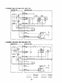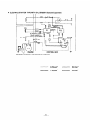
1
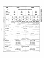
~oIdn
Model
RGD3
G
ator
O/RGDSOOO
I ISSUE EMD-GS0572
]
CONTENTS
Page
Title
Section
1. SPECIFICATIONS
.: .....
........................................
2
2
2. PERFORMANCE ...............................................
2-1
Model RGD3700
Model RGD5000 .........................................
2-2
2-3
DC Output
3. FEATURES
4. GENERAL
4- 1
4-2
4-3
7
. ...........
OF GENERATOR
.......................
External View of Generator .................................
Control Panel ............................................
Location of Serial Number and Specification
Number
5. CONSTRUCTION
5-1
5-2
5-3
5
.....................................
DESCRIPTION
AND FUNCTION
.............
..............................
Construction
............................................
Function
...............................................
Description of Generator Operation ...........................
6. SAFETY PRECAUTIONS
.......................................
7. RANGE OF APPLICATIONS
....................................
PROCEDURES
....................................
Measuring Instruments
.....................................
AC Output Measuring
.....................................
Measuring Insulation Resistance ..............................
8. MEASURING
8-1
8-2
8-3
9. CHECKING
9-1
9-2
9-3
-9-4
9-5
9-6
9-7
FUNCTIONAL
MEMBERS ............................
Pilot Lamp ...............................................
AC Receptacles ..........................................
Curcuit Breaker
..........................................
Stator ..................................................
Rotor ..................................................
Condenser
.......
.._ ....................................
Diode Rectifier
...........................................
10. DISASSEMBLY AND ASSEMBLY
10-1
10-2
10-3
10-4
10-5
1
................................
Preparation and Precautions .................................
Special Tools for Disassembly and Assembly
....................
Disassembly Procedures ....................................
Assembly Procedures ......................................
Checking, Disassembly and Reassembly of the Control Box .........
8
9
9
10
18
19
19
19
23
26
27
30
30
32
32
34
34
34
35
35
36
37
37
38
38
38
39
48
59
Section
Page
Title
11. TROUBLE SHOOTING .........................................
11-1
11-2
11-3
11-4
No AC Output
...........................................
AC voltage is too high or too low ..
...........................
AC voltage is normal at no-load, but the load cannot be applied
No DC Output
...........................................
12. WIRING DIAGRAM
...........................................
60
.....
60
62
63
64
65
Model
__~.
.-.
Type
-._ .-
RGD3700
-
Brushless, Revolving Field, Self-exciting,
_.
6OHZ
_--.
.-
Frequency
-Maximum Output
50Hz
-.-3500w
.
-
3300w
__
.
Rated
Current
Model
.-.
4BOOW
11ov
-.30.OA
-._.. . _
11ov
120v
27.5A
220V
_-.
220v
Voltage
Power Factor
._-- .
DC output
-.
-Voltage Reyulator
.
Voltaye Regulation
.&C
2-pole, Single Phase
- ._ ._50Hz
3700w
3ooow
Rated Output
RGD5000
.- -_-__- I
30.OAf15.OA
27.5AlI
._
3.8A
. ..___
_.
__---
Air-Cooled
39.lAll9.5A
__---..--._
10%
-----.
_
4-Cycle Diesel Engine
.. -.
-.____
.
I
--
17.9A
_-_
Within
- --
19.5A
-
(1OOW)
-_.
Condenser Type
-.-.
-
-
12V-8.3A
_.
39.1A
_-_
1.0
-
-__
_-
240V
_ _._.
1 lOVi22OV
15.OA
1 lOVf22OV
.12OVl24OV
-_.._
.-
-
4300w
-
-.-
SOHi
5ooow
4500w
11ov
120\/’
22OV
11 OVl22OV
-12OVf24OV
__
..40.9A -
--37.5A
. .__ _
20.5A
40.9Af 20.5A
37.5All8.8A
__,--
--_.
,,-.-
._ -_
- ___
-
.__._-__
,_.
.-_-
--
.--
Displacement
- _.._
Maximum Output.
-----._
.Fuel
-.._-.
Fuel Tank Capacity
---__
Fuel Consumption
6.0 PSI3000 rpm
-. _...14 liters (3.6 U.S. gal.)
.-..__--.
50Hz: 1.2 liters/hour
6OHz: 1.5 liters/hour
._.. .
1 .O liter (2.1 U.S. pints)
.._. -_-_.
Ratio
.--
Oil Capacity
_.Starting System
Dimensions
.
.-
-..
L x W x H
__
Dry Weight
Automotive
.--
._ .
673 x 500 x 514 mm
(26.5 x 19.7 x 20.2 in.)
. ..__.---..85 kg (186 Ibs.)
._
type, Diesel Fuel
__
-----_.
-.
_-
.-
1
-__
Recoil starter and Electric starter
-.
.-
--I-
--.
.16 liters (4.2 U.S. gal.)
__--.- .__..50Hz: 1.7 liters/hour
60Hz: 2.0 liters/hour
- -1 .l liters (2.3 U.S. pints)
-- . ..__
-. ._673 x 500 x 542 mm
(26.5 x 19.7 x 21.3 in.)
---...., _i9 kg (218 Ibs.)
____-
__-.---
2. PERFORMANCE CURVES
2-l
MODEL RGD3700
RGD3700
N
=
;r
y
Output Max.
52
51
Rated
Y50
t
49
3k
aIL
120
,’
110
2
l-
100
5:
..............
3500W
3000W
Frequency .................
50Hz
Voltage ...................
11ov
I
2
I*
...............
z
kz
lk
2
?
0
5
10
15
20
CURRENT IA)-
25
30
35
RGD3700
63
Output Max.
62
..............
3700W
61
Rated
60
Frequency .................
60Hz
Voltage ...................
120v
CURRENT
3300W
(A) -
L
I 53
2 52
4
Y
...............
RGD3700
Output Max.
...............
3500W
51
Rated
50
Frequency .................
50Hz
49
Voltage.
220v
El
z
I
230
z’
220
210
%
?
0
5
CURRENT
10
(A) -
15
-2-
..............
..................
3000W
RGD3700
63 -
-4k
Output Max.
62
Rated
61
-3k
I
60
59
-2k
230
-1k
z
;
...............
..............
3700W
3300W
Frequency .................
60Hz
Voltage.
220v
..................
c
i$
220
210
0
10
15
5
CURRENT (A) -
20
RGD3700
53
Output Max.
52
...............
..............
3500W
51
Rated
3000W
50
Frequency .................
50Hz
Voltage ...................
240V
250
240
230
10
0
:“RRENT
14
(A) -
RGD3700
53
Output Max.
52
Rated
51
...............
..............
Frequency .................
Voltage ................
I
--3k
230
i
220
z
210
. . 2k 5
a
5
lk0
t
0
5
10
15
CURRENT
20
(Al -
25
30
-3-
3500W
3OOOW
50Hz
1 lOVl22OV
I
RGD3700
62
63
Output Max.
9
6t
z
60
5
59
2
;
230
u
220
I
210
120
2
110
;
100
Rated
...............
..............
-4k
Frequency .................
-3k
Voltage ................
t
3700W
33OOW
6OHz
1 lOVI22OV
3
-2k
';
2
-1k
2
-0
$1111111111111111
>
0
5
10
15
CURRENT
20
(A)-
25
30
35
RGD3700
Output Max.
z
61
$
60
":
cl
59
I
Rated
130
;
120
g
110
..............
Frequency : ................
Voltage.
230
s
‘;;
...............
I
0
I
I
5
I
I
I
I I I I I I I I I
10
15
CURRENT
20
IA) -
25
30
35
-4-
...............
3700W
3300W
6OHz
12OVl24OV
2-2
MODEL RGD5000
53
RGD5000
52
Output Max.
51
Rated
-4k
50
0
10
20
CURRENT (A)-
30
-3k
f
-2k
z
bj
-1k
E
2
...............
..............
4800W
4300W
Frequency .................
50Hz
Voltage ...................
11ov
40
RGD5000
;
63
E
62
z”
Lu
2
UJ
a
II.
61
Output Max.
-5k
Rated
-4k
60
-3k
I
e
-2k
2
-1k
2
o
59
...............
..............
5000W
4500W
Frequency .................
60Hz
Voltage ...................
120v
-0
0
t
10
20
CURRENT
30
40
50
(AJ-
52
53
RGD5000
- 5k
Output Max.
I
Rated
-- 4k
51
I
Ill
.*3k
49
E
.,2k
2
2
2
+
. . lk
230
5
1.
r
0
5
10
CURRENT
15
(A) -
20
25
-5-
...............
..............
4800W
4300W
Frequency .................
50Hz
Voltage ...................
220v
RGD5000
63
- 5k
Output Max.
62
61
...............
Rated
.4k
60
-3k
I
-2k
3
5
-1k
2
‘0
..............
5000W
4500W
Frequency .................
60Hz
Voltage ...................
220v
-0
0
5
10
CURRENT
15
20
(Al -
53
- 5k
RGD5000
Output
. . 4k
...............
Rated
r
t
3
-
Max.
..............
4800W
4300W
Frequency .................
50Hz
Voltage ...................
240V
250
240
-0
230
z
2
J
F
0
5
lo
CURRENT
15
(A) -
20
25
A 53
RDG5000
52
p
51
;
50
Y
Output Max.
...............
Rated
49
Frequency.
5k
I
4k
j2k
lk
I 0
>
i’
0
5
10
15
20
CURRENT
25
30
35
40
45
(Al -
-6-
..............
................
Voltage ................
t
g
o
4800W
4300W
50Hz
1 lOVf22OV
63
I
--
FREQUENCY
62
2
61
4
60
5
I
I
I
I
RGD5000
I
Output Max. . . . . . . . . . . . . . . . 5000W
(22OVb-,
5k
59
I
3k
s
5
E
s
220
I
210
2k
120
lk
2
w
a
110
$
loo1
. . . . . . . . . . . . . . 4500W
Frequency . . . . . . . . . . . . . . . . .
4k
,o
.Fy
230
Rated
Voltage..
60Hz
. . . . . . . . . . . . . . llOV/12OV
0
>
1
1
5
1
1
1
10
1
1
1
15
1
20
CURRENT
1
25
1
1
30
1
1
35
1
1
40
1
1
]
45
(A) -
RGD5000
Output Max.
Rated
...............
..............
Frequency .................
T5k
I-
5000W
4500W
6OHz
Voltage . . . . . . . . . . . . . . . . 12OVI24OV
4k
t
3k
240
A
z
230
I
0
5
10
15
20
25
CURRENT
30
35
40
0
45
(A) -
2-3 DC OUTPUT (RGD3700, RGD5000)
- I
;
14
2
12
g
10
’
‘-cl=4
2
4
CURRENT
6
(A) -
................
12v
DC Ampere
................
8.3A
DC Output
................
1oow
The voltage curve shown in the left indicates the
characteristic of DC output when charging a battery.
The voltage may be decreased by 20% when the resistance load is applied.
NOTE:
0
DC Voltage
6
10
-7-
It is possible to use both DC and AC outputs simultaneously
up to the rated output
in total.
3. FEATURES
3-1 BRUSHLESS ALTERNATOR
Newly developed brushless alternator eliminates troublesome brush maintenance.
3-2 EASY STARTING
Light pull recoil starter accompanied with automatic decompression system makes the new RGD series
generators even easier in starting than gasoline engine generators.
3-3 QUIET OPERATION
The new RGD series generator provides quiet operation by means of:
0 The superb design of intake-exhaust system.
0 Direct injection combustion system.
l A large super silent muffler.
l An efficient low noise air cleaner.
3-4 ECONOMICAL PERFORMANCE
On top of well known diesel economy, the air-cooled Robin diesel engine features direct fuel injection
and special design refinements for extra fuel efficiency.
3-5 OIL SENSOR
The OIL SENSOR automatically shuts the engine off whenever the oil level falls down below a safe level
preventing engine seizure.
3-6 COMPACT, LIGHT WEIGHT
The combination of newly developed brushless alternator and air-cooled single cylinder Robin diesel
engine enables the new RGD series generators to be very compact in size and light in weight.
3-7 RELIABLE
PERFORMANCE
WITH MINIMAL
MAINTENANCE
0 A brushless alternator eliminates troublesome brush maintenance.
l A drip-proof alternator design.
l A trouble free condenser voltage regulator.
l
l
l
A fuseless circuit breaker.
A dust-proof oil-bath air cleaner.
The OIL SENSOR automatically shuts the engine off whenever the oil level falls down below a safe
level preventing engine seizure.
3-8 LONG-LIFE
DURABILITY
0 Compact and smooth running air-cooled Robin diesel engine lasts much longer than the gasoline
engine of the same size.
l Trouble-free brushless alternator with condenser type voltage regulator works all the year round
without any maintenace work.
-8-
4. GENERAL DESCRIPTION OF THE GENERATOR
4- ‘1 EXTERNAL VIEW of GENERATOR
ROCKER
COVER
AC RECEPTACLE
\
SPEED
FULL POWER SWITCH
(DUAL VOLTAGE
TYPE
ONLY)
*TANER
CONTROL
\
/
\
PILOT
LAMP
NO-FUSE
BREAKER
m,y
OIL GALJGF
-
,
DC FUSE
1 1
\
KEY SWITCH
FUEL
INJECTION
PUMP
,
DC TERMINAL
O,L F,LTED
II
FUEL
FUEL
RECOIL
TANK
& TANK
I
Pl-nn-#..^
O~~\~SIIIYC,
EARTH
-----~
MUlOR
(OPTIONI
CAP
\
FUEL
GAUGE
STAR
BATTERY
-9-
(Option)
FILTER
IGROUND)
TERMINAL
4-2 CONTROL PANEL
l
RGD3700:
50Hz-1 lOV, 60Hz-1 lOV, 120V TYPE
VOLTMETER
NO-FUSE
DC FUSE
0
BREAKER
/C
NO-FUSE
I
BREAKE9
ON
i
I
1
i
I
I
I1
3FF
0
J
1
11OV
. RGD3700:
RECEPTACLE
EARTH
(GROUND)
TERMINAL
DC OUTPUT
START
SWITCH
TERMINAL
50Hz-220V, 24OV, 60Hz-220V TYPE
VOLTMETER
DC F USE
NO-FUSE
BREAKER
\STAR
AC RECEPTACLE
EARTH
(GROUND)
TERtilNAL
-
10-
DC OUTPUT
TERMINAL
T SWITCH
. RGD3700:
50Hz-1 lOV/22OV, 60Hz-1 lOV/22OV TYPE
VOLTMETER
FULL
POWER
SWITCH
DC FUSE
NO-FUSE
BREAKER
/
220V
RECEPTACLE
&
0
START
11OV
. RGD3700:
1lOV
RECEPTACLE
EARTH
(GROUND)
TERMINAL
DC OUTPUT
SWITCH
TERMINAL
U.K., 50Hz-1 lOV/22OV [BS RECEPTACLE]
RECEPTACLE
VOLTMETER
VOLTAGE
CHANGEOVER
SWITCH
NO-FUSE
BREAKER
DC FUSE
0
X0-iCSE
220V
RECEPTACLE
WARNING
LAMP
IOIL SENSOR)
SSEAKER
START
- 11-
/
:
SWITCH
EARTH (GROUND)
TERMINAL
DC OUTPUT
TERMINAL
RGD3700: GERMANY, 50Hz-220V
l
DC FUSE
VOLTMETER
NO-F
:u SE
BREAUER
\
i
WARNING
LAMP
(01 L SENSOR)
/
y
/
START
SWITCH
/
220V
l
RECEPTACLE
EARTH
(GROUND)
TERMINAL
DC OUTPUT
TERMINAL
RGD3700: 50Hz-220V [WITH SPECIAL RECEPTACLE]
VOLTMETER
DC FUSE
NO-FUSE
BREAKER
\START
220V
RECEPTACLE
EARTH
(GROUND)
TERMINAL
DC ~UTPUT
TERMINAL
SWITCH
a RGD3700: OCEANIA, 50Hz-240V
VOLTMETER
DC FUSE
NO-FUSE
BREAKER
-.-----START
240V
RECEPTACLE
EARTH
(GROUND)
TEkMlNAL
- 13-
DC OUTPUT
TERMINAL
SWITCH
RGD5000: 50Hz-1 lOV, 60Hz-1 lOV, 120V TYPE
l
NO-FUSE
DC FUSE
VOLTMETER
BREAKER
’
r’
1
J
0
- - -J
L
I,
AC
1lOV
O
OEi
0
START
11OV
l
RECEPTACLE
EARTH
(GROUND)
DC OUTPUT
TERMINAL
SWITCH
TERMINAL
RGO5000: 50Hz-220V, 24OV, 60Hz-220V TYPE
DC F
VOLTMETER
usE
I
NO-FUSE
[
NO-FL.%
BREAKER
BREXIJ/
-START
220V
RECEPTACLE
EARTH
(GROUND)
- 14-
TERMINAL
DC OUTPUT
TERMINAL
SWITCH
. RGD5000:
50Ht-1 lOV/22OV, 60Hz-llOV/220V
VOLTMETER
FULL
TYPE
POWER
SWITCH
DC FUSE
NO-FUSE
BREAKER
-START
11OV
. RGD5000:
11OV
RECEPTACLE
RECEPTACLE
EARTH
(GROUND)
TkRMINAL
DC ~JTPUT
SWITCH
TERMINAL
U. K., 50Hz-1 lOV/22OV [BS RECEPTACLE]
VOLTMETER
VOLTAGE
CHANGEOVER
SWITCH
NO-FUSE
BREAKER
DC FUSE
/
220V
RECEPTACLE
START
WARNING
LAMP
(01 L SENSOR)
-
15-
SWITCH
EARTH (GROUND)
TERMINAL
DC OUTPUT
TERMINAL
a RG05000:
U.S.A., 60Hz-120V/240V
PILOT
240V
[NEMA RECEPTACLE]
LAMP
FULL
POWER
SWITCH
NO-FUSE
BREAKER
RECEPTACLE
\
WARNING
LAMP
(OIL SENSOR)
1
12OV
l
RECEPTACLE
EARTH
(GROUND)
START
SWITCH
TERMINAL
RGD5000: GERMANY, 50Hz-220V
VOLTMETER
DC FC
NO-FUSE
BREAKER
\
i
J
(
AC
22CV
I
\
0
OFi
’
J
/
1
220V
RECEPTACLE
EARTH
(GROUND)
TERMINAL
- 16-
DC OUTPUT
TERMINAL
WARNING
LAMP
(01 L SENSOR)
.
START
SWITCH
. RGD5000: 50Hz-220V [WITH SPECIAL RECEPTACLE]
DC FUSE
VOLTMETER
NO-FUSE
BREAKER
-
220V
l
EARTH
RECEPTACLE
(GROUND)
TERMINAL
DC OUTPUT
START
SWITCH
START
SWITCH
TERMINAL
RGD5000: OCEANIA, 50Hz-240V
DC FUSE
I
VOLTMETER
\
NO-FUSE
I
BREAKER
”
J
1
240V
RECEPTACLE
EARTH
(GROUND)
TERMINAL
-17-
DC OUTPUT
TERMINAL
4.3
LOCATION of SERIAL NUMBER and SPECIFICATION
NUMBER
Serial number is stamped on the LABEL (MODEL NAME) stuck on the rear cover.
Specification number is stamped on the stator cover.
NOTE:
SERIAL
Always specify these numbers when inquiring
to get correct parts and accurate service.
NUMB
- 18-
about
the generator
or ordering
spare parts in order
5. CONSTRUCTION
5-l
AND FUNCTION
CONSTRUCTION
RECOIL
STARTER
STATOR
ROTOR
\
COMP
COMPLETE
ROUGH
MOUNT
STARTER
RUBBER
/
GENERATOR
BASE
STATOR
COMPLETE
SUPPORT
UPPORT
\
DRIVING
DRI-VING
BALL
BEARING
I
SHAFT
ADAPTER
Fig. 5-l
5-2 FUNCTION
5-2- 1 STATOR
The stator consists of a laminated silicon steel sheet
core: a main coil and a condenser coil which are
wound in the core slots.
The condenser coil excites the rotor field coil which
generates AC voltage in the main coil.
Fig. 5-2
- 19-
RING
BOLT
PULLEY
\
BOLT
FLYWHEEL
5-2-2
CONDENSER
Two condensers are installed in the control box and
are connected to the condenser coil of the stator.
These condensers and condenser coil regulate the
output voltage.
I
I
Fig. 5-3
5-2-3
ROTOR
The rotor consists of a laminated silicon steel sheet
core and a field coil which is wound over the core.
DC current in the field coil magnetizes the steel
sheet core. Two permanent magnets are provided for
the primary exciting action.
Fig. 5-4
A diode rectifier
and surge absorber is mounted inside of the insulator.
GE ABSORBER
Fig. 5-5B
Fig. 5-5A
-20-
5-2-4
(1)
FUSE
The 10 ampere DC fuse mounted on the control panel protects whole DC circuit from getting damage by overload or short circuit.
(2)
The 15 ampere DC fuse in the control box protects the diode rectifier from getting damage
by reverse connection to the battery.
Fig. 5-6
5-2-5
NO-FUSE BREAKER
The no-fuse breaker protects the generator from getting damage by overloading or short circuit in the appliance. Table 5-l shows the capacity of no-fuse breaker by each spec. and their object of protection.
MODEL
1
I
RGD3700
SPECIFICATION
11ov. 120v
1
!
NO-FUSE
BREAKER
1 OBJECT of PROTECTION
27A
Total output amperage
,
I
! 110/22OV,
120/24OV
) “OV j
12OV
iiA
!o”~~~~ff~~~cle
1
Output from 30A receptacle
30A
RGD5000
I
220v
240V
t
I
20A
I
I
Total output amperage
18A
!
Total output amperage
20Ax2
110’22OV.
Total output amperage
120/24OV ’
30A
Output from 30A receptacle
Table 5- 7
I
Fig. 5-7
-21-
5-2-6
RECEPTACLE and AC PLUG (STD. SPEC.)
These are used for taking AC output power from the generator. A total of five kinds of receptacles, each
varying in rated voltage and current from another, are used. Each model has at least one receptacle to deliver
the rated generator output. As many AC plugs as the receptacles, each matching the corresponding receptacle,
are provided. Table 5-2 shows the rated current for each receptacle. Be careful not to use the receptacles and
AC plugs beyond the specified limits to prevent burning.
up to total 15 amperes
.gp@, ( from
two receptacles
I
l&i&
L&
Ym
‘i-&
!
up to 15 amperes
up to 20 amperes
Caution:
Table 5- 2
To connect the appliance to locking receptacle, insert
the plug into the receptacle and turn it clockwise to
lock.
Fig. 5-8
NOTE:
If your generator
NOTE:
The generator for U.S. A. market is equipped with NEMA standard receptacles shown in table 5-3.
Use the proper plug for connecting appliance to the generator.
Style
has receptacles peculiar
I
Ampere
to your country,
I
i Receptacle
1
AC plug
I
Table 5- 2 does not apply.
,
I
Description
GFCI
(Ground Fault Circuit
Interrupter 1
Receptacle, duplex
125Vz25OV
20A
!
NEMA
Ll4-20R
I
NEMA
L14-20P
Locking Receptacle
I
125V
30A
,
NEMA
L5-30
1
I
I
Table 5- 3
- 22 -
NEMA
L5-3OP
;
Locking Receptacle
5-3 DESCRIPTION of GENERATOR
PERMANENT
FOR INITIAL
MAGNET
EXCITATION
OPERATION
STATOR
MAIN
COIL
RECEPTACLE
SURGE
ABSORBER
CONDENSER
COIL
CONDENSER
Fig. 5-9
5-3-l
GENERATION
of NO-LOAD VOLTAGE
(1)
When the generator starts running, the permanent magnet built-in to the rotor generates 3 to 6V of AC
voltage in the main coil and condenser coil wound on the stator.
(2)
As two condensers are connected to the condenser coil, the small voltage at the condenser coil generates
a minute current @ which flows through the condenser coil. At this time, a small flux is produced
with which the magnetic force at the rotor’s magnetic pole is intensified. When this magnetic force is
intensified, the respective voltages in the main coil and condenser coil rise up. As the current @ increases, the magnetic flux at the rotor’s magnetic pole increases further. Thus the voltages at the main
coil and condenser coil keep rising by repeating this process.
(3)
As AC current flows through the condenser coil. the density of magnetic flux in the rotor changes. This
change of magnetic flux induces AC voltage in the field coil, and the diode rectifier in the field coil
circuit rectifies this AC voltage into DC. Thus a DC current flows through the field coil and magnetizes
the rotor core to generate an output voltage in the main coil.
(4)
When generator speed reaches 2700 to 2800 rpm (50Hz type) or 3000 to 3300 rpm (60Hz type), the
current in the condenser coil and field coil increases rapidly.
This acts to stabilize the output voltage of each coils. If generator speed further increases to the rated
value, the generator output voltage will reach to the rated value.
5-3-2
VOLTAGE
FLUCTUATIONS
UNDER LOAD
When the output current @ flows through the main coil to the appliance, a magnetic flux is produced and
serves to increase current @ in the condenser coil. When current @ increases, the density of magnetic flux
across the rotor core rises. As a result, the current flowing in the field coil increases and the generator output
voltage is prevented from decreasing.
- 23 -
5-3-3
FULL POWER SWITCH (Dual Voltage Type)
The full power switch is provided for the dual voltage type to take out the full rated power from one receptacle in each voltage.
120124OV
r---1~0r110/220V)
Fig. 5- 10
Fig. 5-11
Switch
Position
11ov
LOWER VOLTAGE
RECEPTACLE
’
Rated output
! HIGHER VOLTAGE
RECEPTACLE
I
No output
can be taken.
I&
Half of rated
output
Table 5-4
Fig. 5-12
-24-
Rated output
1
Inside the generator are two sets of main coils. Each main coil outputs half the rated power at the lower voltage (11OV or 120V). These main coils are wound to be in the same phase. The full power switch reconnects
these main coils in parallel or in series.
Fig. S-10 shows a circuit diagram. When the full power switch is set for single lower voltage indication (11OV
or 12OV), the switch position is as indicated by the lower solid line in the diagram. Fig. 5-l 1 is a simplified
representation of this circuit, showing the two main coils connected in parallel. In this case, the higher voltage (220V or 240V) at Rec. 3 cannot be taken out. Rec. 2 for the lower voltage can output up to the rated
power (up to 30A if the rated current is over 30A), and Rec. 1 can output up to a total of 1SA.
When the full power switch is set for double voltage indication (11OV’XOV or 12OV!24OV), the switch
position is as indicated by the upper dotted line in Fig. 5-10. Fig. 5-l 2 is a simplified representation of this
circuit, showing the two main coils connected in series. In this case: power can be taken simultaneously
from the receptacles for the both voltages. Rec. 3 for the higher voltage can output up to the rated power,
but Rec. 1 and Rec. 3 for the lower voltage can output only up to half the rated power each.
Table 5-4 is a summary of the above explanation. Select the proper output voltage by full power switch in
accordance with the appliance to be used.
5-3-4
VOLTAGE
CHANGEOVER
SWITCH
The generator of 50Hz 1 lOV;‘22OV dual voltage type for U.K. is provided with voltage changeover switch
instead of full power switch.
The output voltage is selected from 11OV and 22OV by turning this switch and both voltages cannot be taken
out simultaneously.
The middle point of the main coil shall be grounded when the changeover switch is turned to 11OV side.
NFB
1lOV
RECEPTACLE
In\
VOLTAGE
CHANGEOVER
SWITCH
I
220v
RECEPTACLE
3
Fig. 5- 13
- 25 -
6. SAFETY PRECAUTIONS
1. Use extreme caution near fuel. A constant danger of explosion or fire exists.
Do not fill the fuel tank while the engine is running. Do not smoke or use open flame near the fuel tank.
Be careful not to spill fuel when refueling. If spilt, wipe it and let dry before starting the engine.
2. Do not place inflammable materials near the generator.
Be careful not to put fuel. matches. gunpowder. oily cloth. straw. and any other inflammables near the
generator.
3. Do not operate the generator in a room, cave or tunnel. Always operate in a well-ventilated area.
Otherwise the engine may overheat and also, the poisonous carbon monoxide contained in the exhaust
gases will endanger human lives. Keep the generator at least 1 m (4 feet) away from structures or facilities during use.
4. Operate the generator on a level surface.
If the generator is tilted or moved during use. there is a danger of fuel spillage and a chance that the generator may tip over.
5. Do not operate with wet hands or in the rain.
Severe electric shock may occur. If the generator is wet by rain or snow: wipe it and thoroughly dry it
before starting.
Don’t pour water over the generator directly nor wash it with water.
If the generator is wet with water. the insulations will be adversely affected and may cause current leakage and electric shock.
6. Do not connect the generator to the commercial power lines.
This may cause a short-circuit or damage to the generator. Use a transfer switch for connecting with indoor wiring.
NOTE:
The parts numbers
Table 6- 1.
of the transfer
,
Allowable
Part No.
Part Name
Q’ty
Phase
365-45604-08
Transfer Switch
1
1
367-45605-08
Transfer Switch
i
1
1
:
30A
340-45606-08
Transfer Switch
!
1
1
;
60A
Plastic 80x
1
1
Plastic Box
1
1
367-43008-08
L
switches and of the plastic box to store them are as shown in
348-43009-08
I
:
Current
15A
30A
I
60A
Table 6- 7
7. Use a fuse of the correct capacity. (.DC output!
If the generator rpm is increased excessively- in the overload condition by using an over rated fuse. the
generator may be burnt.
CAUTION: If the fuse is burnt out or the circuit breaker tripped off as a result of using an electrical
appliance, the cause can be an overload or a short-circuit. In such a case, stop operation immediately and
carefully check the electrical appliance and AC plugs for faulty wiring.
- 26 -
7. RANGE OF APPLICATIONS
Generally. the power rating of an electrical appliance indicates the amount of work that can be done by it.
The electric power required for operating an electrical appliance is not always equal to the output wattage of
the appliance. The electrical appliances generally have a label showing their rated voltage, frequency, and
power consumption (input wattage). The power consumption of an electrical appliance is the power necessary for using it. LVhen using a generator for operating an electrical appliance, the power factor and starting
wattage must be taken into consideration.
In order to determine the right size generator, it is necessary to add the total wattage of all appliances to be
connected to the unit.
Refer to the followings to calcurate the power consumption of each appliance or equipment by its type.
(1)
Incandescent lamp, heater, etc. with a power factor of 1.0
Total power consumption must be equal to or less than the rated output of the generator.
Example: A rated 3OOOWgenerator can turn thirty 1OOWincandescent lamps on.
(2)
Fluorescent lamps, mercury lamps, etc. with a smaller power factor
Select a generator with a rated output equivalent to 1.2 to 2 times of the power consumption of the
load.
Example: A 400W mercury lamp requires 600W to 700W power source to be turned on.
A rated 3OOOWgenerator can power four or five 4OOWmercury lamps.
NOTE
1: if a power factor correction capacitor is not applied to the mercury lamp or fluorescent lamp,
the more power shall be required to drive those lamps.
A rated 3000W generator can drive one or two 4OOW mercury lamps without power factor
correction capacitors.
NOTE 2: Nominal wattage of the fluorescent lamp generally indicates the output wattage of the lamp.
Therefore, if the fluorescent lamp has no special indication as to the power consumption,
efficiency should be taken into account as explained in Item (5) on the following page.
(3)
Motor driven tools and light electrical appliances
Generally the starting wattage of motor driven tools and light electrical appliances are 1.2 to 3 times
larger than their running wattage.
Example: A rated 25OW electric drill requires a 400W generator to start it.
(4)
Initially loaded motor driven appliances such as water pumps, compressors, etc.
These appliances require the large starting wattage which is 3 to 5 times of running wattage.
Example: A rated 900W compressor requires a 45OOWgenerator to drive it.
NOTE
1: Motor-driven
appliances require the aforementioned
generator output only at the starting.
Once their motors are started, the appliances consume about 1.2 to 2 times their rated power
consumption
so that the excess power generated by the generator can be used for other electrical appliances.
NOTE 2: Motor-driven
appliances mentioned in Items (3) and (4) vary in their required motor starting
power depending on the kind of motor and start-up load. If it is difficult
to determine the
optimum generator capacity, select a generator with a larger capacity.
- 27 -
(5)
Appliances without any indication as to power consumption
Some appliances have no indication as to power consumption; but instead the work load (output) is
indicated. In such a case, power consumption is to be worked out according to the numerical formula
mentioned below.
(Output of electrical appliance)
= (Power consumption)
(Efficiency)
Efficiencies of some electrical appliances are as follows:
Single-phase motor . . . . . . . . . . . . . . . . 0.6 - 0.75
The smaller the motor, the lower
ItThree-phase motor . . . . . . . . . . . . . . . . 0.65 - 0.9
the efficiency.
Fluorescent lamp . . . . . . . . . . . . . . . . . . 0.7 - 0.8
Example 1: A 40W fluorescent lamp means that its luminous output is 40W. Its efficiency is 0.7 and
accordingly, power consumption will be 40 + 0.7 = 57W. As explained in Item (2): multiply this power consumption value of 57W by 1.2 - 2 and you will get the figure of the
necessary capacity of a generator. In other words, a generator with a rated output of 1OOOW
capacity can light nine to fourteen 40W fluorescent lamps.
Example 2: Generally speaking, a 400W motor means that its work load is 400W. Efficiency of this
motor is 0.7 and power consumption will be 400 + 0.7 = 570W. When this motor is used
for a motor-driven tool, the capacity of the generator should be multipled by 1.2 to 3 and
570W as explained in the Item (3).
MODEL
I
RGD5000
RGD3700
Frequency
50 Hz
60Hz
lncandesent
lamp, heater, etc.
3,000w
Fluorescent
lamp, mercury lamp, etc.
Motor-driven
tool, general-purpose
Water pump, compressor, etc.
motor, etc. i
50 Hz
60 Hz
3,300w
4,300w
4,500w
approx.
2,000w
approx.
2,200w
approx.
2,aoow
approx.
3,000w
approx.
1,800W
approx.
1,900w
approx.
2,600W
approx.
2,700W
approx.
950w
approx.
1,250W
approx.
1,300w
approx.
9OOW
Table 7- 7
- 28 -
:
i
!
1
NOTES:
Wiring between generator
and electrical
appliances
1. Allowable current of cable
Use a cable with an allowable current that is larger than the rated input current of the load (electrical
appliance). If the input current is larger than the allowable current of the cable used, the cable will become excessively heated and deteriorate the insulation, possibly burning it out.
Table 7-2 shows cables and their allowable currents for your reference.
2.
Voltage drop in long electric extension cords
When a long wire is used to connect an appliance with the generator, a certain amount of voltage drop
occurs in the wire which lessens effective voltage available to the appliance.
The table below has been prepared to illustrate the approximate
voltage loss when an extension cord
of 300 feet (approx. 100 meters) is used to connect an appliance or tool to the generator.
I
Nominal cross
section
1
A.W.G.
GaugeNo.
1 Allowable
!
current
1
Resistance
I
Current
8V
12.5V!-
30 0.18
1
2.477
2.5
16
12
50 0.18
’
1.486
! 1.5v
5v
’
7.5v
14
17
37 0 26
0952
’
1V
3V
,
I
5V
5.5
12-10,
1
10-8
23
1
35
!Z 100m
5A
7
3.5
mm
3A
18
2.0
No
1A
0.75
i
A
’
No.
1.27
Amp.
dia.
mm2
I
I
1 ~~$s,strand
45.0.32
I
70 0.32
0 517
/
0.332
;
1
8A
10A
12A
15A
-
-
-
1 12v
15v
18V
-
8V
1ov
12v
15v
-
1.5v
2.5V
4V
-
1v
2v
2.5V
:
5V
1 3.5V
I
6.5V
7.5v
4V
5V
8
*
1
’
s
Table 7- 2
1
xRxlxE
100
R means resistance (!A 100 m ) on the above table.
I means electric current through the M-ire (XI.
6 means the length of the Loire im).
The length of the kvire indicates round length. it means twice the length from generator to electrical
tools.
Voltage drop indicates as 1. = -
- 29 -
8. MEASURING PROCEDURES
8-1 MEASURING
8-l-l
INSTRUMENTS
VOLTMETER
-
AC voltmeter is necessary’.The approximate AC voltage ranges of the voltmeters to be used for various
types of generators are as follows:
0 to 1SOV: Type with an output voltage of 110 or
1ZOV
0 to 300V: Type with an output voltage of 220.
230, or 240V
0 to 15OV, 0 to 3OOV: Dual voltage type
FOR
AC
I
I
Fig. 8- 1
8-l -2 AMMETER
AC ammeter is necessary. An AC ammeter with a
range that can be changed according to the current
rating of a given generator is most desirable. (About
1OA, 20A, 1OOA)
FOR
AC
Fig. 8-2
8-l-3
FREQUENCY METER
Frequency range: .4bout 45 to 65Hz
NOTE:
Be careful
voltage
of the
frequency
meter’s
input
range.
Fig. 8-3
-30-
8-l-4
TESTER
Used for measuring resistance. etc.
Fig. 8-4
8-l-5
MEGGER TESTER
Used for measuring generator insulation resistance.
Select one with testing voltage range of 5001-.
Fig. 8-5
8-l-6
TACHOMETER
There are various types of tachometers. such as contactless type. contact type. and strobe type. The
contact type can be used only a-hen the generator
and engine have been disassembled. The contactless
type is recommended.
CONTACTLESS
TYPE
I
STROB’E
Fig. 8-6
-31-
TYPE
I
8-2
AC OUTPUT MEASURING
SWITCH
LOAD
Fig. 8-7
-
Use a circuit like the one shown in Fig. 8 -7 for measuring XC output. X hot plate or lamp with a power factor of 1.O may be used as a load. Adjust the load and rpm. and check that the voltage range is as specified in
Table 8- 1 at the rated amperage and rated rpm.
Rated voltage
Voltage
range
1lOV
12ov
107-119v
117-
22ov
130v
215-238
1
240V
235-
Table 8- 1
8-3
MEASURING
INSULATION
RESISTANCE
Connect a megger tester to one of receptacle output
terminals and the ground terminal, then measure the
insulation resistance. An insulation resistance of 1
megohm or more is normal. (The original insulation
resistance at the time of shipment from the factory
is 10 megohms or more.)
If it is less than 1 mepohm. disassemble the generator and measure the insulation resistance of the
stator, rotor and control panel individually.
MEGGER
TESTER
Fig. 8-8
. STATOR
(1) Measure the insulation resistance
BLUE lead and the core.
(2) Measure the insulation resistance
WHITE lead and the core.
(3) Measure the insulation resistance
YELLOW lead and the core.
(4) Measure the insulation resistance
BROWN lead and the core.
between
between
between
between
Fig. 8-9
- 32 -
260
ROTOR
Measure the insulation across one of the soldered
terminals of the rotor and the core.
l
Fig. 8- 10
. CONTROL PANEL
Measure the insulation resistances between the live
parts and the grounded parts.
Fig. 8- 11
Any part where the insulation resistance is less than 1MS1 has faulty insulation: and may cause electric leakage and electric shock.
Replace the faulty part.
- 33 -
9. CHECKING FUNCTIONAL
MEMBERS
9-1 PILOT LAMP
Check the pilot lamp if it is turned on by applying
specified \-oltage.
Pilot lamp cannot be checked with circuit tester because its resistance is too large. (See Fig. 9- 1.i
Fig. 9- 7
a RGD3700, RGD5000. . . . . . . . . . . . . Pilot lamp should be turned on at 70 to 12OV.
9-2 AC RECEPTACLES
Using a circuit tester. check continuity between the two terminals at the rear of the AC receptacles while the
receptacle is mounted on the control panel. iThen continuity is found between the output terminals of the
receptacle with a wire connected across these terminals, the AC receptacle is normal. When the wire is removed and no continuity is found between these terminals. the receptacles are also normal.
AC RECEPTACLE
Fig. 9-28 (Rear]
Fig. 9-2A (Front)
- 34 -
9-3 CIRCUIT BREAKER
Check continuity between each of two terminals at
the rear of the circuit breaker while it is mounted on
the control panel. Normally, there is continuity between each of the two when the circuit breaker is on
while there is no continuity when the circuit breaker
is off.
IT BREAKER
Fig. 9-3
9-4 STATOR
Disengage connectors on the wires from stator and
check the resistance between wires with a circuit
tester referring to the following table.
d-h.
STATOR
I
I
Fig. 9-4
(R x 1R 210%)
MODEL
Hz 1
I
220v
110v/220v
, 50
RGD3700
!
1
i -
jw;
RGD5000
r 5oi
60
L
1
240V
220v
1 lOVi22OV
120v
12OV/24OV
11ov
I
I
I
;g;;
:
I
I
AC Winding
White-Red
!
Black-Blue
I
SPECIFICATION
Voltage
1 IOV
240V
12OV:24OV
’
/
0.68
0.68
0.84
0.84
0.56
0.56
0.56
II
1
’
0.34
aI;
0.26
i
0.56
Condenser Winding
Yellow-Yellow
1.35
j
1.35
0.98
I
0.98
0.34
0.80
cl:rl;
0.;;
0.26
0.57
Table 9- 1
NOTE:
If the circuit tester is not sufficientlly
accurate, it may not show the values given and may give erroneous readings.
Erroneous readings will also occur when there is a wide variation of resistance among coil windings
.
or when measurement is performed at ambient temperatures different from 20°C /68”F).
- 35 -
9-5 ROTOR ASSEMBLY
(R x 1n &IO%)
1) Using the circuit tester, measure the resistance
of the field coil.
I
MODEL
Resistance
; RGD3700
2.1s2
Table 9-2
NOTE
1: Measure the resistance of each coil winding while the diode and each resistor are
disconnected with their solder removed.
NOTE 2: If the circuit tester is not sufficiently
accurate, it may not show the values given
and may give erroneous readings.
Erroneous reading will also occur when
there is a wide variation
of resistance
among coil windings or when measurement is performed
at ambient temperatures different from 20°C (68°F).
Fig. 9-5
2) Check if the surge absorber is burnt.
Check the resistance of surge absorber.
ILormal resistance is ~!2.
Fig. 9-6
3) Measure the resistance of the diode.
[Continuity
POLARITY
CIRCUIT
OF
TESTER
exists.]
Fig. 9- 7
- 36 -
/ RGD5000
1.6R
1
9-6 CONDENSER
w If an instrument (QC-meter or C-meter) for measuring capacity of condender is available, check
the capacity of condenser. (See Fig.9-8.)
Fig. 9-8
n
NORMAL CAPACITY OF CONDENSER
I
RGD3700
;
RGD5000
MODEL
0,
CAPACITY
@
1
50 Hz
60Hz
5OHz
1 6OHz
2OpF
2OpF
30~ F
’
~QJF
i
2OpF
-
3OpF
3OpF
3OpF
Table 9-3
n
If such an instrument is unavailable. the condenser can be checked by replacing with a new one. If the generator performs.good with new condenser, the cause of trouble is defect in original condenser.
9-7 DIODE RECTIFIER
DIODE
RECTIFIER
Brown
Brown/
White
Orange
Orange
Brown
Brown
0
q
-
0
Brown
II
Brown/White
CIRCUIT
Fig. 9-9
TESTER
Fig. 9- 10
Circuit inside of the diode rectifiers is as shown in Fig. 9-9. Check continuity between each terminal by using
a circuit tester as shown in Fig. 9- 10. The rectifier is normal when continuity is as follows:
Apply black @
needle of the circuit tester
I
Brown
i
Brown
Apply red @ needle
of the circuit tester
i
\
No continuity
Brown
,
No continuity
! Orange
:
Continuity
’ Brown/
White
Brown
I
!
I
; Brown/White
Orange
1 No continuity
Continuity
1
No continuity
Table 9-4
NOTE
7: In checking the diode, direction
teristics of the diode and battery
of connection is contrary to the ordinary
incorporated
in the tester.
case because of charac-
NOTE 2: “Continuity”
means forward direction characteristics of the diode, and different from short circuit
condition
(in which a pointer of the tester goes out of its normal scale), shows resistance to some
extent. When results of the checking indicates failure even in one section, replace with a new one.
10. DISASSEMBLY AND ASSEMBLY
10-l
PREPARATION
and PRECAUTIONS
1) Be sure to memorize the location of individual parts when disassembling the generator so that the generator can be reassembed correctly. Tie tags noted with the necessary information to facilitate easier and
smoother reassembly.
2) For more convenience, divide the parts into several groups and store them in boxes.
3) To prevent bolts and nuts from being misplaced or installed incorrectly-, place them temporarily back at
their original position.
4) Handle disassembled parts with care; clean them before reassembly using a neutral cleaning fluid.
5) Use all disassembly;assembly tools properly. and use the proper tool for each specific job.
10-2 SPECIAL TOOLS for DISASSEMBLY and ASSEMBLY
ROTOR
PULLER
REAR
COVER
PULLER
- 38 -
JIG
10-3 DISASSEMBLY
‘tep
1
PROCEDURES
Part to remove
Fuel Tank
Description
Remarks
(1) Discharge fuel from the tank.
1. Turn the fuel cock to close (S).
2. Disconnect the rubber pipe from the
injection pump. (See Fig. 10-l.)
3. Turn the fuel cock to OPEN (0) to
discharge the fuel.
I (2) Disconnect the fuel pipe and return pipe
from the tank bottom. (See Fig. 10-2.)
1. Remove the hose clamp and pull the
fuel pipe off from the tank.
2. Removrethe banjo bolt that fastens
the return pipe.
I
I
I (3) Remove the fuel tank.
After removing the nut and washer, remove the fuel tank. (See Fig. 10-3.)
Do not lose the gasket.
Necessary tool
17 mm spanner
Wipe off spilt fuel.
Pliers
Do not lose the gasket
12 mm spanner
12 mm spanner or
box spanner
Pliers
1. Remove the hose clamp. and pull out
12 mm spanner or
box spanner
2. Remove the fuel filter bolt:‘and the
fuel filter.
3
FUEL
INJECTION
PUMP
Fig. 70-2
Fig. 10-l
FUEL
TANK
A
Fig. 70-3
Fig. 10-4
Description
‘art to remove
3attery
:Only electric
starter type)
I
Remarks
! Be careful not to short.
(1) Remove battery cable from battery.
Remove the negative side cable first, and I
then the positive side.
I
10 mm spanner or
box spanner
(3) Remove battery base from the pipe
frame.
60 bolt . . . . . . . . . . . 2 PCS.
BATTERY
Necessary tool
I 10 mm spanner or
box spanner
(2) Remove battery from battery base.
Remove the two nuts that fasten the
battery, and take off the battery holder,
battery bolts, and battery-.
6onut . . . . . . . . . . . Zpcs.
6oNUT
.
60 SPRING
I
_. _.
Zpcs.
WASHER
SPACER
. . . . . . . .
BATTERY
60 BOLT
BATTERY
ANGLE
2 PCS.
BATTERY
BASE
BATTERY
BOLT‘I.
9
Fig. 10-5
-40-
CABLE
Control Box
Remarks
Description
Part to remove
(1) Take off the bushingfrom the bottom
of the control box.
OUT
Fig. IO-6
(2) Take out the grommetfrom the bottom
faceof the control box.
Fig. 10-7
(3)
Pull out the wires for the oil sensorand
electric starter: and removethem from
the connectors.
Fig. 10-8
-41-
Pressthe upperend
andpull out the
bushing.
;tep
Part to remove
3
Control Box
Remarks
Description
Necessary tool
10 mm spanneror
box spanner
(4) Removethe control box from the frame.
6# Washer. . . . . . . . . 3 PCS.
6@bolt . . . . . . . . . . . 3 PCS.
Fig. 70-9
4
RipeFrame
(1) Removesideplate A.
6q3bolt . . . . . . . . . . . 2 PCS.
Removethe mount rubbersfrom side
plate.
(2) Removethe nuts andbolts that fasten
the generatorand frame together.
1. Removethe two bolts which fur the
alternatorto the generatorbase.
2. Removethe four bolts and flange
nuts which fur the engineto the
enginebase.
8@bolt . . . . . . . . . . . 4 PCS.
8# flangenut . . . . . . . 4 PCS.
ENGINE
Nuts areweldedto
the generatorbase.
12 mm spanneror
box spanner
BASE
SIDE PLATE A
-60
&BOLT
Fig. IO- ?O
. . . . . . 4~~s.
-42-
BOLT
. . . . . . 2 PCS.
Step
4
Part to remove
Pipe Frame
Description
Remarks
(3) Lift the generator with a chain block
and dismount from the frame.
(See Fig. 10-l 1.)
I
Necessary tool
Be careful to keep
the belt in place.
Fig. 10-l I
(4) Remove engine base, generator base,
and mount rubbers from frame.
@-~~ONUT
I
. . . . .~PCS.
ENGINE
BASE
RUBBER
RUBBER
Fig. IO- 12
V.I.
. . 1 pee.
w
5
Description
Part to remove
Recoil Starter
Remarks
(1) R.emove recoil
starter from rear cover.
60 bolt . . . . . . . . . . . 4 PCS.
Necessary tool
10 mm spanner or
box spanner
Fig. IO-13
5
Rear Cover
(1) Take off the through bolt and remove
the starting pulley and spacer from rotor
shaft. Apply a box wrench on the head
of through bolt and hit the wrench
handle with a hammer counterclockwise
to loosen.
Be careful not to lose
I the kev at removing
starting pulley.
-
/
I
Fig. lo-14
Fig. 70-15
- 44 -
Box spanner or
I socket wrench
Hammer
Step
6
Part to remove
Rear Cover
Description
Remarks
t (2) Take off the rear cover.
1. Remove the four bolts which fasten
the rear cover to the adapter of the
engine.
64 bolt . . . . . . . . . . , 4 PCS.
2. Use a special tool “REAR COVER
PULLER’ to remove the rear cover.
a) Insert the two bolts of the
special tool into the thread hole
of the rear cover.
b) Apply the center bolt of the
special tool to the center hole
of the rotor shaft.
c) Tighten the center bolt to pull
out the rear cover.
6@ BOLT
. .
REAR
Necessary tool
10 mm spanner or
box spanner
Insert the two bolts
sufficently and evenly
or the thread hole may
be damaged at removing.
Special tool
17 mm spanner
Driver
. . . 4 PCS.
COVER
PULLER
BOLT
OLT
Fig. lo-16
. .
. . 2 PCS.
Fig. lo-17
In case that *REAR COVER PULLER‘ is un; available, remove the rear cover by the followmg instructions.
Do not give a strong
1. Insert the through bolt inro the rotor
hit on the rear cover
shaft and tighten lightly.
boss or legs.
Hit on the boss and legs of rear cover
I
with a plastic hammer.
I
I
Fig. lo-18
Box spanner or
socket wrench
Plastic hammer
Step
Description
Part to remove
Stator
SUPPORT
Remarks
(1) Remove support ring.
1. Remove the four bolts which fasten
the stator to the rear cover.
2. Insert a small hook into the hole
inside of the support ring and pull it
Necessary tool
f
60 BOLT
RING
.
60 SPRING
Fig. lo-19
. .
WASHER
Fig. lo-20
(2j Take apart the stator from the rear cover. 1
NOTE: Use utmost care not to give damage to the stator insulation and stator
leads.
S
I
_
STATOR
SUPPORT
60 WASHER
. 4 PCS.
60 SPRING WASHER
. . . . . . . . . 4 PCS.
&BOLT
Fig. 70-2 1
-46-
.
. .
4pcs.
4 PCS.
ep
Part to remove
$
ROTOR
Description
Remarks
(1) Insert the rotor-puller shaft into the
rotor: and tighten the rotor-puller bolt
until the rotor comes loose.
If the special tool is unavailable, take
the following instructions to remove
the rotor.
Lightly strike the rotor core with plastic
hammer. and pull out the rotor from
the tapered shaft of the engine. If the
rotor cannot be taken off, strike it at
different angles. (See Fig. 10-23.)
17 mm spanner
Sever strike on the coil.
Adaptor and
Driving Shaft
Platic hammer
Fig. lo-23
Fig. lo-22
)
Necessary tool
(1) Remove the four adaptor mounting
bolts, and the adaptor.
8d bolt . . . . . . _ . . 4 PCS.
12 mm spanner
(2) Remove the four driving shaft mounting bolts, and the driving shaft.
100 bolt _ . _ . . . . . . . 4 PCS.
14 mm spanner
89 BOLT
100 BOLT.
100 SPRING
.
I
Fig. lo-24
I
- 47 -
WASHER
. . 4 pcs.
4 PCS.
. .
. 4 PCS.
10-4 ASSEMBLY PROCEDURES
10-4-l
DRIVING
SHAFT and ADAPTOR
(1)
Align the driving shaft with
lO~x30mmbolt
...
104 spring washer . . .
Tightening torque . . . .
the faucet joint
............
............
............
of the flywheel and install it.
. . . . . . . . 4pcs.
. . _ . . _ . . 4 PCS.
. . _ . . . . . 550 m 700 kg-cm
(2)
Install the adaptor in the blower housin g. making sure that its flat side is down and its fuel filter mounting boss on the air cleaner side.
89 x 25 mm bolt
. 4 PCS.
8 Q spring washer . . . . . . . . . . . . . . . . . . . . . . . 4 PCS.
Tightening torque
. 200 - 230 kg-cm
MOUNTING
Fig. 1O-25
10-4-2
ROTOR
(1)
Clean the tapered part of the driving shaft and
the matching tapered part of the rotor shaft of
oil and dirt with a waste cloth.
(2)
Attach the rotor to the engine shaft. Tighten
the through bolt tentatively. (See Fig. 10-26.)
Apply a wrench on the head of through bolt
and hit it clockwise with a hammer to tighten.
Fig. 70-26
- 48 -
BOSS
10-4-3
STATOR
Hookmg
holes for removin
SUppOrt ring
(1 j
Set the stator on the jig so that the grooves on
the stator side match with the grooves of the
jig. At the same time. be sure to set the stator
on the jig so that the lead wires direct to the
window of rear cover.
Attach the support ring around the stator.
Check that the hooking holes are placed at the
flat sides of the stator. (See Fig. 1O-27.)
lllllll
Grooves
DIrectIon
of stator
leads
of stator
STATOR
SUPPORT
Grooves
of jug
JIG
Fig. lo-27
(2)
Insert 4 guide bolts in the rear cover and let
them match with the grooves in the stator and
set the rear cover over the stator.
(3)
Take the stator leads out from the window of
the rear cover.
(4)
Tap lightly and evenly the upper surface of
the rear cover with plastic hammer and press
the rear cover over the stator. (See Fig. lo28.)
BOARD
Fig. 10~28
(5)
Fix the stator to the rear cover with four bolts.
washers and spring washers. (See Fig. 10-29.)
60 bolt . . . . . . . . . .
69 washer . . . . . . . .
60 spring washer . .
Tightening torque . .
.
..
..
..
..
.
..
..
~QBOLT
60
1 PCS.
4 PCS.
4 PCS.
50 - 60 kg-cm
Fig. lo-29
- 49 -
SPRING
. . . . . .4pcs.
WASHER
RING
l
The dimensions of the stator bolts are shown
in Table 10-Z.
Table 10-2
10-4-4
(1)
REAR COVER
Attach the bush over the lead wires draw-n out from the rear cover.
Press the bush end into the window of the rear cover. (See Fig. 10-30.)
Fig. 70-30
(2)
Put the rear cover with stator over the rotor.
Tap on the rear cover evenly with a plastic hammer to press the rotor bearing into the rear
cover. (See Fig. 10-3 1.)
1
1
Fig. IO-31
- 50 -
(3)
Fix the rear cover to the adaptor with four
bolts spring washers. and washers.
(See Fig. 10-32.)
66, x 25 mm bolt . . . . . . 4 pcs.
69 spring washer . . . . . . 4 PCS.
69 washer . . _ . . . . _ . . . 4 PCS.
Tightening torque . . . . . . 50 - 60 kg-cm
Fig. lo-32
10-4-5
RECOIL STARTER
STARTING
(1)
Remove the through bolt which has been tentatively attached to the rotor.
(2)
Insert the key into the keyway of the rotor
shaft. (See Fig. 10-33.)
Then. insert the spacer.
Tapping the starter pulley with a plastic hammer. attach the starter pulley to the rotor shaft.
Fig. 1O-33
(3)
Apply a washer and a spring washer to the through bolt and insert it into the rotor shaft.
1 pee.
Through bolt ...........................
1
pee.
100 spring washer ........................
1 pee.
104 washer .............................
0 T’-L dimension of the through bolt is shown in Table 10-3.
I
c
I
1,,1.,:.,:.I
8.66 inch
/ 1.97 inch
Table 10-3
-51-
1 0.39 inch
PULLEY
(4)
Tighten the through bolt with a box wrench or
a spanner.
If an impact wrench is available, use it.
Tightening torque . . . . . . 240 - 300 kg-cm
Fig. IO-34
(5) Attach the RECOIL
STARTER
to RE;4R
COVER.
69 8 mm flange bolt . . . . 4 PCS.
Tightening torque . . . . . . 40 - 60 kg-cm
RECOIL
STARTER
Fig. lo-35
10-4-6
(1 j
FRAME
Attach two engine mount rubbers and one alternator mount rubber to the frame. (See Fig. 1O-36. j
1Ommnut . . . . . . . . . . . . . . . .._....._.....
?pcs.
Tightening torque . . . . _ . . . . . . . _ . . . . . . . . _ .
n
RUBBER
RUBBER
lOoNUT
V.I.
.
. 2 PCS.
. . . . . . 2 PCS.
\
Fig. lo-36
- 52 -
V.I.
. .
1 pee.
(2)
Attach the engine base to the bottom of the engine. (See Fig. 10-37.)
89xjOmmbolt
. . .._............_......
4pcs.
8@nut . . . . . . . . . .._.................._.
4pcs.
Tightening torque . . . . . . . . _ . . . . . . . . . . . . _ . .I 20 - 140 kg-cm
NOTE:
Insert the bolts from the bottom
-0
*I
0-I
0
ENGINE
MOUNT
side of the engine base.
,
-
RUBBERS-
0
0-I
0
*I
ENGINE
MOUNT
(for RGD3700)
HOLES
-
ENGINE
MOUNT
(for RGD50001
HOLES
Fig. 70-37
(3)
Mount the generator base on the alternator mount rubber and fix with the nut.
8Qnut . . . . . . . . . . _. . . . . . _ . . _ . . . . . . . . . . 1 pee.
Tightening torque . . . . . . . . . . . . . . . . . . . . . . 120 - 140 kg-cm
NOTE:
Set the generator base so that the column
bottom of the generator base.
of the frame is placed in the center of the pipe on the
I
-w.
,=
Make this gap even.
Fig. lo-38
(4)
Install the engine and alternator assembly into
the frame.
a) Lift the engine and alternator assemblp
with a chain block. and down it into the
frame. making sure that the bolts of the
mount rubbers are correctly inserted into
the engine base.
bj Fix the engine and a alternator assembly to
the mount rubbers.
Tighten the t\vo nuts at engine base and
two bolts at generator base.
100 nut . . . . . . . . . . . . . 2 PCS.
Tightening torque . . . . 240 - 300 kg-cm
So x 25 mm bolt
. . . . . 2 PCS.
Tightening torque . . . . . 110 - 140 kg-cm
NOTE:
When tightening the nuts and bolts, slightly
weight is not applied to the mount rubbers.
- 53 -
Fig. 70-39
lift the engine and alternator
assembly SO that the
(5)
Attach the stoppers to the frame.
1: Set the stoppers so that the engine
base is placed in the center of the upper and the lower rubbers. (See Fig.
10-40.)
NOTE 2: If the engine mount rubbers are replaced with new ones, set the stoppers so that the upper rubber touches
the engine base. The new mount rubber shall be distorted b y approx. 3 mm
in one month.
NOTE
Make this gap even.
ENGINE
84x 12mmbolt
. . . . ._ 4pcs.
Tightening torque . . . . . . .120 - 140 kg-cm
(6)
BASE
Fig. lo-40
Attach side plate A to frame.
64x 1Ommbolt
. . . . ._ . . . . . . . . . _. ._. . . . 2pcs.
Attach fuel tank mount rubbers to side plates.
The nuts for mount rubbers are welded to side plates.
Tightening torque . . . . . . . . . . . . . . . . . . . . . . . . 40 - 60 kg-cm
RUBBER
V.I.
SIDE
~BoBOLT
Fig. 70-41
- 54 -
. . . 4 PCS.
PLATE
A
. 2 PCS.
10-4-7
CONTROL BOX
Mount the control box assembly to the frame.
Refer to Section 10-5 for disassembly, checking and
reassembly procedures of the control box.
(1)
Mount the control bos to the frame. (See Fig.
10-42.)
69 x 10mm flange bolt . . . . 3 PCS.
60 Lvasher . . . _ . . . . . . . . . . 3 PCS.
Tightening torque . . . . _ . . . . 40 - 60 kg-cm
(2)
Connect the wires drawn out from the stator to
the wires from the control box. Connect the oil
sensor wires at the same time.
NOTE:
(3)
Connect
Fig. 70-42
the wires of the same color.
Press the upper end of the bushing into the
bottom window of the control box. (See Fig.
10-43.)
Attach the grommet for the oil sensor wires to
the rear panel of the control box.
Fig. lo-43
(4)
Fasten the one earth cable with 84 terminal drawn out from the control box to the rear cover leg.
8@xZ5mmbolt
. . . . . . . . . . . . . . . . . . . . . . . . 1 pee.
Tightening torque . . . . . _ . . . . . . . . . . . . . . . . . 120 - 340 kg-cm
Fasten the other earth cable with 60 terminal to the unpainted bolt hole on the frame. (See Fig. lo-44.j
A
0
60 TERMINAL
0
80 TERMINAL
Fig. lo-44
-
55
10-4-8
BATTERY
(1)
Attach the battery base to the frame.
64x 1Ommbolt . . . . ._ . . . . . . . . . . . . . . . . . . 2pcs.
Tightening torque . . . . . . . . . . . . . . . . . . . . . . . . 40 - 60 kg-cm
(2)
Mount the battery on
10-45.)
6r$nut . . . . . . . .
64 spring washer
Tightening torque
(3)
the battery base. and fix it with two battery bolts and a battery angle. (See Fig.
. . . . . . . . . . . . . . . . . . . . . . . . 2pcs.
. . . . . . . . . . . . . . . . . . . . . . . . 2 PCS.
. . . . . . . . . . . . . . . . . . . . . . . . 40 - 60 kg-cm
Attach battery cords to the battery.
Attach the positive (+) cord first and then the negative (-) cord.
Fasten the other end of the negative (-) cord to the engine base using the engine mount nut.
6oNUT
._...
20~s
60SPRlNG
WASHER
. . . . . . . . .
BATTERY
SPACER
.
. .
BATTERY
6~ BOLT
BATTERY
ANGLE
20~s.
BATTERY
BASE
BATTERY
BOLT-4
R
1
J!J
P
Fig. lo-45
- 56 -
PIPE FRAME
I
CABLE
10-4-g
FUEL TANK
Connect fuel pipe 29 complete and rubber pipe (6 mm inside diameter, 12 mm outside diameter, 170
mm long) to the fuel tank.
a) Connect the rubber pipe and fasten it with the hose clamp (10.5 mm inside diameter).
b) Connect fuel pipe 29 complete to both ends of the banjo and tighten it with banjo bolt using two
pieces of GASKET (ALIJMIXIJM).
Tightening torque . . . . . . . . . . . . . . . . . . . . . . . . 80 - 100 kg-cm
(1)
FUEL
+1
HOSE
CLAMP
INSIDE
DIA.
7.8
*2
HOSE
CLAMP
INSIDE
DIA.
10.5
A
GASKET
BANJO
FUEL
TANK
(ALUMINUM)
BOLT
PIPE 29 COMPLETE
To NOZZLE
CLAMP
r-j+
PURSE
C-J
To CRANKCASE
mm)
CLAMP
BANJO
To INJECTION
w
PUMP
\
RUBBER
LOCK
FUEL
PIPE (60 x 120 x 250 mm)
Fig. 70-46
- 57 -
FILTER
ASSY
(2)
Mount the fuel tank on the
8@nut . . . . . . . . . . . .
84 spring washer . . . .
Tightening torque . . . .
(3)
Connect the fuel pipe.
4 Install the fuel filter assembly on the boss on the side of the adaptor (generator).
8#x65mmbolt
. . . . . . . . . . . . . . . . . . . . . . . . 1 pee.
Connect
the
other
end of the pipe installed in Step (1) to the fuel filter.
b)
Slide the hose clamp over the pipe, connect the pipe to the fuel filter. and clamp the pipe at the correct point.
Then, secure the pipe with the purse lock.
NOTE:
mount rubbers
............
. . . . . . _. . . . .
............
attached to the side plates.
. . . . . . . . 4pcs.
. . . . . . . . 4 PCS.
. . . . . . . . 120 w 140 kg-cm
Connect the shorter pipe of fuel pipe 29 complete to the fuel filter. The hose clamp for the
rubber pipe has an inside diameter of 10.5 mm, and that for fuel pipe 29 complete is 7.8
mm in inside diameter.
cl Connect the longer pipe of fuel pipe 29 complete to the engine nozzle.
The nozzle must be pulled up from the cylinder head before connecting the pipe to it.
After pulling the nozzle up. slide the hose clamp (7.8 mm in inside diameter) over the pipe, connect
the pipe to the nozzle, and fasten the pipe with the hose clamp at the correct point.
Then, install the nozzle on the head.
Mount the bracket on the blower housing, and secure the pipe with the clamp.
d) Connect the fuel filter and injection pump with pipe.
Fit the banjo to the rubber pipe (6 mm in inside diameter, 12 mm in outside diameter, 250 mm
long) and clamp it. Connect the other end of the pipe to the fuel filter and clamp it. Connect the
banjo to the injection pump. A gasket must be placed on each side of the banjo. Use hose clamps
10.5 mm in inside diameter. Finally, clamp the pipe to the crankcase.
- 58 -
10-5 CHECKING, DISASSEMBLY and REASSEMBLY of the CONTROL BOX
10-5-l
CHECKING OF THE CONTROL BOX
Dismount the control box from frame.
Remove the control panel and check each components and wiring.
Refer to Section 9 for the detail of checking the components in the control box.
10-5-2
DISASSEMBLY
REGULATOR
(1)
Remove the control panel from the control
box.
49 screw . . _ . . . . . _ . . . . 8 PCS.
(2)
Disconnect the connectors on the wires to detach the control panel and box.
(3)
Remove the regulator, oil sensor unit, condensers and diode rectifier from the control box.
When removing the regulator. push the hook on
the coupler and pull out to disengage the couplers. (See Fig. 10-47.)
Fig. lo-47
(4)
After disconnecting individual wires, remove the control panel components.
NOTE:
10-5-3
(1)
DC fuse, full power switch, pilot lamp and warning lamp have their wires soldered.
them to remove those parts if necessary,
Unsolder
REASSEMBLY
Install the receptacles, no-fuse breaker, fuse. terminals, switches, etc. on the control panel and wire
them.
NOTE:
Circuit diagrams are shown in Section 12. Colored wires are used for easy identification,
and are
of the correct capacity and size. Use heat-resistant type wires (permissible temperature range
75°C or over) in the specified gauge shown in the circuit diagrams.
(2)
Install regulator, oil sensor unit, condensers, and diode rectifier into the control box.
(3)
Connect the wires of control panel components and control box.
Fasten the earth wires to the rear of the control box using a 69 nut to the bolt which fixes the condenser bracket to the inside of the control box. (See Fig. 10-48.)
(4)
Attach the control panel to the control box.
44 screw . . . . . . _ . . . _ . . . . . _ . . . . . . . . . . . _ 8 PCS.
Tightening torque . . . . . _ . . _ . . _ . . . . . . . . . . . . 12 v 15 kg-cm
To EARTH
TERMINAL
CONDENSER
BRACKET
I
1
Fig. TO-48
-
59 -
11. TROUBLE SHOOTING
11-l
NO AC OUTPUT
11-l-l
n
CHECKING STATOR
Remove control panel and disconnect black, blue.
red, and white wires at the connectors.
w Measure the resistance between terminals on stator leads. (See Fig. 1 l-l .)
Refer to Table 1 l-l for normal resistance. If stator is faulty, replace with a new one.
Fig. 1 I- 1
1-i -1-2
n
CHECKING CONDENSER
If an instrument (QC-meter or C-meter) for measuring capacity of condender is available, check
the capacity of condenser. (See Fig. 1 l-2.)
Fig. 1 1-2
n
NORMAL CAPACITY OF CONDENSER
n
If such an instrument is unavailable. the condenser can be checked by replacing with a new one. If the generator performs good with new condenser. the cause of trouble is defect in original condenser.
-60-
11-1-3
(1)
CHECKING OF ROTOR
CHECKING FIELD COIL
Remove rear cover and stator.
n
8 Unsolder the coil ends from the terminals on the
rotor. (See Fig. 1 l-3.)
Fig. 1 l-3
n
Measure the resistance of field coil with a circuit
tester. (See Fig. 1 l-4.1
n
NORMAL RESISTANCE
I
Table 1 l-2
Fig. 7 l-4
[Remedy]
If the resistance is not normal, replace rotor with a ne\\- one.
(2)
n
CHECKING OF DIODES AND RESISTORS ON THE ROTOR
Unsolder and take out the diodes and a resistor from rotor.
m Measure the resistance of diodes.
POLARITY
CIRCUIT
OF
TESTER
II
q&:
.&l$
:Contlnulty
[=Ol
ex1sts.j
Fig. 1 l-5
Each rotor has three diodes. Check the resistance of each diode.
-61-
Measure the resistance of surge absorber connected to the diode holder.
n
NORMAL
n
RESISTANCE
mR
:
Check the magnetic force of permanent magnets molded in the rotor.
[Remedy]
1. If the magnetic force of rotor magnets is weak. or if the surge absorber is not good. replace the rotor
with a new one.
2. If the diode is not good. replace it with a new one.
CAUTION:
In case the diode troubles are frequent, check the surge absorber because it might be broken even if its resistance is normal ( 00a 1. In such a case, replace the rotor with a new one.
[Reassembling]
\
SURGE
ABSORBER
1. As shown in Fig. 11-6. place the white mark on
the magnet to the left and solder the diodes so
that cathode mark is to be placed at the bottom.
2. Solder the coil ends to the terminal.
DIODE
Fig. 1 l-6
11-2 AC VOLTAGE
11-2-l
IS TOO HIGH OR TOO LOW.
CHECKING STATOR
Check stator referring to Step 11 - 1 - 1.
11-2-2
CHECKING CONDENSER
Check condenser referring to Step 1 1- l-2.
11-2-3
CHECKING ROTOR
Check rotor referring to Step 1 1- l-3.
- 62 -
11-3 AC VOLTAGE
11-3-1
IS NORMAL AT NO-LOAD, BUT THE LOAD CANNOT BE APPLIED.
CHECK THE ENGINE SPEED.
If the engine speed is low, adjust it to the rated r.p.m.
x Refer to Step 11-Z- 1 for engine speed adjustment.
11-3-2
CHECK THE TOTAL WATTAGE OF APPLIANCES CONNECTED TO THE GENERATOR.
Refer to Section 7 “RANGE OF APPLICATIOSS” for the wattage of the appliances.
If the generator is over-loaded. reduce the load to the rated output of the generator.
11-3-3
CHECK THE APPLIANCE
FOR TROUBLE.
If the appliance is faulty, repair it.
11-3-4
CHECK IF THE ENGINE IS OVERHEATED.
If the cooling air inlet andtor cooling air outlet is
clogged with dirt. grass. chaff or other debris, remove it.
Fig. 1 l-7
11-3-5
CHECK THE INSULATION
GENERATOR.
OF THE
Stop the engine. Measure the insulation resistance
between the live terminal of the receptacle and the
ground terminal.
If the insulation resistance is less than 1 M!A2,disassemble the generator and check the insulation
resistance of the stator. rotor and the live parts in
the control box. (Refer to Section 8-3.)
Any part where the insulation resistance is le.ssthan
1 M-2: the insulation is faulty and may cause electric
leakage.
Replace the faulty part.
- 63 -
Fig. 1 l-8
11-4 NO DC OUTPUT
11-4- 1 CHECK THE AC OUTPUT.
Check the generator by following Step 1 1- 1- 1 through Step 1 1- l-3.
11-4-2
CHECK THE DC FUSE.
Check the fuse in the fuse holder.
If the fuse is blown, check for the cause of fuse
blowing, and then replace with a new one.
FUSE : 10A
NOTE:
FUS
If the DC output is used to charge a large
capacity battery or an over-discharged
battery, an excessive current may flow causing
fuse blow.
11-4-3
CHECK THE WIRING.
F&. 11-9
Check all the wires to be connected correctly.
11-4-4
CHECK THE DIODE RECTIFIER.
Remove
fier with
Refer to
checking
the. control panel and check the diode rectia circuit tester.
Section 9-7 “DIODE RECTIFIER” for the
procedure.
Fig. 7 l- 10
11-4-5
CHECK THE DC COIL
Check the resistance between two brown leads from stator with a circuit tester.
‘--I
! 50Hz
RGD5000 1
/ 60Hz
11 OV, 22OV, 240V
11 OV!22OV
’ 120v
) 1 lOV’22OV,
12OV!24OV
I
I
0.16
1
0.13
Table 7 1-3
If the resistance reading is much larger or smaller than the specified value. the DC coil of the stator is faulty.
Replace stator with a new one.
-64-
12. WIRING DIAGRAM
l
RGD3700: 50Hz-1 lOV, 60Hz-1 lOV, 120V TYPE
GENERATOR
CONTROL
--1
/
BOX
I--
--7
L
NFB
-
MC
FC
#
MC
1
r
*
-----------------
l
RGD3700:
50Hz-220V,
GENERATOR
24OV, 60Hz-220V
E”
TYPE
CONTROL
BOX
2.0 mm2
0.75 mm2
-__-___
1.25~~~
-65
-
---
3.5 mm2
l
RGD3700: 50Hz-1 lOV/22OV, 60Hz-1 lOV/22OV TYPE
. RGD3700: U.K., 50Hz-llOV/220V
[BS RECEPTACLE]
GENERATOR
CONTROL BOX
r-1
I
__
NFBl
“C SW-a
m
FC
0.75 mm2
_------
1.25 mm2
- 66 -
2.0 mm2
---
3.5 mm2
l
RGD5000: 50Hz-1 lOV, 60Hz-1 lOV, 120V TYPE
GREEN/YELLOW
E
. RGD5000:
50Hz-220V, 24OV, 60Hz-220V TYPE
GENERATOR
--1
CONTROL BOX
I--
--1
Nz
0
0
7
RECl
0
REC2
,
_----__
- 67 -
mm2
-_-
I
0.75 mm2
2.0 mm2
1.25
3.5 mm2
. RGD5000: 50Hz-1 lOV/22OV, 60Hz-llOV/220V
GENERATOR
TYPE
CONTROL BOX
NFBl
-------
--
. RGD5000: U.K., 50Hz-1 lOV/22OV
GENERATOR
---I
I
__
[BS RECEPTACLE]
CONTROL BOX
-hlCP*
II
111“I
vcswj107
m
R EC3
FC
\NFF
--
--
0.75 mm2
1.25 mm2
--___-- 68 -
2.0 mm2
---
3.5 mm2
. RGD5000: U.S.A., 60Hz-lZOV/240V
iENERATOR--
[NEMA RECEPTACLE]
CONTROL
1
I
BOX
.Icm---
#I
FC
The battery
T
1
!OJ
REC3
Eords have a cross sectional
area of 22 mm*.
2.0 mm2
0.75 mm2
-___--_
1.25 mm2
- 69 -
-_-
3.5 mm2
l
ELECTRIC STARTER TYPE (Optional Equipment)
----I
-
--
j
t
t+
r
3
Irr-C6NTROL
The battery
l
cords have a cross sectional
REG
r
BOX
area of 22 mm*.
TYPE WITH OIL SENSOR (Optional Equipment)
+E,+
---
CONTROL
BOX
-
i -I
0.75 mm2
-------
-70-
1.25mrn2
2.0 mm2
-_-
3.5 mm2
. ELECT ‘RIG STARTER TYPE WITH OIL SENSOR (Optional Equipment)
. a..”
I
I
/
1Y
-
v
The battery
17
r--
-
--A
!
i
PO
ENGINE
cords have a cross sectional
KEY.SW
%---
I
WHITE
-,
L2
Ii
CONTROL
A
-..
-I
:
I
BOX
area of 22 mm’.
2.0 mm2
0.75 mm2
---_--_
-71-
1.25 mm2
-_-
3.5 mm2
Symbols
MC
AC Winding
SC
Auxiliary
DC
DC Winding
FC
Field Winding
I-
I
Parts Name
-r
D
Condenser
1 Diode Stack Assy
Ll
Pilot Lamp
L2
Warning
T
DC Output
I
FI
1 Fuse I
I
F2
I
I
Winding
Lamp (Oil Sensor)
Terminal
Fuse 2
NFBl
No-Fuse
Breaker
NFB2
No-Fuse
Breaker
F PSw
Full Power Switch
REG
Regulator
OS I
Oil Sensor
I
ST.M
I
I
SOL
1 Solenoid
1 KEY.SW
1
I
Starting
I
Motor
KEY. Switch
Oil Pressure Switch
0. P. SW
BAT
Battery
E
Earth Terminal
(Ground
vc SW
Voltage
RECI
AC Output
Receptacle
(Total
REC;!
AC Output
Receptacle
(22OV/24OV)
REC3
AC Output
Receptacle
(1 lOV/12OV)
REC4
AC Output
Receptacle
(12OV/24OV)
I
REC5
1 AC Output
Receptacle
(Total
I
V
Voltmeter
I
Changeover
Terminal)
Switch
15A MAX.)
20A
MAX)
I
I
- 72 -
-MEMO
-MEMO