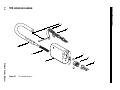
1
CREDITS/COPYRIGHT
Copyright © 1997–2004 Stanley Security Solutions, Inc. and Stanley Logistics, Inc. All
rights reserved. Printed in the United States of America.
Information in this document is subject to change without notice and does not
represent a commitment on the part of Stanley Security Solutions, Inc. The software
described in this document are furnished under a license agreement or nondisclosure
agreement.
This publication is intended to be an accurate description and set of instructions
pertaining to its subject matter. However, as with any publication of this complexity,
errors or omissions are possible. Please call your BEST® distributor or Stanley Security
Solutions, Inc., Best Access Systems at (317) 849-2250 if you see any errors or have any
questions. No part of this manual and/or databases may be reproduced or transmitted
in any form or by any means, electronic or mechanical, including photocopying,
recording, or information storage and retrieval systems, for any purpose, without the
express written permission of Stanley Security Solutions, Inc.
This document is distributed as is, without warranty of any kind, either express or
implied, respecting the contents of this book, including but not limited to implied
warranties for the publication’s quality, performance, merchantability, or fitness for any
particular purpose. Neither Stanley Security Solutions, Inc., nor its dealers or
distributors shall be liable to the user or any other person or entity with respect to any
liability, loss, or damage caused or alleged to be caused directly or indirectly by this
publication.
Lubriplate is a registered trademark of Fiske Brothers Refining Company. Sargent is a
registered trademark of Sargent Manufacturing Co. Von Duprin is a registered
trademark of Von Duprin, Inc.
Written and designed by Best Access Systems and Avalon Group, Inc., Indianapolis,
Indiana.
T35525 Rev B 1796901 ER–7991–6 Oct 2004
CONTENTS
FIGURES
V
GETTING STARTED
1–1
Introduction 1–1
Certifications and standards 1–1
11B Padlock 1–1
21B, 41B Padlocks 1–1
Technical support 1–2
Support services 1–2
Telephone technical support 1–2
COMPONENT REPLACEMENT
2–1
11B exploded diagram 2–2
11B parts list 2–3
21B exploded diagram 2–4
21B parts list 2–5
21B shrouded exploded diagram 2–6
21B shrouded parts list 2–7
21JB exploded diagram 2–8
21JB parts list 2–9
41B exploded diagram 2–10
41B parts list 2–11
Miscellaneous parts 2–12
11B Frangible Shackle Kit parts list 2–13
Chains
parts list 2–13
Lubricant
parts list 2–13
Padlock Service Manual
iii
Contents
Function conversion 2–14
Disassembling and assembling padlocks 2–15
Disassembling the 11B, 21B, 21JB, and 41B Padlocks 2–15
Assembling the 11B, 21B, 21JB, and 41B Padlocks 2–16
Disassembling Lubricating padlock parts 2–19
INDEX A–1
iv
Padlock Service Manual
FIGURES
CONTENTS
FIGURES
GETTING STARTED
COMPONENT REPLACEMENT
11B exploded diagram
2–2
21B exploded diagram
2–4
21B shrouded exploded diagram
21JB exploded diagram
2–8
41B exploded diagram
2–10
11B Frangible Shackle Kit
Chains
2–6
2–12
2–12
Corrosion Free Lubricant
2–12
11B, 21B, and 41B throw members
2–14
Removing the core and throw member
Inserting the disassembly tool
2–15
2–15
Engaging and rotating the disassembly tool
Placing the shackle spring
2–16
2–16
Pushing the tumblers into position (side, cross–section view)
Inserting the locking cam (bottom view)
2–17
Pushing the locking cam into position (bottom view)
Installing the core and throw member
2–17
2–18
2–18
INDEX
Padlock Service Manual
v
Figures
vi
Padlock Service Manual
1
GETTING STARTED
INTRODUCTION
The B Series Padlock Service Manual contains
essential information to help you assemble, install,
and maintain your BEST padlocks. BEST recommends
that your lock maintenance personnel be thoroughly
familiar with the contents of this manual.
CERTIFICATIONS AND STANDARDS
All of the padlocks comply with ASTM F883 Grade 6
standards for option E.
11B Padlock
■
The steel shackle complies with ASTM F883
Grade 1 standards.
21B,
41B Padlocks
■
The steel shackle complies with ASTM F883
Grade 4 standards.
The 21B XSPL shackle complies with ASTM F883
Grade 6 standards for shackle cutting force.
■
Padlock Service Manual
1–1
Getting Started
TECHNICAL SUPPORT
Support
services
When you have a question about a B Series Padlock, your first resource
for help is the B Series Padlock Service Manual. If you cannot find a
satisfactory answer, contact your local BEST representative.
Telephone
technical
support
A factory-trained Certified Product Specialist (CPS) is available in your
area whenever you need help. Before you call, however, please make
sure you are where the padlock is, and that you are prepared to give the
following information:
■ what happened and what you were doing when the question arose
■ what you have done so far to answer the question.
Best Access Systems Representatives provide telephone technical
support for all B Series products. You may locate the representative
nearest you by calling (317) 849-2250 Monday through Friday, between
7:00 a.m. and 4:00 p.m. eastern standard time; or visit the web page,
www.bestaccess.com.
1–2
Padlock Service Manual
2
COMPONENT REPLACEMENT
The following pages contain exploded diagrams and
parts lists for all B Series Padlocks. The diagrams
include all field serviceable parts. Use the diagrams
and parts lists to find the part numbers that you
need. For more information about ordering parts, see
your B Series Catalog. This chapter also contains
function conversion information, instructions for
disassembling and assembling the padlocks, and
instructions for lubricating the padlocks.
Padlock Service Manual
2–1
4
Component Replacement
2–2
11B EXPLODED DIAGRAM
5
6
1
2
7
8
3
Padlock Service Manual
Figure 2.1
11B exploded diagram
9
Component Replacement
11B parts list
Refer to Figure 2.1 and the table below to find the part that you need.
Item
Part No. Qty.
Description
1
C26195
1
Stainless steel shackle for 3/4″ opening*
not shown
C26197
1
Stainless steel shackle for 1 1/2″ opening
not shown
C26199
1
Stainless steel shackle for 2″ opening
not shown
C26203
1
Stainless steel shackle for 4″ opening
not shown
C26194
1
Bronze shackle for 3/4″ opening
not shown
C26196
1
Bronze shackle for 1 1/2″ opening
not shown
C26198
1
Bronze shackle for 2″ opening
not shown
C26202
1
Bronze shackle for 4″ opening
not shown
C26250
1
Frangible shackle for 1 1/2″ opening
not shown
C26249
1
Frangible shackle for 4″ opening
2
A26193
1
Shackle spring
3
C26179
1
Standard case
A26265
1
Double lockout case for chain (indicated by dashed
lines)
C26175
1
Double lockout case (indicated by dashed lines)
A26252
1
Case for chain
4
A26255
1
Clevis rivet
5
B26261
1
Clevis
6
A21417
1
not shown
A21420
1
M1 Chain [there is no distinction between length
and bulk for M1 chain like the M5 chain]
M5 Chain – 9 inch†
7
A26192
2
Tumbler
8
B26187
1
Locking cam assembly
9
A26177
1
Key retained throw member
not shown
A26185
Non-key retained throw member
not shown
A06831
1
‡
not shown
B70146
1
Spacer (For 6-pin or 5-pin core only)
Colored O.S.H.A. cover**
not shown
C26517
1
Weather cover
* The length of the shackle opening is measured from the top of the case to the inside of
the shackle when the padlock is locked.
† To order M5 bulk chain use part number A23121 and specify the length.
‡ One needed for 6-pin core. Two needed for 5-pin core.
** When ordering the O.S.H.A. cover, indicate color: red; yellow; blue; black; orange; or
green.
Padlock Service Manual
2–3
Component Replacement
2–4
21B EXPLODED DIAGRAM
4
5
6
1
2
7
8
Padlock Service Manual
3
Figure 2.2
21B exploded diagram
9
Component Replacement
21B parts list
Refer to Figure 2.2 and the table below to find the part that you need.
Item
Part No. Qty.
Description
1
not shown
not shown
not shown
not shown
not shown
not shown
not shown
not shown
not shown
not shown
not shown
C26211
C26213
C26215
C26219
C26210
C26212
C26214
C26218
C26540
C26541
C26542
C26543
1
1
1
1
1
1
1
1
1
1
1
1
2
A26193
1
Stainless steel shackle for 3/4″ opening*
Stainless steel shackle for 1 1/2″ opening
Stainless steel shackle for 2″ opening
Stainless steel shackle for 4″ opening
Bronze shackle for 3/4″ opening
Bronze shackle for 1 1/2″ opening
Bronze shackle for 2″ opening
Bronze shackle for 4″ opening
Cut-resistant shackle for 3/4″ opening
Cut-resistant shackle for 1 1/2″ opening
Cut-resistant shackle for 2″ opening
Cut-resistant shackle for 4″ opening
Shackle spring†
3
not shown
A26253
C26180
1
1
Case for chain
Standard case
4
A26256
1
Clevis rivet
5
B26261
1
Clevis
6
not shown
A21417
A23120
1
1
M1 Chain
M5 Chain – 9 inch‡
7
A26192
2
Tumbler
8
B26187
1
Locking cam assembly
9
not shown
A26177
A26185
Key retained throw member
Non-key retained throw member
not shown
A06831
1
1
**
not shown
B70147
1
Spacer (For 6-pin or 5-pin core only)
Colored O.S.H.A. cover††
not shown
C26518
1
Weather cover
not shown
C81131
1
Shroud
not shown
B81132
1
Shroud pin
* The length of the shackle opening is measured from the top of the case to the inside
of the shackle when the padlock is locked.
† Not needed for 21B shrouded.
‡ To order M5 bulk chain use part number A23121 and specify the length.
** One needed for 6-pin core. Two needed for 5-pin core.
†† When ordering the O.S.H.A. cover, indicate color: red; yellow; blue; black; orange; or
green.
Padlock Service Manual
2–5
Component Replacement
2–6
21B SHROUDED EXPLODED DIAGRAM
4
8
1
5
2
6
7
Padlock Service Manual
3
Figure 2.3
21B shrouded exploded diagram
Component Replacement
21B shrouded
parts list
Refer to Figure 2.3 and the table below to find the part that you need.
Item
Part No. Qty.
Description
1
C81133
1
Cut-resistant shackle
2
C81131
1
Shroud
3
A26268
1
Case
4
A26257
1
Clevis rivet
5
A26192
2
Tumbler
6
B26187
1
Locking cam assembly
7
not shown
A26177
A26185
1
1
Key retained throw member
Non-key retained throw member
8
A81136
Rubber spacer
not shown
A06831
1
*
Spacer (For 6-pin or 5-pin core only)
* One needed for 6-pin core. Two needed for 5-pin core.
Padlock Service Manual
2–7
Component Replacement
2–8
21JB EXPLODED DIAGRAM
1
4
2
5
Padlock Service Manual
6
3
Figure 2.4
21JB exploded diagram
Component Replacement
21JB parts list
Refer to Figure 2.4 and the table below to find the part that you need.
Item
Part No. Qty.
Description
1
B26209* 1
Cable assembly
2
A26193
1
Shackle spring
3
C26180
1
Standard case
4
B26289
1
Locking cam assembly
5
A26192
2
Tumbler
6
A26177
Key retained throw member
not shown
A06831
1
†
Spacer (For 6-pin or 5-pin core only)
* The cable assembly number is determined by the length of the cable ordered. When
ordering, indicate number B26209 followed by a dash and the length of the cable in
inches.
† One needed for 6-pin core. Two needed for 5-pin core.
Padlock Service Manual
2–9
4
Component Replacement
2–10
41B EXPLODED DIAGRAM
5
6
1
2
7
8
Padlock Service Manual
3
Figure 2.5
41B exploded diagram
9
Component Replacement
41B parts list
Refer to Figure 2.5 and the table below to find the part that you need.
Item
Part No. Qty.
1
not shown
not shown
not shown
not shown
not shown
not shown
not shown
not shown
not shown
not shown
not shown
C26227
C26229
C26231
C26235
C26226
C26228
C26230
C26234
C26544
C26545
C26546
C26547
1
1
1
1
1
1
1
1
1
1
1
1
Description
Stainless steel shackle for 3/4″ opening*
Stainless steel shackle for 1 1/2″ opening
Stainless steel shackle for 2″ opening
Stainless steel shackle for 4″ opening
Bronze shackle for 3/4″ opening
Bronze shackle for 1 1/2″ opening
Bronze shackle for 2″ opening
Bronze shackle for 4″ opening
Cut-resistant shackle for 3/4″ opening
Cut-resistant shackle for 1 1/2″ opening
Cut-resistant shackle for 2″ opening
Cut-resistant shackle for 4″ opening
2
A26193
1
Shackle spring
3 not shown
not shown
not shown
not shown
not shown
C26262
A26254
A26266
C26161
C26181
1
1
1
1
1
Cutaway padlock case
Case for clevis and chain
Car seal case for chain
Car seal case
Standard case
4
A26257
1
Clevis rivet
5
B26261
1
Clevis
6
not shown
A21417
A23120
1
1
M1 Chain
M5 Chain – 9 inch†
7
A26192
2
Tumbler
8
B26187
1
Locking cam assembly
9
not shown
A26177
A26185
Key retained throw member
Non-key retained throw member
not shown
A06831
1
1
‡
not shown
B70148
1
Spacer (For 6-pin or 5-pin core only)
Colored O.S.H.A. cover**
not shown
C26519
1
Weather cover
* The length of the shackle opening is measured from the top of the case to the inside of
the shackle when the padlock is locked.
† To order M5 bulk chain use part number A23121 and specify the length.
‡ One needed for 6-pin core. Two needed for 5-pin core.
** When ordering the O.S.H.A. cover, indicate color: red; yellow; blue; black; orange; or
green.
Padlock Service Manual
2–11
Component Replacement
MISCELLANEOUS PARTS
1
3
2
Figure 2.6
11B Frangible Shackle Kit
1
2
Figure 2.7
Chains
1
Figure 2.8
2–12
Corrosion Free Lubricant
Padlock Service Manual
Component Replacement
11B Frangible
Shackle Kit
parts list
Refer to Figure 2.6 and the table below to find the part that you need.
Item*
Part. No. Qty.
Description
1
C26249
3
Shackle
2
A26193
3
Shackle spring
3
A26270
1
Disassembly tool
* These parts can be ordered as a kit by indicating part number is B26290.
Chains
parts list
Lubricant
parts list
Padlock Service Manual
Refer to Figure 2.7 and the table below to find the part that you need.
Item
Part No. Description
1
A21417
M1 Bronze chain
2
A23120
M5 Galvanized steel chain with gray plastic polycoat covering –
9 inch (10 links)
not
A23121
shown
M5 Galvanized steel chain with gray plastic polycoat covering –
bulk; specify length
Refer to Figure 2.8 and the table below to find the part that you need.
Item
Nomenclature Description
1
BD660
Corrosion Free Formula 8000 Industrial Lubricant
2–13
Component Replacement
FUNCTION CONVERSION
To convert the function of 11B, 21B, and 41B Padlocks, change the
throw member:
■
■
to convert to key retained, order part number A26177.
to convert to non-key retained, order part number A26185.
Figure 2.9 shows the available throw members. To remove and replace
the throw member, see Disassembling the 11B, 21B, 21JB, and 41B
Padlocks on page 2-15 and Assembling the 11B, 21B, 21JB, and 41B
Padlocks on page 2-16.
Key retained
Figure 2.9
2–14
Non-key retained
11B, 21B, and 41B throw members
Padlock Service Manual
Component Replacement
DISASSEMBLING AND ASSEMBLING PADLOCKS
Disassembling
the 11B, 21B,
21JB, and 41B
Padlocks
To disassemble the 11B, 21B, 21JB, and 41B Padlocks, perform the
following steps:
1. If there is a dust cover assembly on the lock, unscrew the screw and
remove the dust cover with the rubber seal and dust cover hinge.
2. With the padlock in the locked position, insert the control key into
the core and rotate the key to the right. Remove the core and throw
member from the core receptacle, as shown in Figure 2.10.
Core receptacle
Throw member
Core
Figure 2.10 Removing the core and throw member
3. With the padlock in the locked position, insert the disassembly tool
into the bottom core receptacle lobe, as shown in Figure 2.11, until
it touches the locking cam.
Note: The assembly tool guidepost allows the tool to be inserted
only one way.
When performing Step 3, be sure to hold the shackle. The shackle
could eject from the case while you’re removing the locking cam.
Caution
Bottom core
receptacle lobe
Disassembly tool
Figure 2.11 Inserting the disassembly tool
Padlock Service Manual
2–15
Component Replacement
4. Press in on the disassembly tool and turn it counterclockwise until it
is engaged between the locking cam assembly and the spring
positioner, as shown in Figure 2.12. Gently pull the tool to remove
the locking cam assembly from the core receptacle.
Locking cam
assembly
Disassembly tool
Figure 2.12 Engaging and rotating the disassembly tool
5. Remove the shackle, shackle spring, and tumblers.
Assembling the
11B, 21B, 21JB,
and 41B
Padlocks
To assemble the 11B, 21B, 21JB, and 41B Padlocks, perform the
following steps:
1. Place the shackle spring on the shackle spring post, as shown in
Figure 2.13.
Shackle spring post
Shackle spring
Figure 2.13 Placing the shackle spring
2. Insert the long shackle leg and shackle spring into the long shackle
hole, and the short shackle leg into the short shackle hole. Hold the
shackle in the locked position.
2–16
Padlock Service Manual
Component Replacement
3. Turn the case upside-down. Drop the tumblers into the core
receptacle and push the tumblers into the case cross holes, as
shown in Figure 2.14.
Core receptacle
Tumbler in
case cross hole
Tumbler in
case cross hole
Figure 2.14 Pushing the tumblers into position (side, cross–section view)
4. Insert the locking cam into the bottom core receptacle lobe so that
the round tip of the spring positioner is pointed toward the top core
receptacle lobe, as shown in Figure 2.15.
Top core
receptacle lobe
Round tip of the
spring positioner
Figure 2.15 Inserting the locking cam (bottom view)
Padlock Service Manual
2–17
Component Replacement
5. Using a punch or screwdriver, push on the round tip of the spring
positioner until the locking cam snaps clockwise into the slot, as
shown in Figure 2.16.
Caution
If the locking cam doesn’t seat fully, the tumblers may have rolled out
of position. Remove the locking cam and reposition the tumblers
before continuing.
Round tip of the
spring positioner
Figure 2.16 Pushing the locking cam into position (bottom view)
6. With the throw member’s recess on the same side as the core lug,
insert the throw member into the core, as shown in Figure 2.17.
With the control key in the core, insert the core with the throw
member into the core hole. Turn the control key to the left and
remove it.
Note: If the throw member is not installed properly, the core cannot
be installed.
Core lug
Recess on the key
retained throw member
Recess on the non-key
retained throw member
Figure 2.17 Installing the core and throw member
7. If there is a dust cover assembly for the lock, position the dust cover
so that the lip faces upwards. Position the rubber seal under the
dust cover and push the button on the rubber seal through the
opening in the dust cover.
2–18
Padlock Service Manual
Component Replacement
Disassembling
Lubricating
padlock parts
Apply one quick spray of BD660 Corrosion Free Formula 8000
Industrial Lubricant in both shackle holes every six months. The shackle
can be in either the locked or unlocked position. It is not necessary to
disassemble the padlock in order to lubricate it.
Note: Lubricate more often if the padlock is used frequently or is located
in a corrosive environment.
Padlock Service Manual
2–19
Component Replacement
2–20
Padlock Service Manual
A
INDEX
Numerics
installing core in 2–18
installing dust cover in 2–18
installing locking cam assembly in 2–17
installing shackle in 2–16
installing throw member in 2–18
installing tumblers in 2–17
part numbers for 2–9
removing core from 2–15
removing dust cover from 2–15
removing locking cam assembly from
2–15
removing shackle from 2–16
removing throw member from 2–15
removing tumblers from 2–16
11B
exploded diagram 2–2
installing core in 2–18
installing dust cover in 2–18
installing locking cam assembly in 2–17
installing shackle in 2–16
installing throw member in 2–18
installing tumblers in 2–17
part numbers for 2–3
removing core from 2–15
removing dust cover from 2–15
removing locking cam assembly from
2–15
removing shackle from 2–16
removing throw member from 2–15
removing tumblers from 2–16
41B
exploded diagram 2–10
installing core in 2–18
installing dust cover in 2–18
installing locking cam assembly in 2–17
installing shackle in 2–16
installing throw member in 2–18
installing tumblers in 2–17
part numbers for 2–11
removing core from 2–15
removing dust cover from 2–15
removing locking cam assembly from
2–15
removing shackle from 2–16
removing throw member from 2–15
removing tumblers from 2–16
21B
exploded diagram 2–4, 2–6
installing core in 2–18
installing dust cover in 2–18
installing locking cam assembly in 2–17
installing shackle in 2–16
installing throw member in 2–18
installing tumblers in 2–17
part numbers for 2–5, 2–7
removing core from 2–15
removing dust cover from 2–15
removing locking cam assembly from
2–15
removing shackle from 2–16
removing throw member from 2–15
removing tumblers from 2–16
21JB
exploded diagram 2–8
Padlock Service Manual
A
assembling
11B, 21B, 21JB, 41B 2–16
A-1
Index
C
L
cable assembly 2–9
case
part numbers for 2–9, 2–11
certifications and standards 1–1
chain
part numbers for 2–3, 2–5,
2–11, 2–13
clevis
part numbers for 2–3, 2–5,
2–11
clevis rivet
part numbers for 2–3, 2–5, 2–7,
2–11
cut-resistant shackle
part numbers for 2–7
locking cam assembly
part numbers for 2–3, 2–5, 2–7,
2–9, 2–11
lubricant
part number for 2–13
lubricating padlock parts 2–19
D
diagrams, exploded
for 11B 2–2
for 21B 2–4, 2–6
for 21JB 2–8
for 41B 2–10
disassembling
11B, 21B, 21JB, 41B 2–15
disassembly tool
part number for 2–13
using 2–15
drawings of parts
for 11B 2–2
for 21B 2–4, 2–6
for 21JB 2–8
for 41B 2–10
for chains 2–12
for frangible shackle kit 2–12
for lubricant 2–12
E
exploded diagrams
for 11B 2–2
for 21B 2–4, 2–6
for 21JB 2–8
for 41B 2–10
F
frangible shackle 2–13
frangible shackle kit 2–13
function conversion 2–14
K
key retained function 2–14
A-2
N
non-key retained function 2–14
numbers, for parts
11B 2–3
21B 2–5, 2–7
21JB 2–9
41B 2–11
chains 2–13
frangible shackle kit 2–13
lubricant 2–13
support, technical 1–2
T
technical support 1–2
throw member
and function conversion 2–14
part numbers for 2–3, 2–5, 2–7,
2–9, 2–11
tumbler
part numbers for 2–3, 2–5, 2–7,
2–9, 2–11
P
part numbers
for 11B 2–3
for 21B 2–5, 2–7
for 21JB 2–9
for 41B 2–11
for chains 2–13
for frangible shackle kit 2–13
for lubricant 2–13
parts drawings
for 11B 2–2
for 21B 2–4, 2–6
for 21JB 2–8
for 41B 2–10
for chains 2–12
for frangible shackle kit 2–12
for lubricant 2–12
R
rubber spacer
part numbers for 2–7
rust prevention 2–19
S
shackle
part numbers for 2–3, 2–11
shackle spring
part numbers for 2–3, 2–5, 2–9,
2–11, 2–13
shroud
part numbers for 2–7
spacer
part number for 2–3, 2–5, 2–7,
2–9, 2–11
Padlock Service Manual