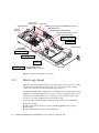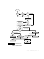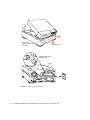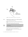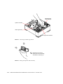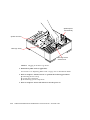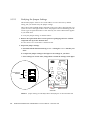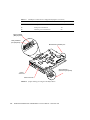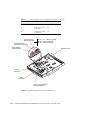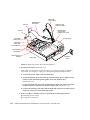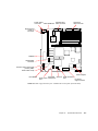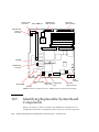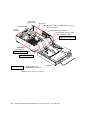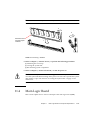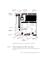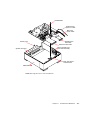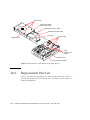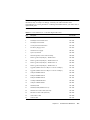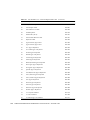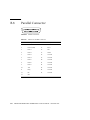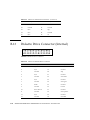
1
SPARCclassic/SPARCclassic
X/SPARCstation LX Service
Manual
Sun Microsystems Computer Company
A Sun Microsystems, Inc. Business
901 San Antonio Road Palo Alto, CA 94303-4900 USA
650 960-1300
fax 650 969-9131
Part No.: 801-2176-13
Revision A, November 1993
Send comments about this document to: [email protected]
1997 Sun Microsystems, Inc., 901 San Antonio Road, Palo Alto, California 94303-4900 U.S.A.
All rights reserved.
This product or document is protected by copyright and distributed under licenses restricting its use, copying, distribution, and decompilation.
No part of this product or document may be reproduced in any form by any means without prior written authorization of Sun and its licensors,
if any.
Portions of this product may be derived from the UNIX® system, licensed from Novell, Inc., and from the Berkeley 4.3 BSD system, licensed
from the University of California. UNIX is a registered trademark in the United States and in other countries and is exclusively licensed by
X/Open Company Ltd. Third-party software, including font technology in this product, is protected by copyright and licensed from Sun’s
suppliers. RESTRICTED RIGHTS: Use, duplication, or disclosure by the U.S. Government is subject to restrictions of FAR 52.227-14(g)(2)(6/87)
and FAR 52.227-19(6/87), or DFAR 252.227-7015(b)(6/95) and DFAR 227.7202-3(a).
Sun, Sun Microsystems, the Sun logo, and Solaris are trademarks or registered trademarks of Sun Microsystems, Inc. in the United States and in
other countries. All SPARC trademarks are used under license and are trademarks or registered trademarks of SPARC International, Inc. in the
United States and in other countries. Products bearing SPARC trademarks are based upon an architecture developed by Sun Microsystems, Inc.
The OPEN LOOK® and Sun™ Graphical User Interfaces were developed by Sun Microsystems, Inc. for its users and licensees. Sun
acknowledges the pioneering efforts of Xerox Corporation in researching and developing the concept of visual or graphical user interfaces for
the computer industry. Sun holds a nonexclusive license from Xerox to the Xerox Graphical User Interface, which license also covers Sun’s
licensees who implement OPEN LOOK GUIs and otherwise comply with Sun’s written license agreements.
THIS PUBLICATION IS PROVIDED “AS IS” WITHOUT WARRANTY OF ANY KIND, EITHER EXPRESS OR IMPLIED, INCLUDING, BUT
NOT LIMITED TO, THE IMPLIED WARRANTIES OF MERCHANTABILITY, FITNESS FOR A PARTICULAR PURPOSE, OR NONINFRINGEMENT.
Copyright 1997 Sun Microsystems, Inc., 901 San Antonio Road, Palo Alto, Californie 94303-4900 U.S.A. Tous droits réservés.
Ce produit ou document est protégé par un copyright et distribué avec des licences qui en restreignent l’utilisation, la copie et la décompilation.
Aucune partie de ce produit ou de sa documentation associée ne peut être reproduite sous aucune forme, par quelque moyen que ce soit, sans
l’autorisation préalable et écrite de Sun et de ses bailleurs de licence, s’il y en a.
Des parties de ce produit pourront être derivées du système UNIX® licencié par Novell, Inc. et du système Berkeley 4.3 BSD licencié par
l’Université de Californie. UNIX est une marque enregistrée aux Etats-Unis et dans d’autres pays, et licenciée exclusivement par X/Open
Company Ltd. Le logiciel détenu par des tiers, et qui comprend la technologie relative aux polices de caractères, est protégé par un copyright et
licencié par des fournisseurs de Sun.
Sun, Sun Microsystems, le logo Sun, et Solaris sont des marques déposées ou enregistrées de Sun Microsystems, Inc. aux Etats-Unis et dans
d’autres pays. Toutes les marques SPARC, utilisées sous licence, sont des marques déposées ou enregistrées de SPARC International, Inc. aux
Etats-Unis et dans d’autres pays. Les produits portant les marques SPARC sont basés sur une architecture développée par Sun Microsystems,
Inc.
Les utilisateurs d’interfaces graphiques OPEN LOOK® et Sun™ ont été développés de Sun Microsystems, Inc. pour ses utilisateurs et licenciés.
Sun reconnaît les efforts de pionniers de Xerox Corporation pour la recherche et le développement du concept des interfaces d’utilisation
visuelle ou graphique pour l’industrie de l’informatique. Sun détient une licence non exclusive de Xerox sur l’interface d’utilisation graphique,
cette licence couvrant aussi les licenciés de Sun qui mettent en place les utilisateurs d’interfaces graphiques OPEN LOOK et qui en outre se
conforment aux licences écrites de Sun.
CETTE PUBLICATION EST FOURNIE "EN L’ETAT" SANS GARANTIE D’AUCUNE SORTE, NI EXPRESSE NI IMPLICITE, Y COMPRIS, ET
SANS QUE CETTE LISTE NE SOIT LIMITATIVE, DES GARANTIES CONCERNANT LA VALEUR MARCHANDE, L’APTITUDE DES
PRODUITS A REPONDRE A UNE UTILISATION PARTICULIERE OU LE FAIT QU’ILS NE SOIENT PAS CONTREFAISANTS DE PRODUITS
DE TIERS.
Please
Recycle
Contents
Preface
1.
Product Description
1.1
2.
xv
System Unit
1-1
1-1
1.1.1
Main Logic Board
1-4
1.1.2
Memory Modules
1-5
1.1.2.1
Video SIMM
1.1.2.2
SBus Cards
1-5
1-5
1.1.3
Nonvolatile RAM (NVRAM)
1.1.4
Internal Hard Disk Drive
1.1.5
Internal Diskette Drive
1.1.6
Power Supply
1-7
1-7
1-7
1.2
Monitors, Keyboard, and Mouse
1.3
External Storage Devices
1-8
1.4
System Interconnections
1-8
Troubleshooting Overview
1-6
1-7
2-1
2.1
Default Boot Mode
2-1
2.2
Boot PROM Diagnostics
2.3
Low-Level POST Code
2.4
Diagnostic Tools and When to Use Them
2-1
2-4
2-7
Contents
iii
3.
2.5
Power-On Self-Test
2.6
Selected On-Board Tests
2.7
Sundiag System Exerciser
2.8
Forth Toolkit
2.9
SunDiagnostic Executive
2-10
3-1
Power-On Self-Test (POST)
3.2
Normal Mode
3.3
Full Diagnostic Mode
3.4
Abbreviated Diagnostic Mode
3-1
3-4
3-4
3-4
Setting Up a tip Connection to Another Workstation
3.5
Tests the POST Runs
3.6
POST Error Messages
3.7
Status Lights (LEDs) and Indicators
3-8
3-8
4-1
4.1
No Video Output on the System Monitor
4.2
Power-On Does Not Succeed
4.4
4-2
4-2
4.2.1
Power Supply Test
4-3
4.2.2
System Board Test
4-5
Caps Lock Key Fails to Flash On and Off During
POST 4-5
Disk Drive Errors
4.3.1
3-5
3-6
Troubleshooting Procedures
4.3
iv
2-9
3.1
4.2.2.1
5.
2-8
2-9
Power-On Self-Test (POST)
3.4.1
4.
2-8
4-6
Verifying the Built-In SCSI Controller
Determining Faulty DSIMM Locations
Safety and Tools Requirements
5.1
Safety Requirements
5.2
Symbols
5.3
System Precautions
4-6
4-7
5-1
5-1
5-2
5-3
SPARCclassic/SPARCclassic X/SPARCstation LX Service Manual • November 1993
5.4
6.
Power Off and On
6.1
6.2
7.
8.
5-3
6-1
Powering Off the System
6-1
6.1.1
Powering Off When the System Is Working Normally
6.1.2
Powering Off When the System Does Not Respond Normally
Powering On the System
Internal Access
7.2
Opening the System Unit
7-2
7.3
Attaching the Wrist Strap
7-3
7.4
Closing the System Unit
7.5
Reconnecting the External Cables
Major Subassemblies
8.3
Power Supply
9.1
7-1
7-4
7-7
8-1
8-1
8.1.1
Removing the Power Supply
8-1
8.1.2
Replacing the Power Supply
8-3
Speaker/Power LED Assembly
8-4
8.2.1
Removing the Speaker/Power LED Assembly
8-4
8.2.2
Replacing the Speaker/Power LED Assembly
8-6
System I/O Board
8-7
8.3.1
Removing the System I/O Board
8-7
8.3.2
Replacing the System I/O Board
8-12
Storage Devices
6-3
7-1
Disconnecting the External Cables
8.2
6-1
6-4
7.1
8.1
9.
Tools Required
9-1
Hard Disk Drive
9-1
9.1.1
Removing a Hard Disk Drive
9.1.2
Preparing a Hard Drive for Installation
9.1.2.1
9-2
Verifying the Jumper Settings
9-3
9-4
Contents
v
9.1.3
9.2
9.3
10.
11.
Disk Drive Bracket
9-13
9-15
9.2.1
Removing the Disk Drive Mounting Bracket
9-16
9.2.2
Replacing the Disk Drive Mounting Bracket
9-19
Diskette Drive
9-21
9.3.1
Removing the Diskette Drive
9-22
9.3.2
Replacing the Diskette Drive
9-23
System Board Overview
10-1
10.1
Before You Begin
10.2
Damage Prevention
10.3
Handling System Boards and Assemblies
10.4
Main Logic Board Layouts
10.5
Identifying Replaceable System Board Components
10-1
10-2
10-2
10-4
Main Logic Board and Component Replacement
11.1
11.2
11.3
11.4
vi
Installing a Hard Disk Drive
SBus Cards
10-6
11-1
11-1
11.1.1
Removing SBus Cards
11-1
11.1.2
Replacing SBus Cards
11-4
Video SIMM (VSIMM)
11-6
11.2.1
Removing the VSIMM
11-7
11.2.2
Replacing the VSIMM
11-9
DRAM Single In-line Memory Modules (DSIMMs)
11.3.1
DSIMM Configurations
11.3.2
Removing a DSIMM
11-13
11.3.3
Replacing a DSIMM
11-15
Main Logic Board
11-10
11-11
11-17
11.4.1
Main Logic Board Voltage Test Points
11.4.2
Before Replacing the Main Logic Board
11.4.3
Removing the Main Logic Board
11.4.4
Installing the New Main Logic Board
11-18
11-21
11-24
11-29
SPARCclassic/SPARCclassic X/SPARCstation LX Service Manual • November 1993
11.5
11.6
12.
Nonvolatile RAM (NVRAM)
11-31
11.5.1
Removing the NVRAM
11-31
11.5.2
Replacing the NVRAM
11-33
SPARCstation LX ISDN Jumper Settings
Illustrated Parts Breakdown
12-1
12.1
Illustrations of Selected CRUs
12.2
Replacement Part List
A. System Specifications
12-1
12-4
A-1
A.1
Input Power Requirements
A.2
Environmental Requirements
A.3
Physical Specifications
A.4
Regulatory Compliance
B. System Connectors
11-33
A-1
A-2
A-3
A-3
B-1
B.1
Attachment Unit Interface (AUI) Connector
B.2
Twisted-Pair Ethernet Connector
B.3
ISDN Terminal Endpoint Connector
B.4
ISDN Network Termination Connector
B.5
Keyboard/Mouse Connector
B.6
SCSI Connector (External)
B.7
Serial Connector
B.8
Parallel Connector
B.9
13W3 Video Connector
B.10
Audio Ports and Audio Module
B-3
B-4
B-5
B-6
B-8
B-9
B-9
B-9
Signals for the Audio Ports
B-10
B.11.1 Audio Line-Out Connector
B.11.2 Audio Line-In Connector
B.12
B-3
B-7
B.10.1 Audio Ports
B.11
B-2
SCSI Connector (Internal)
B-10
B-10
B-11
Contents
vii
B.13
Diskette Drive Connector (Internal)
B.14
SBus Connector (Internal)
B.15
Power Connector (Internal)
C. On-Board Diagnostics
C.1
C.2
B-13
B-14
C-1
Running the On-Board Diagnostics
C-1
C.1.1
Test <alias name>, Test <device path>
C.1.2
Test-all
C.1.3
Watch-clock
C.1.4
Watch-net, Watch-aui, Watch-tpe and Watch-net-all
C.1.5
Probe-scsi, Probe-scsi-all
C.1.6
Test-memory
C-3
C-4
C-4
C-7
C-7
Returning to the Monitor Prompt
Glossary
viii
B-12
C-8
Glossary-1
SPARCclassic/SPARCclassic X/SPARCstation LX Service Manual • November 1993
C-4
Figures
FIGURE 1-1
Front Panel of the SPARCclassic and SPARCstation LX System Units 1-2
FIGURE 1-2
Rear Panel of the System Unit
FIGURE 1-3
System Unit Internal Components 1-4
FIGURE 1-4
Typical DSIMM 1-5
FIGURE 1-5
Typical SBus Card
FIGURE 1-6
Connecting the Major System Components
FIGURE 2-1
Default Boot Mode
FIGURE 3-1
Arrangement of Type-5 Keyboard Diagnostic LEDs 3-2
FIGURE 3-2
SPARCstation System Banner
FIGURE 3-3
System Power LED on Front of System 3-8
FIGURE 3-4
Arrangement of the Type-5 Keyboard LEDs
FIGURE 4-1
Power Supply Connector
FIGURE 4-2
DSIMM Slot Locations
FIGURE 7-1
Opening the System Unit 7-3
FIGURE 7-2
Attaching the Wrist Strap 7-4
FIGURE 7-3
Closing the System Unit
FIGURE 7-4
Reconnecting System Components
FIGURE 8-1
Removing and Replacing the Power Supply 8-3
FIGURE 8-2
Removing and Replacing the Speaker/Power LED Assembly 8-6
1-3
1-6
1-9
2-3
3-3
3-9
4-4
4-8
7-6
7-7
Figures
ix
x
FIGURE 8-3
System I/O Board and Unit Bottom 8-8
FIGURE 8-4
Extracting the Main Logic Board
FIGURE 8-5
Raising the Speaker/LED Assembly 8-10
FIGURE 8-6
Removing and Replacing the Main Logic Board 8-11
FIGURE 8-7
Removing the System I/O Board 8-12
FIGURE 8-8
Plugging in the Main Logic Board
FIGURE 9-1
Hard Disk Drive in the Disk Drive Bracket 9-3
FIGURE 9-2
Jumper Settings for 207-Mbyte Drive With Jumpers on the Left-Hand Side 9-4
FIGURE 9-3
Jumper Settings for 207-Mbyte Drive With Jumpers on the Right-Hand Side
FIGURE 9-4
Jumper Settings for 424-Mbyte Drive
FIGURE 9-5
Jumper Settings for Conner 535-Mbyte Drive 9-7
FIGURE 9-6
Jumper Settings for Seagate 535-Mbyte Drive 9-8
FIGURE 9-7
Jumper Settings for 1.0-Gbyte Drive (Part 370-1546)
FIGURE 9-8
Jumper Settings for Seagate 1.0-Gbyte Drive
FIGURE 9-9
Jumper Settings for Connor 1.0-Gbyte Drive 9-12
FIGURE 9-10
Installing a Hard Disk Drive 9-14
FIGURE 9-11
Main Logic Board
FIGURE 9-12
Open View of System Unit
FIGURE 9-13
Removing the Disk Drive Mounting Bracket
FIGURE 9-14
Detail of Disk Drive Mounting Bracket 9-19
FIGURE 9-15
Replacing the Disk Drive Mounting Bracket 9-20
FIGURE 9-16
Disk Drive Mounting Bracket
FIGURE 10-1
Main Logic Board Layout—SPARCclassic/SPARCclassic X Systems 10-4
FIGURE 10-2
Main Logic Board Layout—SPARCstation LX System (Part 270-2233) 10-5
FIGURE 10-3
Main Logic Board Layout—SPARCstation LX System (Part 270-2474) 10-6
FIGURE 10-4
View of Open System Unit
FIGURE 11-1
Removing the SBus Card
FIGURE 11-2
SBus Slot Filler Panels
8-10
8-14
9-6
9-10
9-11
9-15
9-17
9-18
9-22
10-8
11-3
11-3
SPARCclassic/SPARCclassic X/SPARCstation LX Service Manual • November 1993
9-5
FIGURE 11-3
Positioning the SBus Card
FIGURE 11-4
Connecting the SBus Card 11-6
FIGURE 11-5
VSIMM Slot Location 11-8
FIGURE 11-6
Removing the VSIMM 11-9
FIGURE 11-7
Installing the VSIMM
FIGURE 11-8
Typical DSIMM 11-11
FIGURE 11-9
DSIMM Slot Locations
FIGURE 11-10
Removing a DSIMM 11-15
FIGURE 11-11
Installing a DSIMM
FIGURE 11-12
Main Logic Board Layout—SPARCclassic/SPARCclassic X
FIGURE 11-13
Main Logic Board Layout—SPARCstation LX (Part 270-2233)
11-20
FIGURE 11-14
Main Logic Board Layout—SPARCstation LX (Part 270-2474)
11-21
FIGURE 11-15
Extracting the Main Logic Board
FIGURE 11-16
Raising the Speaker/LED Assembly 11-27
FIGURE 11-17
Removing and Replacing the Main Logic Board 11-28
FIGURE 11-18
Plugging in the Main Logic Board
FIGURE 11-19
Locating the NVRAM 11-32
FIGURE 11-20
Removing the NVRAM 11-32
FIGURE 11-21
Default SPARCstation LX ISDN Jumper Settings 11-33
FIGURE 12-1
Exploded View of the Unit Top
FIGURE 12-2
Exploded View of the Unit Bottom 12-3
FIGURE 12-3
Exploded View of the Disk Drive Mounting Bracket 12-4
FIGURE B-1
Attachment Unit Interface (AUI) Connector
FIGURE B-2
Twisted-Pair Ethernet Connector
FIGURE B-3
ISDN Terminal Endpoint Connector
FIGURE B-4
ISDN Network Termination Connector
FIGURE B-5
Keyboard/Mouse Connector
FIGURE B-6
External SCSI Connector
11-5
11-10
11-12
11-17
11-19
11-27
11-30
12-2
B-2
B-3
B-3
B-4
B-5
B-6
Figures
xi
FIGURE B-7
Serial Connector B-7
FIGURE B-8
Parallel Connector B-8
FIGURE B-9
13W3 Video Connector B-9
FIGURE B-10
xii
Audio Ports B-10
FIGURE B-11
Audio Line-out Connector B-10
FIGURE B-12
Audio Line-in Connector B-10
FIGURE B-13
Internal SCSI Connector B-11
FIGURE B-14
Diskette Drive Connector
FIGURE B-15
SBus Connector
FIGURE B-16
Power Connector B-14
B-12
B-13
SPARCclassic/SPARCclassic X/SPARCstation LX Service Manual • November 1993
Tables
TABLE 2-1
NVRAM Parameters Used During POST and Boot Sequence
TABLE 2-2
Summary of Autoboot and Diagnostic Switch Parameters
TABLE 2-3
Diagnostic Tools
TABLE 2-4
On-Board Diagnostics
TABLE 3-1
Interpreting the Keyboard Diagnostic LEDs
TABLE 3-2
Listing of POST Tests
TABLE 4-1
Troubleshooting Tips
TABLE 4-2
Power Supply Connector Pin Assignments
TABLE 4-3
Troubleshooting Disk Drive Errors
TABLE 4-4
2-5
2-5
2-7
2-8
3-2
3-6
4-1
4-4
4-6
Physical Memory Address Ranges for 4-Mbyte and 16-Mbyte SIMMs
TABLE 4-5
Physical Memory Address Ranges for 1-Mbyte and 2-Mbyte SIMMs
TABLE 4-6
Determining the Defective DSIMM
TABLE 5-1
Safety Precautions
TABLE 9-1
535-Mbyte Conner Drive Configuration Jumpers
9-7
TABLE 9-2
535-Mbyte Seagate Drive Configuration Jumpers
9-9
TABLE 9-3
1.0-Gbyte Seagate Drive Configuration Jumpers
9-11
4-8
4-9
4-9
5-2
TABLE 9-4
1.0-Gbyte Conner Drive Configuration Jumpers 9-13
TABLE 10-1
Safety Precautions
TABLE 10-2
Acronyms for Components of the Main Logic Board 10-7
10-3
Tables
xiii
xiv
TABLE 11-1
Memory Configuration Matrix—SPARCclassic X Terminal
TABLE 11-2
Configuration Matrix for Memory Modules 11-13
TABLE 11-3
SPARCstation LX ISDN Jumper Settings
TABLE 12-1
Part Number List—Customer Replaceable Units
TABLE 12-2
Part Number List—Miscellaneous Items 12-7
TABLE 12-3
Part Number List—Related Hardware Documentation
TABLE A-1
Input Power Requirements and Power Dissipation
TABLE A-2
Environmental Requirements
TABLE A-3
Physical Specifications
TABLE A-4
Regulatory Compliance Information
TABLE B-1
Pinout for Attachment Unit Interface (AUI) Connector
TABLE B-2
Pinout for Twisted-Pair Ethernet Connector
TABLE B-3
Pinout for ISDN Terminal Endpoint Connector B-3
TABLE B-4
Pinout for ISDN Network Termination Connector B-4
TABLE B-5
Pinout for Keyboard/Mouse Connector B-5
TABLE B-6
Pinout for External SCSI Connector
TABLE B-7
Pinout for Serial Connector
TABLE B-8
Pinout for Parallel Connector
TABLE B-9
Pinout for 13W3 Video Connector B-9
TABLE B-10
Audio Ports B-10
TABLE B-11
Pinout for Internal SCSI Connector
B-11
TABLE B-12
Pinout for Diskette Drive Connector
B-12
TABLE B-13
Pinout for SBus Connector
B-13
TABLE B-14
Pinout for Power Connector
B-14
11-12
11-34
12-5
12-7
A-1
A-2
A-3
A-3
B-2
B-3
B-6
B-7
B-8
SPARCclassic/SPARCclassic X/SPARCstation LX Service Manual • November 1993
Preface
The SPARCclassic/SPARCclassic X/SPARCstation LX Service Manual describes how to:
■
■
Identify system problems by running diagnostic programs
Remove and replace customer replaceable units (CRUs)
This book is written for Sun Field Service representatives, original equipment
manufacturers (OEMs), value-added resellers (VARs), and other customers with selfmaintenance contracts.
Document Organization
This book is divided into seven parts. A table at the beginning of each part lists the
chapters, sections and their page numbers.
■
Part 1, “System Information,“ describes an overview of the SPARCclassic™/
SPARCclassic X/SPARCstation™ product line’s standard features, and its external
options.
■
Part 2, “Troubleshooting,“ provides a troubleshooting overview; explains how to
run the Power-On Self-Test (POST) and other system diagnostics; and gives
troubleshooting procedures for some frequently encountered problems.
■
Part 3, “Preparing for Service,“ explains safety requirements, the symbols used in
this book, the tools required for replacing customer replaceable units, and how to
shut down, power off, and power on the system.
■
Part 4, “Subassembly Removal and Replacement,“ describes how to open and
close the system, attach and remove a wrist strap, and remove and replace
subassemblies.
■
Part 5, “System Board,“ provides an overview of the system board, and describes
how to remove and replace the system board, replaceable parts, and components
on the system board.
xv
■
Part 6, “Illustrated Parts Breakdown,“ provides illustrations of the major
replaceable parts and lists part numbers.
■
Part 7, “Appendixes, Glossary, and Index,“ defines physical, electrical, and
environmental specifications; lists connector pinouts and signal descriptions;
explains how to run selected on-board diagnostics; and provides a glossary of
technical terms, and an index.
What Typographic Changes and
Symbols Mean
The following table describes the type changes and symbols used in this book.
TABLE P-1
Typographic Conventions
Typeface or
Symbol
Meaning
Example
AaBbCc123
The names of commands, files,
and directories; on-screen
computer output
Edit your .login file.
Use ls -a to list all files.
system% You have mail.
Return
In text, key names are capitalized
Press the Return key.
Stop-a
Press and hold the Stop key, then
type the second character
Press Stop-a
AaBbCc123
What you type, contrasted with
on-screen computer output
system% su
Password:
AaBbCc123
Command-line placeholder:
replace with a real name or value
To delete a file, type rm filename.
AaBbCc123
Book titles, new words or terms,
or emphasized words
Read Chapter 6 in User’s Guide.
These are called class options.
You must be root to do this.
Code samples are included in boxes and may display the following:
xvi
%
UNIX C shell prompt
system%
$
UNIX Bourne and Korn shell
prompt
UNIX Bourne and Korn shell
prompt
SPARCclassic/SPARCclassic X/SPARCstation LX Service Manual • November 1993
TABLE P-1
Typographic Conventions (Continued)
Typeface or
Symbol
Meaning
Example
#
Superuser prompt, all shells
Superuser prompt, all shells
Mouse buttons are referred to in
this way:
Mouse
Buttons
SELECT
ADJUST
MENU
Related Books
The following books provide additional information, and are occasionally referenced
in this manual:
■
Open Boot Command Summary provides quick-reference information about the
various functions of the Open Boot PROM.
■
Open Boot Command Reference provides information about advanced functions of
the Open Boot PROM.
■
Sundiag User’s Guide covers information about Sundiag, a system exerciser that
runs under the SunOS™ operating system. Sundiag displays real-time use of
system resources and peripherals.
■
Sundiag User’s Guide—Addendum for SMCC Hardware covers Sundiag topics that
are specific to SPARCstation systems.
■
Desktop SPARC Hardware Owner’s Guide provides step-by-step instructions on how
to install the system’s hardware and software.
■
Using a SPARCclassic X Terminal contains instructions on how to install the
SPARCclassic X hardware.
■
Installing SPARCclassic/SPARCclassic X/SPARCstation LX SIMMs provides step-bystep information on how to install DSIMMs and VSIMMs in these systems.
xvii
■
Desktop Storage Pack Installation & Operation Manual explains how to install a
Desktop Backup Pack, Desktop Disk Pack, or Desktop SunCD™ Pack.
■
Desktop Storage Module Installation & User’s Guide explains how to install and
daisy-chain Desktop Storage Modules.
■
SunDiagnostic Executive User’s Guide for SPARCstations explains how to run
extensive, configurable tests that are independent of the operating system you
use. The SunDiagnostic Executive is the tool of choice when you need thorough
diagnostics. With the SunDiagnostic Executive, you can determine which
customer replaceable unit needs to be replaced.
■
Sun ISDN-BRI/SBI Hardware Configuration Guide explains about configuring ISDN
jumpers.
Notes, Cautions, and Warnings
Caution – Improper handling by unqualified personnel can cause serious damage
to this equipment. Unqualified personnel who tamper with this equipment may be
held liable for any resultant damage to the equipment.
Individuals who remove any outer panels to access this equipment must observe all
safety precautions and ensure compliance with skill level requirements, certification,
and all applicable local and national laws.
Procedures contained in this document must be performed by qualified Field
Service-trained maintenance providers.
Note – Before you begin, carefully read each of the procedures in this manual. If
you have not performed similar operations on comparable equipment,
do not attempt to perform these procedures.
xviii
SPARCclassic/SPARCclassic X/SPARCstation LX Service Manual • November 1993
CHAPTER
1
Product Description
This chapter presents an overview of the major components of the SPARCclassic,
SPARCstation LX systems, and the SPARCclassic X terminal. Acquaint yourself with
the overview before servicing and maintaining the hardware for these products.
■
■
■
■
Section 1.1
Section 1.2
Section 1.3
Section 1.4
“System Unit”
“Monitors, Keyboard, and Mouse”
“External Storage Devices”
“System Interconnections”
The SPARCclassic or the SPARCstation LX systems also can have an external storage
device or other small computer system interface (SCSI), serial, or parallel port
devices attached. The SPARCclassic X terminal software does not currently support
external devices.
1.1
System Unit
The heart of the SPARCclassic and SPARCstation LX systems is the system unit,
which contains the following components:
■
■
■
■
Main logic board (MLB)
Internal hard disk drive
Internal diskette drive (optional)
Power supply
FIGURE 1-1 and FIGURE 1-2 show the front and rear panels of the system unit.
1-1
Diskette drive (optional)
System power LED
FIGURE 1-1
Front Panel of the SPARCclassic and SPARCstation LX System Units
The SPARCclassic X terminal chassis looks identical to the chassis shown above,
except that the components on the list below are either not available or are inactive,
and are consequently covered by connector covers:
■
■
■
■
Diskette drive slot
SCSI port
Audio port
Parallel port
Internally, the SPARCclassic X terminal differs from the basic SPARCclassic system
by the absence of the disk drive and diskette drive. The annotations to FIGURE 1-2
and FIGURE 1-3 indicate the differences among the SPARCclassic system, the
SPARCstation LX system, and the SPARCclassic X terminal.
1-2
SPARCclassic/SPARCclassic X/SPARCstation LX Service Manual • November 1993
Lock block
Courtesy AC power outlet
System unit AC power receptacle
AC power switch
SBus card
connector openings
ISDN network
termination port *
ISDN terminal
endpoint port *
Twisted-pair
Ethernet port
TP
Keyboard
port
Serial
Audio
Audio 13W3 video SCSI
ports A/B input jack output jackport (monitor) port
Parallel
port
AUI/Audio port *
A B
= Inactive and covered on the
SPARCclassic X terminal
FIGURE 1-2
Note: Shaded items on
SPARCstation LX only
Rear Panel of the System Unit
Chapter 1
Product Description
1-3
SBus card
(system option)
SBus slots
UNIT BOTTOM
VSIMM module (option on SPARCstation LX only)
Main logic board
Speaker/Power LED assembly
Keyboard soft power-on cable
Main logic power cable
System
I/O board
Diskette drive data cable
Diskette drive
Power supply
DSIMMs
(fully populated)
Hard drive data cable
Hard drive power cable
Hard drive
= Not applicable to the
SPARCclassic X terminal
FIGURE 1-3
1.1.1
UNIT TOP
System Unit Internal Components
Main Logic Board
The main logic board (MLB) resides in the bottom half of the system unit. It plugs
into the system input/output (I/O) board, which provides all of the external
connectors to the system unit’s back panel (see FIGURE 1-2).
The different SPARCclassic/SPARCclassic X/SPARCstation LX MLB layouts are in
Chapter 10 “System Board Overview. FIGURE 10-1 shows a simplified layout of the
SPARCclassic and the SPARCclassic X main logic board, while FIGURE 10-2 and
FIGURE 10-3 show the SPARCstation LX main logic boards.
Customer replaceable units (CRUs) residing on the main logic board include:
■
■
■
■
1-4
Memory modules
Video single in-line memory modules (VSIMMs) (SPARCstation LX only)
SBus cards
Nonvolatile random access memory (NVRAM)
SPARCclassic/SPARCclassic X/SPARCstation LX Service Manual • November 1993
1.1.2
Memory Modules
SPARCclassic and SPARCstation LX system units come equipped with at least
16 megabytes of dynamic random access memory (DRAM), expandable to 96
megabytes. The X terminal comes with either 4 or 8 megabytes of DRAM,
expandable to 96 megabytes.
Physically, DRAM chips are grouped in single in-line memory modules (DSIMMs)
that plug into DSIMM slots located on the main logic board of the system unit (see
FIGURE 10-1 and FIGURE 10-2). The main logic board contains six DSIMM slots capable
of accepting either 1-, 2-, 4-, or 16-megabyte DSIMMs.
The maximum memory configuration is 96 megabytes using six 16-megabyte
DSIMMs. You can combine different types of DSIMMs in the same system; however,
you must add DSIMMs in identical pairs. That is, you can add a pair of 4-megabyte
DSIMMs or a pair of 16-megabyte DSIMMs, but you can’t add a single DSIMM or
add one of each type.
FIGURE 1-4
1.1.2.1
Typical DSIMM
Video SIMM
SPARCstation LX systems can accommodate an optional 1-megabyte video SIMM
(VSIMM). The VSIMM plugs into a VSIMM slot on the main logic board and allows
SPARCstation LX systems to support the following video display resolutions:
■
■
■
1.1.2.2
1600 x 1280
1280 x 1024
1152 x 900 double-buffered
SBus Cards
You can add various SBus cards to the system’s two SBus slots on the main logic
board. FIGURE 10-1 and FIGURE 10-2 show the location of the SBus slots. See the
Section 11.1 “SBus Cards” on page 11-1 for information about how to remove and
replace SBus cards.
Chapter 1
Product Description
1-5
FIGURE 1-5
Typical SBus Card
The following is a sampling of the SBus cards available for SPARCclassic and
SPARCstation LX systems. Note that this is not an all-inclusive list.
1.1.3
■
GX Graphics Accelerator Card – This card controls the video output from the
system unit, and accelerates the generation of graphic images. The GX Graphics
Accelerator card occupies one SBus slot on the main logic board. (On the
SPARCclassic X terminal, the card is supported as a factory-installed option but
not as an add-on board.)
■
Color Frame Buffer Card – This card occupies one SBus slot. This card controls the
video output from the system unit to a color monitor.
■
Second Ethernet Card – This card provides you with an extra Ethernet port. The
Ethernet card is used in applications in which your SPARCstation acts as a
gateway between two physically distinct Ethernet networks. This card has two
connectors: standard (thick) Ethernet and twisted-pair Ethernet. It occupies one
SBus slot.
■
Video Frame Capture Card – This card occupies one SBus slot. This card takes video
input and displays it on color or monochrome monitors.
■
SBus Printer Card – This card occupies one SBus slot. This card connects the
system to printing, plotting, and scanning devices.
Nonvolatile RAM (NVRAM)
The NVRAM chip on the main logic board contains the time-of-day clock and the
nonvolatile RAM ( FIGURE 10-1 and ). The nonvolatile RAM stores the default system
configuration parameters. These parameters define how the system is configured at
the lowest level. You can modify these parameters using the Forth Toolkit. For
additional details, see the manual Open Boot Command Reference.
1-6
SPARCclassic/SPARCclassic X/SPARCstation LX Service Manual • November 1993
1.1.4
Internal Hard Disk Drive
Diskful systems have one 3.5-inch embedded SCSI hard disk drive installed in the
top half of the system unit. Depending on your system configuration, the drive may
be a 207-megabyte, a 424-megabyte, a 535-megabyte, or a 1.0-gigabyte disk. (The
SPARCclassic X terminal is not a diskful system.)
1.1.5
Internal Diskette Drive
The top half of the system unit accommodates a 3.5-inch, triple-density diskette
drive, which is Sun™, IBM®, and NEC® compatible. It uses 3.5-inch (88.9-mm)
diskettes (types HD, 2HD, and 2DD) and supports densities of 720 kilobytes, 1.2
megabytes, and 1.44 megabytes. The diskette drive is optional on both SPARCclassic
and SPARCstation LX systems. It is not available for the SPARCclassic X terminal.
1.1.6
Power Supply
The 70-watt power supply is housed in the unit top. It connects to the main logic
board via a 12-pin connector and provides +5, +12, and –12 volts DC. The power
supply also supplies the power-on reset signal.
Some of the power supply’s features include the following:
■
■
■
■
■
Auto sensing
Output voltage regulation
Overcurrent protection
Overvoltage crowbar feature
Internal fusing
The external devices have their own power supplies.
1.2
Monitors, Keyboard, and Mouse
Each system uses a keyboard, an optical mouse, and one of the following types of
video monitors:
■
■
■
■
■
15-inch
16-inch
16-inch
19-inch
19-inch
color monitor (381-mm)
mid-range color monitor (407-mm)
premium color monitor (407-mm)
grayscale monitor (483-mm)
color monitor (483-mm)
Chapter 1
Product Description
1-7
The main logic board has a built-in frame buffer that controls video output from the
system unit and can drive either color or grayscale monitors.
1.3
External Storage Devices
You can add expansion storage devices to increase the mass storage capacity of the
SPARCclassic and SPARCstation LX systems. The following are some of the external
storage devices available:
■
■
■
■
■
■
■
Desktop
Desktop
Desktop
Desktop
Desktop
Desktop
Desktop
Backup Pack 150 Mbytes (tape drive only)
Disk Pack 207 Mbytes (hard disk drive only)
Disk Pack 424 Mbytes (hard disk drive only)
SunCD Pack (compact disc drive)
Storage Module 1.3 Gbytes (hard disk drive only)
Storage Module 2.3 Gbytes (tape drive only)
Storage Module 5.0 Gbytes (tape drive only)
See the external storage device installation guide that comes with the device for
installation procedures and for information about daisy-chaining external drive
units. External storage devices are not available for the SPARCclassic X terminal.
1.4
System Interconnections
FIGURE 1-6 illustrates how to connect the basic components of the SPARCclassic and
SPARCstation LX workstations, and the SPARCclassic X terminal. For more detailed
installation procedures, see Desktop SPARC Hardware Owner’s Guide or Using a
SPARCclassic X Terminal.
Note – The external drive in
FIGURE 1-6 is not part of the SPARCclassic X terminal.
See FIGURE 1-2 and FIGURE 1-3 for differences between the SPARCclassic X terminal
and the SPARCclassic workstation.
1-8
SPARCclassic/SPARCclassic X/SPARCstation LX Service Manual • November 1993
Monitor
SCSI terminator
External drive
SCSI cable
External drive
AC power cable
External drive
(optional)
AC power cable
(system unit)
Monitor power
cable
13W3 video
cable
Keyboard
cable
Keyboard
Mouse and
cable
Thick Ethernet
(via adapter cable)
Audio input/
output jacks
Parallel
connector
ISDN connectors
(SPARCstation LX
only)
Twisted-pair
Ethernet
Serial
connectors
FIGURE 1-6
Connecting the Major System Components
Chapter 1
Product Description
1-9
1-10
SPARCclassic/SPARCclassic X/SPARCstation LX Service Manual • November 1993
CHAPTER
2
Troubleshooting Overview
This chapter describes the different types of diagnostic firmware and software tools
available to you for troubleshooting, and explains how they are related and when to
use them.
■
■
■
■
■
■
■
■
■
2.1
Section 2.1
Section 2.2
Section 2.3
Section 2.4
Section 2.5
Section 2.6
Section 2.7
Section 2.8
Section 2.9
“Default Boot Mode”
“Boot PROM Diagnostics”
“Low-Level POST Code”
“Diagnostic Tools and When to Use Them”
“Power-On Self-Test”
“Selected On-Board Tests”
“Sundiag System Exerciser”
“Forth Toolkit”
“SunDiagnostic Executive”
Default Boot Mode
The flowchart in FIGURE 2-1 outlines the roles played by various diagnostics during
the default boot mode’s operation.
Note – The operating system diagnostic tools, as indicated in
FIGURE 2-1, do not
apply to the SPARCclassic X terminal.
2.2
Boot PROM Diagnostics
The diagnostics are stored in the Open Boot PROM and include the following:
2-1
■
■
Power-On Self-Test
On-Board Diagnostics
The Power-On Self-Test (POST) tests the core CPU functionality. The progress of
testing can be monitored using the keyboard LEDs, the video monitor, and the
system’s serial port A.
If there is system trouble, you may want to run the extended On-Board Diagnostics
to take advantage of more extensive tests, including—but not limited to—Ethernet,
SCSI, memory, and diskette drive tests. See Appendix C “On-Board Diagnostics,” for
more information.
Note – The SCSI and diskette drive controller tests do not apply to the SPARCclassic
X terminal.
The following sections describe the relationship between the various diagnostic tools
and the role each tool plays during the default boot mode. A graphical depiction is
provided by the flowchart in FIGURE 2-1. The figure shows the path followed in
processing for the default boot mode, and where in the sequence other diagnostic
tests are available or are encountered. These descriptions assume you are using a
graphics monitor to view test results.
2-2
SPARCclassic/SPARCclassic X/SPARCstation LX Service Manual • November 1993
Power-on switch
Keyboard
attached
?
Yes
Stop-d
keys?
No
Yes
No
False (default)
Diagswitch?
True
Low-level POST
Display errors on
keyboard LEDs
and serial port A
No
POST
passed
Yes
System banner
appears on screen
Probe SBus devices and
interpret their drivers
High-level tests
Press Stop-a to get
to the ok prompt
True
(default)
Autoboot?
False
( ok prompt )
Diagswitch?
False (default)
Boot command at
ok prompt
True
Boot from device
alias "disk"
Boot from device
alias "net"
Boot user-specified
device and program
On-board diagnostics
Normal
operating system
Sun Diagnostic
Executive
Sundiag System
Exerciser
= Not applicable to the
SPARCclassic X terminal
FIGURE 2-1
Default Boot Mode
Chapter 2
Troubleshooting Overview
2-3
2.3
Low-Level POST Code
When you turn on the system power, the low-level POST is initiated if any of the
following circumstances apply:
■
■
■
Keyboard is disconnected.
Stop-d keys are held down when you turn on the power.
diag-switch? NVRAM parameter is set to True.
The low-level POST code, which is stored in the boot PROM, is designed to test the
most basic functions of the system hardware. The status of the POST is conveyed by
four LEDs on the Type-5 keyboard. The Caps Lock LED flashes on and off to indicate
that the tests are in progress. If a failure is detected during low-level POST, one of
the other three LEDs will light to indicate the nature of the failure. See Chapter 3
“Power-On Self-Test (POST),” for more information.
If the low-level POST passes, the system probes for SBus devices and interprets their
drivers. Next, a system banner appears on the screen, and the high-level testing
begins. During this time, the screen displays a series of messages that start with the
word Testing. Any problems detected during this phase of testing are indicated
with error messages on the screen. When the high-level POSTs are finished, the
system checks parameters stored in the NVRAM to determine the next step.
Depending on the parameter settings, the system will:
■
■
■
■
Boot the operating system from a specified location
Continually cycle through the POST sequence
Suppress the boot process and enter the Forth Toolkit (ok prompt)
Suppress the boot process and enter the system monitor (> prompt)
TABLE 2-1 contains a list of NVRAM parameters and explains their effect on the
power-up sequence. For more on NVRAM parameters, see the Open Boot Command
Summary.
2-4
SPARCclassic/SPARCclassic X/SPARCstation LX Service Manual • November 1993
Note – At any point during the high-level POST, you can abort the POST process
and access the Forth Toolkit or system monitor by pressing the Stop and “a” keys
simultaneously.
TABLE 2-1
NVRAM Parameters Used During POST and Boot Sequence
NVRAM Parameter
Description
selftest-#megs
Default = 1
This parameter determines how many megabytes of memory
to test during high-level POST. The minimum is zero; the
maximum is the amount actually installed in the system.
diag-switch?
Default = False
When set to True, this parameter forces the system to test
automatically all available memory. It also enables diagnostic
message output to serial port A. If a properly configured
terminal or “tip window” is connected, diagnostic progress
can be monitored through this port. Finally, a True setting
causes the system to boot the operating system from the
device and file specified in the diag-device and diagfile NVRAM parameter fields.
auto-boot?
Default = True
When set to False, this will suppress the boot process. The
system halts with either the > prompt or the ok prompt.
If the auto-boot? parameter is set to false, the system proceeds to the Forth
Toolkit (ok prompt), or to the system monitor (> prompt). Using the Forth Toolkit,
you can direct the system to boot the operating system from a location that you
specify, or you can execute a variety of additional tests called On-Board Diagnostics.
See the Open Boot Command Reference for a complete description of the Forth Toolkit.
If the auto-boot? parameter is set to true (the default), the system boots a
standalone program. To determine which program and device to boot from, the
system checks the diag-switch? NVRAM parameter. TABLE 2-2 summarizes the
effect of the auto-boot? and diag-switch? parameters.
TABLE 2-2
Summary of Autoboot and Diagnostic Switch Parameters 1
Autoboot Switch
Parameter
Diagnostic Switch
Parameter
Result
False
False or True
> or ok prompt
True
False
Boot operating system from
device alias “disk” or “net”
for SPARCclassic X
True
True
Boot operating system from
device alias “net”
Chapter 2
Troubleshooting Overview
2-5
1. The boot parameters represented here are default settings. The defaults may be changed by following the procedures listed in the Open Boot Command Summary.
Once the operating system is running, you can invoke the Sundiag System Exerciser
if further diagnostic testing is warranted. Refer to Section 2.7 “Sundiag System
Exerciser” on page 2-9 for additional information.
Another standalone diagnostic program you can run is the SunDiagnostic Executive.
Refer to Section 2.9 “SunDiagnostic Executive” on page 2-10 for further information.
To boot user-specified programs, such as the SunDiagnostic Executive, you must be
at the > prompt or ok prompt. See Appendix C “On-Board Diagnostics” for a
detailed procedure on how to access the > or ok prompt.
Note – Remember that the System Exerciser and the SunDiagnostic Executive do
not run on the SPARCclassic X terminal.
2-6
SPARCclassic/SPARCclassic X/SPARCstation LX Service Manual • November 1993
2.4
Diagnostic Tools and When to Use Them
TABLE 2-3 provides a summary of the available diagnostic tools and describes when
to use each tool.
TABLE 2-3
Diagnostic Tools
Diagnostic Tool
When or Why to Use the Tool
Power-On Self-Test (POST)
Executes automatically at power-on when Stop-d keys are pressed or when
the diag-switch? parameter is set to True. The POST code resides in the
boot PROM and is driven by the POK signal from the power supply. POST
tells you if there is a problem with the main logic board, the NVRAM, or
the DSIMMs in the default bank installed.
On-Board Diagnostics
Tests functions such as the Ethernet and SCSI interfaces, system memory,
and the diskette drive controller. (The SCSI and diskette drive controller
tests do not apply to the SPARCclassic X terminal.) You must be at the ok
prompt (the Forth Toolkit) to run the On-Board Diagnostics. Enter n at the
> prompt to enter the Forth Toolkit. The On-Board Diagnostics reside in the
boot PROM.
Sundiag System Exerciser
Runs under the operating system. It displays real-time use of the system
resources and peripherals. The Sundiag System Exerciser tells you if your
system is functioning correctly. If Sundiag fails, run the Power-On Self-Test.
If all power-on self-tests pass, then run the SunDiagnostic Executive to
identify the problem. See the Sundiag User’s Guide for more information.
(This test is not applicable to the SPARCclassic X terminal.)
Forth Toolkit
Allows input to the system at the boot PROM level. Supports functions
such as changing NVRAM parameters, resetting the system, running
diagnostic tests, displaying system information, and redirecting input and
output. See the Open Boot Command Reference for more information.
SunDiagnostic Executive
Runs extensive, configurable subsystem tests that are independent of the
operating system. Run the SunDiagnostic Executive if all tests pass when
you run the POST. Running the SunDiagnostic Executive allows you to
determine which customer replaceable unit needs to be replaced. See the
latest version of SunDiagnostic Executive User’s Guide for the SPARCstations
for more information. (This test is not applicable to the SPARCclassic X
terminal.)
Chapter 2
Troubleshooting Overview
2-7
2.5
Power-On Self-Test
For more information about the POST, see Chapter 3 “Power-On Self-Test (POST).”
2.6
Selected On-Board Tests
For information about how to run the On-Board Diagnostics, see Appendix C “OnBoard Diagnostics.” TABLE 2-4 lists specific on-board diagnostic tests for
SPARCclassic and SPARCstation LX systems.
TABLE 2-4
On-Board Diagnostics
Test
Description and Requirements
test floppy
Tests the floppy drive’s ability to respond to commands. Requires a formatted diskette in
the drive.
test screen
Tests the system video graphics hardware and monitor. The diag-switch? NVRAM
parameter must be set to True for the test to run.
test scsi
Tests the SCSI logic on the main logic board. The diag-switch? NVRAM parameter
must be set to True for the test to run.
test net-aui
Performs internal and external loopback tests on the AUI (thick) Ethernet interface. A
cable must be connected to the system AUI Ethernet port and to an Ethernet tap, or the
test will fail the external loopback phase.
test net-tpe
Performs internal and external loopback tests on the twisted-pair Ethernet (TPE)
interface. A cable must be connected to the system TPE port and to a TPE hub, or the test
will fail the external loopback phase. If the tpe-link-test? parameter is False
(disabled), the external loopback test will appear to pass even if a cable is not connected.
test net
Performs internal and external loopback tests on the auto-selected system Ethernet
interface. A cable must be attached to the system and to an Ethernet tap or hub, or the
external loopback test will fail.
test
test
test
test
test
Tests internal or external SCSI disks that have a self-diagnostic program contained in the
drive controller. The drive must be spinning before this test is executed or the test will
fail. Enter a boot <disk alias> command to cause the drive to spin up. (disk0 = SCSI
target 0, disk1 = SCSI target 1, disk2 = SCSI target 2, disk and disk3 = SCSI target
3.)
disk
disk0
disk1
disk2
disk
test cdrom
2-8
Performs a diagnostic self-test on the CD-ROM drive. The CD-ROM must be set to SCSI
target 6 and have a CD inserted or the test will fail.
SPARCclassic/SPARCclassic X/SPARCstation LX Service Manual • November 1993
TABLE 2-4
On-Board Diagnostics (Continued)
Test
Description and Requirements
test tape
test tape0
test tape1
Tests the SCSI tape drive by executing the drive self-test program. (tape and tape0 =
SCSI target 4, tape1 = SCSI target 5.)
test ttya
test ttyb
Test outputs an alphanumeric test pattern on the system serial ports. (ttya = serial port
A, ttyb = serial port B.) You must attach a terminal to the tested port to observe the
output.
test keyboard
This test executes the keyboard self-test. The four LEDs on the keyboard should flash on
at once, and this message is displayed: Keyboard Present.
2.7
Sundiag System Exerciser
Use the Sundiag System Exerciser to determine real-time use of system resources
and peripheral equipment such as Desktop Storage Modules and External Storage
Modules. The Sundiag System Exerciser verifies that the system is functioning
properly. For information about how to use the Sundiag System Exerciser, see the
Sundiag User’s Guide.
If Sundiag passes, the system is operating properly. If Sundiag fails, the error
messages should indicate the part of the system that has failed. If the error messages
are not descriptive enough, you may need to run POST or the SunDiagnostic
Executive.
Note – The Sundiag System Exerciser is not applicable to the SPARCclassic X
terminal.
2.8
Forth Toolkit
The Forth Toolkit is a basic diagnostic utility and system interface. If there is any
problem with your operating system, the Forth Toolkit automatically starts, as
indicated by the appearance of the ok prompt.
You can also choose to access the Forth Toolkit by halting the system. For
information on how to access the Forth Toolkit, see Appendix C “On-Board
Diagnostics.”
Chapter 2
Troubleshooting Overview
2-9
For extensive information about tests you can run from the Forth Toolkit, see Open
Boot Command Reference.
2.9
SunDiagnostic Executive
The SunDiagnostic Executive is an independent operating system. It runs exhaustive
subsystem tests that are independent of the normal operating system. Run the
SunDiagnostic Executive if all POSTs pass, but your system still has a problem. For
information about POST, see Section 3.1 “Power-On Self-Test (POST)” on page 3-1.
The SunDiagnostic Executive is described in the SunDiagnostic Executive User’s Guide
for the SPARCstations.
Note – The SunDiagnostic Executive is not applicable to the SPARCclassic X
terminal.
2-10
SPARCclassic/SPARCclassic X/SPARCstation LX Service Manual • November 1993
CHAPTER
3
Power-On Self-Test (POST)
This chapter describes the Power-On Self-Test (POST) for normal, full, and
abbreviated modes, available with your SPARCclassic and SPARCstation LX.
■
■
■
■
■
■
■
Section 3.1
Section 3.2
Section 3.3
Section 3.4
Section 3.5
Section 3.6
Section 3.7
“Power-On Self-Test (POST)”
“Normal Mode”
“Full Diagnostic Mode”
“Abbreviated Diagnostic Mode”
“Tests the POST Runs”
“POST Error Messages”
“Status Lights (LEDs) and Indicators”
The Power-On Self-Test (POST) diagnostics reside in the Open Boot PROM located
on the system board. There are two POST modes: Normal and Diagnostic.
3.1
Power-On Self-Test (POST)
The Power-On Self-Test (POST) runs when you turn on the system unit power
switch and any of the following conditions apply:
■
■
■
Keyboard is disconnected.
Stop-d keys are held down when you turn on the power.
diag-switch? NVRAM parameter is set to true.
The POST comprises a sequence of tests designed to evaluate the major hardware
components of the main logic board in the short time before the operating system is
booted. The POST does not perform extensive testing on any component of the main
logic board. Only major failures can be detected by the POST.
3-1
Four different LEDs on the keyboard are used to indicate the progress and results of
the POST. These LEDs are on the Caps Lock, Compose, Scroll Lock, and Num Lock
keys, as shown in FIGURE 3-1. To indicate the beginning of the POSTs, the four LEDs
briefly light all at once. The monitor screen remains blank, and the Caps Lock LED
flashes for the duration of the POST.
Scroll Lock
LED
Caps Lock LED
(UNIX keyboard)
FIGURE 3-1
Caps Lock
(U.S. keyboard)
Num Lock
LED
Compose
LED
Arrangement of Type-5 Keyboard Diagnostic LEDs
If the system fails any POST, one of the LEDs will light to indicate the nature of the
problem. The LED may be lit continuously, or for just a few seconds. TABLE 3-1
provides the meaning of each diagnostic LED.
TABLE 3-1
3-2
Interpreting the Keyboard Diagnostic LEDs
Diagnostic LED
Failed Part
Num Lock LED is lit.
Main logic board
Scroll Lock LED is lit.
NVRAM
Compose LED is lit.
DSIMM U0303 or U0304
Compose LED is lit
(ROM 2.14 or later).
Last installed memory bank
SPARCclassic/SPARCclassic X/SPARCstation LX Service Manual • November 1993
Note – The Caps Lock LED is not used as a failure indicator; it flashes on and off to
indicate that the POSTs are running. The keyboard LED diagnostics feature
described here applies only to a SPARCclassic or SPARCstation LX system with a
Sun Type-5 keyboard connected to its keyboard port. The LED diagnostics feature
does not apply if a different keyboard is connected to the keyboard port, or if a
terminal and its keyboard are used as a main console instead of a monitor and Sun
Type-5 keyboard.
If the system passes all the POSTs, all four LEDs light again and then go off. Next the
system banner appears on the screen. The SPARCstation banner is shown as an
example; the SPARCclassic X terminal banner will be different. From this point on,
the keyboard LEDs assume their normal functions (that is, you should no longer
interpret the LEDs as diagnostic error indicators).
SPARCstation XXX, Keyboard Present
ROM Rev. X.XY, X.X MB memory installed, Serial #XXX
Ethernet address X:X:YY:Z:A:BB, Host ID: XXXXXXXX
FIGURE 3-2
SPARCstation System Banner
Following the system’s successful initialization, the operating system is booted
automatically—unless the NVRAM configuration options specify otherwise.
You can retrieve more detailed POST failure information by connecting a terminal to
the ttya serial port. If you connect a terminal, you must set the NVRAM parameter
diag-switch? to true. For more information about the NVRAM parameters, see
TABLE 2-1 on page 2-5. Test failure messages are displayed on the system monitor
whether or not the system is in Diagnostic mode. However, it may be easier to
understand the failure message output when it is accompanied by more detailed
POST progress messages available via the ttya serial port.
An example of a POST failure message output over the ttya serial port is shown
below.
FAILURE:
NVRAM
(f2000003)
Battery Failure, Exp = 00000000
Chapter 3
Obs = 0000000a
Power-On Self-Test (POST)
3-3
3.2
Normal Mode
Under Normal mode, when the system is turned on, control is sent to the Open Boot
PROM. Depending on the options set in the Open Boot PROM, for example if
autoboot is enabled (set to true), the operating system will load. Diagnostic testing
is not run.
3.3
Full Diagnostic Mode
Diagnostic mode, is the mode which tests the major hardware system board
components and, if the POST is successful, probes the installed SBus modules.
Diagnostic mode runs if one of these conditions is met:
■
You press and hold the Stop-d keys while you turn the on the power
■
You set the diag-switch? NVRAM parameter to true in the Open Boot PROM
■
You disconnect the keyboard and you set the diag-switch? NVRAM parameter
to true in the Open Boot PROM
Note – POST does not perform extensive testing on any system board component.
POST detects only major failures.
To view error messages returned by POST, connect a terminal to serial port A or use
a tip connection to another workstation.
If you do not connect a terminal to serial port A or use a tip connection, the screen
will be blank during the POST Diagnostic mode. In this case, use the keyboard LEDs
to display error conditions. See Section 3.7 “Status Lights (LEDs) and Indicators.”
3.4
Abbreviated Diagnostic Mode
A brief Power-On Self-Test (POST) is run if you disconnect the keyboard and you set
the diag-switch? NVRAM parameter to false in the Open Boot PROM. The brief
Power-On Self-Test is silent (no progressive test messages are printed out). If an
error or errors occur during the abbreviated Power-On Self-Test, all error messages
are displayed on the TTY or tip window.
3-4
SPARCclassic/SPARCclassic X/SPARCstation LX Service Manual • November 1993
3.4.1
Setting Up a tip Connection to Another
Workstation
You can use the serial port on your SPARCstation to connect to another Sun
workstation (either the same type of SPARC system or a different type of Sun
workstation or server system). This connection lets you use a shell window on the
Sun workstation as a terminal to the SPARCstation 10 being tested.
The tip method is recommended, because it lets you use SunOS windowing and
operating system features to help you work with the boot PROM.
To make a tip connection, follow these steps:
1. Connect the system’s serial port (ttya) to another Sun workstation ttya serial port
using a serial connection cable. This connection is made with a 3-wire null
modem cable. Connect wires 3-2, 2-3, and 7-7.
2. At the other Sun workstation, add the following lines to the file /etc/remote:
hardwire:\
:dv=/dev/ttya:br#9600:el=^C^S^Q^U^D:ie=%$:oe=^D:
3. In a Shell Tool window on the Sun workstation, type tip hardwire. (Some
commands will not work properly in a Command Tool window.)
The system will reply connected.
hostname% tip hardwire
connected
The Shell window is now a tip window directed to the Sun workstation serial port.
4. When you are finished running POST and want to disconnect the tip window,
type kill -9 and the process ID number of the tip hardwire process.
hostname% kill -9 PID# of tip hardwire process
Chapter 3
Power-On Self-Test (POST)
3-5
3.5
Tests the POST Runs
Following is a sample listing of the full diagnostic mode tests completed by POST.
TABLE 3-2
Listing of POST Tests
MMU Context Table Reg Test
MMU Context Register Test
MMU TLB Replace Ctrl Reg Tst
MMU Sync Fault Stat Reg Test
MMU Sync Fault Addr Reg Test
MMU TLB RAM NTA Pattern Test
MMU TLB CAM NTA Pattern Test
IOMMU SBUS Config Regs Test
IOMMU Control Reg Test
IOMMU Base Address Reg Test
IOMMU TLB Flush Entry Test
IOMMU TLB Flush All Test
SBus Read Time-out Test
EBus Read Time-out Test
D-Cache RAM NTA Test
D-Cache TAG NTA Test
I-Cache RAM NTA Test
I-Cache TAG NTA Test
Memory Address Pattern Test
FPU Register File Test
FPU Misaligned Reg Pair Test
FPU Single-precision Tests
FPU Double-precision Tests
FPU SP Invalid CEXC Test
FPU SP Overflow CEXC Test
FPU SP Divide-by-0 CEXC Test
3-6
SPARCclassic/SPARCclassic X/SPARCstation LX Service Manual • November 1993
TABLE 3-2
Listing of POST Tests (Continued)
FPU SP Inexact CEXC Test
FPU SP Trap Priority > Test
FPU SP Trap Priority < Test
FPU DP Invalid CEXC Test
FPU DP Overflow CEXC Test
FPU DP Divide-by-0 CEXC Test
FPU DP Inexact CEXC Test
FPU DP Trap Priority > Test
FPU DP Trap Priority < Test
PROC0 Interrupt Regs Tests
Soft Interrupts OFF Test
Soft Interrupts ON Test
PROC0 User Timer Test
PROC0 Counter/Timer Test
DMA2 E_CSR Register Test
LANCE Address Port Tests
LANCE Data Port Tests
DMA2 D_CSR Register Test
DMA2 D_ADDR Register Test
DMA2 D_BCNT Register Test
DMA2 D_NADDR Register Test
ESP Registers Tests
DMA2 P_CSR Register Test
DMA2 P_ADDR Register Test
DMA2 P_BCNT Register Test
PPORT Registers Tests
NVRAM Access Test
TOD Registers Test
Chapter 3
Power-On Self-Test (POST)
3-7
3.6
POST Error Messages
The POST error messages returned to the terminal are self-explanatory. For example,
if no DSIMM is installed in the system, POST will tell you that no DSIMM is
installed and the slot number of the SIMM slot. Use the error messages returned by
POST to troubleshoot the system.
3.7
Status Lights (LEDs) and Indicators
The LED at the front of the chassis lights up when the system is operating normally.
FIGURE 3-3 shows the location of the system LED. Chapter 4 “Troubleshooting
Procedures,” shows flow diagrams of actions to take when the system LED is not lit.
Diskette drive
(optional)
System power LED
FIGURE 3-3
System Power LED on Front of System
This section describes the keyboard LED sequences displayed at power up when
POST fails. If a failure occurs in POST, the keyboard displays a specific LED pattern.
See FIGURE 3-4 and TABLE 3-1. During normal system operation, the LEDs should not
be interpreted as diagnostic error indicators.
Following the system initialization, the operating system boots automatically, unless
the NVRAM configuration options specify not to do so.
Note – The Caps Lock key LED, located just above the left-hand Shift key, is not
used as a power-on test failure indicator, but flashes on and off while POST is
running.
3-8
SPARCclassic/SPARCclassic X/SPARCstation LX Service Manual • November 1993
Scroll Lock
LED
Caps Lock LED
(UNIX keyboard)
FIGURE 3-4
Caps Lock
(U.S. keyboard)
Num Lock
LED
Compose
LED
Arrangement of the Type-5 Keyboard LEDs
If the Caps Lock key fails to flash on and off after you have pressed and held the
Stop-d keys when you power on the system, POST failed. See Section 4.2.2 “System
Board Test” for troubleshooting information.
Chapter 3
Power-On Self-Test (POST)
3-9
3-10
SPARCclassic/SPARCclassic X/SPARCstation LX Service Manual • November 1993
CHAPTER
4
Troubleshooting Procedures
This chapter describes how to troubleshoot SPARCclassic and SPARCstation LX
system problems. Each problem is described, and a set of procedures is provided for
a solution to the problem.
■
■
■
■
Section 4.1
Section 4.2
Section 4.3
Section 4.4
“No Video Output on the System Monitor”
“Power-On Does Not Succeed”
“Disk Drive Errors”
“Determining Faulty DSIMM Locations”
TABLE 4-1 describes commonly encountered troubleshooting problems, and tips for
solving them.
TABLE 4-1
Troubleshooting Tips
Problem
Action
LED on front of system is not lit.
Verify that the power switch is turned on and that the power cord is
connected. If both the power switch and the power cord are connected,
shut down the system and verify that the LED cable is connected. If the
LED cable is connected, the power supply is defective. Replace the power
supply. See Chapter 8 “Major Subassemblies.”
Disk drive fails to boot or does not
respond.
Shut down the system. The SCSI controller may be defective. See
Section 4.3.1 “Verifying the Built-In SCSI Controller.” If the SCSI
controller is OK, verify that SCSI ID jumpers are set correctly and that
every disk drive on the SCSI bus is set to a different SCSI address. Verify
that the configuration jumpers on the disk drive are set correctly. See
Chapter 9 “Storage Devices.”
Operating system does not
recognize disk drive at boot up.
Shut down the system. Verify that SCSI ID jumpers are set correctly and
that every disk drive on the SCSI bus is set to a different SCSI address.
Verify that the configuration jumpers on the disk drive are set correctly.
See Chapter 9 “Storage Devices.”
No video output on monitor.
Verify that the power cord is connected. Use a Volt Ohmmeter (VOM) to
check voltages. See Section 4.1 “No Video Output on the System
Monitor.”
4-1
TABLE 4-1
Troubleshooting Tips (Continued)
Problem
Action
Slow disk drive response.
If many SCSI devices are connected to the same SCSI bus and if some of
these devices are “fast SCSI” devices, you can install an FSBE/S SBus
card to the “fast SCSI” devices to speed up performance.
Read, write, or parity error
reported by the operating system
or applications.
Replace the disk drive indicated by the failure message. The operating
system identifies the internal disk drive 0 (SCSI target ID 3) as sd0 and
internal disk drive 1 (SCSI target ID 1) as sd1.
Power on does not succeed. LEDs
on keyboard do not light and
there is no tone from the keyboard
when you turn on the system
power.
The power supply may be defective. See Section 4.2.1 “Power Supply
Test.”
Power on does not succeed. The
system fails to initialize but the
LEDs on the keyboard light and
there is a tone from the keyboard.
The system board may be defective. See Section 4.2.2 “System Board
Test.”
4.1
No Video Output on the System Monitor
1. Check that the power cord is connected to the monitor and to the wall outlet.
2. Verify that the wall outlet is supplying AC power to the monitor.
Use a Volt Ohmmeter (VOM).
3. Verify that the video cable connection is secure between the monitor and the
system video output port.
Use a VOM to perform the continuity test on the video cable.
If the power cord and video cable connection are good and there is still no video
output, reseat the video card for the monitor.
4. If the monitor power supply is internally fused, check the fuse.
The fuse could be blown.
4.2
Power-On Does Not Succeed
1. Turn off the system power switch.
4-2
SPARCclassic/SPARCclassic X/SPARCstation LX Service Manual • November 1993
2. Check that the system power cord is properly connected to the system rear panel
power receptacle and to the wall outlet.
3. Verify with a VOM that the wall outlet is supplying AC power to
the system.
4. Turn the system power switch on and observe the keyboard.
The LEDs on the keyboard should briefly light. You should hear a tone from the
keyboard.
If you hear no tone or see no lights on the keyboard, the system’s power supply may
be defective. See Section 4.2.1 “Power Supply Test.”
If you hear a tone and see lights on the keyboard, but the system still fails to
initialize, see Section 4.2.2 “System Board Test.”
5. If the system power supply is internally fused, check the fuse.
The fuse could be blown. If the power supply is working, you should hear the fans
humming.
4.2.1
Power Supply Test
1. Use a VOM (Volt Ohmmeter) to check the power supply output voltages.
Place the VOM negative probe on one of the logic ground pins in the connector, and
test the +12V, –12V, and +5.1V power pins individually with the positive probe (pins
1 through 7). See FIGURE 4-1.
Note – The power supply connector (J1401 for SPARclassic and SPARCclassic X or
J1601 for SPARCstation LX) must remain connected to the system board.
2. Replace the power supply assembly if any of the voltages are not present.
See Section 8.1 “Power Supply.”
Chapter 4
Troubleshooting Procedures
4-3
1 2 3 4 5 6
7 8 9 10 11 12
FIGURE 4-1
Power Supply Connector
TABLE 4-2 shows the pin assignments on the power supply connector.
TABLE 4-2
4-4
Power Supply Connector Pin Assignments
Pin
Description
Pin
Description
1
+5 Vdc
7
+5 Vdc
2
+5 Vdc
8
+5 Vdc
3
Ground
9
Ground
4
Ground
10
Ground
5
+12 Vdc
11
+12 Vdc
6
POK
12
-12 Vdc
SPARCclassic/SPARCclassic X/SPARCstation LX Service Manual • November 1993
4.2.2
System Board Test
1. Connect a terminal to serial port A or use a tip connection to another workstation
to receive additional POST failure information.
To set up a tip connection to another workstation, see Section 3.4.1 “Setting Up a
tip Connection to Another Workstation.”
2. Press and hold the Stop-d keys. While holding the keys down, turn the system
power switch on. Watch the keyboard LEDs.
a. The Caps Lock key on the keyboard should flash on and off, indicating that the
system is running the Power-On Self-Test (POST).
If the Caps Lock key fails to flash on and off after you have pressed and held the
Stop-d keys, POST failed.
b. To further troubleshoot the system board, see Section 4.2.2.1 “Caps Lock Key
Fails to Flash On and Off During POST.”
3. Observe the keyboard LEDs.
If a failure occurs during POST, an LED may light up. TABLE 3-1 in Chapter 3
“Power-On Self-Test (POST), describes types of problems that occur when an LED
on the keyboard lights up.
4. Replace the defective part indicated.
4.2.2.1
Caps Lock Key Fails to Flash On and Off During POST
1. Remove optional SBus cards and SIMMs.
Leave a pair of SIMMs in Bank 1.
2. Run POST again before replacing the system board.
Remove all other parts to eliminate the possibility that parts you removed could
cause the POST failure.
Chapter 4
Troubleshooting Procedures
4-5
4.3
Disk Drive Errors
TABLE 4-3 presents disk drive error conditions and corrective actions.
TABLE 4-3
4.3.1
Troubleshooting Disk Drive Errors
Symptom
Corrective Action
Read, write, or parity error
reported by the operating system
or applications.
Replace the disk drive indicated by the failure
message. The operating system identifies the internal
disk drive 0 (SCSI target ID 3) as sd0 and internal disk
drive 1 (SCSI target ID 1) as sd1.
Drive fails to boot or does not
respond to commands.
SCSI controller may be defective. See Section 4.3.1
“Verifying the Built-In SCSI Controller.” If SCSI
controller is OK, the SCSI ID jumpers or configuration
jumpers may be set incorrectly. Refer to Chapter 9
“Storage Devices.
Slow disk drive response.
If many SCSI devices are connected to the same SCSI
bus and if some of these devices, such as the 1.05Gbyte disk drive, are “fast SCSI” devices, you may
want to install an FSBE/S SCSI host adapter card to
the “fast SCSI” devices and put these “fast SCSI”
devices on a separate SCSI bus to speed up disk drive
response.
Verifying the Built-In SCSI Controller
To check whether the built-in SCSI controller is defective, test the drive response to
the probe-scsi command. To test additional SCSI host adapters added to the
system, use the probe-scsi-all command. Refer to Section C.1.5 “Probe-scsi,
Probe-scsi-all” on page C-7.
● At the ok prompt, type probe-scsi.
See the following example.
ok probe-scsi
Target 1
Unit 0 Disk SEAGATE ST1480
Target 3
Unit 0 Disk SEAGATE ST1480
4-6
SUN0424
Copyright
(c) 1991
SUN0424
Copyright
(c) 1991
SPARCclassic/SPARCclassic X/SPARCstation LX Service Manual • November 1993
a. If the disk drive responds and a message is displayed, the system SCSI
controller has successfully probed the devices.
This indicates that the system board is working correctly.
b. If a disk doesn’t respond:
i. Verify that the SCSI target ID is set correctly. Make sure that every SCSI
disk and other SCSI device on the SCSI bus has a different SCSI target ID.
ii. Verify that all SCSI cables and the SCSI terminator are connected securely.
iii. Check the SCSI cables to make sure there are no bent pins.
iv. If you have not found the problem, after checking the previous causes,
replace the unresponsive drive.
v. If the problem still occurs after replacing the drive, replace the system
board.
vi. If replacing the disk drive and the system board does not correct the
problem, replace the internal disk drive cable assembly.
4.4
Determining Faulty DSIMM Locations
The Sundiag System Exerciser, SunDiagnostic Executive, and POST diagnostics can
report memory errors encountered during program execution. For general
information about diagnostics see Chapter 2, “Troubleshooting Overview.” Memory
error messages on the video monitor usually indicate a physical memory address
where the error was detected.
Depending on the diagnostic program you are running, a DSIMM location number
(“U” number) or a memory address may be displayed. If the error message displays
the location number (see FIGURE 4-2 for DSIMM location numbers), follow the
instructions in Section 11.3.2 “Removing a DSIMM” on page 11-13 for removing the
defective DSIMM at the numbered location. To replace the DSIMM, follow the
directions in Section 11.3.3 “Replacing a DSIMM” on page 11-15.
If the error message displays a physical memory address, consult TABLE 4-4 or
TABLE 4-5—depending on your DSIMMs’ capacity—to see which memory bank
contains the physical address.
Then, look up the last digit of the address in TABLE 4-6 to find out which of the two
DSIMMs in that bank caused the memory error.
Chapter 4
Troubleshooting Procedures
4-7
For example, in a system using 16-Mbyte DSIMMs, if an error is detected at physical
memory address 12fe958, TABLE 4-4 shows that the error occurred in memory bank 1
(DSIMMs U0304 and U0303). TABLE 4-6 then shows that the defective DSIMM is in
slot U0304. Follow the instructions in Section 11.3.2 “Removing a DSIMM” on
page 11-13 for removing the defective DSIMM at that location. Then, to install the
replacement, follow the instructions in Section 11.3.3 “Replacing a DSIMM” on
page 11-15.
FIGURE 4-2
TABLE 4-4
SIMM slot U0401
Bank 3
SIMM slot U0302
Bank 2
SIMM slot U0303
Bank 1
SIMM slot U0402
Bank 3
SIMM slot U0301
Bank 2
SIMM slot U0304
Bank 1
DSIMM Slot Locations
Physical Memory Address Ranges for 4-Mbyte and 16-Mbyte SIMMs
Physical Memory Address Ranges
4-8
Bank
SIMM #
4-Mbyte SIMMs
16-Mbyte SIMMs
1
U0304
0000000 through 07FFFFF
0000000 through 1FFFFFF
1
U0303
0000000 through 07FFFFF
0000000 through 1FFFFFF
2
U0301
2000000 through 27FFFFF
2000000 through 3FFFFFF
2
U0302
2000000 through 27FFFFF
2000000 through 3FFFFFF
3
U0402
4000000 through 47FFFFF
4000000 through 5FFFFFF
3
U0401
4000000 through 47FFFFF
4000000 through 5FFFFFF
SPARCclassic/SPARCclassic X/SPARCstation LX Service Manual • November 1993
TABLE 4-5
Physical Memory Address Ranges for 1-Mbyte and 2-Mbyte SIMMs
Physical Memory Address Ranges
Bank
SIMM #
1-Mbyte SIMMs
2-Mbyte SIMMs
1
U0304
0000000 through 01FFFFF
0000000 through 01FFFFF
1
U0303
0000000 through 01FFFFF
0400000 through 05FFFFF
2
U0301
2000000 through 21FFFFF
2000000 through 21FFFFF
2
U0302
2000000 through 21FFFFF
2400000 through 25FFFFF
3
U0402
4000000 through 41FFFFF
4000000 through 41FFFFF
3
U0401
4000000 through 41FFFFF
4400000 through 45FFFFF
TABLE 4-6
Determining the Defective DSIMM
If the physical address ends in . . .
The defective DSIMM is in . . .
0, 1, 2, 3, 8, 9, A, or B
4, 5, 6, 7, C, D, E, or F
U0304, U0301, or U0402
U0303, U0302, or U0401
Note – Both DSIMMs in a memory bank have the same physical address range. The
last digit in the physical address reported determines which of the two DSIMMs in a
bank caused the memory error (see TABLE 4-6).
Chapter 4
Troubleshooting Procedures
4-9
4-10
SPARCclassic/SPARCclassic X/SPARCstation LX Service Manual • November 1993
CHAPTER
5
Safety and Tools Requirements
This chapter describes standards, safety procedures, and precautions you should
follow whenever you need to replace or remove assemblies or subassemblies from
your system.
■
■
■
■
5.1
Section 5.1
Section 5.2
Section 5.3
Section 5.4
“Safety Requirements”
“Symbols”
“System Precautions”
“Tools Required”
Safety Requirements
For your protection, observe the following safety requirements:
■
Follow all cautions, warnings, and instructions marked on the equipment.
■
Ensure that the voltage and frequency rating of the power outlet to be used
matches the electrical rating labels on the system.
■
Use properly grounded power outlets.
5-1
To protect both yourself and the equipment, observe the safety precautions listed in
TABLE 5-1.
TABLE 5-1
Safety Precautions
Item
Problem
Precaution
AC power cord
Electric shock
Unplug the AC cord from the AC wall socket before working on
the power supply.
Grounding
Leave the AC power cord plugged into the AC wall outlet when
replacing drives, SIMMs, chips, or the system board. Leaving
the AC power cord plugged into the wall outlet provides a
grounding path for the wrist strap, which must be attached.
Wrist strap
Electrostatic
Discharge (ESD)
Wear a wrist strap when handling printed circuit boards, drives,
or other components such as SIMMs.
ESD mat
ESD
An approved antistatic mat provides protection from static
damage when used with a wrist strap. The mat also cushions
and protects small parts that are attached to printed circuit
boards. Chapter 12 “Illustrated Parts Breakdown, lists the part
number of the mat.
Printed circuit
boards
ESD
Handle a printed circuit board by the edges only. Store a board
in an antistatic bag.
Cover
System damage and
overheating
Replace the cover after performing service on the system.
SBus slot filler
panels
System damage and
overheating
Install filler panels in all unused SBus slots. Openings on the
back of system board reduces the cooling capability of the
system.
5.2
Symbols
The following symbols mean:
Caution – This equipment contains lethal voltages. Accidental contact can result in
serious injury or death.
Caution – Physical danger due to a non-electrical hazard or danger of irreversible
damage to data or to the operating system.
5-2
SPARCclassic/SPARCclassic X/SPARCstation LX Service Manual • November 1993
Caution – Improper handling by unqualified personnel can cause serious damage
to this equipment. Unqualified personnel who tamper with this equipment may be
held liable for any resulting damage to the equipment.
Caution – Hot surface. Avoid contact. Surfaces are hot and may cause personal
injury if touched.
5.3
System Precautions
Individuals who service this equipment must observe all safety precautions and
ensure compliance with skill level requirements, certification, and all applicable local
and national laws.
Procedures contained in this document must be performed by trained maintenance
providers. Only people who have been trained at the Sun Microsystems® training
facilities (or at Sun Microsystems affiliates) and have been certified as required by
local and national laws are considered qualified.
Caution – Before you begin, carefully read each of the procedures in this manual. If
you have not performed similar operations on comparable equipment, do not attempt
to perform these procedures.
5.4
Tools Required
To remove and replace customer replaceable units (CRUs), you will need the
following tools and materials:
■
■
■
■
■
■
■
■
Small Phillips-head screwdriver
Small flat-blade screwdriver
Wrist strap
Antistatic surface
Volt Ohmmeter (VOM) for checking voltages and continuity
Needlenose pliers
Conductive foam to store chips
Container for screws
Chapter 5
Safety and Tools Requirements
5-3
You will need an antistatic surface on which to place static-sensitive parts such as
boards, cards, modules, and SIMMs. The replacement procedures will let you know
when you need to place a part on an antistatic surface. The following items can be
used as antistatic surfaces:
5-4
■
Bag that is used to wrap a Sun replacement part.
■
Shipping container that is used to package a Sun replacement part.
■
Inner surface of the system unit cover.
■
Sun electrical static discharge (ESD) mat with Sun logo. Contact your Sun sales
representative to purchase it.
■
Disposable ESD mat. You can purchase it through your Sun sales representative.
SPARCclassic/SPARCclassic X/SPARCstation LX Service Manual • November 1993
CHAPTER
6
Power Off and On
This chapter explains steps to perform before removing a customer replaceable unit
(CRU).
■
■
6.1
Section 6.1 “Powering Off the System”
Section 6.2 “Powering On the System”
Powering Off the System
Before you begin any removal or replacement procedure, you must halt the system
in an orderly manner. The procedure depends on whether your system is working
normally or not, as described in the next sections.
Caution – When the operating system or any other standalone program has already
booted, do not use the Stop-a keys to halt the system. Using the Stop-a keys to abort
program execution can damage data files.
6.1.1
Powering Off When the System Is Working
Normally
To halt your system when it is working normally:
1. Save all your work.
Consult your software documentation for instructions on ending a work session and
saving your files. If you do not save your work, you could lose it when you switch
off the power.
6-1
2. Return to the operating system environment.
If you are in a windowing environment, exit from it and wait for the system prompt
to appear. See the documentation supplied with your windowing system.
Note – On a SPARCclassic X terminal, just click SELECT on the Halt button in the
Terminal Controls window. The system responds with an OK> prompt. You can then
skip to Step 5 of this procedure.
3. Halt the operating system.
See the documentation supplied with your operating system for instructions on how
to halt it.
For example, if you are using the Solaris® 2.x operating system:
1. At the system prompt, type su and press Return.
2. Type your superuser password and press Return.
4. To inform other system users of your intentions, and to then halt the system use
Step 3.
5. To halt the system immediately, continue with Step 3.
a. Type /usr/sbin/shutdown +5 and press Return.
The example above uses 5 minutes for a warning period to other system users.
Use appropriately chosen switch settings to inform other system users of your
intentions (see shutdown(1)). Continue with Step 4.
b. Type /usr/sbin/init 0 and press Return.
For example, to halt the system immediately type:
nevada% su
Password: welcome
(Password does not appear on screen.)
nevada# /usr/sbin/init 0
6. After halting the operating system, wait for either the > or ok prompt.
The system displays system halt messages followed by either the > or ok prompt.
When either prompt appears, you can safely turn off the power in the proper
sequence.
7. Turn off the power to the system components in this order:
1. External drive units (if you have any)
2. System unit
6-2
SPARCclassic/SPARCclassic X/SPARCstation LX Service Manual • November 1993
3. Monitor
6.1.2
Powering Off When the System Does Not
Respond Normally
To halt a system that is hung, or frozen, and unresponsive to commands:
1. If your system is on a network, wait a few minutes before proceeding.
Your system’s slow response may be due to network problems or delays. Check with
the person in charge of your network. If the response is not due to the network, go
to the next step.
2. Press Stop-a (or Break).
If you use a Wyse® WY-50™, VT100™, or compatible terminal as the console with
your SPARCstation system unit, press Break instead of Stop-a.
Note – If the system does not respond to the mouse and keyboard, pressing Stop-a
will not be effective. You may have to turn the power off, wait at least 10 seconds,
and turn the power on again. Then try pressing Stop-a once more.
Note – Steps 3 through 6 are not necessary for the SPARCclassic X terminal.
When the ok or > prompt appears, boot the operating system.
Enter boot at the ok prompt or b at the > prompt.
3. When you see the login prompt, log in to the system with your user name and
password.
4. Halt the operating system.
See the documentation supplied with your operating system for instructions on how
to halt it.
For example, if you are using the Solaris 2.x operating system:
1. At the system prompt, type su and press Return.
2. Type your superuser password and press Return.
3. Type /usr/sbin/init 0 and press Return.
Chapter 6
Power Off and On
6-3
For example, to halt the system immediately type:
nevada% su
Password: welcome
(Password does not appear on screen.)
nevada# /usr/sbin/init 0
5. After halting the operating system, wait for either the > or ok prompt.
The system displays system halt messages followed by either the > or ok prompt.
When either prompt appears, you can safely turn off the power in the proper
sequence.
6. Turn off the power to the system components in this order:
a. External drive units (if you have any)
b. System unit
c. Monitor
6.2
Powering On the System
Caution – Before turning on power to your system, be sure to close the system unit.
It is not safe to operate your SPARCstation while the system unit is open.
Caution – These devices are equipped with a 3-wire grounded power cord. To
reduce the risk of electrical shock, always plug the power cord into a properly
grounded power outlet.
Caution – Always allow 10 seconds between turning off the power and turning it
back on again. This pause prevents possible damage to power supply components in
your system unit.
After turning off the power to replace a part, restarting the system is relatively
simple:
1. Reconnect the cables.
See Section 7.5 “Reconnecting the External Cables” on page 7-7.
6-4
SPARCclassic/SPARCclassic X/SPARCstation LX Service Manual • November 1993
2. Turn on the power in this sequence:
1. External drive units (if any), starting with the unit that is furthest electrically from
the system unit
2. Monitor (if you turned it off)
3. Desktop SPARCstation system unit
3. Boot the operating system.
The operating system may start to boot automatically, or you may need to enter a
command at the system prompt. What you do next depends on the operating system
software you are using. Consult the documentation supplied with your operating
system for instructions on booting and logging in to your system.
Chapter 6
Power Off and On
6-5
6-6
SPARCclassic/SPARCclassic X/SPARCstation LX Service Manual • November 1993
CHAPTER
7
Internal Access
This chapter describes how to access the subassemblies inside the system unit, and
how to close the system unit after you have finished.
■
■
■
■
■
7.1
Section 7.1
Section 7.2
Section 7.3
Section 7.4
Section 7.5
“Disconnecting the External Cables”
“Opening the System Unit”
“Attaching the Wrist Strap”
“Closing the System Unit”
“Reconnecting the External Cables”
Disconnecting the External Cables
Detach all cables connected to the rear of the system unit. Take care to remember
where each cable attaches to the system unit.
Note – Do not disconnect the power cord from the system unit’s power receptacle.
The power cord should remain connected to a grounded power outlet.
To disconnect the SCSI cable:
1. Press in on both the finger clips of the connector that attaches the device to the
system unit.
2. Pull the connector off.
7-1
7.2
Opening the System Unit
Caution – Before opening the system unit, make sure the system power switch is in
the Standby position. The green LED on the front of the system unit should not be
lit, and the fan should not be running. When the system power switch is in the
Standby position, and the AC power cord remains connected to a power outlet,
hazardous AC voltage is still present in the power supply primary. Do not attempt
to service the power supply under these conditions. Disconnect the AC power cord
prior to handling the power supply. When servicing any other system component,
the AC power cord should remain connected; it poses no safety hazard.
To open the system unit and gain access to the CRUs inside it:
1. Make sure that the system power switch is in the Standby position.
The green LED on the front of the system unit should not be lit, and the fan should
not be running. Leave the AC power cord connected to both the system unit and
wall outlet.
2. Position the system on the table with the rear panel facing you.
Leave enough space to lay the unit top flat on the table behind the unit bottom.
3. Remove the screw that secures the lock block to the back panel (see FIGURE 7-1).
4. Grasp the unit top at its rear corners and carefully open the system unit like a
suitcase (see FIGURE 7-1).
Lay the unit top flat on the table behind the unit bottom. The unit top and bottom
are still connected by the power and data cables leading from the disk drive and
power supply to the main logic board.
Note – The unit top contains the power supply and disk drive, and is the heavier of
the two sections.
7-2
SPARCclassic/SPARCclassic X/SPARCstation LX Service Manual • November 1993
Remove lock block
from back panel
System unit opens
like a suitcase
FIGURE 7-1
Opening the System Unit
Caution – When you are finished installing parts inside the system unit, be sure to
close the system unit before turning on the power. It is not safe to operate the system
unit while it is open. See Section 7.4 “Closing the System Unit” on page 7-4 for
instructions.
7.3
Attaching the Wrist Strap
A wrist strap (or grounding strap) provides grounding for static electricity between
your body and the chassis of the system unit. Electric current and voltage do not
pass through the wrist strap.
Before you handle any components inside the system unit, attach the wrist strap to
your wrist and to the metal casing of the power supply.
Caution – Boards and modules can be damaged by harmful electrical charges if you
do not wear a wrist strap. Parts that require the use of a wrist strap are packed with
one.
Chapter 7
Internal Access
7-3
To attach a wrist strap:
1. Wrap the grounding strap twice around your wrist.
Make sure the adhesive side is against your skin.
2. Attach the end with the adhesive copper strip to the metal casing of the power
supply in the top of the system unit.
Attach end to metal
case of power supply.
Wrap the wrist strap twice around
your wrist (adhesive against your skin).
FIGURE 7-2
Attaching the Wrist Strap
To detach a wrist strap:
1. Unwrap the grounding strap from your wrist.
2. Detach the end with the adhesive copper strip from the metal casing of the power
supply in the top of the system unit.
7.4
Closing the System Unit
To close the system unit:
1. Preparation.
a. Check that there are no loose tools or screws in the unit.
b. Check that all SBus cards and SIMMs are seated properly.
c. Check that all internal cable connections are tight.
7-4
SPARCclassic/SPARCclassic X/SPARCstation LX Service Manual • November 1993
d. Check that the power supply wiring is tucked inside the system to avoid
pinching the wiring when you close the system unit.
2. Detach and remove the wrist strap.
3. Grasp the unit top near the power supply (see FIGURE 7-3).
Rotate the unit top at a 15-degree angle and rotate your hand position so that
thumbs and fingers point up and the five interlock hooks can be aligned.
Note – The interlock hooks do not engage until the unit is lowered to a 45-degree
angle. Continue to hold the cover with your hands.
4. Reconnect the unit top and bottom (see FIGURE 7-3).
a. Rest the front edges together to connect the interlock hooks by pushing gently
toward the back of the unit.
b. As you lower the unit top, continue to push back to secure the connection. The
unit top will rest slightly forward.
c. Gently push the unit top back a few millimeters until the unit top and bottom
are aligned.
5. Attach the lock block.
Attach the lock block by inserting the PEM screw through the block on the outside,
through the security loop on the inside, and into the power supply (see FIGURE 7-3).
Tighten the screw with a screwdriver. Be careful not to overtighten the screw.
Chapter 7
Internal Access
7-5
Align hooks,
push top toward rear,
and close
Interlock hooks
Reattach lock block
to back panel
FIGURE 7-3
7-6
Closing the System Unit
SPARCclassic/SPARCclassic X/SPARCstation LX Service Manual • November 1993
7.5
Reconnecting the External Cables
Refer to FIGURE 7-4 to reconnect the system cables.
SCSI terminator
External drive
SCSI cable
External drive
(optional)
Monitor
Monitor power cable
External drive
AC power cable
AC power cable
(system unit)
13W3 video cable
Keyboard cable
Keyboard
Mouse and cable
Thick Ethernet
(via adapter
Audio input/
output jacks
ISDN connectors
(SPARCstation LX
Parallel Twisted-pair
connector Ethernet
Serial
connector
FIGURE 7-4
Reconnecting System Components
Chapter 7
Internal Access
7-7
See the Desktop SPARC Hardware Owner’s Guide, or Using a SPARCclassic X Terminal
for complete details about cabling. To turn on power to the system, See Section 6.2
“Powering On the System” on page 6-4.
7-8
SPARCclassic/SPARCclassic X/SPARCstation LX Service Manual • November 1993
CHAPTER
8
Major Subassemblies
This chapter describes how to remove and replace the system unit’s major
subassemblies.
■
■
■
8.1
Section 8.1 “Power Supply”
Section 8.2 “Speaker/Power LED Assembly”
Section 8.3 “System I/O Board”
Power Supply
The power supply is a self-contained metal assembly in the system unit top just
behind the disk drive mounting bracket (see FIGURE 9-12).
The power supply is held in place by four hooks in the unit top that mate with four
slots in the power supply. In addition, the screw at the rear of the system unit that
holds the top and bottom halves of the unit together also retains the power supply.
The power supply wiring harness branches into four separate “power cables.” A 12pin power cable connects to the main logic board in its right front corner (see
FIGURE 9-13). Nearby, a 3-pin cable provides the keyboard soft power-on signal from
the main logic board to the power supply. Two 4-pin power cables supply power to
the hard disk drive and diskette drive (if present).
The power supply is auto-sensing and will operate with input voltage of 100-120 Vac
or 200-240 Vac without adjustment. If the power supply fails to operate, replace it.
FIGURE 8-1 shows how to remove and replace the power supply.
8.1.1
Removing the Power Supply
To remove the power supply:
8-1
1. Prepare to work on the system as described in Chapter 7 “Internal Access.
Halt the system and verify that the power LED is not lit and that the fan is not
running. Then open the system unit and attach a wrist strap as described in
Section 7.3 “Attaching the Wrist Strap” on page 7-3.
2. Make sure that the system unit’s power is in the Standby position.
Make sure that the green LED at the front of the chassis is not lit and that the fan in
the power supply is not running.
3. Remove the disk drive mounting bracket.
The disk drive mounting bracket must be removed before the power supply can be
lifted out of the system unit. Follow the directions in Section 9.2.1 “Removing the
Disk Drive Mounting Bracket” on page 9-16 for removing the disk drive mounting
bracket (ignore step 1 and the Caution that follows it).
4. Make sure that you disconnected the power supply wiring harness from the
diskette drive, hard disk drive, and main logic board.
5. Disconnect the system unit AC power cord and detach the wrist strap from the
power supply.
For this procedure, the power cord must not bee connected between the system unit
and the AC wall outlet.
Caution – Make sure that the system unit is unplugged from the AC power outlet
and that the power switch is in the Standby position before you remove, replace, or
install the power supply. Failure to take this precaution may result in severe
electrical shock.
6. Remove the power supply (see FIGURE 8-1).
Grasp the power supply firmly and slide it about 0.25 inch toward the front of the
unit to disengage it from the four hooks in the bottom of the system unit. Lift the
power supply straight up and out. If the power supply does not lift easily, be sure
that it has cleared the hooks.
8-2
SPARCclassic/SPARCclassic X/SPARCstation LX Service Manual • November 1993
Replace
Remove
Hooks
FIGURE 8-1
8.1.2
Removing and Replacing the Power Supply
Replacing the Power Supply
To install a new power supply:
1. Remove the faulty power supply as described in the previous section.
2. Install the new power supply.
1. Align the holes in the bottom of the power supply with the hooks in the system
unit top (see FIGURE 8-1).
2. Lower the power supply into the unit top as shown.
3. Properly position the power supply by pushing it firmly toward the rear of the
unit (about 0.25 inch) until it engages with the hooks.
3. Reattach the wrist strap to the metal casing of the new power supply.
Chapter 8
Major Subassemblies
8-3
4. Connect the AC power cord between the system unit and an AC wall outlet to
provide the ground path for the wrist strap.
5. Reinstall the disk drive mounting bracket.
Reinstall the disk drive mounting bracket in front of the power supply. For detailed
instructions, see Section 9.2.2 “Replacing the Disk Drive Mounting Bracket” on
page 9-19.
6. Be sure to reconnect the power supply wiring harness to the diskette drive, hard
disk drive, and main logic board.
Connect the 12-pin and 3-pin connectors from the wiring harness to the power
connector and keyboard soft power-on connector on the main logic board. Connect
the 4-pin connectors from the harness to the hard disk drive and diskette drive (if
present). Each connector is keyed to fit only one way.
7. Refer to Chapter 7 “Internal Access to perform the following procedures:
■
■
■
Detaching the wrist strap
Closing the system unit
Reconnecting system components
8. Refer to Chapter 6 “Power Off and On to turn the power on.
After turning the power back on, check for proper operation of the system unit and
the newly installed power supply. If the newly installed power supply still does not
work properly, a problem may exist in the system unit, such as a blown component
or a short circuit.
8.2
Speaker/Power LED Assembly
This section describes the removal and replacement procedures for the speaker/
power LED assembly. This assembly is mounted on the right-hand side of the
system unit bottom (see FIGURE 8-8).
8.2.1
Removing the Speaker/Power LED Assembly
To remove the speaker/power LED assembly:
1. Prepare to work on the system as described in Chapter 6 “Power Off and On, and
in Chapter 7 “Internal Access.
Halt the system and verify that the power LED is not lit and that the fan is not
running. Then open the system unit and attach a wrist strap as described in
Section 7.3 “Attaching the Wrist Strap” on page 7-3.
8-4
SPARCclassic/SPARCclassic X/SPARCstation LX Service Manual • November 1993
Caution – The AC power cord should remain attached between the system unit and
an AC wall outlet. This connection provides the ground path necessary to protect
internal system components from harmful static discharges. Inside the system unit,
be sure the power supply wiring harness is connected to the main logic board to
complete the ground.
Caution – Verify that the system power switch is in the Standby position. The green
LED at the front of the system unit should not be lit and the fan should not be
running. When the system power switch is in the Standby position, and the AC
power cord remains connected to a power outlet, hazardous AC voltage is still
present in the power supply primary. Do not attempt to service the power supply
under these conditions. Disconnect the AC power cord prior to handling the power
supply. When servicing any other system component, the AC power cord should
remain connected and poses no safety hazard.
2. Disconnect the speaker/LED cable from its connector on the main logic board.
For the connector location, see Chapter 11 “Main Logic Board and Component
Replacement.”
3. Squeeze the speaker assembly where indicated in FIGURE 8-2 and slide it up and
out of the system unit.
Caution – Do not touch or press on the speaker cone. You may damage the speaker
or the sound quality.
Chapter 8
Major Subassemblies
8-5
Squeeze the two levers
at the base of the assembly,
and slide the assembly up.
FIGURE 8-2
8.2.2
Removing and Replacing the Speaker/Power LED Assembly
Replacing the Speaker/Power LED Assembly
To replace the speaker/power LED assembly:
1. Remove the faulty speaker/power LED assembly as described in the previous
section.
2. Squeeze the replacement speaker assembly where indicated in FIGURE 8-2 and
slide it down into its channel guides until it snaps into place.
Caution – Do not touch or press on the speaker cone. You may damage the speaker
or the sound quality.
3. Reconnect the speaker/LED cable to its connector on the main logic board.
The connector is keyed to fit only one way. For the connector location, see
Chapter 11 “Main Logic Board and Component Replacement.”
4. Refer to Chapter 7 “Internal Access to perform the following procedures:
8-6
■
Detaching the wrist strap
■
Closing the system unit
SPARCclassic/SPARCclassic X/SPARCstation LX Service Manual • November 1993
■
Reconnecting system components
5. Refer to Chapter 6 “Power Off and On to turn the power on.
8.3
System I/O Board
The system I/O board is located in the bottom half of the system unit (see
FIGURE 8-3). It provides all of the system’s I/O connectors through cutouts in the
unit’s rear panel. The main logic board plugs into the system I/O board.
Caution – Printed circuit boards are made of delicate electronic components that
are extremely sensitive to static electricity. Ordinary amounts of static from your
clothes or work environment can destroy the boards. Handle boards only by the
non-conducting edges. Do not touch the components themselves or any metal parts.
Always wear a grounding (wrist) strap when handling the boards. Attach the wrist
strap to the metal casing of the power supply at the rear of the unit top.
8.3.1
Removing the System I/O Board
To remove the system I/O board:
1. Prepare to work on the system as described in Chapter 6 “Power Off and On, and
in Chapter 7 “Internal Access.
Halt the system and verify that the power LED is not lit and that the fan is not
running. Then open the system unit, detach all peripherals, and attach a wrist strap
as described in Section 7.3 “Attaching the Wrist Strap” on page 7-3.
Caution – The AC power cord should remain attached between the system unit and
an AC wall outlet. This connection provides the ground path necessary to protect
internal system components from harmful static discharges. Inside the system unit,
be sure the power supply wiring harness is connected to the main logic board to
complete the ground.
Caution – Verify that the system power switch is in the Standby position. The green
LED at the front of the system unit should not be lit and the fan should not be
running.
Chapter 8
Major Subassemblies
8-7
Caution – When the system power switch is in the Standb position, and the AC
power cord remains connected to a power outlet, hazardous AC voltage is still
present in the power supply primary. Do not attempt to service the power supply
under these conditions. Disconnect the AC power cord prior to handling the power
supply. When servicing any other system component, the AC power cord should
remain connected and poses no safety hazard.
Main logic board
System I/O board
UNIT BOTTOM
FIGURE 8-3
Speaker/power
LED assembly
Main logic board extractor lever
System I/O Board and Unit Bottom
2. Place an antistatic mat, shiny side down, next to the system unit.
3. Remove any SBus cards installed in the system unit.
See Section 11.1 “SBus Cards” on page 11-1 for removal procedures.
8-8
SPARCclassic/SPARCclassic X/SPARCstation LX Service Manual • November 1993
4. Disconnect all cables attached to the main logic board.
For connector locations, choose the appropriate board illustration in Chapter 11
“Main Logic Board and Component Replacement.
1. Disconnect the 12-pin power supply cable from its mating connector by squeezing
the clip at the end of the cable and pulling straight up.
2. Disconnect the keyboard soft power-on cable from its connector next to the 12-pin
power supply connector.
3. Disconnect the LED/speaker cable from its mating connector on the main logic
board.
4. Disconnect the diskette drive and hard disk drive data cables from their
connectors at the front of the main logic board.
5. Remove the main logic board.
1. Pull the main logic board extractor lever toward the front of the system unit to
disconnect the main logic board from the system I/O board (see FIGURE 8-4).
2. Raise the speaker assembly to allow removal of the main logic board
(see FIGURE 8-5).
3. Grasp the board by the SBus connectors with both hands. Tilt the board slightly to
avoid the speaker assembly and lift it up and out of the system unit (see
FIGURE 8-6). Avoid handling any of the delicate electronic components or touching
any of the circuit board traces.
4. Place the main logic board on an antistatic mat.
Chapter 8
Major Subassemblies
8-9
Speaker/power
LED assembly
System I/O board
Main logic board
Main logic board extractor
FIGURE 8-4
Extracting the Main Logic Board
Squeeze the two levers
at the base of the assembly,
and slide the assembly up.
FIGURE 8-5
8-10
Raising the Speaker/LED Assembly
SPARCclassic/SPARCclassic X/SPARCstation LX Service Manual • November 1993
Main logic board
Speaker/power
LED assembly
System I/O board
UNIT BOTTOM
Main logic board extractor lever
FIGURE 8-6
Removing and Replacing the Main Logic Board
6. Remove the system I/O board.
1. On the SPARCclassic X terminal, pull the plastic connector covers off the inactive
ports to gain access to the screws.
Chapter 8
Major Subassemblies
8-11
2. Use a small flat-blade screwdriver to remove the 10 screws that secure the system
I/O board to the system unit chassis (see FIGURE 8-7). Take care to remember
where each screw belongs.
3. Pull the system I/O board away from the back panel to remove it.
Remove screws
(10 places)
FIGURE 8-7
8.3.2
Removing the System I/O Board
Replacing the System I/O Board
To replace the system I/O board:
1. Replace the system I/O board.
a. Position the system I/O board so that its connectors protrude through their
respective openings in the system unit chassis.
b. Align the screw holes in the chassis with the holes in the system I/O board and
secure the board with the 10 screws provided (see FIGURE 8-7). (Replace the
plastic connector covers, if necessary.)
2. Reinstall the main logic board.
a. Grasp the board by the SBus connectors with both hands. Insert the main logic
board extractor lever through the rectangular cutout in the main logic board
(see FIGURE 8-6). Avoid handling any of the delicate electronic components or
touching any of the circuit board traces.
8-12
SPARCclassic/SPARCclassic X/SPARCstation LX Service Manual • November 1993
b. Tilt the board to avoid the speaker assembly and lower it onto the floor of the
system unit.
c. Align the board’s edge connector with its mating connector on the system I/O
board.
d. Push the main logic board extractor lever toward the rear of the system unit to
plug the main logic board into the system I/O board (see FIGURE 8-8).
e. Lower the speaker assembly back to its original position.
3. Reconnect all cables that attach to the main logic board.
Each connector is keyed to fit only one way. For connector locations, see Chapter 11
“Main Logic Board and Component Replacement.”
a. Connect the 12-pin connector from the power supply harness to its mating
connector on the main logic board.
b. Connect the 3-pin connector from the power supply harness to the keyboard
soft power-on connector on the main logic board.
c. Connect the LED/speaker cable to its mating connector on the main logic board.
d. Connect the diskette drive and hard disk drive data cables to their connectors
at the front of the main logic board.
Chapter 8
Major Subassemblies
8-13
Speaker/power
LED assembly
System I/O board
Main logic board
Main logic board
extractor lever
FIGURE 8-8
Plugging in the Main Logic Board
4. Reinstall any SBus cards (if applicable).
See Section 11.1.2 “Replacing SBus Cards” on page 11-4 for installation details.
5. Refer to Chapter 7 “Internal Access” to perform the following procedures:
■
■
■
Detaching the wrist strap
Closing the system unit
Reconnecting system components
6. Refer to Chapter 6 “Power Off and On to turn the power on.
8-14
SPARCclassic/SPARCclassic X/SPARCstation LX Service Manual • November 1993
CHAPTER
9
Storage Devices
This chapter includes information about how to replace the system storage drives.
■
■
■
9.1
Section 9.1 “Hard Disk Drive”
Section 9.2 “Disk Drive Bracket”
Section 9.3 “Diskette Drive”
Hard Disk Drive
One 3.5-inch hard disk drive can be installed in the top section of the system chassis.
A 50-pin SCSI data cable and a 4-pin power cable connect to the rear of the drive.
The hard disk drive is mounted beside the optional diskette drive and can be
accessed without removing the disk drive mounting bracket.
Caution – The hard disk drive and diskette drive contain electronic components
that are extremely sensitive to static electricity. Ordinary amounts of static from your
clothes or work environment can destroy the components. Do not touch the
components themselves or any metal parts. Always wear a grounding strap when
handling these drives. Attach the strap to your wrist and to the metal casing of the
power supply.
Caution – The AC power cord should remain attached between the system unit and
an AC wall outlet. This connection provides the ground path necessary to protect
internal system components from harmful static discharges. Inside the system unit,
be sure the power supply wiring harness is connected to the main logic board to
complete the ground.
9-1
Caution – Verify that the system power switch is in the Standby position. The green
LED at the front of the system unit should not be lit and the fan should not be
running. When the system power switch is in the Standby position, and the AC
power cord remains connected to a power outlet, hazardous AC voltage is still
present in the power supply primary. Do not attempt to service the power supply
under these conditions. Disconnect the AC power cord prior to handling the power
supply. When servicing any other system component, the AC power cord should
remain connected and poses no safety hazard.
9.1.1
Removing a Hard Disk Drive
To remove a hard disk drive from the system unit:
1. Prepare to work on the system as described in Chapter 6 “Power Off and On, and
in Chapter 7 “Internal Access.
Halt the system and verify that the power LED is not lit and the fan is not running.
Then open the system unit and attach a wrist strap as described in Section 7.3
“Attaching the Wrist Strap” on page 7-3.
2. Place an antistatic mat, shiny side up, next to the system unit.
3. Disconnect the hard drive data cable from its connector on the main logic board.
See FIGURE 9-1 for the cable location.
4. Disconnect the hard drive power cable from the hard drive.
See FIGURE 9-1 for the cable location.
5. Disconnect the data cable from its connector on the hard drive.
Set the data cable aside for installation on the replacement drive.
6. Remove the four screws securing the hard drive to the drive bracket.
7. Lift the hard drive straight up to remove it from the system unit.
Place the drive on the antistatic mat. This completes the hard disk drive removal
process.
9-2
SPARCclassic/SPARCclassic X/SPARCstation LX Service Manual • November 1993
Pull tab
Diskette drive
data cable
Keyboard soft
power-on cable
Pull tab
Main logic
power cable
Hard drive
power cable
Cable
management
guides
Hard drive
data cable
Power supply
Hard disk drive
Disk drive
mounting bracket
Drive screw holes
UNIT TOP
Disk drive bracket
without grommet
Disk drive bracket
with grommet
Shoulder screw
FIGURE 9-1
9.1.2
Hard Disk Drive in the Disk Drive Bracket
Preparing a Hard Drive for Installation
To prepare a hard drive for installation, you must first verify that the SCSI ID
jumpers on the drive controller board are set correctly. After you are satisfied that
the SCSI ID jumpers are correct, follow the directions later in the chapter for
installing the hard drive.
Chapter 9
Storage Devices
9-3
9.1.2.1
Verifying the Jumper Settings
The SCSI ID jumpers must be set to SCSI address 3. This is the factory default
setting, but you should verify the jumper settings.
The location of the SCSI ID jumpers depends on the type of drive shipped with your
system. FIGURE 9-2 through FIGURE 9-7 show the jumper locations and settings for the
various types of replacement drives. Note that only one of these illustrations applies
to your hard drive.
To verify the jumper settings on the hard drive:
1. Remove the replacement drive from its protective packaging and set it with the
component side up on the antistatic mat.
You now have access to the drive controller board.
2. Inspect the jumper settings.
a. Determine which illustration among FIGURE 9-2 through FIGURE 9-7 matches your
drive.
b. Compare the jumper settings in the figure to the settings on your drive.
c. If the settings are not the same, change them to match the settings in the figure.
A0
SCSI device
address
A1
A2
WS enable
Power
connector
FIGURE 9-2
9-4
Data connector
Jumper Settings for 207-Mbyte Drive With Jumpers on the Left-Hand Side
SPARCclassic/SPARCclassic X/SPARCstation LX Service Manual • November 1993
SS (enable self-seek)
EP (enable parity checking)
WS (enable wait spin)
A2
A1
SCSI device
address
A0
Power
connector
Data connector
FIGURE 9-3
Jumper Settings for 207-Mbyte Drive With Jumpers on the Right-Hand Side
Chapter 9
Storage Devices
9-5
Internal term power
Term power to Bus
SCSI
device
address
A2
A1
A0
Delay spin-up
Parity EN
Remote spin-up
Factory default
FIGURE 9-4
9-6
Jumper Settings for 424-Mbyte Drive
SPARCclassic/SPARCclassic X/SPARCstation LX Service Manual • November 1993
A0 = E1 0, or 1 when jumpered
A1 = E2 2 when jumpered
A2 = E3 4 when jumpered
SCSI device
address jumpers
Serial port jumpers
(not jumpered)
SCSI address 3
(E1 and E2 jumpered)
E5
E4
E3
E2
E1
SCSI power
terminator
(E5 jumpered)
Power connector
SCSI power terminator
(E6 not jumpered)
Data connector
FIGURE 9-5
Jumper Settings for Conner 535-Mbyte Drive
TABLE 9-1 describes the 535-megabyte Conner drive’s factory jumper settings.
TABLE 9-1
535-Mbyte Conner Drive Configuration Jumpers
Pin Pair
Description
Factory Set
E1
SCSI ID address
Yes
E2
SCSI ID address
Yes
E3
SCSI ID address
No
Chapter 9
Storage Devices
9-7
TABLE 9-1
535-Mbyte Conner Drive Configuration Jumpers (Continued)
Pin Pair
Description
Factory Set
E4
Wait spin disabled
No
E5
Disk power termination
Yes
E6
SCSI bus power termination
No
Motor enabled
(ME jumpered)
Parity disabled
(PE jumpered)
RS
DS
ME
WP
PE
SS
TP
TP
Manufacturing header pins
SCSI address 3
(A0 and A1 jumpered)
Power
connector
Data connector
FIGURE 9-6
9-8
A2
A1
A0
Jumper Settings for Seagate 535-Mbyte Drive
SPARCclassic/SPARCclassic X/SPARCstation LX Service Manual • November 1993
TABLE 9-2 describes the 535-megabyte Seagate drive’s factory jumper settings.
TABLE 9-2
535-Mbyte Seagate Drive Configuration Jumpers
Abbreviation
Description
Factory Set
RS
Reserved
No
DS
Motor start delay
No
ME
Motor start is enabled at unit’s start
command
Yes
WP
Write protect disabled
No
PE
Parity disabled
Yes
SS
Reserved
No
TP
Drive does not supply power termination
to itself
No
TP
Drive does not supply power termination
to the SCSI bus
No
Chapter 9
Storage Devices
9-9
SCSI ID
jumpers
Data
connector
Power
connector
A2
SCSI device
address
A0
A1
A1
A0
A2
Power and
data connectors
FIGURE 9-7
9-10
Jumper Settings for 1.0-Gbyte Drive (Part 370-1546)
SPARCclassic/SPARCclassic X/SPARCstation LX Service Manual • November 1993
Drive configuration jumpers
Motor enable
(ME jumpered)
Parity enable
(PE jumpered)
SS
RS
DS
DS
ME
ME
WP
PEWP
PE
TE
TPSS
TPTP
TP
Power
connector
Manufacturing header pins
(not used)
SCSI ID jumpers
SCSI address set to 3,
(A0 and A1 jumpered)
Data
connector
A2
FIGURE 9-8
A1
A0
Jumper Settings for Seagate 1.0-Gbyte Drive
TABLE 9-3 describes the 1.0-gigabyte Seagate drive’s factory jumper settings.
TABLE 9-3
1.0-Gbyte Seagate Drive Configuration Jumpers
Abbreviation
Description
Factory Set
SS
(Reserved)
No
DS
Delayed start
No
ME
Motor enable
Yes
WP
Write protect
No
PE
Parity enable
Yes
Chapter 9
Storage Devices
9-11
TABLE 9-3
1.0-Gbyte Seagate Drive Configuration Jumpers (Continued)
Abbreviation
Description
Factory Set
TE
Termination enable
No
TP
Termination power
from drive
No
TP
Termination power
to SCSI bus
No
SCSI ID device
address jumpers
A0 E1—0, or 1 when jumpered
A1 E2—2 when jumpered
A2 E3—4 when jumpered
SCSI ID address 3
(E0 and E1 jumpered)
Motor Enable
(E5 jumpered)
Serial port pins
E7
E6
E5
E4
E3
E2
E1
Power
connector
Data
connector
SCSI power terminator
(E8 not jumpered)
FIGURE 9-9
9-12
Jumper Settings for Connor 1.0-Gbyte Drive
SPARCclassic/SPARCclassic X/SPARCstation LX Service Manual • November 1993
TABLE 9-4 describes the 1.0-gigabyte Connor drive’s factory jumper settings.
TABLE 9-4
9.1.3
1.0-Gbyte Conner Drive Configuration Jumpers
Pin Pair
Description
Factory Set
E1
SCSI ID address
Yes
E2
SCSI ID address
Yes
E3
SCSI ID address
No
E4
(Reserved)
No
E5
Motor enable
Yes
E6
Delay spin
No
E7
Disable parity
No
E8
SCSI bus power
termination
No
Installing a Hard Disk Drive
To install a hard disk:
1. Refer to FIGURE 9-10.
2. Determine which type of disk drive mounting bracket you have.
a. If the disk drive bracket does not have grommets, continue with Step 3.
b. If the disk drive bracket has grommets, skip Step 3 and move on to Step 4.
3. For a drive bracket without grommets, partially insert the standard mounting
screws into the drive screw holes.
Use the holes that are closest to the corners of the drive. Now skip ahead to Step 5.
4. If the drive bracket has grommets, insert a shoulder screw into each grommet,
leaving enough clearance for the drive to be lowered into the bracket.
5. Lower the hard drive into the bracket and tighten the four screws.
Note – The drive may not sit perfectly flat until it is completely fastened.
Chapter 9
Storage Devices
9-13
Keyboard soft
power-on cable
Hard drive
power cable
Main logic
power cable
Pull tab
Cable
management
guides
Hard drive data cable
Data cable connector
Power supply
Hard disk drive
Disk drive screw holes
Disk drive mounting bracket
UNIT TOP
Standard screw
If the mounting bracket has
no grommets, follow step 3.
If the mounting bracket has
grommets, follow step 4.
Shoulder screw
FIGURE 9-10
Installing a Hard Disk Drive
6. Attach the hard drive data cable to the data cable connector on the disk drive.
The location of the data connector on the disk drive is shown in FIGURE 9-10. The
data cable connector is keyed to fit only one way.
Caution – Carefully align the connector pins with the socket to avoid damaging the
pins. Do not force the connection.
9-14
SPARCclassic/SPARCclassic X/SPARCstation LX Service Manual • November 1993
7. Locate the disk drive power cable coming from the power supply and connect it to
the disk drive.
The disk drive power cable has a small 4-pin connector. The power connector on the
hard drive is located next to the data connector, and is shown in FIGURE 9-1. Make
the connection so that the beveled edge of the connector is facing down.
8. Attach the disk drive data cable to the disk drive data connector on the main logic
board.
See FIGURE 9-11 for the connector’s location. The connector is keyed to fit only one
way.
Disk drive data
connector
FIGURE 9-11
Main Logic Board
This completes the procedure for installing the disk drive.
9.2
Disk Drive Bracket
The disk drive bracket resides in the top part of the system unit in front of the power
supply (see FIGURE 9-13). It houses both the diskette drive and the hard disk drive.
The hard drive may be removed independently of the disk drive mounting bracket,
but you must remove the disk drive bracket before removing the diskette drive or
power supply. Refer to FIGURE 9-12 through FIGURE 9-15 for the location of the disk
drive mounting bracket and the captive screw that secures it to the system.
Chapter 9
Storage Devices
9-15
9.2.1
Removing the Disk Drive Mounting Bracket
To remove the disk drive mounting bracket:
1. Prepare to work on the system as described in Chapter 6 “Power Off and On,” and
in Chapter 7 “Internal Access.
Halt the system and verify that the power LED is not lit and the fan is not running.
Then open the system unit and attach a wrist strap as described in Section 7.3
“Attaching the Wrist Strap” on page 7-3.
Caution – The AC power cord should remain attached between the system unit and
an AC wall outlet. This connection provides the ground path necessary to protect
internal system components from harmful static discharges. Inside the system unit,
be sure the power supply wiring harness is connected to the main logic board to
complete the ground.
Caution – Verify that the system power switch is in the Standby position. The green
LED at the front of the system unit should not be lit and the fan should not be
running. When the system power switch is in the Standby position, and the AC
power cord remains connected to a power outlet, hazardous AC voltage is still
present in the power supply primary. Do not attempt to service the power supply
under these conditions. Disconnect the AC power cord prior to handling the power
supply. When servicing any other system component, the AC power cord should
remain connected and poses no safety hazard.
2. Place an antistatic mat, shiny side up, next to the system unit.
3. Disconnect cables.
a. Free the power and diskette drive data cables (if present) from the cable
management guides located above the diskette drive (see FIGURE 9-12).
b. Disconnect the power cable attached to the hard disk drive (see FIGURE 9-12).
c. Disconnect the main logic power cable and the keyboard soft power-on cable
from the main logic board (see FIGURE 9-12).
d. Disconnect the diskette drive data cable (if present) and the hard disk data
cable from their connectors on the main logic board (see FIGURE 9-12).
Note – When pulling up the data cable’s pull tab, brace the main logic board near
the socket to minimize board flex.
9-16
SPARCclassic/SPARCclassic X/SPARCstation LX Service Manual • November 1993
SBus card
(system option)
UNIT BOTTOM
SBus slots
VSIMM module (option on SPARCstation LX only)
Main logic board
Speaker/Power LED assembly
System
I/O board
Keyboard soft power-on cable
Main logic power cable
Diskette drive data cable (optional)
Cable management
guides
Diskette drive
(optional)
Power supply
DSIMMs
(fully populated)
Hard drive data cable
Hard drive power cable
Hard drive
UNIT TOP
FIGURE 9-12
Open View of System Unit
4. Loosen the captive Phillips-head screw that secures the disk drive mounting
bracket to the system chassis.
See FIGURE 9-13 and FIGURE 9-14 for the screw’s location.
Lift up the bracket as you loosen the screw until the bracket disengages from the
unit top.
Chapter 9
Storage Devices
9-17
Main logic
power cable
Pull tab
Diskette drive
data cable
Keyboard soft
power-on cable
Diskette drive
power cable
(hidden from view)
Pull tab
Hard drive
power cable
Power supply
Hard drive
data cable
Hard disk drive
Drive bracket
screw holes
Drive mounting
bracket
UNIT TOP
FIGURE 9-13
Captive
screw
Removing the Disk Drive Mounting Bracket
5. Remove the disk drive mounting bracket.
a. Carefully bend the power cables where they exit the power supply so that the
mounting bracket can be removed without snagging or cutting the cables.
b. Tilt the bracket up and away from the power supply (see FIGURE 9-13).
c. Lift the bracket out of the system unit and place it on an antistatic mat.
9-18
SPARCclassic/SPARCclassic X/SPARCstation LX Service Manual • November 1993
Captive
screw
Disk drive
mounting bracket
FIGURE 9-14
9.2.2
Detail of Disk Drive Mounting Bracket
Replacing the Disk Drive Mounting Bracket
To replace the disk drive mounting bracket:
1. Preparation.
Before setting the disk drive bracket flat in the unit top, connect the power cable to
the diskette drive (if present) and the data cable to the hard drive (see FIGURE 9-15
and FIGURE 9-16).
2. Install the bracket.
Tilt the disk drive bracket toward the front of the unit. Gently lower the bracket into
position in front of the power supply (see FIGURE 9-15).
Note – The disk drive bracket must engage a securing ridge at the inside front of
the unit top. If the bracket is installed incorrectly, you will not be able to insert
diskettes into the diskette drive.
3. Tighten the captive screw.
Tighten the captive Phillips-head screw at the center rear of the bracket to secure it
to the chassis. Be careful not to overtighten the screw or damage may result.
Chapter 9
Storage Devices
9-19
Main logic
power cable
Pull tab
Diskette drive
data cable
Keyboard soft
power-on cable
Diskette drive
power cable
(hidden from view)
Pull tab
Hard drive
power cable
Power supply
Hard drive
data cable
Hard disk drive
Drive bracket
screw holes
Drive mounting
bracket
UNIT TOP
FIGURE 9-15
Captive
screw
Replacing the Disk Drive Mounting Bracket
4. Reconnect the cables (see FIGURE 9-15).
Each connector is keyed to fit only one way. For connector locations on the main
logic board, see Chapter 11 “Main Logic Board and Component Replacement.”
a. Connect the power cable to the hard disk drive.
b. Secure the diskette drive data cable (if present) and the power supply wiring
harness in the cable management guides above the diskette drive
(see FIGURE 9-12).
c. Connect the hard disk data cable and the diskette drive data cable (if present)
to their respective connectors on the main logic board (see FIGURE 9-15).
d. Connect the internal power cable and the keyboard soft power-on cable to their
respective connectors on the main logic board.
5. Refer to Chapter 7 “Internal Access” to perform the following procedures:
■
■
9-20
Detaching the wrist strap
Closing the system unit
SPARCclassic/SPARCclassic X/SPARCstation LX Service Manual • November 1993
■
Reconnecting system components
6. Refer to Chapter 6 “Power Off and On to turn the power on.
9.3
Diskette Drive
The diskette drive is in the unit top at the front right side (see FIGURE 9-12). A 34-pin
data cable and a 4-pin power cable connect to the rear of the drive. Four Phillipshead screws attach the diskette drive to the mounting bracket. The drive and the
mounting bracket (described previously) are secured to the chassis by a single
captive Phillips-head screw at the center rear of the bracket. See FIGURE 9-14 and
FIGURE 9-16.
Caution – The hard disk drive and diskette drive contain electronic components
that are extremely sensitive to static electricity. Ordinary amounts of static from your
clothes or work environment can destroy the components. Do not touch the
components themselves or any metal parts. Always wear a grounding strap when
handling these drives. Attach the strap to your wrist and to the metal casing of the
power supply.
Caution – The AC power cord should remain attached between the system unit and
an AC wall outlet. This connection provides the ground path necessary to protect
internal system components from harmful static discharges. Inside the system unit,
be sure the power supply wiring harness is connected to the main logic board to
complete the ground.
Caution – Verify that the system power switch is in the Standby position. The green
LED at the front of the system unit should not be lit and the fan should not be
running. When the system power switch is in the Standby position, and the AC
power cord remains connected to a power outlet, hazardous AC voltage is still
present in the power supply primary. Do not attempt to service the power supply
under these conditions. Disconnect the AC power cord prior to handling the power
supply. When servicing any other system component, the AC power cord should
remain connected and poses no safety hazard.
Chapter 9
Storage Devices
9-21
9.3.1
Removing the Diskette Drive
To remove the diskette drive:
1. Preparation.
Follow the instructions for removing the disk drive mounting bracket in Section 9.2.1
“Removing the Disk Drive Mounting Bracket.
2. Remove the four Phillips-head screws holding the diskette drive to the disk drive
mounting bracket (see FIGURE 9-16).
3. Remove the diskette drive from the bracket.
Slide the diskette drive out of the bracket as shown in FIGURE 9-16 and place it on an
antistatic mat.
Screw holes
Drive select switch
(hidden from view)
Diskette drive power cable
Diskette drive data cable
Pull tab
Screw holes
Diskette drive
Thread data cable
through this opening
in top of bracket.
Captive screw
Drive mounting bracket
FIGURE 9-16
Disk Drive Mounting Bracket
4. Detach the diskette drive data cable.
Detach the data cable from the diskette drive and set it aside for use with the
replacement drive.
9-22
SPARCclassic/SPARCclassic X/SPARCstation LX Service Manual • November 1993
This completes the diskette drive removal process.
9.3.2
Replacing the Diskette Drive
To replace the diskette drive:
1. Remove the defective diskette drive as instructed in the preceding section.
2. On the replacement drive, verify the proper setting of the drive select switch.
Make sure the switch position matches that of the defective drive. See FIGURE 9-16 for
the switch location.
3. Connect the data cable to the replacement drive (see FIGURE 9-16).
Use the end of the cable that has no pull tab. The connector is keyed so it will fit
only one way.
4. Install the diskette drive (see FIGURE 9-16).
a. Slide the diskette drive and attached cable into the cavity in the disk drive
mounting bracket. Make sure the drive’s printed circuit board is facing up.
b. Thread the data cable through the opening on top of the drive mounting
bracket.
c. Align the four screw holes in the mounting bracket with the holes in the
diskette drive, insert the screws, and fasten the diskette drive securely in the
bracket.
5. Replace the disk drive mounting bracket in the unit top.
See Section 9.2.2 “Replacing the Disk Drive Mounting Bracket” on page 9-19.
Chapter 9
Storage Devices
9-23
9-24
SPARCclassic/SPARCclassic X/SPARCstation LX Service Manual • November 1993
CHAPTER
10
System Board Overview
This chapter describes how to prepare for replacing the system board and its
components and assemblies when you are replacing parts. Each SPARCclassic/
SPARCclassic X/SPARCstation LX system board is illustrated and their customer
replaceable units (CRUs) identified.
■
■
■
■
■
10.1
Section 10.1
Section 10.2
Section 10.3
Section 10.4
Section 10.5
“Before You Begin”
“Damage Prevention”
“Handling System Boards and Assemblies”
“Main Logic Board Layouts”
“Identifying Replaceable System Board Components”
Before You Begin
Before you begin to replace CRUs, make sure you do the following:
■
■
■
■
■
Halt your system
Gather the proper tools
Disconnect external peripherals (if any)
Open the system unit
Attach a wrist strap
Instructions for the procedures listed above are described in Chapter , “Power Off
and On, and in Chapter , “Internal Access.
10-1
10.2
Damage Prevention
Caution – Use an antistatic mat (the part number is listed in Chapter 12 “Illustrated
Parts Breakdown) when working with the system board. An antistatic mat contains
the amount of cushioning needed to protect the underside components, to prevent
board flexing, and to provide antistatic protection.
10.3
Handling System Boards and
Assemblies
Caution – Verify that the system power switch is in the Standby position. The green
LED at the front of the system unit should not be lit and the fan should not be
running. When the system power switch is in the Standby position, and the AC
power cord remains connected to a power outlet, hazardous AC voltage is still
present in the power supply primary. Do not attempt to service the power supply
under these conditions. Disconnect the AC power cord prior to handling the power
supply. When servicing any other system component, the AC power cord should
remain connected and poses no safety hazard.
Caution – The AC power cord should remain attached between the system unit and
an AC wall outlet. This connection provides the ground path necessary to protect
internal system components from harmful static discharges. Inside the system unit,
be sure the power supply wiring harness is connected to the main logic board to
complete the ground.
Caution – Printed circuit boards are made of delicate electronic components that
are extremely sensitive to static electricity. Ordinary amounts of static from your
clothes or work environment can destroy the boards. Handle boards only by the
non-conducting edges. Do not touch the components themselves or any metal parts.
Always wear a grounding (wrist) strap when handling the boards. Attach the wrist
strap to the metal casing of the power supply at the rear of the unit top.
10-2
SPARCclassic/SPARCclassic X/SPARCstation LX Service Manual • November 1993
Caution – Hot surface. Avoid contact. Surfaces are hot and may cause personal
injury if touched.
Caution – The system board and related modules and cards have surface-mount
components which may break when the board is flexed.
To minimize the amount of board flexing, observe the following precautions:
■
Hold the system board only by the edges.
■
Do not place the system board on a hard surface. Use a cushioned antistatic mat.
See Chapter 12 “Illustrated Parts Breakdown,” for the part number.
■
Transport the board in an antistatic bag.
Protect yourself and the equipment by observing the safety precautions described in
TABLE 10-1.
TABLE 10-1
Safety Precautions
Item
Problem
Precaution
AC power cord
ESD (Electrostatic
discharge)
Make sure that the power cord connects the system to a
grounded electrical outlet. The power cord provides a ground
path for the system unit.
Electric shock
Make sure that the system power switch is in the standby
position before opening the system for service.
Wrist strap
ESD
Wear a wrist strap when handling printed circuit boards.
ESD mat
ESD
Use the antistatic mat (see Chapter 12 “Illustrated Parts
Breakdown”) when working on a printed circuit board. In
addition to providing ESD protection, the mat also cushions the
board to prevent breakage of parts mounted on the bottom of
the board.
Printed circuit
boards
ESD
Handle a printed circuit board by the edges only. Store a board
in an antistatic bag.
Cover
System damage and
overheating
Replace the cover to keep out foreign objects and to prevent
overheating.
Filler panels
System damage and
overheating
Install filler panels in all unused SBus board slots. Open slots
severely reduce the correct airflow in the system and can lead to
equipment damage.
The following items are customer replaceable units.
Chapter 10
System Board Overview
10-3
10.4
Main Logic Board Layouts
The main logic board (MLB) resides in the bottom half of each system unit (see
FIGURE 10-4). FIGURE 10-1 shows a simplified layout of the SPARCclassic and the
SPARCclassic X terminal main logic board. TABLE 10-2 lists acronyms and
abbreviations for certain components.
Power supply
connector
Keyboard soft
power-on
connector
Diskette drive
data connector
Hard drive
data connector
SIMM slot U0401 Bank 3
SIMM slot U0302 Bank 2
SIMM slot U0303 Bank 1
SIMM slot U0402 Bank 3
SIMM slot U0301 Bank 2
SIMM slot U0304 Bank 1
onitor control connector
(used by SBus
frame buffer cards)
SBus slot 0
SBus slot 1
NVRAM
Boot PROM
LED/speaker
connector
AUI PTC
FIGURE 10-1
Audio power Keyboard/
mouse PTC
PTC
I/O board
SCSI terminator
edge connector PTC
Main Logic Board Layout—SPARCclassic/SPARCclassic X Systems
FIGURE 10-2 and FIGURE 10-3 illustrate the SPARCstation LX main logic boards.
10-4
SPARCclassic/SPARCclassic X/SPARCstation LX Service Manual • November 1993
Power supply
Video SIMM slot
connector
Keyboard soft
power-on
connector
Diskette drive
data connector
Hard drive
data connector
SIMM slot U0401 Bank 3
SIMM slot U0302 Bank 2
SIMM slot U0303 Bank 1
SIMM slot U0402 Bank 3
SIMM slot U0301 Bank 2
SIMM slot U0304 Bank 1
SBus slot 0
SBus slot 1
NVRAM
LED/speaker
connector
Monitor control connectors
(used by SBus
frame buffer cards)
ISDN Jumpers
Boot PROM
FIGURE 10-2
Keyboard/ AUI PTC SCSI terminator
Audio power mouse
PTC
PTC
I/O board
PTC
edge connector
Main Logic Board Layout—SPARCstation LX System (Part 270-2233)
Chapter 10
System Board Overview
10-5
Power supply
connector
Video SIMM slot
Diskette drive
data connector
Keyboard soft
power-on
connector
Hard drive
data connector
SIMM slot U0401
SIMM slot U0302
Bank 3
Bank 2
SIMM slot U0303
Bank 1
SIMM slot U0402
Bank 3
SIMM slot U0301
SIMM slot U0304
Bank 2
Bank 1
SBus slot 0
SBus slot 1
NVRAM
LED/speaker
connector
Boot PROM
AUI PTC
FIGURE 10-3
10.5
SCSI terminator
Keyboard/
Audio power
PTC
mouse PTC PTC
ISDN
Jumpers
I/O board
edge connector
Main Logic Board Layout—SPARCstation LX System (Part 270-2474)
Identifying Replaceable System Board
Components
Before you attempt to replace or install a new SPARCclassic/SPARCclassic X/
SPARCstation LX board or subassembly, make sure that you have the right unit.
10-6
SPARCclassic/SPARCclassic X/SPARCstation LX Service Manual • November 1993
Visually identify each CRU by looking at the appropriate system board layout
illustration from FIGURE 10-1, FIGURE 10-2, or FIGURE 10-3, and by looking at the unit
bottom illustration in FIGURE 10-4. TABLE 10-2 lists acronyms and abbreviations for
certain components of the MLB.
TABLE 10-2
Acronyms for Components of the Main Logic Board
Acronym/Abbreviation
Full Expression
NVRAM
Nonvolatile Random Access Memory
PROM
Programmable Read-Only Memory
PTC
Positive Temperature Coefficient
DRAM
Dynamic Random Access Memory
DSIMM
Dynamic Single In-line Memory Module
VSIMM
Video Single In-line Memory Module
AUI
Attachment Unit Interface (Ethernet adapter cable)
LED
Light-Emitting Diode
ISDN
Integrated Services Digital Network
The SPARCclassic/SPARCclassic X/SPARCstation LX system board CRUs are listed
below.
Unit bottom
■
■
■
■
■
■
■
DSIMMs
VSIMM
SBus cards
Speaker/power LED assembly
Main logic board
NVRAM
System I/O board
Internal cables
■
■
Diskette drive data cable (Not applicable to SPARCclassic X terminal)
Hard disk drive data cable (Not applicable to SPARCclassic X terminal)
Note – As noted in the part labels shown in
FIGURE 10-4, some items are not
applicable to the SPARCclassic X terminal.
Chapter 10
System Board Overview
10-7
SBus card
(system option)
SBus slots
VSIMM module (option on SPARCstation LX only)
UNIT BOTTOM
Main logic board
System
I/O board
Speaker/Power LED assembly
Keyboard soft power-on cable
Main logic power cable
Diskette drive data cable
DSIMMs
(fully populated)
Hard drive data cable
Hard drive power cable
= Not applicable to the
SPARCclassic X terminal
FIGURE 10-4
10-8
UNIT TOP
View of Open System Unit
SPARCclassic/SPARCclassic X/SPARCstation LX Service Manual • November 1993
CHAPTER
11
Main Logic Board and Component
Replacement
This chapter describes procedures for removing and replacing the main logic board
and its components. In addition, the default SPARCstation LX ISDN jumper settings
are also described.
■
■
■
■
■
■
11.1
Section 11.1
Section 11.2
Section 11.3
Section 11.4
Section 11.5
Section 11.6
“SBus Cards”
“Video SIMM (VSIMM)”
“DRAM Single In-line Memory Modules (DSIMMs)”
“Main Logic Board”
“Nonvolatile RAM (NVRAM)”
“SPARCstation LX ISDN Jumper Settings”
SBus Cards
This section describes the procedures for removing and replacing a faulty SBus card.
If you are adding a new SBus card, and not replacing one, refer instead to the
Desktop SPARC Hardware Owner’s Guide and the documentation supplied with the
new card.
11.1.1
Removing SBus Cards
To remove an SBus card from the system unit:
11-1
1. Prepare to work on the system as described in Chapter 6 “Power Off and On, and
in Chapter 7 “Internal Access.
Halt the system and verify that the power LED is not lit and the fan is not running.
Then open the system unit and attach a wrist strap as described in Section 7.3
“Attaching the Wrist Strap.
Caution – The AC power cord should remain attached between the system unit and
an AC wall outlet. This connection provides the ground path necessary to protect
internal system components from harmful static discharges. Inside the system unit,
be sure the power supply wiring harness is connected to the main logic board to
complete the ground.
Caution – Verify that the system power switch is in the Standby position. The green
LED at the front of the system unit should not be lit and the fan should not be
running. When the system power switch is in the Standby position, and the AC
power cord remains connected to a power outlet, hazardous AC voltage is still
present in the power supply primary. Do not attempt to service the power supply
under these conditions. Disconnect the AC power cord prior to handling the power
supply. When servicing any other system component, the AC power cord should
remain connected and poses no safety hazard.
2. Place the antistatic mat, shiny side up, next to the system unit.
The mat is supplied with the replacement SBus card.
3. Detach any external cables connected to the faulty SBus card (if applicable).
4. Detach any internal cables leading from the SBus card to the main logic board (if
applicable).
Detach the cables from their connectors on the main logic board.
5. Remove the faulty SBus card.
Place your index fingers or thumbs beneath the corners of the SBus card where it
plugs into its slot. Lift up the card to release it from the slot (see FIGURE 11-1).
Caution – The plastic SBus card retainer is not a handle. Pulling on the SBus card
retainer can cause it to break.
6. Place the SBus card on an antistatic mat.
11-2
SPARCclassic/SPARCclassic X/SPARCstation LX Service Manual • November 1993
Lift card at front corners.
Do not use plastic SBus
card retainer as a handle.
SBus card retainer
FIGURE 11-1
Removing the SBus Card
7. Replace the SBus slot filler panel (if necessary).
If you will not be installing a replacement SBus card, install the filler panel before
closing the system unit (FIGURE 11-2). Failure to do so can cause cooling problems
inside the system unit.
SBus slot filler panels
FIGURE 11-2
SBus Slot Filler Panels
Chapter 11
Main Logic Board and Component Replacement
11-3
11.1.2
Replacing SBus Cards
Caution – Verify that the system power switch is in the Standby position. The green
LED at the front of the system unit should not be lit and the fan should not be
running. When the system power switch is in the Standby position, and the AC
power cord remains connected to a power outlet, hazardous AC voltage is still
present in the power supply primary. Do not attempt to service the power supply
under these conditions. Disconnect the AC power cord prior to handling the power
supply. When servicing any other system component, the AC power cord should
remain connected and poses no safety hazard.
To install a replacement SBus card in the system unit:
1. Remove the faulty SBus card.
See Section 11.1.1 “Removing SBus Cards” on page 11-1. Make sure you use the wrist
strap and antistatic mat. Be sure to remember which slot contained the faulty SBus
card.
2. Read the manual supplied with the replacement SBus card.
Pay particular attention to the section describing the jumper or switch settings, slot
requirements, and tools needed.
3. Remove the replacement card from its antistatic bag. Hold the card by the edges.
Place the SBus card on an antistatic surface (either an antistatic mat or the antistatic
bag in which the card was shipped).
4. If required, set the jumpers or switches on the card.
Refer to the manual supplied with the replacement SBus card.
5. Align the mounting plate of the new SBus card with the rectangular opening in
the system unit’s back panel (see FIGURE 11-3 and FIGURE 11-4).
Position the card in the same location that the faulty card occupied. Insert the two
locating tabs on the card’s mounting plate into the slots above the rectangular
opening in the back panel.
11-4
SPARCclassic/SPARCclassic X/SPARCstation LX Service Manual • November 1993
Back plate
Hole
Tab
FIGURE 11-3
Positioning the SBus Card
6. Connect the SBus card to its slot.
Align the connector on the card with the SBus slot on the main logic board. Press
gently on the corners of the SBus card until the connection is secure (see FIGURE 11-4).
Do not force the card.
Caution – Do not press down on the SBus card retainer, as this can cause it to break.
Using excessive force to secure the connection may bend or damage the connector
pins.
7. Refer to the manual supplied with the replacement card for instructions on any
additional hardware setup.
8. Attach any internal cables leading from the SBus card to the main logic board (if
applicable).
9. Attach any external cables that must be connected to the SBus card (if applicable).
Chapter 11
Main Logic Board and Component Replacement
11-5
SBus card retainer
FIGURE 11-4
Press down on corners of card.
Do not press on the plastic
SBus card retainer.
Connecting the SBus Card
10. Refer to Chapter 7 “Internal Access to perform the following procedures:
■
■
■
Detaching the wrist strap
Closing the system unit
Reconnecting system components
11. Refer to Chapter 6 “Power Off and On to turn the power on.
12. Refer to the guide for your SBus product to complete any required software
installation, configuration, or additional setup procedures.
11.2
Video SIMM (VSIMM)
This section describes the procedures for removing and replacing a faulty Video
SIMM. The VSIMM is an option on SPARCstation LX systems only. Complete
installation procedures can be found in Installing SPARCclassic/SPARCclassic X/
SPARCstation LX DSIMMs and VSIMMs.
11-6
SPARCclassic/SPARCclassic X/SPARCstation LX Service Manual • November 1993
11.2.1
Removing the VSIMM
Caution – Printed circuit boards are made of delicate electronic components that
are extremely sensitive to static electricity. Ordinary amounts of static from your
clothes or work environment can destroy the boards. Handle boards only by the
nonconducting edges. Do not touch the components themselves or any metal parts.
Always wear a grounding (wrist) strap when handling the boards. Attach the wrist
strap to the metal casing of the power supply at the rear of the unit top.
To remove the VSIMM from the system unit:
1. Prepare to work on the system as described in Chapter 6 “Power Off and On, and
in Chapter 7 “Internal Access.
Halt the system and verify that the power LED is not lit and the fan is not running.
Then open the system unit and attach a wrist strap as described in Section 7.3
“Attaching the Wrist Strap.
Caution – The AC power cord should remain attached between the system unit and
an AC wall outlet. This connection provides the ground path necessary to protect
internal system components from harmful static discharges. Inside the system unit,
be sure the power supply wiring harness is connected to the main logic board to
complete the ground.
Caution – Verify that the system power switch is in the Standby position. The green
LED at the front of the system unit should not be lit and the fan should not be
running. When the system power switch is in the Standby position, and the AC
power cord remains connected to a power outlet, hazardous AC voltage is still
present in the power supply primary. Do not attempt to service the power supply
under these conditions. Disconnect the AC power cord prior to handling the power
supply. When servicing any other system component, the AC power cord should
remain connected and poses no safety hazard.
2. Locate the VSIMM slot on the main logic board.
See FIGURE 11-5.
Chapter 11
Main Logic Board and Component Replacement
11-7
VSIMM slot
FIGURE 11-5
VSIMM Slot Location
3. Place an antistatic mat, shiny side up, next to the system unit.
The mat is supplied with the replacement VSIMM.
4. Remove the faulty VSIMM.
Grasp the VSIMM at its top corners and carefully wiggle it free from its connector
(see FIGURE 11-6). Be careful not to touch any of the components on the VSIMM.
5. Place the VSIMM on the antistatic mat.
11-8
SPARCclassic/SPARCclassic X/SPARCstation LX Service Manual • November 1993
FIGURE 11-6
11.2.2
Removing the VSIMM
Replacing the VSIMM
Caution – Verify that the system power switch is in the Standby position. The green
LED at the front of the system unit should not be lit and the fan should not be
running. When the system power switch is in the Standby position, and the AC
power cord remains connected to a power outlet, hazardous AC voltage is still
present in the power supply primary. Do not attempt to service the power supply
under these conditions. Disconnect the AC power cord prior to handling the power
supply. When servicing any other system component, the AC power cord should
remain connected and poses no safety hazard.
Caution – The SIMMs installed in your system must be specifically designed to
operate in it. Do not transfer a SIMM from a different Sun system unless you are sure
it is compatible with your system.
To replace the VSIMM on the main logic board:
Chapter 11
Main Logic Board and Component Replacement
11-9
1. Remove the faulty VSIMM.
See Section 11.2.1 “Removing the VSIMM” on page 11-7. Make sure you use the
wrist strap and antistatic mat.
2. Install the new VSIMM.
The VSIMM is keyed so it can be installed only in one way. Grasp the VSIMM by its
top corners and align it with its connector (see FIGURE 11-7). Applying equal pressure
to both corners, push down the VSIMM until it is firmly seated in its connector.
3. Refer to Chapter 7, “Internal Access,” to perform the following procedures:
■
■
■
Detaching the wrist strap
Closing the system unit
Reconnecting system components
4. Refer to Chapter 6 “Power Off and On to turn the power on.
Notched corner
ensures proper
insertion.
FIGURE 11-7
11.3
Installing the VSIMM
DRAM Single In-line Memory Modules
(DSIMMs)
This section describes the procedures for removing and replacing faulty DSIMMs. To
determine the location of a faulty DSIMM, see Section 4.4 “Determining Faulty
DSIMM Locations” on page 4-7.
11-10
SPARCclassic/SPARCclassic X/SPARCstation LX Service Manual • November 1993
11.3.1
DSIMM Configurations
The main logic board contains six DSIMM slots capable of accepting either 1-, 2-, 4-,
or 16-megabyte DSIMMs. The six DSIMM slots are logically grouped into three
memory banks, with two DSIMM slots to a bank. Each slot is labeled 1, 2, or 3 to
indicate its corresponding memory bank.
You can combine different types of DSIMMs in the same system, but you must
observe the following restriction: The two DSIMM slots within each bank must be
identically configured (that is, they should both contain the same type of DSIMM or
else both should be empty).
FIGURE 11-8 shows a typical DSIMM. If you are merely expanding memory, and not
repairing it, refer instead to the document supplied with your memory upgrade,
Installing SPARCclassic/SPARCclassic X/SPARCstation LX SIMMs.
FIGURE 11-8
Typical DSIMM
FIGURE 11-9 shows the DSIMM slot locations on the main logic board. TABLE 11-1
shows the configuration matrix for the SPARCclassic X terminal using 1-,2-,4-, and
16-megabyte memory modules. TABLE 11-2 shows the configuration matrix using 4and 16-megabyte memory modules. The maximum memory configuration is
96 megabytes using six 16-megabyte DSIMMs.
Chapter 11
Main Logic Board and Component Replacement
11-11
11-12
SIMM slot U0401
Bank 3
SIMM slot U0302
Bank 2
SIMM slot U0303
Bank 1
SIMM slot U0402
Bank 3
SIMM slot U0301
Bank 2
SIMM slot U0304
Bank 1
FIGURE 11-9
DSIMM Slot Locations
TABLE 11-1
Memory Configuration Matrix—SPARCclassic X Terminal
Total
Slot
Slot
Slot
Slot
Slot
Slot
Memory
U0304
U0301
U0402
U0303
U0302
U0401
8 MB
1 MB
1 MB
2 MB
1 MB
1 MB
2 MB
8 MB
2 MB
2 MB
—
2 MB
2 MB
—
8 MB
4 MB
—
—
4 MB
—
—
12 MB
1 MB
1 MB
4 MB
1 MB
1 MB
4 MB
12 MB
2 MB
4 MB
—
2 MB
4 MB
—
12 MB
2 MB
2 MB
2 MB
2 MB
2 MB
2 MB
16 MB
2 MB
2 MB
4 MB
2 MB
2 MB
4 MB
16 MB
4 MB
4 MB
—
4 MB
4 MB
—
20 MB
2 MB
4 MB
4 MB
2 MB
4 MB
4 MB
24 MB
4 MB
4 MB
4 MB
4 MB
4 MB
4 MB
32 MB
16 MB
—
—
16 MB
—
—
36 MB
1 MB
1 MB
16 MB
1 MB
1 MB
16 MB
36 MB
2 MB
16 MB
—
2 MB
16 MB
—
40 MB
2 MB
2 MB
16 MB
2 MB
2 MB
16 MB
40 MB
4 MB
16 MB
—
4 MB
16 MB
—
44 MB
2 MB
4 MB
16 MB
2 MB
4 MB
16 MB
SPARCclassic/SPARCclassic X/SPARCstation LX Service Manual • November 1993
TABLE 11-1
Total
Slot
Slot
Slot
Slot
Slot
Slot
48 MB
4 MB
4 MB
16 MB
4 MB
4 MB
16 MB
64 MB
16 MB
16 MB
—
16 MB
16 MB
—
68 MB
2 MB
16 MB
16 MB
2 MB
16 MB
16 MB
72 MB
4 MB
16 MB
16 MB
4 MB
16 MB
16 MB
96 MB
16 MB
16 MB
16 MB
16 MB
16 MB
16 MB
TABLE 11-2
11.3.2
Memory Configuration Matrix—SPARCclassic X Terminal (Continued)
Configuration Matrix for Memory Modules
Total
Slot
Slot
Slot
Slot
Slot
Slot
Memory
U0304
U0301
U0402
U0303
U0302
U0401
16 MB
4 MB
4 MB
—
4 MB
4 MB
—
24 MB
4 MB
4 MB
4 MB
4 MB
4 MB
4 MB
32 MB
16 MB
—
—
16 MB
—
—
40 MB
4 MB
16 MB
—
4 MB
16 MB
—
48 MB
4 MB
4 MB
16 MB
4 MB
4 MB
16 MB
64 MB
16 MB
16 MB
—
16 MB
16 MB
—
72 MB
4 MB
16 MB
16 MB
4 MB
16 MB
16 MB
96 MB
16 MB
16 MB
16 MB
16 MB
16 MB
16 MB
Removing a DSIMM
The procedure for removing a DSIMM is the same regardless of the type of DSIMM.
Caution – Printed circuit boards are made of delicate electronic components that
are extremely sensitive to static electricity. Ordinary amounts of static from your
clothes or work environment can destroy the boards. Handle boards only by the
edges. Do not touch the components themselves or any metal parts. Always wear a
grounding (wrist) strap when handling the boards. Attach the wrist strap to the
metal casing of the power supply at the rear of the unit top.
Chapter 11
Main Logic Board and Component Replacement
11-13
Caution – The AC power cord should remain attached between the system unit and
an AC wall outlet. This connection provides the ground path necessary to protect
internal system components from harmful static discharges. Inside the system unit,
be sure the power supply wiring harness is connected to the main logic board to
complete the ground.
Caution – Verify that the system power switch is in the Standby position. The green
LED at the front of the system unit should not be lit and the fan should not be
running. When the system power switch is in the Standby position, and the AC
power cord remains connected to a power outlet, hazardous AC voltage is still
present in the power supply primary. Do not attempt to service the power supply
under these conditions. Disconnect the AC power cord prior to handling the power
supply. When servicing any other system component, the AC power cord should
remain connected and poses no safety hazard.
To remove a DSIMM:
1. Prepare to work on the system as described in Chapter 6 “Power Off and On,” and
in Chapter 7, “Internal Access.”
Halt the system and verify that the power LED is not lit and the fan is not running.
Then open the system unit and attach a wrist strap as described in Section 7.3
“Attaching the Wrist Strap. Be sure to leave the system unit plugged in to an AC
wall outlet to provide a proper ground path.
2. Locate the DSIMM slots on the main logic board.
See FIGURE 11-9.
3. Place an antistatic mat, shiny side up, next to the system unit.
The mat is supplied with the replacement DSIMMs.
4. Locate and remove the faulty DSIMM.
See Section 4.4 “Determining Faulty DSIMM Locations” on page 4-7.
The DSIMMs are held in their slots by metal clips. To release the modules, pry apart
the clips with your fingernails while pushing the top of the module gently forward
about 30 degrees from the vertical position (see FIGURE 11-6). Then pull the DSIMM
out of its socket.
Any DSIMMs you remove should be placed on the antistatic mat.
11-14
SPARCclassic/SPARCclassic X/SPARCstation LX Service Manual • November 1993
Note – The DSIMMs are closely spaced. In order to remove a DSIMM, you may
need to remove adjacent DSIMMs first. Keep track of which DSIMMs are installed in
which slots. If you are removing a defective DSIMM, take care not to get it mixed up
with the other DSIMMs.
3.
2.
1.
2.
FIGURE 11-10
11.3.3
Removing a DSIMM
Replacing a DSIMM
The procedure for replacing a DSIMM is the same regardless of the type of SIMM.
Chapter 11
Main Logic Board and Component Replacement
11-15
Caution – The SIMMs installed in your system must be specifically designed to
operate in it. Do not transfer a SIMM from a different Sun system unless you are sure
it is compatible with your system.
Caution – Verify that the system power switch is in the Standby position. The green
LED at the front of the system unit should not be lit and the fan should not be
running. When the system power switch is in the Standby position, and the AC
power cord remains connected to a power outlet, hazardous AC voltage is still
present in the power supply primary. Do not attempt to service the power supply
under these conditions. Disconnect the AC power cord prior to handling the power
supply. When servicing any other system component, the AC power cord should
remain connected and poses no safety hazard.
To replace a DSIMM:
1. Identify and remove the faulty DSIMM.
See Section 11.3.2 “Removing a DSIMM” on page 11-13. Make sure you use the wrist
strap and antistatic mat. For any DSIMM you remove, be sure to note its original
slot.
2. Remove the replacement DSIMM from its protective packaging, and place it on
the antistatic mat.
3. Determine where to install the new DSIMM and any others you may have
removed.
The replacement DSIMM should go where the faulty DSIMM was located. Any other
DSIMMs you removed should go in the slots where they were originally installed.
Note – The six DSIMM slots are logically grouped into pairs—labeled 1, 2, and 3.
When installing DSIMMs, you must make sure that each pair of DSIMM slots is
identically configured. For more information, see the discussion of paired DSIMMs
in Section 11.3 “DRAM Single In-line Memory Modules (DSIMMs).
4. Install the DSIMMs.
Since the DSIMMs are closely spaced, they must be installed in the proper order.
Start with the slot closest to the center of the main logic board and work outward
toward the board’s front edge.
Hold each DSIMM at its edges and insert it into the plastic guides at an angle about
30 degrees from the vertical position (see FIGURE 11-11). Then, by pushing gently on
its top edge, rotate the DSIMM into an upright position. You should hear it click into
place.
11-16
SPARCclassic/SPARCclassic X/SPARCstation LX Service Manual • November 1993
Note – Each DSIMM is keyed so it can only be installed in one way.
2.
2.
Notched corner
ensures proper
insertion.
1.
FIGURE 11-11
Installing a DSIMM
5. Refer to Chapter 7, “internal Access,” to perform the following procedures:
■
■
■
Detaching the wrist strap
Closing the system unit
Reconnecting system components
6. Refer to Chapter 6, “Power Off and On,” to turn the power on.
Caution – When you are finished installing parts inside the system unit, be sure to
close the system unit before turning on the power. It is not safe to operate the system
unit while it is open. See Section 7.4 “Closing the System Unit” on page 7-4 for
instructions.
11.4
Main Logic Board
This section explains how to remove and replace the main logic board (MLB).
Chapter 11
Main Logic Board and Component Replacement
11-17
11.4.1
Main Logic Board Voltage Test Points
There are no voltage test points on the main logic board. If you need to measure
voltages, the safest place is at the power supply connection on the main logic board
(see FIGURE 11-12 and FIGURE 11-13). See Section 11.4.2 “Before Replacing the Main
Logic Board” on page 11-21 for the connector wiring and voltages.
Caution – Printed circuit boards are made of delicate electronic components that
are extremely sensitive to static electricity. Ordinary amounts of static from your
clothes or work environment can destroy the boards. Handle boards only by the
nonconducting edges. Do not touch the components themselves or any metal parts.
Always wear a grounding (wrist) strap when handling the boards. Attach the wrist
strap to the metal casing of the power supply at the rear of the unit top.
Caution – The AC power cord should remain attached between the system unit and
an AC wall outlet. This connection provides the ground path necessary to protect
internal system components from harmful static discharges. Inside the system unit,
be sure the power supply wiring harness is connected to the main logic board to
complete the ground.
Caution – Verify that the system power switch is in the Standby position. The green
LED at the front of the system unit should not be lit and the fan should not be
running. When the system power switch is in the Standby position, and the AC
power cord remains connected to a power outlet, hazardous AC voltage is still
present in the power supply primary. Do not attempt to service the power supply
under these conditions. Disconnect the AC power cord prior to handling the power
supply. When servicing any other system component, the AC power cord should
remain connected and poses no safety hazard.
11-18
SPARCclassic/SPARCclassic X/SPARCstation LX Service Manual • November 1993
Power supply
connector
Keyboard soft
power-on
connector
Diskette drive
data connector
Hard drive
data connector
SIMM slot U0401 Bank 3
SIMM slot U0302 Bank 2
SIMM slot U0303 Bank 1
SIMM slot U0402 Bank 3
SIMM slot U0301 Bank 2
SIMM slot U0304 Bank 1
Monitor control connector
(used by SBus
frame buffer cards)
SBus slot 0
SBus slot 1
NVRAM
Boot PROM
LED/speaker
connector
AUI PTC
FIGURE 11-12
Audio power Keyboard/
mouse PTC
PTC
SCSI terminator
I/O board
edge connector PTC
Main Logic Board Layout—SPARCclassic/SPARCclassic X
Chapter 11
Main Logic Board and Component Replacement
11-19
Power supply
Video SIMM slot
connector
Keyboard soft
power-on
connector
Diskette drive
data connector
Hard drive
data connector
SIMM slot U0401 Bank 3
SIMM slot U0302 Bank 2
SIMM slot U0303 Bank 1
SIMM slot U0402 Bank 3
SIMM slot U0301 Bank 2
SIMM slot U0304 Bank 1
SBus slot 0
SBus slot 1
NVRAM
LED/speaker
connector
Monitor control connectors
(used by SBus
frame buffer cards)
ISDN Jumper
Boot PROM
FIGURE 11-13
11-20
Audio power Keyboard/ AUI PTC SCSI terminator I/O board
mouse PTC
PTC
PTC
edge connector
Main Logic Board Layout—SPARCstation LX (Part 270-2233)
SPARCclassic/SPARCclassic X/SPARCstation LX Service Manual • November 1993
Power supply
connector
Diskette drive
data connector
Video SIMM slot
Keyboard soft
power-on
connector
Hard drive
data connector
SIMM slot U0401
Bank 3
SIMM slot U0302
Bank 2
SIMM slot U0303
Bank 1
SIMM slot U0402
Bank 3
SIMM slot U0301
SIMM slot U0304
Bank 2
Bank 1
SBus slot 0
SBus slot 1
NVRAM
LED/speaker
connector
Boot PROM
AUI PTC
ISDN
Jumpers
SCSI terminator
PTC
Audio power
PTC
I/O board
edge connector
Keyboard/
mouse PTC
FIGURE 11-14
11.4.2
Main Logic Board Layout—SPARCstation LX (Part 270-2474)
Before Replacing the Main Logic Board
This section explains what steps to perform before removing and replacing the main
logic board.
Chapter 11
Main Logic Board and Component Replacement
11-21
Note – Removing and replacing the main logic board is a drastic step to take.
Therefore, it is important to try to troubleshoot all other possibilities before
removing and replacing the main logic board.
To check for and eliminate other possible problems before you replace the main logic
board, do the following:
1. Preparation.
a. Follow the instructions in Chapter 6 “Power Off and On,” and in Chapter 7
“Internal Access,” about halting your system, opening the system unit, and
attaching a wrist strap. The wrist strap should be attached to the metal casing
of the power supply inside the system unit.
b. Make sure that the system unit’s power is in the Standby position by verifying
that the green LED at the front of the chassis is not lit and that the fan in the
power supply is not running. The AC power cord should remain attached to the
system unit and AC wall outlet. Inside the system unit, the power supply wiring
harness should remain connected to the main logic board to complete the ground.
c. Attach a terminal to serial port A on the system unit. For details, see the
Desktop SPARC Hardware Owner’s Guide. A terminal enables you to view the
output of the POST results as they are run. Alternatively, you can set up a tip
connection to another workstation; see Section 3.4.1 “Setting Up a tip
Connection to Another Workstation” on page 3-5, for details.
d. Disconnect the video monitor, the keyboard, and the Ethernet cable from the
system unit.
e. Remove any SBus cards from the system. See Section 11.1 “SBus Cards” for
removal/replacement procedures.
f. Disconnect the hard disk drive and the diskette drive from their power and
data cables. See FIGURE 9-12 on page 9-17 and FIGURE 9-13 on page 9-18 for cable
locations.
2. Verify the connections of internal parts.
a. Make sure that all SIMMs are correctly seated, the power supply harness is
connected to the main logic board, and all replaceable chips on the board are
correctly seated in their sockets. (See FIGURE 11-12 and FIGURE 11-13 for SIMM
locations.)
b. Follow the directions in Chapter 6 “Power Off and On,” for turning on the
power.
c. Using a Volt-Ohmmeter (VOM), measure the power supply voltages at the 12pin power connector on the main logic board.
11-22
SPARCclassic/SPARCclassic X/SPARCstation LX Service Manual • November 1993
Caution – Voltage measurements will be inaccurate if the power supply wiring
harness is not connected to the main logic board. Without load, the power supply
will not regulate.
The colored wires of the power harness supply the following signals and voltages:
■
■
■
■
■
Red: +5V
Blue: +12V
Brown: -12V
Gray: POR (Power on reset)
Black: Ground
Note – The POR signal is a Transistor-Transistor Logic (TTL) open collector and pull
up is on the main logic board.
The limits for the voltages are:
■
■
■
■
+5V: 4.90 to 5.10
+12V: 11.16 to 12.84
-12V: -11.6 to -13.2 with a hard drive
-12V: -10.2 to -13.8 without a hard drive
If the voltages are correct, you can rule out a defective power supply.
1. Reconnect the cables and SBus cards one at a time and measure the voltages each
time. In this way, you can determine whether one of the system components is
holding down a power supply voltage.
2. Close the system unit using the procedure in Section 7.4 “Closing the System
Unit” on page 7-4.
3. Enter the Forth Toolkit.
a. Turn on the system and the terminal. The system will start to boot.
b. Interrupt the boot sequence by pressing the Break key on the terminal
keyboard.
c. If you see the ok prompt, go to step 3-e. If you see the > prompt, continue with
step 3-d.
d. At the > prompt, type n and press Return. When the ok prompt appears, you
have entered the Forth Toolkit.
Chapter 11
Main Logic Board and Component Replacement
11-23
e. Use the commands shown below to set the diagnostic switch to True, set the
autoboot switch to False, and reset the system.
ok setenv diag-switch? true
ok setenv auto-boot? false
ok reset
As the POSTs run, view the results on the terminal screen.
f. If all POSTs pass, go to step 5. Otherwise, proceed as follows:
i. If the Limited Main Memory Address Test fails, the “U” number of the
faulty DSIMM is displayed on the terminal. Replace the defective DSIMM
using Section 11.3 “DRAM Single In-line Memory Modules (DSIMMs)” on
page 11-10.
ii. If any other POST fails, or the system appears dead, replace the main logic
board. The appropriate removal/replacement procedures in Section 11.1
“SBus Cards.”
g. If you replaced the main logic board or a DSIMM, return to step 3 of this
procedure.
4. If you still have not identified the problem, go to the next step. Otherwise, skip
ahead to step 7.
5. Run the SunDiagnostic Executive with the cache disabled.
The SunDiagnostic Executive is an independent operating system. It runs exhaustive
subsystem tests independent of your system’s normal operating system. See the
SunDiagnostic Executive User’s Guide for Desktop SPARCstations.
6. At the > or ok prompt, turn off the system’s power switch.
7. Disconnect the terminal and reconnect the graphics monitor, keyboard, and
Ethernet connector.
See the Desktop SPARC Hardware Owner’s Guide or Using a SPARCclassic X Terminal
for installation instructions.
11.4.3
Removing the Main Logic Board
This section explains how to remove a faulty main logic board from the system unit.
11-24
SPARCclassic/SPARCclassic X/SPARCstation LX Service Manual • November 1993
Note – Removing and replacing the main logic board is a drastic step to take. See
Section 11.4.2 “Before Replacing the Main Logic Board” on page 11-21 for
troubleshooting information.
To remove the main logic board:
1. Prepare to work on the system as described in Chapter 6 “Power Off and On,” and
in Chapter 7 “Internal Access.”
Halt the system and verify that the power LED is not lit and that the fan is not
running. Then open the system unit, detach all peripherals, and attach a wrist strap
as described in Section 7.3 “Attaching the Wrist Strap” on page 7-3.
Caution – The AC power cord should remain attached between the system unit and
an AC wall outlet. This connection provides the ground path necessary to protect
internal system components from harmful static discharges. Inside the system unit,
be sure the power supply wiring harness is connected to the main logic board to
complete the ground.
Caution – Verify that the system power switch is in the Standby position. The green
LED at the front of the system unit should not be lit and the fan should not be
running. When the system power switch is in the Standby position, and the AC
power cord remains connected to a power outlet, hazardous AC voltage is still
present in the power supply primary. Do not attempt to service the power supply
under these conditions. Disconnect the AC power cord prior to handling the power
supply. When servicing any other system component, the AC power cord should
remain connected and poses no safety hazard.
2. Place an antistatic mat, shiny side down, next to the system unit.
3. Remove any SBus cards.
See Section 11.1 “SBus Cards” on page 11-1 for removal procedures.
4. Remove all DSIMMs from the main logic board.
Note carefully the slot where each DSIMM resides so it may be installed in the same
slot on the replacement main logic board. See Section 11.3.2 “Removing a DSIMM”
on page 11-13, for removal procedures.
5. Remove the optional VSIMM (if present).
See Section 11.2.1 “Removing the VSIMM” on page 11-7, for removal procedures.
Chapter 11
Main Logic Board and Component Replacement
11-25
6. Disconnect all cables attached to the main logic board.
For connector locations, refer to FIGURE 11-12 and FIGURE 11-13 in Section 11.4 “Main
Logic Board” on page 11-17.
a. Disconnect the 12-pin power supply cable from its mating connector by
squeezing the clip at the end of the cable and pulling straight up.
b. Disconnect the keyboard soft power-on cable from its connector next to the 12pin power supply connector.
c. Disconnect the LED/speaker cable from its mating connector on the main logic
board.
d. Disconnect the diskette drive data cable (if present) and the hard disk drive
data cable from their connectors at the front of the main logic board.
7. Remove the NVRAM chip.
See Section 11.5 “Nonvolatile RAM (NVRAM)” on page 11-31, for details. Place the
NVRAM chip on the antistatic mat. Save the chip for installation on the replacement
main logic board.
8. Remove the main logic board.
a. Pull the MLB (main logic board) extractor lever toward the front of the system
unit to disconnect the main logic board from the system I/O board
(see FIGURE 11-15).
b. Raise the speaker assembly to allow removal of the main logic board
(see FIGURE 11-16).
c. Grasp the board by the SBus connectors with both hands. Tilt the board
slightly to avoid the speaker assembly and lift it up and out of the system unit
(see FIGURE 11-17). Avoid handling any of the delicate electronic components or
touching any of the circuit board traces.
d. Place the main logic board on an antistatic mat.
11-26
SPARCclassic/SPARCclassic X/SPARCstation LX Service Manual • November 1993
Speaker/power
LED assembly
System I/O board
Main logic board
Main logic board
extractor lever
FIGURE 11-15
Extracting the Main Logic Board
Squeeze the two levers
at the base of the assembly,
and slide the assembly up.
FIGURE 11-16
Raising the Speaker/LED Assembly
Chapter 11
Main Logic Board and Component Replacement
11-27
Main logic board
Speaker/power
LED assembly
System I/O board
UNIT BOTTOM
FIGURE 11-17
11-28
Main logic board extractor lever
Removing and Replacing the Main Logic Board
SPARCclassic/SPARCclassic X/SPARCstation LX Service Manual • November 1993
11.4.4
Installing the New Main Logic Board
This section explains how to install a replacement main logic board in the system
unit.
To install the main logic board:
1. Remove the defective main logic board as described in the previous section.
2. Install the NVRAM on the replacement main logic board.
Take the NVRAM chip you removed from the old main logic board and install it on
the new main logic board. See Section 11.5 “Nonvolatile RAM (NVRAM)” on
page 11-31, for details.
3. Install the DSIMMs.
Remove DSIMMs taken from the old main logic board and install them in the
corresponding DSIMM slots of the new logic board. See Section 11.3.3 “Replacing a
DSIMM” on page 11-15, for installation details.
4. Install the optional VSIMM (if applicable).
See Section 11.2.2 “Replacing the VSIMM” on page 11-9, for installation details.
5. Install the new main logic board.
a. Grasp the board by the SBus connectors with both hands and guide the main
logic board extractor lever through the rectangular cutout in the main logic
board (see FIGURE 11-17). Avoid handling any of the delicate electronic
components or touching any of the circuit board traces.
b. Tilt the board to avoid the speaker assembly and lower it onto the floor of the
system unit.
c. Align the board’s edge connector with its mating connector on the system I/O
board.
d. Push the main logic board extractor lever toward the rear of the system unit to
plug the main logic board into the system I/O board (see FIGURE 11-18).
e. Lower the speaker assembly back to its original position.
Chapter 11
Main Logic Board and Component Replacement
11-29
Speaker/power
LED assembly
System I/O board
Main logic board
Main logic board
extractor lever
FIGURE 11-18
Plugging in the Main Logic Board
6. Reconnect all cables that attach to the main logic board.
Each connector is keyed to fit one way only. For connector locations, see FIGURE 11-12
and FIGURE 11-13.
a. Connect the 12-pin connector from the power supply harness to its mating
connector on the main logic board.
b. Connect the 3-pin connector from the power supply harness to the keyboard
soft power-on connector on the main logic board.
c. Connect the LED/speaker cable to its mating connector on the main logic board.
d. Connect the diskette drive and hard disk drive data cables to their connectors
at the front of the main logic board.
7. Reinstall any SBus cards (if applicable).
See Section 11.1.2 “Replacing SBus Cards” on page 11-4 for installation details.
8. Refer to Chapter 7 “Internal Access” to perform the following procedures:
11-30
SPARCclassic/SPARCclassic X/SPARCstation LX Service Manual • November 1993
■
■
■
Detaching the wrist strap
Closing the system unit
Reconnecting system components
9. Refer to Chapter 6 “Power Off and On” to turn the power on.
11.5
Nonvolatile RAM (NVRAM)
This section describes the removal and replacement procedures for the NVRAM
chip. If you replace the main logic board, you must transfer the NVRAM chip from
the faulty board to the replacement board.
Caution – The NVRAM chip is a delicate electronic component that is extremely
sensitive to static electricity. Ordinary amounts of static from your clothes or work
environment can destroy the NVRAM. Always wear a grounding strap when
handling the NVRAM.
11.5.1
Removing the NVRAM
To remove the NVRAM:
1. Prepare to work on the system as described in Chapter 6 “Power Off and On, and
in Chapter 7 “Internal Access.
Halt the system and verify that the power LED is not lit and that the fan is not
running. Then open the system unit, detach all peripherals, and attach a wrist strap
as described in Section 7.3 “Attaching the Wrist Strap” on page 7-3.
Caution – The AC power cord should remain attached between the system unit and
an AC wall outlet. This connection provides the ground path necessary to protect
internal system components from harmful static discharges. Inside the system unit,
be sure the power supply wiring harness is connected to the main logic board to
complete the ground.
Caution – Verify that the system power switch is in the Standby position. The green
LED at the front of the system unit should not be lit and the fan should not be
running. When the system power switch is in the Standby position, and the AC
power cord remains connected to a power outlet, hazardous AC voltage is still
present in the power supply primary. Do not attempt to service the power supply
Chapter 11
Main Logic Board and Component Replacement
11-31
under these conditions. Disconnect the AC power cord prior to handling the power
supply. When servicing any other system component, the AC power cord should
remain connected and poses no safety hazard.
2. Locate the NVRAM chip carrier on the main logic board.
See FIGURE 11-19.
3. Hold the NVRAM chip carrier on both ends, and lift the chip straight up.
Gently wiggle the carrier as necessary (see FIGURE 11-20).
4. Place it on the antistatic mat.
11-32
FIGURE 11-19
Locating the NVRAM
FIGURE 11-20
Removing the NVRAM
SPARCclassic/SPARCclassic X/SPARCstation LX Service Manual • November 1993
11.5.2
Replacing the NVRAM
To install the NVRAM on the main logic board:
1. Hold the NVRAM chip on both sides of the carrier.
2. Carefully align the pins and insert the NVRAM chip into its socket.
The carrier is keyed so the NVRAM can be installed only one way.
3. Push down on the NVRAM chip until it is fully seated in its socket.
4. Refer to Chapter 7 “Internal Access to perform the following procedures:
■
Detaching the wrist strap
■
Closing the system unit
Reconnecting system components
■
5. Refer to Chapter 6 “Power Off and On to turn the power on.
11.6
SPARCstation LX ISDN Jumper Settings
The SPARCstation LX is configured for ISDN support. Shown in FIGURE 11-21 are the
default jumper settings for the main logic board addresses J1801 and J1802,
respectively. TABLE 11-3 fully describes these jumper settings.
Jumper block J1801
(pins 1 and 2 jumpered)
3
2
1
3
2
1
Jumper block J1802
(pins 1 and 2 jumpered)
FIGURE 11-21
Default SPARCstation LX ISDN Jumper Settings
Chapter 11
Main Logic Board and Component Replacement
11-33
The SPARCstation LX system board is delivered with the jumpers set for termination
on the system board. For more information about setting these jumpers, the Sun
ISDN-BRI/SBI Hardware Configuration Guide.
TABLE 11-3
Address
Jumper Pins
Setting
Description
J1801
1, 2
Jumpered
ISDN termination is on the system
board (default).
2, 3
Jumpered
ISDN termination is assumed set
at the ISDN jack in the wall.
1, 2, 3
Not jumpered
ISDN termination is assumed set
at the ISDN jack in the wall.
1, 2
Jumpered
ISDN termination is on the system
board (default).
2, 3
Jumpered
ISDN termination is assumed set
at the ISDN jack in the wall.
1, 2, 3
Not jumpered
ISDN termination is assumed set
at the ISDN jack in the wall.
J1802
11-34
SPARCstation LX ISDN Jumper Settings
SPARCclassic/SPARCclassic X/SPARCstation LX Service Manual • November 1993
CHAPTER
12
Illustrated Parts Breakdown
This chapter provides an illustrated parts breakdown (IPB) of the major parts that
comprise the SPARCclassic, SPARCclassic X, and SPARCstation LX systems, and a
list of customer replaceable units and their part numbers.
■
■
Section 12.1 “Illustrations of Selected CRUs”
Section 12.2 “Replacement Part List”
Note – Remember that diskette drive and hard drive parts do not apply to the
SPARCclassic X terminal.
12.1
Illustrations of Selected CRUs
FIGURE 12-1 through FIGURE 12-3 show exploded view illustrations of the
SPARCclassic/SPARCstation LX system unit.
12-1
Hard drive
data cable
Hard drive
power connect
Diskette drive
(hidden)
Diskette drive
data cable
Keyboard soft
power-on cable
Main logic
power cable
Drive mounting
bracket
Hard disk drive
Diskette drive
power cable
Hard drive
power cable
FIGURE 12-1
12-2
Power supply
Exploded View of the Unit Top
SPARCclassic/SPARCclassic X/SPARCstation LX Service Manual • November 1993
NVRAM/TOD
Keyboard soft
power-on cable
Main logic
power cable
Diskette drive
data cable
Security loop
Hard drive data cable
Internal speaker and
power LED assembly
System I/O board
Main logic board
extractor lever
UNIT BOTTOM
FIGURE 12-2
Exploded View of the Unit Bottom
Chapter 12
Illustrated Parts Breakdown
12-3
Screw holes
Drive select switch
(hidden from view)
Diskette drive power cable
Diskette drive data cable
Pull tab
Screw holes
Diskette drive
Cable
management
guides
Captive screw
Drive mounting bracket
FIGURE 12-3
12.2
Exploded View of the Disk Drive Mounting Bracket
Replacement Part List
TABLE 12-1 provides the part numbers for customer replaceable units, TABLE 12-2
provides part numbers for miscellaneous items, and TABLE 12-3 part numbers for
related documentation.
12-4
SPARCclassic/SPARCclassic X/SPARCstation LX Service Manual • November 1993
Note – Although the part numbers are correct as of the publication date of this
document, they are subject to change. Consult your authorized Sun sales
representative or service provider to confirm part numbers before you order new or
replacement parts.
TABLE 12-1
Part Number List—Customer Replaceable Units
Item
Description
Sun Part No.
1
207-Mbyte Internal Disk Drive
370-1417
2
424-Mbyte Internal Disk Drive
370-1392
3
535-Mbyte Internal Disk
370-1424
4
1.0-Gbyte Internal Disk Drive
370-1546
5
Tri-density Floppy Drive
370-1419
6
70-Watt Power Supply
300-1101
7
System I/O Board
501-2269
8
Internal Speaker/Power LED Assembly
540-2233
9
Main Logic Board (0 Mbyte)—SPARCclassic
501-2262
10
Main Logic Board (0 Mbyte)—SPARCstation LX
501-2474
11
Main Logic Board (4 Mbyte)—SPARCclassic X
501-2079
12
Main Logic Board (8 Mbyte)—SPARCclassic X
501-2313
13
Upgrade (SPARCclassic X 4-Mbyte to Classic 16-Mbyte)
556-1774
14
Upgrade (SPARCclassic X 8-Mbyte to Classic 16-Mbyte)
556-1775
15
1-Mbyte DSIMM Module
501-2289
16
2-Mbyte DSIMM Module
501-2433
17
4-Mbyte DSIMM Module
501-1991
18
16-Mbyte DSIMM Module
501-2059
19
1-Mbyte VSIMM Module
501-2061
20
NVRAM/TOD
525-1203
21
NVRAM/TOD (SPARCclassic X)
525-1343
22
Diskette Drive Data Cable (Internal)
530-1643
23
Hard Drive Data Cable (Internal)
530-1678
24
13W3 Video Cable
530-1870
25
SCSI II Cable
530-1793
Chapter 12
Illustrated Parts Breakdown
12-5
TABLE 12-1
12-6
Part Number List—Customer Replaceable Units (Continued)
Item
Description
Sun Part No.
26
AUI/Audio Adapter Cable
530-1856
27
AUI Adapter Cable
530-2021
28
Serial Interface Y-Cable
530-1869
29
SunMicrophone
370-1414
30
ISDN Cable (4.0 m)
530-1871
31
Twisted-Pair Ethernet Cable
530-1871
32
Keyboard Cable
530-1442
33
Type-4 Mouse/Type-4 Pad
365-1059
34
Type-5 Mouse/Type-5 Pad
370-1398
35
U.S. Type-5 Keyboard
320-1072
36
U.S. UNIX Type-5 Keyboard
320-1073
37
French Type-5 Keyboard
320-1074
38
Danish Type-5 Keyboard
320-1075
39
German Type-5 Keyboard
320-1076
40
Italian Type-5 Keyboard
320-1077
41
Holland/Dutch Type-5 Keyboard
320-1078
42
Norwegian Type-5 Keyboard
320-1079
43
Portuguese Type-5 Keyboard
320-1080
44
Spanish Type-5 Keyboard
320-1081
45
Swedish/French Type-5 Keyboard
320-1082
46
Swiss/French Type-5 Keyboard
320-1083
47
Swiss/German Type-5 Keyboard
320-1084
48
U.K. Type-5 Keyboard
320-1085
49
Korean Type-5 Keyboard
320-1086
50
Taiwan Type-5 Keyboard
320-1087
51
Nihon-Go Type-5 Keyboard
320-1088
52
Finnish Type-5 Keyboard
320-1089
53
19" Grayscale Monitor
365-1154
54
15" SVGA Monitor
365-1286
55
16" Mid-range Color Monitor
365-1151
SPARCclassic/SPARCclassic X/SPARCstation LX Service Manual • November 1993
TABLE 12-1
Part Number List—Customer Replaceable Units (Continued)
Item
Description
Sun Part No.
56
16" Premium Color Monitor
365-1159
57
19" Color Monitor
365-1167
58
Speaker Box
540-2220
TABLE 12-2
Part Number List—Miscellaneous Items
Item
Description
Sun Part No.
1
Wrist Strap
250-1007
2
Vertical Stand (side piece)
330-1455
3
Vertical Stand (base piece)
330-1458
4
Antistatic Mat with Sun Logo
250-1088
5
Disposable Antistatic Mat
330-1145
6
ISDN Enabling Kit
595-2459
7
Disk Drive Bracket Shoulder Screw
240-2145
TABLE 12-3
Part Number List—Related Hardware Documentation
Item
Description
Sun Part No.
1
Desktop Storage Pack Installation & Operation Manual
800-6316
2
Desktop Storage Module Installation & User’s Guide
800-7235
3
Desktop SPARC Hardware Owner’s Guide
801-2175
4
Desktop SPARC Hardware Product Notes
801-2179
5
Sundiag User’s Guide
801-5319
6
Sundiag User’s Guide—Addendum for SMCC Hardware
801-5497
7
Open Boot Command Reference
800-6076
8
Open Boot Command Summary
800-5675
9
SPARCstation LX Hardware Setup Instructions
801-2177
10
SPARCclassic Hardware Setup Instructions
801-2210
11
SPARCclassic X Terminal Hardware Setup Instructions
801-4250
Chapter 12
Illustrated Parts Breakdown
12-7
TABLE 12-3
12-8
Part Number List—Related Hardware Documentation (Continued)
Item
Description
Sun Part No.
12
SPARCclassic X Upgrade Guide
801-4721
13
Installing SPARCclassic/SPARCclassic X/SPARCstation LX SIMMs
801-2211
14
Sun ISDN-BRI/SBIH Hardware Configuration Guide
800-6863
SPARCclassic/SPARCclassic X/SPARCstation LX Service Manual • November 1993
APPENDIX
A
System Specifications
This appendix contains system specifications, including input power requirements,
environmental requirements, physical specifications, and regulatory compliance
information. All specifications are applicable to both SPARCclassic and
SPARCstation LX systems. Not all specifications will be applicable to the
SPARCclassic X terminal, which does not come equipped with a diskette drive or
hard disk drive.
■
■
■
■
A.1
Section A.1
Section A.2
Section A.3
Section A.4
“Input Power Requirements”
“Environmental Requirements”
“Physical Specifications”
“Regulatory Compliance”
Input Power Requirements
TABLE A-1 lists the input power requirements for the system unit.
TABLE A-1
Input Power Requirements and Power Dissipation
Parameter
Specification
Nominal Frequencies
50 Hz or 60 Hz nominal
Nominal Voltage Range
100-120 Vac or 200-240 Vac
(100-240 Vac Auto)
Maximum Current AC RMS1*
2 A @ 100-120 Vac, 1 A @ 200-240 Vac
AC Operating Range
87-264 Vrms, 47-63 Hz
Maximum VA Rating
153.8 VA
Maximum Power Consumption
107.7 Watts
Maximum Heat Output
367.5 BTU/hr
A-1
1. Maximum input current with accessory connected to accesory outlet is 6A
A.2
Environmental Requirements
TABLE A-2 lists the environmental requirements for both operating and non-operating
environments.
TABLE A-2
Environmental Requirements
Operating Environment:
Temperature
10 to 40˚C (50 to 104˚F)
Humidity
20 to 80% relative noncondensing
at 40˚C (104˚F)
Wet Bulb
25˚C (77˚F) maximum
Altitude
0 to 3048 m (0 to 10,000 ft)
Vibration
5-22 Hz, 0.01 inches p-p; 22-500 Hz, 0.25 g p-p
Shock
5 g pk, 10 msec 1/2 sine wave
Non-Operating Environment:
A-2
Temperature
20 to 75˚C (-4 to 167˚F)
Wet Bulb
46˚C (115˚F) maximum
Vibration
5-22 Hz, 0.02 inches p-p; 22-500 Hz, 0.5 g p-p
Shock
5 g pk, 10 msec 1/2 sine wave
SPARCclassic/SPARCclassic X/SPARCstation LX Service Manual • November 1993
A.3
Physical Specifications
TABLE A-3 lists the physical specifications for the system unit, keyboard, and optical
mouse.
TABLE A-3
A.4
Physical Specifications
Component
Height
inches (mm)
Width
inches (mm)
Depth
inches (mm)
Net Weight
lbs (kg)
System Unit
4.6 (118)
9.6 (245)
10.4 (264)
11.0 (4.95)
Keyboard, Type 5
1.7 (44)
20.1 (510)
7.2 (182)
3.5 (1.6)
Mouse
2.0 (50)
4.0 (100)
3.0 (80)
0.3 (0.14)
Regulatory Compliance
TABLE A-4 lists regulatory compliance information.
TABLE A-4
Regulatory Compliance Information
Product Safety
EMI
Ergonomics
X-Ray Emissions
UL 1950
FCC Class B
German Federal
DHHS, PTB
CSA C22.2 No. 950
VDE Class B
Republic ZH 1/618
IEC 950 NEMKO CB
DOC Class B
ISO 9241
EN60950-TÜV
VCCI Class 2
EN41003-TÜV
Appendix A
System Specifications
A-3
A-4
SPARCclassic/SPARCclassic X/SPARCstation LX Service Manual • November 1993
APPENDIX
B
System Connectors
This appendix contains pinouts and illustrations of the various system connectors.
The following connectors are described.
■
■
■
■
■
■
■
■
■
■
■
■
■
■
Section B.1 “Attachment Unit Interface (AUI) Connector”
Section B.2 “Twisted-Pair Ethernet Connector”
Section B.3 “ISDN Terminal Endpoint Connector”
Section B.4 “ISDN Network Termination Connector”
Section B.5 “Keyboard/Mouse Connector”
Section B.6 “SCSI Connector (External)”
Section B.7 “Serial Connector”
Section B.8 “Parallel Connector”
Section B.9 “13W3 Video Connector”
Section B.10 “Audio Ports and Audio Module”
Section B.12 “SCSI Connector (Internal)”
Section B.13 “Diskette Drive Connector (Internal)”
Section B.14 “SBus Connector (Internal)”
Section B.15 “Power Connector (Internal)”
B-1
B.1
B-2
Attachment Unit Interface (AUI)
Connector
13
1
26
14
FIGURE B-1
Attachment Unit Interface (AUI) Connector
TABLE B-1
Pinout for Attachment Unit Interface (AUI) Connector
Pin
Description
Pin
Description
1
AUI_DO_L
14
AUI_DO
2
AUI_DI
15
AUI_DI_L
3
AUI_CI_L
16
AUI_CI
4
ENET_PWR
17
GND
5
EMCTL
18
RESET_SENSE_L
6
CHIDX
19
CHIDR
7
CHI_CLK
20
CHIDFS
8
CODFS
21
CODCK
9
N/C
22
N/C
10
Vcc
23
GND
11
Vcc
24
GND
12
Codec_PWR_DN_L
25
MIDI_OUT
13
MIDI_IN
26
MIDI_IN_L
SPARCclassic/SPARCclassic X/SPARCstation LX Service Manual • November 1993
B.2
Twisted-Pair Ethernet Connector
8
B.3
1
FIGURE B-2
Twisted-Pair Ethernet Connector
TABLE B-2
Pinout for Twisted-Pair Ethernet Connector
Pin
Description
Pin
Description
1
Transmit Data +
5
N/C
2
Transmit Data -
6
Receive Data -
3
Receive Data +
7
N/C
4
N/C
8
N/C
ISDN Terminal Endpoint Connector
8
1
FIGURE B-3
ISDN Terminal Endpoint Connector
TABLE B-3
Pinout for ISDN Terminal Endpoint Connector
Pin
Description
Pin
Description
1
PS1
5
Receive Data -
2
PS1-
6
Transmit Data -
3
Transmit Data +
7
PS2-
4
Receive Data +
8
PS2
Appendix B
System Connectors
B-3
B.4
ISDN Network Termination Connector
8
1
FIGURE B-4
ISDN Network Termination Connector
TABLE B-4
Pinout for ISDN Network Termination Connector
Pin
Description
Pin
Description
1
PS1
5
Transmit Data -
2
PS1-
6
Receive Data -
3
Receive Data +
7
PS2-
4
Transmit Data +
8
PS2
Note – The +5 Volt line is fuse-protected.
B-4
SPARCclassic/SPARCclassic X/SPARCstation LX Service Manual • November 1993
B.5
Keyboard/Mouse Connector
8
7
5
6
4
2
3
1
FIGURE B-5
Keyboard/Mouse Connector
TABLE B-5
Pinout for Keyboard/Mouse Connector
Pin
Description
Pin
Description
1
Ground
5
Keyboard Out
2
Ground
6
Keyboard In
3
+5 Vdc
7
KBD_PWR_ON_L
4
Mouse In
8
+5 Vdc
Note – All signals are standard TTL levels. The +5V supply is fuse-protected.
Appendix B
System Connectors
B-5
B.6
B-6
SCSI Connector (External)
25
1
50
26
FIGURE B-6
External SCSI Connector
TABLE B-6
Pinout for External SCSI Connector
Pin
Description
Pin
Description
1
Ground
26
sd0*
2
Ground
27
sd1*
3
Ground
28
sd2*
4
Ground
29
sd3*
5
Ground
30
sd4*
6
Ground
31
sd5*
7
Ground
32
sd6*
8
Ground
33
sd7*
9
Ground
34
sdp*
10
Ground
35
Ground
11
Ground
36
Ground
12
N/C
37
N/C
13
N/C
38
TermPWR
14
N/C
39
N/C
15
Ground
40
Ground
16
Ground
41
atn*
17
Ground
42
Ground
18
Ground
43
bsy*
19
Ground
44
ack*
20
Ground
45
rst*
21
Ground
46
msg*
22
Ground
47
sel*
SPARCclassic/SPARCclassic X/SPARCstation LX Service Manual • November 1993
Pinout for External SCSI Connector (Continued)
TABLE B-6
Pin
Description
Pin
Description
23
Ground
48
cd*
24
Ground
49
req*
25
Ground
50
io*
Note – Pin 38 is +5V, fused and supplied by a schottkey diode.
B.7
Serial Connector
13
1
25
14
FIGURE B-7
Serial Connector
TABLE B-7
Pinout for Serial Connector
Pin
Description
Pin
Description
1
N/C
14
B Transmit Data
2
A Transmit Data
15
A Transmit Clock (DCE source)
3
A Receive Data
16
B Receive Data
4
A Request to Send
17
A Receive Clock
5
A Clear to Send
18
B Transmit Clock (DCE source)
6
A Data Set Ready
19
B Request to Send
7
Signal Ground
20
A Data Terminal Ready
8
A Carrier Detect
21
N/C
9
N/C
22
N/C
10
N/C
23
N/C
11
B Data Terminal Ready
24
A Transmit Clock (DTE source)
12
B Carrier Detect
25
B Transmit Clock (DTE source)
13
B Clear to Send
Appendix B
System Connectors
B-7
B.8
Parallel Connector
13
1
25
B-8
14
FIGURE B-8
Parallel Connector
TABLE B-8
Pinout for Parallel Connector
Pin
Description
Pin
Description
1
Strobe
14
AutoFxDt
2
Data 0 (LSB)
15
Error
3
Data 1
16
Init
4
Data 2
17
SlctIn
5
Data 3
18
Ground
6
Data 4
19
Ground
7
Data 5
20
Ground
8
Data 6
21
Ground
9
Data 7
22
Ground
10
Ack
23
Ground
11
Busy
24
Ground
12
PE
25
Ground
13
Slct
SPARCclassic/SPARCclassic X/SPARCstation LX Service Manual • November 1993
B.9
13W3 Video Connector
1
A1 6
5
10 A2
A3
FIGURE B-9
13W3 Video Connector
TABLE B-9
Pinout for 13W3 Video Connector
Pin
Description
Pin
Description
A1
Video-Red
5
Composite Sync
A2
Video-Green
6
Ground
A3
Video-Blue
7
Ground
1
Ground
8
Sense(1)
2
Ground
9
Sense(0)
3
Sense(2)
10
Ground
4
Ground
B.10
Audio Ports and Audio Module
B.10.1
Audio Ports
The audio ports are on all models with the SPARCclassic/SPARCclassic X/
SPARCstation LX system board (on the SPARCclassic X terminal the ports are
covered and inactive). Section B.11 “Signals for the Audio Ports gives the signals for
the audio ports.
Appendix B
System Connectors
B-9
Audio Ports
FIGURE B-10
TABLE B-10
Audio Ports
Line-Out
Line-In
Left Channel
Left Channel
Right Channel
Right Channel
Return
Return
B.11
Signals for the Audio Ports
B.11.1
Audio Line-Out Connector
FIGURE B-11
Audio Line-out Connector
This connector is used to connect the system audio output to a stereophonic
amplifier and external loudspeakers.
B.11.2
Audio Line-In Connector
FIGURE B-12
B-10
Audio Line-in Connector
SPARCclassic/SPARCclassic X/SPARCstation LX Service Manual • November 1993
This connector is used to connect external sound sources such as a compact disc
player or cassette tape player to the system.
B.12
SCSI Connector (Internal)
25
1
50
26
FIGURE B-13
Internal SCSI Connector
TABLE B-11
Pinout for Internal SCSI Connector
Pin
Description
Pin
Description
1
Ground
26
+5 VDC
2
sd0*
27
N/C
3
Ground
28
N/C
4
sd1*
29
Ground
5
Ground
30
Ground
6
sd2*
31
Ground
7
Ground
32
atn*
8
sd3*
33
Ground
9
Ground
34
N/C
10
sd4*
35
Ground
11
Ground
36
bsy*
12
sd5*
37
Ground
13
Ground
38
ack*
14
sd6*
39
Ground
15
Ground
40
rst*
16
sd7*
41
Ground
17
Ground
42
msg*
18
sdp*
43
Ground
19
Ground
44
sel*
20
Ground
45
Ground
Appendix B
System Connectors
B-11
TABLE B-11
B.13
B-12
Pinout for Internal SCSI Connector (Continued)
Pin
Description
Pin
Description
21
Ground
46
cd*
22
Ground
47
Ground
23
N/C
48
reg*
24
N/C
49
Ground
25
N/C
50
io*
Diskette Drive Connector (Internal)
33
3
1
34
4
2
FIGURE B-14
Diskette Drive Connector
TABLE B-12
Pinout for Diskette Drive Connector
Pin
Description
Pin
Description
1
eject
18
direction
2
N/C
19
Ground
3
Ground
20
step
4
N/C
21
Ground
5
Ground
22
write data
6
N/C
23
Ground
7
Ground
24
write gate
8
Index
25
Ground
9
Ground
26
track 0
10
drive select 0
27
Ground
11
Ground
28
write protect
12
N/C
29
Ground
13
Ground
30
read data
SPARCclassic/SPARCclassic X/SPARCstation LX Service Manual • November 1993
TABLE B-12
B.14
Pinout for Diskette Drive Connector (Continued)
Pin
Description
Pin
Description
14
N/C
31
Ground
15
Ground
32
hd select
16
motor
33
Ground
17
Ground
34
disk change
SBus Connector (Internal)
95
1
96
2
FIGURE B-15
SBus Connector
TABLE B-13
Pinout for SBus Connector
Pin
Description
Pin
Description
Pin
Description
Pin
Description
1
Ground
25
sb_d(31)
49
sb_clk
73
sb_d(30)
2
sb_br*
26
sb_siz(0)
50
sb_bg*
74
sb_siz(1)
3
sb_sel*
27
sb_siz(2)
51
sb_as*
75
sb_rd
4
sb_irq1*
28
sb_irq7*
52
Ground
76
Ground
5
sb_d(0)
29
sb_a(0)
53
sb_d(1)
77
sb_a(1)
6
sb_d(2)
30
sb_a(2)
54
sb_d(3)
78
sb_a(3)
7
sb_d(4)
31
sb_a(4)
55
sb_d(5)
79
sb_a(5)
8
sb_irq2*
32
sb_merr*
56
+5 VDC
80
+5 VDC
9
sb_d(6)
33
sb_a(6)
57
sb_d(7)
81
sb_a(7)
10
sb_d(8)
34
sb_a(8)
58
sb_d(9)
82
sb_a(9)
11
sb_d(10)
35
sb_a(10)
59
sb_d(11)
83
sb_a(11)
12
sb_irq3*
36
sb_err*
60
Ground
84
Ground
13
sb_d(12)
37
sb_pa(12)
61
sb_d(13)
85
sb_pa(13)
14
sb_d(14)
38
sb_pa(14)
62
sb_d(15)
86
sb_pa(15)
15
sb_d(16)
39
sb_pa(16)
63
sb_d(17)
87
sb_pa(17)
Appendix B
System Connectors
B-13
Pinout for SBus Connector (Continued)
TABLE B-13
Pin
Description
Pin
Description
Pin
Description
Pin
Description
16
sb_irq4*
40
sb_ack8*
64
+5 VDC
88
+5 VDC
17
sb_d(19)
41
sb_pa(18)
65
sb_d(18)
89
sb_pa(19)
18
sb_d(21)
42
sb_pa(20)
66
sb_d(20)
90
sb_pa(21)
19
sb_d(23)
43
sb_pa(22)
67
sb_d(22)
91
sb_pa(23)
20
sb_irq5*
44
sb_ack32*
68
Ground
92
Ground
21
sb_d(25)
45
sb_pa(24)
69
sb_d(24)
93
sb_pa(25)
22
sb_d(27)
46
sb_pa(26)
70
sb_d(26)
94
sb_pa(27)
23
sb_d(29)
47
N.C.
71
sb_d(28)
95
sb_reset*
24
sb_irq6*
48
-12 VDC
72
+5 VDC
96
+12 VDC
B.15
B-14
Power Connector (Internal)
1
2
3
4
5
6
7
8
9
10
11
12
FIGURE B-16
Power Connector
TABLE B-14
Pinout for Power Connector
Pin
Description
Pin
Description
1
+5 Vdc
7
+5 Vdc
2
+5 Vdc
8
+5 Vdc
3
Ground
9
Ground
4
Ground
10
Ground
5
+12 Vdc
11
+12 Vdc
6
POK
12
-12 Vdc
SPARCclassic/SPARCclassic X/SPARCstation LX Service Manual • November 1993
APPENDIX
C
On-Board Diagnostics
This appendix explains On-Board Diagnostic tests. The following topics and tests are
described.
■
■
■
■
■
■
■
■
Section C.1 “Running the On-Board Diagnostics”
Section C.1.1 “Test <alias name>, Test <device path>”
Section C.1.2 “Test-all”
Section C.1.3 “Watch-clock”
Section C.1.4 “Watch-net, Watch-aui, Watch-tpe and Watch-net-all”
Section C.1.5 “Probe-scsi, Probe-scsi-all”
Section C.1.6 “Test-memory”
Section C.2 “Returning to the Monitor Prompt”
You have access to a number of additional tests in the boot PROM called On-Board
Diagnostics. To invoke these tests, you must enter the Forth Toolkit.
Caution – To run the On-Board Diagnostics, you must halt the system in an orderly
manner. When the operating system or any other standalone program has already
booted, do not press Stop-a to halt the system. Abruptly aborting program execution
may cause damage to data files.
C.1
Running the On-Board Diagnostics
1. Save all your work and quit all applications.
Consult your software documentation for instructions on ending a work session and
saving your files.
C-1
2. Return to the operating system environment.
If you are in a windowing environment, exit from it and wait for the operating
system prompt to appear. See the documentation supplied with your windowing
system.
3. Halt the operating system.
See the documentation supplied with your operating system for instructions on how
to halt it.
For example, if you are using the Solaris 2.x operating system:
a. At the system prompt, type su and press Return.
b. Type your superuser password and press Return.
4. To inform other system users of your intentions, and to then halt the system use
Step c.
5. To halt the system immediately, continue with Step d.
a. Type /usr/sbin/shutdown +5 and press Return.
The example above uses 5 minutes for a warning period to other system users.
Use appropriately chosen switch settings to inform other system users of your
intentions (see shutdown(1)). Continue with Step 4.
b. Type /usr/sbin/init 0 and press Return.
For example, to halt the system immediately type:
nevada% su
Password: welcome(Password does not appear on screen.)
nevada# /usr/sbin/init 0
See the documentation supplied with your operating system for instructions on how
to halt it. The system synchronizes the file systems and brings you to either the > or
ok prompt.
If you see the ok prompt, skip ahead to step 5; otherwise, continue with step 4.
6. Enter n at the > prompt to get to the ok prompt.
7. Enter reset at the ok prompt.
8. When you see the system banner, press Stop-a to access the Forth Toolkit.
9. Enter help diag at the ok prompt to get a list of tests that comprise the On-Board
Diagnostics.
10. Enter the name of the test you wish to execute.
C-2
SPARCclassic/SPARCclassic X/SPARCstation LX Service Manual • November 1993
The following example shows a list of On-Board Diagnostic tests.
Note – There are no “SCSI device” or “floppy disk drive” tests for the SPARCclassic
X terminal.
ok help diag
Category: Diag (diagnostic routines)
test
device-specifier ( -- ) run selftest method for specified device
Examples:
test /memory
- test memory
test /iommu/sbus/ledma/le
- test net
test floppy
- test floppy disk drive
test net
- test net (device-specifier is an alias)
test scsi
- test scsi(device-specifier is an alias)
watch-clock
(--)
show ticks of real-time clock
watch-net
(--)
- monitor broadcast packets using auto-selected
interface
watch-aui
(--)
- monitor broadcast packets using AUI interface
watch-tpe
(--)
- monitor broadcast packets using TPE interface
watch-net-all
(--)
- monitor broadcast packets on all net interfaces
probe-scsi
(--)
- show attached SCSI devices
probe-scsi-all
(--)
- show attached SCSI devices for all host adapters
test-all
(--)
- execute test for all devices with selftest method
test-memory
(--)
- test all memory if diag-switch? is true, otherwise
test memory
specified by selftest-#megs
C.1.1
Test <alias name>, Test <device path>
The test command, combined with a device alias or device path name, will execute
that device self-test program. If a device has no self-test program, this message will
be displayed: No selftest method for <device name>. To run the self-test
program for a device, type the test command followed by the device alias or device
path name. An example is shown below.
ok test floppy
Testing floppy disk system. A formatted disk should be in the drive.
Test succeeded.
Appendix C
On-Board Diagnostics
C-3
C.1.2
Test-all
The test-all command tests all devices in the system that have a self-test program.
Tests are executed in order, using the device tree (viewed with the show-devs
command) as reference. Disks, tapes, and CD-ROMs are not tested by test-all.
C.1.3
Watch-clock
This test reads a register in the NVRAM/TOD (Nonvolatile RAM/Time of Day) chip
on the main logic board and displays the result as a seconds counter. The counter
should count from 0 to 59 repeatedly until you interrupt it by pressing any key on
the keyboard.
The following screen gives you an example of a watch-clock test.
ok watch-clock
Watching the ‘seconds’ register of the real time clock chip.
It should be ‘ticking’ once a second.
Type any key to stop
41
C.1.4
Watch-net, Watch-aui, Watch-tpe and Watch-netall
These tests monitor broadcast Ethernet packets on the Ethernet cable(s) connected to
the system. Good packets received by the system are indicated by a period (.)
displayed on the screen. Errors are indicated with an X and the error description.
C-4
SPARCclassic/SPARCclassic X/SPARCstation LX Service Manual • November 1993
For example:
ok watch-net
Internal loopback test -- succeeded.
External loopback test -- Auto-selecting Ethernet cable I/F
Trying AUI
Received packet on AUI
Select cable - AUI
succeeded.
Looking for Ethernet packets.
’.’ is a good packet. "X" is a bad packet.
Type any key to stop.
..............................................................................
...................................................................Framing
error CRC error X...................
SPARCclassic and SPARCstation LX systems have two types of on-board Ethernet
interfaces, 10BaseT (also called twisted-pair Ethernet or TPE) and 10Base5 (also
called thick Ethernet or AUI). Only one on-board interface may be connected at a
time. The system can automatically select which interface is connected and active.
The AUI port is first tested by transmitting packets and checking for No Carrier or
response packets. If the AUI test fails, the TPE port is then tested.
Entering watch-net causes this automatic selection to take place. You may see these
messages:
ok watch-net
Internal loopback test -- succeeded.
External loopback test -- Auto-selecting Ethernet cable I/F
Trying AUI
AUI Carrier Loss
Trying TPE
Received packet on TPE
Select cable - TPE
succeeded
You may also control the selection of Ethernet interfaces to monitor by using specific
commands. Use watch-tpe to monitor the 10BaseT (TPE) connection or watch-aui to
monitor the 10Base5 (thicknet) connection.
Appendix C
On-Board Diagnostics
C-5
For example:
ok watch-tpe
Internal loopback test -- succeeded.
External loopback test -- succeeded.
Looking for Ethernet packets.
‘.’ is a good packet. ‘X’ is a bad packet.
Type any key to stop.
...............................................................
The watch-net-all command monitors Ethernet packets on any Ethernet interface
installed in the system. For example, if you have an SBus Ethernet card installed in
one of the system SBus slots, watch-net-all will start by monitoring Ethernet
transmissions detected by that card.
When you interrupt the test on that interface by pressing any key, watch-net-all then
goes on to test the next Ethernet interface it finds in the system.
For example:
ok watch-net-all
/iommu@f,e0000000/sbus@f,e0001000/lebuffer@1,40000/le@1,60000
Internal loopback test -- succeeded.
External loopback test -- succeeded.
Looking for Ethernet packets.
‘.’ is a good packet. ‘X’ is a bad packet.
Type any key to stop.
................................................................
...................(keyboard key pressed here)
/iommu@f,e0000000/sbus@f,e0001000/ledma@f,400010/le@f,c00000
Internal loopback test -- succeeded.
External loopback test -- succeeded.
Looking for Ethernet packets.
‘.’ is a good packet. ‘X’ is a bad packet.
Type any key to stop.
................................................................
..............................................................
C-6
SPARCclassic/SPARCclassic X/SPARCstation LX Service Manual • November 1993
C.1.5
Probe-scsi, Probe-scsi-all
The probe-scsi test sends an inquiry command to internal and external SCSI devices
connected to the system’s on-board SCSI. This test is not applicable to the
SPARCclassic X terminal. If a SCSI device is connected and powered up, the target
address, unit number, device type, and manufacturer name should be displayed.
For example:
ok probe-scsi
Target 3
Unit 0 Disk SEAGATE ST1480 SUN04245828 Copyright (c) 1991 Seagate All rights
reserved.
The probe-scsi-all test sends an inquiry command to all SCSI devices on all the SCSI
host adapters installed in the system. The first identifier listed in the display is the
SCSI host adapter address in the system device tree, followed by the SCSI device
identification data.
For example:
ok probe-scsi-all
/iommu@f,e0000000/sbus@f,e0001000/dma@1,81000/esp@1,80000
Target 2
Unit 0 Disk SEAGATE ST41600N SUN1.3G00286965 Copyright (c)1991 Seagate All
rights reserved.
/iommu@f,e0000000/sbus@f,e0001000/espdma@f,400000/esp@f,800000
Target 3
Unit 0 Disk SEAGATE ST1480 SUN04245828 Copyright (c)1991 Seagate All rights
reserved.
C.1.6
Test-memory
All of the system main memory will be tested if the system diag-switch? parameter
is True. If the diag-switch? parameter is False, this test uses the selftest-#megs
parameter in NVRAM to determine how much memory to test. The default for the
selftest-#megs parameter is 1, so only 1 megabyte of memory is tested.
Appendix C
On-Board Diagnostics
C-7
To change the amount of memory tested using the selftest-#megs parameter, type
this command:
ok setenv selftest-#megs 16
This sets the desired memory size to 16 megabytes. Any whole number may be used
as long as it does not exceed the actual size of memory (in megabytes) installed in
the system. When the test-memory diagnostic is running, the number of megabytes
being tested is displayed and counted down to zero during the test.
See the Open Boot Command Reference for a detailed description and step-by-step
instructions for the available on-board diagnostic tests.
C.2
Returning to the Monitor Prompt
If you need to return to the monitor prompt from the Forth Toolkit, type old-mode
at the > prompt.
ok old-mode
>
C-8
SPARCclassic/SPARCclassic X/SPARCstation LX Service Manual • November 1993
Glossary
AUI
address
board
boot
boot PROM
boot PROM
diagnostics
Attachment Unit Interface is an Ethernet adapter cable.
A location within a computer system’s memory. The word location is a
synonym. Reference is usually made to an address for the purpose of retrieving
or storing information.
See printed circuit board.
To load the system software into memory and start it running.
The PROM chip on the main logic board. This chip contains boot code
consisting of a Forth Monitor program. The boot PROM is connected to the I/
O data bus.
The diagnostic firmware contained in the boot PROM. These diagnostics
include the Power-On Self-Test (POST) and On-Board Diagnostics.
cables
Wires or bundles of wires configured with connectors at each end and used to
connect two or more hardware devices.
cache
A mechanism for accelerating a microprocessor’s performance. A cache is a
small, fast memory between the microprocessor and main memory. It quickens
a microprocessor’s access time to main memory. It also stores the most recently
used information (data, instructions, etc.), and provides such information again
to the microprocessor more rapidly than could main memory.
card
See printed circuit board.
CPU
Central Processing Unit.
CRU
Customer Replaceable Unit.
Desktop Backup Pack
An external unit containing a tape drive that can be connected to a Desktop
SPARCstation.
Desktop Disk Pack
An external unit containing a disk drive that can be connected to a Desktop
SPARCstation.
Glossary-1
Desktop Storage
Module
Desktop Storage Pack
(DSP)
Desktop SunCD Pack
Diagnostic Executive
disk
disk drive
A generic name for an external unit containing a tape drive, a disk drive, or a
CD-ROM drive that can be connected to a Desktop SPARCstation. The external
unit containing the tape drive is referred to as the Desktop Backup Pack. The
external unit containing a disk drive is specifically referred to as the Desktop
Disk Pack. The external unit containing a compact disc drive is specifically
referred to as the Desktop SunCD Pack.
An external unit containing a compact disc drive.
See SunDiagnostic Executive.
A round platter, or set of platters, coated with magnetic medium and
organized into concentric tracks for storing data.
The mechanism that rotates a disk.
diskette
A removable disk of magnetic medium for storing software and information.
The outer jacket of the diskette is made of firm plastic that measures 3.5 inches
(88.9 millimeters) across.
diskette drive
A device that reads and writes diskettes. The diskette drive access is located on
the front panel of the system units. A diskette drive is optional on both
SPARCclassic and SPARCstation LX systems.
DRAM
DSIMM
Dynamic Random Access Memory.
DRAM Single In-line Memory Module. A small printed circuit card that
contains dynamic random access memory (DRAM) chips.
ESM
External Storage Module. An external unit that contains disk and/or tape
drive(s) that can be connected to a Desktop SPARCstation.
Forth
A high-level programming language. A major feature of Forth is that userdefined operators can be used as if they are primitives.
Forth Toolkit
frame buffer board
ID
I/O
IU
Glossary-2
An external data storage that contains a disk drive or a tape drive.
An interactive command interpreter based on the Forth programming
language. While in the Toolkit, you will see the ok prompt. The Toolkit gives
you access to an extensive set of functions for performing fault isolation and
debugging.
A printed circuit board that can be installed in an SBus slot of the system unit
that controls a video display.
Identification.
Input/Output. For example, an input/output device.
Integer Unit.
SPARCclassic/SPARCclassic X/SPARCstation LX Service Manual • November 1993
LED
Light-Emitting Diode.
monitor (1)
Indicated by the > prompt. From the > prompt, you can boot the system,
continue the execution of a halted program, or enter the Forth Toolkit. If
disaster befalls your operating system, the monitor automatically starts.
monitor (2)
A video display unit that is part of a Desktop SPARCstation. It is not
synonymous with the term terminal.
NVRAM
On-Board
Diagnostics
Nonvolatile RAM.
A test that allows you to test the control registers, the network controller, the
diskette drive system, memory, the cache, the system clock, and watch the
network for valid packets.
POR
Power-On Reset TTL open collector signal from the power supply, which is
activated after DC voltages have risen.
POST
Power-On Self-Test. The POST runs automatically when you turn on the
system’s power switch or reboot the system. The POST, stored in the boot
PROM, is a series of rudimentary tests designed to verify that a viable boot
path exists for loading more extensive diagnostic software, such as the
Diagnostic Executive.
PTC
Positive Temperature Coefficient. A self-healing device that replaces a fuse.
After an error occurs, the PTC resets.
printed circuit board
PROM
Any board with electronic wiring etched on it.
Programmable Read Only Memory.
RAM
Random Access Memory.
ROM
Read Only Memory.
SBus card
SCSI
SunDiagnostic
Executive
Sundiag System
Exerciser
system monitor
A printed circuit board installed in an SBus slot of the system unit.
Small Computer System Interface; pronounced “scuzzy.”
An independent operating system running exhaustive subsystem tests
independent of SunOS. Use the SunDiagnostic Executive after you have run
POST and need to troubleshoot which part needs to be replaced.
Diagnostic software that runs under SunOS; displays real-time use of system
resources and peripheral equipment such as Desktop Storage Packs and
External Storage Modules.
See Monitor (1) or (2).
Glossary-3
terminal
TOD
VRAM
VSIMM
wrist strap
Glossary-4
A device comprising a video display and keyboard that are used to type and
display information. A terminal may be connected to either of the RS-232 serial
interface ports on the back panel of the SPARCstation system unit. It is not
synonymous with the term monitor.
Time-of-Day clock.
Video Random Access Memory.
VRAM Single In-line Memory Module. A small printed circuit card that
contains video random access memory (VRAM) chips.
A device that provides grounding for static electricity between your body and
the system unit’s chassis. Electric current and voltage do not pass through the
wrist strap.
SPARCclassic/SPARCclassic X/SPARCstation LX Service Manual • November 1993
Index
SYMBOLS
/etc/remote, 3-5
A
access, to subassemblies, 7-1
attachment unit interface (AUI), See AUI
audio ports connector, B-9
AUI, C-5
autoboot switch, 2-5
B
board power supply
connector, 4-4
pin assignment, 4-4
test, 4-3
boot failure, 4-1
boot PROM diagnostics, 2-1
C
cables
external connections, 1-3
internal connections, 1-4, 1-8, 10-4
null modem, 3-5
removing external, 7-1
serial, 3-5
central processing unit (CPU) board, See MLB, See
CPU board
closing system unit, 7-4
color frame buffer board, 1-6
connectors
audio ports, B-9
external
audio line-in, B-11
audio line-out, B-10
internal
diskette drive pinout, B-12
power pinout, B-14
SBus pinout, B-13
parallel pinout, B-8
SCSI (internal), B-11
serial pinout, B-7
type 13W3 video pinout, B-9
CPU board
removing, 11-24
replacing, 11-29
test points, 11-18
troubleshooting, 11-21
CRU (customer replaceable unit), 1-4
CRU
identification, 10-6
locating defective, 2-10
main board, 1-4
replacement, 10-1
replacement part numbers, 12-4
tools for replacing, 5-3
D
devices
external, 1-1
external storage options, 1-8
Index-1
internal, 1-4, 10-4
diskette drive, 1-7
hard disk drive, 1-7
Diagnostic Executive, 2-10
diagnostics
boot PROM, 2-1
default boot mode, 2-1
defective CRUs, 2-10
firmware, 2-1
on-board, C-1
SBus device probe, 2-4
software, 2-1
software and SPARCclassic X terminal, 2-1
tools overview, 2-2
tools summary, 2-7
disk drive, See hard disk drive
diskette drive, 1-7, 9-21
density, 1-7
diskette types, 1-7
removing, 9-22
replacing, 9-23
display resolutions, 1-5
DRAM, 1-5
DRAM (dynamic random access memory), See
DRAM
drive
diskette, See diskette drive
hard, See hard disk drive
DSIMM, 11-11
installing, 11-16
locating faulty, 4-7
maximum memory, 1-5
removing, 11-14
dynamic random access memory (DRAM), See
DRAM
dynamic single in-line memory module (DSIMM),
See DSIMM
F
Forth Toolkit, 2-7
frame buffer board, 1-6
G
graphics I/O devices, 1-7
grounding strap, 7-4
GX graphics accelerator board, 1-6
H
halting, operating system, 6-3
hard disk drive, 1-7, 9-1
207-Mbyte jumper settings, 9-4
424 MB, 9-10
424-Mbyte jumper settings, 9-6
boot failure, 4-1
Conner 535-Mbyte jumper settings, 9-7
error, 4-6
fails to boot, 4-6
mounting bracket
exploded view, 12-4
replacing bracket, 9-19
Seagate 1.0-Gbyte jumper settings, 9-11
Seagate 535-Mbyte jumper settings, 9-8
hung system, 6-3
halting, 6-3
I
input power requirements, A-1
Input/Output (I/O) board, See system I/O board
J
E
Electrical Static Discharge (ESD), See ESD mat
environmental requirements, A-2
error
hard disk drive, 4-6
read, write or parity, 4-2, 4-6
ESD mat, 5-4
Ethernet board, 1-6
external devices, 1-1
Index-2
jumper settings
hard disk drive
verifying, 9-4
SCSI settings, 9-3
K
keyboard LED, 3-8
SPARCclassic/SPARCclassic X/SPARCstation LX Service Manual • November 1993
L
light emitting diode (LED), 8-4
M
main logic board (MLB), See MLB
memory, 1-5
address ranges, 4-8
configuration, 1-5
error reporting, 4-7
location "U" number, 4-7
maximum, 1-5
physical address, 4-7
slot arrangement, 4-8
MLB
customer replaceable units (CRUs), 1-4
removing, 8-9, 11-24
replacing, 8-12, 11-29
SPARCclassic and X terminal, 10-4
SPARCstation LX, 10-5 to 10-6
test, 4-5
test points, 11-18
troubleshooting, 11-21
monitor, 1-7
mounting bracket
exploded view, 12-4
N
NVRAM (nonvolatile random access memory), See
NVRAM
null modem cable, 3-5
NVRAM
open boot commands, 1-6
parameters, 2-4
O
On-Board Diagnostics, C-1
on-board test
disk0, 2-8
floppy, 2-8
net, 2-8
net-aui, 2-8
net-tpe, 2-8
screen, 2-8
scsi, 2-8
tape0, 2-9
ttya, 2-9
ttyb, 2-9
opening, system unit, 7-2
operating system, halting, 6-3
options, 1-7
P
part numbers
listing, 12-4
related documentation, 12-7
physical specifications, A-3
pin assignment, B-1
audio ports, B-9
board power supply
connector, 4-4
diskette drive connector, B-12
parallel connector, B-8
power supply (internal), B-14
SBus connector (internal), B-13
SCSI (external), B-6
SCSI (internal), B-11
serial, B-7
type 13W3 video connecor, B-9
POST overview, 2-4
power
turning off, 6-2, 6-4
turning on, 6-4
power on, fails, 4-2
power supply
external devices, 1-7
features, 1-7
voltage, 1-7
wattage, 1-7
powering on the system, 6-4
Power-On Self Test (POST), 2-4, 3-1
probe-scsi, 4-6, C-7
probe-scsi-all, C-7
R
rear panel, cables, 7-1
regulatory compliance information, A-3
related books, xvii
replacing CRUs, tools needed, 5-3
Index-3
requirements
environmental, A-2
input power, A-1
S
safety precautions (table), 10-3
SBus
boards, 1-5
cards, 1-5
options, 1-6
printer board, 1-6
slots, 1-5
SCSI
disconnecting, cable, 7-1
factory address setting, 9-4
ID jumper location, 9-4
verifying a defective controller, 4-6
serial cable, 3-5
speaker, replacing, 8-4, 8-6
specifications, physical, A-3
SunDiagnostic Executive, 2-10
system
abnormal response, 6-3
closing, 7-4
differences, 1-2
front panel, 1-1
I/O board
removing
replacing, 8-12
opening, 7-2
rear panel, 1-1
subassembly access, 7-1
system components, 1-1
system I/O board
location, 8-7
removing, 8-7
system overviews
SPARCclassic, 1-1
SPARCclassic X, 1-1
SPARCstation LX, 1-1
system power supply, location, 8-1
power supply, 4-3
test points, 11-18
test<device path>, C-3
test-all, C-3, C-4
test-memory, C-7
thick Ethernet, C-5
tip, 3-5
tip window, 3-5
tools needed to replace CRUs, 5-3
troubleshooting, 2-1
turning off power, 6-2, 6-4
twisted pair Ethernet (TPE), C-5
U
unit illustration
bottom, 12-3
top, 12-2
V
video connectors, See connectors
video display resolutions, 1-5
Video Frame Capture Board, 1-6
video output, none, 4-2
video single in-line memory module (VSIMM), See
VSIMM
VSIMM
installing, 11-9
resolutions supported, 1-5
W
watch-aui, C-4
watch-clock, C-4
watch-net, C-4
watch-net-all, C-4
watch-tpe, C-4
wrist strap
attaching, 7-4
detaching, 7-4
T
test, C-3
MLB, 4-5
Index-4
SPARCclassic/SPARCclassic X/SPARCstation LX Service Manual • November 1993