1
ISL
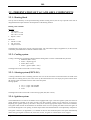
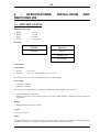
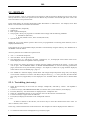
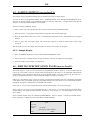
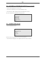
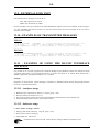
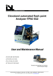
FP56 5G: TAG AUTOMATED
FLASH POINT ANALYZER
FP170 5G: ABEL AUTOMATED
FLASH POINT ANALYZER
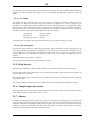
(3)
(4)
(1)
(2)
(1)
(2)
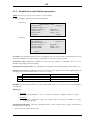
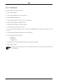
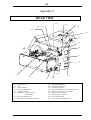
Control unit
Test unit
(3)
(4)
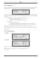
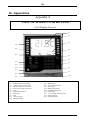
Sample temperature display
7 function keys on each side of screen
ACCORDING TO STANDARD METHODS ASTM D 56
(FP56 5G) IP 170, EN/ISO 13736, NF T 66-009 (FP170 5G)
USER MANUAL
V204A001-c
Page 1
ISL
REV
MODIFICATION DESCRIPTIVE
DATE
a
Original issue
98/08
b
Modification of section 2.2.1 “Heating rates
available”; 6.2.1 “Identification and definition
parameters”
Modification of section 8.3 “Test procedure”
02/08
c
Page 2
V204A001-c
02/10
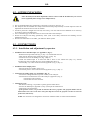
ISL
ADDENDUM
When the apparatus is placed on laboratory table,
Turn the adjustable feet in order to stabilize the apparatus.
Replace the thermal fuse on his support, under the serigraphy of the flame.
V204A001-c
Page 3
ISL
Page intentionally blank.
V204A001-c
Page 4
ISL
Instrumentation Scientifique de Laboratoire
Zone d'activités de la Mesnillière
B.P. 40
14790 VERSON
FRANCE
Tel.: +(33) 2.31.26.43.00 - Telex: 171966 F
Fax: +(33) 2.31.26.62.93
Reproduction of this document without permission is forbidden.
V204A001-c
Page 5
ISL
ISL (C) copyright
The FP56 5G and FP170 5G Analyzers and this manual are protected by copyright.
Reproduction of the unit will result in prosecution.
All rights to the manual are reserved. Reproduction in any form, including in the form of excerpts, shall require
written permission from the copyright holder.
ISL FP56 5G and FP170 5G Software© 2001, ISL
This software is owned by ISL and is registered under the registration number
IDDN.FR.001.520007.00.R.P.1997.000.30000 at the « Agence pour la Protection des Programmes », 119
Avenue de Flandre - 75019 Paris. It is protected in France by the « Code de Propriété Intellectuelle » laws and
internationally by international treaty provisions, and all other applicable national laws. It must not be copied,
reproduced, adapted, translated, rented or disassembled. This also applies to the accompanying manuals.
INFORMATION
Information in this document is subject to change without notice and does not represent a commitment on the part
of ISL. ISL provides this document "as is", without warranty of any kind, either expressed or implied, including,
but not limited to, the particular purpose. ISL may make improvements and/or changes in this manual or in the
product(s) and/or the program (s) described in this manual at any time. This product could include technical
inaccuracies or typographical errors. Changes are periodically made to the information herein; these changes may
be incorporated in new editions of the publication. Reproduction of any part of this manual without express
written permission is forbidden.
Translation in foreign local language (other than French or English)
Translation in other language than French and English have no contractual value and have been performed under
responsibility of the local distributor.
In any case the reference of the present literature will be the French and/or English release provided under ISL
copyright.
Page 6
V204A001-c
ISL
Reserved for Customer relations department :
No.: ................................
Date: .............................
CUSTOMER
REPORT
PURPOSE
I wish to
report an anomaly
make a suggestion/comment
receive further information
In the area of
Hardware
Software
Manual
ANALYZER ENVIRONMENT (please be as accurate as possible)
• HARDWARE
Type of Analyzer: ......................................
Serial No.: ...................................................
Options:
Parallel printer
Graphics printer
RS232C interface
Current loop interface
Other: ......................................................
• SOFTWARE
Plotter
Version: ........................................................
ATTACHED SHEETS
Listing
Diskette
Drawing
Text
Other
PROBLEM DESCRIPTION / COMMENTS
SUBMITTED BY
Name :
Company :
Address :
Phone :
To be returned to:
Telex :
Fax :
Date :
ISL
ZONE D'ACTIVITE DE LA MESNILLIERE BP40
14790 VERSON
FRANCE
or to your local Sales
office.
V204A001-c
Page 7
ISL
Page intentionally blank.
V204A001-c
Page 8
ISL
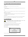
WARNING
The ISL Analyzer you have just acquired has been designed,
manufactured and inspected for quality. It is equipped with the
maximum number of safety features.
However, the use of this Analyzer involved the handling of solvents
and other potentially materials (flammability, toxicity, etc.).
You must therefore always be prudent and apply all appropriate
means for avoiding accidents.
The manufacturer accepts no liability arising from the use of this
Analyzer.
V204A001-c
Page 9
ISL
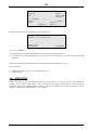
SYMBOLS USED IN THIS MANUAL
NOTE
Statements which indicate important information
and advice for the use of the unit.
CAUTION, WARNING
Statements indicating conditions or practices which
may be hazardous for the operator or equipment.
The values indicated in displays illustrated in this manual are given as examples and must not be
used by the operator for tests. ISL accepts no responsibility for accidents arising from the use of
values indicated in illustrations. This warning is particularly applicable (but not exclusively) to the
creation of a program.
Indications specific to only one of the two methods will be noted in bold italics with
indication of concerned equipment.
Example: Stirrer arm (FP170 5G)
Page 10
V204A001-c
ISL
CONTENTS
1 - GENERALITIES ........................................................................................................................................... 13
2 -PRESENTATION OF THE ISL FP56 5G/FP170 5G .................................................................................. 14
2.1 - THE ANALYZER ..................................................................................................................................... 15
2.2 - PRESENTATION OF TAG AND ABEL COMPONENTS ...................................................................... 16
2.3 - AVAILABLE ACCESSORIES ................................................................................................................. 18
2.4 - SOFTWARE CONFIGURATION ............................................................................................................ 18
3 - SAFETY FEATURES.................................................................................................................................... 19
3.1 - FAULTS AND OTHER ALARMS........................................................................................................... 19
3.2 - ACCESS CODES ...................................................................................................................................... 20
3.3 - OTHER SAFETY PRECAUTIONS.......................................................................................................... 20
4 - SPECIFICATIONS, INSTALLATION AND SWITCHING ON .............................................................. 21
4.1 - SPECIFICATIONS ................................................................................................................................... 21
4.2 - AFTER UNPACKING .............................................................................................................................. 23
4.3 - CONNECTIONS ....................................................................................................................................... 23
4.4 - SAFETY PRECAUTIONS FOR LCD DEVICES ..................................................................................... 25
4.5 - SWITCHING ON ...................................................................................................................................... 25
4.6. - PRINTER ................................................................................................................................................. 26
5 - KEYPAD AND LCD SCREEN..................................................................................................................... 27
5.1 - KEYPAD................................................................................................................................................... 27
5.2 - DISPLAY .................................................................................................................................................. 28
5.3 - ACCESS CONTROL - PASSWORDS ...................................................................................................... 29
5.4 - FAMILIARISATION ................................................................................................................................ 30
5.5 - MAIN MENU TEST.................................................................................................................................. 31
5.6 - SIGNIFICANCE OF THE VARIOUS DISPLAYED PHASES ................................................................ 31
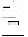
6 - PROGRAMMING: TESTS, PAGES, SAMPLES, OPERATORS, ETC. ................................................. 32
6.1 - TEST PRINCIPLE .................................................................................................................................... 32
6.2 - TEST PROGRAM PARAMETERS .......................................................................................................... 32
6.3 - PROGRAM CREATION (ACCESS LEVEL 1).............................................................................................. 35
6.4 - MODIFICATION OF AN EXISTING TEST (ACCESS LEVEL 1) ............................................................... 36
6.5 - SAMPLE EDITING (ACCESS LEVEL 1) ..................................................................................................... 37
6.6 - EDITING SPECIFICATION PAGES (ACCESS LEVEL 1) .......................................................................... 37
6.7 - OPERATOR NAME EDIT (ACCESS LEVEL 1)........................................................................................... 38
6.8 - CUSTOMISE RUN MODE SCREEN (ACCESS LEVEL 1).......................................................................... 39
7 - MEASUREMENT CHECKS AND SETTINGS.......................................................................................... 40
7.1 - TEMPERATURE MEASUREMENT ....................................................................................................... 40
7.2 - MEASUREMENT OF ATMOSPHERIC PRESSURE.............................................................................. 40
7.3 - GLOW PLUG CURRENT SETTING ....................................................................................................... 41
7.4 - FLAME SETTING .................................................................................................................................... 41
8 - TEST STARTING.......................................................................................................................................... 42
8.1 - DEFINITION AND SUMMARY OF THE METHOD.............................................................................. 42
8.2 - PREPARATION AND PROCEDURE ...................................................................................................... 43
8.3 - TEST PROCEDURE ................................................................................................................................. 44
8.4 - TEST RUNNING ...................................................................................................................................... 45
8.5 - AUTOMATIC TEST STOP ...................................................................................................................... 45
8.6 - TEST MODES........................................................................................................................................... 47
9 - RESULTS AND PRINTING ......................................................................................................................... 49
V204A001-c
Page 11
ISL
9.1 - RESULTS PAGES..................................................................................................................................... 49
9.2 - RESULTS .................................................................................................................................................. 50
9.3 - LAST RUN RESULTS .............................................................................................................................. 52
9.4 - PRINTOUT ............................................................................................................................................... 53
9.5 - PRINTER CONFIGURATION (ACCESS LEVEL 1) .................................................................................... 55
9.6 - PRINTER INTERFACE TEST.................................................................................................................. 55
10 - LAB MANAGER PARAMETER SETTINGS .......................................................................................... 56
10.1 - DEFAULT VALUES (ACCESS LEVEL 1).................................................................................................. 56
10.2 - LABORATORY CONFIGURATION (ACCESS LEVEL 1)........................................................................ 57
10.3 - REAL TIME CLOCK (ACCESS LEVEL 1) ................................................................................................. 57
10.4 - CUSTOMISE RUN MODE SCREEN (ACCESS LEVEL 1) ........................................................................ 57
11 - ALARMS ...................................................................................................................................................... 58
11.1 - ALARM TYPES ...................................................................................................................................... 58
11.2 - ALARM DISPLAY, ALARM STOP ....................................................................................................... 59
11.3 - ALARM HANDLING ............................................................................................................................. 59
11.4 - FAULT ALARMS ................................................................................................................................... 59
11.5 - ERROR OR REPORT ALARMS............................................................................................................. 63
11.6 - WARNING ALARMS............................................................................................................................. 64
12 - REGULAR MAINTENANCE..................................................................................................................... 66
12.1 - CLEANING THE CUP, COVER AND ACCESSORIES ........................................................................ 67
12.2 - REPLACEMENT OF THE TEMPERATURE PROBE........................................................................... 67
12.3 - ADJUSTING THE TEST FLAME .......................................................................................................... 67
12.4 - GLOW PLUG CURRENT SETTING ..................................................................................................... 67
13 - RS 232C STANDARD INTERFACE.......................................................................................................... 68
13.1 - SPECIFICATIONS.................................................................................................................................. 68
13.2 - EXTERNAL INTERFACE SETUP (ACCESS LEVEL 1)............................................................................ 69
13.3 - HARDWARE SETUP ............................................................................................................................. 69
13.4 - SOFTWARE SETUP............................................................................................................................... 70
13.5 - DATA FLOW CONTROL....................................................................................................................... 71
13.6 - COMPUTER ON-LINE........................................................................................................................... 73
13.7 - TRANSMITTED DATA ......................................................................................................................... 73
13.8 - RESULT MESSAGE FORMAT(CODE : ASCII - 90 CHARACTERS) ........................................................ 76
13.9 - EXTERNAL LINK TEST........................................................................................................................ 77
13.10 - EXAMPLES OF TRANSMITTED MESSAGES .................................................................................. 77
13.11 - EXAMPLE OF USING THE RS-232C INTERFACE WITH A PC....................................................... 77
14 - APPENDICES .............................................................................................................................................. 80
15 - INDEX ........................................................................................................................................................... 86
Page 12
V204A001-c
ISL
1 - GENERALITIES
With the FP56 5G/FP170 5G, ISL has once again developed an ergonomic and convivial petroleum product
Analyzer. Our committed customers will recognize ISL’s experience and reliability as well as the look and design
of the new generation of ISL instruments. The Analyzer you owned is the result of customer feedback and 20
years’ experience in the design and manufacture of petrochemical analysis equipment.
The FP56 5G Analyzers comply with ASTM D 56 standard methods and the FP170 5G comply with IP 170,
EN/ISO 13736, NF T 66-009 standard methods.
These standards do not define all associated safety procedures. It is therefore the
responsibility of the user to determine those procedures which are applicable.
A test sample is slowly heated at a constant rate in an enclosed chamber.
At the first flame application temperature, a small flame is applied by the opening of a shutter in the cover
(closed at all other times). The flame is lowered to just above the surface of the test sample where the vapors are
given off. The flame is then applied at regular temperature intervals to the lowest temperature at which the
application of the test flame produces the ignition of the vapors above the test sample.
DEFINITIONS*
Flash point, of petroleum product: The lowest temperature at which the application of a test flame results in the
ignition of a part of the vapor, under specific test conditions.
EFP: Expected Flash Point
The test sample is deemed to have flashed when an obvious flame appears and instantly
propagates across the sample’s surface.
V204A001-c
Page 13
ISL
2 -PRESENTATION OF THE ISL FP56 5G/FP170 5G
The ISL FP56 5G and FP170 5G can be used in two modes: Run menu or Main menu.
Run menu has been developed for the rapid start of a test. The operator can start a test simply by entering the
Expected Flash Temperature. He/she may also start a test simply by selecting a pre-programmed sample.
If necessary, a pre-programmed test and a pre-programmed operator can be entered. The laboratory manager may
associate a pre-programmed sample with a results specification page (see chapter 6, "PROGRAMMING:
TEST..."). The lab manager can thus configure the Analyzer for a default test which will be proposed to the
operator when selecting Run menu. Run menu can be used in several different ways (see chapter 8 "TEST
STARTING").
The main menu allows the operator to use all the Analyzer's functions. In particular, this mode allows the
Analyzer to be used for programs specific to the laboratory, provided that the related passwords are known.
The Analyzer is factory-set for the rapid selection of test programs compliant with all of the standards listed in
chapter 1.
Function selection is performed directly from the screen using 2 groups of keys situated to the left and right of
the screen. A "TEST RUNNING" display can be selected. It allows the display of the sample temperature (large
digits) which is readable from a distance of 5 m. The EFP, Analyzer status and glow plug current (when used) are
also displayed.
The other tactile-type keys, essentially used for data entry, are situated just below the screen.
The screen and keypad are resistant to most chemicals encountered in the petrochemical industry.
The sample temperature is measured in the cup by a Pt100 platinum probe.
The customer may choose between testing with a gas flame or an electrical igniter. Both types of ignition systems
can be installed (second as an accessory). Only one type of igniter may be assembled and connected at any given
time. Disassembly and assembly for the replacement of one igniter by the other is easily done.
The flash point detector is a thermocouple mounted on the test arm. When the test arm is manually positioned,
the thermocouple is automatically placed on the test cup cover.
An intermittent audible alarm is triggered when the test is terminated. A continuous audible alarm is triggered if a
fault prevents a test from being started or from continuing a running test. The origin of these alarms can be
displayed (see chapter 11 "ALARMS" for further details).
When a test is started, any detected minor anomalies which do not necessitate test termination are signaled as
"warnings" by an audible alarm and a "Warning No. XXX". The list of all possible warning numbers is given in
chapter 11 "ALARMS".
All faults are signaled by an audible alarm, the origin of which may be displayed. Certain faults switch the
Analyzer to standby (see the next chapter). All parts of the Analyzer having voltages greater than 24 V are not
accessible to the operator. The cup and cover are equipped with handles (except FP56 5G cup).
Page 14
V204A001-c
ISL
The Analyzer is equipped with a fire detection system which triggers an audible alarm. In this way, if a fire is
detected, the Analyzer switches power-consuming circuits to standby and disables the gas supply solenoid valve
command of the igniter. The customer may make use of the supplied safety relay to connect an additional fire
alarm and/or extinguisher as an accessory to the system.
The standard versions of the ISL FP56 5G and FP170 5G Analyzers are equipped with a parallel printer interface
and a simple RS 232C serial interface. See chapter 13 "EXTERNAL LINKS" for configuration of the RS 232C
serial interface and external links available as accessories.
The term "power-consuming device" is used in this manual to refer to electromechanical
and electrical components having a dedicated power supply. Purely electronic components
are not included in this category (for example, integrated circuits, Leds, etc.).
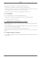
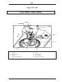
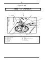
2.1 - THE ANALYZER
The ISL FP56 5G and FP170 5G Analyzers are compact and self-contained units. They can essentially be divided
into 2 units: the control unit and the test unit.
• The control unit, to the left, comprises:
•
•
•
•
•
Electronic boards,
Screen,
Keypad,
External interfaces (remote keypad, printer, RS 232C/current loop, ALAN, etc.),
Mains supply connector and ON/OFF switch.
• The test unit, on the right, comprises components specific to the flash point methods TAG and ABEL:
• Heating block, with well for holding the cup, and the cooling system,
• Standby support for the cover assembly (it can also take the cup),
• The following components are situated on the connection panel:
• connectors for the temperature probe, flash detector and ignition system
• gas connection tube (16-Appendice C)
• fire detection thermofuse
• In standby, the stirrer transmission arm is disengaged (FP170 5G). The test arm (igniter
application/shutter opening) is placed next to the central unit.
• The gas supply solenoid valve is situated at the rear of the test unit connection panel.
The igniter and its tilting mechanism are mounted on a test arm which serves the double purpose of opening the
shutter (of the cover) and igniter application. A caliber (4 mm) allows flame adjustment.
• The test cup and the cover assembly are positioned in the test unit well during a test. Test cover accessories
include the following:
• Stirrer (FP170 5G)
• Shutter
• Flash point detector connected to the test arm
• Pt100 sample temperature probe connected to the connection panel
These accessories may be removed from the cover by the operator.
V204A001-c
Page 15
ISL
2.2 - PRESENTATION OF TAG AND ABEL COMPONENTS
2.2.1 - Heating block
The cup well is heated by an incorporated heating element. During the test, the test cup is placed in the well. In
integrated thermocouple measures the temperature of the heating element.
Heating rates available:
FP56 5G:
• ASTM D56:
TP < 60°C: 1°C/mn
TP > 60°C: 3°C/mn
• Rapid: 3°C/mn
FP170 5G:
• ISO-IP: 1°C/mn
• NF: 0,5°C/mn
•
Rapid: 3°C/mn
The diagnostics mode can be used to control the heater. The red indicator light (6-Appendice C) on the test unit
connection panel illuminates to indicate when the heater is on.
2.2.2 - Cooling system
Cooling is obtained by circulating a fluid around the heating block. Various coolant fluids may be used:
• Methanol (EFP < 60°C)
• Water + ethylene glycol
• Water (EFP > 20°C)
• Water + glycerol (EFP > 50°C)
The diagnostics mode can be used to control cooling.
2.2.3 - Stirring system (FP170 5G)
A stirring transmission arm is manually placed on the cover at the start of the test and returned to its holder at the
end of the test. During the test, the rod is driven by the transmission arm. The step-by-step motor which drives
the stirring system is situated on the test unit connection panel.
Stirring speeds:
• 30 (+/- 5) rpm - ISO standard
• 75 (+/- 5) rpm - NF standard
• None
The diagnostics mode can be used to select stirring speed (ISO, NF or none).
2.2.4 - Ignition system
The standard FP56 5G or FP170 5G models can be equipped with a gas or electrical igniter system, the choice of
which should be specified at the time of order. The other ignition system can be ordered as an accessory.
Replacing one ignition system by the other is easily done. (See the appropriate chapter of the Service Manual.)
The igniter holder and the tilt mechanism are mounted on the test arm. Opening the shutter allows the igniter to
be lowered through the cover opening. A flame caliper allows test flame dimension to be adjusted by comparison.
The igniter connector (13-Appendice C) is situated on the test unit connection panel. The system automatically
detects the type of igniter connected. If, at the start of a test, no igniter is connected, the test is stopped.
Page 16
V204A001-c
ISL
The application position of the igniter can be adjusted by the operator. (See the "IGNITOR INSTALLATION"
chapter in the Service Manual.) The operator can use the "FLAME DIAGNOSTICS" function to apply the
igniter.
2.2.4.1 - Test flame
The Analyzer gas inlet is situated at the rear of the control unit. Gas supply is controlled by a solenoid valve and
the operator can adjust the test flame using a flow regulator (11-Appendice C). The gas supply tube (16Appendice C) is situated on the connection panel on the test unit. The test flame device is equipped with a flame
detector. The test flame is automatically lit at the start of the test. The flame detection system allows the flame to
be automatically re-lit in the event of extinction. During the test, if the flame is absent for more than 2 minutes or
if the flame is absent at the moment of flame application, the test is stopped.
Gas employed:
propane or butane
Inlet pressure:
100 mbar max.
Inlet operating pressure: 28 mbar
An optional pressure regulator allows gas pressure reduction for gas supply pressures up to 10 bars.
2.2.4.2 - Electrical igniter
The electrical igniter comprises an electrical glow plug and a support mechanism. The glow plug current can be
set using the adjustment potentiometer (17-Appendice C). The current can be read from the "TEST RUN" screen
- press <DISPLAY>. The glow plug is energized for 2 minutes at the start of the test then is stopped. It will be
energized again about 30 s before the tests. If the glow plug current is out of range (see chapter 7), the test is
stopped.
Recommended glow plug current: 7.5 A approx.
The glow plug can be manually controlled in diagnostics mode.
2.2.5 -Flash detector
The flash point is detected by a thermocouple. The detector is connected to the test unit connection panel.
Once the flash point has been detected, the test is stopped. The red indicator light on the connection panel is lit
when the flash point is detected.
The detection thermocouple is fixed to the test arm which allows the cover to be cleaned without risk of damage
to the thermocouple.
The test arm is manually advanced on the cover and the thermocouple is automatically brought into position.
2.2.6 - Sample temperature probe
The Pt100 temperature probe is placed in a holder/guide on the cover and is connected to the test unit connection
panel. Measuring range: -100 to +400°C/-148 to +752°F.
2.2.7 - Shutter
In standby, the igniter/shutter arm is placed next to the cover and the test unit connection panel. As in the case of
the stirrer arm, it is moved into position at the start of the test. The shutter is automatically opened at the igniter
application temperatures. Opening the shutter allows the igniter (gas or electrical) to be lowered into the cover
opening. The shutter is automatically shut after igniter presentation. Presentation and retraction of the shutter
opening arm can be manually controlled in diagnostics mode.
V204A001-c
Page 17
ISL
2.2.8 - Diagnostics
All diagnostics are presented in the "DIAGNOSTICS" chapter of the Service Manual.
2.3 - AVAILABLE ACCESSORIES
•
•
•
•
•
Gas igniter kit for installation on Analyzer initially equipped with electrical igniter
Electrical igniter kit for installation on Analyzer initially equipped with gas flame igniter
Vase and cover
Anti-draught shield
Printer
2.4 - SOFTWARE CONFIGURATION
The Analyzer's non-volatile memory contains pre-programmed test programs (in °C and °F) for all standard
methods listed in chapter 1.
The standard version of the FP56 5G/FP170 5G Analyzers is supplied with a diskette containing:
• Factory-set configuration (service parameters).
• PC software for:
• Transfer of service parameters from a host PC to the Analyzer.
• Transfer of service parameters from the Analyzer non-volatile backup memory to the PC.
• An external connection cable for data transmission.
Page 18
V204A001-c
ISL
3 - SAFETY FEATURES
All Analyzer parts with voltages exceeding 24 V are not accessible to the operator. The handles on the
test cup and cover allow both to be lifted without danger of burns. Any faults trigger an audible alarm. The origin
of fault, error or report alarms may be displayed. Certain faults switch the Analyzer to standby. If the detection of
one of these faults (refer to the list in the ALARMS section) does not result in the power circuits being switched
off, the operator must immediately switch off the Analyzer and disconnect it from the mains supply.
The system is equipped with a fire detector. On detection of fire, the system switches the Analyzer to
standby. A continuous audible alarm is triggered and remains activated until the Analyzer is switched off. The
user may connect an extinguishing accessory to the system’s safety relay. It is also possible to connect an external
alarm device. Refer to chapter 11, "STRIPPING DOWN..." of the Service Manual.
3.1 - FAULTS AND OTHER ALARMS
3.1.1 - Fire detection
A continuous alarm is triggered and the type of alarm can be checked by pressing (ALARM STOP). Any external
alarm/fire extinguisher connected by the user will be triggered by the fire detection fault.
• Control of the gas supply Solenoid Valve, the igniter and the bath cooling fan is disabled. The alarm
continues until the Analyzer is switched off.
3.1.2 - Consequences of switching to standby
All "power circuits" are switched to standby.
3.1.3 - Faults preventing the start of a test and stopping running tests
Refer to table in the "ALARMS" chapter.
These faults trigger a continuous audible alarm. Press (ALARM STOP) to display the type of alarm.
3.1.4 - Error or report alarms
The error alarms signal faults in the test run or the results. The only report alarm is the "End of test" alarm.
An intermittent audible alarm is triggered.
3.1.5 - Warning alarms for incompatibility corrections
This means that the system has corrected an anomaly in the test program. The conformity of the test run is
however guaranteed. An audible alarm is triggered and the corresponding warning number can be displayed by
pressing (ALARM STOP). The explanation for all warning alarms can be found in chapter 11, "ALARMS", of
this manual.
V204A001-c
Page 19
ISL
3.2 - ACCESS CODES
There are 3 access levels (levels 1 and 2 are password-protected):
• Level 0: User level.
Standard information and functions are accessible without password entry.
• Level 1: Laboratory manager level.
Level 0 + information and functions relating to the calibration report, quality and operator configuration are
accessible at this level.
• Level 2: Service level.
Level 1 + information and functions relating to servicing and technical configuration are accessible at this level.
The selection of access levels is covered in the "ANALYZER PROTECTION" chapter of the Service Manual.
Once an access level has been confirmed by entering the correct password, it remains available until a lower
access level is explicitly requested. When the system is switched on, it defaults to access level 0.
3.3 - OTHER SAFETY PRECAUTIONS
For further details concerning safety precautions of specific functions or modules, refer to the appropriate
sections of this manual of the Service Manual. Refer to chapter 4, "Specifications, installation and switching on"
for safety precautions relating to the use of the LCD screen.
Page 20
V204A001-c
ISL
4
SPECIFICATIONS,
SWITCHING ON
INSTALLATION
AND
4.1 - SPECIFICATIONS
Dimensions and weight
•
•
•
•
Height
Width
Depth
Weight
: 365 mm
: 345 mm
: 470 mm
: 19 kg approx.
Standards
FP56 5G
FP170 5G
ASTM D 56
IP 170
EN/ISO 13736
NF T 66-009
Environment
Temperature:
• Storage
• Operation
: -20 to +50°C
: 10 to 40°C - recommended range 15 to 35°C
For the LCD screen, refer also to the appropriate section of this chapter.
Power supply
• 215-240V / 50-60 Hz
• 100-115V / 50-60 Hz
The Analyzer is delivered with one of the above configurations at the request of the customer.
• Power consumption: 700 W maxi
• Lifetime of the battery for the backup memory/non-volatile RAM (nvRam): 3 months (200 h min.) with unit
switched off.
Heating
• Heating element: 200 W, low voltage
Cooling
• Fan: 24 V / 5.4 W
Igniter
The standard Analyzer is equipped with either a gas flame igniter or an electrical igniter, the other igniter being
available as an accessory. The required configuration should be specified when ordering.
V204A001-c
Page 21
ISL
Gas supply
• Connector on the gas Solenoid Valve : 10 mm external diameter
• Gas admission pressure: 100 mbar max.
(if pressure higher: see section 2.2.4.1)
• Silicone tube connecting the Solenoid Valve to the gas connection board outlet D5.5 - D3 mm
• Silicone tube to the igniter nozzle D3.5 - D1.5 mm
External link
• Centronics parallel printer interface
• RS 232C serial interface - with CTS, ENQ, ACK, XON, XOFF configurable protocol- on 9-pin output
connector (male).
Fire detection
• When fire is detected, an audible alarm is triggered and the Analyzer is switched to standby.
• The Analyzer is equipped with a safety relay to which an external fire extinguisher system and/or alarm may
be connected.
• Thermofuse: 75°C 250V AC 10A
Temperature measurement
• Measuring probe
• Measuring range
• Correction available
: Pt 100 probe
: -100 to +400°C
: in steps of 20°C / 36°F
LCD graphics display
•
•
•
•
•
Backlight
: cold fluorescent cathode
Resolution
: 320 * 240, 15 lines of 40 characters
Viewing area
: 120 * 90 mm approx.
Pixel size
: 0.33 * 0.33
Contrast and backlight : adjustable
Keyboard
Tactile type keys
The screen and the keypad are resistant to most chemicals employed in the petrochemical industry.
Stand-alone use
Can be used as stand-alone device and is supplied with standard external interface for transfer of results to a
host computer.
Page 22
V204A001-c
ISL
4.2 - AFTER UNPACKING
Once the Analyzer has been unpacked, it is best to leave it idle in the laboratory for several
hours (especially after storage at low temperatures).
• The recommended laboratory temperature is between 15 and 30°C (60 to 86 °F).
• The Analyzer must be installed on a steady horizontal benchtop and preferably in a fume cupboard. Turn the
adjustable feet under the unit in order to stabilize.
• It must be placed in a draught-free area and, if necessary, in an area which can be darkened if it is necessary
to be able to observe the flash point.
• Leave a minimum gap of 100 mm at the rear and on the sides of the Analyzer.
• Protect the Analyzer from being splashed by water (refer to the safety instructions for handling of LCD
modules further on).
• Re-insert the thermofuse in its holder, just under the flame symbol.
4.3 - CONNECTIONS
4.3.1 - Installation and adjustment by operator
• Installation of test thermocouple: (see Appendix 1, Fig. 2):
- Slide thermocouple inside tube (Fig. 2, Rep. 11) located under the arm.
- Then push the thermocouple inside the hole (Fig. 2, Rep. 12).
- Loosen the screw of the stuffing box (Fig. 2, Rep. 9)
- Install the thermocouple in its hole and slide it down to the Teflon base (Rep. 14), without
overshooting, then re-tighten the screw on the stuffing box (Rep. 9).
- Connect (Rep. 13) to the connection board.(Appendix 2, Fig. 1, Rep. 5).
• Installation of the sample probe:
- Insert the probe in its holder on the cover.
- Connect the probe to the connection board (Appendix 2, Fig. 1, Rep. 4)
• Connection of cooling supply (see Appendix 2, Fig. 1) :
- Connect the cooling unit tubes (cryostat or other) to the Analyzer.
- Connections are located at the rear of the Analyzer (Appendix 2, Fig 1):
* Fluid inlet on IN connector
* Fluid outlet on OUT connector
• Cleaning of cover:
- For efficient cleaning, it is possible to quickly put the shutter down :
- Unscrew the knurled pin (Appendix 7, Rep. 6) then put the shutter down.
- Clean using a solvent then dry.
- If the operator wishes, it is possible to dismount the stirrer propeller. The propeller blades must be
held and the drive shoe at the other end of the shaft unscrewed: the propeller can then be removed
from below (FP170 5G).
NOTE: the connectors are designed for connection of flexible tubes of 10 mm internal diameter.
V204A001-c
Page 23
ISL
4.3.2 - Configuration of Gas Test Flame:
• Gas connection:
- Connect a gas tube to the inlet connector (Rep. 1) located at the rear of the unit (Appendix 2, Fig. 1). If
the mains gas pressure is greater than 50 Mb, use a pressure regulator.
• Installation of a flame igniter/detector (see Appendix 1 Fig. 1)
- Loosen the screw (Rep. 4).
- Insert the igniter in the holder then re-tighten the screw (Rep. 4).
- Connect the igniter/detector to the connection panel (Appendix 2, Fig. 1, Rep. 2).
- Ignite the flame (diagnostic mode).
- Adjust the igniter so that its filament is next to the flame without entering the flame (Appendix 1, Fig.
1, Rep. 1). To do this, use the two appropriate screws (Appendix 1, Fig. 1, Reps. 4 and 5).
- The distance between the filament and the flame should be about 1 mm.
• Setup of a test flame - adjustment (Appendix 3):
- Loosen the two screws (Appendix 3, Rep. 1).
- Toggle the switch (Appendix 3, Rep. 2) (diagnostic mode).
- Insert the test flame tube (Rep. 3) and adjust depth.
- Re-tighten the two screws (Rep. 1).
- Press again the shutter maneuvering button (diagnostic mode) to bring the switch into its rest position.
- Connect the silicon tube from the test flame to the connection panel (Appendix 2, Fig. 1, Rep. 3).
4.3.3 - Configuration of Electrical Test Flame:
• Installation of an electrical test glow plug (see Appendix 3) :
- Put down the gas test flame tube (Appendix 3, Fig. 1, Rep. 3) and the igniter/detector (Rep. 4), if
present on the Analyzer.
- Toggle the switch (Rep. 2, diagnostic mode).
NOTE: For an ABEL type Analyzer, the ring (Appendix 3 bis, Figs. 2 and 3, Rep. 12) must be completely
removed and turned around.
- Insert the electrical glow plug (Appendix 3, Figs. 2 and 3, Rep. 10) in the switch (Rep. 2), adjust the
depth then tighten the screw (Rep. 1).
- Press again the movement button of the shutter (diagnostic mode) in order that the switch is in rest
position.
- Connect the glow plug to the connection panel (Appendix 2, Fig. 3, Rep. 10).
Important: Attach the glow plug wires under the clip (Rep. 11) paying attention to leave enough slack to allow
correct movement of the glow plug without hindrance.
NOTE: glow plug current must be adjusted when the first glow plug test is performed (see section B page 16).
Page 24
V204A001-c
ISL
4.4 - SAFETY PRECAUTIONS FOR LCD DEVICES
Scratches
• Avoid rubbing the screen with hard objects which may result in scratching.
Moisture/water
• Water on the surface of a functioning LCD screen can cause damage. Wipe with a clean soft cloth or leave to
dry before switching on.
Dirt
• The screen can be stained by fingerprints, saliva, starch, oil and fat. If it is stained, wipe with a clean soft
cloth.
High temperatures and humidity
• LCD modules are sensitive to high temperatures. Follow the operating and storage recommendations given in
the "Technical specifications " section of this chapter.
Vacuum cleaners
If the laboratory is cleaned using a vacuum cleaner, keep it away from the LCD (risk of electrostatic discharge).
Refer also to the appropriated section of the "STRIPPING DOWN..." chapter of the Service Manual.
4.5 - SWITCHING ON
Before connecting the Analyzer to the mains supply, check that the mains voltage
corresponds to that indicated on the rating plate on the rear of the unit.
Serious damage may result from using an incorrect voltage supply.
Before connecting peripherals, both the Analyzer and the peripheral must be switched off.
• Press the main ON/OFF switch (1-Appendice C) at the rear of the control unit.
• The screen should light up. If not, first check the contrast and backlight settings.
Display and self-test
The screen displays (for example):
ISL
FP56 5G
Groupe ISL
B.P. 40
14790 VERSON FRANCE
Tel: +(33) 2.31.26.43.00
Fax : +(33) 2.31.26.62.93
Press any key to continue. The screen displayed the Run Menu mode:
V204A001-c
Page 25
ISL
Sample ID:
Sample No.:
EFP: °C
Next N°
Previous EFP
<Run start>
Test : 1 ISO/ISO
°C
Operator:
<Exit>
Sample: 23.2
<Display>
<Down>
Bath : 23
Selecting <Exit> results in the display of the following screen:
ISL FP56 5G
Software V 1.4 V1.2 © ISL, 1996
Autotest : OK*
<Main menu>
S/N : XXX
<Run Menu>
(*) "OK" or "ERROR"
The self-test applies to the PROM, RAM and Non-volatile RAM (nvRam) memories.
• If a memory error is detected during power up, a test can only be started if, at least, the Analyzer is switched
off and on.
Information concerning the installed accessories is displayed in the middle of the screen:
External interface:
• The RS 232 interface accessory (with complete protocol),
• ALAN interface.
4.6. - PRINTER
Connect the printer to the 25-pin parallel printer port (4-Appendice C) at the rear of the control unit(before
switching on the Analyzer and printer). After switching on the Analyzer and the printer, check the printer
connection (refer to the "DIAGNOSTICS" chapter of the Service Manual). For printer configuration, refer to
chapter 9, "RESULTS AND PRINTOUT", in this manual.
Page 26
V204A001-c
ISL
5 - KEYPAD AND LCD SCREEN
5.1 - KEYPAD
The universal type (not specific to any particular language) has been kept simple. It has no alphabetic keys and
no double function keys. It includes:
•
•
•
•
•
•
•
•
•
Numeric keys,
Arrow keys (2 vertical and 2 horizontal),
Full stop and hyphen,
Backspace: cursor left, delete,
(ENT): for entry confirmation,
A reset key,
Stop keys for: a running test, alarm and printout,
Function keys on each side of the screen. They relate to the functions displayed at any given time.
Built-in indicator lights:
- "TEST": green, test running,
- "ALARM": red, fault, error and report alarms - continuous audible alarm.
The keypad is made watertight by a polyester film.
Text entries (sample ID, operator, etc.) are selected using the screen. When an entry requires text, the alphabet
and 6 other characters are displayed. Text is then edited as explained in "Editing text" in section B this chapter.
Function keys
(RESET) Abandons all data entry or quits creation/sample display, creation/page display and
creation/display of test program.
(PRINT STOP) Stops printout
(STOP ALARM) Displays the origin of the triggered alarm. The audible alarm can be muted (except in the
case of fire detection) using the screen.
(BACKSPACE) Delete preceding character
Full stop
Hyphen
STOP
ENT
(STOP) Abandons the running test - started using "TEST START". For further details, see the
relevant section in chapter 8.
(ENT) Confirmation of entry: a single letter, a block of text, a value, etc.
Direct selection of functions displayed on the screen.
(UP/ DOWN) - (LEFT/RIGHT) arrow keys: allows selection of letters of the
alphabet,
(UP/DOWN) - Also used for incrementing/decrementing numbers
(LEFT/RIGHT) - Also used for selecting the position of numbers
V204A001-c
Page 27
ISL
5.2 - DISPLAY
The LCD graphics screen is incorporated in the keypad so that the functions displayed on the screen can be
directly selected. To do this, the operator uses the function keys situated to the left and right of the screen. The
LCD screen has its own protective film.
In the initial display, the operator should select either "Run Menu" or "Main menu ". For example, select <Run
Menu>. Several entries are available in Run Menu :
•
•
•
•
Sample identifier (sample ID),
Sample No.,
EFP: expected flash point,
The program - factory-set programs are available which comply with the following standards:
• ASTM D 56 (FP56 5G)
• IP 170, EN/ISO 13736, NF T 66-009 (FP170 5G)
• Operator name,
Sample ID, type of test and the operator name can be pre-programmed. On selecting these functions, a list is
displayed (maximum 20).
If not entered via a pre-programmed sample, the EFP is entered directly using the EFP key. See "ENTRY OF A
NUMERIC VALUE" below.
Accessory functions are available for rapid test start:
• "No ++": increments sample No.,
• "Previous EFP": Use the previous EFP.
• The temperature, "T", and the No. of igniter applications, "A", are displayed at the bottom of the screen.
These displayed values are updated as the test proceeds.
• The <Down> key allows the operator to display the page numbers allocated for the results - "in spec" and
"out of spec". The "SAMPLES EDIT" of "RUNS ENVIRONMENT" is used for allocating specification
pages (restricted to use by the laboratory manager - see chapter 6). If there are no page numbers displayed,
results will be sent to the default page - page 21.
• The <DISPLAY> function displays "TEST RUN" with 4-digit sample temperature (large size). The display
can be read at a distance of 5 meters. The EFP, Analyzer status (e.g., "--> tests"), the date, the time and the
glow plug current (if applicable) are also displayed. The <FLAME TEST> function starts a manual flame
test.
5.2.1 - Text editing (text entry)
• Select the line directly on the screen (for example, "Sample ID", followed by <Other>. The alphabet is
displayed.
• Use the arrow keys (LEFT/RIGHT/UP/DOWN) to select the letter (or the character) on the display.
• Press the (ENT) key - the selected letter is displayed in the "Sample ID" box.
• Select the <Alpha/Edit> function so as to place the cursor for the selection of another letter.
• Use the arrow keys to again select the 2nd letter.
• Press (ENT) to display the 2nd letter in the "Sample ID" edit box.
• Etc.
To delete a character in the edit box, use the arrow keys to select the character then select <Del>. To
insert a character, select <Inser>.
In this way, confirm each character of the desired text. The complete text will be displayed in the "Edit box" :
• To confirm the entire block of displayed text, press (ENT) again.
Page 28
V204A001-c
ISL
The preceding screen reappears with the text displayed in the "Sample ID" line.
• To abandon editing, press (RESET).
Entry of text and numeric values
Display the alphabet by selecting, for example, " Sample ID". You may now enter letters and numbers to type a
name like "ISO/ISO C". When the cursor is positioned in the "Sample ID" edit box, numbers may be entered
directly from the keypad.
5.2.2 - Entry of a numeric value
• Using the appropriate function key, select the line directly on the screen (e.g. EFP). The cursor is positioned
for data entry.
• Use the horizontal arrow keys (LEFT/RIGHT) to select digit position and the vertical arrow keys
(UP/DOWN) to increment/decrement the value. The numeric keys on the keypad may also be used.
• Display the desired value by pressing (ENT) to confirm the value.
5.2.3 - Flip-flop entries
This is the simplest form of parameter setting, for example: "Y/N", "°C/°F" and stirring speed (FP170 5G)
« ISO »/ « NF »/ « none ». The operator need only press the key until the desired setting is displayed.
5.3 - ACCESS CONTROL - PASSWORDS
The menus and functions have been classified according to access levels. The first level, level 0, can be accessed
by all users. The other levels, Levels 1 and 2, are password protected. If the operator attempts to access a
function whose access level is higher than the currently validated access level, the message "ACCESS DENIED"
is displayed and the user is asked to provide the password.
• These access levels are explained in chapter 3 of the User Manual. Factory set passwords are given in chapter
3 of the Service Manual.
• Modification of the laboratory manager password is described in chapter 10, "LAB MANAGER
PARAMETER SETTING" of the Service Manual.
• Modification of the Service password is explained in chapter 5, "SERVICE PARAMETERS", of the Service
Manual.
To check current access level, select <Main menu> then select <Access> from the main menu. The "ACCESS
CONTROL" display appears.
• At power on, the default access level is "0".
V204A001-c
Page 29
ISL
5.4 - FAMILIARISATION
In this manual, the term "select" means "press" the key corresponding to the indicated
function.
• Enter the Flash Point test and the display shows:
Sample ID:
Sample No.:
EFP:
°C
Test:
Operator:
<Exit>
Sample:
Next No
Previous EFP
<RUN START (E)>
<Display>
<Down>
Bath:
Several entries are available via the keys to the left and right of the screen.
• Select "Sample ID" and choose one of the pre-programmed samples.
• Select "Operator" and choose one of the pre-programmed operator names.
• Select "Test" and choose one of the pre-programmed test programs.
• Select "Sample No.". Enter the sample number as explained in the "ENTRY OF TEXT AND NUMERIC
VALUES" section of the is chapter. You may also use the "No ++" function to increment the sample No.
used for the previous test.
• Select "EFP" and use the keypad to type in the Expected Flash Point. Press (ENT) to validate. You may also
use the "Previous EFP" to re-select the EFP from the previous run.
If the unit has been prepared correctly, and after having selected the required entries from those listed above, the
test may be started. To do this, select the "RUN START" function key. The type of igniter device connected is
indicated; "G" for gas and "E" for electrical. If no igniter is connected, "E" is displayed. For the full test start
procedure, see chapter 8 "TEST STARTING".
Several Run Menu procedures are available (see chapter 8, "TEST STARTING").
Manual flame test
• Select <Display> from the "Main menu" or from "Run Menu" to activate the display of "CURRENT TEST".
• Select <Flame test> to identify the igniter at any point during the test.
Page 30
V204A001-c
ISL
5.5 - MAIN MENU TEST
• Select <Main menu>, then choose "FULL MODE RUN" from the main menu.
5.5.1 - With the loaded test program
If the operator decides to use the program loaded in the memory, he/she must select "DOWN..." and start the test
using the same procedure as for "Run Menu". Refer to section D of this chapter.
5.5.2 - With modified loaded test program or another program
If the operator wishes to modify the program loaded in the memory or would like to change any other program in
the memory, he/she must select "PREPARE THE RUN".
The following must then be done:
• Modify the program in the memory (when "Full mode run" is selected),
• Load another program in the memory then modify it,
• Save the modified program,
• Select "DOWN..." and start the run using the same procedure as that used for "Run Menu". (Refer to section
D of this chapter.)
To print the program in the memory, select "PRINTING".
5.5.3 - Test details in Main menu
In Main menu, the operator can view all the details of the test program by selecting <Down> in the "Test start"
display.
5.5.4 - End of Main menu
To end Main menu, so as to start a Run Menu test, the operator must select "END OF FULL MODE RUN". If a
test program has been created in Main menu (but not saved), it will be lost on quitting Main menu (when the
operator confirms by selecting <OK>). The context of the program in memory will be lost when quitting Main
menu. To save the program created in Main menu, "SAVE THE CURRENT TEST" from "PREPARE THE
RUN" must be used before quitting Main menu.
5.6 - SIGNIFICANCE OF THE VARIOUS DISPLAYED
PHASES
Idle
Ignition
----> Tests
Tests
Presentation
Cooling
The unit is in standby mode (no test).
Ignition of glow plug - about 15 seconds
Gas ignition - as long as the flame is not lit (within the limits imposed by the "No test flame"
fault alarm).
Phase preceding the test start temperature.
The test start temperature has been reached.
Automatic presentation of the igniter
Heating block cooling after test stop.
V204A001-c
Page 31
ISL
6 - PROGRAMMING: TESTS, PAGES, SAMPLES,
OPERATORS, ETC.
6.1 - TEST PRINCIPLE
A test program consists of a name and a series of parameter guidelines. The laboratory manager can store up to
20 test programs, numbered from 1 to 20. The parameter values depend on the sample to be analyzed. These
parameters are defined in the various standard methods (e.g., ASTM D 56 (FP56 5G) or ISO 13736 (FP170 5G),
etc.). A non-standard program can also be created.
The Analyzer is factory-configured for rapid selection of test programs according to all the standards listed in
chapter 1.
The customer can of course replace unneeded test programs by test programs specific to the laboratory. Any
modifications applied to an existing standard can be immediately applied by the customer by making
modifications to the corresponding test program, without having to wait for a software upgrade.
Having created test programs corresponding to the various standard and non-standard methods, up to 20 preprogrammed sample types (defined by the laboratory manager) can be created. A test program can be associated
with each sample type created. Pre-programmed samples are saved with an identifier and under a number from 1
to 20. Thus, when a pre-programmed sample type is selected by the user, the associated test program is called.
Editing of pre-programmed sample types is explained in the "SAMPLE EDITING" section of this chapter.
6.2 - TEST PROGRAM PARAMETERS
Before starting program creation, let us first consider the various parameters and the information which makes up
a program.
• Select "DISPLAY A TEST" in the "RUNS ENVIRONMENT" menu.
TEST DISPLAY
Selected test: _
Show test list
<Display selected test>
<Exit>
Select "SHOW TEST LIST" and the list of existing tests is displayed (1 to 20). Select one of the tests, e.g., test 1.
The previous display returns and "1" is displayed on the "SELECTED TEST" line.
Page 32
V204A001-c
ISL
6.2.1 - Identification and definition parameters
NOTE: The values given in the screens below are only examples.
• Select <Display> and the screens below are displayed.
* FP170 5G :
DISPLAYING A TEST
Tmp unit: °C
Name: ISO 13736
Bath setpoint at EFP - 17 °C
Barometric correction: 1
Rounded: N
Heating rate: ISO
if EFP <= 19 °C
Heating rate: ISO
if EFP > 19 °C
Stirring: ISO
<Down>
* FP56 5G :
DISPLAYING A TEST
Name: ASTM D 56
Tmp unit: °C
Bath setpoint at EFP - 10 °C
Barometric correction: 1
Rounded: N
Heating rate: LOW
if EFP <= 60 °C
Heating rate: HIGH
if EFP > 60 °C
<Down>
Test name: This parameter allows the test to be identified. The user can thus check if the displayed test is that
which he/she intends to run before starting . A maximum of 12 characters may be entered.
Temperature units: Depending on whether you wish to work in Celsius or Fahrenheit, enter "C" or "F".
Parameter entry during creation is flip-flop.
Heating block set-point at EFP - °C: Depending on the standard used, the heating block must be at EFP - x°C.
Barometric correction: An automatic barometric correction can be requested, which will be applied during the
calculation of the results. Flip-flop entry of "1" or "2" or « none ».
1
2
none
FP56 5G
In accordance with ASTM D56-01
No correction
FP170 5G
In accordance with ISO 13736 / IP 170-99
In accordance with NF T66-009
No correction
Rounded: there are 2 possible entries: "Y" (yes: rounded nearest to 0.5°C or 1°F) or "N" (no: no rounded). Entry
is by flip-flop.
Heating rate:
• FP56 5G:
There are 2 possibilities: " Low" (1 °C/min or 2 °F/min) or " High"(3 °C/min or 5 °F/min).
• FP170 5G:
There are 3 possibilities: « NF » (0.5 °C/min), « ISO » (1°C/min) or « RAPID » (3 °C/min).
Entry is by flip-flop.
Stirring speed (FP170 5G): There are 3 possibilities "None" - "ISO" (30 rpm), "NF" (75 rpm). Parameter entry
during creation is by flip-flop.
• Press <Down> to display the next page.
V204A001-c
Page 33
ISL
6.2.2 - Initial phase
This phase is optional. It allows presentation of the igniter before reaching the temperature defined in the
standard method - EFP - °C. This phase can be used to determine an approximate value for the sample EFP.
INITIAL PHASE
Test every 999.9 °C
Test every 999.9 °C
Start tests at - 99 °C
<Up>
if EFP =< 60 °C
if EFP > 60 °C
<Down>
For this phase, it is possible to define only one flame presentation. In this case, a test is performed at the start of
the rapid phase, the following test being the first of the standard phase. To achieve this, enter the following
parameters:
• Test start:
• EFP - 99: always a first application of the flame at the start.
• EFP 999.9: No flame presentation.
• Entering 10°C results in the flame being presented 10 °C.
• Test frequency:
• EFP 999.9: no presentation.
• If a temperature is programmed at the « start of the test », there will be one test only.
• Entering a value between 2°C and 10 °C (for example: 3 °C), a test will occur every 3°C.
Test every: his parameter defines test flame frequency. It can be programmed between 2 and 10°C.
Test start: If the rapid phase is used, this parameter defines the temperature at which the flame is first applied.
• Press <Down>.
6.2.3 - Standard phase
•
FP56 5G
STANDARD PHASE
<Up>
Test every 0.5 °C
if EFP =< 60 °C
Test every 1.0 °C
if EFP >60 °C
Start tests at EFP - 5 °C if EFP =< 60 °C
Start tests at EFP - 5 °C if EFP > 60 °C
<Down>
• FP170 5G
STANDARD PHASE
Test every 0.5 °C
Test every 0.5 °C
Start tests at EFP - 10 °C
Start tests at EFP - 10 °C
<Up>
if EFP =< 19 °C
if EFP > 19 °C
if EFP =< 19 °C
if EFP > 19 °C
<Down>
Test every: this parameter defines test flame frequency. It can be programmed at 0.5°C.
Test start: Tests start at - 5°C (FP56 5G) or - 10 °C (FP170 5G) before the EFP.
• Press <Down>.
Page 34
V204A001-c
ISL
6.2.4 - Final phase
FINAL PHASE
Go - No Go : N
Pre-safety at EFP: + 10 °C
Safety at EFP: + 15 °C
<Up>
(test at EFPonly)
<Exit>
GO-NO GO: To program a single test flame at the EFP, this parameter must be "Y" for yes. Enter "N", for no, to
allow several flame presentations, depending on the standards. When this parameter is "Y", the test start
temperature (initial phase and standard phase) is not taken into account. Entry is by flip-flop.
Pre-safety alarm at EFP+: An intermittent audible alarm can be programmed for a given temperature above the
EFP.
Safety alarm at EFP+: An intermittent audible alarm can be programmed to switch the Analyzer to standby at a
given temperature above the EFP. See chapter 3, "SYSTEM SAFETY FEATURES..." for the consequences of
the Analyzer switching to standby mode. The red alarm indicator is illuminated.
6.3 - PROGRAM CREATION (access level 1)
• Select "RUNS ENVIRONMENT" in Main menu.
• Select "CUSTOMIZE A TEST".
CUSTOMIZE A TEST
Selected test: 1
Show test list
New one
<Edit selected test>
<Exit>
• Select "NEW ONE" and the first page of program entry is displayed. Enter the parameters for the various
phases as indicated in section 6.2 « Test program parameters ».
When all the parameters have been entered and "FINAL PHASE" is displayed:
FINAL PHASE
Go - No Go: N
Pre-safety at EFP +: °C
Safety at EFP +: °C
<Up>
(1 only at EFP)
<Cancel>
<Ok>
• Press <Ok> and the following is displayed :
V204A001-c
Page 35
ISL
EDIT SELECTED TEST
Save
Save as...
<Exit>
• Select "SAVE AS" and the list of existing tests is displayed (1 to 20).
Save as...
1:
2:
3:
4:
5:
<Exit>
6:
7:
8:
9:
10:
<Down>
• Select <Down> to display the next page (11 to 20).
• Select the number of the program displayed and the "TEST DISPLAY" screen appears. The test number
which you have just selected is displayed.
• To return to the first display of the section C without saving the program, select <Exit>.
The new program has therefore been saved under the displayed number. If, in the future, the user modifies the
program, "SAVE" can simply be selected to save the program under the same number.
6.4 - MODIFICATION OF AN EXISTING TEST (access level 1)
• Select "RUNS ENVIRONMENT" in Main menu.
• Select "CUSTOMIZE A TEST".
CUSTOMIZE A TEST
Selected test: 1
Show test list
New one
<Edit selected test >
<Exit>
• Select "SHOW TEST LIST".
• Select the program to be modified from the list and the previous screen is displayed. The "Prog No." must
display the selected number.
• Select <Edit selected test> and the program is displayed.
The modification and the saving of an existing program is carried out in the same way as for a new program, see
section 6.3 « Program creation ». It can be saved under the same program No. (modification) or under a new
program No.
Page 36
V204A001-c
ISL
6.5 - SAMPLE EDITING (access level 1)
The purpose of pre-programmed sample types is explained in section A of this chapter.
To create or edit a pre-programmed sample, select " SAMPLES EDIT" in the "RUNS ENVIRONMENT" menu.
The user can list the existing pre-programmed samples by selecting <Show list>. A sample number must then be
selected - an existing sample number or a free number.
From the resulting "SAMPLE" display:
• Select <Edit> to go into editing mode. The screen title then becomes "SAMPLES EDIT"
• Select "Prog No.". The program selected must correspond to the selected sample type.
• Enter the name and the EFP (20 to 350°C). The displayed temperature units is selected during test program
creation.
• Enter "in spec" and "out of spec" pages. The "out of spec" page can be either the same as the "in spec" page
or page 21.
The user must now save the sample. The principle is the same as for saving a test program.
6.5.1 - Sample display
• Select "SAMPLES DISPLAY" from the "RUNS ENVIRONMENT" menu.
• Select <Show list> to display the list of existing samples. (<Down> to display the second page)
• Select the number of the sample to be displayed.
6.6 - EDITING SPECIFICATION PAGES (access level 1)
The results pages 1 to 20 are reserved for the pre-programmed samples. (Page 21 is also available and can
receive up to 50 results.) The user can edit results specifications for the pages 1 to 20. Minimum and maximum
specifications can be associated with all the pre-programmed samples. The page numbers for the results of a
given pre-programmed sample are selected when this sample is edited (see section E).
Editing of a specification page consists of entering a maximum permissible result and a minimum permissible
result. When a test is performed using a pre-programmed sample, the result (observed, corrected and/or rounded depending on program configuration) is compared with its limits.
If the result is "in spec" when compared with the associated results page, it is stored in this page.
If the result of a test using a pre-programmed sample is "out of spec", it is stored in the page defined during
sample editing. If no page has been specified, the result is stored in page 21 - the default page for all "out of
spec" results.
Select "PAGES EDIT" from the "RUNS ENVIRONMENT" menu to display a "OUTPUT PAGES EDIT".
Select <Show list> to display the list of "OUTPUT PAGES NAMES".
OUTPUT PAGES EDIT
<Show list>
No.:
Title:
Spec. min:
Spec. max.:
Storage:
25 results
*0 storage (s) still available*
<Exit>
<Edit>
V204A001-c
Page 37
ISL
To display the list of existing pages, select <Show list> the select the page number.
• Select <Edit> to go to editing mode. The screen title changes to "RESULTS PAGE"
• Enter the title, "Spec. min.", the "Spec. max." and the maximum number of results spaces reserved for the
page. For further information on these spaces, refer to chapter 9, "RESULTS..."
• After displaying all entries, select <Ok> and save the page under a number (1 to 20).
6.6.1 - Page display
• Select "PAGES DISPLAY" from the "RUNS ENVIRONMENT" menu.
• Select <Show list> to display the list of existing samples. (<Down> to display the second page)
• Select the number of the page to be displayed.
6.7 - OPERATOR NAME EDIT (access level 1)
To facilitate test start, 20 operator names can be prepared. In this way, the user does not need to edit an operator
name when starting a test.
• Select "OPERATOR EDIT" from the "RUNS ENVIRONMENT" menu to display the first page of the
operators list. (<Down> to display the second page)
• Select the operator number and enter the operator name as explained in chapter 5.
After validating the entry by pressing (ENT), the name is saved in the list. Select <Exit> to return to the previous
display.
6.7.1 - Display of the list of operators
• Select "OPERATORS DISPLAY" from the "RUNS ENVIRONMENT" menu to display the first page of the
list of operators.
Page 38
V204A001-c
ISL
6.8 - CUSTOMISE RUN MODE SCREEN (access level 1)
It is possible from access level 1 to customize the Run Menu screen in terms of entry and display. Five of the
functions of this screen are left to the choice of the laboratory manager. Furthermore, if the laboratory manager
decides to display these functions, he/she can prevent their modification.
• Select "CUSTOMISE RUN MODE SCREEN" from the "RUNS ENVIRONMENT" menu.
• Select the concerned function to modify the screen configuration - "Y" to display and "N" to hide.
The concerned display items are:
•
•
•
•
Sample ID,
Sample No.,
Test ID,
Operator name,
V204A001-c
Page 39
ISL
7 - MEASUREMENT CHECKS AND SETTINGS
To ensure that the results are reliable, your Analyzer’s results can be quickly checked. These checks must be
performed at regular intervals, in compliance with your organization’s quality system.
7.1 - TEMPERATURE MEASUREMENT
For this measurement, the operator requires a PS 100 probe simulator. Do not forget that it is not possible to
carry out temperature checks while a test is running.
• Disconnect the temperature probe from its connector (14-Appendice C) and replace it with the probe
simulator.
• From the "RUN MENU" screen, select <Display>.
• Set the PS 100 switch to - 50°C.
• Wait for the temperature measurement to stabilize and check that it is - 50°C.
• Now set the PS 100 switch to 100°C and, after the temperature display has stabilized, check that it is 100°C.
If calibration is necessary, consult the "QUALITY" chapter of the Service Manual.
These checks must be performed at regular intervals, in compliance with your organization’s
quality system.
7.1.1 - Probe correction
The probe can be corrected by the use of a table -50-100°C, with a 20°C step. Refer to the "SERVICE
PARAMETERS" chapter of the Service Manual. This correction is applied only during test.
Correction of probe response time
The probe response time is corrected so as to be equivalent to that of the thermometer. This correction is applied
permanently.
7.2 - MEASUREMENT OF ATMOSPHERIC PRESSURE
The operator must have a reference barometer
• Select "SERVICE" in the main menu.
• Select "MEASURES DISPLAY" to display the current measurements from the Analyzer.
• Check that the "ATM PRS" reading is the same as the reference barometer reading.
If calibration is necessary, refer to the "QUALITY" chapter of the Service Manual.
Page 40
V204A001-c
ISL
7.3 - GLOW PLUG CURRENT SETTING
This setting, if necessary, should be performed at the start of the test.
Adjustment of the glow plug current can be performed at the start of a test or in the diagnostic mode. When the
test is started, "TEST RUNNING" is displayed. The glow plug current can be read at the bottom of the screen.
1. 15 seconds after the start of the run, the glow plug current is tested. If the current is outside of the limits (<3A
and > 9A), the test is abandoned.
2. The glow plug remains on for a further 2 minutes, during which the current is tested. This period allows the
operator to adjust the current to the recommended value of 7.5 A.
An adjustment screw (17-Appendice C) is situated on the connection panel of the test unit (next to the igniter
connector).
If the glow plug current is not within the limits (< 3A and > 9A) within 15 seconds of being
ignited, the test is abandoned. The glow plug current is also tested from the start of igniter
presentation through to the end of the test.
When the glow plug is ignited, it should not be possible to distinguish the different coils. At the
start of the glow plug life, the current value corresponding to this phenomenon is 7A. After
extended use, the ignition efficiency of the glow plug decreases. The glow plug current must be
constant for comparable flash point tests.
7.4 - FLAME SETTING
Use the gas flow regulator (11-Appendice C) to adjust the diameter of the flame by comparison with the diameter
of the flame caliber on the igniter holder.
Loosen the two screws situated on each side of the flame caliber to adjust its position.
V204A001-c
Page 41
ISL
8 - TEST STARTING
8.1 - DEFINITION AND SUMMARY OF THE METHOD
8.1.1 - Definition
The flash point is the lowest temperature, corrected to a barometric pressure of 101.3 kPa (760 mmHg), at which
the application of a test flame causes ignition of a part of the sample’s vapors under specified test conditions.
8.1.2 - Specifications of the IP 170, EN/ISO 13736, NF T 66-009 and ASTM
D 56 standards
STANDARD
IP 170
EN/ISO 13736
NF T 66-009
ASTM D 56
1st flame application
EFP - 9 °C
EFP - 10°C
EFP - 10°C (18 °F)
Test frequency
0.5 °C (1 °F)
1 °C (2 °F)
0.5 °C (1°F) if EFP >= 60
°C
1 °C (2 °F) if EFP < 60 °C
Heating rate - °C/min
(°F/min)
1 °C (2 °F)
0.5 °C (1 °F)
1 °C (2 °F)
if EFP >= 60 °C (110 °F)
3 °C (5 °F)
if EFP < 60 °C (110 °C)
Stirring speed - rpm
30 (± 5)
75 (± 5)
No stirring
Page 42
V204A001-c
ISL
8.2 - PREPARATION AND PROCEDURE
8.2.1 - Sampling
To avoid the loss of vapors from the test sample and to protect the test sample from contamination by humidity,
do not open the sample container. Do not handle the sample at temperatures above the EFP - 10°C (20°F). The
flash point test must be the first test subjected to the test sample.
Refer to the standard for other sampling recommendations.
8.2.2 - Preparation
The operator must be informed about the dangers relating to flash point testing. Some of these
dangers are indicated in the standards. Handle test samples and waste solvents in compliance with
applicable regulations.
The flame (gas ignition) is lit automatically at the start of the test. A device allows flame
extinction to be detected. In the event of extinction, the flame is automatically re-lit.
• The flash point tests should be performed in a draft-free room. If the unit is equipped with an anti-draught
screen (supplied as an accessory), install it before starting the test.
• Make sure that the Analyzer is placed on a stable and horizontal benchtop.
• Thoroughly clean and dry all parts of the cup and its accessories before starting the test.
• Carry out the checks described in the preceding chapter regularly. See also chapter 12, "REGULAR
MAINTENANCE".
For other preparation procedures, refer to the standard.
V204A001-c
Page 43
ISL
8.3 - TEST PROCEDURE
8.3.1. TAG standard method
1. Place the cup in the heating block. The two positioning (and clamping) mechanisms on the upper edge of the
heating block must engage in the two guides on the edge of the cup.
2. Fill the cup with the test sample, 50 mL of sample at least for each test.
3. Place the cover on the cup and turn clockwise to clamp onto the cup.
4. Connect the flash point detector and the temperature probe to the connection panel. Insert the probe in its
holder on the cover.
5. Install the draught protection screen (if the Analyzer is equipped with this option).
8.3.2. ABEL standard method
1. Place the cup in the heating block. The two positioning (and clamping) mechanisms on the upper edge of the
heating block must engage in the two guides on the edge of the cup.
2. Fill the cup with the test sample until the level reaches the point of the index gauge on the wall of the test cup.
3. Place the cover on the cup and turn clockwise to clamp onto the cup.
4. Connect the flash point detector and the temperature probe to the connection panel. Insert the probe in its
holder on the cover.
5. Engage the stirrer transmission arm on the test cover cup (as it is represented in Appendix B2)
6. Install the draught protection screen (if the Analyzer is equipped with this option).
8.3.3. Igniter check after starting test:
A. If the Analyzer is equipped with a gas flame igniter, check by comparison that the flame dimension is the
same as that of the flame caliber on the gas igniter support. If not, use the gas flow regulator (11-Appendice
C) to adjust it (flame diameter: 3.2 to 4.8 mm).
B. If the Analyzer is equipped with an electrical igniter, the "TEST RUN" screen appears allowing the glow plug
current to be read at the bottom of the screen. If necessary, the operator has 2 minutes to adjust the glow plug
current.
Several test start procedures are indicated in section 8.6 of this chapter. The operator can choose that which best
corresponds to his/her needs.
Between two tests, the cover and the probe can be cleaned together - after disconnecting the
probe. In this way, the probe can be positioned in its holder before placing the cover on the cup.
In the event of the gas flame being unexpectedly extinguished, the gas might enter the space above
the test sample in the cup. This contamination could affect the result.
The glow plug current should be 7.5 A. See the "GLOW PLUG ADJUSTMENT" section in the
previous chapter. If the glow plug current is not within the limits (< 3A and > 9A), a fault alarm is
triggered and the test is abandoned.
Page 44
V204A001-c
ISL
8.4 - TEST RUNNING
The "TEST RUNNING" screen is displayed when the test is started. The EFP can be modified in the "TEST
RUNNING" screen or the "TEST START" screen during the test. (See chapter 5 for a description of the meaning
of the "Analyzer :" indicators in the "TEST RUNNING" screen.
When the igniter is applied, the large size temperature display is locked. The display is unlocked only if the flash
point is not detected.
In this way, when the flash point is detected, the temperature at which the flash point was detected remains
displayed after the test has been automatically stopped.
Manual flame test
The operator can manually apply the igniter at any time during the test (or in standby mode) by selecting <Flame
test> in the "TEST RUNNING" screen.
Manually stopping a test
• Press the (STOP) key on the keypad.
• Confirm that you wish to stop the running test.
8.5 - AUTOMATIC TEST STOP
8.5.1 - Standard test stop
• A intermittent audible alarm is triggered when the flash point is detected.
• The operator can use the (ALARM STOP) key on the keypad to display "END OF TEST: FLASH"
• To stop the audible alarm, select <STOP ALARM>.
Once the test is stopped :
• Cooling of the heating block is started depending on the temperature indicated in the program.
• The temperature of the flash point remains on display after the test has been stopped. The
observed/corrected/rounded result, depending on the program (see section B of chapter 6), is displayed to the
nearest first decimal. The detected flash point temperature is replaced by the current temperature reading
when one of the following is done :
•
•
•
•
A new test is started on the Analyzer,
When the (STOP) key is pressed,
After selecting "Sample ID", "Sample No." or "Program" in Run Menu,
After selecting "Prepare the run" or "Exit full mode" in the main menu.
• The expected flash point (EFP) which is displayed at the end of the test is the valid EFP at the first
programmed igniter application. After detection of the flash point, the first line under the large size display
indicates the EFP, the number of igniter applications, "FLASH" and an indicator of "in spec" results (see
section B of chapter 9 for interpretation of this indicator). "FLASH" indicates that the flash point was
correctly detected. This information is also shown at the bottom of the "TEST RUNNING" screen until
unlocked by one of the actions listed above.
V204A001-c
Page 45
ISL
8.5.1.1 - Flash on first flame test
If the flash point is detected at the first igniter application (if the test is not programmed "GO-NO GO"), an error
alarm is triggered and the test is stopped. After having displayed the alarm origin, the operator will see that a
"FLASH ON FIRST FLAME TEST" error has been detected. In this way, the operator can repeat the test using a
new test sample, this time entering this flash point as the EFP.
8.5.1.2 - Detection before standard phase
If the flash point is detected before the standard phase, the running test is stopped and an abnormal detection
alarm is triggered.
8.5.2 - Post test and cleaning
The recommended safe handling temperature is below 55°C (130°F).
To remove the cup and the cover:
• Turn the cover anticlockwise to unlock. Remove the cover, with the probe still in its holder, and place on the
standby holder provided.
• Carefully remove the cup and its contents.
Cleaning
Clean the cup, the cover, the stirrer, the shutter, the flash point detector and the temperature probe. In general, all
accessories which may have an effect on the result, including the test flame nozzle, must be clean. Depending on
the state of the various accessories, they may be disassembled for a thorough cleaning.
• Disconnect the temperature probe and remove it.
• Unscrew the arm centering pin to disassemble the shutter.
Page 46
V204A001-c
ISL
8.6 - TEST MODES
There are several procedures available in Run Menu.
8.6.1 - Run Menu using default test
The laboratory manager should enter a default program.
8.6.1.1 - Ultra fast (using default program)
The default test may be used without further configuration. From the initial screen:
• Enter the EFP or use the "EFP recall" function (to recall the previous EFP).
• Select "RUN START".
8.6.1.2 - Fast (using default program)
From the initial screen:
• Select a pre-programmed operator name.
• Enter the EFP or use the "EFP recall" function (to recall the previous EFP).
• Select "RUN START".
8.6.2 - Fast (using pre-programmed sample)
8.6.2.1 - Ultra fast
From the initial screen:
• Select "SAMPLE ID" then select a pre-programmed sample.
• Select "RUN START".
8.6.2.2 - Semi fast
From the initial screen:
• Select a pre-programmed sample.
• Select a pre-programmed operator name.
• Enter a "SAMPLE No." or use the "N°++" key (increment the sample No. from the previous test).
• Enter the EFP or use the "EFP recall" function (to recall the previous EFP).
• Select "RUN START".
V204A001-c
Page 47
ISL
8.6.3 - Main menu
From the initial screen select <Exit> then:
• Select <MAIN MENU>.
• Select "MAIN MENU RUN" in the main menu.
• Select "PREPARE THE RUN"
• Select "LOAD A TEST" and choose a test No. from the list.
• Select "EDIT LOADED / CURRENT TEST".
• Enter/modify the parameters of the test program.
• After entering the parameters, select <Exit>
• To save the program immediately, select "SAVE THE CURRENT TEST" and choose a program No. from
the list.
• Select "READY FOR RUN" and the test start display appears.
• Enter optional data from the keypad.
• Sample ID
• Sample No.
• Operator name
• Enter the EFP or use the "EFP recall" function (to recall the previous EFP).
• Select "RUN START".
Before a test in Run Menu can be started, Main menu must be exited by selecting "END OF
MAIN MENU".
Page 48
V204A001-c
ISL
9 - RESULTS AND PRINTING
9.1 - RESULTS PAGES
The pages 1 to 20 are reserved for the pre-programmed samples. The laboratory manager can edit the results
specifications for these pages. A results page 21 also exists but specifications cannot be edited for this page.
During sample editing (see chapter 6), the laboratory manager selects the results page associated with the preprogrammed sample. A minimum specification and a maximum specification are entered during
"SPECIFICATION PAGE EDITING" (see chapter 6). When a test performed with a pre-programmed sample,
the result (observed/corrected and/or rounded - depending on configuration defined during program creation) is
compared with the specifications (min. and max.).
If the result is "in spec", it is saved in the "IN SPEC" page defined for the pre-programmed sample. (See the
"SAMPLE EDITING" section in chapter 6.)
If the result is "out of spec", it is saved in the "OUT OF SPEC" page defined for the pre-programmed sample as
for the tests stopped on "SAFETY". (See the "SAMPLE EDITING" section in chapter 6.)
The "out of spec" page can be the same page as the "in spec" page or it can be page 21. If no page is specified,
the results page will be page 21 by default.
In addition to the "out of spec" results sent to page 21, and the results received by default, page 21 receives all
results from tests not using pre-programmed samples.
The storage of results in all pages is governed by the FIFO principle (first in first out). No warning is given when
a result is deleted form a page.
When, on a given page, the maximum number of results is reached, the first result saved there will
be deleted from the page when a new result arrives. The tests for which no flash point was
detected will not be saved - for example when the pre-safety and safety alarms have been triggered
(without flash point detection).
9.1.1 - Organization of results in the pages
• A maximum of 550 results can be saved.
• Page 21 has a fixed size of 50 results.
• Pages 1 to 20 can be configured by the laboratory manager for between 5 and 50 results (in steps of 5: 5, 10
15, 20...45, 50), within the limit of the overall available space for 550 results.
V204A001-c
Page 49
ISL
9.2 - RESULTS
9.2.1 - Allocation of results pages
To display "RESULTS PAGES ALLOCATION":
• Select "RESULTS MEMORY" from the main menu.
• Select "PAGES RESULT ALLOCATION DISPLAY" to display the results pages from 1 to 21.
• Select <Exit> to return to the previous screen.
9.2.2 - Results display/printing
• Select "RESULTSMEMORY" from the main menu.
• Select "ONE RESULT DISPLAY/PRINT/TRANSMIT"
• Select "SHOW LIST".
• Select a results page from the list - <Down> to display the 2nd page from the list. After selecting a page, the
previous screen is displayed with "SELECTED PAGE" indicated.
• Select <Show result> and the last result saved in this page is displayed.
• The information displayed can be divided into 5 parts:
1. The results page identifier (n/N) indicating the page number of the current results page out of the total
number of results pages available.
2. The runs environment:
Sample ID, Sample No., operator name, test No., Program No., the atmospheric pressure and the type of
igniter used ("G" for gas and "E" for electrical).
3. The EFP, the observed result and the corrected result,
4. Information concerning comparison with specification - "Yes", "No" or "SAFETY" ("_" indicates
page 21) and the "*" indicator is shown if:
• The probe measurement values have been manually adjusted, i.e., without using the automatic
adjust function. (See the "SERVICE PARAMETERS" chapter of the Service Manual.)
• The programmed date for the "next" adjustment has already passed.
5. The maximum, minimum and mean results for the page.
• To print this result, select <Print>.
• To display other results from this results page, use <Previous> or >Down>.
•
9.2.3 - Statistics
• Select "RESULTS MEMORY" from the main menu.
• Select "STATISTICS".
• Select "SHOW LIST" to select the results page.
• Select a results page from the list.
Statistics are not available for page 21.
Page 50
V204A001-c
ISL
• Use "SELECTED ITEM" to make a flip-flop selection (for the displayed page) of one of the following:
•
•
•
•
"IN / OUT OF SPEC RESULTS",
"IN SPEC RESULTS ",
"OUT OF SPEC RESULTS ",
"ALL RESULTS"
• Select <Display> to show the statistics page.
STATISTICS
Page: 2
Selected items: 8
In spec: 8
Min. result:
62.0
Average: 63.00
<Exit>
Items: All results
Out of spec: 0
Max. result: 64.0
Deviation: 0.71
Tests stopped on "SAFETY" are not taken into account by the statistics.
The "STATISTICS" screen indicates the selected results page and the type of results on which statistical analysis
has been performed. Indicated statistical details are:
• The number of results of the selected type,
• The number of "in spec" results,
• The number of "out of spec" results,
• The min. and max. values.,
• The mean value and the standard deviation.
Standard deviation is calculated as follows:
( Dms )2 =
(xi - xa)2
________
N
xi = all results
xa = mean result
N = number of items
Dms = standard deviation
9.2.3.1 Printing statistics
After selecting ("SELECTED ITEM"- see above) the type of results on which statistical calculations are to be
performed, the user can select <Print> to make a printout:
• Statistics only
• Statistics and selected items
V204A001-c
Page 51
ISL
9.2.4 - Pages initialization
• Select "RESULTS MEMORY" from the main menu.
• Select "PAGE CLEANUP".
• Select "SHOW LIST" to select the results page.
• Select a results page from the list. The pervious screen appears.
9.2.4.1 Page contents delete
After selecting a results page:
• Select "DELETE PAGE CONTENTS ONLY". A warning screen is displayed.
PAGE CONTENTS CLEANUP
Delete contents of the page: XX
ARE YOU SURE ?
<No>
<Yes>
• Select <Yes> to delete the contents of the page.
• To abandon the operation, select <No>.
9.2.4.2 - Page name and contents delete
• Select "DELETE PAGE NAME AND CONTENTS". A warning screen is displayed.
• Select <Yes> to delete the pages contents and the page name.
• To abandon the operation, select <No>.
9.3 - LAST RUN RESULTS
If the RS-232C interface is configured "N" for the "AUTOMATIC RESULTS VALIDATION" function, the
operator must manually validate the result of the last test before it is transmitted on the external link. If a new
result is saved before "VALIDATION FOR TRANSMISSION", the result cannot be transmitted.
The "LAST RUN RESULT" menu allows the operator to display, print and validate the result of the last run for
transmission on the RS-232C interface. It is also possible to re-transmit the result (in the event of a fault, for
example).
• Select "LAST RUN RESULT" from the main menu.
• To print the last run result, select "PRINT".
• To display the last run result, select "DISPLAY".
• To re-transmit the last run result, select "VALIDATE EXTERNAL LINK TRANSMISSION".
The "LAST RESULT DISPLAY" screen contains:
Page 52
V204A001-c
ISL
• The sample ID, sample No., program name, program No., operator name and EFP,
• The flash point (observed and corrected), date, time and atmospheric pressure,
• A "*" indicator is displayed if:
• The probe measurement values have been manually adjusted, i.e., without using the automatic adjust
function. (See the "SERVICE PARAMETERS" chapter of the Service Manual.)
• The programmed date for the "next" adjustment has already passed.
To print the result from this screen, select <Print>.
9.3.1 - Validation of last run result for transmission on the RS-232C
interface
After checking the result of the last run:
• Select "VALIDATE EXTERNAL LINK TRANSMISSION" from the "LAST RUN RESULT" menu.
9.4 - PRINTOUT
The Analyzer is equipped with a standard Centronics printer interface with a 25-pin connector. An Epson
compatible printer (80 or 40 columns) can be connected.
These printers are available as accessories.
All print functions can be called from the "PRINTING" menu.
• Select "PRINTING" from the main menu.
Results obtained in the event of a SAFETY intervention can be printed
9.4.1 - INITIALISATION
Printer initialization allows the printer and its interface to be re-programmed.
• Select "INITIALISATION" from the "PRINTING" menu
9.4.2 - ENVIRONMENT PRINTING
• Select "ENVIRONMENT" from the "PRINTING" menu.
The following lists can be printed by selecting the corresponding function key.
• Sample list,
• Page list,
• Tests list,
• Operators list.
V204A001-c
Page 53
ISL
9.4.2.1 - One sample
• Select "ONE SAMPLE CONTENTS" and the sample in memory is displayed.
• Select <Show list> and select a sample from the list.
• Select <Print> to print the displayed sample.
9.4.2.2 - One specification page
• Select "ONE PAGE CONTENTS" from the "ENVIRONMENT PRINTING" menu to display the
specification page in memory.
• Select <Show list> and select a page from the list.
• Select <Print> to print a specification page.
9.4.2.3 - One test program
• Select "ONE TEST CONTENTS" from the "ENVIRONMENT PRINTING" menu.
• Select "SHOW TEST LIST" and select a test program from the list.
• The operator can check the program by selecting <Display>. The selected program is displayed. Select
<Exit> to return to the previous screen.
• Select <Print> to print the program.
Page 54
V204A001-c
ISL
9.5 - PRINTER CONFIGURATION (access level 1)
• Select "ANALYZER SETUP" from the main menu.
• Select "PRINTER SETUP" from the "ANALYZER SETUP" menu.
PRINTER SETUP
Paper width: AA
Red ink code: BB
Automatic results printing: R
Degree symbol ASCII code: CCC
End of print out line feeds: D
Light format for results printout: R
<Exit>
Printer
Non-graphics
Graphics
Paper width (flip-flop)
Red ink code
ASCII code for degrees symbol
Line feeds *
40
18
91
5
80
0
248
5
(*) The "line feeds" value is given only as an example.
"R" indicates that a response is required "Y/N", entered by flip-flop.
NOTE: The values indicated are valid only for printers supplied by ISL. For other printers, refer to the printer
user manual.
9.6 - PRINTER INTERFACE TEST
Refer to ""DIAGNOSTICS" in the Service Manual.
V204A001-c
Page 55
ISL
10 - LAB MANAGER PARAMETER SETTINGS
The service parameters are stored in a non-volatile RAM. They define:
•
•
•
•
•
Analyzer configuration,
Service settings,
Calibrations,
Quality,
ISL configuration.
Only service parameters accessible at access level 1 are covered in this manual. The factory-set passwords for the
different access levels are indicated in the "TECHNICIAN SERVICING" chapter of the Service Manual.
With the exception of the ISL configuration, the other parameters are covered in the Service Manual.
10.1 - DEFAULT VALUES (access level 1)
• Select " ANALYZER SETUP" from the main menu.
• Select "RUN DEFAULT VALUES".
RUN DEFAULT VALUES
Power on parameters
Safety parameters
<Exit>
10.1.1 - Power on parameters
• Select "POWER ON PARAMETERS".
• Select "ATMOSPHERIC PRESSURE UNIT" to modify pressure units. Entry of pressure units (mmHg or
kPa) is by flip-flop.
Select "DEFAULT TEST" and select a test program from the list.
10.1.2 - Safety parameters
• Select "SAFETY PARAMETERS".
• Select "HEATING POWER UPPER LIMIT" then select a percentage (1 to 100) of the maximum power (250
W).
• Select "UPPER LIMIT MAXIMUM TIME". This parameter is the maximum duration in seconds (1 to 300)
allowed for maximum power.
Page 56
V204A001-c
ISL
10.2 - LABORATORY CONFIGURATION (access level 1)
• Select "ANALYZER SETUP" from the main menu.
• Select "LAB. MANAGER SETUP" from the "SETUP" menu.
• Fill the " LAB. MANAGER SETUP " details:
•
•
•
•
Name of laboratory - text entry (12 characters),
Name of manager - text entry (12 characters),
Title of manager - text entry (12 characters),
Password (lab manager) - numerical entry.
The lab manager may change the password for access level 1.
The master password is given in chapter 2 of the Service Manual.
10.3 - REAL TIME CLOCK (access level 1)
• Select "ANALYZER SETUP" from the main menu.
• Select "REAL TIME CLOCK" from the "SETUP" menu.
The following formats are selected by flip-flop:
• Date format: "dd-mm-yy", "mm-dd-yy", "dd-mm-yyy" or "mm-dd-yyyy",
• Clock format: "12" or "24",
• Time format: "AM" or "PM".
The date and time entries must correspond to the selected formats. See example below.
REAL TIME CLOCK
Date format: DD-MM-YY
Date: 20-02-96
12/24: 12
AM/PM: AM
Time: 09-45
<Cancel>
<OK>
When all entries are displayed as desired, select <OK> to validate. If an erroneous parameter has been entered, it
will be then be indicated.
10.4 - CUSTOMISE RUN MODE SCREEN (access level 1)
The Run Mode screen can be customized in terms of entries and display. Refer to the corresponding section in
the "PROGRAMMING" chapter.
V204A001-c
Page 57
ISL
11 - ALARMS
11.1 - ALARM TYPES
There are 3 types of alarm.
• Fault alarms - continuous audible alarm,
• Error and report alarms - intermittent audible alarm,
• Warning alarms - intermittent audible alarm.
11.1.1 - Fault alarms
The detection of a fault alarm has at least one of the following consequences (see also table at the end of this
chapter):
• A test cannot be started,
• A running test stopped,
• The Analyzer switches to standby.
A continuous alarm is triggered and the red indicator light on the keypad is illuminated. As long as the alarm
condition continues, even if the alarm has been acknowledged, the red indicator remains illuminated.
11.1.2 - Error and report alarms
• An error alarm indicates a possible abnormal event.
• A report alarm informs the user of the occurrence of a normal event - "END OF TEST".
In both cases, an intermittent audible alarm is triggered and the red indicator light on the keypad is illuminated.
The active buzzer pulse duration can be configured. When the alarm is acknowledged, the red indicator is
extinguished.
11.1.3 - Warning alarms
A warning alarm indicates that the test has started correctly but the system had to intervene to correct an
incompatibility. This alarm can be triggered at the start of a test or during a test due to a modification of the EFP.
Test conformity is guaranteed in the standard test phase.
An intermittent alarm is triggered and the red indicator light on the keypad is illuminated. The active buzzer
pulse duration is half that defined for error alarms. When the alarm is acknowledged, the red indicator is
extinguished.
A warning number can be displayed - "Warning: NN". The list of warning numbers is given at the end of this
chapter.
Page 58
V204A001-c
ISL
11.2 - ALARM DISPLAY, ALARM STOP
• When an audible alarm is triggered, press (ALARM STOP) to display the cause of the alarm.
In the case of fault, error and report alarms, the cause of the alarm is displayed. For example:
"FIRE DETECTION",
"FLASH ON FIRST FLAME TEST",
"END OF TEST: FLASH".
In the case of warning alarms, a warning number is displayed.
• Select <ACQUIT> to stop the audible alarm and return to the previous screen. Note that in the case of fault
alarms, if the fault is still present, the red "ALARM" indicator remains illuminated.
11.3 - ALARM HANDLING
Certain alarms indicate danger. For this reason, the system has been designed so that it can be switched quickly to
standby.
However, this does not mean that an instrument of this type is not dangerous or that, if the Analyzer does not
switch to standby, there is no danger for the operator and/or the Analyzer. It is always important, in the event of
an alarm, to check what has happened.
For example, because of a faulty component, a fault alarm which normally switches the Analyzer to standby may
not do so. In this case, the operator must intervene to switch off the Analyzer.
In general, when an audible alarm is triggered, the operator must display the cause of the alarm to
check that the unit is operating normally.
11.4 - FAULT ALARMS
All faults are accompanied by an audible alarm and one of the consequences indicated in section A1.
The verification phases for the various faults and the consequences of fault detection are indicated in the fault
alarms table at the end of this chapter.
11.4.1 - Switching to standby
Several faults switch the Analyzer to standby.
• Fire detection: at any time, after self test.
• No test flame: the system tests for flame presence for 2 minutes at the start of the test and at test flame
application. See section D2.2.
• Glow plug current fault: the system tests the glow plug current for 2 minutes, starting from 15 s after test
start. See section D2.3.
• Temperature probe fault: during the test.
• Flash detection fault: at start of test and during test.
• Heating block temperature measurement fault: at start of test and during test.
• Heating block safety temperature: during test.
• Test system fault: at start of test and during test.
• Heating fault: during test.
V204A001-c
Page 59
ISL
Switching to standby means, for example, that:
• The gas supply is cut,
• Heating is stopped.
If the customer has connected an external alarm system to the safety relay, it will be triggered on fire detection.
11.4.2 - Summary of alarms
Refer also to the table at the end of this chapter.
11.4.2.1 -Fire detection
The system tests for fire via a self test until the unit is switched off. If this fault is detected, the system switches
the Analyzer to standby. To stop the audible alarm, the Analyzer must be switched off. After intervention of a
qualified technician, replace the fire detection thermofuse.
11.4.2.2 -No flame test
The system checks for this fault if the gas flame igniter system is connected. At the start of a test, the system tests
for the presence of a test flame. If the flame is not detected, the system tries to light it for up to 2 minutes after the
start of the test. If the flame is still not detected, the alarm is triggered. At the test flame application temperature,
the system also tests for the presence of the flame and if it is not detected, the alarm is triggered. If this fault is
detected, the test is stopped and the Analyzer switched to standby.
11.4.2.3 - Glow plug current fault
If the gas ignition system is not connected, the system assumes that the electrical ignition system is connected.
During test, the glow plug current is tested:
• 15 seconds after the start of test for 2 minutes.
• From igniter application to the end of the test. (The glow plug is current 30 s before the application
temperature to allow current stabilization.)
If the glow plug current is not within the limits (< 3A and > 9A), the test is abandoned.
The glow plug current is also tested in standby. If the current is greater than 1A, this fault is signaled. Refer to
chapter 8 of the Service Manual for diagnostics. Check the electrical igniter connection.
The current limit values for alarm triggering should not be confused with the recommended current value (7.5A
at the start of the test.)
11.4.2.4 - Temperature probe fault (sample temperature)
This fault is signaled if the temperature measured during the test is out of range (< -100°C and > 410°C). If this
fault is detected, the test is stopped. Check probe connection.
11.4.2.5 - Abnormal heating rate
This fault is signaled if the heating rate (V) during test is different from the heating rate setpoint (only during the
flame application phase). The test is not stopped.
The accepted difference between actual heating rate and setpoint values can be programmed in the DEFAULT
VALUES menu (Safety parameters).
11.4.2.6 - Flash detection fault (thermocouple)
Page 60
V204A001-c
ISL
This fault is signaled if the flash point detection thermocouple is not connected or is faulty. Check the connection
and the state of the thermocouple. To replace the thermocouple, refer to the "MAINTENANCE BY
TECHNICIAN" chapter of the Service Manual.
The system tests for this fault at the start of the test and during testing. If the fault is detected, the Analyzer does
not allow a test to be started and the current test will be stopped.
11.4.2.7 - Heating block temperature measurement fault
A built-in thermocouple measures the heating element temperature. This fault is signaled if the thermocouple s
not detected or is faulty. If the fault is detected, the Analyzer does not allow a test to be started and the current
test will be stopped. Check the connection and the state of the thermocouple. Refer to the appropriate section of
the "STRIPPING DOWN..." chapter of the Service Manual.
11.4.2.8 - Heating block safety temperature
The system tests for this fault in standby mode and during test. The alarm is triggered if the heating block
temperature is less than - 90 °C or greater than 150 °C. The current test is stopped.
Check that the probe is positioned correctly in its holder in the cover. Check probe connection to the connection
panel and under the control unit cover.
11.4.2.9 - Program checksum error
The system checks for this fault at the start of the test. A test cannot be started if this fault is detected. If a
checksum error is detected, print the program and check it. If no errors are found, modify a parameter of the
program then save it again to force the microprocessor to recalculate the checksum.
11.4.2.10 - Abnormal flash detection
The system tests for this fault during test. The test is not stopped. This fault is signaled if a flash point is detected
before the flame application phase or between 2 igniter application temperatures. Note: this fault is not triggered
by a manual flame application by selecting <FLAME TEST> from the "RUNNING TEST" screen.
11.4.2.11 - Abnormal atmospheric pressure
The system permanently tests for this fault. If the fault is detected, a test cannot be started, but a running test will
not be stopped. This fault is signaled if the pressure is not within limits, =< 400 mmHg and > 830 mmHg
(>= 53 kPa et > 113 kPa).
11.4.2.12 - Keyboard link failure
The system permanently tests for this fault. If the fault is detected, a test cannot be started, but a running test will
not be stopped. This fault is signaled when there is a dialogue problem between the microprocessor on the main
board and the keyboard microcontroler. Switch the Analyzer off and on. Check the connections. If the fault
remains, contact the ISL Service Department.
11.4.2.13 - Test system position
The system permanently tests for this fault. If the fault is detected, a test cannot be started and a running test will
be stopped. This fault is signaled when there is a dialogue problem between the microprocessor on the main
board and the motor microcontroler. Check the connections.
V204A001-c
Page 61
ISL
11.4.2.14 - Heating fault
The system permanently tests for this fault. If the fault is detected, the running test will be stopped. It is signaled
if the "max. power" is applied for a duration greater than that defined in the "MAX POWER TIME" parameter
setup (1 to 300 s). Refer to the "DEFAULT VALUES" section of the previous chapter.
11.4.2.15 - Battery low
The system permanently tests for this fault. If the fault is detected:
• Do not switch the Analyzer off.
• Download service parameters to a PC. Use a new filename (for example, today’s date - IPDDMMYY. NVM).
Refer to the "SERVICE PARAMETERS" chapter in the Service Manual. In this way, the last version of the
service parameters will be saved in a file.
• Have the backup accumulator (battery) checked by a qualified technician.
Do not attempt to replace the battery under any circumstances!
Regular downloading of the service parameters should be programmed in the regular maintenance of the
Analyzer. Refer also to the "BACKUP ACCUMULATOR PROBLEMS" section of the "STRIPPING DOWN..."
chapter in the Service Manual.
The backup battery life is 3 months with the Analyzer switched off.
11.4.2.16 - Test flame abnormally lit
The system tests for this fault in standby mode. The operator must :
• Close the gas supply,
• Switch the unit off.
11.4.2.17 - Memory faults
PROM
The system tests for this fault when the unit is switched on. If this fault is signaled, switch the unit off and on. If
the fault persists, contact the ISL Service.
RAM
The system tests for this fault when the unit is switched on. If this fault is signaled, switch the unit off and on. If
the fault persists, contact the ISL Service.
Page 62
V204A001-c
ISL
Safe memory/Non-volatile RAM (nvRam)
The backup battery life for the nvRam is 3 months.
When the unit is switched on, the contents of the nvRam, in which the service parameters are stored, are checked
by the microprocessor. If an error exists at power up, it will be detected by the checksum test. Print the service
parameters and compare them with the reference list. Correct any errors. If there are no errors, the
microprocessor should be made to recalculate the checksum. To do this, modify any internal parameter then reenter the original value. Switch the unit off and on.
Another solution is to download the service parameters from a PC to the Analyzer. To do this, a diskette
containing the factory-set service parameters and a file transfer program are supplied with the Analyzer. Refer to
the appropriate section of the "SERVICE PARAMETERS" chapter of the Service Manual. In order to have a
recent version of the Analyzer service parameters, it is recommended to save the service parameters on a PC
during regular maintenance interventions. Use a new filename each time this operation is performed. Do not use
the same filename as that on the original diskette supplied with the Analyzer containing the factory-set
parameters.
11.5 - ERROR OR REPORT ALARMS
An intermittent audible alarm is triggered and the red indicator light on the keypad is illuminated. To configure
the buzzer pulse time, refer to the "SERVICE PARAMETERS" chapter in the Service Manual. Stopping the
alarm extinguishes the red indicator on the keypad.
11.5.1 - Error alarms
• Pre-safety temperature reached: An alarm is triggered at the pre-safety temperature defined in the final
phase of the test program (see the "PROGRAMMING..." chapter). This parameter is entered as a value
above the EFP (EFP + T°C). The running test continues. The origin of this error could be the entry of an
erroneous EFP. The EFP value can be modified during a test.
• Flash on first flame test: with the
•
• exception of "GO NO-GO" tests, this error is signaled if the flash point is detected at the first flame
application. The test is stopped.
• Result out of spec: This error is signaled when the result is "out of spec", provided that :
• The sample has been pre-programmed,
• An "in spec" page has been designated during sample editing.
• A "max spec" and "min spec" have been entered during editing of the corresponding specification
page.
• End of test: no flash: the "GO NO-GO" parameter must be programmed "Y" (yes) in the final phase of the
test program (see "PROGRAMMING..."chapter).
• End of test: safety flash temperature: an alarm is triggered at the safety temperature defined in the final
phase of the test program (see "PROGRAMMING..."chapter). This parameter is entered as a value above the
EFP (EFP + T°C). The test is stopped. Check the entered EFP value.
11.5.2 - Report alarms
• End of test: flash: this alarm signals the normal detection of a flash point .
V204A001-c
Page 63
ISL
11.6 - WARNING ALARMS
An intermittent audible alarm is triggered and the red indicator light on the keypad is illuminated. The buzzer
pulse duration is half of that for the error alarms. Stopping the alarm extinguishes the red indicator on the keypad.
Pressing (ALARM STOP) displays the cause of the alarm, indicated by a warning No. Refer to the following
table to find the corresponding alarm.
How to use the table below
In the event of a warning alarm, the displayed warning number is the sum of the numbers of all the signaled
warning alarms. For example, if the safety temperature is too high and the rapid phase duration too high, the
displayed warning number will be the sum of 2 + 8, therefore "10".
Page 64
Warning No.
Description of problem
1
The frequency of flame application (the parameter "test every") is not
compatible with the heating rate
2
The safety temperature setpoint is too high
4
The pre-safety temperature is too high
V204A001-c
ISL
FAULT ALARMS
TYPE OF FAULT
FAULT DETECTED
Power up
Standby
Run start
CONSEQUENCE(S)
Test
running
Switched Test stop
to standby
X
Fire detection
X
X
PROM
RAM
Backup memory
No test flame
Glow plug current failure
Sample probe fault
Abnormal heating rate
Flash detection fault
X
X
X
X(1)
X(2)
X
X
X
X
Y
Y
Y
Y
Y
Y
Y
Y
Y
Y
Y
Y
Y
Y
N
X
Y
Y
Y
Y
X
X
Safety temp. of the bath
Checksum error program
Abnormal flash detection
Y
Y
Y
Y
X
Y
X
N
X
Abnormal atmos. Pressure
Y
Y
X
X
N
X
Keyboard link fault
Y
Y
X
X
N
X
Test system position
X
X
X
Heating fault
Y
Y
Y
Y
Y
X
Measure of the temp. bath
fault
Test
refused
Y
Y
Y
Y
Y
Y
Y
Y
Y
X
Battery low
X
X
Abnormal flame lit
X
NOTE : Y = Yes, N = No
(1)
After 2 min of attempted ignition, after test start.
(2)
Tested for 2 min (from 15 s after test start) and at flame application.
Example:
When fire is detected at the start of the test, the Analyzer is switched to standby and any new test cannot be
started until the problem has been resolved.
When a heating fault is detected during a test, the Analyzer is switched to standby and the test is stopped.
V204A001-c
Page 65
ISL
12 - REGULAR MAINTENANCE
It is preferable that the maintenance checks and operations described in this chapter and in chapter 7,
"MEASUREMENT CHECKS..." be performed by the operator. In this way, the operator better understand the
Analyzer.
It is recommended to carry out maintenance at regular intervals. The ideal interval will depend on the
environment of the Analyzer and its frequency of use and also will depend on the applied Quality Assurance
System of the customer. The following environmental conditions may need more maintenance.
• Ambient temperature above 25°C (77°F).
• Several operators.
• Dusty or dirty environment.
• Intensive use of the Analyzer.
Optimum periodicity for checks and maintenance is determined by the experience of the responsible for the
Analyzer.
• Here is a list of proposed checks and maintenance operations.
• Adjustment of the test flame: check at the start of a test and, if necessary, adjust gas flow using the regulator
(chapter 7).
• Glow plug current adjustment at the start of the test. See chapter 7.
• Check temperature measurement. See chapter 7.
• Check atmospheric pressure measurement. See chapter 7.
• Clean the cup, cover and accessories after each test. The flash point detector must always be clean. See
section A of this chapter.
• Setting of real time clock. See chapter 10.
• Replacement of temperature probe.
• Replacement of the flash point detector (Service Manual).
• Replacement of the glow plug (Service Manual).
• Replacement of heating element (Service Manual).
• Transfer of service parameters to a PC (Service Manual).
• Replacement of paper and ribbon in printer. See the printer user manual.
Page 66
V204A001-c
ISL
12.1 - CLEANING THE CUP, COVER AND ACCESSORIES
Clean the cup, cover and accessories with a suitable solvent, for example trichloroethane (FP 40°C/104°F). The
flash point detector must always be clean and the shutter must always be able to move freely.
Do not use a cleaning solvent in the presence of a flame.
Disassemble the temperature probe and the shutter:
• Disconnect the temperature probe and remove from the Analyzer:
• Unscrew the test arm centering pin (in center of cover) and remove the shutter.
• Clean the cup, cover, shutter and stirrer ( FP170 5G) and temperature probe.
The stand for the cup/cover (standby) can be removed for cleaning. To remove, press the release tab at the rear of
the stand without pulling.
If it is necessary to remove the flash point detector or the stirrer (FP170 5G), refer to the "MAINTENANCE BY
TECHNICIAN" chapter in the Service Manual.
12.2 - REPLACEMENT OF THE TEMPERATURE PROBE
• Disconnect the temperature probe from its connector (14- Appendix C) on the connection panel of the test
unit.
• Replace it with the new probe.
12.3 - ADJUSTING THE TEST FLAME
Refer to chapter 7.
12.4 - GLOW PLUG CURRENT SETTING
Refer to chapter 7.
V204A001-c
Page 67
ISL
13 - RS 232C STANDARD INTERFACE
The standard versions of the Analyzers ISL FP56 5G and FP170 5G are equipped with a simple RS-232C serial
interface. This chapter explains the configuration and use of this standard serial interface.
13.1 - SPECIFICATIONS
The 9-pin connector of the standard RS-232C interface is located at the rear of the main board. This connector is
linked to a similar interface at the rear of the Analyzer. This asynchronous link uses CTS, ENQ, ACK, XON and
XOFF signals and codes.
The transfer of service parameters, text and programs to the Analyzer and the transfer of service parameters to a
PC is possible using this standard.
13.1.1 - connector
The standard Analyzer is equipped with a 9-pin connector at the rear of the unit. The pin configuration is as
shown below.
13.1.2 - Hardware configuration
• Baud rate: 110, 300, 600, 1200, 2400, 4800, 9600 baud
• Data bits: 7 or 8
• Parity: even, odd or none
• Stop bits: 1 (always "1" for the standard RS-232C interface)
13.1.3 - EIA RS 232C interface
Line status in standby: +12 V (MARK),
Input signals used: CTS.
Page 68
V204A001-c
ISL
13.2 - EXTERNAL INTERFACE SETUP (access level 1)
• Select "ANALYZER SETUP" in the main menu.
• Select "EXT. LINK SETUP" in the "ANALYZER SETUP" menu.
• Select "RS 232 C LINK" to display the "RS-232C LINK SETUP" sub-menu.
The various commands are grouped into the following sections.
RS-232 LINK SETUP
Transmitted data
Hardware setup
Software setup
Data flow control
Computer on-line: N
<Exit>
13.3 - HARDWARE SETUP
• Select "HARDWARE SETUP".
RS-232 HARDWARE SETUP
Baud rate: 9600 baud
Data bits: 8
Stop bits: 1
Parity: None
<Exit>
Parameter selection is by flip-flop. See section A2 for all possibilities.
• Select the desired configuration. The configuration taken into account on selection.
V204A001-c
Page 69
ISL
13.4 - SOFTWARE SETUP
• Select "SOFTWARE SETUP" in the " RS-232C LINK SETUP" sub-menu.
The screen displays:
RS-232 SOFTWARE SETUP
Analyzer ID (0 - 99): NN
Automatic validation of results: N
End of transmission character: 0
<Exit>
13.4.1 - Analyzer ID/identifier No.
• Select "Analyzer ID", enter the identifier number for the Analyzer (0 - 99) and validate with (ENT). This
"ID" number is sent with each result message.
13.4.2 - Results validation
• Select "AUTOMATIC VALIDATION OF RESULTS" to display "Y" or "N".
13.4.2.1 - Automatic validation of results
If the "AUTOMATIC VALIDATION OF RESULTS" parameter is configured "Y", the result is transmitted as
soon as the test is finished.
13.4.2.2 - Manual validation of results
When the "AUTOMATIC VALIDATION OF RESULTS" parameter is configured "N", the operator must
validate the result using the « last result » or « display of stored result » menu.
Refer to the "LAST RUN RESULT" in the "RESULTS AND PRINTING" chapter.
13.4.3 - End of Transmission (EOT) character
• Select "END OF TRANSMISSION CHARACTER", EOT, enter the value and validate with (ENT).
The EOT can be either "0" or ">0" (1 - 99).
EOT character = 0
In this case there is no EOT character at the end of the transmission. (See the example in section J).
EOT character > 0
The last character sent is the EOT character.
Page 70
V204A001-c
ISL
13.5 - DATA FLOW CONTROL
• Select "DATA FLOW CONTROL" in the " RS-232C LINK SETUP" sub-menu.
The screen displays:
RS-232 FLOW CONTROL
Hardware flow control (RTS/CTS): N
Software flow control (XON/XOFF): N
ENQ/ACK protocol: N
Time between two successive messages
if no protocol used: 0.5s
<Exit>
The 3 first parameters are selected by flip-flop. The choice is "Y" or "N". Only one of these parameters can be
configure "Y" (yes) at any given time.
• Select the desired configuration The configuration taken into account on selection.
13.5.1 - Transmission without protocol
When no protocol is used, the first 3 parameters being set to "N", the 4th parameter can be used.
• Select the 4th parameter and enter a value in seconds - see the example in the screen.
When a result is available (when "AUTOMATIC VALIDATION OF RESULTS" is configured "Y"), the
Analyzer sends the result as defined in the "TRANSMITTED DATA" section of this chapter, as soon as the test
is finished. The time between two messages will be that defined by the 4th parameter. Each message is sent only
once.
13.5.2 Transmission with protocol
If one of the protocol parameters (one of the first 3) is configured "Y" (for yes) a dialogue protocol between the
Analyzer and the external PC is required.
• The Analyzer must be authorized to send results.
• The message transfer rate is controlled by the external PC.
The operator must choose one of the 3 types of protocol.
13.5.2.1 - Hardware flow control
Refer to section A for specifications of the interface hardware.
13.5.2.2 - Software flow control
If the flow control protocol is used, transmission starts automatically by default at power up and continues until
the Analyzer receives the XOFF code which interrupts data transmission. The Analyzer starts data transfer again
when it receives a XON code.
The values of these codes are: XON = 11H and XOFF = 13H.
V204A001-c
Page 71
ISL
13.5.2.3 - ENQ/ACK
All messages from the Analyzer must be acknowledged by the external PC (transmission security).
• The decision to abandon transmission because of faulty communication is the responsibility of the external
PC.
• Analyzer response time on receiving ENQ
:
< 100 ms
• Maximum waiting time for acknowledgement of a result message
:
2 sec
• Time allowed for result transfer after end of test
:
ENQ waiting time unlimited
• Number of calls on receiving NAK after result message
EOT).
:
Unlimited (end with ACK or
13.5.2.3.1 - Request and reception of results
The external PC asks the Analyzer if there are any results to be transmitted by sending the ENQ (05H) code.
The Analyzer will respond ACK (06H) if there are no results, or will send the result.
In the event of consecutive unsuccessful communication attempts, the PC may decide to abandon the link by
sending an EOT character (04H).
ANALYZER
EXTERNAL PC
ENQ
1 result message XXXXX
(bad reception)
NAK
ENQ
Same message
XXXXXX
Delete result
EOT Abandon
ENQ
Nothing (ACK)
ENQ
(ACK) if there is nothing to transmit
or
Send result
On receiving ACK, the PC need not reply; On receiving a results message, the PC must make a check (checksum)
and respond ACK (06H) or NAK (15H), depending whether the message was correct or not.
1 results message XXXXX
EXTERNAL PC
ENQ
(bad reception)
Keep the result
NAK
ANALYZER
Page 72
V204A001-c
ISL
In the event of receiving a NAK, the Analyzer waits for the next ENQ to send the same message.
EXTERNAL PC
ENQ
(bad reception)
NAK
ENQ
(received correctly)
ACK
ENQ
etc.
ANALYZER
1 results message XXXXX
Same results message XXXXX
Next results message XXXXX
13.6 - COMPUTER ON-LINE
For the external link to be operational, the "COMPUTER ON-LINE" parameter of the " RS-232 LINK SETUP"
menu must be set to "Yes".
• This parameter is set using a flip-flop selection.
13.7 - TRANSMITTED DATA
• Select "TRANSMITTED DATA" in the "RS-232 LINK SETUP" menu.
The screen displays:
RS-232 TRANSMITTED DATA
Conditions of run: N
Test contents: N
<Exit>
Data to be transmitted is selected by flip-flop "Y" or "N".
In addition to the results message, the operator can configure the Analyzer to send "TEST CONTENT" and the
"PROGRAM". The transmitted letters (O/N, C/F...) and alphanumeric strings (sample name, sample No., etc.)
are sent between inverted commas.
V204A001-c
Page 73
ISL
13.7.1 - Test run conditions
If this parameter is configured "Y", the following data are transmitted. The maximum number of characters sent
is indicated.
Identification
Number of
characters
Analyzer No.
message type identifier
Operator name
"In spec" page No.
"Out of spec" page No.
"In spec" indicator
Atmospheric pressure
Pressure units
Igniter type
Glow plug current
Date in format configured on Analyzer
Date format
2
2
12
2
2
1
5
2
1
5
10
2
Time of end of test
6
Description
"C" for context
"O", "N" or "-" (yes, no or not requested)
0 or 1 (mmHg or kPa)
"E" or "G" (electrical or gas)
in amps
e.g., "DD/MM/YY"
0, 1, 2 or 3 ( DD/MM/YY, MM/DD/YY,
DD/MM/YYYY, MM/DD/YYYY)
e.g., "HH:MM"
13.7.2 - Test program contents
If this parameter is configured "Y", all the test program parameters, as defined in chapter 6, are transmitted. The
maximum number of characters sent is indicated.
Page 74
V204A001-c
ISL
FP56 5G:
Identification
Analyzer No.
Message type identifier
Program name
Rounded
Barometric correction
"Test every" of fast phase
Start temperature of fast phase
Heating rate of standard phase
"Test every" of standard phase
Run start temperature of the standard phase
GO NO-GO
Pre-safety alarm
Safety alarm
Not used
Number of characters
2
2
12
2
1
5
3
2
5
5
1
3
3
3
Description
"T" for Test program
"Y" or "N"
0 : none / 1 : ASTM/ISO
0 : Fast / 1 : Slow
"Y" or "N"
always 999
FP170 5G:
Identification
Number of characters
Analyzer No.
Message type identifier
Program name
Rounded
Barometric correction
2
2
12
2
1
Stirring speed
Heating rate of fast phase
"Test every" of the fast phase
Start temperature of fast phase
2
2
5
3
Heating rate of standard phase
"Test every" of the standard phase
Start temperature of standard phase
GO NO-GO
Pre-safety alarm
Safety alarm
Not used
2
5
5
1
3
3
3
V204A001-c
Description
"T" for Test program
"O" or "N"
0 : none / 1 : ISO /
2 : NF T 66-009
0 : none / 1 : ISO / 2 : NF
0 : Fast / 1 : ISO / 2 : NF
(the real temperature value is sent)
"Y" or "N"
always 999
Page 75
ISL
13.7.3 - Result message
The result message is always sent.
Identification
Number of
characters
Analyzer No.
Message type identifier
Sample name
Sample No.
Test program No.
Not used
Temperature units
EFP
Flash point
Corrected flash point
Not used
Not used
Type of test stop
2
2
12
12
2
2
1
5
5
5
5
5
2
Calibration indicator
1
Description
"R" for Result
1 to 20
always 99
"C" or "F"
always 999.9
always 999.9
10: stop on flash detection
13: stop on flash safety
"*" indicates that the next automatic calibration
date has passed or that the temperature
measurement values have been manually modified.
Otherwise, " " is sent.
13.8 - RESULT MESSAGE FORMAT(Code : ASCII - 90 characters)
(XY,"R","SSSSSSSSSSSS","NNNNNNNNNNNN",PP,99,"T",EEE.E,FFF.F,CCC.C,999.9,999.9,ZZ,"A")
CR LF
XY
R
S...S
N...N
PP
99
T
EEE.E
FFF.F
CCC.C
999.9
ZZ
A
Page 76
=
=
=
=
=
=
=
=
=
=
=
=
Analyzer No.
Result
Sample name
Sample No.
Test program No.
Not used
Temperature units
Expected flash point
Flash point temperature
Corrected flash point temperature
Not used
Test ended by:
• 10 : End on flash
• 13 : End on flash safety
=
Calibration indicator
V204A001-c
UV
ISL
13.9 - EXTERNAL LINK TEST
The external link test message sent to the PC is:
TAG: (ISL FP56 5G) 16 CR LF
ABEL: (ISL FP170 5G) 23 CRLF
For the procedure, refer to section B of the "DIAGNOSTICS" chapter of the Service Manual. If the message is
very fast, remember that when no protocol is used, the time between successive messages can be set (refer to
section E of this chapter).
13.10 - EXAMPLES OF TRANSMITTED MESSAGES
FP56 5G:
( 1,"R ","CYCLO-HEX
","090498#1
", 1,99,"C", 43.7, 42.7, 43.3,999.9,999.9,10," ")0C
( 1,"C ","LG
",21,21,"-", 98.7, 1,"G",999.9,"04/09/98 0", 1,"14:15 ")67
( 1,"T ","ASTM D56(C) ","N", 1, 0, 0,999.9,999,999, 1, 0.5, 38.7,"N", 53, 58,999)67
FP170 5G:
( 1,"R ","CYCLO-HEXANON","090498#1
", 1,99,"C", 43.7, 43.7, 44.3,999.9,999.9,10," ")AD
( 1,"C ","LG
",21,21,"-", 98.7, 1,"G",999.9,"09/04/98 ", 0,"13:16 ")64
( 1,"T ","ISO 13736(C)","N", 1, 1, 0,999.9,999,999, 1, 0.5, 34.7,"N", 53, 58,999)4F
13.11 - EXAMPLE OF USING THE RS-232C INTERFACE
WITH A PC
It is possible to use a special program such as Software Wedge™ pour Windows™ from TAL Enterprises. Such
a program allows data to be collected and saved in a specific file format or to transfer them directly into a
Windows application (spreadsheet, database, etc.) via DDE.
Example
Reception of result and test context messages. Translation to delimited ASCII format using Wedge software
(Version 3.0 Professional Edition).
13.11.1 - Analyzer setup
•
•
•
•
Hardware setup: 9600 baud, 8 data bits, 1 stop bit, parity - none.
End of transmission character: EOT = 3
Flow control: None, software flow control (XON/XOFF) or hardware flow control (RTS/CTS).
Transmitted data: Results (always sent) and test context.
13.11.2 - Software setup
a. "Port" Menu, "Settings" control
• Settings: 9600 baud, 8 data bits, 1 stop bit, parity - none,
• Flow Control: Same as Analyzer,
• Input buffer size: 1024 octets
If hardware flow control is used, connect the PC COM port RTS to the Analyzer CTS.
V204A001-c
Page 77
ISL
b. Start and End of Record
• Select "Input Data Record Structure" in the "Define" menu.
Start of record event: Any character received
End of record event: Special character received (3 = ETX)
c. Input Record Structure
• Select the "CONTINUE" button and choose "Multiple fixed length data fields".
d. Input Record Definition
• Select "CONTINUE". A maximum of 40 fields are allowed. In the example, 32 fields will be entered. Click
on the "NEXT FIELD" button to go to the next field. There is also a "PREVIOUS FIELD" button.
The resulting file is delimited ASCII format, read by spreadsheets and database software. (The fields are
delimited by commas, alphanumeric chains are in inverted commas and the end of record is by CR/LF).
The fields "None" above can be replaced by "Ignore this field", if they are not required.
Page 78
V204A001-c
ISL
Field
Input Filter
Length
Note
1
2
3
4
5
6
7
8
9
10
11
12
13
14
15
16
17
18
19
20
21
22
23
24
25
27
28
29
30
31
32
Ignore this field
None
None
None
None
None
None
None
None
None
None
None
None
None
None
Ignore this field
None
None
None
None
None
None
None
None
None
None
None
None
Ignore this field
None
Ignore this field
1
3
5
15
15
3
3
4
6
6
6
6
6
3
3
6
3
5
15
3
3
4
6
4
6
13
3
8
3
2
1
Field Postamble Keystroke : , (comma)
V204A001-c
Page 79
ISL
14 - Appendices
Appendix A
VIEW OF SCREEN AND KEYPAD
(Test Display Screen)
(1)
(2)
(3)
(19)
(18)
(4)
(17)
(5)
(6)
(16)
(7)
(15)
(14)
(8)
(13)
(9)
(12)
(10)
(11)
(1)
(2)
(3)
(4)
(5)
(6)
(7)
(8)
(²9)
(10)
Sample temperature display
7 function keys on each side
Manual <Flame test> function
Glow plug current (electrical)
Time
(BACKSPACE) key
(ENT) key
Date
Contrast adjust
Backlight adjust
Page 80
(11)
(12)
(13)
(14)
(15)
(16)
(17)
(18)
(19)
V204A001-c
(RESET) key
Alarm indicator LED
Arrow keys
(PRINT STOP) key
(ALARM STOP) key
(STOP) key
"Test running" indicator LED
Status indicator
EFP temperature
ISL
Appendix B1
TAG TEST UNIT VIEW
(3)
(4)
(2)
(1)
(8)
(5)
(1)
(2)
(3)
(4)
Test arm
Thermocouple
Igniter
Flame igniter glow plug
(6)
(7)
(5)
(6)
(7)
(8)
V204A001-c
Cover
Shutter (open)
Cover handle
Sample probe holder
Page 81
ISL
Appendix B2
ABEL TEST UNIT VIEW
(8)
(6)
(9)
(10)
(11)
(1)
(2)
(5)
(1)
(2)
(3)
(4)
(5)
(6)
Sample probe holder
Cover handle
Cover
Shutter (open)
Cup handle
Stirrer arm
Page 82
(3)
(4)
(7)
(8)
(9)
(10)
(11)
V204A001-c
Stirrer
Gas flame igniter glow plug
Igniter
Test arm
Thermocouple
ISL
Appendix C
REAR VIEW
(17)
(12)
(6)
(15)
(14)
(13)
(5)
(1)
(2)
(3)
(4)
(8)
(16)
(7)
(11)
(10)
(9)
(1)
(2)
(3)
(4)
(5)
(6)
(7)
(8)
On/Off switch
Fan
ALAN interface
Port for parallel printer
Analyzer gas inlet
Indicators Green: not used
Red: heating
RS-232C interface port
Mains power input socket and fuses
(9)
(10)
(11)
(12)
(13)
(14)
(15)
(16)
(17)
V204A001-c
Refrigerant fluid inlet
Refrigerant fluid outlet
Gas flame regulator
Wire feedthrough for external safety device
Igniter connector (gas or electrical)
Sample probe connector
Thermocouple connector
Gas connection tube
Glow plug current adjust screw
Page 83
ISL
Appendix D
FREQUENTLY ASKED QUESTIONS
Q1
I pressed the (STOP) key before noting the result. How can I recover the result?
A1
Select "Last run result" in the main menu and choose "Display" to display the last result.
Q2
A2
There was a printer problem during automatic result printing at the end of the test. What can I do?
Select " Last run result" in the main menu and choose "Print" to print out the result again.
Q3
Can I validate results before they are transmitted on the RS232 link?"
A3
The Analyzer must be configured to request validation before transmission, you can then simply select
"Last run result" from the main menu for each test.
Q4
Can I lock the Analyzer so that it performs only one given test, ISO 13736 for example? Is it
possible to make this test the default test at power up?
A4
The default test at power up can be configured (numbers 1 to 20). The test used in Run Menu can be
locked using "Customize Run Menu Screen".
Q5
I created a test in Main menu, can I use it whilst locking access to the Analyzer (i.e., access level 0)?
A5
It is possible if the test has been saved before leaving Main menu.
Q6
I am creating a test in Main menu. Can I run this test or another test in Run Menu?"
A6
It is always possible to leave Main menu to return to Run Menu. In all cases, it is necessary to save a test
created in Main menu if you wish to use it in Run Menu or simply keep it.
Q7
I have a sample which is seldom tested. Can I limit the memory allocation for saving this sample?
A7
Select the "Pages edit" function which allows the definition of the maximum number of results (5, 10, 15,
20, etc.) which can be saved in each of the pages. Select the "Results pages allocation" function to display
the current configuration.
Q8
I do not want to save results which our outside of the specifications I defined in the corresponding
results page. How can I do this?
A8
During creation of the pre-programmed sample, specify your page number as "in spec" and specify 21 as
the "out of spec" page number.
Q9
If I use an "in spec" page and define page 21 as the "out of spec" page, will I still get an end of test
alarm if the result is out of spec?
A9
Yes. The "End of test: flash" alarm will be triggered as usual. In addition, the test which allows detection
of the "Result out of spec" alarm is performed on the basis of the specifications in the "in spec" page.
Both alarms will be displayed on pressing (ALARM STOP).
Page 84
V204A001-c
ISL
Q10
I would like to perform the In spec/Out of spec test but I don’t want to save the results. How can I
do this?
A10
The specification test is related to a page from 1 to 20. This test can only be performed if such a page has
been defined, a consequence of which is that the results will be saved there. Saving of results is an
Analyzer option which you can choose not to use. Results will be saved, the most recent overwriting the
oldest without any intervention required from the user.
Note: If you want to allocate the maximum space for saving results from other samples, you can limit the
allocation for this page to the minimum value of 5 results.
Q11
Is it possible in Run Menu to select a pre-programmed sample then change the test program
number on the Run Menu screen?
A11
A pre-programmed sample is always associated with a test program and possibly with a specification
(defined by an "in the spec" page). If the test program number is modified as suggested, the sample
identifier and the results page numbers will automatically be deleted.
Q12
Can I use the same results page for different samples?
A12
Yes. However, this may limit the relevance of the "Statistics" function, which would become redundant.
Q13
Why can I not define specifications for page 21?
A13
Page 21 is intended for saving:
• results from non pre-programmed samples,
• any out of spec results from pre-programmed samples, etc.
For this reason, no specification test is provided for this page, which receives results from different
origins.
Q14
Can I request statistical calculations on page 21?
A14
For the same reason given above, use of the "Statistics" function on results saved in page 21 would be
meaningless.
Q15
Can I configure the Analyzer for pressure units other than those used during the automatic
correction of atmospheric pressure?
A15
Yes. For example, if automatic correction is performed in mmHg, it is possible to run the Analyzer using
kPa.
V204A001-c
Page 85
ISL
15 - Index
Symbols
(ALARM STOP) 29
(PRINT STOP) 29
(ENT) 29
(RESET) 29
(BACKSPACE) 29
(STOP) 29
A
Abel test unit view, 82
Abnormal atmospheric pressure, 61
Abnormal heating rate, 60
Access codes, 20
Accessories
Available for analyser, 18
Of the cover, 15
Alarms, 58
Error and signalisation, 19
Fault, 65
Types, 58
Analyser
FP56 5G / FP170 5G, 14
Arrow keys, 27
ASTM D 56 (FP56 5G) EN/ISO 13736, NF T 66-009
(FP170 5G)
Standards summary, 13
Atmospheric pressure
Measure control, 40
B
Battery low, 62
C
Cleaning, 46
Cup and cover, 67
Computer on-line
RS-232, 73
Configuration
Software, 18
Configuration of Gas Test Flame, 24
Connections, 23
Control unit, 15
Cooling, 21
Cooling system, 16
Customer report, 7
Customise
Run mode screen, 39
D
Data flow control
RS-232, 71
Default values
Configuration, 56
Definitions
EFP Expected Flash Point, 13
Flash point, 13
Delete
Page contents, 52
Page 86
Page name and contents, 52
Detector
Flash point, 17
Diagnostics, 18
Display, 28
E
Electric
Ignition, 16
Electrical ignitor, 17
End of test
flash, 63
Safety flash temperature, 63
End of test
no flash, 63
ENQ/ACK
RS-232, 72
Entry
Flip-flop, 29
Numeric values, 29
text, 29
Environnement
Printing, 53
Temperature, 21
Examples of transitted messages
RS-232, 77
External link, 22
External link test
RS-232C, 77
F
Familiarisation
Utilisation, 30
Fault
Other alarms, 19
PROM, 62
RAM, 62
Final phase
Test program, 35
Fire detection, 19, 22
Flame
Seting, 41
Flash detection fault, 60
Flash on first flame test, 63
Flash point, 13
Frequently asked questions, 84
G
Gas supply, 22
Generalities, 13
Glow plug current
V204A001-c
ISL
Setting, 41
GO-NO-GO, 35
Program parameters, 35
Graphics display
LCD, 22
H
Heating, 21
Heating element, 16
Height, 21
I
ID Analyser
RS-232, 70
Ignition, 16
Ignitor, 21
Initial phase
Test program, 34
Installation and adjustment by operator, 23
Instrumentation Scientifique de Laboratoire
ISL, 5
K
Keyboard, 22
Keypad, 27
Keys
Function, 27
L
Laboratory
Configuration, 56
Laboratory manager
Configuration, 56
LCD, 22
Dirt, 25
High temperatures and humidity, 25
Moisture / water, 25
Scratches, 25
Screen, 28
Vaccum cleaners, 25
M
Main menu, 48
Manual flame test, 30, 45
Measurement
Atmospheric pressure, 40
Modification of an existing test, 36
N
No flame test, 60
O
Operators
Display of the list, 38
Name edition, 38
P
Page display
Display, 38
Post test, 46
Power consumption, 21
Power on parameters
Configuration, 56
Power supply, 21
Power-consuming device, 15
Pre-safety alarm at EFP+
Program parameters, 35
Presentation
Components, 16
FP56 5G / FP170 5G, 14
Printer
Configuration, 55
Connection, 26
Initialisation, 53
Interface test, 55
Printing
Environnement, 53
one sample, 54
One specification page, 54
One test program, 54
Results, 49
Printing list
Operators, 53
Results pages, 53
Samples, 53
Test programs, 53
Probe
Connection, 22
Replacement, 67
Response time correction, 40
Sample temperature, 17
Probe correction, 40
Program
Modification of an existing test, 36
Program name
Program parameters, 33
Programming, 32
PROM
Fault, 62
R
RAM
Fault, 62
Real time clock
Configuration, 57
Rear view, 83
Regular maintenance, 66
Replacement
Temperature probe, 67
Report
Alarm, 63
Request and reception of results
RS-232, 72
Responsability
Concerning the utilisation, 9
Result message format
RS-232, 76
Result pages
Results organisation, 49
Results
Allocations of results pages, 50
Delete, 52
Display/printing, 49
Pages initialisation, 52
Results out of spec, 63
RS-232C
Connector, 68
Example of using, 77
External interface setup, 69
Hardware configuration, 68
Hardware setup, 69
Interface, 68
Software setup, 70
V204A001-c
Page 87
ISL
RS-232C standard interface, 68
Run menu
Using default program, 47
Using pre-programmed sample, 47
Run mode screen
Customise, 39
S
Safe memory
Fault, 63
Safety
Summary, 10
Safety alarm at EFP+
Program parameter, 35
Safety features FP56 5G / FP170 5G system, 19
Safety orders
LCD, 25
Safety parameters
Configuration, 56
Safety precautions, 20
Samples
Display, 37
Sampling, 43
Self-test, 25
Setting
Flame, 41
Glow plug current, 41
Shutter, 17
Specification pages
Editing, 37
Specifications, 21
Stand-alone use, 22
Standards, 21
Analysers complied with standards, 13
Statistics, 50
Printing, 51
Stirring, 16
Stirring speed
Program parameters, 33
Switching on, 25
T
Tag test unit view, 81
Temperature measurement, 22
Control, 40
Page 88
Temperature unit
Program parameters, 33
Test every
Program parameters, 34
Test flame, 17
Test flame abnormally lit, 62
Test program
Identification and définition, 35
Test programing
Parameters, 32
Principle, 32
Test running, 45
Test starting, 42
Preparation and procedure, 43
Test unit, 15
Tilting ignitor, 15
Transmission with protocol
RS-232C, 71
Transmission without protocol
RS-232C, 71
Transmitted data
RS-232, 73
U
Unpacking
After, 23
Utilisation procedure
With Run menu, 47
V
Validation
Automatic validation of results, 70
Manual validation of results, 70
Results, 70
View
Abel test unit, 82
Tag test unit, 81
View of screen and keypad, 80
W
Warning, 9
Alarms, 19
Weight, 21
Width, 21
V204A001-c