1
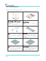
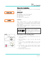
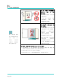
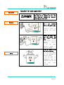
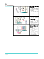
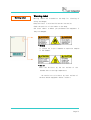
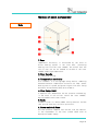
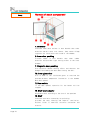
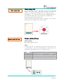
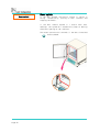
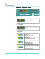
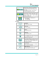
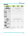
OPERATING INSTRUCTION [INCUBATOR] Model : IB-01E / 11E / 21E Manual No : 00HAA0001179 (Version : 5.0) This operating instruction describes the important subjects to maintain the product’s functions and to use it safely. Especially, be sure to read <Safety Precaution> carefully before you use this equipment. Please keep this instruction close to the equipment to use it after reading through it once. Please place it where the new user can find it easily for the safety use when you hand over or lend the equipment to others. Page 1 ■ Introduction Thank you for purchasing Jeio Tech’s product. This operating instruction forms a definition of warning marks according to the level of importance and danger in order to use the product safely and correctly and prevent the users from accidents or injuries. Hence, please use the product in accordance with the instructions. Page 2 Table of Contents Chapter 1: Manual & System Notice for the manual----------------------------------- 6 Warning mark for safe operation ------------------------ 6 Notice about reconstruction of the equipment ----------- 7 Exemption for responsibility---------------------------- 7 System construction------------------------------------- 8 Chapter 2: Installation & Checking Unpacking and transportation checking ------------------ 11 Units and accessories ---------------------------------- 12 Checking for installation ------------------------------ 13 Chapter 3: Warning & Caution for safe operation Warning for safe operation ---------------------------- 16 Caution for safe operation ---------------------------- 19 Warning label ----------------------------------------- 21 Chapter 4: Names of each component & Functions Names of each component ------------------------------- 23 Chapter 5: Display and Operating set Name and function of display ---------------------------- 28 How to set temperature---------------------------------- 30 Additional functions of TEMP key------------------------- 32 How to set timer --------------------------------------- 33 How to set and perform Auto Tune function----------------- 35 Lock function ------------------------------------------ 35 Page 3 Chapter 6: Maintenance and Troubleshooting Maintenance ------------------------------------------- 37 Safekeeping and Cleaning ------------------------------- 38 Troubleshooting ---------------------------------------- 39 Chapter 7: Specification Specification ------------------------------------------- 43 Chapter 8: Warranty & Service Warranty Standard -------------------------------------- 45 Service Contact ----------------------------------------- 46 How to waste ------------------------------------------- 47 Page 4 Chapter 1 Manual & System Thanks for purchasing our incubators (1) This Incubator is used for cultivation of thermopile micro organism and normal micro organism like e-coli and bacteria. (2) This Incubator is used for tissue of plant and animal, activating sperm and egg and determination of germfree of sterilized culture medium. (3) This Incubator is good for constant temperature test like test of plant storage, environment variation. Chapter 1 includes as below Notice on manual Alert for safe operation Notice about reconstruction of the equipment. Exemption from responsibility. System construction Page 5 Notice for the manual 1. Always keep this manual near to the instrument. 2. Check the manual in detail for correct operation 3. This manual is only for instruction of how to operate the instrument. Therefore, anything out of the contents of the manual is not guaranteed. 4. It is prohibited to print and distribute the manual partly or entirely without leave. 5. Please contact where you purchased the instrument if faults are found in the manual. Warning mark for safety operation 1. The warning marks are for safety operation and protect user and instrument from damage. 2. Each mark is identified following to the degree of risks or importance. “ Warning” means that the user may have serious damage and even die by improper handling on this unit. “ Caution” means that the user may have minor damage and unit may have physical damage by improver handling on this unit. Protective ground terminal. It marks the terminal must be connected ground prior to operating the product. It marks additional information on the operation and features of the product. 3. Pay attention to the contents of alert marks. 4. Specially important “ Warning marks” are attached on the main body.(On the door) 5. Please change the warning marks if they are worn out. ☞ Ask warning marks to where the instrument is purchased from if they are needed to be replaced. Page 6 Notice about reconstruction of the equipment 1. Read the manual carefully for safety before starting to operate the instrument. 2. Any damage which is happened due to carelessness is out of the manufacturer’ s responsibility. 3. It’ s prohibited to alter the instrument. 4. Departing, fixing, and altering the instrument at your will can cause electric shock, fire, and dysfunction. 5. Please contact where you purchased the instrument when some necessary parts should be changed. 6. External shock to this instrument can cause damage and dysfunction. Exemption for responsibility 1. Any claim which is out the quality guaranteed by the manufacturer is our of the manufacturer’ s responsibility. 2. Any damage which is from unexpected fault or damage of user by Acts of God is out of Manufacturer’ s responsibility. Page 7 System construction CLS(Custom Logical Safe)-Control System CLS-Control System, which means ‘a controller that has product specific safety features’, is the safest controlling device to be developed by Jeio Tech researchers. It is used to make products with heaters safer in environments that require perfect safety against heat, ie:-where flammable chemicals are used. (Patent No.0397583, No.0328729) CLS-Control System - Operation The power supply for main components within the machine is isolated. The magnetic contact switch is used to intercept all phases of electric power source, and stays with only the earth/ ground connected. It indicates to the user the error code visually or by auditory devices It sets off visual and auditory alarm for the users to acknowledge, even after natural recovery, and will stop the operation until the user identifies and solves then cause of the problem. CLS-Control System – Trouble shooting of damage on contact point. The connection point of the high risk sensing device used in the CLS-Control system set to permit only low voltage electricity (5V, 10mA) to flow, so that there is minimal damage to the contacts. In addition when the safety system is operated, it stops the thyristor that supplies current to the heater and isolates the magnetic contact switch to prevent damage and solenoid noise. Safety Machine stops automatically if the temp inside the chamber is over the ‘ Over Temp. Limit. This protects user and machine from sudden inflammable accident. When the door is opened, Door LED is flickering and blower and heater stops operating and alarm sounds 1 min. later. Machine is protected from over voltage or heater overload Page 8 Inner air leaking protection Specially designed silicon packing is attached on the chamber for perfect sealing and magnetic packing is attached on the door for dual air leaking protection. Easy UI(User Interface) and user design. PID Controller Temperature can be perfectly controlled by PID controlling way. All functions are shown on the display and operating process can be monitored. Auto-tuning function for exact temperature controlling and Bias function for compensating temperature deviation are installed in the controller. Wait On/Off function Heating can be automatically programmed by timer function. Shelf Maximum 11~15 ea of shelves can be put on the shelf level adjuster(30mm between shelves) Users can purchase additional shelves. Model IB-01E IB-11E IB-21E Max. No. 11 14 15 Intervals 30mm 30mm 30mm Page 9 Chapter 2 Installation & Checking Some damages on the equipment can be happen while transportation. Please check carefully if there are any damages on the equipment to get warranty service. In addition, electric safety should be confirmed before installation. Chapter 2 includes as below Page 10 Unpacking and transportation checking. Units and accessories. Checking for installation. Unpacking and transportation checking Incubators are delivered after strict QC and strong packing material and careful transportation controls are performed not to make any damages on them. Checking damage Claims Checking damages 1. 2. 3. 4. Check the packing condition before unpacking it. Unpack it carefully. Check if there are any damages on it while transportation. Check all the parts and accessories. (Refer to page 12) Claims Keep the equipment carefully if there are any damages found and contact the transport agent for checking. 1. Contact the agent and confirm the damage for warranty service. 2. Issue claims immediately for warranty service. 1. Do not throw away all the packing materials before confirming all the damages by agent. Damage regulations on transportation Damage regulations on transportation 1. Responsibilities for damages happened while transportation is up to transporter. 2. Any damage except for periods of transportation will be dealt with by the manufacturer. 3. The instrument which is not transported by manufacturer’s entrusted transporter is out of manufacturer’s responsibility The weights of incubators are about 30 ~ 60kg. Unload it by using carrying tools. At least 2 persons for carrying it. Page 11 Units and accessories Check the contents below after unpacking it. Request to the transport agent if there are any missing parts. Main equipment (IB-01E, 11E, 21E) Check if there are any damages after unpacking it. Check the assembling condition. Fuse Fuses are included in the packing. Additional ones are available by agents. Shelf 2 ea are included in the packing. Put them on the shelf rack. Additional ones are available by purchasing. Page 12 Operating manual Check the packing. manual is included in the Shelf Rack Hang it on the shelf level adjuster. 4 ea are included in the packing. Additional ones are available by purchasing. Perforated Shelf Not included in the packing as this is option. Samples unacceptable on wire shelves can be tested. Check for installation. Check the below points for installation on safe and proper environment. Check points Check points Location Location. Environment of the installing place. Checking while connecting power. Checking fuse. Checking after installation. Location Select proper location to install the equipment with installing agent. Installing agent should follow the manual for safe installation and operation. Users should follow the agent’s advice. Do not install the equipment where inflammable materials and organic gases are used. Keep advice from the installing agent when selecting installing location. Check electric and fire condition with agent. The equipment should be operated on optimal condition. Environment of the installing place 1. Install the equipment at plat ground and be careful not to be broken. 2. Keep the equipment at least 1.5m from light and 20cm from walls. 3. Do not install the equipment where noise or high frequency is emitted by other devices as coffee pot, heaters. 4. The environment of the installing place should be about 18℃ ~ 25℃ under 80%RH and do not install stove or heater near to the equipment. 5. Be careful while transportation. Page 13 Check the plug of the equipment whether it’s fit with the supplying power. The deviation of the voltage supplied to the equipment should be within +/- 10%. Checking while connecting power Check the ID plate attached on the side of the equipment before connecting power. Electric requirement 1. 2. 3. 4. 5. Code No. Description Model Voltage Serial No. Checking Fuse Model IB-01E IB-11E IB-21E Fuse Rating AC 100V AC120V AC 250V, 3A AC 250V, 8A AC 250V, 8A AC 230V AC 250V, 2A AC 250V, 3A AC 250V, 3A The equipment does not work properly and fire can happens if the connection is wrong. Check the ID plate in detail before connection. Checking after installation 1. 2. 3. 4. Page 14 Check whether the connection of plug is ok. Check whether the grounding wire is earthed correctly. Check whether the space is enough for installation. Operate the equipment after checking the safety point carefully. Chapter 3 Warning & Caution for safe operation “ Warning” means that the user may have serious damage and even die by improper handling on this unit. “ Caution” means that the user may have minor damage and unit may have physical damage by improver handling on this unit. “Alert Signal Words” are shown in the manual for safe operation. “Symbol Marks” are followed for each word. User should be careful for safe operation even though the equipment got IEC 61010-1 standard for electric safety and 89/336/EEC for electromagnetic wave guide. “Warning” case can cause serious damage to user’s life and property. Check the manual carefully before installing the equipment not to make any accident. Operate the equipment after checking the electric safety carefully. User should check all the possible dangerous elements to prevent accidents from happening. “Warning” and “Caution” describes electric safety while operation. Labels for alert are attached on the equipment for notice. Don’t waste it. Page 15 Warning for safe operation Installation “ Warning” means that the user may have serious damage and even die by improper handling on this unit. Electric Check voltage, phase, and capacity carefully Before connection. ☞ Wrong connection can cause fire or electric shock. ☞ Connect the power cord to outlet with ground terminal. Don’t connect many cords to one outlet. ☞ Overloading the capacity can cause fire or electric shock. ☞ the power should be connected to the separate outlet. Use power which is put to earth. ☞ No earth can cause serious damage to equipment and body. Never earth to gas or water pipes. Check the power and frequency on the ID plate attached on the side of the equipment before installation. ☞Use wire of more than SQ for 230V, 10A. The installation should be performed by parties which are authorized by Jeio tech Co., Ltd. ☞ Installation by unauthorized parties can cause fire or damage on the properties, casualties. It’s necessary to check the equipments on the agent’s site periodically. Page 16 Safty Do not install the equipment where gases can be leaked and exploded ☞ It can cause fire or explosion. Put the plug out if there are strange sounds or smell, smoke. ☞ Ask after service. ☞ It can cause fire or electric shock. Operation Safty Do not expose the equipment to direct rays of the sun. ☞ It can cause fire or damage on the equipment. Set the instrument apart from wet materials. ☞ It can cause dysfunction of the instrument and electric shock. ☞ Please ask After Service if the instrument is wet. Do not disassemble or change the equipment voluntarily. ☞ It can cause fire or electric shock. ☞ It can cause malfunction to the equipment. ☞ Use the equipment only for its purposes. Page 17 Do not keep materials inflammable near to the equipment. ☞ It can cause fire and explosion. ☞ Do not install the near to equipment dangerous areas. Do not put explosive or inflammable materials in the chamber. ☞ The materials can be exploded in the chamber. Explosive Acetic Ask parties who are authorized by Jeio tech related problem happens ester, Nitro compound. Inflammable materials: Salts peroxide, Inorganic if safety materials: acid, peroxide, acetate, brassware solvent. ☞ The equipment is not explosion proof. while operation. At least 2 persons should carry the equipment ☞ The weight of the equipment are between 30kg and 60kg. At least 2 persons should carry the equipment. ☞ Use proper tool for safe transport. ☞ Be careful not to be damaged while transportation. Page 18 Caution for safe operation Operation “ Caution ” means that the user may have minor damage and unit may have physical damage by improver handling on this unit. Electric Don’t put anything heavy on the power code. ☞ It can electric peeling cause shock the by cover off. Connect the plug tight into the socket and don’t touch it by wet hands. ☞ It causes fire by unstable electric condition. ☞ It can cause electric shock or physical damage. Do not put water on the body while cleaning. Safty ☞ It can cause damage to the equipment or electric shock. ☞ Put the power off immediately when the equipment got wet and ask after sales service. Page 19 Don’t shock or shake the equipment ☞ It can cause damage or malfunction to the equipment. ☞ It can cause low efficiency and unclear test result. Don’t spray insecticide or flammable chemicals to the equipment. ☞ It breakage can cause of the equipment or electric shock and fire. Don’t clean the equipment with solvents. Use soft cloths for cleaning. ☞ It can cause fire or physical change of the equipment. ☞ clean the equipment with sponge or soft cloths soaked with neutral detergent. Page 20 Warning label Warning label Warning labels are attached on the body for informing of safety and danger. Keep the alerts in mind and follow the instruction. Check the position of the labels on the body. Ask extra labels to where you purchased the equipment if they are damaged. * Warning It informs not to put flammable or explosive samples in the chamber. * Caution Users can be burnt by the hot surface of the chamber due to the high temperature. ※ Be careful not to be burnt by inner surface of the door which equipped a heater inside it Page 21 The chapter 4 Names of each component & Functions Carefully read the safety precautions to learn the requirements for the features and the names of each component of the incubator. For the right use of the incubator and your targeted experiments, complete comprehension on the features and vital functions of the unit is required. The chapter 4 explains the details of the names of each component and the functions Chapter 4 includes as below; Names of each component Page 22 Body Over temp. limit Power Switch & Fuse Door switch Names of each component Body 1. Door Temperature uniformity is maintained by the built-in direct heating system in the front door, preventing heating loss from the inner chamber. Be careful that the skin of user can not be touched on surface of the inner chamber under high temperature. 2. Door handle For opening & closing 3. Temperature controller This incubator is a cutting-edge safety device, combining advanced features; Temperature correction for Temp. sensor, Heating control system and proven Digital PID Auto Tuning mounted a microprocessor(CPU) with software. 4. Over temp. Limit A separate over-temperature cut-out prevents overheating, in the event of out-of-limit status the inner chamber, warning audible and visual alarms. 5. Body Standard finish is a white powder coating external surface that provide excellent corrosion protection. 6. Power switch & Fuse The fuse prevents temporal over-current from the cabinet. In the replacement of the fuse, please check with an appropriate power supply. Page 23 Body Names of each component 7. Chamber Stainless steel work surface is more durable than other materials and will never rust. Heater, Temp. sensor & Temp. regulator are installed at the inside of the chamber. 8. Inner door packing Silicone rubber is more durable than other rubber materials and provides tight sealing effect to the inner chamber. 9. Magnetic door packing This maintains double sealing effect and shortens the damage from slamming the door when closing the door. 10. Inner glass door This is made of the reinforced glass to overview the specimen without temperature fluctuation in the chamber when door opened. 11. Door switch If the door opened, operation for the heater will be stopped. 12. Shelf level adjustor Adjustable shelf according to the size of the specimen 13. Shelf Stainless steel wire treated by ion polishing provides the Surface finish exterior, Page 24 easy is cleaning excellent and superior corrosion ventilation. resistance and Over temp. limit Over temp. limit Power switch & Fuse The system would cut out all heaters, giving out warning buzzer and over temp indicator pulsing on when the cabinet’s temperature reaches the over temp set point. Consequently, all the operation will be stopped because of the unstable conditions in the cabinet (overheating). Check and remove these conditions. Press the button Start/Stop once to go back to the normal operation after appropriate actions taken. Power switch & Fuse Power switch Main power ON/OFF switch. Fuse A safety device for preventing from the overcurrent runs in the cabinet. The fuse disconnected by the overcurrent should be replaced with use of a screw driver(-). Model IB-01E IB-11E IB-21E Fuse Rating AC 100V, AC120V AC 250V, 3A AC 250V, 8A AC 250V, 8A AC 230V AC 250V, 2A AC 250V, 3A AC 250V, 3A Page 25 Door switch Door switch If the door opened, CLS-control system is taking in acting automatically, pulsing on door indicator and stopping the heater. If the door remains oepned in 1 minute after door openings, the system will automatically keep on warning sound and lighting up the indicator. The normal operation will be back if the door closed and button pushed. Page 26 Chapter 5. Display and operating set Please, we recommend that operator learns functions and operation of display before using Incubator. We recommend that operator reads this at least 2 ~ 3 times and use the unit. Please, contact with agencies or Jeio Tech if you have any question with display and operation. Chapter 5 includes as below; Name and function of display How to set temperature Additional functions of TEMP key Advanced Temperature setting function Example of advanced temperature setting function Change temperature degree BIAS function How to set timer On Timer setting Off Timer setting Timer function Cancellation of Wait On/Off Timer function Power failure compensation function of Timer key How to set and perform Auto Tune function Lock function Page 27 Name and function of display 1. PV indicator Indicates the present value. 2. SV indicator Indicates the set value or remaining time of timer 3. Status LED Heater LED Indicates the heater output. Auto Tune LED Flashes during Auto tune function. Wait On Timer LED Indicates time delay on functon. ( The unit starts operation automatically when the time reaches time which is set.) Illuminates while operating. Wait Off Timer LED Indicates time delay off function. ( Timer starts operation when PV values reaches SV value. The unit stops operation automatically after set time.) Illuminates while operating. Page 28 Door LED When the door is opened, door LED flashes and the power from fan and heater is cut off. Buzzer goes off if the door is not closed more than 1 min. For continual operation, close the door and press start/stop key one time. Over temp. LED Indicates when chamber temperature excess over set point of Over temp. limit devie. (Physical setting). Once it starts working, Buzzeer and LED works. Run LED Indicates that the unit is working or not. ON : Working Off : No working 4. Keys Temp key for temperature setting. Timer key For Timer setting. Up key For increasing value. Down key For decreasing value. Enter key For completing and storing value after adjusting and setting value. Start/Stop key For starting operation or stop the unit. Or using the key to eliminate warning sound or LED, if the unit stops operating due to unexpected symptoms. Lock key Locks all keys. Press and hold Lcok key for 1 second to set or release Lock function. Auto Tune key Press and hold the key for 1 second to strat operating Auto Tune fucntion. Page 29 How to set How to set Temperature Temperature SV indicator ① Press TEMP key. ② Value on SV indicator blinks. ③ Adjust value by using UP and DOWN key. ④ Press ENTER key and finish temperature setting. ⑤ Press START/STOP key to start running. ☞ No key input for 10 secondis during temperature setting, you return to initial status. Nothing setting. Key operation flow Additional functions of TEMP key How to save set temperature Advanced Temperature setting function Set and save upto 3 different temperature as SV1, SV2, and SV3. The values can be select and recall if operator wants. ① ② Page 30 Press TEMP key 2 times continuously. SV1 shows on PV indicator, value can be put on SV indicator. ③ Adjust value by using UP and DOWN key and press ENTER key to finish temperature setting. ④ The value is saved in SV1 and current set value is changed. ⑤ If press TEMP key one more time, SV2 shows on PV indicator and a different value can be saved by using UP and DOWN key. ⑥ If press TEMP key one more time, SV3 shows on PV indicator and value can be saved. Example function of advanced temperature setting How to use advanced saved temperature on SV1 : Press TEMP key 2 times. ① ② PV & SV indicator ③ SV1 shows on PV indicator and set point shows on SV indicator. Adjust value by using UP and DOWN key and press ENTER key to finish SV1 temperature setting. Press START/STOP key to control temperature saved on SV1. How to use advanced saved temperature on SV2 : Press TEMP key 3 times. ① ② PV & SV indicator ③ SV2 shows on PV indicator. Adjust value by using UP and DOWN key and press ENTER key to finish SV2 temperature setting. Press START/STOP key to control temperature saved on SV2. How to use advanced saved temperature on SV3 : Press TEMP key 4 times. ① ② PV & SV indicator ③ SV3 shows on PV indicator. Adjust value by using UP and DOWN key and press ENTER key to finish SV3 temperature setting. Press START/STOP key to control temperature saved on SV3. Page 31 How to change temperature unit The temperature unit changing function Temperature unit shows on SV indicator and it can be changed deping on customer preference. Press Temperature key 5 times. ① ② ③ BIAS function BIAS - Compensates temperature difference between reference sensor and equipped sensor in unit caused by temperature sensor or other reasons. - Please put a reference sensor at the center of the chamber inside and wait for 5 minutes at least after your reference sensor is stabilized. - Press TEMP key 6 times. ① Please use certified ② thermometer as your reference sensor. PV/SV 표시창 Please, call service or contact agencies if the temperature difference is same even performing BIAS . Page 32 Factory defualt value is set Celceous degree. (℃) Press UP and DOWN key and change the value to Ferenheit degree.(℉) Press ENTER key to finish setting. after ③ BAIS shows on PV indicator and actual temperature inside chamber shows on SV indicator. Input the difference between your reference sensor and actual temperature inside chamber by using UP and DOWN key. Press ENTER key to finish BIAS function and press START/STOP key to start operation. How to set Timer ON Timer On Timer setting PV & SV indicator LED status OFF Timer Press TIMER key 1 time. Type of Timer shows on PV indicator and time shows on SV indicator. ( ON Timer is set at the left side, but it might not be ON Timer set, if you set Off Timer before.) ① Input time by using UP and DOWN key and press ENTER key. ② W/ON LED blinks, which means that the function starts. Off Timer setting Press TIMER key 2 times and Off Timer can be set. PV & SV indicator ① Input time by using UP and DOWN key and press ENTER key. ② W/OFF LED blinks, which means that the function starts. LED status Timer function Timer function ① Wait on Timer The unit works automatically after lapse of time at On Timer function. Max : 99hour 59minute, Min : 1minute. Page 33 ② Wait off Timer Timer starts when actual temperautre reaches set point. And the unit stops after lapse of time at Off Timer. ③ Both Wait on Timer and Wait off Timer. Both Timer can be set at the same time and it shows the graph on pase 33. Timer cancel Cancellation of Wait On/Off Timer function. ① ② Cancellation of Wait On Press TIMER key 1 or 2 times. Set time as 0 (Zero) and press ENTER key. (cf) W/ON, W/OFF LED is off and each Timer function can be cancelled only press ENTER key without any adjustment at ②. Cancellation of Wait Off Auto run Power failure compensation function of Timer key Press TIMER key 3 times. This function is Power failure compensation function. If YES is set, the unit starts automatically when power recovers after power failure. Auto Run setting ① Cancellation of Auto Run Page 34 Yes or No can be set by using UP and DOWN key. Auto tune How to set and perform Auto Tune function Auto tune function makes the unit better control response. When Auto tune function needs; A. Temperature fluctuation. B. It takes too long to reach set point. ① ② PV/SV indicator Auto Tune can work during unit working if you press and hold A/T key for about 1 second. Auto Tune shows on PV and SV indicator. ③ ④ LED status ⑤ Set temperature. (refer to page 30.) Press and hold A/T key for 1 second and Auto tune shows on PV and SV indicators. And A/T LED blinks, which means Auto tune function starts. Press START/STOP key and RUN LED blinks, which means that Auto Tune starts. Once Auto Tune is finished, A/T LED is off and temperature controls. Auto Tune takes tens of minutes or some hours. Please, do not turn off main switch during Auto Tune. Recommend please, perform Auto Tuning at the first use of the unit. Also after long period of time, unit needs Auto Tune. Lock function Lock function All keys do not work. ① Press and hold Lock key for 1 second and “ Lock” shows on PV indicator with Beep sound. And all keys do not work any more except Lock key. ② To release keys lock, press and hold Lock key for 1 second. Lock setting Page 35 Chapter 6. Maintenance and Troubleshooting The incubator would be maintained on the best condition by check the functions and state periodically. In addition to prevent of pollution of culture fluid or samples that could be occurred during tests. The chapter 6 illustrates trouble that could be occurred operating the unit. Please request the service refer to this operating manual when trouble occurs. Chapter 6 includes as below; Maintenance Weekly / Monthly / Quarterly / Annually Safekeeping and Cleaning Safekeeping way/ Exterior cleaning / Interior cleaning Troubleshooting Main power Temperature control Page 36 Maintenance Weekly Weekly Clean all interior and exterior surfaces, interior shelve and shelve gasket with cleaner and then dry. Easy to remove the shelve gasket and shelve level adjuster for cleaning in Auto clave. Loose top and bottom bolts in shelve level adjuster. Check the door movement and seal. Check the temp control, accuracy and uniformity Do not clean the surface of incubator with sulfuric acid, hydrochloric acid or organic solvent. It may deteriorate the ability of the product. Monthly Monthly Check the main power and plug. (Refer to the chapter 2 “installation”) Check that the setting values and are correctly inputted to press the buttons. Quarterly Quarterly Make a routine check weekly/ monthly. Check the functions of the controller. Annually Annually Make a routine check monthly/annually. - Check the incubator function. - Check the electric source. Follow the safekeeping way and maintenance standard to care for the unit so that, keep the best condition and quality of the unit. Page 37 Safekeeping and Cleaning Safe keeping Safe keeping way If the incubator is not used for a while, maintain as follow. 1. 2. 3. Exterior cleaning Exterior cleaning 1. 2. Interior cleaning Please take off the plug to turn off the power switch. Maintain the unit with packing to prevent dust inserting interior and exterior. Pack the incubator completely to avoid from dust. Clean up the body using a soft cloth with neutral detergent. Wipe with a dry cloth the controller and outside. Interior cleaning 1. 2. 3. 4. 5. 6. Please turn off the power switch Take off the shelf, shelf level adjuster and Shelf bracket. Loose the upper and downer bolt from shelf level adjuster. Clean up the interior using a soft and wet cloth with neutral detergent. Be careful to damage the sensor during cleaning. Clean up the body using a soft and wet cloth. Wipe with a dry cloth Cleaning the interior of unit may cause damage on system or any other parts. Be carefully clean up the interior of unit. Page 38 Troubleshooting If any trouble occurs by operating the unit, please follow the bellow directions. If the existing solutions will not solve problems or does not exist, please request the service immediately. Trouble related with main power Trouble Causes The unit does not turn on. Circuit breaker is often shorted Circuit breaker of building(room) is often shorted Solution Connecting incorrect electric outlet. 1. Check correct power and Damaged Power, outlet or voltage of the ID plate circuit breaker sticking on the back side of Connecting overload concent. the unit. Circuit braker shuits down or 2. Find out the causes of black out. power failure and recovery. 3. Insert the main power plug correctly. 4. Use a separate outlet to supply the power. 5. Repair cased blak out 6. If the problems do not solve, request the service. The fuses do not fit the main 1. Check voltage (V) and power. Ampere (A) of fuses. The main power might be cut (Refer to the chapter2 or a parted “ Installation” ) Humidity might inflow into the 2. If main power is cut of main power inserting part. aparted, exchange it. 3. If there is humidity on the inserting part, clear it and reconnect. 4. If the problems do not solve, request the service. Too many plugs connect at 1. the same time. 2. 3. Check voltage suppleid by circuit breaker. Check that several simialr units are inserted together, if so you sould not use overly. If the problems do not solve, request the service. Page 39 Trouble Causes Solution Main switch lights on but display does not show Main plug does not insert correctly. The lamp of the main switch doesn’t light on. Controller trouble. 1. Check there might be blackout. 2. Main plug connects with socket correctly. 3. If the lamp of main switch doesn’t light on, it may be poor switch.. Please replace main switch 4. If the problems do not solve, request the service Whole controlling of the unit stops without cutting main power or any buttons Might be influenced a strong noise. 1. Avoid from the unit producing a strong noise or put away that. 2. If the problems do not solve,request the service. Trouble related with Temperature Trouble Causes Incubator doesn’ t operate while pressing START/ STOP button. While operating timer function 1. Press Timer button. And then, press Enter button after make 0(Zero) in Wait on Timer, Wait off Timer function. 2. Request the service to replace the controller. Temperature controll. doesn’ t Auto tune doesn’t operate. 1. Press Auto Tune to restart the incubator. 2. If the problems do not solve,request the service. Temperature increase. doesn’ t Run Led doesn’t light on. Door LED is illuminating. 1. Check the RUN Led for lighting on. If Run Led doesn’t light on, Press Start/Stop button. 2. Check the door LED. Close the inner door completley. 3. If the problems do not solve,request the service Page 40 Solution Trouble Causes Solution The beep sound rings. Trouble of the set value of over temp limit The inner door opens. 1. The set vaule of over temp limit is less than prsent set value. 2. Turn the red knob of over temp.limit until over temp limit 15% higher than the present set value. 3. Check that RUN LED lights on after pressing START/STOP button. 4. Check the door LED. If the LED lights on, close the inner door completely. 5. If the problems do not solve,request the service. Page 41 Chapter 7. Specification Confirm the incubator’s specification to check the unit’s functions. Read this to know its features and specification, so test to meet its property. Chapter 7 includes as below; Specification Page 42 Specification Model IB-01E IB-11E IB-21E Chamber volume 65L 150L 205L Temperature 5℃ to 40℃ Maximum relative humidity 80% Altitude up to 2,000m Permissible environmental condition Range Uniformity Amb.+3℃ ~ 60℃ ±1.0℃ at 40℃ ±0.6℃ at 40℃ Accuracy ±0.1℃ at 40℃ Heat up time 38℃ Within 40 min Controller Digital PID auto tuning Sensor type Pt 100Ω Temperature Internal External Shelves Insulation Door gasket Material Stainless steel, 0.6t Stainless steel, 0.8t Steel 0.8t, powder coating Stainless steel wire, electro polished Polystyrene(10t) Safety device Magnetic packing(door), silicone(inner door) Wait on time, Wait off time (Max. 99hr 59min, Min. 1min) CLS(Custom Logical Safe)-control system Over temp. limit Hydraulic over temp. limit Timer Carbon film 250W Carbon film 500W Carbon film 550W Internal(㎜) 423 X 355 X 445 500 X 515 X 585 632 X 515 X 630 External(㎜) 533 X 475 X 725 595 X 630 X 865 740 X 630 X 910 Heater Size (W×D×H) Electric requirement Power consumption AC100V, 50 Hz, 60Hz / AC120V, 60Hz / AC230V, 50Hz AC100V 2.5A 5.0A 5.5A AC120V 2.1A 4.2A 4.6A AC230V 1.1A 2.2A 2.4A 47Kg 57Kg Weight(net) 37Kg (AC 230V MODEL:33 Kg) ※ Above the options could be changed without any notice in accordance with the quality and efficiency improvement for the product. Page 43 Chapter 8. Warranty and Service Jeio Tech’s incubators can be protected by our warranty and service standard. Except for the presented standards, others would not be warranted. Chapter 8 includes as below; Warranty Standard General Matter Warranty exception Page 44 Service Contact How to waste Warranty standard 1. Customer can get free warranty service for 1 year from the date of purchase when the machine is broken while operating. 2. Customer can’t get free warranty service in case of as below. ① If the machine is broken due to the Act’s of God. ② If the machine is broken due to overuse of voltage ③ If there is some shock to the machine. ④ If the outer part is damaged by solvent ⑤ If the machine is broken without taking care of the “Notice” alerted on the manual. ⑥ If persons who are not under the authority of service of Jeio tech fixed or changed parts of the machine ⑦ If the broken machine is due to customer’s fault 3. Contact your regional dealer for after service. General matter The term of guarantee about responsibility on manufacture is 1 year from purchase work under. . * * * * Purchase date Serial Number A trouble part and trouble state Equipments use environment Warranty exception Charge within the term of warranty if as follows * A use of mistake of a user * A mistake of treatment of a user and custody * Unfair change of usage, remodeling of a machine and acceptance. * It is trouble y act of God such as a fire, a brilliant trouble by the use that it did not keep operation manual. Page 45 Service contact Service contact Korea (Head office-Overseas department) 4F Hosu B/D, 379-13, Seogyo-dong, Mapo-ku, Seoul, Republic of Korea (121-839) TEL: +82 - (0)2 - 3143 - 1823 / 1825 FAX: +82 - (0)2 - 3143 - 1824 http://www.jeiotech.com E-mail: [email protected] U.S.A. 2400 East Devon Ave, Suite 210, Des Plaines, IL 60018, USA TEL: 1-847-298-6613 FAX: 1-847-699-8487 E-mail: [email protected] China RM107, No.68 Line, 569 Xin Hua Road, Shanghai, China Postcode: 200052 TEL: 86-21-62940608 FAX: 86-21-62940602 E-mail: [email protected] South East Asia No.7A, Jalan Kemboja 1 B/2, 48300 Bandar Bukit Beruntung, Selangor Darul Ehsan, Malaysia TEL: 603-60285833, 603-60285825 FAX: 603-60285822 E-mail: [email protected] England (UK) Unit 33, Monument Business Park Warpsgrove Lane, Chalgrove, Oxfordshire OX44 7RW, UK TEL: +44-1865-400321 FAX: +44-1865-400736 E-mail: [email protected] Page 46 How to waste How to waste To waste main parts External dimension(mm) (WⅹDⅹH) Configurat ion Parts Model Main body IB-01E Main body IB-11E 47 595 X 630 X 865 Main body IB-21E 57 740 X 630 X 910 Gross Weight(Kg) 37 (230V MODEL:33Kg) 533 X 475 X 725 Contact a company which is dealing with waste parts. Page 47


![livret d`accueil dessins [Mode de compatibilité]](http://vs1.manualzilla.com/store/data/006520297_1-78e0ac2079a955e9a570bb2a41a01c4d-150x150.png)