1
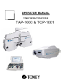
OPERATOR MANUAL TOMEY REFRACTION SYSTEM TAP-1000 & TCP-1001 Read this instruction manual carefully before using this instrument to ensure correct and safe operation. If you have questions about operations, please contact Tomey GmbH or our local distributor. Always follow the operation procedures described in this manual Keep this manual in a readily available location while operating the instrument Contact our local distributor if you lose this instruction manual 1 ~ Alternating current circuit Protective earth (ground) Attention, consult ACCOMPANYING DOCUMENTS Off (power : disconnect to the mains) On (power : connection to the mains) 2 Index 1 2 3 4 5 6 General Instructions 1.1 Important Safety Information 1.2 Prior to Use 1.3 Precautions for Operation Contents Installation 3.1 Junction Box 3.2 Connection with other Tomey Products 3.2.1 Connection Settings 3.2.2 Serial Interface 3.3 Data Protocol Structure and Function TAP-1000 4.1 Phoropter Head 4.2 LCD Display 4.3 Controller Keyboard 4.3.01 Keyboard Overview 4.3.02 Single test and chart selection / Controller for Chart Projector TCP-1001 4.3.03 Special tests / filters 4.3.04 Chart masks 4.3.05 Programm keys 4.3.06 Electronic Dial 4.3.07 Operation Field 4.3.08 Data keys 4.3.09 Conversion keys 4.3.10 Refraction mode keys 4.3.11 Function keys 4.4 Contrast Adjustment of LCD Printer / Print out Set up / Main Menu 6.1 Date and Time 6.2 Chart Type 6.3 Setting up Auto-Ref-Keratometer 6.4 Setting up SPH 6.5 Setting up CYL 6.6 Setting up AXS 6.7 Polarizing Filters 3 5 5 6 6 7 8 8 9 9 9 10 13 13 15 16 17 18 19 20 20 21 21 23 24 25 25 26 26 27 27 27 28 28 28 29 29 7 8 9 10 11 12 13 14 6.8 Setting up Speed 6.9 Communication Speed 6.10 Auto OFF time for LCD 6.11 Programming 6.12 Other Information Troubleshooting Specifications TAP-1000 Structure and Function TCP-1001 Installation 10.1 Positioning of Projection board 10.2 Focus Adjustment Remote Control Chart Projector light source 12.1 Replacement of Bulb 12.2 Replacement of Fuse Specifications Maintenance 14.1 Warranty 14.2 Disposal 4 29 30 30 30 31 32 33 34 36 36 37 37 38 38 39 40 41 41 41 1 General Instructions 1.1 Important Safety Information Do not install this instrument in a location where explosive or inflammable substances are used or stored. Otherwise, fires or explosion may occur. Do not remove the cover of the instrument. Otherwise, you may be directly exposed to high voltage sections. Do not disassemble or modify the instrument. Otherwise, you may be directly exposed to high voltage sections. Disconnect the power cord from the instrument before servicing it. Otherwise you may get an electric shock. Do not place water or chemicals on the instrument. Any water or chemicals entering the instrument may cause an electric shock or failure. Only use the specified terminal for connection of the instrument. Using another type of terminal may result in failure of the instrument. Fix the equipment strongly because the parts are heavy. This instrument is a measuring device specially designed for optometry and ophthalmology. Never use the instrument for other purpose. 5 1.2 Prior to use 1.3 Read this manual thoroughly before using the instrument to ensure proper and safe operation. Always follow the operation procedure described in this manual. Check that there is no device that generates strong magnetic field near the instrument which may cause noise and affect the measurement. Precautions for operation This system should not be used in an area where the temperature falls below 10°C or exceeds 40°C. Do not put or use the device in humid rooms. Humidity should be maintained between 30% - 75%. Do not place containers containing fluids, liquids or gases on top of any electronic equipment or devices. Customer maintenance of this equipment may only be performed as stated in the User and Service Manual. Any additional service may only be performed by your local distributor or authorized persons. Tomey is not liable for damage caused by unauthorized persons tamper with the system. Keep this User Manual in a place easily accessible at any time for persons operating the equipment. Do not force cable connections. If a cable does not connect easily, be sure that the connector is appropriate for the receptacle. Please do not pull on any cable. Always hold on to the plug when disconnecting cables. This equipment may be used for the international application related to several tests as visual acuity, astigmatism, phoria or stereo vision according to this manual. 6 2 Contents - Phoropter head - Controller keyboard - Junction box - Connection cables / Power plug - Reading rod (cm, inch, Diopter scale) - Reading chart - 2 Magnetic eye shields (additional) - External Printer - Dust cover - Chart Projector - Remote Control - Projection board (410 x 280cm) - Adapter for projector mounting - Projector table mount - Dust cover - Operator manual - Bulb + spare bulb and fuse 7 3 Installation As a standard, the TAP-1000 is integrated in an examination unit and switched ON and OFF via this unit. A main plug for the system is located on the junction box. The TCP-1001 has a separate ON/OFF switch but can be controlled via the examination unit as well. Do the installation of the system step by step: Make sure not to do the installation while the junction box is plugged 1. Check the contents listed in (cap 2) and prepare them for the installation 2. Mount the phoropter head at the corresponding phoropter holder of the examination unit 3. Connect the phoropter head to the junction box with the interface cable (8-pin) 4. Connect the controller keyboard to the junction box with the 9-pin connection cable 5. Mount the chart projector TCP-1001 according to the conditions of the examination unit and connect it with the junction box (2-pin). Refer to (cap 10) for adjustment and positioning of the device 6. If required mount the external printer to the examination unit and connect it with the junction box (4-pin) 7. Before connecting the power cord to the junction box check the voltage setting of the backside of the box and plug the power cord to the electricity network 8. Turn on the power of the chart projector TCP-1001 9. Wait until the TAP-1000 finishes the initialization procedure 10. Check the LCD display of the controller keyboard and adjust the contrast (cap 4.4) 3.1 Junction Box 8 3.2 Connection with other Tomey products For objective data input the refraction system can be easily connected with several Tomey products - TL-2000B, TL-3000B or TL-5000 - TR-4000 or RC-5000 3.2.1 Connection settings TL-2000B TL-3000B TL-5000 TR-4000 RC-5000 Æ Æ Æ Æ Æ TOMEY LINK TOMEY LINK COM No special settings Phoropter form 3.2.2 Serial interface Baud rate Data length Parity Stop Bit Flow control Æ Æ Æ Æ Æ 9600 8 bit NON 1 NON 9 3.3 Data protocol 10 11 12 4 Structure and Functions TAP-1000 4.1 Phoropter Head Front side 1 2 3 4 ① Fixing grip for near vision rod ② Fixation for near vision rod ③ Forehead rest controller ④ VD control window 13 Back side 6 5 7 8 9 ⑤ Level controller grip ⑥ A level ⑦ Forehead rest ⑧ Test aperture ⑨ VD control scale 14 4.2 LCD Display Displays several information/values - objective refraction data (Auto-Ref-Keratometer, Lens meter) SPH,CYL, A - subjective refraction data SPH, CYL, A, ADD, PRISM, VA - main axis selection for cross cylinder alignment 0°, 45°, 90°, 135° - retinoscopy lens function key R/L +2.00D (0.50m), +1.50D (0.65m) - temporary setup for cylinder axis 1°,5° - display of temporary chart - display of main setup and corresponding function keys for temporary and permanent settings 15 4.3 Controller Keyboard 1 10 9 8 2 11 7 4 6 3 5 1) LCD 3) Chart mask 5) Electronic dial 7) Data key 2) Single test and chart selection 4) Program key 6) Operation field 8) Conversion key 9) Refraction mode key 11) Contrast Adjustment LCD 10) Function key 16 4.3.1 Keyboard Overview 17 4.3.2 Single test, chart execution and controller for chart projector E This part of the controller keyboard is used for test and chart selection and for operating the chart projector TCP-1001. Further tests as Schober, , Worth 4 Dot and a single E for VA 0.05 are available. You can easily activate the tests by pressing Shift and the corresponding test button at the same time. The standard charts are presentable in the following visus scales - Numbers - Letters - Snellen - Pictures LAMP OPEN R/G 0.1, 0.15, 0.2, 0.3, 0.4, 0.5, 0.6, 0.7, 0.8, 0.9, 1.0, 1.2, 1.5 0.1, 0.15, 0.2, 0.3, 0.4, 0.5, 0.6, 0.7, 0.8, 0.9, 1.0, 1.2, 1.5 0.1, 0.15, 0.2, 0.3, 0.4, 0.5, 0.6, 0.7, 0.8, 0.9, 1.0, 1.2, 1.5 0.2, 0.4, 0.6, 0.8, 1.0 switch lamp of chart projector ON/OFF opens chart projector lens and displays no chart Red/Green mask available for standard charts 18 4.3.3 Additional to the standard chart selection several special tests which are needed for current refraction procedure Dissociated phoria test Polarization chart Schober-Test Suppression test Red-green chart Associated phoria test Polarization chart Worth 4 dots test 4 dots chart Corrected astigmatic axis and Diopter accurate test Dot chart Maddox rod test Dot chart Stereopsis test Polarization chart Aniseikonia test Polarization chart Eyes balance test Polarization red-green chart Eye balance test Polarization numeral chart Filter and auxiliary lenses available in the TAP-1000 - Polarizing Filters Æ 45° left/right, 135° left/right - Maddox Æ vertical/right, horizontal/left - Red/Green Filters Æ red/right, green/left 19 4.3.4 Chart Mask The controller keyboard allows to select several masks over chart of optotypes. - single mask - horizontal mask - vertical mask the mask can be moved up, down, right, left by pushing the corresponding button masks can be used for optotypes only press selected mask to activate or deactivate it 4.3.5 Program key - This function offers four optional program sequences A,B,C,D - Press here for programm start and performance - Select A, B, C or D by pressing the START button several times - The programming can be done in the main setup (cap 6.11) 20 4.3.6 Electronic Dial It is used to change the value of - SPH - CYL -A - ADD - PRISM - PD 0.25D / 1.00D / 2.00D / 3.00D step 0.25D / 1.00D / 2.00D step 1° / 5° / 10° / 15° / 20° step 0.25D step 0.1Δ / 0.2Δ / 0.5Δ / 1.0Δ / 2.0Δ step 1mm step Turn right Æ Change to Turn left Change to Æ 4.3.7 Operation field Cross cylinder The TAP-1000 supports the examination with cross cylinder ± 0.25D for - Cylinder power adjustment - Cylinder fine adjustment - Axis adjustment The cross cylinder can be used with standard charts (Numbers, Letters, Snellen) and with the Dot chart You can swivel in the cross cylinder lens with the XC1 and XC2 button only in the cylinder C and axis A mode. Select the chart which should be displayed for the cylinder/axis adjustment before you activate the cross cylinder. As soon you select a new chart the cross cylinder lens swivelled out. 21 Cylinder power adjustment / 1-2 questioning: Select the cylinder mode C and press XC1 to start cylinder power adjustment. The cross cylinder axis is perpendicular to the cylinder axis and the cylinder power is reduced. If you press XC2 the cross cylinder axis is parallel to the cylinder axis and the cylinder power is increased. Change the cylinder power according to the better position. The spherical power will be adapted automatically (CYL ±0.50D Æ SPH± 0.25D) Cylinder axis adjustment / 1-2 questioning: Select the axis mode A and press XC1 to start cylinder axis adjustment. The “+” cross cylinder axis is 45° to the cylinder axis. Press XC2 and the “–“ cross cylinder axis is 45° to the cylinder axis. Change the cylinder axis according to the better position. Numeric input buttons On the one hand the buttons are an indicator for the corresponding direction In which you have to turn to increase or decrease the values. On the other hand You can change values in the active mode by pushing the buttons directly. According to the mode which is active you can change following values - SPH - CYL -A - ADD - PRISM - PD ±0.25D step ±0.25D step ±1° / 5° step ±0.25D step ±0.1Δ / 0.2Δ step ±1mm step SHIFT + SHIFT + SHIFT + “+”/”-“ 1.00D / 2.00D / 3.00D step “+”/”-“ 1.00D / 2.00D step “+”/”-“ 10° / 15° / 20° step SHIFT + “+”/”-“ 0.5Δ / 1.0Δ / 2.0Δ step You can optional change the steps with the SHIFT button. The increment of each value can be changed in the main settings (cap 6) 22 Eye selection button R you can set and change the values for right eye, left eye is covered L BIN you can set and change the values for left eye, right eye is covered you can set and change the values for both eyes 4.3.8 Data keys - used to input external data into TAP-1000 - the data of selected and active mode are displayed in the middle of the LCD screen - the selected mode (RM, SUBJ, FINAL) is displayed top left in the main window IN RM to input objective data (lens meter, ref-kerato-meter) to controller objective data from refractometer/lens meter are displayed in the top right/left window on the LCD. The corresponding data are automatically adjusted in the phoropter and can be continued for use of the refraction. UA used to get unaided VA. Lens should be 0.00D SUBJ after communicating with lens meter, ref-kerato-meter it’s in this mode automatically. This values can be displayed during the refraction process in the according small window on the right and left side of the LCD. Could be used for comparison of previous and new refraction data. It can also be used to adjust the data, sent from lens meter or ref-kerato-meter, in the phoropter for further steps. FINAL press this button when the refraction process is finished. Always the last values can be marked as final and used for comparison with objective values. SHIFT used to select additional charts and to activate the settings in the main setup (numeric input, electronic dial, conversion key) 23 4.3.9 Conversion key ESC used to cancel a setting in the menu MENU used to set up the menu. EXE confirms the setting in the menu used for changing parameter or program input F/N to select F far or N near mode - selected mode is displayed on top right of central screen - basic setting is F far mode - ADD is only available in N near mode - ± 0.5D cross cylinder lens for N near mode - press 5th function key PD to activate pupil distance adjustment 50 – 80 mm (N 35 – 70mm) BI ↔ BO use this to input the absolute value of the polar coordinates or IN/OUT of rectangular coordinates BD ↕ BU use this to input the angle of the polar coordinates or UP/DOWN of rectangular coordinates right/left test aperture is covered right/left Pin hole ( Ø 1mm) swivels in SHIFT + right/left test aperture is opened (right) 6ΔBU are on the right aperture SHIFT+ (left) 10ΔBI are on the left aperture SHIFT+ 24 4.3.10 Refraction mode key - use this buttons to activate the corresponding mode you have to adjust - the active mode is displayed in black on the LCD screen - values can be changed by the numeric input buttons or the electronic dial - use the SHIFT button to change the step according to your need S C A ADD VA 4.3.11 used to change the sphere SPH used to change the cylinder CYL SHIFT + C change to + or - cylinder lenses used to change cylinder axis used to change Addition ADD (only in N mode) you can input value of visual acuity VA Function keys Use this keys to confirm or operate the displayed functions you can see on the LCD screen PRINT RESET you can print out the measured data or send the values to a local PC you can delete all data and do a reset before the next measurement 25 4.4 Contrast adjustment of LCD A potentiometer is located in the under part of the controller keyboard. Please use a small cross slot screwdriver to adjust the contrast of the display according to your needs. 5 Printer / Print Form The refraction system comes with a external printer. Please mount the printer by four screws on the under part of the refraction unit or table where you will place the system Please use the corresponding 6-pin data cable for connection. By pressing the PRINT button after the measurement you can print the subjective refraction data. Print form 2008-11-02 13:00:10 - 1.25 SPH - 1.50 - 0.75 CYL - 0.25 AXS 85 92 I 1.00 X I 1.00 D 0.00 Y U 0.00 PD 64.0 26 6 Set up / Main Menu 6.1 MENU button on the control keyboard to open the basic set up Use the up/down buttons to select the single modes and for changing several settings Use the corresponding function keys for selecting the indicated options on the lower LCD screen Date and Time Use the up/down buttons to select year, month, day , hour, minute or second. Press SET and change the setting with the up/down buttons again. Et the end press SET in order to save the values. 6.2 Chart type In the chart mode you will find a selection of four different chart types 700D 700A PCN PMC Please not that the recommended chart type is PCN PCN offers you additional charts by using the SHIFT button - Schober, E 0.05, Worth 4 Dot, Pin hole 1mm, 6ΔBU, 10ΔBI 27 6.3 Connection with auto-refractor/auto-ref-keratometer Select the corresponding setting with the function keys RMA PRK RK 6.4 Setting up SPH In this mode you can change the SPH steps. If you press SHIFT + / or use the electronic dial, the sphere lens changes according to your setting 1.00 2.00 3.00 . 6.5 Setting up CYL In this mode you can change the CYL steps. If you press SHIFT + / or use the electronic dial, the cylinder lens changes according to your setting 1.00 1.25 2.00 . 28 6.6 Setting up AXS In this mode you can change the AXS steps. If you press SHIFT + / or use the electronic dial, the axis of the cylinder lens changes according to your setting 5° 6.7 10° 15° 20° Polarizing Filter Use this mode to generate the setting of the polarizing filter of the right and left eye. Right eye 135° / 45° and left eye 45° / 135° 45° 6.8 50 135° Setting up Speed / Transfer Rate 55 60 65 70 75 Recommended SPEED should be at least 65 29 6.9 2400 Communication Speed 4800 9600 1920 5760 1152 . 6.10 Auto off time for LCD Screen Select the available time 5min, 10min or 15min 5M 10M 15M 6.11 Programming Select programm A, B, C or D Next step is to select the single charts/tests one by one. Save each chart/test and continue with the next one. Each programm allows you to save 50 different charts/tests. Use the DEL function to delete the single test while programming or the hole programm. 30 6.12 Other information REV : 3.10 Beep: NO . REV DIOPT Beep Software version Settings for after-sales service Feedback signal ON / OFF 31 7 Troubleshooting Before calling to service engineer If you have any problems, please check the list bellow. Please call your local distributor if you can not solve the problem. If the unit can not be operated even the electric power’s “ON”. Check if the electric power cable is connected with an outlet Connect the electric power cable correctly Set the brightness and contrast again There’s nothing displayed at all on the LCD Check if the cable is connected with the controller keyboard correctly Something on the displayed monitor is It is because of “Auto Off”. So please just press disappeared unexpectedly any key on the controller Any keys are not working Turn the switch off and on again When you can’t print out Replace print paper by new one or check if papers are jammed inside 32 8 Specification Measurement Range Spherical Lens -29.00D ~+26.75D (0.25D/1.00D/2.00D/3.00D step) Cylinder Lens 0.00D ~-9.75D (0.25D/1.00D/2.00D step) Cylinder Axis 0° ~ 180° (1°/5°/10°/15°/20° step) PD 50 ~ 80mm (Near Working Distance 35~70cm) Rotary Prism Lens 0 ~ 20Δ (0.1Δ/0.2Δ/0.5Δ/1.0Δ/2.0Δstep) Cross Cylinder ±0.25D Retinoscopy +1.50D (67cm), +2.00D (50cm) Visual Field 35° Auxiliary Lens Occ Pinhole Ø 1mm Maddox Rod Right Eye (Red, Horizontal) / Left Eye (Green, Vertical) Red / Green Filter Right Eye (Red) / Left Eye (Green) Polarizing Filter Right Eye (135°,45°) / Left Eye (45°, 135°) Split Prism Right Eye (6ΔBU) / Left Eye (10ΔBI) Cross Cylinder Lens ±0.50D (Fixed with the axis set at 90°) Dimension Head 450(W) X 308(D) X 131(H), 6.8kg Controller 230(W) X 268(D) X 152(H), 1.1kg Thermal Printer Printing Wide 48mm / Paper Wide 58mm Power Source AC 110~120V / AC 220~240V Power Consumption 120VA 33 9 Structure and Functions of the TCP-1001 The TCP-1001 is operated by a remote control or the controller keyboard of the TAP-1000. For handling and use please refer to (cap 4.3) Front side 1 2 3 4 ① Focusing ring ② Projection Lens ③ IR receiver ④ Table Mount 34 Back side 5 6 7 8 ⑤ RS 232 C ⑥ AC Inlet ⑦ ON/OFF Switch ⑧ Hinge Lock 35 10 Installation 10.1 Positioning of the Projection Board Install the screen in the examination room within a distance of 1.5 – 10m from the chart projector. To focus the projected picture it is necessary to rotate focusing ring located at the front of the projector. The patient should be seated near the projector so that they are at the same distance from projection board. It is necessary to do periodical checks on the position and focus of the projector. Mirrors can be used to double projection distance in small rooms where projection distance is less than 2 meters. 36 10.2 Focus Adjustment - Project the chart E 0.05 - Adjust the correct focus by turning the focus ring until the E is clear 11 Remote Control The TCP-1001 can be operated apart by the corresponding remote control. All tests, charts and masks are similar to the controller keyboard (cap. 4.3). How to use program function: MODE 1 - press right PROGRAM button for approx 6 sec - press the selected charts one by one (max. 30) - press right PROGRAM button for approx 6 sec to store the program mode MODE 2 - press left PROGRAM button for approx 6 sec - press the selected charts one by one (max. 30) - press left PROGRAM button for approx 6 sec to store the program mode How to operate the programs: - press LAMP button - press RESET button and MODE 1 starts with the first selected chart. Press RESET button twice MODE 2 starts. - press PROGRAM to change programs forwards and backwards The programming can also be done in the Set up / Main Menu (cap 6.11) 37 12 Chart Projector Light Source Lamp 6V / 20W Halogen 12.1 Replacement of Lamp - turn off power and pull out power cord - cool down the unit before replacing the lamp - do not touch with wet hands 1. Open upper case of the projector by releasing the screws 2. Release the fixed screws on lamp cover 3. Remove lamp cover and check the lamp 4. Take out the lamp and replace it by a new one 38 12.2 Replacement of Fuse 1. Open upper case of the projector by releasing the screws 2. Press fuse holder and turn it anticlockwise 3. Replace the fuse and return it with fuse holder to the socket 39 13 Specifications Projection Distance 1.50 – 10m Projection Magnification 30x (related to 5m examination distance) Chart Rotation Speed 0.2sec per frame Number of Charts 32 Lamp 6V / 20W halogen, approx 100 hours life time Power Supply AC 220 – 230V, 50/60Hz Power Saving 6min Power Consumption 0.2A at 22V Dimension 197(W) x 335(D) x 163(H) Weight 5.6kg 40 14 Maintenance 14.1 Warranty One-Year Limited Warranty The Manufacturer warrants the high-quality workmanship of the device for a period of 12 month after the purchase date. Tomey or its authorized representatives takes obligation to carry out the warranty repair of the system or to replace it with an operational one in case Tomey or its authorized representatives determines that the cause of devices failure was related to the manufacturing process. If the buyer find a defect in system during the warranty period, he must report it and inform Tomey or its authorized representative within 30 days. A phoropter or projector sent for testing, repair or replacement shall be submitted to Tomey or its authorized representative in its original or equivalent packaging. The system is sent for repair and back at buyer’s expense. If no defect is found during testing, Tomey or its authorized representative reserves the right to submit the invoice to the buyer for the work carried out. This Warranty is not applicable to the phoropter or projector when failure was caused by violations of requirements of this operation manual, by mains voltage non-conformity to the requirements of IEC, by spills of liquid, by mechanical damages caused by shock or a phoropter or projector being dropped, by phoropter or projector damages during transportation, or when packaging is damaged. 14.2 Disposable Keep the box and packing materials for use when moving or transporting the instruments. Keep the packing material and the box together. When disposing of the packing materials, sort them by type and disposed of them as directed by relevant laws and local rules regulations. 41 42