1
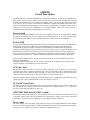
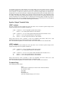
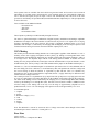
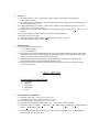
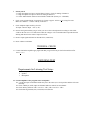
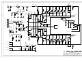
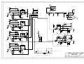
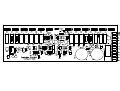
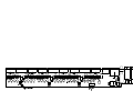
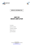
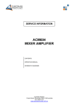
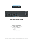
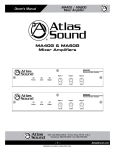
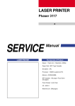
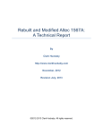
AMIS250 Series Service Manual
Product Description
Set-Up/Test Procedures
Component Lists
Full Schematics
PCB Overlays
Australian Monitor. Private Bag 149 Silverwater NSW 1811. Australia
www.australianmonitor.com.au
AMIS250
Circuit Description
The AMIS250 mixer amplifier is designed for commercial installations. It operates on [230/240 VAC,
50Hz] (240V version)/[115VAC, 60Hz] (115V version) and may be desk or rack mounted (rack mount kit
supplied). The AMIS250 delivers 250 watts into a load of 4 ohms, [70 or 100 volt line] (240V version)/ [25
or 70 volt line] (115V version). As standard, the AMIS250 is supplied self standing with rubber feet. It
features 6 microphone/line input channels as well as a host of unique features including multiple levels of
muting and 24 VDC make the AMIS250 a very flexible amplifier. [The 115V version also has a
transformer balanced, 600 ohm telephone input] (115V version).
Power Switch
This switch controls the switching of AC power to the amplifier. A blue ‘On’ LED will indicate whether
the amplifier is switched on or off. This switch will not switch DC power on or off in DC operation. In DC
operation mode, the amplifier is always on and the blue power LED will always be illuminated.
Protect LED
A feature of the AMIS250 is high temperature protection. In most applications, the internal cooling fan will
most probably never switch on. When used with demanding speaker loads or in difficult operating
environments, the fan may regularly switch on to cool the amp down and then switch off again. This
switching on and switching off is quite normal. The “Protect” function is there to protect the amplifier from
high temperature problems which would only occur if the fan stopped working or became clogged up. In
this very rare occurrence, the amplifier will shut down and the protect LED will illuminate. The amplifier
will automatically restart once it’s internal temperature has fallen below the fan switch on temperature.
The fan switch on temp is preset at 60degC by the trimmer on the power amp board R58 (10k) and the
NTC R25 (10k@25degC).
The high temperature trip point is set at the factory by trimmer R58. Turning the trim pot clockwise will
cause the amplifier to trip and mute at a lower temperature.
AC Power Inlet
The operating voltage is [230/240 VAC @ 50 Hz] (240V version)/[115 VAC @ 60Hz] (115V version). The
3 pin IEC power inlet is located on the bottom left of the rear panel and accepts a standard mains power
lead fitted with an IEC connector. Before plugging in a power lead, please check the rear panel of the
amplifier to ensure that the voltage switch is set correctly for your part of the world.
The inlet is equipped with an in-built AC fuse holder fitted with a [6.3 amp] (240V version)/[8 amp] (115V
version) fuse plus a spare within the holder. Power consumption is 550 VA.
24 Volt DC Power Inlet
The AMIS250 features optional 24VDC power to run off a battery supply if required. This is connected via
the rear terminal strip. The front panel Power Switch will not switch DC power ‘on’ or ‘off’ in DC
operation. In this mode the amplifier is always ‘on’.
[230V/240V Slide Switch] (240V version)
The operating voltage of the amplifier is user selectable between 230V and 240V via a slide switch located
on the right of the AC inlet. This switch should be set to match the AC voltage of your country. The mains
transformer is wound with a 230V winding plus a 10V winding internally connected.
Power Amp
The power amp is a push pull single supply amplifier driving a centre tapped transformer. The amplifier
has an overall gain of approximately x10 and the transformer has a turns ratio of approximately [x7] (240V
version)/[x5] (115V version). The sensitivity of the amp is approximately 2.7V.
A particularly good aspect of this amplifier is the current limiting circuit. The sensing circuit is a standard
rail load line limiting circuit but it is the drive circuit that is important. As transistors V12 & V6 (BC640)
turn on transistor V11 (BC639), it pulls bias current away from the amp through diodes D1 & D4 (BAV21)
and pulls drive away from the op amp IC1 (LM1458) through the diode/resistor pair D2/R12 (BAV21/3k3)
& D3/R23. Individually each topology acts to limit the current in the amp but it is the combination of the
two and the fine tuning of there interaction that produces the characteristic soft limiting without the harsh
crossover distortion. It is not until the amp is in hard clip does the amp produce the high freq crossover
distortion. This makes for nice sounding current limit that allows for soft distorted peaks to get through but
limits continuous excessive current while maintaining thermal stability.
Speaker Output Terminal Strip
(240V version)
The screw terminals on the left hand side of the strip allow access to the direct speaker outputs of the
amplifier. Reading from left to right the terminals are:
COM
4
Common or “-” for low impedance speaker loads (4 ohms)
Positive “+” for 4 ohm speaker loads (use with common)
COM
70
100
Common or “-” for 70v or100v speaker loads (maximum load of 40 ohms at 100v)
Positive “+” for 70v line speaker loads (use with common)
Positive “+” for 100v line speaker loads (use with common)
Please ensure that the correct “Common” is used. Low impedance and 70/100v loads can be used
simultaneously but please pay careful attention to the overall speaker load.
Note: The minimum impedance (or maximum load) at 100 volt line should be no less than 40 Ohms.
(115V version)
The screw terminals on the left hand side of the strip allow access to the direct speaker outputs of the
amplifier. Reading from left to right the terminals are:
COM
4
Common or “-” for low impedance speaker loads (4 ohms).
Positive “+” for 4 ohm speaker loads (use with common)
COM
25
70
Common or “-” for 25v or 70v speaker loads (maximum load of 20 ohms at 70v)
Positive “+” for 25v line speaker loads (use with common)
Positive “+” for 70v line speaker loads (use with common)
Please ensure that the correct “Common” is used. Low impedance and 25/70v loads can be used
simultaneously but please pay careful attention to the overall speaker load.
Note: The minimum impedance (or maximum load) at 70 volt line should be no less than 20.
Terminal Strip
The remaining terminals read as:
Spare
Tone Generator Common (use with one of the 4 tones listed below)
Pre-Announce Chime
Alert Tone
Bell Chime
Evacuation Tone
[600 Ohm Telephone Input] (115V version)
Phantom Power
This button enables or disables the 15 volts DC phantom power to all microphone inputs XLR’s. Do not
plug an unbalanced microphone in any amplifier or mixer when phantom power is switched on.
The phantom voltage is connected through 4k7 1/4W resistors. The maximum current draw available per
microphone is approximately 3mA.
Line Output
The balanced XLR line level output provides a maximum of 700mV to allow for the connection of up to 6
power amplifiers. Pin connections are: pin 1-earth; pin 2-signal (hot +); pin 3-signal (cold -).
The output is electronically balanced with an inverting op-amp and buffered with voltage follower op
amps. Neither hot nor cold output should be grounded when connecting as unbalanced.
Tape Output
Dual RCA output connectors provide a line level output with a maximum of 350mV into 10k Ohms. This
output is sourced before the master gain control so the tape output level is not influenced by the operation
of the master gain control.
Microphone Inputs
All four inputs are dual mic/line with microphone inputs being via a 3 pin XLR connector per channel. The
mic input sensitivity is 1mV @ 200 ohms. Pin connections are: pin 1-earth; pin 2-signal (hot +); pin 3signal (cold -). Phantom power of +15 volts is available on all microphone inputs. Reading from left to
right across the rear panel, the inputs are 6,5,4, 3, 2, & 1.
Line Inputs
Line inputs 1, 2, 3, 4, & 5 have an input sensitivity of 150mV @ 100K ohms. Input 6 has an input
sensitivity of 300mV @ 220K ohms making it suitable for high level inputs such as a CD player. Reading
from left to right across the rear panel, the connections are for inputs 6, 5, 4, 3, 2, & 1 respectively.
[600 Ohm Telephone Input] (115V version)
The 600 ohm transformer balanced Telephone Input is summed with input 2 through 100k ohms.
The input sensitivity is 150mV (driving the amp to full power)
Insert Point
The Insert Point is located electronically after the master volume pot and before the balancing circuit for
the power amp and line output.
The Insert Point is a 3 conductor (Tip, Ring, Sleeve) phone socket which accepts a standard stereo 6.35mm
(1/4”) jack. The connections are:
Tip
Amplifier in.
Ring
Mix Output.
Sleeve Ground
The switched contacts are used to break the signal internally.
When an external processor is used via the insert point, it only affects the power amplifier section and line
output of the AMIS60 &AMIS120. The tape output remains unprocessed.
Tone Generators
Four separate tones are available from the in-built tone generator board. All four tones can be activated
individually via a contact closure connected to the screw terminals on the rear of the amplifier. When any
tone is activated, all inputs (except for inputs 1 and 2) will automatically mute. The level of the tone
generator is controlled by the pot labeled R6 (located behind the Bass adjustment pot). This pot adjusts the
level for all 4 tones.
Tones available on the AMIS250 include:
- Evacuation Tone
- Alert Tone
- Bell Tone
- Pre-Announce Chime
Theses inputs are pulled up to 5VDC internally through 1k resistors.
The tones are generated through a combination of digital frequency modulation and analogue amplitude
modulation. The output of the microcontroller IC7 (PIC16C55A) on pin 6 is a 0-5V square wave of varying
frequency (depending on the tone selected). This signal is amplitude modulated using a VCA IC8
(M5222P). The envelope is controlled by the charging and discharging of the electrolytic capacitor C40
with the sink and sourcing of current on the microcontroller outputs pins 8, 9 & 17.
VOX Muting
This feature provides automatic muting channels 3 & 4 when signal is applied to either channels 1 or 2. It is
normally used so that a paging microphone can have priority (by muting) over background music. The
muted channels will automatically ramp back up to normal volume when the signal on channels 1 and/or 2
is no longer active. The amplifier ships with the VOX muting function enabled. To disable the VOX
muting move the jumper (labeled JP2, located just to the left and behind the level pot for channel 1) to the
middle and rear pins. (Factory setting is with VOX enabled with the jumper on the middle and front pins).
Channels 3, 4, 5 & 6 are summed through IC1A (LM1458 or equivalent) to the VCA IC4 (M5222P) which
does the muting. The VCA is held on (i.e. no attenuation) by R22 (10k) pulled to the reference voltage and
the reverse biasing of diode D2 (BAV21 or equivalent) by R20 and R21. This is to eliminate any
attenuation by the op amp IC1B (LM1458 or equivalent) and its ½ supply which may be different to the
internal reference voltage of the VCA.
The control pin of the VCA is pulled down by op amp IC1B. This op amp runs at very high gain to activate
on even very small signal. The jumper JP2 shorts out the feedback resistor thus removing the sensitivity.
The attack of the muting circuit is controlled by the charging of C13 (47uF) through R20 (100k) and the
release by the discharge if C13 through R16 (2k2). Note that VCA will mute at 250mV (-80dB) below the
reference voltage so the muting will occur only over the range of approximately (depends on VCA
production batch) 7.2V to 7.5V. The charging of the capacitor occurs from approximately 1V to 8.1V.
VCA M5222P pin out
1 – Output1
2 – Input1
3 – Reference voltage (½ Vcc)
4 – Gnd
5 – Control
6 – Input2
7 – Output2
Note: The M5222P is a current in, current out device. Voltage conversion is done through resistors. The
maximum input current is 50uA rms. Current gain is 0.5.
Fuse Sizes
(240V version)
Mains: 230 VAC 6.3 Amperes Slow Blow
DC: 10 Amperes Slow Blow
(115V version)
Mains: 230 VAC 8 Amperes Slow Blow
DC: 10 Amperes Slow Blow
TEST PROCEDURE MODEL - AMIS 250 (US)
1.
Perform physical inspection (Visual Inspection stage).
1.1 Check:
• All screws for tightness (esp. bridge rectifier and transistor bolts),
• Earth connection for good contact (XLR GND to AC earth),
• All wiring points for good contacts (soldering and crimping)
PRETESTING
PRE TESTING SETUP REQUIREMENT
a.
b.
c.
d.
e.
Oscilloscope.
Variac
Multimeter.
Load [4Ω]
Signal generator
2.
Set up amplifier for test :
2.1 Check :
• AC fuses (8A), 20mm
• DC fuses (10A), 20mm
•
2.2 Connect amplifier to :
• Variac (0 VAC),
• Signal generator (mic1, no signal),
• Resistive load ( 4Ω on 4Ω terminal ).
• Connect 24V DC supply externally for the relay on amplifier PCB. (Optional test for 24V DC
operation)
2.3 Reset controls :
• Volume controls to minimum,
• Bass/treble control to center,
• R33 & R34 (Bias adjust pots) Amplifier PCB fully anticlockwise.
3
Power up :
3.1 Turn on the power switch and adjust the variac voltage to 115VAC . Watch current meter for
excess current draw. Current should not exceed 0.5A.
3.2 Check DC power supply at the fuses, the measurement should be approximately. 40V (±1.5V)
3.3 Check DC voltage on the mixer board, the measurement should be approximately. 15V (± 0.5V).
3.4 Check 1/2 VCC on mixer board, the measurement should be 8VDC (± 0.5).
3.5 Measure the DC voltages on the IC’s of the mixer & input PCB's, Pin 8, 15V (+5%), Pin 4 0V
(+100mV),
Pin l, 8V (± 5%) but on power it should be P8 18V (± 5%) other remain same.
3.6 Put a multimeter across R47, the meter should read 0.3 mV (± 5%). Slowly adjust the preset
R 33 so that you measure 2.5mVin addition to the base reading
3.7 Repeat 3.7 for R55 adjusting preset R34.
4
AC Check:
4.1 Set signal generator to 1mV. Turn up Mic1 volume control to full. Watch for irregularities
in the output waveform.
4.2 Set output voltage to 35V using the master volume control. Check voltages across the Emitter resistors
(on the output power devices)
4.3 Voltage should be between 150mV – 200mV. Min. and Max. values should be between 33% of the
average value ( i.e. min/max = 0.5mV ).
4.4 Turn the master up to full. Check sensitivity of the microphone inputs. – MIC 1mV (+ 1mV) 32V in a
4Ω load.
4.5 Check the output level of the amplifier using each of the input channels.
4.6 Measure 25V line 70V LINE.
4.7 Check tape outputs (L and R) 300mV (+50mV) (Measure on RCA socket).
4.8 Check line outputs. Approx. (2.0V ± 25mV).
5.
Function Checks :
5.1 check the position of header links.
a. Vox muting enabled.
b. VCA Con. Disabled.
5.2 Keep signal in CH1 insert ‘INSERT-PLUG’ having external signal of different frequency the out put
should cut off and switch over to applied insert signal, check signal on inset plugs ring terminal with
respective ground should be 300mV. Remove insert plug .
5.3 Check Phantom Switch for on/off operation. Measure Phantom voltage on an XLR inputs ( the
measurement should be 14.5VDC) (Reset the phantom switch)
5.4 Switch off the set connect battery (24V) check for rated out put power (out put signal will clip up
to 2% on battery power)
FINAL TESTING
Requirements for final testing
a.
b.
c.
d.
e.
6
Load 40Ω.
Multimeter
Oscilloscope
Microphone
Variac
Check sensitivity of all channels.
6.2 Mic input (CH1-CH4) = 1mV out put =70V (± 5V)
6.3 AUX input (CH1-CH5) = 150mV out put =70V (± 5V)
6.4 AUX input (CH6) = 150mV out put = 32.5V (± 1.5V)
6.5 Check the Power bandwidth of CH 1 MIC input. – (68Hz ±5Hz – 15KHz ± 2KHz).
6.6 Check Bass control @ 100HZ = + 10dB (TOL. +1dB), MID Control + 10dB (TOL. +1dB) and treble @
10kHz = + 10dB (TOL. ± 1dB)
6.7 Check that input signal and output signal are in same phase by comparing CH 1 AUX Input and all
other Outputs ( 25V, 70v, 4Ω , 8Ω )
7
Priority check
7.2 Plug microphone into input 1 and oscillator to input 3. Check for muting of channel 3.
7.3 Plug microphone into input 2. Check for muting of channel 3.
7.4 Check ‘Mute Disable’ function. Insert Disable / Enable link (Factory set – ENABLE).
8
Check 4 tone switched inputs. Set output level of tones to approx. 14Vrms (+ 2V) using Evac tone.
Make sure channel 3 – 6 mutes with any of the tone’s.
9
Check telephone input sensitivity for CH2
Tel input =180 mV output =70V (± 5V).
10 Increase the signal such that you get 76V & you can see the overload protection coming on with a kink
visible on the sine wave if it is there then reduce the voltage to 35V out and then short output. Release the
shorting and check for the return of output waveform
11 Remove input signal and check for Hum & Noise (<20mVrms).
12 Reset volumes to minimum.
THERMAL CHECK
13 Connect load to the amplifier apply signal such that you get 42Vat out put. Set for thermal shut off at
110°C (+ 5°C)
LISTENING TEST
Requirements for Listening Test Setup :
a.
b.
c.
CD Player
Speaker
Microphone
14 Connect amplifier to the program source and speaker
14.2 Set all input pots at minimum and all tone pots to the centre (12 o’clock) position and check for turn
on thump
14.3 Check CD Player (AUX) inputs each channel and tone controls for each channel
14.4 Check Priority functions: CH 1 over CH 3 – CH 6, CH 2 over CH 3 – CH 6.
14.5 Check that all generated (alert, evacuation) tones function
1
2
3
4
5
6
8
7
R47
0.047
X3
V1
BD139
+
FAN
R60
10R
C22
47u
-
D9
1N4004
R48
C21
4u7
R61
2K2
R41
0R22
R42
0R22
R43
0R22
R44
0R22
V13
TIP36C
V14
TIP36C
V15
TIP36C
V16
TIP36C
R45
0R22
R46
0R22
D10
24V
V2
BC546
R62
10K
R63
100K
IC1A
LM1458
3
C20
4u7
2
1
R9
47k
R11
1k
4
R3
470R
V17
TIP36C
V18
TIP36C
V12
BC640
R7
1k
C27
R33 1n
100R
GND
1
FAN
2
INPUT
3
1/2VCC
4
GND
5
N/C
6
FAN ON
7
CUT OUT
8
C2
120p
C16
.33u
R64
1K
C23
680P
IC3A
LM1458
+BAT TERMINAL
C12
22P
D2
D1
BAV21 BAV21
C1
470n
TO 24VAC
POWER TR
R1
4K7
R6
10k
8V2
R57
1K
R30
10K
R10
1k
R39
10K
C9
10n
X2
D6
1N4004
D5 1N4004
R35
22K
V5
BC639
C15
47u
V11
BC639
R29
100K
R36
470k
QC10
R26
10K
4u7
LK1
R40
10K
R24
1k
C24
100P
QC11
10k
R20
C13
C6
470n
LM1458
IC3B
C4
120p
R21
1M
R58
10K
B
C18
4u7
6
R59
4K7
5
V4
BD140
D3
D4
BAV21 BAV21
R34
100R
R23
3K3
VCC
D8
4V7
R25
10K NTC
8
7
IC1B R22
LM1458 1k
C5
4u7
BP
QC/5
35VDC
QC/6
+BAT VIA DIODE
R31
10R
IC2
LM7818
R65
10R
22P
RY1
QC4
FROM FUSE F2
R19
1k
QC/2
OUTPUT TR
V10
TIP42C
V19
TIP36C
3k3
R16
V20
TIP36C
V21
TIP36C
V22
TIP36C
V23
TIP36C
V24
TIP36C
R37
2K7
R17
470R
R49
0R22
R50
0R22
R51
0R22
R52
0R22
R53
0R22
R54
0R22
R38
1k
VCC
0.047
R55
R56
0.047
GND BATTERY
C7
QC/8
15000u
GND BRIDGE RECT
QC/9
C8
15000u
C19
C10
47u
47u
A
Size
A3
Date:
File:
3
C26
470u
C11
100n
Title
2
B
V6
BC640
QC/7
1
D7
1N4004
FROM FUSE F1
QC3
R2
4K7
V8
R14 BC639
47k
QC11
35VDC FROM BRIDGE
R18
330R
C28
1n
10k
R15
35VDC TO F1 & F2
A
C
C14
47u
CT OUTPUT TR
VCC
C17
LK2
OUTPUT TR
QC/1
R8
330R
V3
BD140
X1
D
R28
2K7
V9
TIP42C
V7
BC639
BP
C3
4u7
R12
3K3
1M
R13
C
R4
3k3
C25
470u
R27
1k
D
R5
10k
35VDC
0.047
4
5
6
AMIS 250 POWER AMP
CD6306-1
C
Number
12-Feb-2003
Sheet of
C:\AMIS60-120 Manual\CD6306-1.DDB Drawn By:
7
Revision
1
8
1
RS
1
2
3
4
AG(1/2VCC)
VCC
5
6
8
7
VCC
TAPE OUT
R29
R31
100K
22K
X1/1
C25
4u7
R25
50K
D
R33
100R
C38
4u7
R7
10K
C28
R4
6K8
C26
82P
C27 .47u
1
IC2A
4 LM1458
R32
1K
AG
2
R30
22K
CH2
JP2
CH3
CH4
C1
R34
6K8
C8
4u7
R37
4K7
1M R11
R16
2k2
VCC
C13
R21
120k
AG
C33
C32
100P
R41
3K3
47u
R42
3K3
D2
R39
50K
6
5
R27
50K
C14
82p
7
IC2B
LM1458
C31
4u7
C4
4u7
100k
R28
50K
2
8 M5222
IC4 C16
1
5
3
4
AG
R5
50K
VCC
IC10B
LM358
R73
15k
R45
10K
R72
100k
X2/4 +9V
X2/5
X2/6 +19V
R52
1K
C
R71
100R
R76
100R
R40
50K
R22
10k
C20
BC546
4u7
V2
R14
3K9
X5/1
R70
AG(1/2VCC) 10R
INSERT POINT
D9
C23
4u7
C9
10u
C10
4u7
4K7
R13
C22
47u
R15
4K7
VDD
R74
4k7
R10
50K
V3
BC546
X2/3
R17
100k
4u7
R58
10K
X2/1
R48
10K
VCC
R86
47k
IC1A
1458
R3
10K
R59
10K
C5
4u7
C6
47u
R68
1K
C11
4u7
R53
1K
R67
100R
OUT
IC3A
LM1458
R46
10K
R69
1K
OUT
C30
4u7
C3
4u7
R2
R24
10K
B
R44
AG 1K
TAPE
R49
39K
8
C39
100u
GND
C21
4u7
R47
10K
100P
C34
47P
R23
10K
C
IC3B
LM1458
R35
6K8
2N7
C29
IC1B
1458
R1
10K
5N6
.03u
R12
10R
X3/1
+19VDC
C2
R20
100k
D5
D
R38
50K
VCC
R26
50K
CH6
R18
6K8
R19
50K
R50
1K
C15
33p
R8
10K
CH5
C24
.1u
R36
10K
3
CH1
C35
470u
.03u
B
R61
10K
1
2
3
HI TEMP
X4/1
D1
A
ALERT
R70
4X 1K
IC7
16C55
D6
R65 220R
D7
R64 100R
D8
28
22P
C41
27
26
4
25
5
24
6
23
7
22
8
21
9
20
10
19
BELL
11
18
EVAC
12
17
PRE AN
13
16
14
R66 1K8
15
R43
1M
XT1
R62
100k
22P
C42
R56
N.R.
C43
.47u
R9
33k
N.R.
2
IC8
8 M5222
1
4
SLOW START
HT PTC
FAN PTC
FAN
X2/2
IC10A
LM358
C37
4u7
C45
.47u
2
R75
47k
C40
22u
C36
10u
A
R60
47k
Title
Size
Number
A3
4
R51
10R
R6
10K
R57
470R
3
IC9
7805
3
Date:
File:
1
R54
10R
V1
BC546
X2/8
X2/7
5VDC
VCC
5
R63
2k2
R55
VDD
5
6
AMIS250 MIXER
CD6239-1
E
12-Feb-2003
Sheet of
C:\AMIS60-120 Manual\CD6239-12.DDB Drawn By:
7
Revision
1
1
RS
8
1
2
3
4
5
6
!
1L
D
R3
100K
C1
4u7(NP)
R1
680R
C2
4u7(NP)
R2
680R
C3
4u7(NP)
R5
22K
1R
XLR1
R29
4k7
R30
4k7
C6
150P
6
7
IC1B
LM1458
5
R6
22K
2R
R11
100K
C9
4u7(NP)
R13
680R
C10
4u7(NP)
R14
680R
R28
100R
GND
CH 1 OUT
CH 2 OUT
.1u
CH 3 OUT
!
C45
100u
C11
4u7(NP)
C8
150P
R57
100R
R16
680R
B
2
1
3
R56
100R
C12
4u7
R23
4K7
R50
10R
IC1A
LM1458
6
8
7
5
IC2B
LM1458
R18
22K
R21
680R
C23
4u7(NP)
R22
680R
C24
4u7(NP)
R26
4K7
5
C20
150P
C40
4u7
R47
680R
C39
4u7
R46
680R
C32
4u7
C27
4u7
R52
4k7
C36
150P
R51
4k7
+15V
6L
C29
C35 4u7(NP)
R35
220K
6R
C28
4u7(NP)
R34
680R
2
1
AG
3
B
6 XLR
C26
R33
4u7(NP) 680R
4
R36
22K
C31
150P
R49
4K7
2
R48
4K7
3
C21
4u7
1
IC2A
LM1458
R19
22K
TELEPHONE INPUT (US only)
A
X2
100K
R55
600:600ohm
Title
T2
Size
A3
Date:
File:
2
5 XLR
C19
150P
AG
1
C
5L
R54
220K
150P
R20
22K
4
R25
4K7
A
R45
100K
R37
22K
C34
.1u
C41
4u7
AG
PHANTOM
SW1
C16
4u7
6
R43
22K
IC3A
LM1458
4R
XLR4
D1
R42
10R
AG
R4
C22
100K 4u7(NP)
(CD)
8
7
IC3B
LM1458
VCC
VCC
C18
150P
R41
100K
4L
C42
R53
100K
5R
C37
150P
C38
4u7
R12
22K
C15
4u7(NP)
C17
150P
R24
4K7
R44
22K
VCC
R10
22K
C14
4u7(NP)
C13
4u7(NP)
LINE OUT
7 XLR
CH 5 OUT
.1u
R17
100K
R
R31
10K
R32
10K
CH 4 OUT
150P
3R
XLR3
X2/1
19VDC
C7
R40
100K
R15
680R
V1
78LS18
C43
4u7
AG
3L
D
10A SB
GND
C33
L
C
R9
22K
4
R8
4K7
F2
AG(1/2 VCC)
C4
4u7
8
X1/1
+VCC
C25
.1u
TAPE OUT
A
CH 6 OUT
R39
100K
R7
4K7
B
+45VDC
VCC
R27
10R
AG
2L
XLR2
VCC
C5
150P
+15V
C
F1
10A SB
R38
100K
8
7
3
4
5
6
AMIS 250 MIC INPUT
CD6238-1
D
Number
Revision
12-Feb-2003
Sheet of
C:\AMIS60-120 Manual\CD6238-11.DDB Drawn By:
7
RS
8
AMIS250 Power amp Component List
Designator
C1
C10
C11
C12
C13
C14
C15
C16
C17
C18
C19
C2
C20
C21
C22
C23
C24
C25
C26
C27
C28
C3
C4
C5
C6
C7
C8
C9
D1
D10
D2
D3
D4
D5
D6
D7
D8
D9
IC1A
IC1B
IC2
IC3A
IC3B
LK1
LK2
R1
R10
R11
R12
R13
R14
R15
R16
Part Type
470n
47u
100n
22P
22P
47u
47u
.33u
4u7
4u7
47u
120p
4u7
4u7
47u
680P
100P
470u
470u
1n
1n
4u7
120p
4u7
470n
15000u
15000u
10n
BAV21
24V
BAV21
BAV21
BAV21
1N4004
1N4004
1N4004
4V7
1N4004
LM1458
LM1458
LM7818
LM1458
LM1458
4K7
1k
1k
3K3
1M
47k
10k
3k3
Description
Metalised Poly 100V
Electrolytic 35V
Metalised Poly 100V
Multi Layer Ceramic 100V
Multi Layer Ceramic 100V
Electrolytic 35V
Electrolytic 35V
Metalised Poly 100V
Electrolytic 35V
Electrolytic 35V
Electrolytic 35V
Multi Layer Ceramic 100V
Electrolytic 35V
Electrolytic 35V
Electrolytic 35V
Multi Layer Ceramic 100V
Multi Layer Ceramic 100V
Electrolytic 50V
Electrolytic 50V
Multi Layer Ceramic 100V
Multi Layer Ceramic 100V
Electrolytic 35V
Multi Layer Ceramic 100V
Electrolytic 35V
Metalised Poly 100V
Electrolytic 50V
Electrolytic 50V
Metalised Poly 100V
Small Signal Diode
Zener Diode 1Watt
Small Signal Diode
Small Signal Diode
Small Signal Diode
Rectifier Diode
Rectifier Diode
Rectifier Diode
Zener Diode 1Watt
Rectifier Diode
Dual op-amp DIP 8 Pin
Dual op-amp DIP 8 Pin
Regulator T0220
Dual op-amp DIP 8 Pin
Dual op-amp DIP 8 Pin
Link
Link
Resistor, metal film 1/2 watt
Resistor, metal film 1/2 watt
Resistor, metal film 1/2 watt
Resistor, metal film 1/2 watt
Resistor, metal film 1/2 watt
Resistor, metal film 1/2 watt
Resistor, metal film 1/2 watt
Resistor, metal film 1/2 watt
Manufacturer's Code
2124262472
2121250470
2124282101
2127181220
2127181220
2121250470
2121250470
2124282331
2121230479
2121230479
2121250470
2127180121
2121230479
2121230479
2121250470
2127181681
2127181101
2121250470
2121250470
2122250017
2122250017
2121230479
2127180121
2121230479
2124262472
2121250153
2121250153
2124182100
2133400201
2136010240
2133400201
2133400201
2133400201
2133440004
2133440004
2133440004
2136010479
2133440004
2152810458
2152810458
2151370815
2152810458
2152810458
9111590472
9111590102
9111590102
9111590332
9111590105
9111590473
9111590103
9111590332
R17
R18
R19
R2
R20
R21
R22
R23
R24
R25
R26
R27
R28
R29
R3
R30
R31
R33
R34
R35
R36
R37
R38
R39
R4
R40
R41
R42
R43
R44
R45
R46
R47
R48
R49
R5
R50
R51
R52
R53
R54
R55
R56
R57
R58
R59
R6
R60
R61
R62
R63
R64
R65
R7
R8
470R
330R
1k
4K7
10k
1M
1k
3K3
1k
10K NTC
10K
1k
2K7
100K
470R
10K
10R
100R
100R
22K
470k
2K7
1k
10K
3k3
10K
0R22
0R22
0R22
0R22
0R22
0R22
0.047
0.047
0R22
10k
0R22
0R22
0R22
0R22
0R22
0.047
0.047
1K
10K
4K7
10k
10R
2K2
10K
100K
1K
10R
1k
330R
Resistor, metal film 1/2 watt
Resistor, metal film 1/2 watt
Resistor, metal film 1/2 watt
Resistor, metal film 1/2 watt
Resistor, metal film 1/2 watt
Resistor, metal film 1/2 watt
Resistor, metal film 1/2 watt
Resistor, metal film 1/2 watt
Resistor, metal film 1/2 watt
Thermistor
Resistor, metal film 1/2 watt
Resistor, metal film 1/2 watt
Resistor, metal film 1/2 watt
Resistor, metal film 1/2 watt
Resistor, metal film 1/2 watt
Resistor, metal film 1/2 watt
Metal oxide resistor 2W
Resistor, metal film 1/2 watt
Resistor, metal film 1/2 watt
Resistor, metal film 1/2 watt
Resistor, metal film 1/2 watt
Resistor, metal film 1/2 watt
Resistor, metal film 1/2 watt
Resistor, metal film 1/2 watt
Resistor, metal film 1/2 watt
Resistor, metal film 1/2 watt
Wire wound 5 watt resistor
Wire wound 5 watt resistor
Wire wound 5 watt resistor
Wire wound 5 watt resistor
Wire wound 5 watt resistor
Wire wound 5 watt resistor
Wire wound 5 watt resistor
Wire wound 5 watt resistor
Wire wound 5 watt resistor
Resistor, metal film 1/2 watt
Wire wound 5 watt resistor
Wire wound 5 watt resistor
Wire wound 5 watt resistor
Wire wound 5 watt resistor
Wire wound 5 watt resistor
Wire wound 5 watt resistor
Wire wound 5 watt resistor
Resistor, metal film 1/2 watt
Resistor, metal film 1/2 watt
Resistor, metal film 1/2 watt
Resistor, metal film 1/2 watt
Metal oxide resistor 2W
Resistor, metal film 1/2 watt
Resistor, metal film 1/2 watt
Resistor, metal film 1/2 watt
Resistor, metal film 1/2 watt
Resistor, metal film 1/2 watt
Resistor, metal film 1/2 watt
Resistor, metal film 1/2 watt
9111590471
9111590331
9111590102
9111590472
9111590103
9111590105
9111590102
9111590332
9111590102
2111911103
9111590103
9111590102
9111590272
9111590104
9111590471
9111590103
2111221100
9111590101
9111590101
9111590223
9111590474
9111590272
9111590102
9111590103
9111590332
9111590103
2111450228
2111450228
2111450228
2111450228
2111450228
2111450228
2111450177
2111450177
2111450228
9111590103
2111450228
2111450228
2111450228
2111450228
2111450228
2111450177
2111450177
9111590102
9111590103
9111590472
9111590103
2111221100
9111590222
9111590103
9111590104
9111590102
9111590100
9111590102
9111590331
R9
RY1
V1
V10
V11
V12
V13
V14
V15
V16
V17
V18
V19
V2
V20
V21
V22
V23
V24
V3
V4
V5
V6
V7
V8
V9
X1
X2
X3
47k
BD139
TIP42C
BC639
BC640
TIP36C
TIP36C
TIP36C
TIP36C
TIP36C
TIP36C
TIP36C
BC546
TIP36C
TIP36C
TIP36C
TIP36C
TIP36C
BD140
BD140
BC639
BC640
BC639
BC639
TIP42C
SIL8
SIL2
SIL2
Resistor, metal film 1/2 watt
2P2T Relay
Transistor
Transistor
Transistor
Transistor
Transistor TOP-3
Transistor TOP-3
Transistor TOP-3
Transistor TOP-3
Transistor TOP-3
Transistor TOP-3
Transistor TOP-3
Transistor
Transistor TOP-3
Transistor TOP-3
Transistor TOP-3
Transistor TOP-3
Transistor TOP-3
Transistor
Transistor
Transistor
Transistor
Transistor
Transistor
Transistor
9111590473
2523120001
2141400139
2141300042
2144200639
2144200640
2141600036
2141600036
2141600036
2141600036
2141600036
2141600036
2141600036
2144200546
2141600036
2141600036
2141600036
2141600036
2141600036
2141400140
2141400140
2144200639
2144200640
2144200639
2144200639
2141300042
AMIS250 Mixer Component list
Designator
C1
C10
C11
C13
C14
C15
C16
C2
C20
C21
C22
C23
C24
C25
C26
C27
C28
C29
C3
C30
C31
C32
C33
C34
C35
C36
C37
C38
C39
C4
C40
C41
C42
C43
C45
C5
C6
C8
C9
D1
D2
D5
D6
D7
D8
D9
IC10A
IC10B
IC1A
IC1B
IC2A
IC2B
IC3A
Part Type
5N6
4u7
4u7
47u
82p
33p
4u7
.03u
4u7
4u7
47u
4u7
.1u
4u7
.47u
82P
.03u
2N7
4u7
4u7
4u7
100P
100P
47P
470u
10u
4u7
4u7
100u
4u7
22u
22P
22P
.47u
.47u
4u7
47u
4u7
10u
LED
BAV21
BAV21
BAV21
BAV21
BAV21
BAV21
LM358
LM358
LM1458
LM1458
LM1458
LM1458
LM1458
Description
Metalised Poly 100V
Electrolytic 35V
Electrolytic 35V
Electrolytic 35V
Multi Layer Ceramic 100V
Multi Layer Ceramic 100V
Electrolytic 35V
Multi Layer Ceramic 100V
Electrolytic 35V
Electrolytic 35V
Electrolytic 35V
Electrolytic 35V
Metalised Poly 100V
Electrolytic 35V
Metalised Poly 100V
Multi Layer Ceramic 63V
Multi Layer Ceramic 100V
Multi Layer Ceramic 100V
Electrolytic 35V
Electrolytic 35V
Electrolytic 35V
Multi Layer Ceramic 100V
Multi Layer Ceramic 100V
Multi Layer Ceramic 100V
Electrolytic 35V
Electrolytic 35V
Electrolytic 35V
Electrolytic 35V
Electrolytic 35V
Electrolytic 35V
electrolytic 35V
Multi Layer Ceramic 100V
Multi Layer Ceramic 100V
Metalised Poly 63V
Metalised Poly 63V
Electrolytic 35V
Electrolytic 35V
Electrolytic 35V
Electrolytic 35V
3.0mm Red Led
Small Signal Diode
Small Signal Diode
Small Signal Diode
Small Signal Diode
Small Signal Diode
Small Signal Diode
Dual op-amp DIP 8 Pin
Dual op-amp DIP 8 Pin
Dual op-amp DIP 8 Pin
Dual op-amp DIP 8 Pin
Dual op-amp DIP 8 Pin
Dual op-amp DIP 8 Pin
Dual op-amp DIP 8 Pin
Manufacturer's Code
2124180562
2121230479
2121230479
2121250470
2127181820
2127280336
2121230479
2127280336
2121230479
2121230479
2121230479
2121230479
2128280019
2121230479
2124262472
2127181820
2127280336
2127181279
2121230479
2121230479
2121230479
2127180155
2127180155
2127181470
2121230471
2121220100
2121230479
2121230479
2121220101
2121230479
2121250220
2127181220
2127181220
2124262472
2124262472
2121230479
2121250470
2121230479
2121220100
2137200003
2133400201
2133400201
2133400201
2133400201
2133400201
2133400201
2152800358
2152800358
2152810458
2152810458
2152810458
2152810458
2152810458
IC3B
IC4
IC7
IC8
IC9
R1
R10
R11
R12
R13
R14
R15
R16
R17
R18
R19
R2
R20
R21
R22
R23
R24
R25
R26
R27
R28
R29
R3
R30
R31
R32
R33
R34
R35
R36
R37
R38
R39
R4
R40
R41
R42
R43
R44
R45
R46
R47
R48
R49
R5
R50
R51
R52
R53
R54
LM1458
M5222
16C55
M5222
7805
10K
50K
1M
10R
4K7
3K9
4K7
2k2
100k
6K8
50K
100k
100k
120k
10k
10K
10K
50K
50K
50K
50K
22K
10K
22K
100K
1K
100R
6K8
6K8
10K
4K7
50K
50K
6K8
50K
3K3
3K3
1M
1K
10K
10K
10K
10K
39K
50K
1K
10R
1K
1K
10R
Dual op-amp DIP 8 Pin
VCA DIP 8 Pin
PIC-16C55X1,TP,28PIN
VCA DIP 8 Pin
Regulator, T092
Resistor, metal film 1/2 watt
Potentiometer Linear
Resistor, metal film 1/2 watt
Resistor, metal film 1/2 watt
Resistor, metal film 1/2 watt
Resistor, metal film 1/2 watt
Resistor, metal film 1/2 watt
Resistor, metal film 1/2 watt
Resistor, metal film 1/2 watt
Resistor, metal film 1/2 watt
Potentiometer Linear
Resistor, metal film 1/2 watt
Resistor, metal film 1/2 watt
Resistor, metal film 1/2 watt
Resistor, metal film 1/2 watt
Resistor, metal film 1/2 watt
Resistor, metal film 1/2 watt
Potentiometer Linear
Potentiometer Linear
Potentiometer Linear
Potentiometer Linear
Resistor, metal film 1/2 watt
Resistor, metal film 1/2 watt
Resistor, metal film 1/2 watt
Resistor, metal film 1/2 watt
Resistor, metal film 1/2 watt
Resistor, metal film 1/2 watt
Resistor, metal film 1/2 watt
Resistor, metal film 1/2 watt
Resistor, metal film 1/2 watt
Resistor, metal film 1/2 watt
Potentiometer Linear
Potentiometer Linear
Resistor, metal film 1/2 watt
Potentiometer Linear
Resistor, metal film 1/2 watt
Resistor, metal film 1/2 watt
Resistor, metal film 1/2 watt
Resistor, metal film 1/2 watt
Resistor, metal film 1/2 watt
Resistor, metal film 1/2 watt
Resistor, metal film 1/2 watt
Resistor, metal film 1/2 watt
Resistor, metal film 1/2 watt
Potentiometer Linear
Resistor, metal film 1/2 watt
Resistor, metal film 1/2 watt
Resistor, metal film 1/2 watt
Resistor, metal film 1/2 watt
Resistor, metal film 1/2 watt
2152810458
2153850222
2159601655
2153850222
2151270805
9111590103
2021000503
9111590105
9111590100
9111590472
9111590392
9111590472
9111590222
9111590104
9111590682
2021000503
9111590104
9111590104
9111590124
9111590103
9111590103
9111590103
2021000503
2021000503
2021000503
2021000503
9111590223
9111590103
9111590223
9111590104
9111590102
9111590101
9111590682
9111590682
9111590103
9111590473
2021000503
2021000503
9111590682
2021000503
9111590332
9111590332
9111590105
9111590102
9111590103
9111590103
9111590103
9111590103
9111590393
2021000503
9111590102
9111590100
9111590102
9111590102
9111590100
R55
R56
R57
R58
R59
R6
R60
R61
R62
R63
R64
R65
R66
R67
R68
R69
R7
R70
R71
R72
R73
R74
R75
R76
R8
R86
R9
V1
V2
V3
XT1
470R
10K
10K
10K
47k
10K
100k
2k2
100R
220R
1K8
100R
1K
1K
10K
1k RN
100R
100k
15k
4k7
47k
100R
10K
47k
33k
BC546
BC546
BC546
Not Required
Not Required
Resistor, metal film 1/2 watt
Resistor, metal film 1/2 watt
Resistor, metal film 1/2 watt
Cermet Horizontal
Resistor, metal film 1/2 watt
Resistor, metal film 1/2 watt
Resistor, metal film 1/2 watt
Resistor, metal film 1/2 watt
Resistor, metal film 1/2 watt
Resistor, metal film 1/2 watt
Resistor, metal film 1/2 watt
Resistor, metal film 1/2 watt
Resistor, metal film 1/2 watt
Resistor, metal film 1/2 watt
Resistor, metal film 1/2 watt
Resistor network
Resistor, metal film 1/2 watt
Resistor, metal film 1/2 watt
Resistor, metal film 1/2 watt
Resistor, metal film 1/2 watt
Resistor, metal film 1/2 watt
Resistor, metal film 1/2 watt
Resistor, metal film 1/2 watt
Resistor, metal film 1/2 watt
Resistor, metal film 1/2 watt
Transistor
Transistor
Transistor
Resonator 4.00 MZ
9111590470
9111590103
9111590103
2002211103
9111590473
9111590103
9111590104
9111590222
9111590101
9111590221
9111590182
9111590101
9111590102
9111590102
9111590103
9111590100
9111590101
9111590104
9111590153
9111590473
9111590473
9111590101
9111590103
9111590473
9111590333
2144200546
2144200546
2144200546
2171400000
AMIS250 Input PCB component list
Designato Part Type
1 XLR
2 XLR
3 XLR
4 XLR
5 XLR
6 XLR
7 XLR
1L
RCA
1R
RCA
2L
RCA
2R
RCA
3L
RCA
3R
RCA
4L
RCA
4R
RCA
5L
RCA
5R
RCA
6L
RCA
6R
RCA
C1
4u7(NP)
C10
4u7(NP)
C11
4u7(NP)
C12
4u7
C13
4u7(NP)
C14
4u7(NP)
C15
4u7(NP)
C16
4u7
C17
150P
C18
150P
C19
150P
C2
4u7(NP)
C20
150P
C21
4u7
C22
4u7(NP)
C23
4u7(NP)
C24
4u7(NP)
C25
.1u
C26
4u7(NP)
C27
4u7
C28
4u7(NP)
C29
4u7(NP)
C3
4u7(NP)
C31
150P
C32
4u7
C33
.1u
C34
.1u
C35
150P
C36
150P
C37
150P
C38
4u7
C39
4u7
C4
4u7
C40
4u7
Description
XLR Connector female
XLR Connector female
XLR Connector female
XLR Connector female
XLR Connector female
XLR Connector female
XLR Connector male
RCA Connector Female
RCA Connector Female
RCA Connector Female
RCA Connector Female
RCA Connector Female
RCA Connector Female
RCA Connector Female
RCA Connector Female
RCA Connector Female
RCA Connector Female
RCA Connector Female
RCA Connector Female
Non Polar Electrolytic 50V
Non Polar Electrolytic 50V
Non Polar Electrolytic 50V
Electrolytic 35V
Non Polar Electrolytic 50V
Non Polar Electrolytic 50V
Non Polar Electrolytic 50V
Electrolytic 35V
Multi Layer Ceramic 100v
Multi Layer Ceramic 100v
Multi Layer Ceramic 100v
Non Polar Electrolytic 50V
Multi Layer Ceramic 100v
Electrolytic 35V
Non Polar Electrolytic 50V
Non Polar Electrolytic 50V
Non Polar Electrolytic 50V
Metalised Poly 100V
Non Polar Electrolytic 50V
Electrolytic 35V
Non Polar Electrolytic 50V
Non Polar Electrolytic 50V
Non Polar Electrolytic 50V
Multi Layer Ceramic 100v
Electrolytic 35V
Metalised Poly 100V
Metalised Poly 100V
Multi Layer Ceramic 100v
Multi Layer Ceramic 100v
Multi Layer Ceramic 100v
Electrolytic 35V
Electrolytic 35V
Electrolytic 35V
Electrolytic 35V
Manufacture's Code
2587210266
2587210266
2587210266
2587210266
2587210266
2587210266
2587110227
2581420102
2581420102
2581420102
2581420102
2581420102
2581420102
2581420102
2581420102
2581420102
2581420102
2581420102
2581420102
2120250479
2120250479
2120250479
2121230479
2120250479
2120250479
2120250479
2121230479
2127180155
2127180155
2127180155
2120250479
2127180155
2121230479
2120250479
2120250479
2120250479
2124182100
2120250479
2121230479
2120250479
2120250479
2120250479
2127180155
2121230479
2124182100
2124182100
2127180155
2127180155
2127180155
2121230479
2121230479
2121230479
2121230479
C41
C42
C43
C45
C5
C6
C7
C8
C9
D1
F1
F2
IC1A
IC1B
IC2A
IC2B
IC3A
IC3B
L
R
R1
R10
R11
R12
R13
R14
R15
R16
R17
R18
R19
R2
R20
R21
R22
R23
R24
R25
R26
R27
R28
R29
R3
R30
R31
R32
R33
R34
R35
R36
R37
R38
R39
R4
R40
R41
4u7
.1u
4u7
100u
150P
150P
150P
150P
4u7(NP)
Electrolytic 35V
Metalised Poly 100V
Electrolytic 35V
Electrolytic 25V
Multi Layer Ceramic 100v
Multi Layer Ceramic 100v
Multi Layer Ceramic 100v
Multi Layer Ceramic 100v
Non Polar Electrolytic 50V
2121230479
2124182100
2121230479
2121220101
2127180155
2127180155
2127180155
2127180155
2120250479
10A SB
10A SB
LM1458
LM1458
LM1458
LM1458
LM1458
LM1458
RCA
RCA
680R
22K
100K
22K
680R
680R
680R
680R
100K
22K
22K
680R
22K
680R
680R
4K7
4K7
4K7
4K7
10R
100R
4k7
100K
4k7
10K
10K
680R
680R
220K
22K
22K
100K
100K
100K
100K
100K
Dual op-amp DIP 8 Pin
Dual op-amp DIP 8 Pin
Dual op-amp DIP 8 Pin
Dual op-amp DIP 8 Pin
Dual op-amp DIP 8 Pin
Dual op-amp DIP 8 Pin
RCA Connector Female
RCA Connector Female
Resistor, metal film 1/2 watt
Resistor, metal film 1/2 watt
Resistor, metal film 1/2 watt
Resistor, metal film 1/2 watt
Resistor, metal film 1/2 watt
Resistor, metal film 1/2 watt
Resistor, metal film 1/2 watt
Resistor, metal film 1/2 watt
Resistor, metal film 1/2 watt
Resistor, metal film 1/2 watt
Resistor, metal film 1/2 watt
Resistor, metal film 1/2 watt
Resistor, metal film 1/2 watt
Resistor, metal film 1/2 watt
Resistor, metal film 1/2 watt
Resistor, metal film 1/2 watt
Resistor, metal film 1/2 watt
Resistor, metal film 1/2 watt
Resistor, metal film 1/2 watt
Resistor, metal film 1/2 watt
Resistor, metal film 1/2 watt
Resistor, metal film 1/2 watt
Resistor, metal film 1/2 watt
Resistor, metal film 1/2 watt
Resistor, metal film 1/2 watt
Resistor, metal film 1/2 watt
Resistor, metal film 1/2 watt
Resistor, metal film 1/2 watt
Resistor, metal film 1/2 watt
Resistor, metal film 1/2 watt
Resistor, metal film 1/2 watt
Resistor, metal film 1/2 watt
Resistor, metal film 1/2 watt
Resistor, metal film 1/2 watt
Resistor, metal film 1/2 watt
Resistor, metal film 1/2 watt
2152810458
2152810458
2152810458
2152810458
2152810458
2152810458
2581420102
2581420102
9111590681
9111590223
9111590104
9111590223
9111590681
9111590681
9111590681
9111590681
9111590104
9111590223
9111590223
9111590681
9111590223
9111590681
9111590681
9111590472
9111590472
9111590472
9111590472
9111590100
9111590101
9111590472
9111590474
9111590472
9111590103
9111590103
9111590681
9111590681
9111590224
9111590223
9111590223
9111590104
9111590104
9111590104
9111590104
9111590104
R42
R43
R44
R45
R46
R47
R48
R49
R5
R50
R51
R52
R53
R54
R55
R56
R57
R6
R7
R8
R9
T2
V1
10R
22K
22K
100K
680R
680R
4K7
4K7
22K
10R
4k7
4k7
100K
220K
100K
100R
100R
22K
4K7
4K7
22K
600:600Ω
78LS18
Resistor, metal film 1/2 watt
Resistor, metal film 1/2 watt
Resistor, metal film 1/2 watt
Resistor, metal film 1/2 watt
Resistor, metal film 1/2 watt
Resistor, metal film 1/2 watt
Resistor, metal film 1/2 watt
Resistor, metal film 1/2 watt
Resistor, metal film 1/2 watt
Resistor, metal film 1/2 watt
Resistor, metal film 1/2 watt
Resistor, metal film 1/2 watt
Resistor, metal film 1/2 watt
Resistor, metal film 1/2 watt
Resistor, metal film 1/2 watt
Resistor, metal film 1/2 watt
Resistor, metal film 1/2 watt
Resistor, metal film 1/2 watt
Resistor, metal film 1/2 watt
Resistor, metal film 1/2 watt
Resistor, metal film 1/2 watt
Isolation Transformer US only
Regulator 18V
9111590100
9111590223
9111590223
9111590104
9111590681
9111590681
9111590472
9111590472
9111590223
9111590100
9111590472
9111590472
9111590104
9111590224
9111590104
9111590101
9111590101
9111590223
9111590472
9111590472
9111590223
2651280253
2151370818
AMIS 250 Major Components price list
Part
Description
Manufacturer code
PCB's
Mixer
Input
Output
LED
Mixer PCB
Input PCB assy
Output PCB assy
Display PCB
S5728MAMIS250S16
S5728MAMIS250S17
S5728MAMIS250S18
S5728MAMIS250S21
Transformers
230/240VAC
120VAC
Output
FUSE 12 Amp
Mains 230/240V
Mains 120V
Output
DC rail fuse
in house AUD$
$75.54
$26.26
$114.43
$5.13
2651983262
$56.76
2651983264
2541201125
$42.66
$0.33
Semiconductors
TIP36C
TIP42C
BC639
BC640
BD140
BD139
LM1458
LM833N
LM358
LM78L05
LM7815
LM7818
PIC16C54-XTP
LM5222
10k Thermistor
PNP TO3P transistor
PNP TO220 transistor
NPN TO92
PNP TO92
PNP TO92
NPN TO92
IC Dual Op amp
IC Dual Op amp
IC Dual Op amp
IC Regulator
IC Regulator
IC Regulator
Program IC
IC VCA
2141600036
2141300042
2144200639
2144200640
2141400140
2141400139
2152801048
2157800833
2152800358
2151270805
2151370815
2151370818
2159601654
2153850222
2111911103
TIP36C
TIP42C
S7007
S7008
channel & master
Round rocker switch
2021000503
2511213112
$0.56
$1.39
S600000151
S600000149
S600000137
S600000152
$3.61
$14.45
$4.35
$16.15
S7009
LM1458
LM833
LM358
LM7805
LM7815
LM7818
120PIC
$3.59
$2.00
$0.16
$0.16
$0.22
$0.22
$0.26
$1.05
$1.05
$0.17
$0.52
$0.52
$4.17
$0.57
$0.29
Switches & Pots
Volume Pot
Power switch
Hardware
Front Panel
Lid
Rack ears
Chassis
Barrier Strip 6
Phono connector
XLRF
XLMR
Screw + washer
Screw
Knob
Acrylic cover for
6 way terminal
6 way barrier connector
1/4" socket
Black screw w/star
Black screw wo/star
volume & master
2583528306
2582110645
2587210266
2587110227
2316420308
2316421306
9346110015
9347560006
$2.51
$0.86
$1.34
$1.08
$0.04
$0.04
$0.12
$0.31