1
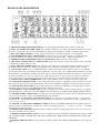
OPERATING / SERVICE MANUAL
CM 86
QUICK START
Think of this like a fortune cookie: you have to read the saying before you eat it. But unlike a fortune cookie we don’t
want you to break your CM 86 before getting the message. So here’s your fortune:
Rane adheres to the AES/ANSI/IEC standards of pin 2 positive, pin 3 negative and pin 1 ground. Choose between either
the 3-pin (XLR-type) or the terminal strip MIC IN. Use only ONE; they are in parallel and do NOT sum. The LINE IN
(unbalanced 1/4") is grounded when not used. This allows the MIC/LINE switch to act as an input MUTE switch whenever the LINE IN jack is not used. Likewise, if it is used then the MIC/LINE switch acts like a true source selector. Set
the rear-mounted MIC GAIN control as necessary for your mic. Use the OL indicator as an adjustment aid: increase gain
until this LED occasionally lights. Optimum noise performance results from taking as much gain as possible. (The OL indicator on the front panel parallels the one on the rear.) Select PHANTOM POWER as needed for each channel independently. When setting channel equalization, use the IN/OUT switch to compare equalized with unequalized material.
When using the AUX A/B level controls, remember to set the desired take-off location using the PRE/POST switches.
PRE takes this signal before the Channel LEVEL controls, allowing independent operation of both. POST takes this signal
after the Channel LEVEL controls, allowing the LEVEL controls to turn the Aux levels up/down simultaneously. Set the
OUTPUT SELECT to assign each input channel to the desired output. Choose between “A” only, “B” only or “AB” both.
Note that choosing only one, say “A,” routes this input to both MASTER 1A and MASTER 2A outputs, but nothing goes
to either B output.
When setting input AUX A/B and LEVEL A/B controls, keep an eye on the appropriate PRE-OUTPUT OVERLOAD indicators. They monitor overloading of the critical summing stages. Use the METER & HEADPHONE ASSIGN switch to
select the desired output for metering and monitoring. The HEADPHONE connects to the same point as the OUTPUT METERS — what you see is what you hear.
Read the Rane FLEX USERS GUIDE for details about the Flex DIN connectors. Expansion and augmentation of the CM
86 is easily done using this handy bus. TAPE OUT is taken after the MASTER INSERT LOOPS and before the MASTER
1 & 2 OUT LEVEL controls. The MASTER INSERT LOOPS do not affect the AUX A & B outputs. All four MASTER
OUTS are driven by high-current cross-coupled line drivers which will drive lines 1000 feet (305 meters) using Belden
8451 or equal wire.
Miscellaneous: The CM 86 does NOT invert signals. Use the LIFT (ground lift) switch to help eliminate stubborn hum
problems. NEVER CONNECT ANYTHING EXCEPT AN APPROVED RANE RS 2 (the big one) POWER SUPPLY
TO THE RED JACK ON THE REAR OF THE UNIT.
Good fortune and great wealth are coming your way.
SYSTEM CONNECTION
When first connecting the CM 86, LEAVE THE POWER SUPPLY FOR LAST. This gives you a chance to make mistakes and correct them without damaging your fragile speakers, ears and nerves.
INPUTS. Each input channel has two MIC IN connectors. The 3-pin (XLR-type) connector and the terminal strip are wired
in parallel and either one works equally well; however, they do NOT sum. USE ONLY ONE. Choose strictly from a required hardware point-of-view, there is no performance trade-off. Wiring convention conforms to the AES/ANSI/IEC standard of pin 2 positive, pin 3 negative and pin 1 ground, with the shell being tied to chassis. Microphones requiring Phantom
Powering must tie pin 1 to the shield, otherwise the Phantom Power circuit is not completed. The LINE IN is an unbalanced
1/4" jack, and may be used in conjunction with the MIC IN. The MIC/LINE switch then operates as a selector switch. When
(continues on last page...)
FRONT PANEL DESCRIPTION
1. INPUT SOURCE SELECTOR. This slide switch selects between MIC or LINE inputs. Both inputs may be used; in
which case this switch acts as a true source selector. If the LINE input is not used then it is internally grounded and this
switch acts like a Mic Mute when moved to the LINE position.
2. INPUT OVERLOAD INDICATOR. This red LED parallels an identical one in the rear and monitors all critical input
nodes. It lights whenever these levels exceed 4dB below clipping. Occasional flickering is normal; however., it should not be
allowed to light steadily.
3. INPUT EQUALIZATION CONTROLS. A two-band shelving LOW (bass) and HIGH (treble) tone control circuit.
These controls adjust the frequency contour of both MIC and LINE inputs. The EQ is located before the INSERT LOOP.
4. EQ IN/OUT ENGAGE SWITCH. This slide switch controls the EQ circuits. Useful for comparing equalized (IN) with
unequalized (OUT) signals, or for guaranteeing flat frequency response (OUT).
5. PRE/POST AUX-ASSIGN SWITCHES. These slide switches allow choosing the AUX take-off points. Selecting PRE
places the AUX Level before the Channel LEVEL controls, thus allowing independent operation between the two. Selecting
POST takes the AUX Level after the Channel LEVEL controls, thereby allowing the LEVEL controls to affect all outputs.
6. AUX CONTROLS. Separate controls for mixing the input channel into the AUX A and AUX B Output (Send) signals.
7. OUTPUT SELECT SWITCH. A three-position slide switch that selects routing of this input channel. Choosing either
“A” or “B” puts all of this signal into only the A or B outputs. Choosing “AB” puts this signal equally into both.
8. CHANNEL LEVEL A/B CONTROLS (Input Faders). Concentric controls used to set the amount of signal mixed into
the MASTER A and B outputs.
9. TAPE/CD MIX CONTROLS. Three rotary controls that set the amount of the Tape, Tuner, or CD input signals mixed
in with the AUX A, AUX B or MASTER outputs.
IO. AUX IN/RETURN LEVEL CONTROL. Concentric knobs that control the amount of AUX signal coming into the
AUX OUT/IN jacks (on the ring). Often the return path from an effects box in the AUX OUT/IN LOOP; or alternatively, it
may control a separate AUX input.
11. AUX OUT/SEND LEVEL CONTROL. Concentric knobs that control the amount of AUX signal coming out of the
AUX OUT/IN jacks (on the tip). Often the send path for an effect box in the AUX OUT/IN LOOP; or alternatively, it is the
AUX output level.
12. PRE-OUTPUT OVERLOADS. LED indicators monitoring the four critical summing stages (Master A/B and Aux
A/B). They light 4dB before actual clipping. Occasional blinking is okay, but do not allow them to light steady.
13. MASTER 1 OUT STEREO/MONO SWITCH. A slide switch used to mono the MASTER 1A & 1B outputs.
14. MASTER 1 OUTPUT LEVEL CONTROLS. Concentric controls used to set the desired output level.
15. MASTER 2 OUT STEREO/MONO SWITCH. A slide switch used to mono the MASTER 2A & 2B outputs.
16. MASTER 2 OUTPUT LEVEL CONTROLS. Concentric controls used to set the desired output level.
17. METER & HEADPHONE ASSIGN SWITCH. A three-position slide switch used to choose between MASTER
1A/1B, MASTER 2A/2B or AUX A/B outputs for monitoring by the OUTPUT METERS and HEADPHONE circuits.
18. POWER INDICATOR. A yellow LED that lights whenever proper power is applied to the CM 86.
19. HEADPHONE JACK. A standard 1/4" jack for stereo headphones. This allows headphone monitoring of whatever output is selected. Standard wiring convention is followed, i.e., Tip=Left ear= Channel A, and Ring=Right ear=Channel B.
20. HEADPHONE LEVEL CONTROL. Used to set the desired headphones listening level.
21. OUTPUT METER. A two-channel 6-segment peak responding LED meter accurately calibrated in dBu units.
REAR PANEL DESCRIPTION
1. PHANTOM POWER SELECTOR SWITCH. Turns the microphone Phantom Power voltage ON and OFF.
2. INPUT OL (OVERLOAD) INDICATOR. This red LED is identical to one on the front panel and monitors all critical
input nodes. It lights when these levels exceed 4dB below clipping. Some flickering is normal; it should not light steadily.
3. MIC GAIN TRIM CONTROL. A rotary control used to set the correct gain required by your microphone.
4. 3-PIN MICROPHONE INPUT CONNECTOR. Pin 2 is positive, pin 3 is negative and pin 1 is signal and shield
ground. This connector is in parallel with the terminal strip below. USE ONLY ONE — THEY DO NOT SUM.
5. TERMINAL STRIP MICROPHONE INPUT CONNECTOR. Parallels the 3-pin connector above.
6. LINE INPUT CONNECTOR, 1/4" UNBALANCED (mono) input connector. Use for any line-level source. This input
is automatically grounded when not used.
7. INPUT CHANNEL INSERT LOOP. This jack allows any outboard unit to be patched in-series with the input signal.
LOCATED POST-EQ. Wired per standard tip=send/rimg=return convention. Automatically bypassed when not used.
8. AUX OUT/IN JACKS. A pair of UNBALANCED 1/4" TRS jacks used for either AUX OUT alone, or as a Send/Receive (Out/In) effects loop for recording and other applications. For AUX OUT, use a standard MONO unbalanced 1/4" plug
(the IN function is automatically grounded). For effects loop use, this jack follows the standard tip=send (out) / ring=receive
(in) wiring convention. Very clever (or desperate) users make use of this jack as a direct input to the Master summing networks. To do this, use a 1/4" TRS plug wired with the input signal going to the RING and leave the TIP open (unused).
9. TAPE/CD INPUT MONO PUSHBUTTON. Used to mono whatever source is connected to the RCA input jacks.
10. TAPE/CD RCA INPUTS JACKS. A pair of RCA jacks used to connect a Tape player, Tuner, CD player, or any linelevel source requiring this type of jack. Sums directly into the Aux and Master mixing buses via the Level controls on front.
11. TAPE OUTPUT RCA JACKS. A pair of RCA jacks used to connect a Tape Recorder. This output signal is located
AFTER the Master Insert Loops and BEFORE the Master Output Level controls.
12. FLEX BUS IN & OUT CONNECTORS. A pair of 7-pin DIN jacks used to expand to another CM 86, or to augment
input/output features by adding any of the Flex Modules using the Flex Bus. See the Rane FLEX USERS GUIDE for details.
13. MASTER INSERT LOOP JACKS. 1/4" TRS jacks wired tip=send/ring=return used to add any outboard effects unit
in series with all the Master Outputs. Located BEFORE the Tape Out jacks.
14. MASTER 2 A & B OUTPUT 3-PIN CONNECTORS. Pin 2 is positive, pin 3 is negative and pin 1 is signal ground.
Do NOT use pin 1 for true balanced interconnection; tie shield at one end ONLY. Unbalanced use requires grounding of pin
3, i.e., tie pin 3 to pin 1.
15. MASTER 1 A & B OUTPUT TERMINAL STRIP. Do NOT use COMMON GROUND for true balanced interconnection; tie shield at one end ONLY. Unbalanced use requires grounding of negative (“–”) output, i.e., tie the “–” and COMMON GROUND terminals together.
16. GROUND LIFT SWITCH. Provides the ability to separate chassis and signal grounds. Do not move this switch with
your power amplifiers turned on and up.
17. REMOTE POWER SUPPLY INPUT. The unit is supplied with the large Model RS 2 Remote Power Supply. NEVER
USE A POWER SUPPLY OTHER THAN THE ONE SUPPLIED OR A REPLACEMENT APPROVED BY RANE CORPORATION.
18. CHASSIS GROUND POINT. Used for chassis grounding purposes. See CHASSIS GROUNDING on the last page for
details.
(System Connection - continued from first page...)
the LINE IN is not used, it automatically grounds internally. This allows the MIC/LINE switch now to act like a
mic mute switch since selecting LINE sees a grounded
input.
The input channel INSERT LOOP allows any external
processor to be tied in series with the input source before
the MASTER and AUX Level controls. It is wired per the
tip = send/ring = return convention.
A pair of RCA input jacks allow hook-up of a Tape
Player, Tuner or CD Player. Use the MONO switch to
combine the stereo inputs as required.
OUTPUTS. High-current cross-coupled amplifers drive
each of the four main outputs. The MASTER 1 OUTS
leave through terminal strips while the MASTER 2 OUTS
exit through 3-pin connectors wired per above. Use standard balanced wiring procedures of NOT connecting
ground between units, and grounding the shield only at
ONE end. If for some unforgiveable reason you run unbalanced, then you MUST short pin 3, or the “–” terminal to
pin 1 or ground. Cross-coupled output stages demand
GROUNDING of the unused output when operated unbalanced. The AUX OUT/IN jacks serve two functions: 1) As
Auxiliary Outputs use normal mono (l-wire) unbalanced
1/4" cable and connectors; 2) For effect box use, use stereo
(2-wire) 1/4" TRS interconnecting cable and connectors
wired per the standard insert loop convention of
tip= send/ring= return. Since the AUX OUTS are unbalanced, they CANNOT be used to drive long (greater than
100 feet or 30.5 meters) lines. The unbalanced TAPE OUT
RCA jacks should be treated similarly, i.e., restrict their
IMPORTANT NOTE
CHASSIS GROUNDING
The CM 86 is supplied with a rear mounted LIFT
(ground-lift) switch. The unit is shipped with this switch
in the “grounded” position, tying circuit ground to chassis ground. If after hooking up your system it exhibits
excessive hum or buzzing, there is an incompatibility in
the grounding configuration. Your unholy task is to discover how this particular system wants to be grounded.
Here are some things to try:
1. Try combinations of lifting grounds on units supplied with ground lift switches or links.
2. If your equipment is in a rack, verify that all chassis
are tied to a good earth ground, either through the line
cord grounding pins or through the rack screws via another grounded chassis.
3. Units with outboard power supplies do NOT ground
their chassis through the line cord. Make sure that these
units are grounded either to another chassis which is
earth grounded, or directly to the grounding screw on an
AC outlet cover by means of a wire connected to the
CHASSIS GROUNDING SCREW.
Please refer to Rane Note 110 (supplied with your unit
and available on request at no charge if you lost your
first one) for further information on system grounding.
OPERATING INSTRUCTIONS
SETTING MIC GAIN CONTROL. Use the exact microphone for each input and approximate expected normal program levels and content. Observe the OL (Overload)
indicator (above and to the right) as you increase the MIC
GAIN control. The proper setting is when the OL light ocassionally flickers with program material, but does not
come on steady for long periods of time. The best signal-tonoise performance results from taking as much gain as possible at this stage. The OL indicator located at the top front
of each input channel is a duplicate of the one in the rear.
If an input sounds distorted, check these lights and turn
down the MIC GAIN as necessary.
USING THE MIC/LINE SWITCH. Choosing between
the MIC and LINE inputs is done with this slide switch.
The LINE input is a bonafide separate input (not a pad inserted in the MIC input), which allows both inputs to be active and selected at any time. Additionally, the LINE input
is automatically grounded when NOT in use, which lets
this switch then act as a MIC MUTE.
FLEX BUS. The Flex Bus allows you to expand the CM
86 using either another CM 86 or any of the Flex bus modules. The bus carries four signal lines (Master A & B and
Aux A & B) and two spare. The signal lines come into the
CM 86 via the FLEX BUS IN connector, sum with all
local inputs and exit via the FLEX BUS OUT connector.
This mixing is done before the Master Insert Loops. Signal
comes straight in, mixes into the four summing buses and
goes straight out. The two spare lines simply tie the bus
connectors together. See the FLEX USERS GUIDE for additional details.
FOUR INDEPENDENT OUTPUT MIXES. The CM 86
allows you to create up to four independent output mixes:
MASTER A, MASTER B, AUX A and AUX B. For true
independence of the AUX mixes, remember to position the
assign switches to the PRE position, otherwise changing
input LEVEL controls also affects AUX levels.
Observe that MASTER OUT 1 and MASTER OUT 2 are
the same mix, but may be set for different levels.
Copyright 1992, Rane Corporation 10802 47th Ave. W., Mukilteo, WA 98275-5098 (425)355-6000
All features & specifications subject to change without notice. 520-230 892