1
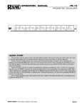
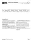
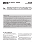
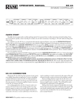
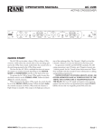
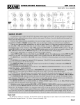
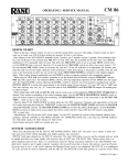
OPERATING / SERVICE MANUAL
DMS 22
DUAL MICROPHONE STAGE
QUICK START
Even if you don’t like to read manuals read this part. We’ll make it quick and painless. We promise. Damage to your
equipment, though unlikely, is a possibility if the DMS 22 is used improperly.
Turn both INPUT GAIN controls, both OUTPUT LEVEL controls and the STEREO OUTPUT LEVEL control
fully counterclockwise (CCW). Connect your mic(s) to the INPUT jack(s) located on the rear of the unit. If your mic(s)
require phantom power press the 48V PHANTOM POWER switch(es) on the front panel. Set the EQ switch to OUT.
Decision time: will you use the DMS 22 to mix your mic(s) to a two channel feed? If the answer is yes, connect the
STEREO OUTPUT(s) (XLR) located on the rear of the unit to a line level input on your mixer. If the answer is no,
connect the CHANNEL OUTPUT(s) (¼" TRS) to a line level input on your mixer. If you are using the STEREO
OUTPUT(s) of the DMS 22 then engage the PAN switch(es) and set the PAN controls where you want them. Plug the
included power supply (see note below) into the DMS 22. The yellow POWER LED should light and if Phantom Power is
being used the red PHANTOM POWER LED should be lit. Now whisper, yell or scream into your mic the loudest sound
you expect to deliver during your session or performance. While doing this adjust the INPUT GAIN control so that the
loudest whisper, yell or scream will just barely illuminate the OL LED. With that done you can adjust both OUTPUT
LEVEL controls and the STEREO OUTPUT LEVEL until the desired input level is reached.
Never connect anything except an approved Rane power supply ot the thing that looks like a red telephone jack on
the rear of the DMS 22. This is an AC input and requires special attention if you do not have an operational power supply
exactly like the one originally packed with your unit. See the full explanation of the power supply requirements elsewhere
in this manual.
DMS 22 CONNECTION
When connecting the DMS 22 to other components in
your system leave the power supply for last. This will give
you a chance to make mistakes and correct them before any
damage is done to your fragile speakers, ears and nerves.
INPUTS on the DMS 22 are balanced. This means that
standard XLR connectors on the ends of any good quality
cable will work well with the DMS 22 and microphones of
your choosing. As with all Rane products, pin 2 is used for
“hot” or “+” polarity, pin 3 is “return” or “–” and pin 1 is
chassis ground. If you are not using Phantom Power you may
use either pin 1 or case for shield ground on the DMS 22
Input. However, if you are using Phantom Power, pin 1 must
WEAR PARTS: This product contains no wear parts.
be shield ground to provide a complete electrical circuit. (See
RaneNote 110, “Sound System Interconnection” included in
this manual for further information on this subject).
OUTPUTS on the DMS 22 are all fully balanced. On
these Outputs pin 2 or tip is “hot” or “+”, pin 3 or ring is
“return” or “–” and pin 1 or sleeve is chassis ground. If an
unbalanced Output is desired do not short pin 3 or ring to
ground. Instead use a XLR connector or ¼" TRS (depending
on the output you are using) and do not connect pin 1 or the
sleeve of the ¼" TRS connector. Again, see RaneNote 110 for
more details.
Manual-1
FRONT PANEL DESCRIPTION
햲ÿ POWER indicator: illuminates yellow any time an approved Rane AC remote supply such as an RS 1 (included) or RAP
10 is connected to the unit and is active.
햳ÿ 48V PHANTOM POWER switch & indicator: In the in position, 48 volts DC Phantom Power is applied to pins 2 and 3
of the INPUT connector. When Phantom Power is on the LED will illuminate.
햴ÿ POLARITY switch: allows the user to change the Output polarity in respect to the Input polarity. It affects all Outputs. In
the NORM position, polarity is preserved throughout the unit. In the INVERT position, signal polarity is reversed from the
Input to the Output.
햵ÿ OL LED indicator: illuminates red any time signal is within 4 dB of clipping. Two key locations are monitored.
햶ÿINPUT GAIN control: increases Input GAIN as it is rotated clockwise. Its range is 15 dB of gain at full CCW rotation to
60 dB at full CW rotation.
햷ÿ OUTPUT LEVEL control: is an attenuation-type control that adds no gain, but can reduce the amount of output signal. At
full CCW no signal will be present at any DMS 22 Output, and at full CW no attenuation will be applied to the signal,
allowing full signal to CHANNEL OUTPUTS and to the STEREO OUTPUT LEVEL controls.
햸ÿ LOW EQ level control: determines the amount of boost or cut applied to the DMS 22’s Accelerated Slope (TM) low
frequency shelving equalizer. The center detent provides a ground for the filter, thus bypassing it. Rotating this knob CW
increases signal gain below the frequency set by the Low Frequency Turnover Switch to a maximum of +12 dB with a
shelving characteristic; CCW from center decreases the gain to a minimum of -15 dB.
햹ÿ LOW frequency turnover switch: determines the mid band filter location at either 50 Hz or 100 Hz. For full boost/cut
amounts, this frequency is where the gain change equals approximately 9 dB.
햺ÿ MIDRANGE EQ level control: As above, CW rotation increases gain, CCW rotation decreases gain. In center detent the
control is grounded and effectively removed from the circuit. For the MID FREQUENCY EQ we have a bandpass type filter
as opposed to a shelving type filter. The range is -15 dB to +12 dB.
햻ÿ MIDRANGE OCTAVE bandwidth selector: allows the user to select 1/3, 1 or 2 octave coverage for the midrange filter.
햽ÿ MIDRANGE frequency control: determines the center frequency of the midrange filter with a range of 95 Hz to 4 kHz.
햾ÿ HIGH EQ level control: determines the amount of boost or cut applied to the patented Accelerated Slope (TM) high
frequency shelving equalizer. In center detent the control is grounded and effectively removed from the circuit. CW rotation
increases the gain of the mixer above the frequency set by the High Frequency Turnover Switch to a maximum of +12 dB in
a shelving fashion; CCW from center decreases the gain to a minimum of -15 dB.
햿ÿ HIGH frequency turnover switch: selects the mid-band location of the High filter at either 7 kHz or 12 kHz. For full
boost/cut amounts, this frequency is where the gain change equals approximately 6 dB.
헀ÿ EQ engage switch: In the IN position the EQ controls actually work. In the OUT position all EQ controls simply add to the
stylish looks of the unit and do nothing.
헁ÿ PAN control: In the center position, this control sends an equal amount of signal to both the LEFT and RIGHT STEREO
OUTS with the PAN pushbutton IN. As you rotate this control CW more of the signal is sent to the RIGHT STEREO OUT
and less to the LEFT STEREO OUT. Conversely if you rotate this control CCW more of the signal is sent to the LEFT and
less to the RIGHT. This control does not affect the individual CHANNEL OUTPUTS.
헂ÿ PAN engage switch: In the IN position, the PAN control operates as described above. In the OUT position it is believed
that all the Planets are held in their correct Solar orbit, the PAN control does not function, and that Channel does not send a
signal to the STEREO OUTPUTS.
헃ÿ STEREO OUTPUT LEVEL control: is an attenuation-type control which adds no gain to the Output signal but can reduce
the amount of signal available at (only) the STEREO OUTPUTS. At full CCW no signal will be present at the STEREO
OUTPUTS. At full CW no attenuation will be applied, delivering full signal to the STEREO OUTPUTS. Note: this controls
does nothing unless one or more of the PAN IN/OUT switches are in the IN position. Consequently the Planets of our Solar
system may fall out of orbit.
Manual-2
REAR PANEL DESCRIPTION
햲ÿ XLR mic INPUT connector: is a fully balanced mic Input. Pin 2 is positive, pin 3 is negative and pin 1 is chassis ground.
햳ÿ LOW FREQUENCY cut off FILTER: allows you to roll off the low frequency end of the signal at three different preset
locations. In the 15 Hz position, there is essentially no roll off of the low end within the normal audio frequency range. 50
Hz and 100 Hz are available to help remove mic bumps and rumble that might otherwise ruin a good session or performance. These frequencies are the -3 dB points.
햴ÿ Individual CHANNEL OUTPUT: This is a fully balanced ¼" TRS connector. This Output is not mixed between Channels
so CHANNEL 1 signal can never be present on the INDIVIDUAL CHANNEL 2 OUTPUT and vice-versa. The Output is
considered to be line level.
햵ÿ XLR STEREO OUTPUTS (LEFT & RIGHT): These are fully balanced outputs. Pin 2 is positive, pin 3 is negative and
pin 1 is chassis ground.
햶ÿ Remote POWER supply input: The DMS 22 is supplied from the factory with a Model RS 1 Remote Power Supply
suitable for connection to this input jack. The power requirements of the DMS 22 call for an 18-24 volt AC center-tapped
transformer only. This is not a telephone jack. Never use a power supply with your DMS 22 other than the one supplied or
an exact replacement obtained or approved by Rane Corporation. Using any other type of supply may damage the unit and
void the warranty. Two years parts and labor is worth safeguarding, don’t you think?
햷ÿ Chassis ground connector: Since the DMS 22 is powered from a remote AC supply which does not carry chassis ground
through to the grounding pin of the AC cord, this screw has been provided in case your system does not have another earth
grounding means such as through rack rails, etc. Its use or disuse should be determined by your specific application. See the
note below.
CHASSIS GROUNDING
If after hooking up your system it exhibits excessive hum or buzzing, there is an incompatibility in the grounding
configuration between units somewhere. Your mission, is to discover how your particular system wants to be grounded.
Here are some things to try:
1. Try combinations of lifting grounds on units that are supplied with ground lift switches or links.
2. If your equipment is in a rack, verify that all chassis are tied to a good earth ground, either through the line cord
grounding pin or the rack screws to another grounded chassis.
3. Units with outboard power supplies like the DMS 22 do not ground the chassis through the line cord. Make sure that
these units are grounded either to another chassis which is earth grounded, or directly to the grounding screw on an AC
outlet cover by means of a wire connected to a screw on the chassis with a star washer to guarantee proper contact.
Please refer to the RaneNote “Sound System Interconnection” in the next section of this manual for further information
on system grounding.
Manual-3
OPERATING INSTRUCTIONS
The DMS 22 has been design to operate in a similar
fashion to most mixer input strips. Anyone familiar with
mixers should have little difficulty mastering the DMS 22.
INPUT SECTION
When setting up the Input section, one should always take
as much gain as possible right at the Input. Therefore, the
highest level audio from the MIC INPUT should just about
light the OL LED. It is a good idea to experiment with
different settings to make sure the input stage is set up
properly. Failure to do so will sacrifice noise performance
down the line. Pristine 48 volt Phantom Power is available at
a push of a button with no degradation of the audio signal
quality. This is sufficient to cover most microphones on the
market and is specifically designed for fussy high end
microphones requiring full 48 volts of Phantom Power.
Verification is recommended that your mic can handle 48
volts of Phantom Power, if used. If your application requires
an inversion of the signal polarity the DMS 22 accommodates
that with a POLARITY INVERT switch. LOW
FREQUENCY FILTERS (located on the rear) are also
provided with three different settings to remove potential low
frequency bumps and such.
STEREO OUTPUTS
These STEREO OUTPUTS allow you to mix/split one or
two Inputs to two Output Channels. The PAN control directs
the amount of signal available to the STEREO LEVEL
CONTROL, which in turn determines the overall amount of
signal available at the STEREO OUTPUTS. They are fully
balanced XLR connectors.
EQUALIZER
The EQ section of the DMS 22 is particularly interesting.
The high frequency and low frequency shelving controls
feature Rane’s patented Accelerated Slope (TM) circuitry.
This helps eliminate the unwanted influence over out-of band
signals so prevalent in standard shelving controls. What this
means is that the rolloff rates are much steeper than those
usually encountered. Additionally both high frequency and
low frequency shelving controls feature a Turnover switch
allowing the user to select the Frequency range most
appropriate to their application.
The midrange section of the DMS 22s equalizer is
parametric. The bandwidth may be set to one of three
settings: 1/3-octave, 1-octave, or 2-octaves. The center
frequency may be adjusted over a range of 95 Hz to 4 kHz.
All three bands cover an amplitude range of -15 dB to +12
dB. All of the Level controls feature a grounded center detent
thus ensuring that a “zero” setting gives you just what you
wanted: a guaranteed zero (flat) response.
The EQ IN/OUT switch provides a “hard-wire” bypass
around the equalizer section. Even though the center detents
of the EQ Level controls provide a guaranteed zero, some
engineers use the bypass to compare the EQ settings.
INDIVIDUAL CHANNEL OUTPUTS
If mixing of the two Channels is not required or desired
and you simply want to have two separate mic-to-line level
preamps, use the individual CHANNEL OUTPUTS. They are
fully balanced ¼" TRS connectors. The PAN and STEREO
OUTPUT LEVEL controls have no affect on these individual
CHANNEL OUTPUTS.
©Rane Corporation 10802 47th Ave. W., Mukilteo WA 98275-5098 TEL (425)355-6000 FAX (425)347-7757 WEB http://www.rane.com
Manual-4
103228