1
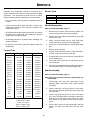
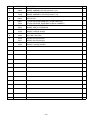
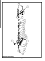
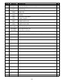
OPERATOR’S SAFETY AND SERVICE MANUAL SP80 SP125 SP160 This manual covers the following serial numbers and higher for each model listed: SP80 . . . . . . . . . . . . . . . . . . . . . 3830125 SP125 . . . . . . . . . . . . . . . . . . . . 3830125 SP160 . . . . . . . . . . . . . . . . . . . . 3830125 SOIL PICK MBW, Inc. 250 Hartford Rd • PO Box 440 Slinger, WI 53086-0440 Phone: (262) 644-5234 Fax: (262) 644-5169 Email: [email protected] Website: www.mbw.com MBW (UK) Ltd. MBW France S.A.R.L Units 2 & 3 Cochrane Street Bolton BL3 6BN, England Phone: 01204 387784 Fax: 01204 387797 Phone: +33 (0) 3 44 07 15 96 Fax: +33 (0) 3 44 07 41 28 L3847 / 07.15.N ©MBW, Inc. 2015 Printed in the USA TABLE OF CONTENTS Safety Information . . . . . . . . . . . . . . . . . . . . . . 1 Tips & Tricks. . . . . . . . . . . . . . . . . . . . . . . . . . . . . . . . 4 Introduction . . . . . . . . . . . . . . . . . . . . . . . . . . . . . . . . . 1 Service. . . . . . . . . . . . . . . . . . . . . . . . . . . . . . . . 6 Safety Precautions . . . . . . . . . . . . . . . . . . . . . . . . . . . 1 Safety Decals . . . . . . . . . . . . . . . . . . . . . . . . . . . . . . . 1 Specifications. . . . . . . . . . . . . . . . . . . . . . . . . . 3 Operation . . . . . . . . . . . . . . . . . . . . . . . . . . . . . 4 Introduction . . . . . . . . . . . . . . . . . . . . . . . . . . . . . . . . . 4 Before Starting & Operating . . . . . . . . . . . . . . . . . . . . 4 Torque Chart . . . . . . . . . . . . . . . . . . . . . . . . . . . . . . . 6 Service Tools . . . . . . . . . . . . . . . . . . . . . . . . . . . . . . . 6 Handle Disassembly. . . . . . . . . . . . . . . . . . . . . . . . . . 6 Handle Assembly . . . . . . . . . . . . . . . . . . . . . . . . . . . . 6 Parts Replacement Cycles and Tolerances . . . . . . . . 7 Replacement Parts . . . . . . . . . . . . . . . . . . . . . . 9 Connecting to Air Compressor . . . . . . . . . . . . . . . . . . 4 Main Assembly . . . . . . . . . . . . . . . . . . . . . . . . . . . . . 10 Starting Soil Pick. . . . . . . . . . . . . . . . . . . . . . . . . . . . . 4 Handle Assembly . . . . . . . . . . . . . . . . . . . . . . . . . . . 12 Operating . . . . . . . . . . . . . . . . . . . . . . . . . . . . . . . . . . 4 Stopping Soil Pick. . . . . . . . . . . . . . . . . . . . . . . . . . . . 4 Warranty . . . . . . . . . . . . . . . . . . . . . . . . . . . . . 14 This page intentionally left blank. SAFETY INFORMATION Introduction SAFE DRESS: Do not wear loose clothing, rings, wristwatches, etc. near machinery. This Safety Alert Symbol is used to call attention to items or operations which may be dangerous to those operating or working with this equipment. The symbol can be found throughout this manual and on the unit. Please read these warnings and cautions, along with all decals, carefully before attempting to operate the unit. Make sure every individual who operates or works with this equipment is familiar with all safety precautions. NOISE PROTECTION: Wear OSHA specified hearing protection devices. EYE PROTECTION: Wear OSHA specified eye shields, safety glasses, and sweat bands. FOOT PROTECTION: Wear OSHA specified steel-tipped safety shoes. WARNING HEAD PROTECTION: Wear OSHA specified safety helmets. GENERAL WARNING. Indicates information important to the proper operation of the equipment. Failure to observe may result in damage to the equipment and/or severe bodily injury or death. DUST PROTECTION: Wear OSHA specified dust mask or respirator. CAUTION OPERATOR: Keep children and bystanders off and away from the equipment. GENERAL CAUTION. Indicates information important to the proper operation of the equipment. Failure to observe may result in damage to the equipment. REFERENCES: For details on safety rules and regulations in the United States, contact your local Occupational Safety and Health Administration (OSHA) office. Equipment operated in other countries must be operated and serviced in accordance and compliance with any and all safety requirements of that country. The publication of these safety precautions is done for your information. MBW does not by the publication of these precautions, imply or in any way represent that these are the sum of all dangers present near MBW equipment. If you are operating MBW equipment, it is your responsibility to insure that such operation is in full accordance with all applicable safety requirements and codes. All requirements of the United States Federal Occupational Safety and Health Administration Act must be met when operated in areas that are under the jurisdiction of that United States Department. Safety Precautions LETHAL EXHAUST GAS: An internal combustion engine discharges carbon monoxide, a poisonous, odorless, invisible gas. Death or serious illness may result if inhaled. Operate only in an area with proper ventilation. NEVER OPERATE IN A CONFINED AREA! DANGEROUS FUELS: Use extreme caution when storing, handling and using fuels, as they are highly volatile and explosive in vapor state. Do not add fuel while engine is running. Stop and cool the engine before adding fuel. DO NOT SMOKE! Safety Decals SAFETY GUARDS: It is the owner's responsibility to ensure that all guards and shields are in place and in working order. Carefully read and follow all safety decals. Keep them in good condition. If decals become damaged, replace as required. If repainting the unit, replace all decals. Decals are available from authorized MBW distributors. Order the decal set listed on the following page(s). IGNITION SYSTEMS: Breakerless, magneto, and battery ignition systems can cause severe electrical shocks. Avoid contacting these units or their wiring. -1- US PATENT #5,170,943 MINIMIZE SCATTER BY KEEPING BOTTOM OF DEFLECTOR SHIELD THREE INCHES (3) ABOVE NOZZLE. PULL TRIGGER AND CHECK PRESSURE GAUGE. IF INDICATED PRESSURE IS NOT BETWEEN 100 AND 125 PSI (INDICATED BY A GREEN SECTION ON SOME GAUGES), INCREASE AIR SUPPLY BEFORE PROCEEDING. 17762 WARNING High pressure air/skin puncture hazard. Do not point nozzle at people. CAUTION Flying debris and loud noise hazard. Wear ear and eye protection. 17762 Safety Decals -2- SPECIFICATIONS 63 SP80 SP125 SP160 Volume of Air 80 cfm (38 L/s) 125 cfm (59 L/s) 160 cfm (76 L/s) Minimum Operating Pressure 100 psi (689 kPa) 100 psi (689 kPa) 100 psi (689 kPa) Maximum Operating Pressure 175 psi (1210 kPa) 175 psi (1210 kPa) 175 psi (1210 kPa) Exit Velocity 1476 mph (660 M/s) 1476 mph (660 M/s) 1476 mph (660 M/s) 4 in (10 cm) 4 in (10 cm) 8 in (20 cm) 6.7 lbs (3.0 kg) 6.7 lbs (3.0 kg) 6.7 lbs (3.0 kg) 100 dBA 100 dBA 100 dBA Cutting Edge 1 Operating Weight Noise Level2 1. Cutting edge will vary with different soil conditions. 2. Noise levels based upon normal operating conditions. Specifications subject to change without notice -3- OPERATION Introduction WARNING This parts manual contains only standard parts. Variations of these parts as well as other special parts are not included. Contact your local MBW distributor for assistance in identifying parts not included in this manual. Do not operate the Soil Pick at a pressure greater than 125 psi. 4. Before Starting & Operating Operating • REMEMBER! It is the owner’s responsibility to communicate information on the safe use and proper operation of this unit to the operators. WARNING • Review ALL of the Safety Precautions listed on page 1 of this manual. Always wear safety goggles and protection when operating Soil Pick. • Familiarize yourself with the operation of the machine and confirm that all controls function properly. • Know how to STOP the machine in case of an emergency. • Make sure hands, feet, and clothing are at a safe distance from any moving parts. For proper operation, the air supply must deliver the volume and pressure required for the Soil Pick model being used. Refer to Specifications, page 3 for minimum requirements. Start compressor and check pressure gage to verify proper operation of the compressor. 2. Connect air hose to compressor outlet and install safety clips if required. 3. Connect air hose to Soil Pick coupler and install safety clips if required. 4. Open compressor valve to pressurize Soil Pick. If the area to be excavated is covered with grass or other plant material, it may be easier to remove it with a shovel or rake before proceeding with the Soil Pick. 2. Hold the Soil Pick perpendicular to the soil surface to be worked. 3. With the nozzle in contact with the soil, pull the trigger momentarily to break up the soil in immediate contact with the nozzle tip. 4. While keeping the nozzle submerged in the loosened soil, hold the trigger down and work the nozzle in a circular motion. 5. As the soil is loosened and the Soil Pick is worked deeper into the ground, move the deflector up the barrel to minimize scatter. 6. After loosening the soil, it can be easily removed using an industrial vacuum system or using conventional methods. Stopping Soil Pick Starting Soil Pick 1. Close compressor valve to release supply pressure to Soil Pick. 2. Aim Soil Pick away from people, and pull the trigger to relieve all residual air pressure in the hose. 3. Disconnect air hose on both ends. 4. Turn compressor OFF. 5. Slowly open compressor valve to relieve air pressure in the tank. WARNING Never aim the Soil Pick at exposed skin or people. 1. Aim Soil Pick away from people, and pull the trigger. 2. If the pressure reading is less than 100 psi (indicated as a red section on some gages), the air pressure at the source must be increased. 3. hearing 1. Connecting to Air Compressor 1. Adjust the rubber deflector so the bottom of the cone is about three inches (3”) above the nozzle tip. Tips & Tricks If the pressure reading is greater than 125 psi, the air pressure at the source must be decreased to prevent damage and possible injury. 1. -4- The Soil Pick can be used alone for safe excavation on small jobs, or used as an underground locating and exposing tool in conjunction with higher production excavators, backhoes, and trenchers. 2. 3. 4. 7. The Soil Pick does not require lubrication. The air supply must be free of oil to achieve proper performance. 8. The Soil Pick is a selective excavator. The violent decompression of air is sufficient to loosen porous soil, but will have virtually no effect on non-porous objects such as buried utilities or plant roots. The Soil Pick is not designed as an impact or prying tool. The barrel is manufactured of a composite material designed to withstand high internal pressure. It is not designed to withstand prying or impact forces. 9. The Soil Pick has a cutting edge of four to eight inches, depending on the model. This means the nozzle must be kept close to the soil for the decompression to be effective. Beyond the cutting edge, substantial decompression has occurred and the Soil Pick becomes a highly effective blower for loose debris. The Soil Pick is an effective excavation tool even when there is no concerns of buried utilities. In most cases, productivity is enhanced dramatically compared to pick and shovel work. 10. The Soil Pick is highly effective when used to clean saw joints and cracks in concrete. It can grossly outperform a blow pipe, and provide a very clean surface for excellent sealant adhesion. The Soil Pick is not an elaborate blow pipe. Conventional blow pipes produce subsonic air stream velocities between 500 and 600 mph, and cannot provide the cutting edge required for soil excavation. Blow pipes can be used for moving loose debris, but even then are outperformed by the Soil Pick. 5. The Soil Pick will not cut through frost, but it will work well below the frost line. 6. The Soil Pick works extremely well in all types of granular soils and cohesive soils with a good granular gradation. The effectiveness will drop off as the granular component in cohesive soils decreases. Wet clay soils may be too plastic to loosen. 11. The Soil Pick is an effective tool for nursery applications. Because it is a selective excavator, it will not damage roots. Because it is an air tool, it is also aerating the soil while digging. 12. The Soil Pick has an almost endless list of uses. It can effectively clean barges, railroad cars, construction equipment, and more. It can be used for shallow trenching, post hole digging, stump removal, pothole preparation prior to patching, and many more unique applications. -5- SERVICE Assembly and disassembly should be performed by a service technician who has been factory trained on MBW equipment. The unit should be clean and free of debris. Pressure washing before disassembly is recommended. Service Tools 20563 VALVE GREASE, SILICONE,.21 oz • Prior to assembly, wash all parts in a suitable cleaner or solvent. 20565 REBUILD KIT, SOIL PICK Part No. Description Handle Disassembly • Check moving parts for wear and failure. Refer to the Replacement section in this manual for tolerance and replacement cycles. Refer to Handle Assembly, page 12. 1. Remove three screws (#18) securing handle and remove, taking care to not lose spring (#10). 2. • All bearings should be replaced when rebuilding any exciter or gearbox. Remove two screws (#15) holding bottom cover (#5) and remove cover. 3. Using a wrench across flats on valve spool (#4), loosen and remove screw securing trigger (#8). • All gaskets and seals should be replaced after any disassembly. 4. Use a pick or small screwdriver, remove shaft wiper (#2). 5. Remove snap ring (#15). 6. Using a wrench across the flats on valve spool (# 4), remove screw securing lower spool (#7). 7. Pull spool (#4) our the top of the body. Guide (#6) will come out with spool. 8. Push lower valve spool (#7) out the bottom of the valve body (#9). 9. Insert a long standard bladed screwdriver through the inlet of the valve body to unscrew the gage (#11). • All shafts and housings should be oiled prior to pressing bearings. Also, ensure that the bearings are pressed square and are seated properly. Torque Chart SIZE 1/4-20 1/4-28 5/16-18 5/16-24 3/8-16 3/8-24 7/16-14 7/16-20 1/2-13 1/2-20 9/16-12 5/8-11 5/8-18 3/4-16 1-8 1-14 1-1/2-6 M6 M8 M 10 GRADE 2 GRADE 5 49 in•lbs 76 in•lbs 56 in•lbs 87 in•lbs 8 ft•lbs 13 ft•lbs 9 ft•lbs 14 ft•lbs 15 ft•lbs 23 ft•lbs 17 ft•lbs 26 ft•lbs 24 ft•lbs 37 ft•lbs 27 ft•lbs 41 ft•lbs 37 ft•lbs 57 ft•lbs 41 ft•lbs 64 ft•lbs 53 ft•lbs 82 ft•lbs 73 ft•lbs 112 ft•lbs 83 ft•lbs 112 ft•lbs 144 ft•lbs 200 ft•lbs 188 ft•lbs 483 ft•lbs 210 ft•lbs 541 ft•lbs 652 ft•lbs 1462 ft•lbs 3 ft•lbs 4 ft•lbs 6 ft•lbs 10 ft•lbs 10 ft•lbs 20 ft•lbs CONVERSIONS in•lbs x 0.083 = ft•lbs ft•lbs x 12 = in•lbs ft•lbs x 0.1383 = kg•m ft•lbs x 1.3558 = N•m GRADE 8 9 ft•lbs 10 ft•lbs 18 ft•lbs 20 ft•lbs 33 ft•lbs 37 ft•lbs 52 ft•lbs 58 ft•lbs 80 ft•lbs 90 ft•lbs 115 ft•lbs 159 ft•lbs 180 ft•lbs 315 ft•lbs 682 ft•lbs 764 ft•lbs 2371 ft•lbs 7 ft•lbs 18 ft•lbs 30 ft•lbs Handle Assembly Refer to Handle Assembly, page 12. Note: All o-rings and seals should be replaced after any disassembly. -6- 1. Thread gage (#11) into body (#9) using a long standard blade screwdriver and thread sealing compound. 2. Place o-rings (#12, 14) into grooves on valve spool (#4). Coat o-rings with grease and insert spool (#4) into body (#9). 3. Place o-ring (#14) into groove on lower valve spool (#7), coat o-ring with grease, and insert into bottom of body. Secure to valve spool (#14) with screw (#17). Use wrench across flats on valve spool to tighten screw. 4. Place o-ring in groove on upper guide (#6), coat with grease, and insert into main body over the valve spool. 5. Insert retaining ring (#15) and make certain it is fully seated in groove. 8. Attach Handle (#3) to body with three screws (#17). Use Medium strength loctite on these screws. 6. Coat the inner diameter of the dust wiper (#2) with grease and insert into main body. The lip of the seal should be facing out, and the shoulder should be flush with the surface of the body. 9. Assemble lower cover (#5) to body with two screws (#15) 7. 10. Test action of trigger to ensure complete closing of valve after trigger is released. Attach trigger (#8) to valve spool with screw (#17). Do not overtighten screw. place spring in the well of the trigger (#8). Parts Replacement Cycles and Tolerances Bearings Replace anytime a bearing is rough, binding, discolored or removed from housing or shaft. Hardware Replace any worn or damaged hardware as needed. Replacement hardware should be grade 5 and zinc plated unless otherwise specified. Safety Decals Replace if they become damaged or illegible. Seals & Gaskets Replace if a leak is detected and at every overhaul or teardown. -7- This page intentionally left blank. -8- REPLACEMENT PARTS The warranty is stated in this book on page 14. Failure to return the Warranty Registration Card renders the warranty null and void. '(&$//2&$7,21 MBW has established a network of reputable distributors/ dealers with trained mechanics and full facilities for maintenance and rebuilding, and to carry an adequate parts stock in all areas of the country. Their sales engineers are available for professional consultation. If you cannot locate an MBW distributor in your area, contact MBW or one of our Sales Branches listed below. When ordering replacement parts, be sure to have the following information available: • Model and Serial Number of machine when ordering MBW parts • Model and Serial Number of engine when ordering engine parts • Part Number, Description, and Quantity The unit’s serial number can be found in the following locations: • Company Name, Address, Zip Code, and Purchase Order Number • The serial number decal is located on the handle body adjacent to the pressure gage. • Preferred method of shipping REMEMBER - You own the best! If repairs are needed, use only MBW parts purchased from authorized MBW distributors. Write Model Number here Write Serial Number here Contact Information MBW, Inc. MBW (UK) Ltd. MBW France S.A.R.L 250 Hartford Rd • PO Box 440 Slinger, WI 53086-0440 Phone: (262) 644-5234 Fax: (262) 644-5169 Email: [email protected] Website: www.mbw.com Units 2 & 3 Cochrane Street Bolton BL3 6BN, England Phone: 01204 387784 Fax: 01204 387797 Phone: +33 (0) 3 44 07 15 96 Fax: +33 (0) 3 44 07 41 28 -9- ACCESSORIES Main Assembly - 10 - ITEM 1. 2. 3. 4. 5. 6. 7. 8. 9. 10. PART NO. 01291 03820 03813 17594 03817 03829 03841 17599 03848 03849 17748 17749 17750 19358 19750 19751 19749 19752 20450 DESCRIPTION CABLE TIE BARREL ASSEMBLY, 80 CFM (Includes 1,3,4) BARREL ASSEMBLY, 125 CFM (Includes 1,3,4) BARREL ASSEMBLY, 160 CFM (Includes 1,3,4) O-RING DEFLECTOR FITTING, COUPLER DIXON AM-7 (CLAW COUPLER) FITTING, COUPLER, DIXON DML12 (QUICK CONNECT) BARREL ASM, 42” EXTENSION BARREL ASM, 21” EXTENSION NOZZLE, 80CFM, 45 DEG NOZZLE, 125CFM, 45 DEG NOZZLE, 160CFM, 45 DEG KIT, CASE, SOIL PICK NOZZLE, 65 CFM, 90 DEG NOZZLE, 80 CFM, 90 DEG NOZZLE, 125 CFM, 90 DEG NOZZLE, 160 CFM, 90 DEG HANDLE ASM, ERGO - 11 - QTY 1 1 1 1 1 1 1 1 1 1 1 1 1 1 1 1 1 1 1 Handle Assembly - 12 - ITEM 1. 2. 3. 4. 5. 6. 7. 8. 9. 10. 11. 12. 13. 14. 15. 16. 17. 18. PART NO. 17250 19430 20451 20452 20453 20454 20455 20456 20457 20459 20460 20461 20462 20463 20587 F023202BCS F033205BCS F042006BCS 20565 DESCRIPTION FITTING, PLUG SHAFT WIPER SEAL, 3/4 ID X 1-1/8 OD HANDLE, SOIL PICK VALVE SPOOL COVER, BOTTOM GUIDE, TOP BOTTOM SPOOL (20455: before SN 3830125 use 20677) TRIGGER VALVE BODY, MACHINED SPRING, TRIGGER GAGE, SLOTTED O-RING, 9/16 ID X .125 O-RING, 1 ID X .0625 O-RING, 5/8 ID X .0625 RETAINING RING, INT. 1.125 BCS, TORX, #8-32 X 1/4” BCS, TORX, #10-32 X 5/8” BCS, TORX, 1/4-20 X 3/4” REBUILD KIT, SOIL PICK (CONTAINS 2, 12, 13, 14) - 13 - QTY 1 1 1 1 1 1 1 1 1 1 1 1 1 2 1 2 2 3 WARRANTY WHAT DOES THIS WARRANTY COVER? MBW, Incorporated (MBW) warrants each New Machine against defects in material and workmanship for a period of twelve (12) months. "New Machine" means a machine shipped directly from MBW or authorized MBW dealer to the end user. This warranty commences on the first day the machine is sold, assigned to a rental fleet, or otherwise put to first use. MBW warrants each Demonstration Machine against defects in material and workmanship for a period of six (6) months. "Demonstration Machine" means a machine used by MBW or its agents for promotional purposes. This warranty commences on the first day the machine is sold, assigned to a rental fleet, or otherwise put to first use. This warranty covers the labor cost for replacement or repair of parts, components, or equipment on New Machines or Demonstration Machines, and MBW shall pay labor costs at MBW's prevailing rate to affect the warranted repair or replacement. MBW reserves the right to adjust labor claims on a claim-by-claim basis. This warranty covers the shipping cost of replacement parts, components, or equipment via common ground carriers from MBW to an authorized MBW dealer. Air freight is considered only in cases where ground transportation is not practical. MAY THIS WARRANTY BE TRANSFERRED? This warranty is nontransferable and only applies to the original end user of a new machine or demonstration machine. WHAT DOES THIS WARRANTY NOT COVER? 1.This warranty does not cover any Used Equipment. "Used Equipment" means any MBW machine or equipment that is not a New Machine or a Demonstration Machine. All Used Equipment is sold AS IS/WHERE IS WITH ALL FAULTS. 2.This warranty does not cover any New Machine, Demonstration Machine, or their equipment, parts, or components altered or modified in any way without MBW's prior written consent. This warranty does not cover the use of parts not specifically approved by MBW for use on MBW products. This warranty does not cover misuse, neglect, shipping damage, accidents, acts of God, the operation of any New Machine or Demonstration Machine in any way other than recommended by MBW in accordance with its specifications, or any other circumstances beyond MBW's control. This warranty does not cover any New Machine or Demonstration Machine repaired by anyone other than MBW factory branches or authorized MBW distributors. 3.This warranty does not cover, and MBW affirmatively disclaims, liability for any damage or injury resulting directly or indirectly from design, materials, or operation of a New Machine or Demonstration Machine or any other MBW product. MBW's liability with respect to any breach of warranty shall be limited to the provisions of this document and in no event shall exceed an amount equal to the purchase price of the New Machine or Demonstration Machine purchased from MBW. 4.This warranty does not cover engines, motors, and other assemblies or components produced by other manufacturers and used on a New Machine or Demonstration Machine, as said engines, motors, and other assemblies or components may have warranties provided by the manufacturer thereof. This warranty does not apply to consumable items, such as v-belts, filters, trowel and screed blades, seals, shock mounts, batteries, and the like, all of which are sold AS IS/WHERE IS WITH ALL FAULTS. 5.This warranty does not cover the cost of transportation and other expenses which may be connected with warranty service but not specifically mentioned herein. 6.This warranty does not cover any updates to any New Machine, Demonstration Machine, or any other MBW product. MBW reserves the right to improve or make product changes without incurring any obligation to update, refit, or install the same on New Machines or Demonstration Machines previously sold. WHAT MUST YOU DO TO OBTAIN WARRANTY COVERAGE? Each New Machine or Demonstration Machine is accompanied by a Warranty Registration Card. You must sign, date, and return the Warranty Registration Card to the place of origin of the New Machine or Demonstration Machine, either to MBW, Inc. at P.O. Box 440, Slinger, Wisconsin 53086, MBW (UK), Ltd. at Units 2 & 3 Cochrane Street, Bolton BL3 6BN, United Kingdom or MBW FRANCE SARL at ZA D'Outreville, 5 Rue Jean Baptiste Neron, Bornel 60540 France, within ten (10) days after purchase, assignment to a rental fleet, or first use. This signed warranty card is the buyer's affirmation that he has read, understood, and accepted the warranty at the time of purchase. Failure to return the warranty card as specified herein renders the warranty null and void. In order to receive warranty coverage consideration, warranty claims must be submitted within thirty (30) days after the New Machine or Demonstration Machine fails. Warranty claims must be submitted to MBW, Inc., MBW (UK), Ltd. or MBW FRANCE SARL, and written authorization for the return of merchandise or parts under the warranty must be obtained before shipment to MBW. WHAT WILL MBW DO? MBW's obligation under this warranty is limited to the replacement or repair of parts for a New Machine or Demonstration Machine at MBW factory branches or at authorized MBW distributors, and such replacement or repair is the exclusive remedy provided hereunder. Labor must be performed at an authorized MBW distributor. MBW reserves the right to inspect and render a final decision on each warranty case, and MBW's repair or replacement is solely within the discretion of MBW. IT IS EXPRESSLY AGREED THAT THIS SHALL BE THE SOLE AND EXCLUSIVE REMEDY UNDER THIS WARRANTY. UNDER NO CIRCUMSTANCES SHALL MBW BE LIABLE FOR ANY COSTS, LOSS, EXPENSE, DAMAGES, SPECIAL DAMAGES, INCIDENTAL DAMAGES, OR PUNITIVE DAMAGES ARISING DIRECTLY OR INDIRECTLY FROM THE USE OF THE NEW MACHINE OR DEMONSTRATION MACHINE WHETHER BASED UPON WARRANTY, CONTRACT, NEGLIGENCE, STRICT LIABILITY, OR ANY OTHER LEGAL THEORY. THE FOREGOING WARRANTY IS EXPRESSLY IN LIEU OF ALL OTHER WARRANTIES, EXPRESS OR IMPLIED, INCLUDING THE WARRANTIES OF MERCHANTABILITY, FITNESS FOR USE, AND FITNESS FOR A PARTICULAR PURPOSE, AND ALL OTHER OBLIGATIONS OR LIABILITY ON MBW'S PART. MBW NEITHER ASSUMES NOR AUTHORIZES ANY OTHER PERSON TO ASSUME ON BEHALF OF MBW ANY OTHER LIABILITY OR WARRANTY IN CONNECTION WITH THE SALE OR SERVICE OF ANY NEW MACHINE, DEMONSTRATION MACHINE , OR ANY OTHER MBW PRODUCT. EXTENDED RAMMER WARRANTY - MODELS R422, R442, R482 & R483. This extended warranty commences on the last day of MBW’s standard, one year, “limited warranty” and runs for an additional four years (48 months). This extended warranty is limited to part replacement and shipping costs of rammer bellows and non-metallic slide bearings only. This extended warranty does not cover labor, down time, or any other cost beyond that of component replacement and freight. This extended warranty is subject to all limitations set fourth in MBW’s “limited warranty”, above. - 14 -