1
MODELS
DV 18DL
DV 14DL
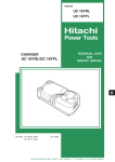
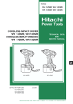
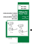
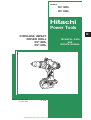
Hitachi
Power Tools
CORDLESS IMPACT
DRIVER DRILL
DV 18DL
DV 14DL
LIST Nos. DV 18DL: G853
DV 14DL: G854
D
TECHNICAL DATA
AND
SERVICE MANUAL
Jul. 2006
SPECIFICATIONS AND PARTS ARE SUBJECT TO CHANGE FOR IMPROVEMENT
REMARK:
Throughout this TECHNICAL DATA AND SERVICE MANUAL, a symbol(s)
is(are) used in the place of company name(s) and model name(s) of our
competitor(s). The symbol(s) utilized here is(are) as follows:
Competitor
Symbol Utilized
Company Name
Model Name
C-1
MAKITA
BHP451
C-2
MAKITA
BHP440
CONTENTS
Page
1. PRODUCT NAME .............................................................................................................................. 1
2. MARKETING OBJECTIVE ................................................................................................................ 1
3. APPLICATIONS ................................................................................................................................. 1
4. SELLING POINTS ............................................................................................................................. 2
4-1. Selling Point Descriptions ................................................................................................................... 3
5. SPECIFICATIONS ............................................................................................................................. 7
5-1. Model DV 18DL .................................................................................................................................. 7
5-2. Model DV 14DL .................................................................................................................................. 8
6. COMPARISONS WITH SIMILAR PRODUCTS ................................................................................. 9
6-1. Model DV 18DL .................................................................................................................................. 9
6-2. Model DV 14DL ................................................................................................................................ 10
7. WORKING PERFORMANCE PER SINGLE CHARGE .................................................................... 11
7-1. Model DV 18DL ................................................................................................................................ 11
7-2. Model DV 14DL ................................................................................................................................ 12
8. PRECAUTIONS IN SALES PROMOTION ...................................................................................... 13
8-1. Safety Instructions ............................................................................................................................ 13
8-2. Inherent Drawbacks of Cordless Impact Driver Drills Requiring Particular Attention During Sales
Promotion .......................................................................................................................................... 15
9. REFERENCE MATERIALS ............................................................................................................. 16
9-1. Speed Control Mechanism ............................................................................................................... 16
10. REPAIR GUIDE ............................................................................................................................. 17
10-1. Precautions in Disassembly and Reassembly ................................................................................ 17
10-2. Precaution in Disassembly and Reassembly of Battery Charger ................................................... 27
11. STANDARD REPAIR TIME (UNIT) SCHEDULES......................................................................... 28
Assembly Diagram for DV18DL
Assembly Diagram for DV14DL
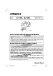
1. PRODUCT NAME
Hitachi 18 V Cordless Impact Driver Drill/Cordless Hammer Drill, Model DV 18DL
Hitachi 14.4 V Cordless Impact Driver Drill/Cordless Hammer Drill, Model DV 14DL
2. MARKETING OBJECTIVE
The Models DV 18DL and DV 14DL are the excellent, top-quality cordless impact driver drills developed to
reinforce our 18-V and 14.4-V product lines and also to meet the market demands. Each of these models is
equipped with a lithium-ion battery. The Model DV 18DL is compact and lightweight thanks to the new cyber
design. The overall length is 250 mm and the weight is 2.2 kg. While the Model DV 18DL is 3 mm shorter and
0.4 kg lighter than the conventional Model DV 18DMR, it provides the class-top maximum torque 64 N•m thanks to
the optimally designed motor and mechanical unit. Features of the Models DV 18DL and DV 14DL include the
following:
Powerful motor equipped with a large radial fan
Sturdy metal chuck and metal clutch cap
Selectable rotation speed in four steps with the shift knob and the change lever
Soft-grip handle widely covered with elastomer
Angle-adjustable one-touch hook
Replaceable carbon brushes and armature thanks to the same separate-type motor as an impact driver drill
with cord
Interchangeable with conventional NiCd or NiMH batteries
Thus the Models DV 18DL and DV 14DL are excellent in performance, operability and maintainability.
3. APPLICATIONS
Tightening and loosening wood screw, self-tapping screw and machine screw
Drilling into wood, plastic, mild steel and aluminum materials
Drilling into brick and concrete block
--- 1 ---
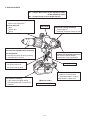
4. SELLING POINTS
No. 1 torque: Max. torque 64 N•m (Model DV 18DL)
52 N•m (Model DV 14DL)
No. 1 compact body: Overall length 250 mm
22-position torque adjustable clutch
Fine torque adjustment
3-mode selection
Drill
Impact drill
Driver
Side handle
13 mm keyless chuck is operable with
one hand and equipped with ratcheting
lock mechanism
Prevents the driver bit from loosening
Operable with one hand
Externally replaceable carbon
brushes and separate-type motor
The carbon brushes and the
armature are singly replaceable.
Four-speed selection
Two-speed shift knob
Two-speed change lever
New lithium-ion battery
Light weight and stable design
Interchangeable with conventional
batteries
Improved overload durability
(improved cooling efficiency)
Large radial fan
Optimally designed cooling air path
Soft-grip handle
One-touch hook
Ready for use at anytime
(angle-adjustable in 5 steps)
Mountable on either side
[Model DV 18DL]
With injection-molded case
--- 2 ---
4-1. Selling Point Descriptions
4-1-1. Compact and high power: Max. torque 64 N•m (Model DV 18DL)
While the Model DV 18DL is compact and lightweight (overall length 250 mm, weight 2.2 kg), it provides the classtop maximum torque 64 N•m thanks to the optimum design (see Tables 1 and 2). The Models DV 18DL and
DV 14DL can drill large diameter holes and tighten screws effortlessly.
Table 1
Model
DV 18DL
DV 18DMR
DV 18DV
C-1
Max. torque [N•m]
64
62
45
63
Overall length [mm]
250
253
242
250
Overall height [mm]
248
248
247
257
Overall width [mm]
82
76
76
78
Weight [kg]
2.2
2.7
2.5
2.2
Table 2
Model
DV 14DL
DV 14DMR
DV 14DV
C-2
Max. torque [N•m]
52
52
39
25
Overall length [mm]
250
253
242
204
Overall height [mm]
246
245
242
242
Overall width [mm]
78
76
76
79
Weight [kg]
2.1
2.5
2.2
1.7
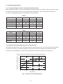
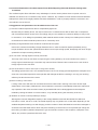
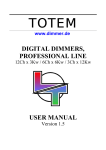
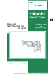
4-1-2. Improved overload durability (improved cooling efficiency)
The Models DV 18DL and DV 14DL are equipped with the separate-type motor. To improve the overload durability
in continuous operation, the optimally designed cooling air path that is descended from the Model DS 12DM
increases the cooling efficiency as well as the large radial fan increases the volume of air. (See Fig.1.)
Temperature rise outside the motor
2.6 N.m {21 kgf.cm} intermittent load test [20 cycles/minute operation]
120
DV 18DV
100
80
DS 18DL, DS 18DMR
60
40
20
: Saturated (no abnormality)
0
0
20
40
60
Time (minute)
Fig. 1 Curves of motor temperature rise
--- 3 ---
80
4-1-3. 22-position torque adjustable clutch
The 22-stage clutch ensures fine torque adjustment. (See Table 3.) The tightening torque is selectable up to 7 N•m.
The wider torque selectable range extends the range of applicable works.
Table 3
Tightening torque
1.5 0.5 N•m {15 5 kgf•cm}
2.3 0.6 N•m {23 6 kgf•cm}
3.0 0.7 N•m {31 7 kgf•cm}
3.8 0.8 N•m {39 8 kgf•cm}
6.2 0.9 N•m {62 9 kgf•cm}
7 1.0 N•m {70 10 kgf•cm}
Clutch cap position
1
4
7
10
19
22
*There may be difference in operation depending on the screw shapes and workpieces.
Perform a test before actual driving.
4-1-4. 13 mm keyless chuck is operable with one hand and equipped with ratcheting lock mechanism
The sleeve can be turned with one hand. The driver bits can be easily replaced by holding the main unit with one
hand while turning the sleeve with other hand. The Models DV 18DL and DV 14DL are also equipped with the
ratcheting lock mechanism to prevent the sleeve from loosening during operation. A simple twist until a click is
heard locks the sleeve tight.
4-1-5. Four-speed selection
The rotation speed is selectable from four steps with the shift knob (two-speed gear) and the rotation change lever
(two-speed switch) for various applications such as tightening small-diameter screws and drilling.
When the rotation change lever is slid to the lower side, the power mode (P) is set and when slid to the upper
side, the save mode (S) is set.
Save mode (S)
Rotation change lever
Power mode (P)
4-1-6. Soft-grip handle
The handles are widely covered with soft-touch elastomer (rubber-like soft resin). It is slip-resistant and securely
fits in the palm of a hand even if the gripping hand sweats.
--- 4 ---
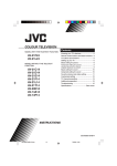
4-1-7. One-touch hook
(1) The hook can be quickly slid out whenever necessary and slid in when not necessary.
(2) The hook is mountable on either side using a flat-blade screwdriver or a coin.
(3) The angle of the hook is adjustable in five steps.
Angle-adjustable in 5 steps
Mountable on either side
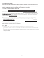
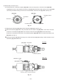
4-1-8. Externally replaceable carbon brushes and separate-type motor
The carbon brushes are replaceable from the outside. In addition, the armature is singly replaceable through the
adoption of the separate-type motor that is the same as a driver drill with a power cord. Thus the Models DV 18DL
and DV 14DL are easier to maintain.
Carbon brush
Armature
Magnet
Separate-type motor
[Models DV 18DL and DV 14DL]
--- 5 ---
4-1-9. New Lithium-ion battery
Each of the Types EBM 1830 and EBL 1430 lithium-ion batteries is equipped with the overdischarge protection
circuit, overload protection circuit, and voltage monitoring circuit for each cell to prevent reduction of the battery
life due to overdischarge (overuse) or overcharge (excessive charging) of the battery.
The number of charging/discharging is about 1,500.
Precautions for use of the Types EBM 1830 and EBL 1430 lithium-ion batteries
Each of the Types EBM 1830 and EBL 1430 lithium-ion batteries is equipped with a protective function that
automatically stops output to extend the battery life. The motor may stop automatically in either of the following
case 1 or 2 even if the switch is depressed continuously during operation. This is because the protective
function is activated. The battery is not faulty.
1
The motor may stop automatically when the remaining battery level is low (when the battery voltage is
decreased to about 12 V (Type EBM 1830)/when decreased to about 8 V (Type EBL 1430)). Charge the
battery immediately in such case.
2
The motor may stop if the Model DV 18DL/DV 14DL is overloaded. In such case, release the switch and
eliminate the cause of the overload problem. Then the Model DV 18DL/DV 14DL is operable.
Please instruct the customers on the above precautions.
4-1-10. Others
The Models DV 18DL and DV 14DL have the following features common to the previous models.
The terminal is movable according to the movement of the battery to prevent damage to the contact portion.
The contact between the housing and the battery is changed from line contact to surface contact to minimize
rattling due to wear.
--- 6 ---
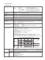
5. SPECIFICATIONS
5-1. Model DV 18DL
Capacity
Screw driving Machine screw .........
Wood screw .............
Drilling
Brick .........................
Metal ••• Mild steel .....
Aluminum ....
Wood ........................
6 mm (1/4")
8 mm dia. x 100 mm (#20 x 4")
16 mm (5/8") [Depth 30 mm (1-1/4")]
13 mm (1/2") [Thickness 1.6 mm (1/16")]
13 mm (1/2") [Thickness 1.6 mm (1/16")]
50 mm (2") [Thickness 18 mm (11/16")]
Keyless chuck
(13VLRL-N)
Mount type ........ Screw-on (UNF 1/2" --- 20)
Diameter............ 1.5 --- 13 mm (1/16" --- 1/2")
Rotation speed (No-load)
Low: 0 --- 200/400/min, High: 0 --- 900/1,800/min.
Torque
Slip torque ..... 1.5 -- 7 N•m (15 -- 70 kgf•cm, 13 -- 61 in-lbs.) [22 stages]
Max. torque ..... Low: 64 N•m (653 kgf•cm, 570 in-lbs.), High: 14 N•m (143 kgf•cm, 124 in-lbs.)
Type of motor
Fan cooled DC magnet motor
Type of switch
Trigger switch with push button for forward and reverse rotation changeover (with brake)
Handle configuration
T-type (with soft-grip handle)
Enclosure
Body ........ Glassfiber reinforced polycarbonate resin (black) and thermoplastic elastomer (green)
Battery ..... Glassfiber reinforced polycarbonate resin (black)
Charger ... ABS resin (black)
Sealed cylindrical lithium-ion storage battery
Nominal voltage .......... DC 18V
Nominal life ................. Charging/discharging: Approx. 1,500 times
Nominal capacity ......... 3.0 Ah
Overcharge protection system:
(1) Battery voltage detection (- V system)
Battery temperature detection (dT/dt system) for Ni-MH and SUPER Ni-MH
batteries
(2) Battery surface temperature detection (thermistor)
(3) 120-minute timer
(4) Stop current detection (Li-ion batteries)
Power input: 95 W
Charging time: Approx. 45 minutes [for Type EBM 1830 battery at 20ûC (68ûF)]
Operable ambient temperature range: 0ûC --- 40ûC (32ûF --- 104ûF)
The maximum allowable temperature of the Type EBM 1830 battery is 50ûC (122ûF)
Battery
(Type EBM 1830)
Charger
(Model UC 18YRL)
Indication method of battery charging function
Indication of the pilot lamp
Charge status
lamp (Red)
Before
charging
Blinks
(Red)
0.5 sec. ON
While
charging
Lights
(Red)
Stays ON continuously
Charging
completed
Blinks
(Red)
0.5 sec. ON
0.5 sec. OFF
Charging
impossible
Flickers
(Red)
0.1 sec. ON
0.1 sec. OFF
Lights
(Green)
Stays ON continuously
Overheat lamp Overheat
standby
(Green)
0.5 sec. OFF
Malfunction in the battery
or the charger.
Battery overheated.
Unable to charge.
(Charging will commence
when battery is cooled.)
NOTE: When standby for cooling the battery, the Model UC 18YRL cools the overheated battery by the
cooling fan.
Weight
Standard
accessories
Net
Main body unit (including battery) .................................................... 2.2 kg (4.8 lbs.)
Charger unit (UC 18YRL, including cord) ........................................ 0.6 kg (1.3 lbs.)
Gross
DV 18DL (2 MRK) ............................................................................ 6.4 kg (14.1 lbs.)
(2MRK)
Charger (UC 18YRL) ..............................................................................................
Battery (EBM 1830)................................................................................................
Phillips (plus) driver bit (No. 2) ...............................................................................
Side handle ............................................................................................................
Case (injection-molded) .........................................................................................
--- 7 ---
1
2
1
1
1
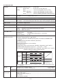
5-2. Model DV 14DL
Capacity
Screw driving Machine screw .........
Wood screw .............
Drilling
Brick .........................
Metal ••• Mild steel ......
Aluminum .....
Wood ........................
Keyless chuck
(13VLRL-N)
Mount type ........ Screw-on (UNF 1/2" --- 20)
Diameter ............ 1.5 --- 13 mm (1/16" --- 1/2")
Rotation speed (No-load)
Low: 0 --- 200/400/min., High: 0 --- 850/1,750/min.
Torque
Slip torque ..... 1.5 -- 7.0 N•m (15 -- 70 kgf•cm, 13 -- 61 in-lbs.) [22 stages]
Max. torque ..... Low: 52 N•m (530 kgf•cm, 460 in-lbs.), High: 12 N•m (122 kgf•cm, 89 in-lbs.)
Type of motor
Fan cooled DC magnet motor
Type of switch
Trigger switch with push button for forward and reverse rotation changeover (with brake)
Handle configuration
T-type (with soft-grip handle)
Enclosure
Body ........ Glassfiber reinforced polycarbonate resin (black) and thermoplastic elastomer (green)
Battery ..... Glassfiber reinforced polycarbonate resin (black)
Charger ... ABS resin (black)
Sealed cylindrical nickel-cadmium storage battery
Nominal voltage .......... DC 14.4V
Nominal life ................. Charging/discharging: Approx. 1,500 times
Nominal capacity ......... 3.0 Ah
Battery
(Type EBL 1430)
Charger
(Model UC 18YRL)
6 mm (1/4")
8 mm dia. x 75 mm (#20 x 3")
14 mm (9/16") [Depth 30 mm (1-1/4")]
13 mm (1/2") [Thickness 1.6 mm (1/16")]
13 mm (1/2") [Thickness 1.6 mm (1/16")]
45 mm (1-25/32") [Thickness 18 mm (11/16")]
Overcharge protection system:
(1) Battery voltage detection (- V system)
Battery temperature detection (dT/dt system) for Ni-MH and SUPER Ni-MH
batteries
(2) Battery surface temperature detection (thermistor)
(3) 120-minute timer
(4) Stop current detection (Li-ion batteries)
Power input: 95 W
Charging time: Approx. 45 minutes [for Type EBL 1430 battery at 20ûC (68ûF)]
Operable ambient temperature range: 0ûC --- 40ûC (32ûF --- 104ûF)
The maximum allowable temperature of the Type EBL 1430 battery is 50ûC (122ûF)
Indication method of battery charging function
Indication of the pilot lamp
Charge status
lamp (Red)
Before
charging
Blinks
(Red)
0.5 sec. ON
While
charging
Lights
(Red)
Stays ON continuously
Charging
completed
Blinks
(Red)
0.5 sec. ON
0.5 sec. OFF
Charging
impossible
Flickers
(Red)
0.1 sec. ON
0.1 sec. OFF
Lights
(Green)
Stays ON continuously
Overheat lamp Overheat
standby
(Green)
0.5 sec. OFF
Malfunction in the battery
or the charger.
Battery overheated.
Unable to charge.
(Charging will commence
when battery is cooled.)
NOTE: When standby for cooling the battery, the Model UC 18YRL cools the overheated battery by the
cooling fan.
Weight
Standard
accessories
Net
Main body unit (including battery) .................................................... 2.1 kg (4.6 lbs.)
Charger unit (UC 18YRL, including cord) ........................................ 0.6 kg (1.3 lbs.)
Gross
DV 14DL (2 LRK) ............................................................................. 6.2 kg (13.7 lbs.)
(2LRK)
Charger (UC 18YRL)..............................................................................................
Battery (EBL 1430) .................................................................................................
Phillips (plus) driver bit (No. 2) ...............................................................................
Side handle ............................................................................................................
Case (injection-molded) .........................................................................................
--- 8 ---
1
2
1
1
1
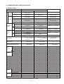
6. COMPARISONS WITH SIMILAR PRODUCTS
6-1. Model DV 18DL
HITACHI
Maker
Model
C-1
DV 18DL
DV 18DMR
6 mm (1/4")
6 mm (1/4")
6 mm (1/4")
8 mm dia. x 100 mm
(# 20 x 4")
8 mm dia. x 100 mm
(# 20 x 4")
Brick
16 mm (5/8")
16 mm (5/8")
10 mm dia. x 89 mm
(3/8" x 3-1/2")
16 mm (5/8")
Mild steel
13 mm (1/2")
13 mm (1/2")
13 mm (1/2")
Aluminum
13 mm (1/2")
13 mm (1/2")
13 mm (1/2")
Soft wood
50 mm (2")
50 mm (2")
65 mm (2-9/16")
Save mode
0 --- 200/min.
None
Low: 0 --- 300/min.
Power mode
0 --- 400/min.
0 --- 400/min.
Medium: 0 --- 600/min.
Save mode
0 --- 900/min.
None
Power mode
0 --- 1,800/min.
0 --- 1,800/min.
High: 0 --- 1,700/min.
Save mode
0 --- 2,400/min.
None
Low: 0 --- 4,500/min.
Power mode
0 --- 4,800/min.
0 --- 4,800/min.
Medium: 0 --- 9,000/min.
Save mode
0 --- 10,800/min.
None
Power mode
0 --- 21,600/min.
0 --- 21,600/min.
High: 0 --- 25,500/min.
1.5 --- 7.0 N•m (15 --- 70 kgf•cm)
(13 --- 61 in-lbs.)
1.5 --- 7.0 N•m (15 --- 70 kgf•cm)
(13 --- 61 in-lbs.)
[22 positions]
[22 positions]
Not indicated
[16 positions]
Max. torque
64 N•m (653 kgf•cm)
(570 in-lbs.)
62 N•m (633 kgf•cm)
(550 in-lbs.)
63 N•m (643 kgf•cm)
(558 in-lbs.)
Max. torque (hard)
(actually measured value)
86 N•m (881 kgf•cm)
(766 in-lbs.)
86 N•m (881 kgf•cm)
(766 in-lbs.)
80 N•m (820 kgf•cm)
(713 in-lbs.)
Single sleeve
13 mm (1/2")
Metal
Equipped
Variable speed
Equipped
Equipped
Single sleeve
13 mm (1/2")
Metal
Equipped
Variable speed
Equipped
Equipped
Equipped
Push-button
Equipped
Equipped
T-type
Equipped
Equipped
Equipped
Equipped
Single sleeve
13 mm (1/2")
Metal
Equipped
Variable speed
Equipped
Equipped
Equipped
Push-button
Equipped
Equipped
T-type
Equipped
Equipped
Equipped
None
3.0 Ah
18 V
45 min.
250 mm (9-27/32")
257 mm (10-1/8")
78 mm (3-5/64")
2.2 kg (4.8 lbs.)
Max. capacity
Machine screw
Screw
driving
Drilling
Rotation
speed
Wood screw
Low
High
Impact
rate
Low
High
Slip torque
Drill
chuck
Switch
Type
Capacity
Outer material
Locking device
Type
Feedback circuit
Electric brake
Equipped
Automatic spindle lock
Push-button
Reversing switch
Equipped
Replaceable carbon brushes
Equipped
Replaceable armature
T-type
Handle shape
Equipped
Soft-grip handle
Equipped
Side handle
Equipped
Belt hook
Equipped (Except for USA)
Strap
Nominal capacity
3.0 Ah
2.0/2.4/2.6/3.0 Ah
Battery
Nominal voltage
18 V
18 V
Charging time*
45 min.
50/60/70 min. or 28 min.
Overall length
250 mm (9-27/32")
253 mm (9-61/64")
Dimensions Overall height
248 mm (9-49/64")
248 mm (9-49/64")
Overall width
82 mm (3-15/64")
76 mm (3")
Weight
2.2 kg (4.8 lbs.)
2.7 kg (6.0 lbs.)
*: Charging time varies depending on the type of charger to be used.
--- 9 ---
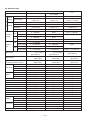
6-2. Model DV 14DL
HITACHI
Maker
DV 14DMR
6 mm (1/4")
6 mm (1/4")
6 mm (1/4")
8 mm dia. x 75 mm
(# 20 x 3")
8 mm dia. x 75 mm
(# 20 x 3")
6.8 mm dia. x 50 mm
(17/64" x 1-31/32")
Brick
14 mm (9/16")
14 mm (9/16")
13 mm (1/2")
Mild steel
13 mm (1/2")
13 mm (1/2")
13 mm (1/2")
Aluminum
13 mm (1/2")
13 mm (1/2")
13 mm (1/2")
Soft wood
45 mm (1-49/64")
45 mm (1-49/64")
27 mm (1-1/16")
Save mode
0 --- 200/min.
None
Low: 0 --- 400/min.
Power mode
0 --- 400/min.
0 --- 400/min.
None
Save mode
0 --- 850/min.
None
Power mode
0 --- 1,750/min.
0 --- 1,750/min.
High: 0 --- 1,400/min.
Save mode
0 --- 2,400/min.
None
Low: 0 --- 6,000/min.
Power mode
0 --- 4,800/min.
0 --- 4,800/min.
None
Save mode
0 --- 10,200/min.
None
Power mode
0 --- 21,000/min.
0 --- 21,000/min.
High: 0 --- 21,000/min.
1.5 --- 7.0 N•m (15 --- 70 kgf•cm)
(13 --- 61 in-lbs.)
1.5 --- 7.0 N•m (15 --- 70 kgf•cm)
(13 --- 61 in-lbs.)
[22 positions]
[22 positions]
52 N•m (530 kgf•cm)
(460 in-lbs.)
Not indicated
[16 positions]
25 N•m (255 kgf•cm)
(221 in-lbs.)
75 N•m (764 kgf•cm)
(664 in-lbs.)
Single sleeve
13 mm (1/2")
Metal
Equipped
Variable speed
Equipped
Equipped
75 N•m (764 kgf•cm)
(664 in-lbs.)
41 N•m (713 kgf•cm)
(620 in-lbs.)
Single sleeve
13 mm (1/2")
Metal
Equipped
Variable speed
Equipped
Equipped
Equipped
Push-button
Equipped
Equipped
T-type
Equipped
Equipped
Equipped
Equipped
3.0 Ah
14.4 V
45 min.
250 mm (9-27/32")
246 mm (9-11/16")
78 mm (3-5/64")
2.1 kg (4.6 lbs.)
Equipped
Push-button
Equipped
Equipped
T-type
Equipped
Equipped
Equipped
Equipped
2.0/2.6/3.0 Ah
14.4 V
50/60/70 min.
253 mm (9-61/64")
245 mm (9-41/64")
76 mm (3")
2.5 kg (5.5 lbs.)
Single sleeve
13 mm (1/2")
Plastic
Equipped
Variable speed
Equipped
Equipped
Equipped
Push-button
Equipped
Equipped
T-type
Equipped
Equipped
Equipped
Equipped
3.0 Ah
14.4 V
45 min.
204 mm (8-1/32")
242 mm (9-17/32")
79 mm (3-7/64")
1.7 kg (3.8 lbs.)
Max. capacity
Machine screw
Screw
driving
Drilling
Rotation
speed
Wood screw
Low
High
Impact
rate
C-2
DV 14DL
Model
Low
High
Slip torque
Max. torque
Max. torque (hard)
(actually measured value)
Type
Capacity
Drill chuck
Outer material
Locking device
Type
Feedback circuit
Switch
Electric brake
Automatic spindle lock
Reversing switch
Replaceable carbon brushes
Replaceable armature
Handle shape
Soft-grip handle
Side handle
Belt hook
Strap
Nominal capacity
Battery
Nominal voltage
Charging time*
Overall length
Dimensions Overall height
Overall width
Weight
52 N•m (530 kgf•cm)
(460 in-lbs.)
*: Charging time varies depending on the type of charger to be used.
--- 10 ---
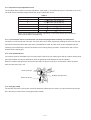
7. WORKING PERFORMANCE PER SINGLE CHARGE
7-1. Model DV 18DL
Drilling and fastening performance comparison per charge
Type of work
Maker
Model name
0
0
100
*600
Working capacity (*)
200
300
*1200
*1800
400
*2400
Driling
speed
(sec./pc.)
DV 18DL
130
5.5
DV 18DMR
130
5.5
HITACHI
120
C -- 1
6.0
< High speed >
DV 18DL
130
3.7
DV 18DMR
130
3.7
140
3.5
HITACHI
C -- 1
< Low speed >
DV 18DL
180
4.4
DV 18DMR
180
4.4
205
3.5
HITACHI
C -- 1
< High speed >
DV 18DL
50
7.0
DV 18DMR
50
7.0
55
6.5
HITACHI
C -- 1
< Low speed >
DV 18DL
*1370
0.4
DV 18DMR
*1370
0.4
HITACHI
*1510
C -- 1
0.5
*: Number of holes or fasteners per charge
The above table shows an example of test data. The batteries used in this test are as follows:
Model DV 18DL, DV 18DMR and C-1: 3.0 Ah
As actually measured values listed in the above table may vary depending on the sharpness of the drill bit, workpiece
hardness (particularly in wood materials), moisture content of wood, charging condition, operator skill, etc.
This data should be used as a comparative guide only.
--- 11 ---
7-2. Model DV 14DL
Drilling and fastening performance comparison per charge
Working capacity (*)
Type of work
Maker
Model name
0
0
100
*600
200
*1200
300
*1800
400
*2400
Driling
speed
(sec./pc.)
DV 14DL
100
6.2
DV 14DMR
100
6.2
HITACHI
120
C -- 2
6.0
< High speed >
DV 14DL
90
4.6
DV 14DMR
90
4.6
HITACHI
140
3.5
DV 14DL
150
5.3
DV 14DMR
150
5.3
C -- 2
< Low speed >
HITACHI
205
C -- 2
3.5
< High speed >
DV 14DL
70
5.4
DV 14DMR
70
5.4
HITACHI
C -- 2
55
6.5
< Low speed >
DV 14DL
*1350
0.4
DV 14DMR
*1350
0.4
HITACHI
*1140
C -- 2
0.5
*: Number of holes or fasteners per charge
The above table shows an example of test data. The batteries used in this test are as follows:
Model DV 14DL, DV 14DMR and C-2: 3.0 Ah
As actually measured values listed in the above table may vary depending on the sharpness of the drill bit, workpiece
hardness (particularly in wood materials), moisture content of wood, charging condition, operator skill, etc.
This data should be used as a comparative guide only.
--- 12 ---
8. PRECAUTIONS IN SALES PROMOTION
8-1. Safety Instructions
In the interest of promoting the safest and most efficient use of the Models DV 18DL and DV 14DL Cordless
Impact Driver Drills by all of our customers, it is very important that at the time of sale, the salesperson carefully
ensures that the buyer seriously recognizes the importance of the contents of the Handling Instructions, and fully
understands the meaning of the precautions listed on the Caution Plate and the Name Plate attached to each tool.
A. Handling instructions
Salespersons must be thoroughly familiar with the contents of the Handling Instructions in order to give pertinent
advice to the customer. In particular, they must have a thorough understanding of the precautions for use of the
cordless tools which are different from those of ordinary electric power tools.
(1) Before use, ensure that the unit is fully charged.
New units are not fully charged. Even if the units were fully charged at the factory, long periods of inactivity,
such as during shipping, cause the storage battery to lose its charge. Customers must be instructed to fully
charge the unit prior to use.
(2) Connect the charge to an AC power outlet only.
Use of any other power source (DC outlet, fuel powered generator, etc.) will cause the charger to overheat and
burn out.
(3) Do not use any voltage increasing equipment (transformer etc.) between the power source and the charger. If
the charger is used with voltage higher than that indicated on the unit, it will not function properly.
(4) Conduct battery charging at an ambient temperature range of 0ûC --- 40ûC (32ûF --- 104ûF).
Special temperature sensitive devices are employed in the charger to permit rapid charging. Ensure that
customers are instructed to use the charger at the indicated ambient temperature range. At temperature under
0ûC (32ûF), the thermostat will not function properly, and the storage battery may be overcharged. At
temperature over 40ûC (104ûF), the storage battery cannot be sufficiently charged. The optimum temperature
range is 20ûC --- 25ûC (68ûF --- 77ûF).
(5) The battery charger should not be used continuously.
At high ambient temperature, if over three storage batteries are charged in succession, the temperature of the
coils on the transformer will rise and there is a chance that the temperature fuse inserted in the interior of the
transformer will inadvertently melt. After charging one battery, please wait about 15 minutes before charging
the next battery.
(6) Do not insert foreign objects into the air vents on the charger
The charger case is equipped with air vents to protect the internal electronic components from overheating.
Caution the customer not to allow foreign materials, such as metallic or flammable objects, to be dropped or
inserted into the air vents. This could cause electrical shock, fire or other serious hazards.
--- 13 ---
(7) Do not attempt to disassemble the storage battery or the charger.
Special devices, such as a thermostat, are built into the storage battery and the charger to permit rapid
charging. Incorrect parts replacement and/or wiring will cause malfunctions which could result in fire or other
hazards. Instruct the customer to bring these units to an authorized service center in the event repair or
replacement is necessary.
(8) Disposal of the storage batteries
Ensure that all customers understand that the storage batteries should be returned to the Hitachi power tool
sales outlet or the authorized service center when they are no longer capable of being recharged or repaired.
If thrown into a fire, the batteries may explode, or, if discarded indiscriminately, leakage of the cadmium
compound contained in the battery may cause environmental pollution.
B. Caution plates
(1) The following cautions are listed on the name plate attached to the main body of each tool.
For the U.S.A. and Canada
Warning
To reduce the risk of injury, user must read and understand
Instruction Manual.
AVERTISSEMENT
Afin de reduire le risque de blessures, l'utilisateur doit lire
et bien comprendre le mode d'emploi.
(2) The following cautions are listed on the name plate attached to each storage battery.
For Europe
CAUTION
For safe operation, see instruction manual.
Use HITACHI charger recommended in insturction manual
for recharging.
For the U.S.A. and Canada
CAUTION
Read thoroughly HANDLING INSTRUCTIONS before use.
Do not disassemble nor throw into fire.
(3) The following cautions are listed on the name plate to the Model UC 18YRL charger.
CAUTION
For safe operation, see instruction manual.
Charge HITACHI rechargeable batteries types EB7, EB9,
EB12, EB14, EB18, EBL14, EBM18 series. Other types of
batteries may burst causing personal injury and damage.
Charge between 32û F and 104û F. Rest 15 minutes between
the charging of batteries.
Indoor use only.
Replace defective cord immediately.
--- 14 ---
8-2. Inherent Drawbacks of Cordless Impact Driver Drills Requiring Particular Attention During Sales
Promotion
The cordless impact driver drill offers many advantages; it can be used in places where no power source is
available, the absence of a cord allows easy use etc. However, any cordless tool has certain inherent drawbacks.
Salespersons must be thoroughly familiar with these drawbacks in order to properly advise the customer in the
most efficient use of the tool.
A. Suggestions and precautions for the efficient use of the tool
(1) Use the cordless impact driver drill for comparatively light work.
Because they are battery driven, the output of the motor in cordless driver drills is rather low in comparison
with conventional electric power tools. Accordingly, they are not suitable for continuous drilling of many holes
in succession, or for drilling into particularly hard materials which creates a heavy load. Sales persons should
recommend conventional electric power tools for such heavy work.
(2) Drilling of large diameter holes should be conducted at low speed.
Instruct the customer that drilling of large diameter holes or other work which requires particularly strong
torque should be done at low speed. Because there is less torque at high speed, attempting such work at high
speed will not improve working efficiency.
(3) Do not insert a foreign object into body vent holes.
The body of this tool has vent holes for improving the cooling efficiency. As a fan is built into the motor, a
foreign object inserted through a vent hole may cause a failure. Please instruct customers to never insert a
foreign object into the vent hole.
(4) Use at the thrust of 100 to 150 N (10 to 15 kgf, 22 to 33 lbs.)
The drilling speed of this unit is not accelerated even if the tool is strongly pressed against the workpiece as is
done with a usual AC impact drill. Such operation will damage the drill bit, resulting in not only poor working
efficiency but also burnout of the motor.
(5) Avoid "Locking" of the motor.
Locking of the motor will cause an overload current that could result in burning of the motor and/or rapid
deterioration of the battery. Salespersons should advise the customer to immediately release the switch and
stop operation if the motor becomes locked. (A jammed drill bit can be disengaged from the workpiece
material by setting the switch to reverse rotation, or by manually turning the main body of the tool.)
(6) Variation in amount of work possible per charge
Although the nominal chargeable capacity of the storage batteries used with the Models DV 18DL and
DV 14DL is 2.0 Ah, 2.6 Ah or 3.0 Ah, the actual capacity may vary within 10% of that value depending on the
ambient temperature during use and charging, and the number of times the batteries have been recharged. It
should be noted that other factors which may have a bearing on the amount of work possible per charge are
the working conditions (ambient temperature, type and moisture content of the workpiece, sharpness of the
drill bit, etc.) and the operational skill of the user.
--- 15 ---
(7) Precautions in the use of HSS drill bits
For example, although the Model DV 18DL is designed for drilling capacities of 50 mm (2") in wood, and
13 mm (1/2") in aluminum and mild steel, this capability is not as efficient as conventional electric power tools.
In particular, when drilling through aluminum material with a 13 mm (1/2") drill bit, the drill tends to become
locked when the drill bit penetrates through the material. For this reason, the customer should be cautioned to
reduce the thrust on the main body of the drill when drilling completely through the material to avoid locking
the tool. Repeated locking of the drill causes excessive current flow from the batteries which not only
decreases the amount of work possible per charge, but could also result in burning of the motor.
(8) Securely tighten the sleeve of the keyless chuck.
The keyless chuck may slip during operation if the shape of the drill bit shank is cylindrical depending on the
surface conditions, materials, etc. Please instruct the customers to retighten the keyless chuck more securely
if the keyless chuck slips during operation. The holding force of the keyless chuck is increased as the
tightening force of the keyless chuck is increased. The Models DV 18DL and DV 14DL are equipped with the
locking device to prevent loosening of the keyless chuck. The sleeve makes noise when tightening or
loosening. This is because of the locking device and there is no problem.
(9) Avoid continuous use.
Although the Model DV 18DL can bear continuous operation under certain conditions, operating conditions are
different depending on material of workpiece and sharpness of the drill bit in use. Please instruct the
customers to avoid continuous use of the Models DV 18DVL and DV 14DL and take a pause about 15 minutes
after a single charge operation as a guide.
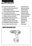
9. REFERENCE MATERIALS
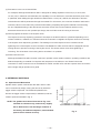
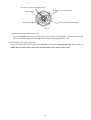
9-1. Speed Control Mechanism
Spindle rotation speed of the Models DV 18DL and DV 14DL
trigger switch is depresed. The relationship between the
amount the trigger switch is depressed (in millimeters) and the
rotation speed is illustrated in Fig. 2.
Rotation speed
can be controlled by simply varying the amount by which the
NOTE: The gradient and values illustrated in Fig. 2 are
intended for reference only, and will vary slightly
Depressed amount of the trigger switch (mm)
due to differences in the discharge condition of
the battery, the ambient temprature, and individual
speed-control element accuracy.
--- 16 ---
Fig. 2
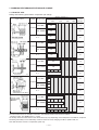
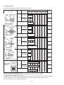
10. REPAIR GUIDE
Be sure to remove the storage batteries from the main body before servicing. Inadvertent triggering of the switch
with the storage battery connected will result in danger of accidental turning of the motor.
10-1. Precautions in Disassembly and Reassembly
The [Bold] numbers in the descriptions below correspond to the item numbers in the Parts List and the exploded
assembly diagram for the Model DV 18DL, and the <Bold> numbers to those in the Parts List and the exploded
assembly diagram for the Model DV 14DL.
10-1-1. Disassembly
(1) Removal of the Hook Ass'y [53] <53> or the Hook Ass'y (W/Light) [55] <59>
Remove Special Screw (A) M5 [59] [57] with a flat-blade screwdriver or a coin. Remove the Hook Ass'y [53]
<53> or the Hook Ass'y (W/Light) [55] <59> and the Hook Spring [58] <56>.
(2) Removal of the Carbon Brushes 5 x 6 x 11.5 [34] <34>
Remove the Brush Cap [35] <35> first then pry the Carbon Brush 5 x 6 x 11.5 [34] <34> off with a flat-blade
screwdriver (at the position of collars). Remove the Brush Caps [35] <35> and the Carbon Brushes
5 x 6 x 11.5 [34] <34> at both sides.
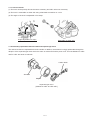
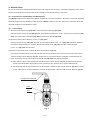
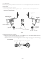
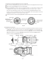
(3) Removal of the Drill Chuck 13VLRL-N (W/O Chuck Wrench) [2] <2>
Perform the following steps (a) and (b) with the main unit mounted in the vise for removal of the Drill Chuck
13VLRL-N (W/O Chuck Wrench) [2] <2>. At this time, it is recommended to sandwich a cloth between the
main unit and the vise to prevent Housing (A).(B) Set [38] <38> from being scratched.
(a) Fully open the jaws of the Drill Chuck 13VLRL-N (W/O Chuck Wrench) [2] <2> and remove the Special
Screw (Left Hand) M6 x 23 [1] <1> by turning clockwise (be careful that it is a left-handed screw).
(b) Fix the hexagonal bar wrench M10 into the Drill Chuck 13VLRL-N (W/O Chuck Wrench) [2] <2> as shown
in Fig. 3 then turn it counterclockwise to remove the Drill Chuck 13VLRL-N (W/O Chuck Wrench) [2] <2>.
Hexagonal bar wrench
Cloth
Vise
Fig. 3
--- 17 ---
(4) Adjust the Front Cap [4] <4> to "
".
(5) Disassembly of the main unit
Remove the ten Tapping Screws (W/Flange) D3 x 16 (Black) [36] <36> from the main unit. Holding the battery
chamber of Housing (B) [38] <38>, gently remove Housing (B) [38] <38>. Then the inside parts can be
removed in an assembled or single state. All the parts can be easily removed by raising the Front Cap [4]
<4>. Parts are separated into the drive unit (an assembly of the armature and the gear unit), power supply
unit, Pushing Button [45] <46> and Strap (Black) [57] <55>.
(6) Disassembly of the drive unit
(a) Remove the Front Cap [4] <4> and the Click Spring [12] <12> from the Front Case [11] <11>.
NOTE: Do not remove the Nut [6] <6> from the Front Case [11] <11> in this step.
(b) Remove the Shift Arm [21] <21> from the Gear Box Ass'y [3] <3> and remove the Shift Knob [41] <41>
from the Shift Arm [21] <21>. Do not deform the Shift Arm [21] <21> by applying excessive force.
(c) Turn the Motor Spacer [30] <30> until a click is heard counterclockwise viewing from the rear of the
Armature and Pinion Set [31] <31>. Remove the Motor Spacer [30] <30> from the Rear Case [20] <20>.
Thus the armature unit is separated from the gear unit.
(7) Disassembly of the armature unit
(a) Removal of the Magnet [32] <32>
Note that the magnetic force of the Magnet [32] <32> is strong. Hold the Motor Spacer [30] <30> securely
and pull toward the back of the Armature and Pinion Set [31] <31> to remove.
NOTE: Be careful that the ball bearing and the washer behind the Armature and Pinion Set [31]
<31> may be attracted to the Magnet [32] <32> and come off the Armature and Pinion Set
[31] <31> when removing the Magnet [32] <32>.
(b) Removal of the Motor Spacer [30] <30>
Remove the Motor Spacer [30] <30> from the Armature and Pinion Set [31] <31>. If it is too hard to
remove, support the Motor Spacer [30] <30> and press down the tip of the armature shaft of the Armature
and Pinion Set [31] <31> with a hand press.
(8) Disassembly of the gear unit
(a) Disassembly of the deceleration mechanism
Turn Washer (B) [29] <29> mounted in the Rear Case [20] <20> counterclockwise to remove. Take out the
First Ring Gear [28] <28>, Planet Gear (A) Set (4 pcs.) [27] <27>, Pinion (B) [26] <26>, Planet Gear (B)
Set (4 pcs.) [25] <25>, Pinion (C) [24] <24> and Slide Ring Gear [23] <23> in order. Then remove the
Screw Set M3 x 12 (4 pcs.) [22] <22> that connects the Front Case [11] <11> with the Rear Case [20]
<20>. Take out Washer (D) [19] <19>, Planet Gear (C) Set (5 pcs.) [18] <18>, Carrier [17] <17>, Ring
Gear [16] <16>, Pin Set (6 pcs.) [13] <13>, Lock Ring [15] <15> and Washer (A) [14] <14> from the Front
Case [11] <11> in order.
NOTE: Do not lose small parts. Pay special attention to the Pin Set (6 pcs.) [13] <13>, because they
are apt to roll.
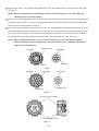
(b) Removal of the Switch Plate [5] <5>
Turn the switch flange so as to fit the projection of the switch flange to the recess of the Switch Plate [5]
<5>, then remove the Switch Plate [5] <5> from the Front Case [11] <11>. (See Fig. 4.)
--- 18 ---
Projections of Front Case [11] <11>
Projections of switch flange
Switch flange
Switch Plate [5] <5>
Recess of Switch Plate [5] <5>
Fig. 4
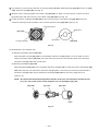
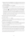
(c) Disassembly of the clutch mechanism
Turn the Nut [6] <6> counterclockwise to remove from the Front Case [11] <11>. Take out the Spring [7]
<7>, Thrust Washer [8] <8>, Stopper [9] <9> and Stopper Spring [10] <10> in order.
(9) Disassembly of the power supply unit
Disconnect each internal wire of Brush Block [33] <33> and Terminals [50] [52] <50> <52> with a solder iron.
NOTE: Do not remove the fin secured to the DC-speed control switch with a screw.
--- 19 ---
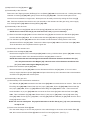
10-1-2. Reassembly
Reassembly can generally be carried out as the reverse of the disassembly procedure, with some items to be
noted as follows.
(1) Reassembly of the power supply unit
Perform wiring according to the wiring diagram (Fig. 5). Pay attention to the connecting direction of the
internal wires and the terminals.
[33] <33>
[44] <44>
Internal wire (red)
[46] <47>
Internal wire (black)
[52] <52>
[50] <50>
[51] <51>
Internal wire (brown)
Internal wire (blue)
[49] <49> [48] <48>
Fig. 5
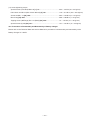
(2) Reassembly of the clutch mechanism
(a) Mount the Stopper Spring [10] <10> (2 pcs.), Stopper [9] <9> (2 pcs.), Thrust Washer [8] <8> and Spring
[7] <7> to the Front Case [11] <11> in order (see Fig. 6).
NOTE: Be careful not to drop the Stopper [9] <9> and the Stopper Spring [10] <10> until the Nut [6]
<6> is inserted.
[7] <7> [8] <8> [9] <9> [10] <10> [11] <11>
Fig. 6
--- 20 ---
(b) Screw the Nut [6] <6> in the Front Case [11] <11> (see Fig. 7).
Align the mark (i) on the Nut [6] <6> with the mark on the Front Case [11] <11> then screw it in. Rotate the
Nut [6] <6> about a turn clockwise to align the mark (i) on the Nut [6] <6> with the mark on the Front Case
[11] <11>. At this time, check that the "Y" surface of the Nut [6] <6> is almost flush with the "Z" surface of
the Front Case [11] <11>. After above step, tighten the Nut [6] <6> so that the Nut [6] <6> pushes the
Stopper [9] <9> into the Front Case [11] <11>.
Mark
Mark
Mark (i)
Mark
Mark (i)
Mark (i)
Y surface
[6] <6>
Z surface
[9] <9>
[10] <10>
Z surface
Y surface
[8] <8> [10] <10>
[6] <6>
[9] <9>
[7] <7>
[8] <8> [10] <10>
[6] <6>
[7] <7>
[8] <8>
[11] <11>
[11] <11>
[11] <11>
[7] <7>
[9] <9>
Fig. 7
(3) Reassembly of the gear unit
(a) Apply grease (Hitachi Motor Grease No. 29) to the engaging portions of each gear and contacting surfaces
with the pin set (6 pcs.) of the ring gear properly.
(b) Mount the parts from the Pin Set (6 pcs.) [13] <13> to Washer (B) [29] <29> to the part assembled in the
above (2) in order (see Fig. 8).
[12] [13] [14] [15] [16] [17] [18] [19] [20]
<12> <13> <14> <15> <16> <17> <18> <19> <20>
[26] [27] [28] [29]
<26> <27> <28> <29>
Fig. 8
--- 21 ---
[22] [23] [24] [25]
<22> <23> <24> <25>
1
Apply grease approx. 1.2 g (Hitachi Motor Grease No. 29) to the shaded portion in the Front Case [11] <11>
(See Fig. 9).
NOTE: Be sure to apply grease to the shaded portion in the Front Case [11] <11>. Otherwise, the
spindle lock may not work properly.
2
Mount the Lock Ring [15] <15> to the Front Case [11] <11> so that the projections on the Lock Ring [15] <15>
engage with the recesses in the Front Case [11] <11>. Make sure that the flat plane of Lock Ring [15] <15>
faces the Front Case [11] <11> (see Fig. 9).
3
Mount the Carrier [17] <17> so that recess (A) on the Lock Ring [15] <15> is aligned with projection (B) on the
Carrier [17] <17> (be careful of the direction). Then make sure that the flat plane of the spindle faces the flat
plane of the Carrier [17] <17>. If mounted in wrong direction, the flat plane of the spindle may be stopped at
the position about 2 mm lower than the flat plane of the Carrier [17] <17> (see Figs. 10 and 11).
NOTE: When mounting the Carrier [17] <17> to the Lock Ring [15] <15>, never apply the grease
between the plates of the Lock Ring [15] <15> and Carrier [17] <17>. Otherwise, the spindle
lock may not work properly.
[11] <11>
Shaded portion
[15] <15>
Projection
Recess
Fig. 9
[11] <11>
[15] <15>
[17] <17>
Projection (B)
Recess(A)
Fig. 10
Flat plane of the spindle
Flat plane of the carrier
Fig. 11
--- 22 ---
4
Pay attention to the mounting direction of the Ring Gear [16] <16>, Slide Ring Gear [23] <23>, Pinion (C) [24]
<24> and Pinion (B) [26] <26> (see Fig. 8).
Mount the Front Case [11] <11> to the Rear Case [20] <20> so that the concave portion of the Front Case
[11] <11> aligns with the protrusion of the Rear Case [20] <20> (see Fig. 15).
6
Fit the protrusion of Washer (B) [29] <29> in the concave portion of the Rear Case [20] <20> and turn it
clockwise viewing from the armature until it contacts the Rear Case [20] <20> (see Fig. 12).
Concave portion
Protrusion
[20] <20>
Protrusion
Concave portion
[29] <29>
Fig. 12
(4) Reassembly of the armature unit
(a) Mounting the Motor Spacer [30] <30>
Mount the Motor Spacer [30] <30> to the Armature and Pinion Set [31] <31>. If it is too hard to mount,
support the Motor Spacer [30] <30> and press down the rear end of the armature shaft of the Armature
and Pinion Set [31] <31> with a hand press.
(b) Mounting the Magnet [32] <32>
Mount the Magnet [32] <32> to the Armature and Pinion Set [31] <31> so that the notch of the Magnet [32]
<32> faces the rear of the Armature and Pinion Set [31] <31>. Hold each part securely as the Armature
and Pinion Set [31] <31> may be attracted to the Magnet [32] <32> by the strong magnetic force
(see Fig. 13).
NOTE: Be careful that the ball bearing and the washer at the rear of the Armature and Pinion Set
[31] <31> may come off due to the magnetic force of the Magnet [32] <32>.
[30] <30>
[31] <31>
[32] <32>
Notch
Fig. 13
--- 23 ---
(5) Reassembly of the drive unit
(a) Fit the protrusion of the Motor Spacer [30] <30> in the concave portion of the Rear Case [20] <20>
engaging the pinion of the Armature and Pinion Set [31] <31> with Planet Gear (A) Set (4 pcs.) [27] <27>.
Turn it fully clockwise viewing from the rear of the Armature and Pinion Set [31] <31> (see Fig. 14).
[20] <20>
[30] <30>
Concave portion
Protrusion
Protrusion
Concave portion
[29] <29>
Fig. 14
(b) Mounting the Shift Arm [21] <21> and the Shift Knob [41] <41> (see Fig. 15).
1
Mount the Shift Arm [21] <21> to the protruded side of the Rear Case [20] <20>. At this time, insert the
protrusion of the Shift Arm [21] <21> into the hole of the Rear Case [20] <20> and check that the
protrusion is inserted into the groove of the Slide Ring Gear [23] <23> that is mounted in the Rear Case
[20] <20> (see Fig. 8).
2
Insert the Shift Arm [21] <21> into the groove of the Shift Knob [41] <41> facing "LOW" indication on the
Shift Knob [41] <41> backward.
Top view
[21] <21> Protrusion
Concave portion
Side view
Indication "LOW"
[41] <41>
Groove portion of slide ring gear
Fig. 15
--- 24 ---
(c) Mounting the Click Spring [12] <12> and the Front Cap [4] <4>.
1
Mount the Switch Plate [5] <5> aligning with the projections of the Front Case [11] <11> as shown in Fig. 4.
2
Mount the Click Spring [12] <12> to the Front Case [11] <11>.
3
When the Nut [6] <6> is screwed in the Front Case [11] <11> about 1-11/12 turns (690û), the mark (i) of the
Nut [6] <6> and the marking of the Switch Plate [5] <5> are positioned as shown in Fig. 16. Set the
narrow slit of the switch flange as shown in Fig. 16. Mount the Front Cap [4] <4> aligning the narrow
projection of the Front Cap [4] <4> with the mark (i) of the Nut [6] <6>. (The narrow projection of the Front
Cap [4] <4> is positioned at "1" when viewed from the outside.)
Check that the protrusion of the Click Spring [12] <12> is inserted into the groove inside the Front Cap [4]
<4>.
Switch flange
Marking of the
Switch Plate [5] <5>
Narrow slit of
the switch flange
Mark (i)
Wide slit of the
switch flange
Narrow projection
of the Front Cap
[4] <4>
Switch Plate [5] <5>
"1"
Fig. 16
(6) Reassembly of the main unit
(a) Mount the power supply unit and the drive unit that were reassembled in the above procedure to Housing
(A) [38] <38>. At this time, align the protrusions of the Brush Block [33] <33>, Front Case [11] <11> and
Motor Spacer [30] <30> with the concave portions of Housing (A) [38] <38>, the notch of the Magnet [32]
<32> with the protrusion of Housing (A) [38] <38>, and the groove of the Front Cap [4] <4> with the
protrusion of Housing (A) [38] <38> (see Fig. 17).
Protrusion
[33] <33>
[32] <32>
Notch
Concave portion
[30] <30>
Protrusion
Protrusion [11] <11>
Protrusion
Groove
Concave portion Concave portion
Concave portion
[38] <38>
Protrusion
Protrusion
Fig. 17
--- 25 ---
[4] <4>
(b) Mount the DC-Speed Control Switch [46] <47> that was not mounted in the above step (a) to Housing (A)
[38] <38>. Mount the Pushing Button [45] <46> to Housing (A) [38] <38>. Check that the protrusion of the
forward/reverse changeover lever of the DC-Speed Control Switch [46] <47> is inserted into the groove of
the Pushing Button [45] <46>.
(c) Mount the Strap (Black) [57] <55> to Housing (A) [38] <38>.
(d) Align Housing (A) [38] <38> with Housing (B) [38] <38> and secure with ten Tapping Screws (W/Flange)
D3 x 16 (Black) [36] <36>.
(e) Check for proper operation of the Front Cap [4] <4> and the Shift Knob [41] <41>. When the reassembly
procedure is completed up to step (e), ensure that every indication on the Front Cap [4] <4> from number
"1" to the hammer mark "
" can be aligned with the triangle mark on Housing (A). (B) Set [38] <38>
respectively and that the Front Cap [4] <4> turns moderately. If any indication on the Front Cap [4] <4>
cannot be aligned with the triangle mark on Housing (A). (B) Set [38] <38>, correctly remount the Front
Cap [4] <4> according to step (2) or (5) (c) as it is improperly mounted. Check for proper operation of the
Shift Knob [41] <41>. Check that the speed changes between high and low properly by shifting the Shift
Knob [41] <41>. If the speed cannot change properly or moderately, correctly remount the Shift Knob [41]
<41> according to step (3) (b) or (5) (b) as it is improperly mounted.
(7) Mounting the Drill Chuck 13VLRL-N (W/O Chuck Wrench) [2] <2>
Mount the Drill Chuck 13VLRL-N (W/O Chuck Wrench) [2] <2> to the spindle and tighten the Special Screw
(Left Hand) M6 x 23 [1] <1>.
(8) Mounting the Carbon Brushes 5 x 6 x 11.5 [34] <34>
Mount the two Carbon Brushes 5 x 6 x 11.5 [34] <34> to the Brush Block [33] <33> and secure the two Brush
Caps [35] <35> to the Brush Block [33] <33>. Check that the claws of the Carbon Brushes 5 x 6 x 11.5 [34]
<34> are properly inserted into the brush tubes.
(9) Reassembly of the Hook Ass'y [53] <53> or the Hook Ass'y (W/Light) [55] <59>
Check that the V-Lock Nut M5 [54] <54> is mounted to the Hook Ass'y [53] <53> or the Hook Ass'y (W/Light)
[55] <59>. Mount the Hook Spring [58] <56> and secure it with Special Screw (A) M5 [59] <57>. Make sure
to mount the Hook Spring [58] <56> with its larger diameter side pointing inward the housing.
(10) Other precautions in reassembling
After completion of reassembly, check that the rotating direction of the Drill Chuck 13VLRL-N (W/O Chuck
Wrench) [2] <2> matches the position of the Pushing Button [45] <46>. When the Pushing Button [45] <46>
is pressed from the (R) side, the rotating direction of the Drill Chuck 13VLRL-N (W/O Chuck Wrench) [2] <2>
should be clockwise as viewed from behind. Switch on and off the Models DV 18DL or DV 14DL using the
battery. Then turn the Drill Chuck 13VLRL-N (W/O Chuck Wrench) [2] <2> by hand in forward and reverse
direction to check that the spindle lock properly works in either direction within a half rotation. Check that the
runout of the Drill Chuck 13VLRL-N (W/O Chuck Wrench) [2] <2> is 0.8 mm or less at the position 110 mm
away from the tip of the chuck using a 12-mm dia. test bar.
--- 26 ---
(11) Screw tightening torque
Special Screw (Left Hand) M6 x 23 [1] <1> ............................................. 3.92 --- 4.9 N•m (40 --- 50 kgf•cm)
Drill Chuck 13VLRL-N (W/O Chuck Wrench) [2] <2> ............................... 17.6 --- 21.6 N•m (180 --- 220 kgf•cm)
Screw Set M3 x 12 [22] <22> ................................................................... 0.62 --- 0.94 N•m (6 --- 10 kgf•cm)
Brush Cap [35] <35> ................................................................................ 0.68 --- 0.88 N•m (7 --- 9 kgf•cm)
Tapping Screw (W/Flange) D3 x 16 (Black) [36] <36> ............................. 1.0 --- 1.6 N•m (10 --- 16 kgf•cm)
Special Screw (A) M5 [59] <57> .............................................................. 1.47 --- 2.45 N•m (15 --- 25 kgf•cm)
10-2. Precaution in Disassembly and Reassembly of Battery Charger
Please refer to the Technical Data and Service Manual for precautions in disassembly and reassembly of the
Battery Charger UC 18YRL.
--- 27 ---
11. STANDARD REPAIR TIME (UNIT) SCHEDULES
MODEL
Variable
Fixed
10
20
30
Work Flow
DV 18DL
DV 14DL
Housing (A).(B)
Set
General Assembly
Armature and
Pinion Set
Magnet
Brush Block
DC-Speed
Control Switch
Shift Knob
Gear Box Ass'y Front Cap
Nut
Drill Chuck
Spring
(Keyless)
Front Case
Lock Ring
Ring Gear
Hook Ass'y
Carrier
Planet Gear
(C) Set
Rear Case
Shift Arm
Slide Ring Gear
Pinion (C)
Planet Gear
(B) Set
Pinion (B)
Planet Gear
(A) Set
First Ring Gear
--- 28 ---
40
50
60
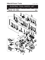
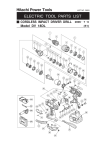
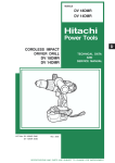
Hitachi Power Tools
LIST NO. G853
ELECTRIC TOOL PARTS LIST
CORDLESS IMPACT DRIVER DRILL
Model DV 18DL
2006
•
7•6
(E1)
1
2
3
9
4
10
12
5
11
6
7
13
14
8
15
16
17
26
18
27
21
19
20
28
29
30
22
23
24
31
25
32
33
34
35
36
37
38
44
43
45
42
41
46
501
59
58
40
502
61
39
48
503
49
52
51
50
49
48
47
504
56
53
54
57
55
54
60
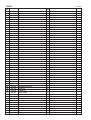
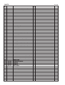
PARTS
ITEM
NO.
1
DV 18DL
CODE NO.
NO.
USED
DESCRIPTION
311-959
SPECIAL SCREW (LEFT HAND) M6X23
1
2
323-898
DRILL CHUCK 13VLRL-N (W/O CHUCK WRENCH)
1
3
324-061
GEAR BOX ASS’Y
1
4
324-074
FRONT CAP
1
5
324-136
SWITCH PLATE
1
6
324-064
NUT
1
7
324-135
SPRING
1
8
324-063
THRUST WASHER
1
9
322-972
STOPPER
2
10
322-971
STOPPER SPRING
2
11
324-062
FRONT CASE
1
12
320-773
CLICK SPRING
1
13
322-975
PIN SET (6 PCS.)
6
14
322-980
WASHER (A)
1
15
322-976
LOCK RING
1
16
324-066
RING GEAR
1
17
322-978
CARRIER
1
18
324-067
PLANET GEAR (C) SET (5 PCS.)
5
19
324-065
WASHER (D)
1
20
322-981
REAR CASE
1
21
322-990
SHIFT ARM
1
22
320-087
SCREW SET M3X12 (4 PCS.)
4
23
324-069
SLIDE RING GEAR
1
24
324-068
PINION (C)
1
25
324-070
PLANET GEAR (B) SET (4 PCS.)
4
26
324-071
PINION (B)
1
27
324-073
PLANET GEAR (A) SET (4 PCS.)
4
28
324-072
FIRST RING GEAR
1
29
322-988
WASHER (B)
1
30
322-989
MOTOR SPACER
1
31
360-701
ARMATURE AND PINION SET
1
32
322-996
MAGNET
1
33
322-993
BRUSH BLOCK
1
34
999-054
CARBON BRUSH 5X6X11.5 (1 PAIR)
2
35
319-918
BRUSH CAP
2
36
313-687
TAPPING SCREW (W/FLANGE) D3X16 (BLACK)
NAME PLATE
1
326-278
HOUSING (A).(B) SET
1
37
38
REMARKS
INCLUD. 4-11, 13-30
10
39
326-279
PLATE (A)
1
40
326-276
LEVER (A)
1
41
324-137
SHIFT KNOB
1
42
326-277
LEVER (B)
1
*
43
326-493
SUPPORT (D)
1
EXCEPT FOR USA, CAN
*
44
323-229
FERRITE CORE
1
EXCEPT FOR USA, CAN, AUS
45
322-997
PUSHING BUTTON
1
46
322-994
DC-SPEED CONTROL SWITCH
1
HITACHI LABEL
1
47
48
958-715
TAPPING SCREW D4X10
2
49
996-118
HOLDER SPRING
2
50
323-003
TERMINAL
1
51
320-997
TERMINAL PIECE
1
--- 2 ---
* ALTERNATIVE PARTS
7 -- 06
PARTS
ITEM
NO.
52
*
DV 18DL
CODE NO.
322-995
NO.
USED
DESCRIPTION
TERMINAL
REMARKS
1
53
320-287
HOOK ASS’Y
1
54
320-288
V-LOCK NUT M5
1
*
55
321-918
HOOK ASS’Y (W/LIGHT)
1
INCLUD. 54, 56 FOR GBR, FRG, USA, CAN
*
56
321-672
TAPPING SCREW D2X6
2
FOR GBR, FRG, USA, CAN
*
57
306-952
STRAP (BLACK)
1
EXCEPT FOR USA, CAN
58
319-926
HOOK SPRING
1
59
320-881
SPECIAL SCREW (A) M5
1
*
60
326-240
BATTERY EBM 1830 (EUROPE, AUS, NZL)
2
*
60
326-241
BATTERY EBM 1830 (USA, CAN)
2
*
61
CAUTION PLATE
1
7 -- 06
INCLUD. 54 FOR NOR, SWE, DEN, FRG, AUS
FOR USA, CAN
* ALTERNATIVE PARTS
--- 3 ---
STANDARD ACCESSORIES
ITEM
NO.
501
CODE NO.
DV 18DL
NO.
USED
DESCRIPTION
CHARGER (MODEL UC 18YRL)
1
502
983-006
+ DRIVER BIT NO. 2 65L
1
503
323-001
SIDE HANDLE
1
504
323-230
CASE
1
--- 4 ---
* ALTERNATIVE PARTS
REMARKS
Printed in Japan 7-- 06
(060706N)
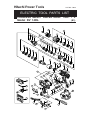
Hitachi Power Tools
LIST NO. G854
ELECTRIC TOOL PARTS LIST
CORDLESS IMPACT DRIVER DRILL
Model DV 14DL
2006
•
7•6
(E1)
1
2
3
9
4
10
12
5
11
6
7
13
14
8
15
16
17
26
18
27
21
19
20
28
29
30
22
23
24
31
25
32
33
35
34
36
37
38
44
43
46
42
41
47
57
501
56
40
502
39
48
49
503
52
51
50
49
48
45
504
60
53
54
55
59
54
58
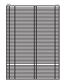
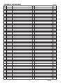
PARTS
ITEM
NO.
1
CODE NO.
DESCRIPTION
311-959
SPECIAL SCREW (LEFT HAND) M6X23
1
2
323-898
DRILL CHUCK 13VLRL-N (W/O CHUCK WRENCH)
1
3
324-061
GEAR BOX ASS’Y
1
4
324-074
FRONT CAP
1
5
324-136
SWITCH PLATE
1
6
324-064
NUT
1
7
324-135
SPRING
1
8
324-063
THRUST WASHER
1
9
322-972
STOPPER
2
10
322-971
STOPPER SPRING
2
11
324-062
FRONT CASE
1
12
323-231
CLICK SPRING
1
13
322-975
PIN SET (6 PCS.)
6
14
322-980
WASHER (A)
1
15
322-976
LOCK RING
1
16
324-066
RING GEAR
1
17
322-978
CARRIER
1
18
324-067
PLANET GEAR (C) SET (5 PCS.)
5
19
324-065
WASHER (D)
1
20
322-981
REAR CASE
1
21
322-990
SHIFT ARM
1
22
320-087
SCREW SET M3X12 (4 PCS.)
4
23
324-069
SLIDE RING GEAR
1
24
324-068
PINION (C)
1
25
324-070
PLANET GEAR (B) SET (4 PCS.)
4
26
324-071
PINION (B)
1
27
324-073
PLANET GEAR (A) SET (4 PCS.)
4
28
324-072
FIRST RING GEAR
1
29
322-988
WASHER (B)
1
30
322-989
MOTOR SPACER
1
31
360-721
ARMATURE AND PINION SET
1
32
322-996
MAGNET
1
33
322-993
BRUSH BLOCK
1
34
999-054
CARBON BRUSH 5X6X11.5 (1 PAIR)
2
35
319-918
BRUSH CAP
2
36
313-687
TAPPING SCREW (W/FLANGE) D3X16 (BLACK) 10
NAME PLATE
1
326-280
HOUSING (A).(B) SET
1
37
38
*
DV 14DL
NO.
USED
39
326-279
PLATE (A)
1
40
326-276
LEVER (A)
1
41
324-137
SHIFT KNOB
1
42
326-277
LEVER (B)
1
43
326-493
SUPPORT (D)
1
44
323-229
FERRITE CORE
1
HITACHI LABEL
1
45
46
322-997
PUSHING BUTTON
1
47
322-994
DC-SPEED CONTROL SWITCH
1
48
958-715
TAPPING SCREW D4X10
2
49
996-118
HOLDER SPRING
2
50
323-003
TERMINAL
1
51
320-997
TERMINAL PIECE
1
--- 2 ---
REMARKS
INCLUD. 4-11, 13-30
EXCEPT FOR AUS
* ALTERNATIVE PARTS
7 -- 06
PARTS
ITEM
NO.
52
DV 14DL
CODE NO.
NO.
USED
DESCRIPTION
REMARKS
322-995
TERMINAL
1
53
320-287
HOOK ASS’Y
1
54
320-288
V-LOCK NUT M5
1
55
306-952
STRAP (BLACK)
1
56
319-926
HOOK SPRING
1
57
320-881
SPECIAL SCREW (A) M5
1
58
326-236
BATTERY EBL 1430 (EUROPE, AUS, NZL)
2
*
59
321-918
HOOK ASS’Y (W/LIGHT)
1
INCLUD. 54, 60 FOR GBR, FRG
*
60
321-672
TAPPING SCREW D2X6
2
FOR GBR, FRG
*
7 -- 06
INCLUD.54 FOR NOR, SWE, DEN, FRG, AUS
* ALTERNATIVE PARTS
--- 3 ---
STANDARD ACCESSORIES
ITEM
NO.
501
CODE NO.
DV 14DL
NO.
USED
DESCRIPTION
CHARGER (MODEL UC 18YRL)
1
502
983-006
+ DRIVER BIT NO. 2 65L
1
503
323-001
SIDE HANDLE
1
504
323-230
CASE
1
--- 4 ---
* ALTERNATIVE PARTS
REMARKS
Printed in Japan 7-- 06
(060706N)